JP2012144111A - Steer-by-wire system - Google Patents
Steer-by-wire system Download PDFInfo
- Publication number
- JP2012144111A JP2012144111A JP2011002828A JP2011002828A JP2012144111A JP 2012144111 A JP2012144111 A JP 2012144111A JP 2011002828 A JP2011002828 A JP 2011002828A JP 2011002828 A JP2011002828 A JP 2011002828A JP 2012144111 A JP2012144111 A JP 2012144111A
- Authority
- JP
- Japan
- Prior art keywords
- reaction force
- force generation
- motor
- detection means
- steering wheel
- Prior art date
- Legal status (The legal status is an assumption and is not a legal conclusion. Google has not performed a legal analysis and makes no representation as to the accuracy of the status listed.)
- Pending
Links
Images

Landscapes
- Steering Control In Accordance With Driving Conditions (AREA)
- Power Steering Mechanism (AREA)
Abstract
【課題】ステアバイワイヤシステムにおいて、ステアリングホイールの手応え感を最適に調整することにある。
【解決手段】反力発生モータ制御手段24は、異常検出手段24Bを備えるとともに、ステアリングホイール7の操作角を検出する操作角検出手段10,12に連絡し、異常検出手段24Bにより反力発生が停止する異常状態が検出されている時には操作角検出手段10,12により検出されるステアリングホイール操作角に基づいて反力発生モータ13の端子13A,13B間を断続的に短絡させる。
【選択図】図4An object of the present invention is to optimally adjust the responsiveness of a steering wheel in a steer-by-wire system.
A reaction force generation motor control means 24 includes an abnormality detection means 24B, and communicates with operation angle detection means 10 and 12 for detecting an operation angle of a steering wheel 7 to generate reaction force by the abnormality detection means 24B. When an abnormal state to be stopped is detected, the terminals 13A and 13B of the reaction force generation motor 13 are intermittently short-circuited based on the steering wheel operation angle detected by the operation angle detection means 10 and 12.
[Selection] Figure 4
Description
この発明は、ステアバイワイヤシステムに係り、特にステアリングホイールに発生させる反力を制御するステアバイワイヤシステムに関する。 The present invention relates to a steer-by-wire system, and more particularly to a steer-by-wire system that controls a reaction force generated in a steering wheel.
車両においては、ステアリングホイールと操舵輪とが機械的に切り離され、ステアリングホイールに路面反力に相当する反力を発生させる反力発生モータを設けたステアバイワイヤシステムを搭載しているものがある。
このステアバイワイヤシステムでは、異常発生によりステアリングホイールヘの反力を停止して、機械的なバックアップをクラッチの締結をすることで実現し、その異常発生からクラッチの締結までの間で反力が停止すると、ステアリングホイールの切り過ぎが発生し、車両が不安定になる可能性があり、そのため、この間に反力発生モータの端子間を専用リレーでショートさせて電磁ブレーキ状態とし、ステアリングホイールが急激に軽くなるのを防止し、また、電磁ブレーキの重さを調整するため、ショート状態をPWM制御することで、ブレーキの重さ調整しているものがある。
Some vehicles are equipped with a steer-by-wire system in which a steering wheel and a steering wheel are mechanically separated from each other and a reaction force generation motor that generates a reaction force corresponding to a road surface reaction force is provided on the steering wheel.
In this steer-by-wire system, the reaction force to the steering wheel is stopped when an abnormality occurs, and mechanical backup is achieved by engaging the clutch, and the reaction force stops between the occurrence of the abnormality and the engagement of the clutch. If this happens, the steering wheel may be overcut and the vehicle may become unstable.For this reason, the terminals of the reaction force generation motor are short-circuited by a dedicated relay to establish an electromagnetic brake state, and the steering wheel suddenly In order to prevent lightening and to adjust the weight of the electromagnetic brake, some brakes are adjusted by PWM control of the short state.
特許文献1に係る車両用操舵装置は、システム異常時にステアリング機構とステアリングホイールとを機械的に連結するバックアップ装置を有し、そして、このバックアップ装置が作動するまでの間、操舵反力が急減し、運転者の力の加減によっては、過剰に操舵してしまうことを防止するものである。従って、バックアップ装置が作動するまでの時間だけ反力発生モータの端子間を短絡するように制御し、さらに、反力発生のモータの端子間を短絡することにより発生する反力は一定で、保舵時の操舵反カトルクの約1/2とするものである。
The vehicle steering device according to
ところが、従来、上記の特許文献1では、システムの不具合時のみ使用するリレースイッチを搭載するため、コストアップとなり、また、重さ(ステアリングホイールの手応え感)を調整できるとしているが、このような回路構成ではその調整が十分ではなく、また、システム異常時に操舵反力トルクが急変するおそれがあった。
However, conventionally, in
そこで、この発明の目的は、ステアリングホイールの手応え感を最適に調整するステアバイワイヤシステムを提供することにある。 Accordingly, an object of the present invention is to provide a steer-by-wire system that optimally adjusts the responsiveness of the steering wheel.
この発明は、ステアリングホイールと操舵輪とが機械的に切り離され、前記ステアリングホイールに路面反力に相当する反力を発生させる反力発生モータを設け、反力発生が停止する異常状態か否かを検出する異常検出手段を備え、この異常検出手段により反力発生が停止する異常状態が検出された時には前記反力発生モータの端子間を短絡させる反力発生モータ制御手段を設けたステアバイワイヤシステムにおいて、前記ステアリングホイールの操作角を検出する操作角検出手段を設け、前記反力発生モータ制御手段は前記異常検出手段により反力発生が停止する異常状態が検出されている時には前記操作角検出手段により検出されるステアリングホイール操作角に基づいて前記反力発生モータの端子間を断続的に短絡させることを特徴とする。 In this invention, the steering wheel and the steering wheel are mechanically separated, and the steering wheel is provided with a reaction force generation motor that generates a reaction force corresponding to the road surface reaction force. A steer-by-wire system provided with reaction force generation motor control means for short-circuiting the terminals of the reaction force generation motor when an abnormality state in which reaction force generation stops is detected by the abnormality detection means The operation angle detection means for detecting the operation angle of the steering wheel is provided, and the reaction force generation motor control means is configured to detect the operation angle detection means when an abnormal state in which reaction force generation is stopped is detected by the abnormality detection means. Characterized in that the terminals of the reaction force generation motor are intermittently short-circuited based on the steering wheel operation angle detected by That.
この発明のステアバイワイヤシステムは、ステアリングホイールの手応え感を最適に調整できる。 The steer-by-wire system of the present invention can optimally adjust the responsiveness of the steering wheel.
この発明は、ステアリングホイールの手応え感を最適に調整する目的を、ステアリングホイール操舵角に応じて反力発生モータの端子間を断続的に短絡させて実現するものである。 The present invention achieves the purpose of optimally adjusting the responsiveness of the steering wheel by intermittently short-circuiting the terminals of the reaction force generating motor according to the steering wheel steering angle.
図1〜図4は、この発明の実施例を示すものである。図4において、1は車両、2はステアバイワイヤシステムである。このステアバイワイヤシステム2は、機械的に連結の無い操作機構3と操舵機構4とを備え、操舵機構4を電気的に駆動してギヤレシオを自由に可変可能とする。
1 to 4 show an embodiment of the present invention. In FIG. 4, 1 is a vehicle and 2 is a steer-by-wire system. This steer-by-
図4に示すように、操作機構3には、ステアリングコラム5に対して軸支されたステアリングシャフト6と、このステアリングシャフト6の上端部位に一体的に設けられて人為操作可能なステアリングホイール7と、ステアリングシャフト6の下端部位に取り付けられた反力発生機構8及び回転ストッパ機構9とが備えられている。反力発生機構8は、ステアリングホイール7に反力を与える。回転ストッパ機構9は、ステアリングホイール7の回転数を制限する。
また、ステアリングシャフト6の軸部位には、ステアリングコラム5の上端でステアリングホイール操作角を検出する第1操作角検出手段10と、ステアリングコラム5の下端と反力発生機構8間ではステアリングホイール7の回転トルクを検出するトルクセンサ11と、ステアリングホイール操作角を検出する第2操作角検出手段12とが取り付けられている。
ステアリングコラム5には、内蔵されたギヤに連結した電気モータである反力発生モータ(ステアリングモータ)13が取り付けられる。この反力発生モータ13は、ステアリングシャフト6に併設され、ステアリングホイール7に路面反力に相当する反力を発生させるものである。
As shown in FIG. 4, the operation mechanism 3 includes a steering shaft 6 that is pivotally supported with respect to the
In addition, a first operating angle detecting means 10 for detecting the steering wheel operating angle at the upper end of the
A reaction force generation motor (steering motor) 13, which is an electric motor connected to a built-in gear, is attached to the
操舵機構4には、操舵輪としての左前輪14L、右前輪14Rと、この左前輪14L、右前輪14Rを駆動する左タイロッド15L、右タイロッド15Rと、この左タイロッド15L、右タイロッド15Rに連結するラック軸を内蔵したステアリングボックス16と、このステアリングボックス16のラック軸に連結したピニオン軸17と、このピニオン軸17に取り付けられてギヤを内蔵した操舵モータギヤボックス18とが備えられている。
また、ピニオン軸17には、操舵モータギヤボックス18の上側でピニオン軸17の回転角を検出する第1回転角センサ19、第2回転角センサ20が取り付けられている。
操舵モータギヤボックス18には、内蔵したギヤに連結するようにアクチュエータとして2つの第1操舵モータ21、第2操舵モータ22が取り付けられている。この第1操舵モータ21及び第2操舵モータ22は、左前輪14L、右前輪14Rの操舵制御を行う。
従って、ステアバイワイヤシステム2は、ステアリングホイール7と操舵輪としての左前輪14L、右前輪14Rとを機械的に切り離している。
The steering mechanism 4 is connected to the
Further, a first
Two
Therefore, the steer-by-
ステアバイワイヤシステム2は、制御装置23によって駆動される。この制御装置23には、反力発生モータ制御手段24と第1操舵用制御手段25と第2操舵用制御手段26とが備えられ、また、反力発生機構8と回転ストッパ機構9と第1操作角検出手段10とトルクセンサ11と第2操作角検出手段12と反力発生モータ13と第1回転角センサ19と第2回転角センサ20と第1操舵モータ21と第2操舵モータ22とが連絡している。
反力発生モータ制御手段24は、CPU24Aを備え、反力発生モータ13と車両情報検出手段27と表示警報装置28とに直接連絡し、反力発生モータ13の反力やアシスト力を指令する。
第1操舵用制御手段25は、CPU25Aを備え、第1操舵モータ21に直接連絡し、この第1操舵モータ21を駆動制御する。
第2操舵用制御手段26は、CPU26Aを備え、第2操舵モータ22に直接連絡し、この第2操舵モータ22を駆動制御する。
車両情報検出手段27は、車速、エンジン回転数、イグニションスイッチ状態、シフト位置等の各種車両情報を検出して反力発生モータ制御手段24に出力する。
表示警報装置28は、警告灯の表示又はブザーにより警報する。
このステアバイワイヤシステム2では、第1操作角検出手段10・第2操作角検出手段12からのステアリングホイール操作角に応じて第1操舵モータ21・第2操舵モータ22を駆動して左前輪14L・右前輪14Rを左右に切る制御を実施する。
また、ステアリングホイール7への路面反力は、反力発生モータ13を反力発生モータ制御手段24が制御することで印加される。
The steer-by-
The reaction force generation motor control means 24 includes a
The first steering control means 25 includes a CPU 25 </ b> A, communicates directly with the
The second steering control means 26 includes a CPU 26 </ b> A, communicates directly with the
The vehicle information detection means 27 detects various vehicle information such as the vehicle speed, the engine speed, the ignition switch state, and the shift position, and outputs them to the reaction force generation motor control means 24.
The
In this steer-by-
Further, the road surface reaction force to the steering wheel 7 is applied by the reaction
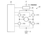
図2に示すように、反力発生モータ13の駆動回路29は、従来から存在するHブリッジ回路であり、反力発生モータ制御手段24に連絡したフェールセーフリレー30と、反力発生モータ制御手段24に連絡したモータ駆動用素子(スイッチイング素子)としての4つの第1モータ駆動用素子(Tr1)31A〜第4モータ駆動用素子(Tr4)31Dと、一側の端子13Aが第1モータ駆動用素子(Tr1)31A・第2モータ駆動用素子(Tr2)31Bに連絡するとともに他側の端子13Bが第3モータ駆動用素子(Tr3)31C・第4モータ駆動用素子(Tr4)31Dに連絡した反力発生モータ13とを備えている。この場合、フェールセーフリレー30は、モータ駆動電源Pに連絡している。第1モータ駆動用素子(Tr1)31Aと第3モータ駆動用素子(Tr3)31Cとは、それぞれ連絡するとともに、フェールセーフリレー30に連絡している。また、第2モータ駆動用素子(Tr2)31Bと第4モータ駆動用素子(Tr4)31Cとは、それぞれ連絡するとともに、アース(GND)Eに連絡している。
そして、反力発生モータ13は、4つの第1モータ駆動用素子(Tr1)31A〜第4モータ駆動用素子(Tr4)31Dをデューティ(Duty)制御することで、正逆転される。
更に、反力発生モータ13の駆動用電源は、フェールセーフリレー30にて供給・停止される。
更にまた、第2モータ駆動用素子(Tr2)31B・第4モータ駆動用素子(Tr4)31Dをオンとすることで、従来のように、電磁ブレーキがかかる状態とすることが可能である。
As shown in FIG. 2, the
The reaction
Further, the power for driving the reaction
Furthermore, by turning on the second motor driving element (Tr2) 31B and the fourth motor driving element (Tr4) 31D, the electromagnetic brake can be applied as in the prior art.
反力発生モータ制御手段24は、反力発生が停止する異常状態か否かを検出する異常検出手段24Bを備え、この異常検出手段24Bにより反力発生が停止する異常状態が検出された時には反力発生モータ13の端子13A、13B間を短絡させる。
また、反力発生モータ制御手段24は、異常検出手段24Bにより反力発生が停止する異常状態が検出されている時には、第1操作角検出手段10・第2操作角検出手段12により検出されるステアリングホイール操作角に基づいて反力発生モータ13の端子13A、13B間を断続的に短絡させる。
更に、反力発生モータ制御手段24は、異常検出手段24Bにより反力発生が停止する異常状態が検出される直前の反カトルク値を記憶する記憶手段24Cを備え、異常検出手段24Bにより反力発生が停止する異常状態発生時には、記憶手段24Cに記憶された反力トルク値になるように反力発生モータ13の端子13A、13B間を断続的に短絡させる。
更にまた、反力発生モータ13の駆動回路29は、従来から存在するHブリッジ回路である。反力発生モータ制御手段24は、異常検出手段24Bにより反力発生が停止する異常状態が検出されていない時には、Hブリッジ回路である駆動回路29の4つのモータ駆動用素子31A〜31Dを制御することによって反力発生モータ13の回転を制御し、一方、異常検出手段24Bにより反力発生が停止する異常状態が検出されている時には、第1〜第4モータ駆動用素子31A〜31Dをデューティ(Duty)制御して反力発生モータ13の端子13A、13B間を断続的に短絡させる。
The reaction force generation motor control means 24 includes an abnormality detection means 24B that detects whether or not the reaction force generation is in an abnormal state. When the abnormality detection means 24B detects an abnormal state in which the reaction force generation stops, the reaction force generation motor control means 24 The
The reaction force generation motor control means 24 is detected by the first operation angle detection means 10 and the second operation angle detection means 12 when the abnormality detection means 24B detects an abnormal state where reaction force generation stops. The
Further, the reaction force generation
Furthermore, the
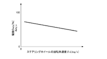
このため、反力発生モータ制御手段24は、図3に示すような駆動デューティマップ24Dを備え、ステアリングホイール7の回転角速度θv([deg/s])に応じた駆動デューティ値(duty_v)を求める。なお、図3においては、例えば、ステアリングホイールの回転角速度θvが大きくなる程、駆動デューティ値(duty_v)が減少する。
Therefore, the reaction force generation motor control means 24 includes a
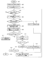
次に、この実施例に係るステアリングホイール7の反力制御について、図1のフローチャートに基づいて説明する。この制御は、反力発生モータ13を駆動することで、反力制御停止となる不具合の発生時にもステアリングホイール7の手応え感を提供するものである。
図1に示すように、制御装置23のプログラムがスタートすると(ステップA01)、現在の反力出力値(trq0)を取得して初期トルクとし(ステップA02)、F=1(出力未整合フラグ=1)とする(ステップA03)。
そして、フェール時モータ駆動条件が成立したか否かを判断する(ステップA04)。
このフェール時モータ駆動条件は、反力発生モータ制御手段24のCPU24Aが正常であることの条件と、反力発生モータ13が正常であることの条件と、全ての第1〜第4モータ駆動用素子31A〜31Dが正常であることの条件と、反力制御継続不可能条件が成立した場合の全ての条件が成立した場合に、成立する。
このステップA04がYESの場合には、第1モータ駆動用素子31A・第3モータ駆動用素子31Cをオフとする(ステップA05)。
そして、初期トルク(trq0)相当のデューティ(Duty)値を設定済みか否かを判断する(ステップA06)。
このステップA06がNOの場合には、最終出力反力トルク値duty_out=trq0に相当するデューティ値とする(ステップA07)。
このステップA06がYESの場合には、ステアリングホイール7の回転角速度θvを計算し(ステップA08)、そして、図3に示すように、駆動デューティマップからステアリングホイール7の回転角速度θv([deg/s])に応じた駆動デューティ値duty_vを求める(ステップA09)。
そして、F=1か否か、つまり、出力整合が必要か否かを判断する(ステップA10)。
このステップA10がYESの場合には、出力差分duty_diffを、duty_diff=duty_out−duty_vで計算する(ステップA11)。
次いで、duty_diff=0か否かを判断する(ステップA12)。
このステップA12がYESの場合には、F=0(整合完了)とする(ステップA13)。
このステップA13の処理後、又は、前記ステップA10がNOの場合には、duty_out=duty_vとする(ステップA14)。
前記ステップA12がNOの場合には、出力差分の20%を、duty_out=duty_out−duty_diff*0.2で補正する(ステップA15)。つまり、図3の駆動デューティマップから求めた駆動デューティ値duty_vに近づけるようにする。
このステップA15の処理後、前記ステップA14の処理後、又は、前記ステップA07の処理後は、第2モータ駆動用素子31B・第4モータ駆動用素子31Dを、最終出力反力トルク値となるように、duty_outで駆動し(ステップA16)、前記ステップA04に戻る。
一方、前記ステップA04がNOの場合には、全ての第1モータ駆動用素子31A〜第4モータ駆動用素子31Dをオフとし(ステップA17)、プログラムをエンドとする(ステップA18)。
Next, reaction force control of the steering wheel 7 according to this embodiment will be described based on the flowchart of FIG. In this control, the reaction
As shown in FIG. 1, when the program of the
Then, it is determined whether or not a failure motor drive condition is satisfied (step A04).
The failure motor drive conditions include the condition that the
If this step A04 is YES, the first
Then, it is determined whether or not a duty value corresponding to the initial torque (trq0) has been set (step A06).
When this step A06 is NO, it is set as the duty value corresponding to the final output reaction force torque value duty_out = trq0 (step A07).
If this step A06 is YES, the rotational angular velocity θv of the steering wheel 7 is calculated (step A08), and the rotational angular velocity θv ([deg / s] of the steering wheel 7 is calculated from the drive duty map as shown in FIG. ] Is determined (step A09).
Then, it is determined whether F = 1, that is, whether output matching is necessary (step A10).
When this step A10 is YES, the output difference duty_diff is calculated by duty_diff = duty_out−duty_v (step A11).
Next, it is determined whether or not duty_diff = 0 (step A12).
If this step A12 is YES, F = 0 (alignment completion) is set (step A13).
After step A13 or when step A10 is NO, duty_out = duty_v is set (step A14).
When step A12 is NO, 20% of the output difference is corrected by duty_out = duty_out-duty_diff * 0.2 (step A15). That is, the drive duty value duty_v obtained from the drive duty map of FIG.
After the process of step A15, after the process of step A14 or after the process of step A07, the second
On the other hand, when step A04 is NO, all the first
以上この発明の実施例について説明してきたが、上述の実施例の構成を請求項毎に当てはめて説明する。
先ず、請求項1に係る発明において、反力発生モータ制御手段24は、異常検出手段24Bにより反力発生が停止する異常状態が検出されている時には、第1操作角検出手段10・第2操作角検出手段12により検出されるステアリングホイール操作角に基づいて反力発生モータ13の端子13A、13B間を断続的に短絡させる。
これにより、反力発生が停止する異常発生時からシステム電源停止時まで、ステアリングホイール7の手応え感をステアリングホイール操作角に応じて最適に調整することができる。
請求項2に係る発明において、反力発生モータ制御手段24は、異常検出手段24Bにより反力発生が停止する異常状態が検出される直前の反カトルク値を記憶する記憶手段24Cを備え、異常検出手段24Bにより反力発生が停止する異常状態発生時には、記憶手段24Cに記憶された反力トルク値になるように反力発生モータ13の端子13A、13B間を断続的に短絡させる。
これにより、急操舵中に反力制御が継続できなくなった場合でも、ステアリングホイール7の手応え感の急変を防ぐことが可能となり、ステアリングホイール7の切り過ぎを防止して操舵することが可能となる。
請求項3に係る発明において、反力発生モータ13の駆動回路29は、Hブリッジ回路である。反力発生モータ制御手段24は、異常検出手段24Bにより反力発生が停止する異常状態が検出されていない時には、Hブリッジ回路である駆動回路29の4つのモータ駆動用素子31A〜31Dを制御することによって反力発生モータ13の回転を制御し、一方、異常検出手段24Bにより反力発生が停止する異常状態が検出されている時には、モータ駆動用素子31A〜31Dをデューティ(Duty)制御して反力発生モータ13の端子13A、13B間を断続的に短絡させる。
これにより、従来から使用しているモータ駆動回路29のままで、反力発生が停止する異常時に、運転者にステアリングホイール7の手応え感を与えることができる。
Although the embodiments of the present invention have been described above, the configuration of the above-described embodiments will be described for each claim.
First, in the invention according to
As a result, the responsiveness of the steering wheel 7 can be optimally adjusted according to the steering wheel operating angle from the occurrence of an abnormality that stops the reaction force generation to the stop of the system power supply.
In the invention according to
As a result, even when the reaction force control cannot be continued during sudden steering, it is possible to prevent a sudden change in the feeling of response of the steering wheel 7 and to steer while preventing the steering wheel 7 from being overcut. .
In the invention according to claim 3, the
As a result, it is possible to give the driver a sense of responsiveness to the steering wheel 7 at the time of an abnormality in which the reaction force generation stops with the
また、この実施例においては、従来の引用文献1と対比して、以下のような特有の作用効果がある。
先ず、機械的バックアップ装置を不要として、反力発生が停止する異常発生時からシステム電源停止時まで、ステアリングホイール操作角に応じた手応え感を運転者に与えるため、反力発生モータ13の端子13A、13B間を断続的に短絡するように駆動回路29の各モータ駆動用素子(スイッチング素子)をデューテイ制御できる。
また、正常時の反力トルク値を記憶しておき、異常発生時には、異常が発生する直前の反力トルク値になるように制御し、ステアリングホイール7の手応え感の急変を防ぐことができる。
更に、リレースイッチを不要とし、構成を簡単にするとともに、廉価にできる。
更にまた、従来の引用文献1と同様に、電力供給回路の駆動電流値等をモニタリングすることで、異常を検出可能とし、有効的である。
また、フェール時モータ駆動条件が成立したときに、第1モータ駆動用素子31A・第3モータ駆動用素子31Cをオフとするため、フェールセーフリレー30の状態にかかわらず、ステアリングホイール7の制御を実行可能とする。
更に、通常のフェールセーフリレー30とHブリッジを使った駆動回路29のみを用いて、ステアリングホイール7の急激なトルクダウンを補うことができ、従来のように、異常発生から機械的なバックアップ動作に移るまでの間のみ利用するのではなく、異常発生からシステム電源停止(システム停止)までの間で利用可能となる。
Further, in this embodiment, there are the following specific effects as compared with the conventional cited
First, since a mechanical backup device is not required, the terminal 13A of the reaction
Further, the reaction force torque value at the normal time is stored, and when an abnormality occurs, the reaction force torque value immediately before the occurrence of the abnormality is controlled to prevent a sudden change in the feeling of response of the steering wheel 7.
Further, the relay switch is not required, the configuration can be simplified and the cost can be reduced.
Furthermore, as in the case of the conventional cited
Further, since the first
Furthermore, it is possible to compensate for the sudden torque reduction of the steering wheel 7 using only the normal fail-
この発明に係るステアバイワイヤシステムを、各種車両に適用可能である。 The steer-by-wire system according to the present invention can be applied to various vehicles.
1 車両
2 ステアバイワイヤシステム
3 操作機構
4 操舵機構
5 ステアリングコラム
6 ステアリングシャフト
7 ステアリングホイール
10 第1操作角検出手段
11 トルクセンサ
12 第2操作角検出手段
13 反力発生モータ
14L 左前輪(操舵輪)
14R 右前輪(操舵輪)
21 第1操舵モータ
22 第2操舵モータ
23 制御装置
24 反力発生モータ制御手段
26 第1操舵用制御手段
27 第2操舵用制御手段
29 駆動回路(Hブリッジ回路)
30 フェールセーフリレー
31A〜31D モータ駆動用素子
DESCRIPTION OF
14R Right front wheel (steering wheel)
DESCRIPTION OF
30 Fail-
Claims (3)
Priority Applications (1)
| Application Number | Priority Date | Filing Date | Title |
|---|---|---|---|
| JP2011002828A JP2012144111A (en) | 2011-01-11 | 2011-01-11 | Steer-by-wire system |
Applications Claiming Priority (1)
| Application Number | Priority Date | Filing Date | Title |
|---|---|---|---|
| JP2011002828A JP2012144111A (en) | 2011-01-11 | 2011-01-11 | Steer-by-wire system |
Publications (1)
| Publication Number | Publication Date |
|---|---|
| JP2012144111A true JP2012144111A (en) | 2012-08-02 |
Family
ID=46788163
Family Applications (1)
| Application Number | Title | Priority Date | Filing Date |
|---|---|---|---|
| JP2011002828A Pending JP2012144111A (en) | 2011-01-11 | 2011-01-11 | Steer-by-wire system |
Country Status (1)
| Country | Link |
|---|---|
| JP (1) | JP2012144111A (en) |
Cited By (6)
| Publication number | Priority date | Publication date | Assignee | Title |
|---|---|---|---|---|
| WO2014188470A1 (en) * | 2013-05-21 | 2014-11-27 | トヨタ自動車株式会社 | Steering device |
| EP3351455A1 (en) | 2017-01-18 | 2018-07-25 | JTEKT Corporation | Steer-by-wire steering system |
| JP6435080B1 (en) * | 2018-06-29 | 2018-12-05 | 株式会社ショーワ | Steering device |
| CN112238896A (en) * | 2019-07-18 | 2021-01-19 | 上海燧方智能科技有限公司 | Vehicle steering method, system, steering method of running mechanism and running mechanism |
| CN114482834A (en) * | 2022-01-26 | 2022-05-13 | 张跃 | Curtain pull rope |
| JP2023535205A (en) * | 2020-07-28 | 2023-08-16 | ジェイテクト ユーロップ | A magnetic braking method for a steering column included in a vehicle steering system |
-
2011
- 2011-01-11 JP JP2011002828A patent/JP2012144111A/en active Pending
Cited By (8)
| Publication number | Priority date | Publication date | Assignee | Title |
|---|---|---|---|---|
| WO2014188470A1 (en) * | 2013-05-21 | 2014-11-27 | トヨタ自動車株式会社 | Steering device |
| EP3351455A1 (en) | 2017-01-18 | 2018-07-25 | JTEKT Corporation | Steer-by-wire steering system |
| US10850763B2 (en) | 2017-01-18 | 2020-12-01 | Jtekt Corporation | Steer-by-wire steering system |
| JP6435080B1 (en) * | 2018-06-29 | 2018-12-05 | 株式会社ショーワ | Steering device |
| WO2020003506A1 (en) * | 2018-06-29 | 2020-01-02 | 株式会社ショーワ | Steering device |
| CN112238896A (en) * | 2019-07-18 | 2021-01-19 | 上海燧方智能科技有限公司 | Vehicle steering method, system, steering method of running mechanism and running mechanism |
| JP2023535205A (en) * | 2020-07-28 | 2023-08-16 | ジェイテクト ユーロップ | A magnetic braking method for a steering column included in a vehicle steering system |
| CN114482834A (en) * | 2022-01-26 | 2022-05-13 | 张跃 | Curtain pull rope |
Similar Documents
| Publication | Publication Date | Title |
|---|---|---|
| JP5181548B2 (en) | Electric power steering device | |
| US6658333B2 (en) | Control apparatus of power steering device | |
| US20140005894A1 (en) | Electric power steering apparatus | |
| JP5136283B2 (en) | Electric power steering device | |
| US7268988B2 (en) | Apparatus and method for detecting rotation | |
| WO2011105154A1 (en) | Electric power steering device | |
| JP2005047433A (en) | Stabilizer control device | |
| JP2002535192A (en) | Torque generating device and driving method thereof | |
| WO2021125127A1 (en) | Electronic control device and power source system | |
| EP1752351B1 (en) | Electric brake and electric brake control apparatus | |
| JP2004330883A (en) | Variable transmission ratio steering system | |
| JP4719901B2 (en) | Rear wheel steering angle control device | |
| WO2018078870A1 (en) | Control apparatus and method for controlling control apparatus | |
| WO2006123839A1 (en) | Electric power steering system device controller | |
| JP2006062627A (en) | Steering reaction force control device | |
| JP4475049B2 (en) | Vehicle steering system | |
| JP2011251640A (en) | Vehicle steering device | |
| JP4810818B2 (en) | Electric power steering device | |
| WO2005081386A1 (en) | Relay adhesion preventing device and motor drive device | |
| JP4449840B2 (en) | Battery deterioration detection device | |
| JP4243146B2 (en) | Battery state determination device in electric steering device | |
| JP5050402B2 (en) | Vehicle steering control device | |
| JP3139872B2 (en) | Abnormality detection device for brushless motor | |
| JP4581535B2 (en) | Electric power steering device | |
| JP4062207B2 (en) | Vehicle steering system |