WO2016157603A1 - カプセル型内視鏡保持装置 - Google Patents
カプセル型内視鏡保持装置 Download PDFInfo
- Publication number
- WO2016157603A1 WO2016157603A1 PCT/JP2015/082153 JP2015082153W WO2016157603A1 WO 2016157603 A1 WO2016157603 A1 WO 2016157603A1 JP 2015082153 W JP2015082153 W JP 2015082153W WO 2016157603 A1 WO2016157603 A1 WO 2016157603A1
- Authority
- WO
- WIPO (PCT)
- Prior art keywords
- capsule endoscope
- holding
- surface portion
- holding apparatus
- modification
- Prior art date
- Legal status (The legal status is an assumption and is not a legal conclusion. Google has not performed a legal analysis and makes no representation as to the accuracy of the status listed.)
- Ceased
Links
- ZZIYOZFERMXGHB-UHFFFAOYSA-N CC(C)(C1)CC1N Chemical compound CC(C)(C1)CC1N ZZIYOZFERMXGHB-UHFFFAOYSA-N 0.000 description 1
- OWUBVBMWNZIFKA-UHFFFAOYSA-N CCC(CN)[IH]C Chemical compound CCC(CN)[IH]C OWUBVBMWNZIFKA-UHFFFAOYSA-N 0.000 description 1
Images














Classifications
-
- A—HUMAN NECESSITIES
- A61—MEDICAL OR VETERINARY SCIENCE; HYGIENE
- A61B—DIAGNOSIS; SURGERY; IDENTIFICATION
- A61B1/00—Instruments for performing medical examinations of the interior of cavities or tubes of the body by visual or photographical inspection, e.g. endoscopes; Illuminating arrangements therefor
Definitions
- the present invention relates to a capsule endoscope holding apparatus that holds a capsule endoscope.
- capsule medical devices equipped with an imaging function and a wireless function have appeared.
- This capsule endoscope is used for observation (examination) after being swallowed by the subject, and during the observation period until it is naturally discharged from the subject's living body, organs such as the stomach and small intestine
- the inside moves with the peristaltic motion, and images are sequentially captured using an imaging function.
- Some capsule endoscopes have a reed switch inside.
- a power source starter that generates a magnetic field is brought close to a capsule endoscope holding device in which the capsule endoscope is housed, and a magnetic field is applied to the reed switch, whereby the capsule endoscope
- the driving state of the endoscope is switched from the off state to the on state.
- the driving state of the capsule endoscope can be switched from the off state to the on state at an arbitrary timing, and the power consumption of the capsule endoscope can be controlled.
- the capsule endoscope holding device disclosed in Patent Document 1 since the capsule endoscope is disposed at the center of the internal space of the package, the capsule endoscope is used as the capsule endoscope holding device. It is not always easy to turn on the power in the accommodated state. Before introducing the subject, it is preferable to handle the capsule endoscope as much as possible without touching the outside air or the operator, and the power can be easily turned on with the capsule endoscope housed in the capsule endoscope holding device. It was hoped that.
- the present invention has been made in view of the above, and an object of the present invention is to provide a capsule endoscope holding device that can easily turn on a power supply in a state in which the capsule endoscope is accommodated. To do.
- a capsule endoscope holding apparatus includes a capsule endoscope that is introduced into a subject and captures an image in the subject.
- the holding position is any of the first and second positions. It is characterized by changing.
- the capsule endoscope holding apparatus according to the present invention is characterized in that, in the above invention, a part of the capsule endoscope holding apparatus is deformed according to an external force.
- the capsule endoscope holding device is the above invention, wherein the capsule endoscope holding device has a bottomed cylindrical shape for holding the capsule endoscope, and extends at an inclination from the opening end of the holding portion, A weight-like inclined portion that can be deformed into two different inclined modes in which the holding position of the capsule endoscope is the first or second position, and a side that is different from a side that is continuous with the holding portion of the inclined portion. And a cylindrical wall portion extending from the end portion.
- the position of the capsule endoscope changes from the first position to the second position in response to the external force.
- the unit is preliminarily provided with a restoring force for restoring the holding position to the second position.
- the capsule endoscope holding apparatus according to the present invention is characterized in that, in the above invention, the rigidity of the inclined portion is higher than the rigidity of the wall portion.
- the capsule endoscope holding apparatus according to the present invention is characterized in that, in the above invention, the thickness of the inclined portion is larger than the thickness of the wall portion.
- the inclined portion has a wave shape.
- the inclined portion has a plurality of convex portions extending from one end to the other end on the side connected to the holding portion.
- the holding unit that holds the capsule endoscope and the holding unit are relatively moved by the change in the first and second positions. And a telescopic stretchable portion extending in a bellows shape along the moving direction.
- the capsule endoscope holding apparatus is the above-described invention, wherein the capsule endoscope holding device includes a top surface portion having a holding portion for holding the capsule endoscope, a bottom surface portion provided to face the top surface portion, The upper surface portion and the bottom surface portion are connected at both ends, respectively, and at least a side surface portion having rigidity lower than that of the upper surface portion is provided.
- the upper surface portion, the bottom surface portion provided to face the upper surface portion, the upper surface portion and the bottom surface portion are respectively connected at both ends, A side surface portion having rigidity lower than that of at least the upper surface portion; a holding portion for holding the capsule endoscope; and a rigidity higher than that of the upper surface portion, from the end of the holding portion to the bottom surface portion side. It is characterized by comprising a weight-like inclined portion that extends in a slanted manner and can be transformed into two different inclined modes, and is connected to the inner peripheral surface of the side surface portion.
- the capsule endoscope holding apparatus is characterized in that, in the above invention, the upper surface portion and the inclined portion are thicker than the side surface.
- the upper surface portion and the inclined portion have a wave shape.
- the capsule endoscope holding apparatus is characterized in that, in the above invention, the upper surface portion and the inclined portion have a plurality of convex portions extending from one end to the other end.
- the capsule endoscope holding apparatus according to the present invention is characterized in that, in the above invention, a part of the capsule endoscope holding apparatus is deformed in response to heat.
- the capsule endoscope holding apparatus is the above-described invention, wherein the capsule endoscope holding device includes a top surface portion having a holding portion for holding the capsule endoscope, a bottom surface portion provided to face the top surface portion, And a side surface portion that connects the upper surface portion and the bottom surface portion at both ends, respectively, and is formed of a material that expands and contracts by heat.
- the holding position changes to one of the first and second positions due to the drop of the capsule endoscope.
- the capsule endoscope holding apparatus according to the present invention is characterized in that, in the above invention, the capsule endoscope is dropped in response to an external force.
- the upper surface portion, the bottom surface portion provided to face the upper surface portion, the upper surface portion and the bottom surface portion are respectively connected at both ends, A side surface portion having rigidity lower than that of at least the upper surface portion; a first holding portion for holding the capsule endoscope in the first position; and one end connected to the side surface portion, and the other end A support unit that supports the first holding unit; and a second holding unit that is provided vertically below the first holding unit and holds the capsule endoscope at the second position.
- the upper surface portion, the bottom surface portion provided to face the upper surface portion, the upper surface portion and the bottom surface portion are respectively connected at both ends,
- a main body portion including at least a side surface portion having rigidity lower than that of the upper surface portion; and a holding portion that is detachably provided on an inner peripheral surface of the side surface portion and holds the capsule endoscope. It is characterized by having.
- the capsule endoscope holding apparatus is characterized in that, in the above invention, the holding part is held on the side part by bonding or fitting with a bonding material.
- the capsule endoscope holding apparatus according to the present invention is characterized in that, in the above invention, the thickness of the upper surface portion is larger than the thickness of the side surface portion.
- the capsule endoscope holding apparatus is characterized in that, in the above invention, the upper surface portion has a wave shape.
- the capsule endoscope holding apparatus is characterized in that, in the above invention, the upper surface portion has a plurality of convex portions extending from one end to the other end.
- the capsule endoscope holding apparatus according to the present invention is characterized in that, in the above invention, the capsule endoscope is dropped in response to heat.
- the capsule endoscope holding apparatus is the above-described invention, wherein the upper surface portion, the bottom surface portion provided to face the upper surface portion, and the side surfaces connecting the upper surface portion and the bottom surface portion at both ends are provided. And a holding part that holds the capsule endoscope and is held on the inner peripheral surface of the side part by a bonding material that can be melted by heat. .
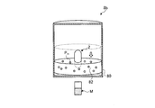
- the holding position changes to one of the first and second positions by the movement of the capsule endoscope.
- the capsule endoscope holding apparatus is characterized in that, in the above invention, the capsule endoscope moves in accordance with a magnetic force.
- the capsule endoscope holding apparatus is the above-described invention, wherein the upper surface portion, the bottom surface portion provided to face the upper surface portion, and the side surfaces connecting the upper surface portion and the bottom surface portion at both ends are provided. And a holding portion that is held on the inner peripheral surface of the side surface portion, includes a magnetic material, and holds the capsule endoscope.
- the first and second positions are prevented from changing, and the first and second positions are prevented from changing at a desired timing. And a preventive member that can be released.
- the power can be easily turned on in a state where the capsule endoscope is accommodated in the capsule endoscope holding device.
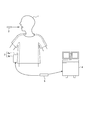
- FIG. 1 is a system conceptual diagram showing a concept of a capsule endoscope system according to Embodiment 1 of the present invention.
- FIG. 2 is a schematic cross-sectional view showing a configuration example of the capsule endoscope shown in FIG.
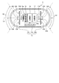
- FIG. 3 is a perspective view showing a configuration of the accommodation package according to the first exemplary embodiment of the present invention.
- FIG. 4 is a partial cross-sectional view taken along line AA shown in FIG. 3, and is a view in which the accommodation package is cut along a plane perpendicular to the longitudinal direction of the outer case.
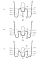
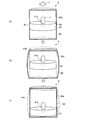
- FIG. 5 is a diagram illustrating a change in the holding position of the capsule endoscope housed in the housing package according to the first embodiment of the present invention.
- FIG. 1 is a system conceptual diagram showing a concept of a capsule endoscope system according to Embodiment 1 of the present invention.
- FIG. 2 is a schematic cross-sectional view showing a configuration example of the capsule endoscope shown in FIG.
- FIG. 3
- FIG. 6 is a diagram illustrating a change in the holding position of the capsule endoscope housed in the housing package according to the first modification of the first embodiment of the present invention.
- FIG. 7 is a diagram illustrating a change in the holding position of the capsule endoscope housed in the housing package according to the second modification of the first embodiment of the present invention.
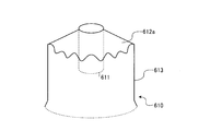
- FIG. 8 is a perspective view schematically showing the configuration of the recess according to the third modification of the first embodiment of the present invention.
- FIG. 9 is a perspective view schematically showing the configuration of the recess according to the fourth modification of the first embodiment of the present invention.
- FIG. 10 is a partial cross-sectional view showing the configuration of the accommodation package according to the second embodiment of the present invention.
- FIG. 11 is a fragmentary sectional view which shows the structure of the accommodation package concerning Embodiment 2 of this invention.
- FIG. 12 is a partial cross-sectional view schematically showing a configuration of a deformation preventing member that prevents deformation of the accommodation package according to the first modification of the second embodiment of the present invention.
- FIG. 13 is a fragmentary sectional view which shows typically the structure of the deformation
- FIG. 14 is a fragmentary sectional view which shows the structure of the accommodation package concerning Embodiment 3 of this invention.
- FIG. 15 is a fragmentary sectional view which shows the structure of the accommodation package concerning Embodiment 3 of this invention.
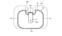
- FIG. 16 is a fragmentary sectional view which shows the structure of the accommodation package concerning the modification 1 of Embodiment 3 of this invention.
- FIG. 17 is a fragmentary sectional view which shows the structure of the accommodation package concerning the modification 1 of Embodiment 3 of this invention.
- FIG. 18 is a fragmentary sectional view which shows the structure of the accommodation package concerning the modification 2 of Embodiment 3 of this invention.
- FIG. 19 is a diagram illustrating a change in the holding position of the capsule endoscope housed in the housing package according to the second modification of the third embodiment of the present invention.
- FIG. 20 is a partial cross-sectional view showing the configuration of the accommodation package according to the third modification of the third embodiment of the present invention.
- FIG. 21 is a diagram illustrating a change in the holding position of the capsule endoscope housed in the housing package according to the third modification of the third embodiment of the present invention.
- FIG. 22 is a partial cross-sectional view schematically showing a configuration of a deformation preventing member that prevents deformation of the accommodation package according to the fourth modification of the third embodiment of the present invention.
- FIG. 23 is a top view showing the configuration of the deformation preventing member as seen from the direction of arrow B shown in FIG.
- FIG. 24 is a partial cross-sectional view schematically showing a configuration of a deformation preventing member that prevents deformation of the accommodation package according to the fourth modification of the third embodiment of the present invention.
- FIG. 22 is a partial cross-sectional view schematically showing a configuration of a deformation preventing member that prevents deformation of the accommodation package according to the fourth modification of the third embodiment of the present invention.
- FIG. 25 is a partial cross-sectional view schematically showing a configuration of a deformation preventing member for preventing deformation of the accommodation package according to the fifth modification of the third embodiment of the present invention.
- FIG. 26 is a partial cross-sectional view schematically showing a configuration of a deformation preventing member that prevents deformation of the accommodation package according to the fifth modification of the third embodiment of the present invention.
- FIG. 27 is a partial cross-sectional view showing the configuration of the accommodation package according to the fourth embodiment of the present invention.
- FIG. 28 is a diagram illustrating a change in the holding position of the capsule endoscope housed in the housing package according to the fourth embodiment of the present invention.
- FIG. 29 is a partial cross-sectional view illustrating a configuration of a storage package according to Modification 1 of Embodiment 4 of the present invention.
- FIG. 30 is a diagram illustrating a change in the holding position of the capsule endoscope housed in the housing package according to the first modification of the fourth embodiment of the present invention.
- FIG. 31 is a partial cross-sectional view showing the configuration of the accommodation package according to the second modification of the fourth embodiment of the present invention.
- FIG. 32 is a diagram illustrating a change in the holding position of the capsule endoscope housed in the housing package according to the second modification of the fourth embodiment of the present invention.
- FIG. 1 is a system conceptual diagram showing the concept of a capsule endoscope system according to the present invention.
- the capsule endoscope system is a swallowable capsule endoscope that is introduced into a subject 1 and functions as a capsule medical device that captures an image inside the subject 1 and wirelessly transmits the image to the outside.
- An endoscope 2 and a receiving device 3 that is disposed outside the subject 1 and is an extracorporeal device that wirelessly communicates various types of information with the capsule endoscope 2 are provided.
- the wireless in-vivo information acquiring system includes a display device 4 that displays an image based on data received by the receiving device 3, and a portable recording medium that inputs and outputs data between the receiving device 3 and the display device 4. And 5.
- the receiving device 3 functions as a wireless receiving unit that receives image data in the subject wirelessly transmitted from the capsule endoscope 2.
- the receiving device 3 includes a receiving jacket 3a that is worn on the subject 1 and includes a plurality of receiving antennas (not shown), and an external device 3b that performs signal processing of received radio signals.
- the display device 4 is for displaying an in-subject image captured by the capsule endoscope 2, and is a workstation or the like that displays an image based on data obtained by the portable recording medium 5. It has a configuration. Specifically, the display device 4 may be configured to directly display an image using a liquid crystal display or the like, or may be configured to output an image to another medium such as a printer.
- the portable recording medium 5 can be connected to the external device 3b and the display device 4, and is attached to both, and has a structure capable of outputting or recording information when connected.
- the portable recording medium 5 stores data that is inserted into the external device 3b and transmitted from the capsule endoscope 2 while the capsule endoscope 2 is moving in the subject 1. Record. Next, after the capsule endoscope 2 is ejected from the subject 1, that is, after the imaging in the subject 1 is completed, the capsule endoscope 2 is taken out from the external device 3b and inserted into the display device 4, and this display device 4, the data recorded on the portable recording medium 5 is read out.
- the portable recording medium 5 is configured by a compact flash (registered trademark) memory or the like, and data input / output between the external device 3 b and the display device 4 can be indirectly performed via the portable recording medium 5.
- the subject 1 can freely operate during imaging of the in-subject image.
- FIG. 2 is a schematic cross-sectional view showing a configuration example of the capsule endoscope 2 shown in FIG.
- the capsule endoscope 2 captures images of subjects in different imaging directions from a capsule-type casing 12 that is an exterior formed in a size that can be easily introduced into an organ of a subject. Imaging sections 11A and 11B.
- the capsule endoscope 2 controls the wireless communication unit 16 that wirelessly transmits each image captured by the imaging units 11A and 11B to the outside through the antenna 16a, and each component of the capsule endoscope 2.
- Unit 17 and a power supply unit 18 that supplies power to each component of the capsule endoscope 2.
- the capsule-type housing 12 is an outer case formed in a size that can be introduced into an organ of a subject, and is realized by closing both side opening ends of the cylindrical housing 12a with dome-shaped housings 12b and 12c.
- the dome-shaped casings 12b and 12c are dome-shaped optical members that are transparent to light of a predetermined wavelength band such as visible light.
- the cylindrical housing 12a is a colored housing that is substantially opaque to visible light.
- the capsule housing 12 formed by the cylindrical housing 12a and the dome-shaped housings 12b and 12c includes an imaging unit 11A, 11B, a wireless communication unit 16, a control unit 17, and a power supply unit 18. In a liquid-tight manner.
- the imaging units 11A and 11B capture images in different imaging directions.
- the imaging unit 11A includes an illumination unit 13A such as an LED, an optical system 14A such as a condenser lens, and an imaging element 15A such as a CMOS image sensor or a CCD.
- the illuminator 13A emits illumination light such as white light to the imaging field S1 of the imaging device 15A, and the subject in the imaging field S1 (for example, the inner wall of the organ on the imaging field S1 side inside the subject) through the dome-shaped housing 12b. ).
- the optical system 14A condenses the reflected light from the imaging field S1 on the imaging surface of the imaging element 15A, and forms the subject image of the imaging field S1 on the imaging surface of the imaging element 15A.
- the imaging element 15A receives the reflected light from the imaging field S1 through the imaging surface, performs photoelectric conversion processing on the received optical signal, and subjects the subject image in the imaging field S1 (view angle ⁇ ), that is, the subject image.
- An in-vivo image (in-subject image) of the sample is taken.
- the imaging unit 11B includes an illumination unit 13B such as an LED, an optical system 14B such as a condenser lens, and an imaging element 15B such as a CMOS image sensor or a CCD.
- the illumination unit 13B emits illumination light such as white light to the imaging field S2 of the imaging device 15B, and the subject in the imaging field S2 (for example, the inner wall of the organ on the imaging field S2 side inside the subject) through the dome-shaped housing 12c. ).
- the optical system 14B condenses the reflected light from the imaging field of view S2 on the imaging surface of the imaging element 15B, and forms an object image of the imaging field of view S2 on the imaging surface of the imaging element 15B.
- the imaging element 15B receives the reflected light from the imaging field of view S2 through the imaging surface, performs photoelectric conversion processing on the received optical signal, and subjects the subject image of the imaging field of view S2 (view angle ⁇ ), that is, the subject image. An in-specimen image is taken.
- the optical axes of the imaging units 11A and 11B are It is substantially parallel or substantially coincident with the long axis La, which is the central axis in the longitudinal direction of the capsule housing 12.
- the directions of the imaging fields of view S1 and S2 of the imaging units 11A and 11B, that is, the imaging directions of the imaging units 11A and 11B are opposite to each other.
- the control unit 17 controls each operation of the imaging units 11A and 11B and the wireless communication unit 16 that are components of the capsule endoscope 2, and controls input / output of signals between the components. Specifically, the control unit 17 causes the image sensor 15A to capture an image of the subject in the imaging field S1 illuminated by the illumination unit 13A, and the image of the subject in the imaging field S2 illuminated by the illumination unit 13B. Let's take an image.
- the control unit 17 has a signal processing function for generating an image signal.
- the control unit 17 acquires the in-vivo image data of the imaging field of view S1 from the imaging element 15A, and performs predetermined signal processing on the in-vivo image data each time to obtain an image signal including the in-vivo image data of the imaging field of view S1.
- control unit 17 acquires the in-vivo image data of the imaging field of view S2 from the imaging device 15B, and performs predetermined signal processing on the in-vivo image data each time to obtain the in-vivo image data of the imaging field of view S2. Is generated.
- the control unit 17 controls the wireless communication unit 16 so as to sequentially wirelessly transmit the image signals to the outside along the time series.
- the power supply unit 18 supplies power to each unit such as an illumination unit and an imaging unit.
- the power supply unit 18 has a reed switch 18a, and activation / stop of the power supply is controlled according to the switch operation of the reed switch 18a.
- the reed switch 18a performs a switching operation in response to a magnetic field applied from the outside. Specifically, the power supply unit 18 is turned on by bringing a starter that generates a magnetic field close to the lead axis of the reed switch 18a from a predetermined direction.
- the starter for the capsule endoscope 2 does not approach the lead axial direction of the reed switch 18a in the capsule endoscope 2 from a predetermined direction, the power supply of the capsule endoscope 2 is in the on state. It will not be.
- FIG. 3 is a perspective view showing the configuration of the accommodation package according to the first embodiment for accommodating the capsule endoscope shown in FIG.
- FIG. 4 is a partial cross-sectional view taken along line AA shown in FIG. 3, and is a view in which the accommodation package is cut along a plane perpendicular to the longitudinal direction of the outer case.
- the accommodation package 6 As shown in FIGS. 3 and 4, the accommodation package 6 according to the first embodiment is provided on the accommodation case 61 that holds the capsule endoscope 2 and the upper surface of the accommodation case 61. And a sterilization sheet 62 that closes the container.
- the housing case 61 is formed by, for example, forming processing such as vacuum forming using polypropylene or the like.
- the sterilization sheet 62 permeates air and blocks the permeation of bacteria.
- the storage case 61 includes a bottomed cylindrical portion 61a, a tongue-shaped handle portion 61b provided on a part of the upper edge of the cylindrical portion 61a, an upper edge of the cylindrical portion 61a, and an outer periphery of the handle portion 61b.
- the edge portion 61c provided on the outer periphery of the cylindrical portion 61a is provided on the peripheral surface of the cylindrical portion 61a and protrudes from the inside of the cylindrical portion 61a to the outside, and has a substantially semi-columnar shape formed along the longitudinal direction of the cylindrical portion 61a.
- a plurality of protrusions 61d is attached to the upper surface of the edge portion 61c.
- the concave portion 610 includes a bottomed cylindrical holding portion 611 that holds the capsule endoscope 2, a weight-like inclined portion 612 that extends from the upper end of the holding portion 611 toward the bottom side of the cylindrical portion 61 a, and an inclined portion And a cylindrical wall portion 613 extending from the end on the side different from the side connected to the holding portion 611 to the bottom side of the cylindrical portion 61a with a uniform diameter.
- the holding position of the capsule endoscope 2 changes to either the first position or the second position, which are different from each other, according to the external force.
- the diameter of the holding portion 611 formed by the inner peripheral surface is substantially the same as the diameter in the direction perpendicular to the long axis La of the capsule endoscope 2 (the diameter formed by the outer periphery of the cylindrical housing 12a).
- the inclined portion 612 forms an inclined surface extending at a predetermined angle with respect to the side surface of the holding portion 611.
- the outer surface of the inclined portion 612 and the side surface of the holding portion 611 form a predetermined angle ⁇ (0 ° ⁇ ⁇ 90 °).
- the wall portion 613 rises and extends to the upper end side of the cylindrical portion 61 a and forms the inner wall of the recess 610.
- the wall portion 613 which is a deformable portion, has a lower rigidity than that of the inclined portion 612, which is a highly rigid portion, and can be elastically deformed. For this reason, when a force is applied to the concave portion 610 from the outside, the wall portion 613 is elastically deformed preferentially over the inclined portion 612.
- the cylindrical portion 61a is integrally formed using the same material (for example, polypropylene), and the difference in rigidity between the inclined portion 612 and the wall portion 613 changes the thickness (thickness). It is adjusted by.
- the capsule endoscope 2 is held by the holding unit 611 so that the reed switch 18 a is positioned at the center of the housing package 6. Since the reed switch 18a of the capsule endoscope 2 is held at a position away from the external magnetic field by the housing package 6, it is possible to prevent the power supply from being turned on unintentionally.
- FIG. 5 is a diagram illustrating a change in the holding position of the capsule endoscope housed in the housing package according to the first embodiment.
- FIG. 5A shows a state in which the capsule endoscope 2 is held at the central portion (first position) of the housing package 6.
- FIG. 5B shows a state in the middle of changing the holding position of the capsule endoscope 2.
- FIG. 5C shows a state in which the capsule endoscope 2 is held on the bottom side (second position) of the housing package 6.
- the user or the like moves the holding portion 611 downward (to the bottom side of the cylindrical portion 61a).
- the inclined portion 612 moves with the movement of the holding portion 611.
- the inclined portion 612 moves in a direction in which the angle formed by the outer surface of the inclined portion 612 and the side surface of the holding portion 611 increases.
- the holding portion 611 is further moved downward, the upper end of the holding portion 611 becomes lower than the upper end of the wall portion 613, and the wall portion 613 also returns to its original shape from the elastically deformed state ((c in FIG. 5). )reference).
- the inclination of the inclined part 612 with respect to the holding part 611 is reversed.
- the capsule endoscope 2 is changed to a state of being held on the bottom side (second position) of the cylindrical portion 61a.
- the volume in the accommodation package 6 changes by the change of the holding position mentioned above.
- the position of the reed switch 18a is moved with the movement of the capsule endoscope 2. Also moves to the bottom side of the housing package 6.
- the reed switch 18a performs a switching operation by bringing the starter close from the lower side (to the bottom side of the housing package 6), and the power supply unit 18 is turned on. Thereby, power is supplied from the power supply unit 18 to each unit such as the illumination unit and the imaging unit.
- the capsule endoscope 2 when the capsule endoscope 2 is positioned at the central portion (first position) of the housing package 6, the starter is approached from below (to the bottom side of the housing package 6) in FIG.
- the reed switch 18a since the reed switch 18a does not exist in the magnetic field action range of the starter or the acting magnetic force is weak, the switch operation is not performed and the power supply unit 18 is not turned on.
- the reed switch 18a in the first position, the reed switch 18a is far from any direction on the outer periphery of the accommodation package 6, and it is difficult to turn on even if an unknown magnetic field approaches from any direction during transportation.
- the inclined portion 612 moves along with the movement of the holding portion 611, and according to the movement of the inclined portion 612. Since the wall portion 613 is elastically deformed and the inclination of the inclined portion 612 is reversed so that the position of the holding portion 611 is changed, the power can be easily turned on while the capsule endoscope 2 is accommodated. It can be.
- the reed switch that is not intended to be damaged due to the external force of the capsule endoscope 2 by being conveyed by the accommodation package 6 held in the first position or unintended.
- the switch operation of the reed switch 18a is performed while being held on the bottom side (second position) of the cylindrical portion 61a, and the power supply is turned on with a smaller magnetic field. Can do.
- the position of the holding unit 611 is changed by applying a force F to the holding unit 611.
- the capsule endoscope 2 is held at the first position. Since the accommodation package 6 in the state is not inadvertently changed to the second position during conveyance or the like, it is changed to the second position at any timing of the user, so that the capsule endoscope 2 Is held at the second position at an unintended timing, and the power supply unit 18 can be reliably prevented from being turned on.
- the difference in rigidity between the inclined portion 612 and the wall portion 613 has been described as being adjusted by changing the thickness of each portion, but materials using different rigidity and yield stress are used. Or a combination thereof.
- the material include resins such as polypropylene, polystyrene, and polyethylene terephthalate.
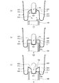
- FIG. 6 is a diagram illustrating a change in the holding position of the capsule endoscope housed in the housing package according to the first modification of the first embodiment.
- FIG. 6 is a diagram showing a state when the accommodation package 6 is molded, and shows a state where the holding portion 611 is located on the bottom side (second position) of the accommodation package 6.
- symbol is attached
- a restoring force for taking the state of the second position is applied to the inclined portion 612.
- the cylindrical portion 61a according to the first modification is molded such that the holding portion 621 is positioned on the bottom side (second position) of the storage package 6 when the storage package 6 is formed. After that, the holding unit 611 is moved to the first position, and the capsule endoscope 2 is held by the holding unit 611, whereby the accommodation package in which the capsule endoscope 2 is accommodated as shown in FIG. 6 can be obtained.
- the inclined portion 612 is formed so that the holding portion 611 is positioned on the bottom side (second position) of the housing package 6. In the state of being positioned, a restoring force is applied to the inclined portion 612 to take the state of the second position. For this reason, it is possible to change from the first position to the second position with a smaller force than in the first embodiment.
- FIG. 7 is a diagram illustrating a change in the holding position of the capsule endoscope housed in the housing package according to the second modification of the first embodiment.
- FIG. 7A shows a state in which the capsule endoscope 2 is held at the central portion (first position) of the housing package 6.
- FIG. 7B shows a state in the middle of changing the holding position of the capsule endoscope 2.
- FIG. 7C shows a state in which the capsule endoscope 2 is held on the bottom side (second position) of the housing package 6.
- symbol is attached
- the wall portion 613 has been described as extending with a uniform diameter. However, in the second modification, the wall portion has a weight shape with a diameter reduced from the bottom side to the upper end of the cylindrical portion. Eggplant.
- the cylindrical portion 61a according to the second modification has a recess 620 instead of the recess 610 described above.
- the concave portion 620 includes a bottomed cylindrical holding portion 621 that holds the capsule endoscope 2, a weight-like inclined portion 622 that extends from the upper end of the holding portion 621 to the bottom side of the cylindrical portion 61a, and an inclined portion. And a wall portion 623 having a hollow spindle shape whose diameter is reduced from the end portion on the side different from the side connected to the holding portion 621 to the upper end from the bottom side of the cylindrical portion 61a. Note that the inclined portion 622 will be described as having a restoring force as in the first modification.
- the holding part 621 has a diameter formed by the inner peripheral surface thereof is substantially the same as the diameter in the direction orthogonal to the long axis La of the capsule endoscope 2, similarly to the holding part 611 described above.
- the inclined portion 622 forms an inclined surface extending at a predetermined angle with respect to the side surface of the holding portion 621.
- the outer surface of the inclined portion 622 and the side surface of the holding portion 621 form a predetermined angle ⁇ 1 (0 ° ⁇ 1 ⁇ 90 °).
- the wall portion 623 rises and extends to the upper end side of the cylindrical portion 61 a and forms the inner wall of the recess 620.
- the wall portion 623 has a hollow weight shape with a diameter reduced from the bottom side to the upper end of the cylindrical portion 61a, and the outer surface of the wall portion 623 and the side surface of the holding portion 621 have a predetermined angle ⁇ 2 (0 ° ⁇ 0 ⁇ ⁇ 2 ⁇ 1 ⁇ 90 °).
- the cylindrical position changing member 100 is inserted into the recess 620.
- the diameter of the outer periphery of the position changing member 100 is larger than the minimum diameter of the inner periphery of the wall 623 and smaller than the maximum diameter. Further, the inner diameter of the position changing member 100 is larger than the outer diameter of the holding portion 621.
- the distal end on the insertion side comes into contact with the wall portion 623, and the wall portion 623 is expanded in diameter (see FIG. 7B).
- the inclined portion 622 also moves with the movement of the wall portion 623.
- the inclined portion 622 is moved to the second position side of the holding portion 621 by the expansion of the wall portion 623 and the restoring force added in advance.
- the holding portion 621 moves to the bottom side of the cylindrical portion 61a, and the capsule endoscope 2 is held at the second position ((c) in FIG. 7). Thereafter, the position changing member 100 is extracted from the recess 620.
- the position of the holding portion 621 can be changed by applying a force to the wall portion 623 using the position changing member 100.
- the power supply unit 18 can be turned on only by inserting the position change member 100, and the position change member 100 is used as a starter. Can be used.
- FIG. 8 is a perspective view schematically showing the configuration of the recess according to the third modification of the first embodiment.
- the rigidity between the inclined portion 612 and the wall portion 613 is adjusted by changing the wall thickness.
- the shape of the inclined portion is changed and the wall portion 613 is changed. Adjust the stiffness.
- the concave portion 610 according to the third modification has an inclined portion 612a instead of the inclined portion 612.
- the inclined portion 612a has a weight shape that is connected to the tip of the holding portion 611 and the tip of the wall portion 613 at both ends. Further, the inclined portion 612a has a wave shape along the circumferential direction. Thereby, rigidity can be made high compared with the case where planar shape is made.
- the “circumferential direction” is, for example, the circumferential direction of a circle formed by the opening of the holding portion 611.
- the inclined portion 612a since the inclined portion 612a has a wave shape along the circumferential direction of the side surface, even when the same material and the same thickness are used.
- the rigidity of the inclined portion 612a and the wall portion 613 can be adjusted.
- FIG. 9 is a perspective view schematically showing the configuration of the recess according to the fourth modification of the first embodiment.
- the rigidity between the inclined portion 612 and the wall portion 613 is adjusted by changing the wall thickness.
- the shape of the inclined portion is changed and the wall portion 613 is changed. Adjust the stiffness.
- the concave portion 610 according to the fourth modification has an inclined portion 612b instead of the inclined portion 612.
- the inclined portion 612b has a weight shape that connects to the tip of the holding portion 611 and the tip of the wall portion 613 at both ends.
- the inclined portion 612b includes a plurality of rib-shaped convex portions 612c extending in a prismatic shape along the extending direction.
- the plurality of convex portions 612c are radial in the top view of the inclined portion 612b.
- the plurality of convex portions 612c may be formed by deforming a part of the inclined portion 612b, or may be provided separately. Thereby, rigidity can be made high compared with the case where planar shape is made.
- the “extension direction” is a direction extending from an end (one end) on the side connected to the holding portion 611 toward an end (the other end) on the side connected to the wall 613, for example, a weight-like body Corresponds to the direction of the bus.
- the inclined portion 612b since the inclined portion 612b has the plurality of rib-shaped convex portions 612c extending in a prismatic shape, even if the same material is used, the inclined portion 612b and the wall The rigidity with the portion 613 can be adjusted.
- the convex part 612c should just protrude from the surface of an inclination part, such as what extends in a semicircular cross section other than prismatic shape.
- FIG. 10 is a partial cross-sectional view showing the configuration of the accommodation package according to the second embodiment and corresponds to the partial cross-sectional view along the line AA shown in FIG.
- symbol is attached
- the position of the holding portion 611 is changed by the inclined portion 612 and the wall portion 613 provided in the concave portion 610.
- the side surface portion of the cylindrical portion 63a is changed. Part of the shape is stretchable.
- the accommodation package 6 a according to the second embodiment is provided on the accommodation case 63 that holds the capsule endoscope 2 and the upper surface of the accommodation case 63, and closes the opening of the accommodation case 63. And a sterilization sheet 62.
- the housing case 63 includes a bottomed cylindrical portion 63a, a tongue-shaped handle portion 63b provided at a part of the upper edge of the cylindrical portion 63a, an upper edge of the cylindrical portion 63a, and an outer periphery of the handle portion 63b. And a plurality of substantially semi-columnar protrusions 63d formed in the longitudinal direction of the cylindrical portion 63a provided on the peripheral surface of the cylindrical portion 63a and projecting outward from the inside of the cylindrical portion 63a. And comprising.
- a sterilization sheet 62 is attached to the upper surface of the edge 63c.
- a concave part 630 having a holding part 630a for holding the capsule endoscope 2 is provided at the bottom of the cylindrical part 63a.
- the holding portion 630a has a bottomed cylindrical shape for holding the capsule endoscope 2, and the diameter formed by the inner peripheral surface is orthogonal to the long axis La of the capsule endoscope 2 as with the holding portion 611 described above. It is almost the same as the diameter in the direction.
- an expandable portion 631 that extends in a bellows shape in the vertical direction of the cylindrical portion 63a and can be expanded and contracted in the vertical direction.
- FIG. 11 is a partial cross-sectional view showing the configuration of the accommodation package according to the second embodiment, corresponding to the partial cross-sectional view along the line AA shown in FIG.
- the accommodation package 6a shown in FIG. 10 when a force is applied in a direction in which the bottom of the cylindrical portion 63a approaches the upper end (edge portion 63c), the telescopic portion 631 is compressed and the capsule endoscope 2 approaches the sterilization sheet 62.
- the position (see FIG. 10) of the capsule endoscope 2 (holding section 630a) in a state where the expansion / contraction section 631 is not compressed without applying force is set as the first position, and the expansion / contraction section 631 is used.
- the position (see FIG. 11) of the capsule endoscope 2 (holding portion 630a) in a state where is compressed is the second position.
- the capsule endoscope 2 is held at the center of the accommodation package 6a by the holding portion 630a in the holding state shown in FIG. Since the capsule endoscope 2 is held at a position away from the external magnetic field by the housing package 6a, it is possible to prevent the power supply from being turned on unintentionally.
- the capsule endoscope 2 is located at the sterilization sheet 62 side of the housing package 6a in the second position, for example, by approaching the starter from above in FIG. 11, that is, from the sterilization sheet side,
- the reed switch 18a performs a switching operation, and the power supply unit 18 is turned on. Thereby, power is supplied from the power supply unit 18 to each unit such as the illumination unit and the imaging unit.
- the relative position of the capsule endoscope 2 (holding portion 630a) in the accommodation package 6a changes due to the expansion and contraction of the expansion / contraction portion 631 provided on the side surface portion of the cylindrical portion 63a.
- the power supply can be easily turned on with the capsule endoscope 2 accommodated.
- FIG. 12 is a partial cross-sectional view schematically showing a configuration of a deformation preventing member that prevents deformation of the accommodation package according to the first modification of the second embodiment.
- a deformation preventing member for preventing this unintended expansion and contraction is provided.
- the deformation preventing member 200 has a bottomed cylindrical shape that houses and holds at least the cylindrical portion 63a. Specifically, the deformation preventing member 200 supports the lower surface of the edge portion 63c (a surface different from the side on which the sterilization sheet 62 is attached) and holds the cylindrical portion 63a at the bottom.
- the deformation preventing member 200 and the lower surface of the edge portion 63c may be in contact with each other, or can be attached by a known means such as a sealing material, a detachable adhesive, or a fitting.
- the accommodation package 6a is held by the deformation preventing member 200, so that, for example, when the accommodation package 6a is transported, the accommodation package 6a expands or contracts unintentionally due to vibration caused by stacking or movement. Can be prevented.
- FIG. 13 is a partial cross-sectional view schematically illustrating a configuration of a deformation preventing member that prevents deformation of the accommodation package according to the second modification of the second embodiment.
- the bottomed cylindrical deformation prevention member 200 is described as being attached to the lower surface of the edge 63c.
- the deformation prevention member 201 according to the second modification is similar to the accommodation package 6a. Store the whole thing.
- the deformation preventing member 201 includes a bottomed cylindrical housing portion 201a that can house the entire housing package 6a, and a lid portion 201b that is provided on the end surface of the housing portion 201a and closes the opening of the housing portion 201a. And have. By accommodating the accommodation package 6a by the accommodation portion 201a and the lid portion 201b, it is possible to prevent external force from being applied to the accommodation package 6a.
- the accommodation package 6a by accommodating the accommodation package 6a in the deformation prevention member 201, for example, when the accommodation package 6a is transported, the accommodation package 6a can be expanded and contracted unintentionally due to vibration caused by stacking or movement. Can be prevented.
- FIG. 14 is a partial cross-sectional view illustrating the configuration of the accommodation package according to the third embodiment.
- symbol is attached
- the position of the holding portion 611 is changed by the inclined portion 612 and the wall portion 613 provided in the concave portion 610.
- Part of the shape is stretchable.
- the accommodation package 7 has a box shape that holds the capsule endoscope 2 in a sterilized space region.
- the accommodation package 7 has an upper surface portion 70 and a bottom surface portion 71, and a substantially cylindrical side surface portion 72 that connects the upper surface portion 70 and the bottom surface portion 71 at both ends.
- the upper surface part 70 is provided with a recess 710 having a holding part 711 for holding the capsule endoscope 2.
- the holding portion 711 has a bottomed cylindrical shape that holds the capsule endoscope 2, and the diameter formed by the inner peripheral surface is orthogonal to the long axis La of the capsule endoscope 2, as with the holding portion 611 described above. It is almost the same as the diameter in the direction.
- the holding part 711 supports the upper end part of the capsule endoscope 2.
- the side part 72 is elastically deformable and deforms when a force is applied from the outside.
- transformation part should just be lower than the rigidity of at least the upper-surface part 70 (high-rigidity part), and rigidity may be adjusted with thickness as above-mentioned, or material from which rigidity differs May be adjusted, or the shape of the upper surface portion 70 may be wave-shaped, or the upper surface portion 70 may be provided with a convex portion extending from one end of the opposite side surface portion 72 toward the other end. .
- the rigidity of the bottom surface portion 71 may be lower than the rigidity of the top surface portion 70 or the side surface portion 72.
- FIG. 15 is a partial cross-sectional view showing the configuration of the accommodation package according to the third embodiment.
- the accommodation package 7 shown in FIG. 14 when a force (arrow shown in FIG. 14) is applied to the upper surface portion 70, the side surface portion 72 is deformed and the holding portion 711 (capsule endoscope 2) moves to the bottom surface portion 71 side.
- a broken line P1 in FIG. 15 indicates the shape of the housing package 7 before deformation shown in FIG.
- the position (see FIG. 14) of the capsule endoscope 2 (holding portion 711) in a state where the force is not applied to the upper surface portion 70 and the side surface portion 72 is not deformed is defined as the first position.
- the position (see FIG. 15) of the capsule endoscope 2 (holding portion 711) in a state where the side surface portion 72 is deformed is defined as a second position.
- the capsule endoscope 2 is held on the upper surface portion 70 side of the accommodation package 7 by the holding portion 711 in the holding state shown in FIG.
- the power supply unit 18 is turned on.
- the capsule endoscope 2 is held at a position away from the external (starter) magnetic field by the housing package 7, and it is possible to prevent the power supply from being turned on unintentionally.
- the reed switch 18a is far from any direction on the outer periphery of the accommodation package 7, and it is difficult to turn on even if an unknown magnetic field approaches from any direction during transportation.
- the capsule endoscope 2 is positioned closer to the bottom surface 71 side of the housing package 7 in the second position, for example, when the starter approaches from below in FIG. And the power supply unit 18 is turned on. Thereby, power is supplied from the power supply unit 18 to each unit such as the illumination unit and the imaging unit.
- the relative position of the capsule endoscope 2 (holding portion 711) in the accommodation package 7 changes due to the deformation of the side surface portion 72 with respect to the force applied from the outside.
- the power supply can be easily turned on with the capsule endoscope 2 accommodated.
- the relative position of the capsule endoscope 2 (holding portion 711) in the housing package 7 is changed by the deformation of the side surface portion 72 with respect to the force applied from the outside.
- a part of the upper surface part 70 and a part of the side part 72 are deformed, and the relative position of the capsule endoscope 2 (holding part 711) in the accommodation package 7 is changed.
- the side part 72 but a part of the accommodation package 7 may be deformed.
- FIG. 16 is a fragmentary sectional view which shows the structure of the accommodation package concerning the modification 1 of Embodiment 3 of this invention.
- symbol is attached
- a part of the side surface portion of the accommodation package 7 has a shape that can be expanded and contracted.
- the entire accommodation package is reduced.
- the accommodation package 7a has a box shape that holds the capsule endoscope 2 in a sterilized space region.
- the accommodation package 7a is formed using a heat-shrinkable material that shrinks by heat.
- the accommodation package 7a includes an upper surface portion 73 and a bottom surface portion 74, and a substantially cylindrical side surface portion 75 that connects the upper surface portion 73 and the bottom surface portion 74 at both ends.
- the upper surface portion 73 is provided with a concave portion 720 having a holding portion 721 for holding the capsule endoscope 2.
- the holding portion 721 has a bottomed cylindrical shape that holds the capsule endoscope 2, and the diameter formed by the inner peripheral surface is orthogonal to the long axis La of the capsule endoscope 2, as with the holding portion 711 described above. It is almost the same as the diameter in the direction.
- the holding unit 721 supports the upper end of the capsule endoscope 2.
- FIG. 17 is a partial cross-sectional view showing the configuration of the accommodation package according to the first modification.
- the housing package 7a contracts and the holding portion 721 (capsule endoscope 2) moves to the bottom surface portion 74 side.
- a broken line P2 in FIG. 17 shows the shape of the accommodation package 7a shown in FIG. 16 before contraction.
- the position of the capsule endoscope 2 (holding portion 721) in a state in which the capsule endoscope 2 is not contracted due to heat application is the first position, and the capsule endoscope in a contracted state.
- the position of the mirror 2 (holding portion 721) is set as the second position.
- the capsule endoscope 2 is held by the holding portion 721 on the upper surface portion 73 side of the accommodation package 7a in the holding state shown in FIG.
- the capsule endoscope 2 is held at a position away from the external (starter) magnetic field by the housing package 7a, and the power is turned on unintentionally. This can be prevented.
- the reed switch 18a is far from any direction on the outer periphery of the accommodation package 7a, and it is difficult to turn on even if an unknown magnetic field approaches from any direction during transportation.
- the capsule endoscope 2 is located closer to the bottom surface 74 side of the housing package 7a in the second position, for example, when the starter is approached from below in FIG. And the power supply unit 18 is turned on. Thereby, power is supplied from the power supply unit 18 to each unit such as the illumination unit and the imaging unit.
- the relative position of the capsule endoscope 2 (holding portion 721) in the accommodation package 7a is changed by contracting the accommodation package 7a by applying heat from the outside. Since it did in this way, a power supply can be easily turned on in the state which accommodated the capsule type endoscope 2.
- FIG. 1 the relative position of the capsule endoscope 2 (holding portion 721) in the accommodation package 7a is changed by contracting the accommodation package 7a by applying heat from the outside. Since it did in this way, a power supply can be easily turned on in the state which accommodated the capsule type endoscope 2.
- the holding portion 721 has been described as being formed using a heat-shrinkable material, but the holding portion 721 may be formed of a material that does not shrink due to heat.
- the holding portion 721 may be formed of a material that does not shrink due to heat.
- the capsule endoscope 2 can be held even when heat is applied to the housing package 7a.
- FIG. 18 is a fragmentary sectional view which shows the structure of the accommodation package concerning the modification 2 of Embodiment 3 of this invention.
- symbol is attached
- the holding portion 711 is provided in the concave portion 710 formed in the upper surface portion 70.
- the holding portion 731 is supported by the side surface portion 72a.
- the accommodation package 7b according to the second modification has a box shape that holds the capsule endoscope 2 in a sterilized space region.
- the accommodation package 7b has a top surface portion 70a and a bottom surface portion 71, and a substantially cylindrical side surface portion 72a that connects the top surface portion 70a and the bottom surface portion 71 at both ends.
- a bottomed cylindrical holding portion 731 that holds the capsule endoscope 2, a weight-like inclined portion 732 that extends inclined from the upper end of the holding portion 731 toward the bottom surface portion 71, Is provided.
- the holding portion 731 has a bottomed cylindrical shape for holding the capsule endoscope 2, and the diameter formed by the inner peripheral surface is orthogonal to the long axis La of the capsule endoscope 2, as with the holding portion 711 described above. It is almost the same as the diameter in the direction.
- the holding portion 731 is disposed at a position where the capsule endoscope 2 is held at the center portion of the accommodation package 7b. Further, the inclined portion 732 is connected to the inner peripheral surface of the side surface portion 72a at an end portion different from the side continuous with the holding portion 731.
- the rigidity of the side surface portion 72 a is lower than the rigidity of the upper surface portion 70 a and the inclined portion 732.
- the side part 72a is formed using the elastically deformable material like the side part 72 described above, and is deformed when a force is applied from the outside.
- the rigidity of the side surface portion 72a as the deforming portion may be lower than the rigidity of the upper surface portion 70a and the inclined portion 732, and the rigidity may be adjusted by the thickness as described above, or materials having different rigidity are used.
- the top surface portion 70a and the inclined portion 732 may be wave-shaped, the convex portion extending from one end of the side surface portion 72a opposite to the upper surface portion 70a toward the other end, or the inclined portion 732. On the other hand, you may provide the convex part extended toward the side part 72a (other end) from the holding
- FIG. 19 is a diagram illustrating a change in the holding position of the capsule endoscope housed in the housing package according to the second modification.
- FIG. 19A shows a state in which the capsule endoscope 2 is held at the center (first position) of the housing package 7b.
- FIG. 19B shows a state in the middle of changing the holding position of the capsule endoscope 2.
- FIG. 19C shows a state in which the capsule endoscope 2 is held on the bottom surface 71 side (second position) of the housing package 7b.
- FIG. 19A when the capsule endoscope 2 is held at the first position, if a downward force F (on the bottom surface 71 side) is applied to the top surface 70a, the side surface portion 72a is deformed.
- the side surface portion 72a is deformed to increase the diameter formed by the inner periphery, the inclined portion 732 moves in a direction in which the angle formed between the outer surface of the inclined portion 732 and the side surface of the holding portion 731 increases ((( b)).
- a broken line P20 in FIG. 19B indicates the shape of the housing package 7b before deformation shown in FIG.
- a broken line P21 in FIG. 19C indicates the shape of the accommodation package 7b shown in FIG.
- the capsule endoscope 2 is located closer to the bottom surface 71 of the housing package 7b in the second position, for example, when the starter is approached from below in FIG. The operation is performed, and the power supply unit 18 is turned on. Thereby, power is supplied from the power supply unit 18 to each unit such as the illumination unit and the imaging unit.
- the inclined aspect of the inclined portion 732 is reversed and the position of the holding portion 731 is changed.
- the power supply can be easily turned on in the accommodated state.
- the accommodation package 7b when the accommodation package 7b is formed, it is formed so as to be in the state of FIG. 19C, and the inclined portion 732 is deformed so as to be in the state of FIG. 19A after forming. You may make it make it.
- the restoring force for taking the state of the second position is applied to the inclined portion 732, the first position is changed to the second position by a force smaller than that of the first modification described above. can do.
- FIG. 20 is a partial cross-sectional view showing the configuration of the accommodation package according to the third modification of the third embodiment of the present invention.
- symbol is attached
- the inclined portion 732 supports the holding portion 731.
- the first capsule endoscope 2 is held at the first position.
- a holding unit 740 and a second holding unit 742a that holds the capsule endoscope 2 in the second position are provided.
- the accommodation package 7c according to Modification 3 has a box shape that holds the capsule endoscope 2 in a sterilized space region.
- the accommodation package 7c has an upper surface portion 70a and a bottom surface portion 71a, and a substantially cylindrical side surface portion 72a that connects the upper surface portion 70a and the bottom surface portion 71a at both ends.
- the first holding portion 740 includes a first contact portion 740 a that contacts one end in the radial direction of the capsule endoscope 2 and a second contact portion 740 b that contacts the other end in the radial direction of the capsule endoscope 2. And having.
- the capsule endoscope 2 is sandwiched between the first contact portion 740a and the second contact portion 740b.
- the first holding portion 740 is disposed at a position where the capsule endoscope 2 is held at the central portion of the accommodation package 7c.
- the support portion 741 has a flat plate shape, one end supports the first contact portion 740a, and the other end is connected to the inner peripheral surface of the side surface portion 72a.
- the first support portion 741a has a flat plate shape and has one end And a second support portion 741b that supports the second contact portion 740b and has the other end connected to the inner peripheral surface of the side surface portion 72a.
- the bottom surface portion 71a is provided with a recess 742 having a second holding portion 742a capable of holding the capsule endoscope 2.
- the second holding portion 742a has a bottomed cylindrical shape capable of holding the capsule endoscope 2, and the diameter formed by the inner peripheral surface is the long axis La of the capsule endoscope 2 as in the holding portion 711 described above. Is approximately the same as the diameter in the direction perpendicular to.
- the second holding unit 742 a is provided vertically below the holding position of the capsule endoscope 2 by the first holding unit 740.
- FIG. 21 is a diagram illustrating a change in the holding position of the capsule endoscope housed in the housing package according to the third modification.
- FIG. 21A shows a state in which the capsule endoscope 2 is held at the central portion (first position) of the accommodation package 7c.
- FIG. 21B shows a state in the middle of changing the holding position of the capsule endoscope 2.
- FIG. 21C shows a state in which the capsule endoscope 2 is held on the bottom surface portion 71a side (second position) of the housing package 7c.
- the capsule endoscope 2 When the capsule endoscope 2 is held at the first position as shown in FIG. 21A, when a downward force F (on the bottom surface portion 71a side) is applied to the upper surface portion 70a, the side surface portion 72a is deformed. When the side surface portion 72a is deformed and the diameter formed by the inner periphery is increased, the first support portion 741a and the second support portion 741b are separated in conjunction with the increased diameter. That is, the first contact portion 740a supported by the first support portion 741a and the second contact portion 740b supported by the second support portion 741b are separated (see FIG. 21B).
- a broken line P30 in FIG. 21B indicates the shape of the accommodation package 7c before deformation shown in FIG.
- the broken line P31 in FIG. 21C indicates the shape of the accommodation package 7c shown in FIG.
- the capsule endoscope 2 Since the capsule endoscope 2 is located closer to the bottom surface 71a side of the accommodation package 7c in the second position, for example, when the starter is approached from below in FIG. The operation is performed, and the power supply unit 18 is turned on. Thereby, power is supplied from the power supply unit 18 to each unit such as the illumination unit and the imaging unit.
- the power supply can be easily turned on in a state where the capsule endoscope 2 is accommodated.
- FIG. 22 is a partial cross-sectional view schematically showing a configuration of a deformation preventing member that prevents deformation of the accommodation package according to the fourth modification of the third embodiment.
- FIG. 23 is a top view showing the configuration of the deformation preventing member as seen from the direction of arrow B shown in FIG.
- the accommodation package 7 may be deformed due to stacking or vibration.
- a deformation preventing member that can prevent the unintended deformation and cancel the prevention of the change in the holding position of the capsule endoscope 2 at a desired timing is provided.
- the deformation preventing member 300 includes a placement portion 301 on which the accommodation package 7 is placed and a bottomed cylindrical accommodation portion 302 that can accommodate the entire accommodation package 7.
- the accommodating part 302 has a first accommodating part 302a and a second accommodating part 302b that are divided into two parts.
- a first notch 3020 and a second notch 3021 that form an opening 302c are formed in the first accommodating part 302a and the second accommodating part 302b on the bottom side of the accommodating part 302, respectively.
- FIG. 24 is a partial cross-sectional view schematically showing a configuration of a deformation preventing member that prevents deformation of the accommodation package according to the fourth modification.
- the capsule endoscope 2 in a state where the storage package 7 is held by the deformation preventing member 300, the capsule endoscope 2 is held at the first position, and the first storage portion 302a and the second storage portion 302b are separated from each other.
- the capsule endoscope 2 is taken out, the capsule endoscope 2 is arranged at the second position.
- the accommodation package 7 by accommodating the accommodation package 7 in the deformation preventing member 300, for example, when the accommodation package 7 is transported, the accommodation package 7 is unintentionally deformed due to vibration caused by stacking or movement. Can be prevented.
- FIG. 25 is a partial cross-sectional view schematically illustrating a configuration of a deformation preventing member that prevents deformation of the accommodation package according to the fifth modification of the third embodiment.
- the deformation prevention member has been described as accommodating the accommodation package 7, but in Modification 5, the deformation prevention member is provided inside the accommodation package.
- the accommodation package 7d according to the fifth modified example has a box shape that holds the capsule endoscope 2 in a sterilized space region.
- the accommodation package 7d has a top surface portion 70 and a bottom surface portion 71b, and a substantially cylindrical side surface portion 72 that connects the top surface portion 70 and the bottom surface portion 71b at both ends.
- the bottom surface portion 71b is provided with a concave portion 743 that can be elastically deformed.
- the housing package 7d has, for example, a substantially rod-like shape, and supports the upper surface portion 70 at one end and the bottom surface portion 71b at the other end to prevent the deformation of the housing package, A second deformation preventing member 76b is provided.
- FIG. 26 is a partial cross-sectional view schematically showing a configuration of a deformation preventing member that prevents deformation of the accommodation package according to the fifth modification.
- FIG. 26A is a partial cross-sectional view schematically showing a configuration when the concave portion 743 of the housing package 7d is deformed.
- FIG. 26B is a partial cross-sectional view schematically showing a configuration when the deformation preventing state of the accommodation package 7d is released.
- the member 76b is folded, bent, or tilted to release the support state of the top surface portion 70 and the bottom surface portion 71b by the first deformation preventing member 76a and the second deformation preventing member 76b ((b) of FIG. 26).
- the first deformation preventing member 76a and the second deformation preventing member 76b are provided inside the housing package 7d to prevent the housing package 7d from being deformed, and the recess 743 formed in the bottom surface portion 71b is provided. Since the state of preventing the deformation of the storage package 7d is released, it is possible to prevent the storage package 7d from being unintentionally deformed due to vibration due to stacking or movement during the transport of the storage package 7d.
- FIG. 27 is a partial cross-sectional view illustrating the configuration of the accommodation package according to the fourth embodiment.
- symbol is attached
- the position of the holding portion 611 is changed by the inclined portion 612 and the wall portion 613 provided in the concave portion 610.
- the side portion of the housing package 8 is Part of the shape is stretchable.
- the accommodation package 8 has a box shape that holds the capsule endoscope 2 in a sterilized space region.
- the housing package 8 includes a main body portion 80 having a hollow cylindrical shape, and a disc-shaped holding portion 81 provided inside the main body portion 80 and having a holding hole 81a for holding the capsule endoscope 2.
- the diameter formed by the outer periphery of the holding portion 81 is slightly smaller than the diameter formed by the inner wall surface of the main body portion 80, and is supported by the main body portion 80 via the bonding material B1 having a small adhesive force.
- the holding portion 81 is supported at a position where the capsule endoscope 2 is held at the center portion of the main body portion 80.
- the diameter formed by the outer periphery of the holding portion 81 may be slightly larger than the diameter formed by the inner wall surface of the main body portion 80 and supported by fitting (weak press-fitting).
- the side surface 80a of the main body 80 is elastically deformable and deforms when a force is applied from the outside.
- transformation part is lower than the rigidity of an upper surface and a bottom face (high-rigidity part). It may be lower than the portion 80a.
- the side surface portion 80a according to the fourth embodiment is a surface whose normal to the surface is perpendicular to the direction of gravity when the accommodation package is placed on a desk or the like.
- the rigidity may be adjusted by the thickness as described above, or may be adjusted using materials having different rigidity. Further, the rigidity may be adjusted by changing the shape of the upper surface to a wave shape or providing a convex portion on the upper surface.
- FIG. 28 is a diagram illustrating a change in the holding position of the capsule endoscope housed in the housing package according to the fourth embodiment.
- FIG. 28A shows a state in which the capsule endoscope 2 is held at the central portion (first position) of the housing package 8.
- FIG. 28B shows a state in the middle of changing the holding position of the capsule endoscope 2.
- FIG. 28C shows a state in which the capsule endoscope 2 is held on the bottom surface side (second position) of the housing package 8.
- FIG. 28A when the capsule endoscope 2 is held at the first position and the downward force (bottom surface side) force F is applied from the top surface, the side surface portion 80a is deformed. .
- the side surface portion 80a is deformed to increase the diameter formed by the inner peripheral surface, the support state of the holding portion 81 by the main body portion 80 is released by the bonding material B1, and the holding portion 81 falls.
- a broken line P40 in FIG. 28 (b) indicates the shape of the housing package 8 before deformation shown in FIG. 28 (a).
- a broken line P41 in FIG. 28C indicates the shape of the housing package 8 shown in FIG.
- the power supply unit 18 is turned on. Thereby, power is supplied from the power supply unit 18 to each unit such as the illumination unit and the imaging unit.
- the support state by the main body portion 80 of the holding portion 81 that holds the capsule endoscope 2 in the first position is released and held. Since the capsule endoscope 2 is held on the bottom surface side (second position) of the storage package 8 by the drop of the portion 81, the power supply can be easily turned on with the capsule endoscope 2 stored. can do.
- the bonding material B1 may be provided on the entire circumference of the holding portion 81 or may be provided on a part thereof.
- the fitting may be the one that fits with the main body 80 on the entire circumference, or the one that fits with the main body 80 on a part thereof.
- FIG. 29 is a partial cross-sectional view illustrating the configuration of the accommodation package according to the first modification of the fourth embodiment.
- symbol is attached
- the holding portion 81 is described as being supported by the main body 80 by the bonding material B1 or fitting.
- the holding portion 81 is formed by the bonding material B2 that is melted by heat. Supported by the main body 80.
- the accommodation package 8a according to the first modification is provided with a joining material B2 instead of the joining material B1 of the accommodation package 8 described above.
- the holding portion 81 is supported at a position where the capsule endoscope 2 is held at the center portion of the main body portion 80.
- the bonding material B2 is realized using a bonding material that is melted by heat.
- FIG. 30 is a diagram illustrating a change in the holding position of the capsule endoscope housed in the housing package according to the first modification.
- FIG. 30A shows a state in which the capsule endoscope 2 is held at the central portion (first position) of the housing package 8a and heat H is applied from the outside.
- FIG. 30B shows a state in which the capsule endoscope 2 is held on the bottom surface side (second position) of the housing package 8a.
- the capsule endoscope 2 When the holding unit 81 falls, the capsule endoscope 2 is held on the bottom surface side (second position) ((b) of FIG. 30). Since the capsule endoscope 2 is located closer to the bottom surface of the housing package 8a in the second position, for example, when the starter is approached from below in FIG. 30B, the reed switch 18a performs the switching operation.
- the power supply unit 18 is turned on. Thereby, power is supplied from the power supply unit 18 to each unit such as the illumination unit and the imaging unit.
- the main body of the holding unit 81 that holds the capsule endoscope 2 in the first position by applying heat H to the support position of the holding unit 81 (position where the bonding material B2 is disposed). Since the support state by 80 is released and the capsule endoscope 2 is held on the bottom surface side (second position) of the storage package 8a by dropping of the holding portion 81, the capsule endoscope 2 is stored. In this state, the power supply can be easily turned on.
- FIG. 31 is a partial cross-sectional view showing the configuration of the accommodation package according to the second modification of the fourth embodiment.
- symbol is attached
- the side surface portion 80a of the main body 80 is deformed to change the holding position of the capsule endoscope 2, but in the second modification, the holding portion 82 is used using a magnet. By pulling, the holding position of the capsule endoscope 2 is changed.
- the accommodation package 8b according to the second modification is provided with a holding portion 82 instead of the holding portion 81 of the above-described accommodation package 8.
- the holding part 82 has the same shape as the holding part 81 and includes a particulate magnetic body or a permanent magnet (magnetic particles P m ) inside.
- a gap or a communication hole is provided between the main body portion 80 and the holding portion 82 or in the holding portion 82 so as to communicate the space divided by the holding portion 82 in the main body portion 80.
- FIG. 32 is a diagram illustrating a change in the holding position of the capsule endoscope housed in the housing package according to the second modification.
- the support state of the holding portion 82 by the main body portion 80 is released and held.
- the part 82 is drawn toward the bottom side.
- the capsule endoscope 2 When the holding portion 82 is pulled to near the bottom surface, the capsule endoscope 2 is held on the bottom surface side (second position) (see FIG. 32). Since the capsule endoscope 2 is positioned closer to the bottom surface side of the housing package 8b at the second position, for example, the lead switch 18a performs a switching operation by bringing the starter closer from below in FIG. 18 is turned on. Thereby, power is supplied from the power supply unit 18 to each unit such as the illumination unit and the imaging unit.
- the support state by the main body portion 80 of the holding portion 82 that holds the capsule endoscope 2 in the first position is released. Since the capsule endoscope 2 is held on the bottom surface side (second position) of the storage package 8b by the movement of the holding portion 82, the power supply can be easily turned on with the capsule endoscope 2 stored. It can be.
- the starter and the magnet M may be integrated. Thereby, the power supply unit 18 can be turned on while pulling the holding unit 82 to the vicinity of the bottom surface.
- the two imaging units (imaging units 11A and 11B) are described.
- the imaging unit may include one imaging unit.
- the number of imaging units can be arbitrarily designed depending on the organ to be observed.
- the power source of the capsule endoscope 2 is turned on using a starter that generates a magnetic field.
- a high-frequency current is encapsulated by wireless communication. You may give to a type
- the present invention is not limited to the first to fourth embodiments and the modifications described above, and can include various embodiments without departing from the technical idea described in the claims. Further, the configurations of Embodiments 1 to 4 and the modified examples may be combined as appropriate. For example, in each of the first to fourth embodiments and the modifications thereof, the deformation preventing members 200 and 300 according to the fourth and fifth modifications of the third embodiment may be provided.
- the capsule endoscope holding apparatus is useful for easily turning on the power supply in a state where the capsule endoscope is accommodated.
Landscapes
- Health & Medical Sciences (AREA)
- Life Sciences & Earth Sciences (AREA)
- Surgery (AREA)
- Nuclear Medicine, Radiotherapy & Molecular Imaging (AREA)
- Biomedical Technology (AREA)
- Optics & Photonics (AREA)
- Pathology (AREA)
- Radiology & Medical Imaging (AREA)
- Biophysics (AREA)
- Engineering & Computer Science (AREA)
- Physics & Mathematics (AREA)
- Heart & Thoracic Surgery (AREA)
- Medical Informatics (AREA)
- Molecular Biology (AREA)
- Animal Behavior & Ethology (AREA)
- General Health & Medical Sciences (AREA)
- Public Health (AREA)
- Veterinary Medicine (AREA)
- Endoscopes (AREA)
Abstract
本発明にかかるカプセル型内視鏡保持装置は、被検体の内部に導入されて該被検体内の画像を撮像するカプセル型内視鏡(2)を保持するカプセル型内視鏡保持装置(6)であって、カプセル型内視鏡(2)の保持位置が外部から加わるエネルギーに応じて互いに異なる第1および第2の位置のいずれかに変化する。
Description
本発明は、カプセル型内視鏡を保持するカプセル型内視鏡保持装置に関する。
近年、内視鏡の分野では、撮像機能と無線機能とが装備されたカプセル型の医療装置(カプセル型内視鏡)が登場している。このカプセル型内視鏡は、観察(検査)のために被検体である被検者に飲み込まれた後、被検者の生体から自然排出されるまでの観察期間、胃、小腸などの臓器の内部(被検体内)をその蠕動運動にともなって移動し、撮像機能を用いて順次撮像する。
このようなカプセル型内視鏡の中には、内部にリードスイッチを備えるものがある。このカプセル型内視鏡では、磁界を発生する電源スターターをカプセル型内視鏡が収容されたカプセル型内視鏡保持装置に近接させることによって、リードスイッチに磁界を印加することにより、カプセル型内視鏡の駆動状態がオフ状態からオン状態に切り替えられる。リードスイッチを備えるカプセル型内視鏡によれば、カプセル型内視鏡の駆動状態を任意のタイミングでオフ状態からオン状態に切り替え、カプセル型内視鏡の電力消費量を制御することができる。
上述したカプセル型内視鏡保持装置として、意図せずに電源がオン状態となることを防止するため、パッケージの内部空間における中央部付近でカプセル型内視鏡を保持するカプセル型内視鏡保持装置が開示されている(特許文献1参照)。
しかしながら、特許文献1が開示するカプセル型内視鏡保持装置では、カプセル型内視鏡がパッケージの内部空間における中央部に配置されるため、カプセル型内視鏡をカプセル型内視鏡保持装置に収容した状態で電源をオン状態とすることは必ずしも容易ではない。被検体導入前はできるだけ外気や術者に触れない状態でカプセル型内視鏡を扱うことが好ましく、カプセル型内視鏡をカプセル型内視鏡保持装置に収容した状態で電源を容易にオン状態とすることが望まれていた。
本発明は、上記に鑑みてなされたものであって、カプセル型内視鏡を収容した状態で電源を容易にオン状態とすることができるカプセル型内視鏡保持装置を提供することを目的とする。
上述した課題を解決し、目的を達成するために、本発明にかかるカプセル型内視鏡保持装置は、被検体の内部に導入されて該被検体内の画像を撮像するカプセル型内視鏡を保持するカプセル型内視鏡保持装置であって、前記カプセル型内視鏡の保持位置が外部から加わるエネルギーに応じて互いに異なる第1および第2の位置のいずれかに変化する、ことを特徴とする。
また、本発明にかかるカプセル型内視鏡保持装置は、上記発明において、当該カプセル型内視鏡保持装置の一部が変形することにより、前記保持位置が前記第1および第2の位置のいずれかに変化する、ことを特徴とする。
また、本発明にかかるカプセル型内視鏡保持装置は、上記発明において、当該カプセル型内視鏡保持装置の一部が外力に応じて変形する、ことを特徴とする。
また、本発明にかかるカプセル型内視鏡保持装置は、上記発明において、前記カプセル型内視鏡を保持する有底筒状をなす保持部と、前記保持部の開口端から傾斜して延び、前記カプセル型内視鏡の保持位置を前記第1または第2の位置とする異なる二つの傾斜態様に変形可能な錘状の傾斜部と、前記傾斜部の前記保持部に連なる側と異なる側の端部から延びる筒状の壁部と、を備えたことを特徴とする。
また、本発明にかかるカプセル型内視鏡保持装置は、上記発明において、前記外力に応じて前記カプセル型内視鏡の位置が前記第1の位置から前記第2の位置に変化し、前記傾斜部には、前記保持位置が前記第2の位置となる状態に復元する復元力が予め付与されていることを特徴とする。
また、本発明にかかるカプセル型内視鏡保持装置は、上記発明において、前記傾斜部の剛性が、前記壁部の剛性と比して高いことを特徴とする。
また、本発明にかかるカプセル型内視鏡保持装置は、上記発明において、前記傾斜部の肉厚は、前記壁部の肉厚よりも厚いことを特徴とする。
また、本発明にかかるカプセル型内視鏡保持装置は、上記発明において、前記傾斜部は、波形状をなすことを特徴とする。
また、本発明にかかるカプセル型内視鏡保持装置は、上記発明において、前記傾斜部は、前記保持部に連なる側の一端から他端に延びる複数の凸部を有することを特徴とする。
また、本発明にかかるカプセル型内視鏡保持装置は、上記発明において、前記カプセル型内視鏡を保持する保持部と、前記第1および第2の位置の変化により前記保持部が相対的に移動する方向に沿って蛇腹状をなして延びる伸縮自在な伸縮部と、を有することを特徴とする。
また、本発明にかかるカプセル型内視鏡保持装置は、上記発明において、前記カプセル型内視鏡を保持する保持部を有する上面部と、前記上面部と対向して設けられる底面部と、前記上面部および前記底面部を両端でそれぞれ連結し、少なくとも前記上面部の剛性より低い剛性を有する側面部と、を備えたことを特徴とする。
また、本発明にかかるカプセル型内視鏡保持装置は、上記発明において、上面部と、前記上面部と対向して設けられる底面部と、前記上面部および前記底面部を両端でそれぞれ連結し、少なくとも前記上面部の剛性より低い剛性を有する側面部と、前記カプセル型内視鏡を保持する保持部と、前記上面部よりも高い剛性を有し、前記保持部の端部から前記底面部側に傾斜して延び、異なる二つの傾斜態様に変形可能であり、前記側面部の内周面と連結する錘状の傾斜部と、を備えたことを特徴とする。
また、本発明にかかるカプセル型内視鏡保持装置は、上記発明において、前記上面部および前記傾斜部の肉厚は、前記側面部の肉厚よりも厚いことを特徴とする。
また、本発明にかかるカプセル型内視鏡保持装置は、上記発明において、前記上面部および前記傾斜部は、波形状をなすことを特徴とする。
また、本発明にかかるカプセル型内視鏡保持装置は、上記発明において、前記上面部および前記傾斜部は、一端から他端に向けて延びる複数の凸部を有することを特徴とする。
また、本発明にかかるカプセル型内視鏡保持装置は、上記発明において、当該カプセル型内視鏡保持装置の一部が熱に応じて変形する、ことを特徴とする。
また、本発明にかかるカプセル型内視鏡保持装置は、上記発明において、前記カプセル型内視鏡を保持する保持部を有する上面部と、前記上面部と対向して設けられる底面部と、前記上面部および前記底面部を両端でそれぞれ連結する側面部と、を備え、熱により伸縮する材料により形成されたことを特徴とする。
また、本発明にかかるカプセル型内視鏡保持装置は、上記発明において、前記カプセル型内視鏡の落下により、前記保持位置が前記第1および第2の位置のいずれかに変化する、ことを特徴とする。
また、本発明にかかるカプセル型内視鏡保持装置は、上記発明において、前記カプセル型内視鏡が外力に応じて落下する、ことを特徴とする。
また、本発明にかかるカプセル型内視鏡保持装置は、上記発明において、上面部と、前記上面部と対向して設けられる底面部と、前記上面部および前記底面部を両端でそれぞれ連結し、少なくとも前記上面部の剛性より低い剛性を有する側面部と、前記カプセル型内視鏡を前記第1の位置で保持する第1保持部と、一端で前記側面部に連結し、他端で前記第1保持部を支持する支持部と、前記第1保持部の鉛直下方に設けられ、前記カプセル型内視鏡を前記第2の位置で保持する第2保持部と、を備えたことを特徴とする。
また、本発明にかかるカプセル型内視鏡保持装置は、上記発明において、上面部と、前記上面部と対向して設けられる底面部と、前記上面部および前記底面部を両端でそれぞれ連結し、少なくとも前記上面部の剛性より低い剛性を有する側面部と、を備えた本体部と、前記側面部の内周面に着脱自在に設けられ、前記カプセル型内視鏡を保持する保持部と、を備えたことを特徴とする。
また、本発明にかかるカプセル型内視鏡保持装置は、上記発明において、前記保持部は、接合材による接合、または嵌合により前記側面部に保持される、ことを特徴とする。
また、本発明にかかるカプセル型内視鏡保持装置は、上記発明において、前記上面部の肉厚は、前記側面部の肉厚よりも厚いことを特徴とする。
また、本発明にかかるカプセル型内視鏡保持装置は、上記発明において、前記上面部は、波形状をなすことを特徴とする。
また、本発明にかかるカプセル型内視鏡保持装置は、上記発明において、前記上面部は、一端から他端に向けて延びる複数の凸部を有することを特徴とする。
また、本発明にかかるカプセル型内視鏡保持装置は、上記発明において、前記カプセル型内視鏡が熱に応じて落下する、ことを特徴とする。
また、本発明にかかるカプセル型内視鏡保持装置は、上記発明において、上面部と、前記上面部と対向して設けられる底面部と、前記上面部および前記底面部を両端でそれぞれ連結する側面部と、を備えた本体部と、熱により溶解可能な接合材により前記側面部の内周面に保持され、前記カプセル型内視鏡を保持する保持部と、を備えたことを特徴とする。
また、本発明にかかるカプセル型内視鏡保持装置は、上記発明において、前記カプセル型内視鏡の移動により、前記保持位置が前記第1および第2の位置のいずれかに変化する、ことを特徴とする。
また、本発明にかかるカプセル型内視鏡保持装置は、上記発明において、前記カプセル型内視鏡が磁力に応じて移動する、ことを特徴とする。
また、本発明にかかるカプセル型内視鏡保持装置は、上記発明において、上面部と、前記上面部と対向して設けられる底面部と、前記上面部および前記底面部を両端でそれぞれ連結する側面部と、を備えた本体部と、前記側面部の内周面に保持され、磁性材料を含み、前記カプセル型内視鏡を保持する保持部と、を備えたことを特徴とする。
また、本発明にかかるカプセル型内視鏡保持装置は、上記発明において、前記第1および第2の位置の変化を防止するとともに、所望のタイミングで前記第1および第2の位置の変化の防止を解除可能な防止部材、を備えたことを特徴とする。
本発明によれば、カプセル型内視鏡をカプセル型内視鏡保持装置に収容した状態で電源を容易にオン状態とすることができるという効果を奏する。
以下に添付図面を参照して、本発明の実施の形態にかかるカプセル型内視鏡のパッケージを詳細に説明する。なお、これらの実施の形態により本発明が限定されるものではない。また、図面の記載において、同一部分には同一の符号を付している。また、図面は模式的なものであり、各部材の厚みと幅との関係、各部材の比率などは、現実と異なることに留意する必要がある。図面の相互間においても、互いの寸法の関係や比率が異なる部分が含まれている。また、本明細書では、圧力や熱、磁界により生じるエネルギーが外部から加わるものとして説明する。
(実施の形態1)
図1は、本発明におけるカプセル型内視鏡システムの概念を示すシステム概念図である。図1において、このカプセル型内視鏡システムは、被検体1の内部に導入されて被検体1の内部の画像を撮像し外部に無線送信するカプセル型医療装置として機能する飲み込み型のカプセル型内視鏡2と、被検体1の外部に配置されて、カプセル型内視鏡2との間で各種の情報を無線通信する体外装置である受信装置3とを備えている。また、無線型被検体内情報取得システムは、受信装置3が受信したデータに基づいて画像表示を行う表示装置4と、受信装置3と表示装置4間でデータの入出力を行う携帯型記録媒体5とを備えている。
図1は、本発明におけるカプセル型内視鏡システムの概念を示すシステム概念図である。図1において、このカプセル型内視鏡システムは、被検体1の内部に導入されて被検体1の内部の画像を撮像し外部に無線送信するカプセル型医療装置として機能する飲み込み型のカプセル型内視鏡2と、被検体1の外部に配置されて、カプセル型内視鏡2との間で各種の情報を無線通信する体外装置である受信装置3とを備えている。また、無線型被検体内情報取得システムは、受信装置3が受信したデータに基づいて画像表示を行う表示装置4と、受信装置3と表示装置4間でデータの入出力を行う携帯型記録媒体5とを備えている。
受信装置3は、カプセル型内視鏡2から無線送信された被検体内の画像データを受信する無線受信手段として機能する。受信装置3は、被検体1に着用されると共に、図示しない複数の受信用アンテナを有する受信ジャケット3aと、受信された無線信号の信号処理を行う外部装置3bとを備える。
表示装置4は、カプセル型内視鏡2によって撮像された被検体内画像を表示するためのものであり、携帯型記録媒体5によって得られるデータに基づいて画像表示を行うワークステーション等のような構成を有する。具体的には、表示装置4は、液晶ディスプレイ等によって直接画像を表示する構成としても良いし、プリンタ等のように、他の媒体に画像を出力する構成としても良い。
携帯型記録媒体5は、外部装置3b及び表示装置4にも接続可能であって、両者に対して装着されて、接続された時に情報の出力または記録が可能な構造を有する。本実施形態では、携帯型記録媒体5は、カプセル型内視鏡2が被検体1内を移動している間は、外部装置3bに挿入されてカプセル型内視鏡2から送信されるデータを記録する。次に、カプセル型内視鏡2が被検体1から排出された後、つまり、被検体1内の撮像が終了した後には、外部装置3bから取り出されて表示装置4に挿入され、この表示装置4によって、携帯型記録媒体5に記録されたデータが読み出される構成を有する。例えば、携帯型記録媒体5は、コンパクトフラッシュ(登録商標)メモリ等から構成され、外部装置3bと表示装置4とのデータの入出力を、携帯型記録媒体5を介して間接的に行うことができ、外部装置3bと表示装置4との間が有線で直接接続された場合と異なり、被検体1が被検体内画像を撮影中に自由に動作することが可能となる。
次に、図1に示すカプセル型内視鏡2について説明する。図2は、図1に示すカプセル型内視鏡2の一構成例を示す断面模式図である。図2に示すように、カプセル型内視鏡2は、被検体の臓器内部に導入し易い大きさに形成された外装であるカプセル型筐体12と、互いに異なる撮像方向の被写体の画像を撮像する撮像部11A,11Bとを備える。また、カプセル型内視鏡2は、撮像部11A,11Bによって撮像された各画像をアンテナ16aで外部に無線送信する無線通信部16と、カプセル型内視鏡2の各構成部を制御する制御部17と、カプセル型内視鏡2の各構成部に電力を供給する電源部18とを備える。
カプセル型筐体12は、被検体の臓器内部に導入可能な大きさに形成された外装ケースであり、筒状筐体12aの両側開口端をドーム状筐体12b,12cによって塞ぐことによって実現される。ドーム状筐体12b,12cは、可視光等の所定波長帯域の光に対して透明なドーム形状の光学部材である。筒状筐体12aは、可視光に対して略不透明な有色の筐体である。かかる筒状筐体12aおよびドーム状筐体12b,12cによって形成されるカプセル型筐体12は、図2に示すように、撮像部11A,11B、無線通信部16、制御部17および電源部18を液密に内包する。
撮像部11A,11Bは、互いに異なる撮像方向の画像を撮像する。具体的には、撮像部11Aは、LED等の照明部13Aと、集光レンズ等の光学系14Aと、CMOSイメージセンサまたはCCD等の撮像素子15Aとを有する。照明部13Aは、撮像素子15Aの撮像視野S1に白色光等の照明光を発光して、ドーム状筐体12b越しに撮像視野S1内の被写体(例えば被検体内部における撮像視野S1側の臓器内壁)を照明する。光学系14Aは、この撮像視野S1からの反射光を撮像素子15Aの撮像面に集光して、撮像素子15Aの撮像面に撮像視野S1の被写体画像を結像させる。撮像素子15Aは、この撮像視野S1からの反射光を、撮像面を介して受光し、この受光した光信号を光電変換処理して、この撮像視野S1(画角φ)の被写体画像、すなわち被検体の体内画像(被検体内画像)を撮像する。撮像部11Bは、LED等の照明部13Bと、集光レンズ等の光学系14Bと、CMOSイメージセンサまたはCCD等の撮像素子15Bとを有する。照明部13Bは、撮像素子15Bの撮像視野S2に白色光等の照明光を発光して、ドーム状筐体12c越しに撮像視野S2内の被写体(例えば被検体内部における撮像視野S2側の臓器内壁)を照明する。光学系14Bは、この撮像視野S2からの反射光を撮像素子15Bの撮像面に集光して、撮像素子15Bの撮像面に撮像視野S2の被写体画像を結像させる。撮像素子15Bは、この撮像視野S2からの反射光を、撮像面を介して受光し、この受光した光信号を光電変換処理して、この撮像視野S2(画角φ)の被写体画像、すなわち被検体内画像を撮像する。
なお、カプセル型内視鏡2が図2に示すように長軸La方向の前方および後方を撮像する2眼タイプのカプセル型医療装置である場合、かかる撮像部11A,11Bの各光軸は、カプセル型筐体12の長手方向の中心軸である長軸Laと略平行あるいは略一致する。また、かかる撮像部11A,11Bの撮像視野S1,S2の各方向、すなわち撮像部11A,11Bの各撮像方向は、互いに反対方向である。
制御部17は、カプセル型内視鏡2の構成部である撮像部11A,11Bおよび無線通信部16の各動作を制御し、かつ、かかる各構成部間における信号の入出力を制御する。具体的には、制御部17は、照明部13Aが照明した撮像視野S1内の被写体の画像を撮像素子15Aに撮像させ、照明部13Bが照明した撮像視野S2内の被写体の画像を撮像素子15Bに撮像させる。また、制御部17は、画像信号を生成する信号処理機能を有する。制御部17は、撮像素子15Aから撮像視野S1の体内画像データを取得し、その都度、この体内画像データに対して所定の信号処理を行って、撮像視野S1の体内画像データを含む画像信号を生成する。これと同様に、制御部17は、撮像素子15Bから撮像視野S2の体内画像データを取得し、その都度、この体内画像データに対して所定の信号処理を行って、撮像視野S2の体内画像データを含む画像信号を生成する。制御部17は、かかる各画像信号を時系列に沿って外部に順次無線送信するように無線通信部16を制御する。
電源部18は、照明部や撮像部などの各部に対して電源供給を行う。電源部18は、リードスイッチ18aを有し、リードスイッチ18aのスイッチ動作に応じて電源の起動/停止が制御される。リードスイッチ18aは、外部から印加される磁界に反応してスイッチ動作を行う。具体的には、磁界を発生するスターターをリードスイッチ18aのリードの軸方向に所定方向から近接することによって電源部18がオン状態となる。したがって、カプセル型内視鏡2に対するスターターは、カプセル型内視鏡2内部のリードスイッチ18aのリードの軸方向に対して所定方向から接近させなければ、カプセル型内視鏡2の電源はオン状態とはならない。
ところで、カプセル型内視鏡2は、被検体1への使用前には、滅菌されてその滅菌状態を保つ必要がある。そこで、本実施の形態1では、上記のカプセル型内視鏡2を滅菌可能な収容パッケージ(カプセル型内視鏡保持装置)に収容している。以下に図3および図4を用いて、本実施の形態1にかかるカプセル型内視鏡の収容パッケージを説明する。ここで、図3は、図2に示すカプセル型内視鏡を収容する実施の形態1にかかる収容パッケージの構成を示す斜視図である。図4は、図3に示すA-A線の部分断面図であって、収容パッケージを、外装ケースの長手方向に垂直な面で切断した図である。
図3および図4に示すように、本実施の形態1にかかる収容パッケージ6は、カプセル型内視鏡2を保持する収容ケース61と、収容ケース61の上面に設けられ、収容ケース61の開口を閉塞する滅菌シート62とを備える。収容ケース61は、例えば、ポリプロピレン等を用いて真空成形等の成形加工をすることによって形成される。滅菌シート62は、空気を透過し、菌の透過を遮断する。
収容ケース61は、有底の円筒部61aと、この円筒部61aの開口上縁の一部に設けられた舌片形状の取手部61bと、円筒部61aの開口上縁および取手部61bの外周に設けられた縁部61cと、円筒部61aの周面に設けられ、円筒部61aの内部から外部方向に突出してなり、円筒部61aの長手方向に沿って形成された略半円柱形状をなす複数の突起部61dと、を備える。縁部61cは、上面に滅菌シート62が貼り付けられるようになっている。
円筒部61aの底部には、カプセル型内視鏡2を保持するとともに、該カプセル型内視鏡2の保持位置を変更可能な凹部610が設けられている。凹部610は、カプセル型内視鏡2を保持する有底筒状の保持部611と、保持部611の上端から円筒部61aの底部側に傾斜して延びる錘状の傾斜部612と、傾斜部612の保持部611に連なる側と異なる側の端部から円筒部61aの底部側に一様な径で延びる円筒状の壁部613と、を有する。凹部610では、カプセル型内視鏡2の保持位置が外力に応じて互いに異なる第1および第2の位置のいずれかに変化する。
保持部611は、内周面のなす径が、カプセル型内視鏡2の長軸Laと直交する方向の径(筒状筐体12aの外周のなす径)と略同等である。
傾斜部612は、保持部611の側面に対して所定の角度をなして延びる傾斜面をなす。換言すれば、傾斜部612の外表面と、保持部611の側面とは、所定の角度θ(0°<θ<90°)をなす。
壁部613は、円筒部61aの上端側に立ち上がって延び、凹部610の内壁をなす。変形部である壁部613は、剛性が、高剛性部である傾斜部612の剛性と比して低く、弾性変形可能である。このため、凹部610に対して外部から力が加わった際に、壁部613が、傾斜部612よりも優先的に弾性変形する。なお、本実施の形態1では、円筒部61aは、同一の材料(例えばポリプロピレン)を用いて一体成形され、傾斜部612と壁部613との剛性の差は、厚さ(肉厚)を変えることにより調整される。
カプセル型内視鏡2は、図4に示す保持状態において、保持部611によりリードスイッチ18aが収容パッケージ6の中央部に位置するように保持されている。カプセル型内視鏡2のリードスイッチ18aが収容パッケージ6によって外部の磁界から離れた位置となるように保持されるため、意図せずに電源がオン状態となることを防止することができる。
続いて、収容パッケージ6に収容されたカプセル型内視鏡2の保持位置を変更する方法について図面を参照して説明する。図5は、本実施の形態1にかかる収容パッケージに収容されたカプセル型内視鏡の保持位置の変更を説明する図である。図5の(a)は、カプセル型内視鏡2が収容パッケージ6の中央部(第1の位置)に保持されている状態を示している。図5の(b)は、カプセル型内視鏡2の保持位置の変更途中の状態を示している。図5の(c)は、カプセル型内視鏡2が収容パッケージ6の底部側(第2の位置)に保持されている状態を示している。
図5の(a)に示すように、カプセル型内視鏡2が第1の位置で保持されている状態において、使用者等により保持部611を下方(円筒部61aの底部側)に移動させる力Fが加わると、保持部611の移動に伴って傾斜部612も移動する。傾斜部612は、傾斜部612の外表面と保持部611の側面とのなす角度が、大きくなる方向に移動する。
この際、傾斜部612の移動に伴う変形圧が壁部613に加わると、壁部613が、傾斜部612との連結側の端部が拡径する方向に弾性変形する(図5の(b)参照)。
その後、保持部611をさらに下方に移動させると、保持部611の上端が、壁部613の上端より低くなり、壁部613も弾性変形した状態からもとの形状に戻る(図5の(c)参照)。この際、傾斜部612の保持部611に対する傾斜態様が逆となる。これにより、カプセル型内視鏡2は、円筒部61aの底部側(第2の位置)に保持された状態に変化する。なお、上述した保持位置の変更により、収容パッケージ6内の体積が変化する。
カプセル型内視鏡2が収容パッケージ6の中央部(第1の位置)から底部側の位置(第2の位置)に移動すると、該カプセル型内視鏡2の移動に伴いリードスイッチ18aの位置も収容パッケージ6の底部側に移動する。例えば、図5の(c)において下方から(収容パッケージ6の底部側に)スターターを近接することによって、リードスイッチ18aがスイッチ動作を行い、電源部18がオン状態となる。これにより、電源部18から照明部や撮像部などの各部に対して電源供給が行われる。
一方、カプセル型内視鏡2が収容パッケージ6の中央部(第1の位置)に位置する場合は、図5の(a)において下方から(収容パッケージ6の底部側に)スターターを近接しても、スターターの磁界作用範囲にリードスイッチ18aが存在しない、または作用する磁力が弱いため、スイッチ動作が行われず、電源部18もオン状態とならない。換言すれば、第1の位置では、収容パッケージ6の外周のどの方向からもリードスイッチ18aが遠く、輸送時などにどの方向から未知の磁界が接近してもオン状態となりにくい。
上述した本実施の形態1によれば、カプセル型内視鏡2を保持する保持部611が移動すると、該保持部611の移動に伴い傾斜部612が移動し、該傾斜部612の移動に応じて壁部613が弾性変形して傾斜部612の傾斜態様が逆となって保持部611の位置が変化するようにしたので、カプセル型内視鏡2を収容した状態で電源を容易にオン状態とすることができる。
また、上述した本実施の形態1によれば、第1の位置で保持した状態の収容パッケージ6で搬送することで、カプセル型内視鏡2の外部からの力による破損や、意図しないリードスイッチ18aのスイッチ動作を防止するとともに、円筒部61aの底部側(第2の位置)に保持された状態でリードスイッチ18aのスイッチ動作を行わせることで、より小さい磁界で電源をオン状態とすることができる。
また、上述した本実施の形態1によれば、保持部611に力Fを加えることによって保持部611の位置の変更がなされるため、例えば、カプセル型内視鏡2を第1の位置で保持した状態の収容パッケージ6が、搬送中などにおいて不用意に第2の位置に変更されることはなく、使用者の任意のタイミングで第2の位置に変更されるため、カプセル型内視鏡2が意図しないタイミングで第2の位置で保持された状態となり、電源部18がオン状態となることを確実に防止することができる。
なお、上述した本実施の形態1では、傾斜部612と壁部613との剛性の差を、各部の厚みを変えることにより調整するものとして説明したが、剛性や降伏応力の異なる材料を用いるものであってもよいし、これらの組み合わせであってもよい。材料としては、例えば、ポリプロピレン、ポリスチレン、ポリエチレンテレフタレートなどの樹脂が挙げられる。
(実施の形態1の変形例1)
続いて、本発明の実施の形態1の変形例1について説明する。図6は、本実施の形態1の変形例1にかかる収容パッケージに収容されたカプセル型内視鏡の保持位置の変更を説明する図である。図6は、収容パッケージ6の成形時の状態を示す図であって、保持部611が収容パッケージ6の底部側(第2の位置)に位置している状態を示している。上述した構成と同様の構成には同一の符号が付してある。本変形例1では、傾斜部612に、第2の位置の状態をとるための復元力が加わっている。
続いて、本発明の実施の形態1の変形例1について説明する。図6は、本実施の形態1の変形例1にかかる収容パッケージに収容されたカプセル型内視鏡の保持位置の変更を説明する図である。図6は、収容パッケージ6の成形時の状態を示す図であって、保持部611が収容パッケージ6の底部側(第2の位置)に位置している状態を示している。上述した構成と同様の構成には同一の符号が付してある。本変形例1では、傾斜部612に、第2の位置の状態をとるための復元力が加わっている。
本変形例1にかかる円筒部61aは、収容パッケージ6の成形時、保持部621が収容パッケージ6の底部側(第2の位置)に位置している状態となるように成形される。その後、保持部611を第1の位置に移動させて、カプセル型内視鏡2を保持部611に保持させることで、図4に示すような、カプセル型内視鏡2が収容された収容パッケージ6を得ることができる。
本変形例1では、傾斜部612が、保持部611が収容パッケージ6の底部側(第2の位置)に位置している状態となるように成形しているため、保持部611を第1の位置に位置させた状態では、傾斜部612に、第2の位置の状態をとるための復元力が加わっている。このため、実施の形態1と比して小さい力により第1の位置から第2の位置に変更することができる。
(実施の形態1の変形例2)
続いて、本発明の実施の形態1の変形例2について説明する。図7は、本実施の形態1の変形例2にかかる収容パッケージに収容されたカプセル型内視鏡の保持位置の変更を説明する図である。図7の(a)は、カプセル型内視鏡2が収容パッケージ6の中央部(第1の位置)に保持されている状態を示している。図7の(b)は、カプセル型内視鏡2の保持位置の変更途中の状態を示している。図7の(c)は、カプセル型内視鏡2が収容パッケージ6の底部側(第2の位置)に保持されている状態を示している。上述した構成と同様の構成には同一の符号が付してある。上述した実施の形態1では、壁部613が一様な径で延びるものとして説明したが、本変形例2では、壁部が、円筒部の底部側から上端に向けて縮径した錘状をなす。
続いて、本発明の実施の形態1の変形例2について説明する。図7は、本実施の形態1の変形例2にかかる収容パッケージに収容されたカプセル型内視鏡の保持位置の変更を説明する図である。図7の(a)は、カプセル型内視鏡2が収容パッケージ6の中央部(第1の位置)に保持されている状態を示している。図7の(b)は、カプセル型内視鏡2の保持位置の変更途中の状態を示している。図7の(c)は、カプセル型内視鏡2が収容パッケージ6の底部側(第2の位置)に保持されている状態を示している。上述した構成と同様の構成には同一の符号が付してある。上述した実施の形態1では、壁部613が一様な径で延びるものとして説明したが、本変形例2では、壁部が、円筒部の底部側から上端に向けて縮径した錘状をなす。
本変形例2にかかる円筒部61aは、上述した凹部610に代えて、凹部620を有する。凹部620は、カプセル型内視鏡2を保持する有底筒状の保持部621と、保持部621の上端から円筒部61aの底部側に傾斜して延びる錘状の傾斜部622と、傾斜部622の保持部621に連なる側と異なる側の端部から円筒部61aの底部側から上端に向けて縮径した中空錘状をなす壁部623と、を有する。なお、傾斜部622には、変形例1のような復元力が生じているものとして説明する。
保持部621は、上述した保持部611と同様、内周面のなす径が、カプセル型内視鏡2の長軸Laと直交する方向の径と略同等である。
傾斜部622は、保持部621の側面に対して所定の角度をなして延びる傾斜面をなす。換言すれば、傾斜部622の外表面と、保持部621の側面とは、所定の角度θ1(0°<θ1<90°)をなす。
壁部623は、円筒部61aの上端側に立ち上がって延び、凹部620の内壁をなす。壁部623は、円筒部61aの底部側から上端に向けて縮径した中空錘状をなし、壁部623の外表面と、保持部621の側面とは、所定の角度θ2(0°<θ2<θ1<90°)をなす。
続いて、収容パッケージ6に収容されたカプセル型内視鏡2の保持位置を変更する方法について図7を参照して説明する。図7の(a)に示すように、カプセル型内視鏡2が第1の位置で保持されている状態において、筒状の位置変更部材100を凹部620に挿入する。位置変更部材100の外周の径は壁部623の内周の最小径より大きく、最大径より小さい。また、位置変更部材100の内周の径は、保持部621の外周の径より大きい。
位置変更部材100を凹部620に挿入すると、挿入側の先端が壁部623に当接し、壁部623を拡径する(図7の(b)参照)。壁部623を拡径すると、この壁部623の移動に伴って傾斜部622も移動する。傾斜部622は、壁部623の拡径と、予め付加されている復元力により、保持部621の第2の位置側へ移動させる。
位置変更部材100をさらに挿入すると、保持部621が円筒部61aの底部側に移動し、カプセル型内視鏡2が第2の位置で保持された状態となる(図7の(c))。その後、位置変更部材100を凹部620から抜き取る。
上述した本変形例2によれば、位置変更部材100を用いて壁部623に力を加えることよって、保持部621の位置を変更することができる。
上述した本変形例2において、位置変更部材100に磁石を内蔵すれば、この位置変更部材100の挿入操作のみで電源部18をオン状態とすることが可能であり、位置変更部材100をスターターとして用いることができる。
(実施の形態1の変形例3)
続いて、本発明の実施の形態1の変形例3について説明する。図8は、本実施の形態1の変形例3にかかる凹部の構成を模式的に示す斜視図である。上述した実施の形態1では、肉厚を変えることにより傾斜部612と壁部613との剛性を調整するものとして説明したが、本変形例3では、傾斜部の形状を変えて壁部613との剛性を調整する。
続いて、本発明の実施の形態1の変形例3について説明する。図8は、本実施の形態1の変形例3にかかる凹部の構成を模式的に示す斜視図である。上述した実施の形態1では、肉厚を変えることにより傾斜部612と壁部613との剛性を調整するものとして説明したが、本変形例3では、傾斜部の形状を変えて壁部613との剛性を調整する。
本変形例3にかかる凹部610は、傾斜部612に代えて傾斜部612aを有する。傾斜部612aは、両端において保持部611の先端と壁部613の先端とそれぞれ接続する錘状をなす。また、傾斜部612aは、周回方向に沿って波形状をなしている。これにより、平面状をなす場合と比して剛性を高くすることができる。なお、「周回方向」とは、例えば保持部611の開口のなす円の周方向である。
本変形例3によれば、傾斜部612aが、側面の周方向に沿って波形状をなすようにしたので、同一材料であって、同一の厚さを有する材料を用いた場合であっても、傾斜部612aと壁部613との剛性を調整することができる。
(実施の形態1の変形例4)
続いて、本発明の実施の形態1の変形例4について説明する。図9は、本実施の形態1の変形例4にかかる凹部の構成を模式的に示す斜視図である。上述した実施の形態1では、肉厚を変えることにより傾斜部612と壁部613との剛性を調整するものとして説明したが、本変形例4では、傾斜部の形状を変えて壁部613との剛性を調整する。
続いて、本発明の実施の形態1の変形例4について説明する。図9は、本実施の形態1の変形例4にかかる凹部の構成を模式的に示す斜視図である。上述した実施の形態1では、肉厚を変えることにより傾斜部612と壁部613との剛性を調整するものとして説明したが、本変形例4では、傾斜部の形状を変えて壁部613との剛性を調整する。
本変形例4にかかる凹部610は、傾斜部612に代えて傾斜部612bを有する。傾斜部612bは、両端において保持部611の先端と壁部613の先端とそれぞれ接続する錘状をなす。また、傾斜部612bは、延伸方向に沿って角柱状をなして延びるリブ形状の複数の凸部612cを有する。複数の凸部612cは、傾斜部612bの上面視において放射状をなす。複数の凸部612cは、傾斜部612bの一部を変形させて形成するものであってもよいし、別体として設けられるものであってもよい。これにより、平面状をなす場合と比して剛性を高くすることができる。なお、「延伸方向」とは、保持部611に接続する側の端部(一端)から壁部613と接続する側の端部(他端)に向けて延びる方向であって、例えば錘状体の母線方向に相当する。
本変形例4によれば、傾斜部612bが、角柱状をなして延びるリブ形状の複数の凸部612cを有するようにしたので、同一材料を用いた場合であっても、傾斜部612bと壁部613との剛性を調整することができる。なお、凸部612cは、角柱状のほか、半円をなす断面をなして延びるものなど、傾斜部の表面から突出していればよい。
(実施の形態2)
続いて、本発明の実施の形態2について説明する。図10は、本実施の形態2にかかる収容パッケージの構成を示す部分断面図であって、図3に示すA-A線の部分断面図に対応する図である。上述した構成と同様の構成には同一の符号が付してある。上述した実施の形態1では、凹部610に設けられた傾斜部612および壁部613によって保持部611の位置を変更するものとして説明したが、本実施の形態2では、円筒部63aの側面部の一部が伸縮自在な形状をなす。
続いて、本発明の実施の形態2について説明する。図10は、本実施の形態2にかかる収容パッケージの構成を示す部分断面図であって、図3に示すA-A線の部分断面図に対応する図である。上述した構成と同様の構成には同一の符号が付してある。上述した実施の形態1では、凹部610に設けられた傾斜部612および壁部613によって保持部611の位置を変更するものとして説明したが、本実施の形態2では、円筒部63aの側面部の一部が伸縮自在な形状をなす。
図10に示すように、本実施の形態2にかかる収容パッケージ6aは、カプセル型内視鏡2を保持する収容ケース63と、収容ケース63の上面に設けられ、収容ケース63の開口を閉塞する滅菌シート62とを備える。
収容ケース63は、有底の円筒部63aと、この円筒部63aの開口上縁の一部に設けられた舌片形状の取手部63bと、円筒部63aの開口上縁および取手部63bの外周に設けられた縁部63cと、円筒部63aの周面に設けられ、円筒部63aの内部から外部方向に突出した円筒部63aの長手方向に形成された略半円柱形状の複数の突起部63dと、を備える。縁部63cは、上面に滅菌シート62が貼り付けられるようになっている。
円筒部63aの底部には、カプセル型内視鏡2を保持する保持部630aを有する凹部630が設けられている。保持部630aは、カプセル型内視鏡2を保持する有底筒状をなし、上述した保持部611と同様、内周面のなす径が、カプセル型内視鏡2の長軸Laと直交する方向の径と略同等である。
また、円筒部63aの側面部には、円筒部63aの上下方向に蛇腹状をなして延び、該上下方向に伸縮自在な伸縮部631が設けられている。
図11は、本実施の形態2にかかる収容パッケージの構成を示す部分断面図であって、図3に示すA-A線の部分断面図に対応する図である。図10に示す収容パッケージ6aにおいて、円筒部63aの底部が上端(縁部63c)に近づく方向に力を加えると、伸縮部631が圧縮されてカプセル型内視鏡2が滅菌シート62に近づく。本実施の形態2では、伸縮部631に力が加わらずに圧縮されていない状態のカプセル型内視鏡2(保持部630a)の位置(図10参照)を第1の位置とし、伸縮部631が圧縮された状態のカプセル型内視鏡2(保持部630a)の位置(図11参照)を第2の位置とする。
カプセル型内視鏡2は、図10に示す保持状態において、保持部630aにより収容パッケージ6aの中央部に保持されている。カプセル型内視鏡2が収容パッケージ6aによって外部の磁界から離れた位置で保持されるため、意図せずに電源がオン状態となることを防止することができる。
また、カプセル型内視鏡2は、第2の位置では、収容パッケージ6aの滅菌シート62側に位置するため、例えば、図11において上方から、即ち、滅菌シート側からスターターを近接することによって、リードスイッチ18aがスイッチ動作を行い、電源部18がオン状態となる。これにより、電源部18から照明部や撮像部などの各部に対して電源供給が行われる。
上述した本実施の形態2によれば、円筒部63aの側面部に設けられた伸縮部631の伸縮により、収容パッケージ6aにおけるカプセル型内視鏡2(保持部630a)の相対的な位置が変化するようにしたので、カプセル型内視鏡2を収容した状態で電源を容易にオン状態とすることができる。
(実施の形態2の変形例1)
続いて、本発明の実施の形態2の変形例1について説明する。図12は、本実施の形態2の変形例1にかかる収容パッケージの変形を防止する変形防止部材の構成を模式的に示す部分断面図である。上述した実施の形態2では、例えば収容パッケージ6aの搬送時、積み重ねや移動による振動などにより、収容パッケージ6aが伸縮してしまうおそれがある。本変形例1では、この意図しない伸縮を防止するための変形防止部材が設けられる。
続いて、本発明の実施の形態2の変形例1について説明する。図12は、本実施の形態2の変形例1にかかる収容パッケージの変形を防止する変形防止部材の構成を模式的に示す部分断面図である。上述した実施の形態2では、例えば収容パッケージ6aの搬送時、積み重ねや移動による振動などにより、収容パッケージ6aが伸縮してしまうおそれがある。本変形例1では、この意図しない伸縮を防止するための変形防止部材が設けられる。
本変形例1にかかる変形防止部材200は、少なくとも円筒部63aを収納して保持する有底筒状なす。具体的には、変形防止部材200は、縁部63cの下面(滅菌シート62が貼り付けられる側と異なる側の面)を支持するとともに、底部で円筒部63aを保持する。変形防止部材200と縁部63cの下面とは、当接するのみであってもよいし、シール材や着脱自在な接着剤、嵌合などの公知の手段により取り付け可能である。
本変形例1によれば、収容パッケージ6aを変形防止部材200により保持することで、例えば収容パッケージ6aの搬送時、積み重ねや移動による振動などにより、収容パッケージ6aが意図せずに伸縮することを防止できる。
(実施の形態2の変形例2)
続いて、本発明の実施の形態2の変形例2について説明する。図13は、本実施の形態2の変形例2にかかる収容パッケージの変形を防止する変形防止部材の構成を模式的に示す部分断面図である。上述した実施の形態2の変形例1では、有底筒状の変形防止部材200を縁部63cの下面に取り付けるものとして説明したが、本変形例2にかかる変形防止部材201は、収容パッケージ6a全体を収納する。
続いて、本発明の実施の形態2の変形例2について説明する。図13は、本実施の形態2の変形例2にかかる収容パッケージの変形を防止する変形防止部材の構成を模式的に示す部分断面図である。上述した実施の形態2の変形例1では、有底筒状の変形防止部材200を縁部63cの下面に取り付けるものとして説明したが、本変形例2にかかる変形防止部材201は、収容パッケージ6a全体を収納する。
本変形例2にかかる変形防止部材201は、収容パッケージ6a全体を収容可能な有底筒状なす収容部201aと、収容部201aの端面に設けられ、収容部201aの開口を閉塞する蓋部201bと、有する。収容部201aと蓋部201bとにより収容パッケージ6aを収容することで、収容パッケージ6aに対して外部から力が加わることを防止することができる。
本変形例2によれば、収容パッケージ6aを変形防止部材201に収納することで、例えば収容パッケージ6aの搬送時、積み重ねや移動による振動などにより、収容パッケージ6aが意図せずに伸縮することを防止できる。
(実施の形態3)
続いて、本発明の実施の形態3について説明する。図14は、本実施の形態3にかかる収容パッケージの構成を示す部分断面図である。上述した構成と同様の構成には同一の符号が付してある。上述した実施の形態1では、凹部610に設けられた傾斜部612および壁部613によって保持部611の位置を変更するものとして説明したが、本実施の形態3では、収容パッケージ7の側面部の一部が伸縮自在な形状をなす。
続いて、本発明の実施の形態3について説明する。図14は、本実施の形態3にかかる収容パッケージの構成を示す部分断面図である。上述した構成と同様の構成には同一の符号が付してある。上述した実施の形態1では、凹部610に設けられた傾斜部612および壁部613によって保持部611の位置を変更するものとして説明したが、本実施の形態3では、収容パッケージ7の側面部の一部が伸縮自在な形状をなす。
図14に示すように、本実施の形態3にかかる収容パッケージ7は、滅菌された空間領域でカプセル型内視鏡2を保持する箱状をなす。
収容パッケージ7は、上面部70および底面部71と、この上面部70および底面部71を両端でそれぞれ連結する略筒状の側面部72と、を有する。なお、底面部71に滅菌シートを設けてもよい。
上面部70には、カプセル型内視鏡2を保持する保持部711を有する凹部710が設けられている。保持部711は、カプセル型内視鏡2を保持する有底筒状をなし、上述した保持部611と同様、内周面のなす径が、カプセル型内視鏡2の長軸Laと直交する方向の径と略同等である。保持部711は、カプセル型内視鏡2の上端部を支持する。
側面部72は、弾性変形可能であり、外部から力が加わった際に変形する。なお、変形部としての側面部72の剛性が、少なくとも上面部70(高剛性部)の剛性より低ければよく、剛性は、上述したような肉厚により調整してもよいし、剛性の異なる材料を用いて調整してもよいし、上面部70の形状を波形状にしたり、上面部70に対し、対向する側面部72の一端から他端に向けて延びる凸部を設けたりしてもよい。底面部71を机上等の平面上に載置して上面部70側から押し付けて側面部72を変形させる場合は、底面部71の剛性が上面部70や側面部72の剛性より低くてもよい。
図15は、本実施の形態3にかかる収容パッケージの構成を示す部分断面図である。図14に示す収容パッケージ7において、上面部70に力(図14に示す矢印)を加えると、側面部72が変形して保持部711(カプセル型内視鏡2)が底面部71側に移動する。なお、図15の破線P1は、図14に示す変形前の収容パッケージ7の形状を示している。本実施の形態3では、上面部70に力が加わらずに側面部72が変形していない状態のカプセル型内視鏡2(保持部711)の位置(図14参照)を第1の位置とし、側面部72が変形した状態のカプセル型内視鏡2(保持部711)の位置(図15参照)を第2の位置とする。
カプセル型内視鏡2は、図14に示す保持状態において、保持部711により収容パッケージ7の上面部70側で保持されている。本実施の形態3は、底面部71側にスターターを配置して、カプセル型内視鏡2を第2の位置に配置した際に電源部18をオン状態とする構成のため、第1の位置では、カプセル型内視鏡2が収容パッケージ7によって外部(スターター)の磁界から離れた位置で保持され、意図せずに電源がオン状態となることを防止することができる。換言すれば、第1の位置では、収容パッケージ7の外周のどの方向からもリードスイッチ18aが遠く、輸送時などにどの方向から未知の磁界が接近してもオン状態となりにくい。
また、カプセル型内視鏡2は、第2の位置では、収容パッケージ7の底面部71側寄りに位置するため、例えば、図15において下方からスターターを近接することによって、リードスイッチ18aがスイッチ動作を行い、電源部18がオン状態となる。これにより、電源部18から照明部や撮像部などの各部に対して電源供給が行われる。
上述した本実施の形態3によれば、外部から加わる力に対して、側面部72が変形することにより、収容パッケージ7におけるカプセル型内視鏡2(保持部711)の相対的な位置が変化するようにしたので、カプセル型内視鏡2を収容した状態で電源を容易にオン状態とすることができる。
なお、上述した本実施の形態3では、外部から加わる力に対して側面部72が変形することにより、収容パッケージ7におけるカプセル型内視鏡2(保持部711)の相対的な位置を変化させるものとして説明したが、上面部70の一部および側面部72の一部が変形して、収容パッケージ7におけるカプセル型内視鏡2(保持部711)の相対的な位置を変化させるものなど、側面部72に限らず、収容パッケージ7の一部が変形するものであってもよい。
(実施の形態3の変形例1)
続いて、本発明の実施の形態3の変形例1について説明する。図16は、本発明の実施の形態3の変形例1にかかる収容パッケージの構成を示す部分断面図である。上述した構成と同様の構成には同一の符号が付してある。上述した実施の形態3では、収容パッケージ7の側面部の一部が伸縮自在な形状をなすものとして説明したが、本変形例1では、収容パッケージ全体が縮小する。
続いて、本発明の実施の形態3の変形例1について説明する。図16は、本発明の実施の形態3の変形例1にかかる収容パッケージの構成を示す部分断面図である。上述した構成と同様の構成には同一の符号が付してある。上述した実施の形態3では、収容パッケージ7の側面部の一部が伸縮自在な形状をなすものとして説明したが、本変形例1では、収容パッケージ全体が縮小する。
図16に示すように、本変形例1にかかる収容パッケージ7aは、滅菌された空間領域でカプセル型内視鏡2を保持する箱状をなす。収容パッケージ7aは、熱により収縮する熱収縮材料を用いて形成される。収容パッケージ7aは、上面部73および底面部74と、この上面部73および底面部74を両端でそれぞれ連結する略筒状の側面部75と、を有する。
上面部73には、カプセル型内視鏡2を保持する保持部721を有する凹部720が設けられている。保持部721は、カプセル型内視鏡2を保持する有底筒状をなし、上述した保持部711と同様、内周面のなす径が、カプセル型内視鏡2の長軸Laと直交する方向の径と略同等である。保持部721は、カプセル型内視鏡2の上端部を支持する。
図17は、本変形例1にかかる収容パッケージの構成を示す部分断面図である。図16に示す収容パッケージ7aに対して、全体に熱を加えると、収容パッケージ7aが収縮して保持部721(カプセル型内視鏡2)が底面部74側に移動する。なお、図17の破線P2は、図16に示す収容パッケージ7aの収縮前の形状を示している。本変形例1では、熱が加わらずに収縮していない状態のカプセル型内視鏡2(保持部721)の位置(図16参照)を第1の位置とし、収縮した状態のカプセル型内視鏡2(保持部721)の位置(図17参照)を第2の位置とする。
カプセル型内視鏡2は、図16に示す保持状態において、保持部721により収容パッケージ7aの上面部73側で保持されている。上述した実施の形態3と同様、第1の位置では、カプセル型内視鏡2が収容パッケージ7aによって外部(スターター)の磁界から離れた位置で保持され、意図せずに電源がオン状態となることを防止することができる。換言すれば、第1の位置では、収容パッケージ7aの外周のどの方向からもリードスイッチ18aが遠く、輸送時などにどの方向から未知の磁界が接近してもオン状態となりにくい。
また、カプセル型内視鏡2は、第2の位置では、収容パッケージ7aの底面部74側寄りに位置するため、例えば、図17において下方からスターターを近接することによって、リードスイッチ18aがスイッチ動作を行い、電源部18がオン状態となる。これにより、電源部18から照明部や撮像部などの各部に対して電源供給が行われる。
上述した本変形例1によれば、外部から熱を加えることにより、収容パッケージ7aを収縮させることにより、収容パッケージ7aにおけるカプセル型内視鏡2(保持部721)の相対的な位置が変化するようにしたので、カプセル型内視鏡2を収容した状態で電源を容易にオン状態とすることができる。
なお、本変形例1において、保持部721は、熱収縮材料を用いて形成されるものとして説明したが、保持部721を熱によって収縮しない材料で形成してもよい。保持部721を熱によって収縮しない材料で形成することで、収容パッケージ7aに熱が加わった場合でもカプセル型内視鏡2の保持状態を維持することができる。また、保持部721が、熱収縮材料を用いて形成されている場合に、他の部位と比して保持部721に熱が加わらないように、熱の加え方を調節してもよい。
(実施の形態3の変形例2)
続いて、本発明の実施の形態3の変形例2について説明する。図18は、本発明の実施の形態3の変形例2にかかる収容パッケージの構成を示す部分断面図である。上述した構成と同様の構成には同一の符号が付してある。上述した実施の形態3では、上面部70に形成された凹部710に保持部711が設けられるものとして説明したが、本変形例2では、側面部72aによって保持部731が支持されている。
続いて、本発明の実施の形態3の変形例2について説明する。図18は、本発明の実施の形態3の変形例2にかかる収容パッケージの構成を示す部分断面図である。上述した構成と同様の構成には同一の符号が付してある。上述した実施の形態3では、上面部70に形成された凹部710に保持部711が設けられるものとして説明したが、本変形例2では、側面部72aによって保持部731が支持されている。
図18に示すように、本変形例2にかかる収容パッケージ7bは、滅菌された空間領域でカプセル型内視鏡2を保持する箱状をなす。収容パッケージ7bは、上面部70aおよび底面部71と、この上面部70aおよび底面部71を両端でそれぞれ連結する略筒状の側面部72aと、を有する。
収容パッケージ7bの内部には、カプセル型内視鏡2を保持する有底筒状の保持部731と、保持部731の上端から底面部71側に傾斜して延びる錘状の傾斜部732と、が設けられている。保持部731は、カプセル型内視鏡2を保持する有底筒状をなし、上述した保持部711と同様、内周面のなす径が、カプセル型内視鏡2の長軸Laと直交する方向の径と略同等である。保持部731は、収容パッケージ7bの中央部でカプセル型内視鏡2を保持する位置に配置される。また、傾斜部732は、保持部731に連なる側と異なる側の端部が、側面部72aの内周面に連結している。
ここで、側面部72aの剛性は、上面部70aおよび傾斜部732の剛性より低い。このため、側面部72aは、上述した側面部72と同様、弾性変形可能な材料を用いて形成され、外部から力が加わった際に変形する。なお、変形部としての側面部72aの剛性が、上面部70aおよび傾斜部732の剛性より低ければよく、剛性は、上述したような肉厚により調整してもよいし、剛性の異なる材料を用いて調整してもよいし、上面部70aおよび傾斜部732の形状を波形状にしたり、上面部70aに対し、対向する側面部72aの一端から他端に向けて延びる凸部や、傾斜部732に対し、保持部731(一端)から側面部72a(他端)に向けて延びる凸部を設けたりしてもよい。
続いて、収容パッケージ7bに収容されたカプセル型内視鏡2の保持位置を変更する方法について図面を参照して説明する。図19は、本変形例2にかかる収容パッケージに収容されたカプセル型内視鏡の保持位置の変更を説明する図である。図19の(a)は、カプセル型内視鏡2が収容パッケージ7bの中央部(第1の位置)に保持されている状態を示している。図19の(b)は、カプセル型内視鏡2の保持位置の変更途中の状態を示している。図19の(c)は、カプセル型内視鏡2が収容パッケージ7bの底面部71側(第2の位置)で保持されている状態を示している。
図19の(a)に示すように、カプセル型内視鏡2が第1の位置で保持されている状態において、上面部70aに下方(底面部71側)の力Fが加わると、側面部72aが変形する。側面部72aが変形して内周のなす径が大きくなると、傾斜部732は、該傾斜部732の外表面と保持部731の側面とのなす角度が大きくなる方向に移動する(図19の(b)参照)。なお、図19の(b)の破線P20は、図19の(a)に示す変形前の収容パッケージ7bの形状を示している。
その後、さらに下方の力Fを加え続けると、傾斜部732は、円板状を経て図19(a)に示す形状とは逆の態様の錘状となり、保持部731が、底面部71側に移動する(図19の(c))。これにより、カプセル型内視鏡2は、底面部71側(第2の位置)に保持された状態となる。なお、図19の(c)の破線P21は、図19の(b)に示す収容パッケージ7bの形状を示している。
カプセル型内視鏡2は、第2の位置では収容パッケージ7bの底面部71側寄りに位置するため、例えば、図19の(c)において下方からスターターを近接することによって、リードスイッチ18aがスイッチ動作を行い、電源部18がオン状態となる。これにより、電源部18から照明部や撮像部などの各部に対して電源供給が行われる。
本変形例2によれば、外部からの力により側面部72aが変形すると、傾斜部732の傾斜態様が逆となって保持部731の位置が変化するようにしたので、カプセル型内視鏡を収容した状態で電源を容易にオン状態とすることができる。
なお、本変形例2において、収容パッケージ7bを成形する際、図19の(c)の状態となるように成形し、成形後に図19の(a)の状態となるように傾斜部732を変形させるようにしてもよい。この場合、傾斜部732には、第2の位置の状態をとるための復元力が加わっているため、上述した変形例1と比して小さい力によって第1の位置から第2の位置に変更することができる。
(実施の形態3の変形例3)
続いて、本発明の実施の形態3の変形例3について説明する。図20は、本発明の実施の形態3の変形例3にかかる収容パッケージの構成を示す部分断面図である。上述した構成と同様の構成には同一の符号が付してある。上述した実施の形態3の変形例2では、傾斜部732が保持部731を支持するものとして説明したが、本変形例3では、カプセル型内視鏡2を第1の位置で保持する第1保持部740と、カプセル型内視鏡2を第2の位置で保持する第2保持部742aと、が設けられる。
続いて、本発明の実施の形態3の変形例3について説明する。図20は、本発明の実施の形態3の変形例3にかかる収容パッケージの構成を示す部分断面図である。上述した構成と同様の構成には同一の符号が付してある。上述した実施の形態3の変形例2では、傾斜部732が保持部731を支持するものとして説明したが、本変形例3では、カプセル型内視鏡2を第1の位置で保持する第1保持部740と、カプセル型内視鏡2を第2の位置で保持する第2保持部742aと、が設けられる。
図20に示すように、本変形例3にかかる収容パッケージ7cは、滅菌された空間領域でカプセル型内視鏡2を保持する箱状をなす。収容パッケージ7cは、上面部70aおよび底面部71aと、この上面部70aおよび底面部71aを両端でそれぞれ連結する略筒状の側面部72aと、を有する。
収容パッケージ7cの内部には、カプセル型内視鏡2を保持する筒状の第1保持部740と、第1保持部740を支持する支持部741と、が設けられている。第1保持部740は、カプセル型内視鏡2の径方向の一端に当接する第1当接部740aと、カプセル型内視鏡2の径方向の他端に当接する第2当接部740bと、を有する。カプセル型内視鏡2は、第1当接部740aと第2当接部740bとにより挟持される。第1保持部740は、収容パッケージ7cの中央部でカプセル型内視鏡2を保持する位置に配置される。また、支持部741は、平板状をなし、一端で第1当接部740aを支持し、他端が側面部72aの内周面に連結する第1支持部741aと、平板状をなし、一端で第2当接部740bを支持し、他端が側面部72aの内周面に連結する第2支持部741bと、を有する。
底面部71aには、カプセル型内視鏡2を保持可能な第2保持部742aを有する凹部742が設けられている。第2保持部742aは、カプセル型内視鏡2を保持可能な有底筒状をなし、上述した保持部711と同様、内周面のなす径が、カプセル型内視鏡2の長軸Laと直交する方向の径と略同等である。第2保持部742aは、第1保持部740によるカプセル型内視鏡2の保持位置の鉛直下方に設けられている。
続いて、収容パッケージ7cに収容されたカプセル型内視鏡2の保持位置を変更する方法について図面を参照して説明する。図21は、本変形例3にかかる収容パッケージに収容されたカプセル型内視鏡の保持位置の変更を説明する図である。図21の(a)は、カプセル型内視鏡2が収容パッケージ7cの中央部(第1の位置)に保持されている状態を示している。図21の(b)は、カプセル型内視鏡2の保持位置の変更途中の状態を示している。図21の(c)は、カプセル型内視鏡2が収容パッケージ7cの底面部71a側(第2の位置)で保持されている状態を示している。
図21の(a)に示すように、カプセル型内視鏡2が第1の位置で保持されている状態において、上面部70aに下方(底面部71a側)の力Fが加わると、側面部72aが変形する。側面部72aが変形して内周のなす径が大きくなると、この拡径に連動して第1支持部741aと第2支持部741bとが離れる。すなわち、第1支持部741aに支持されている第1当接部740aと、第2支持部741bに支持されている第2当接部740bとが離れる(図21の(b)参照)。第1当接部740aと第2当接部740bとが離れると、カプセル型内視鏡2の挟持状態が解除され、カプセル型内視鏡2が落下する。なお、図21の(b)の破線P30は、図21の(a)に示す変形前の収容パッケージ7cの形状を示している。
カプセル型内視鏡2が落下すると、カプセル型内視鏡2は、第2保持部742aに保持される(図21の(c))。これにより、カプセル型内視鏡2は、底面部71a部側(第2の位置)に保持された状態となる。なお、図21の(c)の破線P31は、図21の(b)に示す収容パッケージ7cの形状を示している。
カプセル型内視鏡2は、第2の位置では収容パッケージ7cの底面部71a側寄りに位置するため、例えば、図21の(c)において下方からスターターを近接することによって、リードスイッチ18aがスイッチ動作を行い、電源部18がオン状態となる。これにより、電源部18から照明部や撮像部などの各部に対して電源供給が行われる。
本変形例3によれば、外部からの力により側面部72aが変形すると、カプセル型内視鏡2を第1の位置で保持する第1保持部740による保持状態が解除され、第2保持部742aがカプセル型内視鏡2を第2の位置で保持するようにしたので、カプセル型内視鏡2を収容した状態で電源を容易にオン状態とすることができる。
(実施の形態3の変形例4)
続いて、本発明の実施の形態3の変形例4について説明する。図22は、本実施の形態3の変形例4にかかる収容パッケージの変形を防止する変形防止部材の構成を模式的に示す部分断面図である。図23は、図22に示す矢視Bからみた変形防止部材の構成を示す上面図である。上述した実施の形態3では、例えば収容パッケージ7の搬送時、積み重ねや振動などにより、収容パッケージ7が変形してしまうおそれがある。本変形例4では、この意図しない変形を防止するとともに、所望のタイミングでカプセル型内視鏡2の保持位置の変化防止を解除することができる変形防止部材が設けられる。
続いて、本発明の実施の形態3の変形例4について説明する。図22は、本実施の形態3の変形例4にかかる収容パッケージの変形を防止する変形防止部材の構成を模式的に示す部分断面図である。図23は、図22に示す矢視Bからみた変形防止部材の構成を示す上面図である。上述した実施の形態3では、例えば収容パッケージ7の搬送時、積み重ねや振動などにより、収容パッケージ7が変形してしまうおそれがある。本変形例4では、この意図しない変形を防止するとともに、所望のタイミングでカプセル型内視鏡2の保持位置の変化防止を解除することができる変形防止部材が設けられる。
本変形例4にかかる変形防止部材300は、収容パッケージ7を載置する載置部301と、収容パッケージ7全体を収容可能な有底筒状なす収容部302と、有する。収容部302は、二分割されてなる第1収容部302aと、第2収容部302bとを有する。第1収容部302aおよび第2収容部302bには、収容部302の底部側に、開口部302cを形成する第1切欠き部3020および第2切欠き部3021がそれぞれ形成されている。載置部301と収容部302とにより収容パッケージ7を収容することで、収容パッケージ7に対して外部から力が加わることを防止することができる。
図24は、本変形例4にかかる収容パッケージの変形を防止する変形防止部材の構成を模式的に示す部分断面図である。変形防止部材300から収容パッケージ7を取り出す際には、第1収容部302aと第2収容部302bとを離間させる。この際、指などによって開口部302cを介して保持部711の周辺を押すと、側面部72が変形してカプセル型内視鏡2を第2の位置に配置することができる。換言すれば、収容パッケージ7が変形防止部材300に保持された状態では、カプセル型内視鏡2が第1の位置で保持され、第1収容部302aと第2収容部302bとを離間させてカプセル型内視鏡2を取り出すと、カプセル型内視鏡2は、第2の位置に配置されている。
本変形例4によれば、収容パッケージ7を変形防止部材300に収納することで、例えば収容パッケージ7の搬送時、積み重ねや移動による振動などにより、収容パッケージ7が意図せずに変形することを防止できる。
(実施の形態3の変形例5)
続いて、本発明の実施の形態3の変形例5について説明する。図25は、本実施の形態3の変形例5にかかる収容パッケージの変形を防止する変形防止部材の構成を模式的に示す部分断面図である。上述した実施の形態3の変形例4では、変形防止部材が収容パッケージ7を収容するものとして説明したが、本変形例5では、収容パッケージの内部に変形防止部材が設けられる。
続いて、本発明の実施の形態3の変形例5について説明する。図25は、本実施の形態3の変形例5にかかる収容パッケージの変形を防止する変形防止部材の構成を模式的に示す部分断面図である。上述した実施の形態3の変形例4では、変形防止部材が収容パッケージ7を収容するものとして説明したが、本変形例5では、収容パッケージの内部に変形防止部材が設けられる。
図25に示すように、本変形例5にかかる収容パッケージ7dは、滅菌された空間領域でカプセル型内視鏡2を保持する箱状をなす。収容パッケージ7dは、上面部70および底面部71bと、この上面部70および底面部71bを両端でそれぞれ連結する略筒状の側面部72と、を有する。底面部71bには、弾性変形可能な凹部743が設けられている。
また、収容パッケージ7dの内部には、例えば略棒状をなし、一端で上面部70を支持するとともに、他端で底面部71bを支持し、収容パッケージの変形を防止する第1変形防止部材76aおよび第2変形防止部材76bが設けられている。
図26は、本変形例5にかかる収容パッケージの変形を防止する変形防止部材の構成を模式的に示す部分断面図である。図26の(a)は、収容パッケージ7dの凹部743を変形させた場合の構成を模式的に示す部分断面図である。図26の(b)は、収容パッケージ7dの変形防止状態を解除した場合の構成を模式的に示す部分断面図である。収容パッケージ7dの変形防止状態を解除する場合、使用者が凹部743に指を入れるなどして凹部743を変形させて(図26の(a))、第1変形防止部材76aおよび第2変形防止部材76bを折ったり、曲げたり、倒したりして、第1変形防止部材76aおよび第2変形防止部材76bによる上面部70および底面部71bの支持状態を解除する(図26の(b))。
本変形例5によれば、収容パッケージ7dの内部に第1変形防止部材76aおよび第2変形防止部材76bを設けて収容パッケージ7dの変形を防止するとともに、底面部71bに形成された凹部743を介して収容パッケージ7dの変形防止状態を解除するようにしたので、例えば収容パッケージ7dの搬送時、積み重ねや移動による振動などにより、収容パッケージ7dが意図せずに変形することを防止できる。
(実施の形態4)
続いて、本発明の実施の形態4について説明する。図27は、本実施の形態4にかかる収容パッケージの構成を示す部分断面図である。上述した構成と同様の構成には同一の符号が付してある。上述した実施の形態1では、凹部610に設けられた傾斜部612および壁部613によって保持部611の位置を変更するものとして説明したが、本実施の形態4では、収容パッケージ8の側面部の一部が伸縮自在な形状をなす。
続いて、本発明の実施の形態4について説明する。図27は、本実施の形態4にかかる収容パッケージの構成を示す部分断面図である。上述した構成と同様の構成には同一の符号が付してある。上述した実施の形態1では、凹部610に設けられた傾斜部612および壁部613によって保持部611の位置を変更するものとして説明したが、本実施の形態4では、収容パッケージ8の側面部の一部が伸縮自在な形状をなす。
図27に示すように、本実施の形態4にかかる収容パッケージ8は、滅菌された空間領域でカプセル型内視鏡2を保持する箱状をなす。
収容パッケージ8は、中空円柱状をなす本体部80と、本体部80の内部に設けられ、カプセル型内視鏡2を保持する保持孔81aが形成された円板状の保持部81と、を有する。保持部81の外周のなす径は、本体部80の内壁面のなす径より若干小さく、接着力の小さい接合材B1を介して本体部80に支持されている。保持部81は、本体部80の中央部でカプセル型内視鏡2を保持する位置で支持されている。なお、接合材B1のほか、保持部81の外周のなす径を、本体部80の内壁面のなす径より若干大きくして、嵌合(弱い圧入)により支持されるものであってもよい。
本体部80の側面部80aは、弾性変形可能であり、外部から力が加わった際に変形する。なお、変形部としての側面部80aの剛性が上面および底面(高剛性部)の剛性より低いことが好ましく、例えば底面を机上等の平面上に載置するものであれば、底面の剛性が側面部80aより低くてもよい。なお、本実施の形態4にかかる側面部80aは、収容パッケージを机上等に載置した際に、表面に対する法線が、重力方向と直交する面である。剛性は、上述したような肉厚により調整してもよいし、剛性の異なる材料を用いて調整してもよい。また、上面の形状を波形状にしたり、上面に凸部を設けたりして剛性を調整してもよい。
続いて、収容パッケージ8に収容されたカプセル型内視鏡2の保持位置を変更する方法について図面を参照して説明する。図28は、本実施の形態4にかかる収容パッケージに収容されたカプセル型内視鏡の保持位置の変更を説明する図である。図28の(a)は、カプセル型内視鏡2が収容パッケージ8の中央部(第1の位置)に保持されている状態を示している。図28の(b)は、カプセル型内視鏡2の保持位置の変更途中の状態を示している。図28の(c)は、カプセル型内視鏡2が収容パッケージ8の底面側(第2の位置)で保持されている状態を示している。
図28の(a)に示すように、カプセル型内視鏡2が第1の位置で保持されている状態において、上面から下方(底面側)の力Fが加わると、側面部80aが変形する。側面部80aが変形して内周面のなす径が大きくなると、接合材B1により、本体部80による保持部81の支持状態が解除され、保持部81が落下する。なお、図28の(b)の破線P40は、図28の(a)に示す変形前の収容パッケージ8の形状を示している。
保持部81が落下すると、カプセル型内視鏡2は、底面側(第2の位置)に保持された状態となる(図28の(c))。なお、図28の(c)の破線P41は、図28の(b)に示す収容パッケージ8の形状を示している。
カプセル型内視鏡2は、第2の位置では収容パッケージ8の底面側寄りに位置するため、例えば、図28の(c)において下方からスターターを近接することによって、リードスイッチ18aがスイッチ動作を行い、電源部18がオン状態となる。これにより、電源部18から照明部や撮像部などの各部に対して電源供給が行われる。
本実施の形態4によれば、外部からの力により側面部80aが変形すると、カプセル型内視鏡2を第1の位置で保持する保持部81の本体部80による支持状態が解除され、保持部81の落下によりカプセル型内視鏡2を収容パッケージ8の底面側(第2の位置)で保持するようにしたので、カプセル型内視鏡2を収容した状態で電源を容易にオン状態とすることができる。
なお、上述した実施の形態4において、接合材B1は、保持部81の全周に設けられるものであってもよいし、一部に設けられるものであってもよい。嵌合についても同様に、全周において本体部80と嵌合するものであってもよいし、一部において本体部80と嵌合するものであってもよい。
(実施の形態4の変形例1)
続いて、本発明の実施の形態4の変形例1について説明する。図29は、本実施の形態4の変形例1にかかる収容パッケージの構成を示す部分断面図である。上述した構成と同様の構成には同一の符号が付してある。上述した実施の形態4では、保持部81が接合材B1または嵌合により本体部80に支持されるものとして説明したが、本変形例1では、保持部81が熱によって溶解する接合材B2により本体部80に支持される。
続いて、本発明の実施の形態4の変形例1について説明する。図29は、本実施の形態4の変形例1にかかる収容パッケージの構成を示す部分断面図である。上述した構成と同様の構成には同一の符号が付してある。上述した実施の形態4では、保持部81が接合材B1または嵌合により本体部80に支持されるものとして説明したが、本変形例1では、保持部81が熱によって溶解する接合材B2により本体部80に支持される。
本変形例1にかかる収容パッケージ8aは、上述した収容パッケージ8の接合材B1に代えて、接合材B2が設けられる。保持部81は、本体部80の中央部でカプセル型内視鏡2を保持する位置で支持されている。接合材B2は、熱によって溶解する接合材料を用いて実現される。
続いて、収容パッケージ8aに収容されたカプセル型内視鏡2の保持位置を変更する方法について図面を参照して説明する。図30は、本変形例1にかかる収容パッケージに収容されたカプセル型内視鏡の保持位置の変更を説明する図である。図30の(a)は、カプセル型内視鏡2が収容パッケージ8aの中央部(第1の位置)に保持され、外部から熱Hが加えられた状態を示している。図30の(b)は、カプセル型内視鏡2が収容パッケージ8aの底面側(第2の位置)で保持されている状態を示している。
図30の(a)に示すように、カプセル型内視鏡2が第1の位置で保持されている状態において、保持部81の支持位置(接合材B2配設位置)に熱Hが加わると、接合材B2が溶解し、本体部80による保持部81の支持状態が解除され、保持部81が落下する。
保持部81が落下すると、カプセル型内視鏡2は、底面側(第2の位置)に保持された状態となる(図30の(b))。カプセル型内視鏡2は、第2の位置では収容パッケージ8aの底面側寄りに位置するため、例えば、図30の(b)において下方からスターターを近接することによって、リードスイッチ18aがスイッチ動作を行い、電源部18がオン状態となる。これにより、電源部18から照明部や撮像部などの各部に対して電源供給が行われる。
本変形例1によれば、保持部81の支持位置(接合材B2配設位置)に熱Hを加えることで、カプセル型内視鏡2を第1の位置で保持する保持部81の本体部80による支持状態が解除され、保持部81の落下によりカプセル型内視鏡2を収容パッケージ8aの底面側(第2の位置)で保持するようにしたので、カプセル型内視鏡2を収容した状態で電源を容易にオン状態とすることができる。
(実施の形態4の変形例2)
続いて、本発明の実施の形態4の変形例2について説明する。図31は、本実施の形態4の変形例2にかかる収容パッケージの構成を示す部分断面図である。上述した構成と同様の構成には同一の符号が付してある。上述した実施の形態4では、本体部80の側面部80aを変形させてカプセル型内視鏡2の保持位置を変更するものとして説明したが、本変形例2では、磁石を用いて保持部82を引き寄せることによりカプセル型内視鏡2の保持位置を変更する。
続いて、本発明の実施の形態4の変形例2について説明する。図31は、本実施の形態4の変形例2にかかる収容パッケージの構成を示す部分断面図である。上述した構成と同様の構成には同一の符号が付してある。上述した実施の形態4では、本体部80の側面部80aを変形させてカプセル型内視鏡2の保持位置を変更するものとして説明したが、本変形例2では、磁石を用いて保持部82を引き寄せることによりカプセル型内視鏡2の保持位置を変更する。
本変形例2にかかる収容パッケージ8bは、上述した収容パッケージ8の保持部81に代えて、保持部82が設けられる。保持部82は、保持部81と同一の形状をなし、粒子状の磁性体または永久磁石(磁性粒子Pm)を内部に含んでいる。なお、本体部80と保持部82との間、または保持部82には、本体部80において保持部82により分割される空間を連通する隙間や連通孔が設けられていることが好ましい。
続いて、収容パッケージ8bに収容されたカプセル型内視鏡2の保持位置を変更する方法について図面を参照して説明する。図32は、本変形例2にかかる収容パッケージに収容されたカプセル型内視鏡の保持位置の変更を説明する図である。図32に示すように、カプセル型内視鏡2が第1の位置で保持されている状態において、底面側から磁石Mを近づけると、本体部80による保持部82の支持状態が解除され、保持部82が底面側に引き寄せられる。
保持部82が底面付近まで引き寄せられると、カプセル型内視鏡2は、底面側(第2の位置)に保持された状態となる(図32参照)。カプセル型内視鏡2は、第2の位置では収容パッケージ8bの底面側寄りに位置するため、例えば、図32において下方からスターターを近接することによって、リードスイッチ18aがスイッチ動作を行い、電源部18がオン状態となる。これにより、電源部18から照明部や撮像部などの各部に対して電源供給が行われる。
本変形例2によれば、本体部80の底面側から磁石Mを近づけることで、カプセル型内視鏡2を第1の位置で保持する保持部82の本体部80による支持状態が解除され、保持部82の移動によりカプセル型内視鏡2を収容パッケージ8bの底面側(第2の位置)で保持するようにしたので、カプセル型内視鏡2を収容した状態で電源を容易にオン状態とすることができる。
本変形例2において、スターターと磁石Mとを一体化させてもよい。これにより、保持部82を底面付近まで引き寄せつつ、電源部18をオン状態とすることができる。
なお、上述した実施の形態1~4および変形例では、二つの撮像部(撮像部11A,11B)を備えるものとして説明したが、撮像部を一つ備えたものであってもよい。撮像部の数は、観察対象の臓器等により任意に設計可能である。
また、上述した実施の形態1~4および変形例では、磁界を発生するスターターを用いてカプセル型内視鏡2の電源をオン状態とするものとして説明したが、高周波の電流を無線通信によりカプセル型内視鏡に与えて電源をオン状態とするものであってもよい。
本発明は、以上説明した実施の形態1~4および変形例には限定されず、請求の範囲に記載した技術的思想を逸脱しない範囲内において、様々な実施の形態を含みうるものである。また、実施の形態1~4および変形例の構成を適宜組み合わせてもよい。例えば、各実施の形態1~4およびその変形例において、実施の形態3の変形例4,5にかかる変形防止部材200,300を設けてもよい。
以上のように、本発明にかかるカプセル型内視鏡保持装置は、カプセル型内視鏡を収容した状態で電源を容易にオン状態とするのに有用である。
1 被検体
2 カプセル型内視鏡
3 受信装置
3a 受信ジャケット
3b 外部装置
4 表示装置
5 携帯型記録媒体
6,6a,7,7a,7b,7c,7d,8,8a,8b 収容パッケージ
11A,11B 撮像部
12 カプセル型筐体
13A,13B 照明部
14A,14B 光学系
15A,15B 撮像素子
16 無線通信部
17 制御部
18 電源部
18a リードスイッチ
61,63 収容ケース
61a,63a 円筒部
61b,63b 取手部
61c,63c 縁部
61d,63d 突起部
62 滅菌シート
70,70a,73 上面部
71,71a,71b,74 底面部
72,72a,75 側面部
80 本体部
81,82,611,621,630a,711,721,731 保持部
610,620,630,710,720,742 凹部
612,612a,612b,622,732 傾斜部
613,623 壁部
631 伸縮部
740 第1保持部
741 支持部
742a 第2保持部
200,300 変形防止部材
B1,B2 接合材
2 カプセル型内視鏡
3 受信装置
3a 受信ジャケット
3b 外部装置
4 表示装置
5 携帯型記録媒体
6,6a,7,7a,7b,7c,7d,8,8a,8b 収容パッケージ
11A,11B 撮像部
12 カプセル型筐体
13A,13B 照明部
14A,14B 光学系
15A,15B 撮像素子
16 無線通信部
17 制御部
18 電源部
18a リードスイッチ
61,63 収容ケース
61a,63a 円筒部
61b,63b 取手部
61c,63c 縁部
61d,63d 突起部
62 滅菌シート
70,70a,73 上面部
71,71a,71b,74 底面部
72,72a,75 側面部
80 本体部
81,82,611,621,630a,711,721,731 保持部
610,620,630,710,720,742 凹部
612,612a,612b,622,732 傾斜部
613,623 壁部
631 伸縮部
740 第1保持部
741 支持部
742a 第2保持部
200,300 変形防止部材
B1,B2 接合材
Claims (31)
- 被検体の内部に導入されて該被検体内の画像を撮像するカプセル型内視鏡を保持するカプセル型内視鏡保持装置であって、
前記カプセル型内視鏡の保持位置が外部から加わるエネルギーに応じて互いに異なる第1および第2の位置のいずれかに変化する、
ことを特徴とするカプセル型内視鏡保持装置。 - 当該カプセル型内視鏡保持装置の一部が変形することにより、前記保持位置が前記第1および第2の位置のいずれかに変化する、
ことを特徴とする請求項1に記載のカプセル型内視鏡保持装置。 - 当該カプセル型内視鏡保持装置の一部が外力に応じて変形する、
ことを特徴とする請求項2に記載のカプセル型内視鏡保持装置。 - 前記カプセル型内視鏡を保持する有底筒状をなす保持部と、
前記保持部の開口端から傾斜して延び、前記カプセル型内視鏡の保持位置を前記第1または第2の位置とする異なる二つの傾斜態様に変形可能な錘状の傾斜部と、
前記傾斜部の前記保持部に連なる側と異なる側の端部から延びる筒状の壁部と、
を備えたことを特徴とする請求項3に記載のカプセル型内視鏡保持装置。 - 前記外力に応じて前記カプセル型内視鏡の位置が前記第1の位置から前記第2の位置に変化し、
前記傾斜部には、前記保持位置が前記第2の位置となる状態に復元する復元力が予め付与されていることを特徴とする請求項4に記載のカプセル型内視鏡保持装置。 - 前記傾斜部の剛性が、前記壁部の剛性と比して高いことを特徴とする請求項4または5に記載のカプセル型内視鏡保持装置。
- 前記傾斜部の肉厚は、前記壁部の肉厚よりも厚いことを特徴とする請求項6に記載のカプセル型内視鏡保持装置。
- 前記傾斜部は、波形状をなすことを特徴とする請求項6に記載のカプセル型内視鏡保持装置。
- 前記傾斜部は、前記保持部に連なる側の一端から他端に延びる複数の凸部を有することを特徴とする請求項6に記載のカプセル型内視鏡保持装置。
- 前記カプセル型内視鏡を保持する保持部と、
前記第1および第2の位置の変化により前記保持部が相対的に移動する方向に沿って蛇腹状をなして延びる伸縮自在な伸縮部と、
を有することを特徴とする請求項3に記載のカプセル型内視鏡保持装置。 - 前記カプセル型内視鏡を保持する保持部を有する上面部と、
前記上面部と対向して設けられる底面部と、
前記上面部および前記底面部を両端でそれぞれ連結し、少なくとも前記上面部の剛性より低い剛性を有する側面部と、
を備えたことを特徴とする請求項3に記載のカプセル型内視鏡保持装置。 - 上面部と、
前記上面部と対向して設けられる底面部と、
前記上面部および前記底面部を両端でそれぞれ連結し、少なくとも前記上面部の剛性より低い剛性を有する側面部と、
前記カプセル型内視鏡を保持する保持部と、
前記上面部よりも高い剛性を有し、前記保持部の端部から前記底面部側に傾斜して延び、異なる二つの傾斜態様に変形可能であり、前記側面部の内周面と連結する錘状の傾斜部と、
を備えたことを特徴とする請求項3に記載のカプセル型内視鏡保持装置。 - 前記上面部および前記傾斜部の肉厚は、前記側面部の肉厚よりも厚いことを特徴とする請求項12に記載のカプセル型内視鏡保持装置。
- 前記上面部および前記傾斜部は、波形状をなすことを特徴とする請求項12に記載のカプセル型内視鏡保持装置。
- 前記上面部および前記傾斜部は、一端から他端に向けて延びる複数の凸部を有することを特徴とする請求項12に記載のカプセル型内視鏡保持装置。
- 当該カプセル型内視鏡保持装置の一部が熱に応じて変形する、
ことを特徴とする請求項2に記載のカプセル型内視鏡保持装置。 - 前記カプセル型内視鏡を保持する保持部を有する上面部と、
前記上面部と対向して設けられる底面部と、
前記上面部および前記底面部を両端でそれぞれ連結する側面部と、
を備え、熱により伸縮する材料により形成されたことを特徴とする請求項16に記載のカプセル型内視鏡保持装置。 - 前記カプセル型内視鏡の落下により、前記保持位置が前記第1および第2の位置のいずれかに変化する、
ことを特徴とする請求項1に記載のカプセル型内視鏡保持装置。 - 前記カプセル型内視鏡が外力に応じて落下する、
ことを特徴とする請求項18に記載のカプセル型内視鏡保持装置。 - 上面部と、
前記上面部と対向して設けられる底面部と、
前記上面部および前記底面部を両端でそれぞれ連結し、少なくとも前記上面部の剛性より低い剛性を有する側面部と、
前記カプセル型内視鏡を前記第1の位置で保持する第1保持部と、
一端で前記側面部に連結し、他端で前記第1保持部を支持する支持部と、
前記第1保持部の鉛直下方に設けられ、前記カプセル型内視鏡を前記第2の位置で保持する第2保持部と、
を備えたことを特徴とする請求項19に記載のカプセル型内視鏡保持装置。 - 上面部と、前記上面部と対向して設けられる底面部と、前記上面部および前記底面部を両端でそれぞれ連結し、少なくとも前記上面部の剛性より低い剛性を有する側面部と、を備えた本体部と、
前記側面部の内周面に着脱自在に設けられ、前記カプセル型内視鏡を保持する保持部と、
を備えたことを特徴とする請求項19に記載のカプセル型内視鏡保持装置。 - 前記保持部は、接合材による接合、または嵌合により前記側面部に保持される、
ことを特徴とする請求項21に記載のカプセル型内視鏡保持装置。 - 前記上面部の肉厚は、前記側面部の肉厚よりも厚いことを特徴とする請求項20または21に記載のカプセル型内視鏡保持装置。
- 前記上面部は、波形状をなすことを特徴とする請求項20または21に記載のカプセル型内視鏡保持装置。
- 前記上面部は、一端から他端に向けて延びる複数の凸部を有することを特徴とする請求項20または21に記載のカプセル型内視鏡保持装置。
- 前記カプセル型内視鏡が熱に応じて落下する、
ことを特徴とする請求項18に記載のカプセル型内視鏡保持装置。 - 上面部と、前記上面部と対向して設けられる底面部と、前記上面部および前記底面部を両端でそれぞれ連結する側面部と、を備えた本体部と、
熱により溶解可能な接合材により前記側面部の内周面に保持され、前記カプセル型内視鏡を保持する保持部と、
を備えたことを特徴とする請求項26に記載のカプセル型内視鏡保持装置。 - 前記カプセル型内視鏡の移動により、前記保持位置が前記第1および第2の位置のいずれかに変化する、
ことを特徴とする請求項1に記載のカプセル型内視鏡保持装置。 - 前記カプセル型内視鏡が磁力に応じて移動する、
ことを特徴とする請求項28に記載のカプセル型内視鏡保持装置。 - 上面部と、前記上面部と対向して設けられる底面部と、前記上面部および前記底面部を両端でそれぞれ連結する側面部と、を備えた本体部と、
前記側面部の内周面に保持され、磁性材料を含み、前記カプセル型内視鏡を保持する保持部と、
を備えたことを特徴とする請求項29に記載のカプセル型内視鏡保持装置。 - 前記第1および第2の位置の変化を防止するとともに、所望のタイミングで前記第1および第2の位置の変化の防止を解除可能な防止部材、
を備えたことを特徴とする請求項1~30のいずれか一つに記載のカプセル型内視鏡保持装置。
Priority Applications (1)
| Application Number | Priority Date | Filing Date | Title |
|---|---|---|---|
| JP2016558418A JPWO2016157603A1 (ja) | 2015-03-30 | 2015-11-16 | カプセル型内視鏡保持装置 |
Applications Claiming Priority (2)
| Application Number | Priority Date | Filing Date | Title |
|---|---|---|---|
| JP2015-069539 | 2015-03-30 | ||
| JP2015069539 | 2015-03-30 |
Publications (1)
| Publication Number | Publication Date |
|---|---|
| WO2016157603A1 true WO2016157603A1 (ja) | 2016-10-06 |
Family
ID=57004865
Family Applications (1)
| Application Number | Title | Priority Date | Filing Date |
|---|---|---|---|
| PCT/JP2015/082153 Ceased WO2016157603A1 (ja) | 2015-03-30 | 2015-11-16 | カプセル型内視鏡保持装置 |
Country Status (2)
| Country | Link |
|---|---|
| JP (1) | JPWO2016157603A1 (ja) |
| WO (1) | WO2016157603A1 (ja) |
Citations (6)
| Publication number | Priority date | Publication date | Assignee | Title |
|---|---|---|---|---|
| JPH08182738A (ja) * | 1994-12-29 | 1996-07-16 | Shigero Makishima | 坐薬剤の収納容器 |
| JPH11216183A (ja) * | 1998-02-02 | 1999-08-10 | Unisia Jecs Corp | 鼻腔用投薬器 |
| JP2011004811A (ja) * | 2009-06-23 | 2011-01-13 | Olympus Medical Systems Corp | カプセル型医療装置の収容ケースおよびカプセル型医療装置の電源投入方法 |
| WO2011125343A1 (ja) * | 2010-04-05 | 2011-10-13 | オリンパスメディカルシステムズ株式会社 | カプセル型医療装置のパッケージ |
| WO2012157497A1 (ja) * | 2011-05-13 | 2012-11-22 | オリンパスメディカルシステムズ株式会社 | カプセル型内視鏡の収容ケース、カプセル型内視鏡キット、カプセル型内視鏡キットの組み立て方法およびカプセル型内視鏡キットの組み立て装置 |
| WO2013176861A1 (en) * | 2012-05-19 | 2013-11-28 | Capso Vision Inc | Optical wireless docking system for capsule camera |
-
2015
- 2015-11-16 WO PCT/JP2015/082153 patent/WO2016157603A1/ja not_active Ceased
- 2015-11-16 JP JP2016558418A patent/JPWO2016157603A1/ja active Pending
Patent Citations (6)
| Publication number | Priority date | Publication date | Assignee | Title |
|---|---|---|---|---|
| JPH08182738A (ja) * | 1994-12-29 | 1996-07-16 | Shigero Makishima | 坐薬剤の収納容器 |
| JPH11216183A (ja) * | 1998-02-02 | 1999-08-10 | Unisia Jecs Corp | 鼻腔用投薬器 |
| JP2011004811A (ja) * | 2009-06-23 | 2011-01-13 | Olympus Medical Systems Corp | カプセル型医療装置の収容ケースおよびカプセル型医療装置の電源投入方法 |
| WO2011125343A1 (ja) * | 2010-04-05 | 2011-10-13 | オリンパスメディカルシステムズ株式会社 | カプセル型医療装置のパッケージ |
| WO2012157497A1 (ja) * | 2011-05-13 | 2012-11-22 | オリンパスメディカルシステムズ株式会社 | カプセル型内視鏡の収容ケース、カプセル型内視鏡キット、カプセル型内視鏡キットの組み立て方法およびカプセル型内視鏡キットの組み立て装置 |
| WO2013176861A1 (en) * | 2012-05-19 | 2013-11-28 | Capso Vision Inc | Optical wireless docking system for capsule camera |
Also Published As
| Publication number | Publication date |
|---|---|
| JPWO2016157603A1 (ja) | 2017-04-27 |
Similar Documents
| Publication | Publication Date | Title |
|---|---|---|
| JP4584357B2 (ja) | カプセル型医療装置およびその製造方法 | |
| US7850006B2 (en) | Medical apparatus containing device, discarding device and method of use of medical apparatus | |
| WO2005063111A1 (ja) | 医療用カプセル装置 | |
| CN102753081B (zh) | 胶囊型医疗装置的封装体 | |
| CN102647935B (zh) | 胶囊型医疗装置用电源启动器 | |
| WO2007074430A1 (en) | Device, system and method for activation of an in vivo device | |
| JP4363931B2 (ja) | カプセル型内視鏡 | |
| CN101098652B (zh) | 胶囊型内窥镜的收容壳体 | |
| WO2011108306A1 (ja) | カプセル型内視鏡起動システム | |
| JP2005198878A (ja) | カプセル型医療装置 | |
| JP4546278B2 (ja) | カプセル型内視鏡用電源スターター | |
| US8808165B2 (en) | Casing of capsule endoscope, capsule endoscope kit, assembly method of capsule endoscope kit and assembly device of capsule endoscope kit | |
| CN101065047B (zh) | 胶囊型内窥镜的收纳壳体 | |
| WO2016157603A1 (ja) | カプセル型内視鏡保持装置 | |
| JP4632734B2 (ja) | カプセル型内視鏡用電源スターター | |
| JP4589088B2 (ja) | 被検体内情報取得装置 | |
| JP4520266B2 (ja) | カプセル型内視鏡の収容ケース | |
| JP2009050400A (ja) | カプセル型内視鏡 | |
| JP2006288541A (ja) | カプセル型内視鏡の収容ケース | |
| JP2006288743A (ja) | カプセル型内視鏡の収容ケース | |
| JP2006230614A (ja) | カプセル型内視鏡の収容ケース | |
| JP2006149462A (ja) | 被検体内情報取得装置 |
Legal Events
| Date | Code | Title | Description |
|---|---|---|---|
| ENP | Entry into the national phase |
Ref document number: 2016558418 Country of ref document: JP Kind code of ref document: A |
|
| 121 | Ep: the epo has been informed by wipo that ep was designated in this application |
Ref document number: 15887745 Country of ref document: EP Kind code of ref document: A1 |
|
| NENP | Non-entry into the national phase |
Ref country code: DE |
|
| 122 | Ep: pct application non-entry in european phase |
Ref document number: 15887745 Country of ref document: EP Kind code of ref document: A1 |