WO2016157495A1 - ガス絶縁スイッチギヤ - Google Patents
ガス絶縁スイッチギヤ Download PDFInfo
- Publication number
- WO2016157495A1 WO2016157495A1 PCT/JP2015/060471 JP2015060471W WO2016157495A1 WO 2016157495 A1 WO2016157495 A1 WO 2016157495A1 JP 2015060471 W JP2015060471 W JP 2015060471W WO 2016157495 A1 WO2016157495 A1 WO 2016157495A1
- Authority
- WO
- WIPO (PCT)
- Prior art keywords
- gas
- pressure tank
- insulated switchgear
- bushing
- opening
- Prior art date
Links
Images


Classifications
-
- H—ELECTRICITY
- H02—GENERATION; CONVERSION OR DISTRIBUTION OF ELECTRIC POWER
- H02B—BOARDS, SUBSTATIONS OR SWITCHING ARRANGEMENTS FOR THE SUPPLY OR DISTRIBUTION OF ELECTRIC POWER
- H02B13/00—Arrangement of switchgear in which switches are enclosed in, or structurally associated with, a casing, e.g. cubicle
- H02B13/02—Arrangement of switchgear in which switches are enclosed in, or structurally associated with, a casing, e.g. cubicle with metal casing
- H02B13/035—Gas-insulated switchgear
- H02B13/045—Details of casing, e.g. gas tightness
-
- H—ELECTRICITY
- H01—ELECTRIC ELEMENTS
- H01H—ELECTRIC SWITCHES; RELAYS; SELECTORS; EMERGENCY PROTECTIVE DEVICES
- H01H33/00—High-tension or heavy-current switches with arc-extinguishing or arc-preventing means
- H01H33/02—Details
- H01H33/04—Means for extinguishing or preventing arc between current-carrying parts
- H01H33/12—Auxiliary contacts on to which the arc is transferred from the main contacts
- H01H33/121—Load break switches
- H01H33/122—Load break switches both breaker and sectionaliser being enclosed, e.g. in SF6-filled container
-
- H—ELECTRICITY
- H02—GENERATION; CONVERSION OR DISTRIBUTION OF ELECTRIC POWER
- H02B—BOARDS, SUBSTATIONS OR SWITCHING ARRANGEMENTS FOR THE SUPPLY OR DISTRIBUTION OF ELECTRIC POWER
- H02B1/00—Frameworks, boards, panels, desks, casings; Details of substations or switching arrangements
- H02B1/20—Bus-bar or other wiring layouts, e.g. in cubicles, in switchyards
-
- H—ELECTRICITY
- H02—GENERATION; CONVERSION OR DISTRIBUTION OF ELECTRIC POWER
- H02B—BOARDS, SUBSTATIONS OR SWITCHING ARRANGEMENTS FOR THE SUPPLY OR DISTRIBUTION OF ELECTRIC POWER
- H02B13/00—Arrangement of switchgear in which switches are enclosed in, or structurally associated with, a casing, e.g. cubicle
- H02B13/02—Arrangement of switchgear in which switches are enclosed in, or structurally associated with, a casing, e.g. cubicle with metal casing
- H02B13/035—Gas-insulated switchgear
- H02B13/0352—Gas-insulated switchgear for three phase switchgear
-
- H—ELECTRICITY
- H02—GENERATION; CONVERSION OR DISTRIBUTION OF ELECTRIC POWER
- H02B—BOARDS, SUBSTATIONS OR SWITCHING ARRANGEMENTS FOR THE SUPPLY OR DISTRIBUTION OF ELECTRIC POWER
- H02B13/00—Arrangement of switchgear in which switches are enclosed in, or structurally associated with, a casing, e.g. cubicle
- H02B13/02—Arrangement of switchgear in which switches are enclosed in, or structurally associated with, a casing, e.g. cubicle with metal casing
- H02B13/035—Gas-insulated switchgear
- H02B13/0354—Gas-insulated switchgear comprising a vacuum switch
-
- H—ELECTRICITY
- H02—GENERATION; CONVERSION OR DISTRIBUTION OF ELECTRIC POWER
- H02B—BOARDS, SUBSTATIONS OR SWITCHING ARRANGEMENTS FOR THE SUPPLY OR DISTRIBUTION OF ELECTRIC POWER
- H02B13/00—Arrangement of switchgear in which switches are enclosed in, or structurally associated with, a casing, e.g. cubicle
- H02B13/02—Arrangement of switchgear in which switches are enclosed in, or structurally associated with, a casing, e.g. cubicle with metal casing
- H02B13/035—Gas-insulated switchgear
- H02B13/0358—Connections to in or out conductors
-
- H—ELECTRICITY
- H02—GENERATION; CONVERSION OR DISTRIBUTION OF ELECTRIC POWER
- H02B—BOARDS, SUBSTATIONS OR SWITCHING ARRANGEMENTS FOR THE SUPPLY OR DISTRIBUTION OF ELECTRIC POWER
- H02B7/00—Enclosed substations, e.g. compact substations
- H02B7/06—Distribution substations, e.g. for urban network
Definitions
- the present invention relates to a gas-insulated switchgear that is used in, for example, a power receiving / transforming facility.
- gas-insulated switchgear mainly composed of three circuits called a ring main unit for electric energy distribution and current collection.
- a gas insulated switchgear for the purpose of distribution, three circuits are used for the purpose of drawing in from the outside, sending out to the outside, and supplying power to the distribution destination.
- gas-insulated switchgear For the purpose of integrating and reducing the functions of gas-insulated switchgear, there is a gas-insulated switchgear that integrates three-circuit switches and connection destinations.
- the gas-insulated switchgear is configured by a unit of one circuit or two circuits as one surface, and there is a correspondence that combines these.
- the gas-insulated switchgear disclosed in Patent Document 1 has a problem that it is difficult to cope with changes in the application circuit such as increase / decrease in the number of circuits and addition of measuring instruments.
- the gas-insulated switchgear of Patent Document 2 although the circuit can be appropriately configured, the insulation distance between the ground, that is, the high-voltage part and the grounding part (pressure tank or housing) is ensured on each surface. There was a limit to the reduction of gas-insulated switchgear because it was necessary.
- the present invention has been made to solve the above-described problems, and an object of the present invention is to reduce the outer dimensions of the gas-insulated switchgear and to obtain a necessary circuit configuration. Is to provide.
- a gas-insulated switchgear includes a first pressure tank sealed with an insulating gas and provided with a first opening on at least one surface, and a large current disposed inside the first pressure tank.
- a basic unit composed of a circuit breaker to be disconnected, a first disconnector connected to the circuit breaker to disconnect the main circuit, and a first bushing to connect the main circuit to an external device;
- a second pressure tank sealed with a sex gas and provided with a second opening at least on one side thereof, and one of the circuit breakers disposed inside the second pressure tank.
- a bus connected to the terminal on the side, a second bushing that penetrates the wall surface of the second pressure tank and connects a main circuit inside the second pressure tank to an external device, the bus and the bus Between the second bushing A variable unit portion configured by one or a plurality of second disconnectors for separating the main circuit, and the first opening of the basic unit portion and the second of the variable unit portion. These openings are joined to form a single structure.
- the first opening of the basic unit portion and the second opening of the variable unit portion are joined to each other to form one structure, and in one gas compartment Therefore, it is not necessary to provide insulating spacers or the like for partitioning them, so that a necessary insulating space is not required in the vicinity thereof, and a gas-insulated switchgear that can be configured with a small overall size can be obtained. Further, when a plurality of second disconnectors are housed in the second pressure tank, there is no partition between the disconnectors, so that the necessary insulation space between the partition and the disconnector becomes unnecessary, and overall External dimensions can be reduced.
- FIG. 2 is a cross-sectional view taken along line BB of FIG. 1 showing a gas insulated switchgear according to Embodiment 1 of the present invention.
- FIG. 2 is a cross-sectional view taken along line AA of FIG. 1 showing the gas insulated switchgear according to Embodiment 1 of the present invention.
- FIG. 2 is a single line connection diagram showing a gas insulated switchgear having the structure of FIG. 1 according to Embodiment 1 of the present invention.
- FIG. 9 is a single line connection diagram showing a gas insulated switchgear having the structure of FIG. 8 according to Embodiment 1 of the present invention. It is front sectional drawing which shows the gas insulation switchgear concerning Embodiment 1 of this invention. It is side surface sectional drawing which shows the gas insulation switchgear concerning Embodiment 1 of this invention. It is front sectional drawing which shows the gas insulation switchgear concerning Embodiment 2 of this invention. It is side surface sectional drawing which shows the gas insulation switchgear concerning Embodiment 3 of this invention. It is a top sectional view showing a gas insulation switchgear concerning Embodiment 3 of this invention.
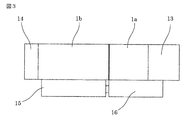
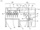
- FIG. 1 is a front view showing a gas-insulated switchgear according to Embodiment 1 of the present invention.
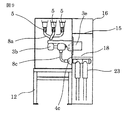
- FIG. 2 is a side view showing a gas-insulated switchgear according to Embodiment 1 of the present invention.
- FIG. 3 is a plan view showing a gas-insulated switchgear according to Embodiment 1 of the present invention.
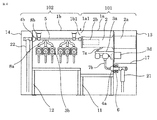
- 4 is a cross-sectional view taken along line BB of FIG. 1, showing a gas-insulated switchgear according to Embodiment 1 of the present invention.
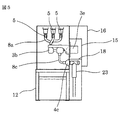
- FIG. 5 is a cross-sectional view taken along line AA of FIG. 1, showing a gas-insulated switchgear according to Embodiment 1 of the present invention.
- 6 is a single line connection diagram showing a gas insulated switchgear having the structure of FIG. 1 according to Embodiment 1 of the present invention.
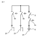
- FIG. 7 is a single line connection diagram showing a gas insulated switchgear having the structure of FIG. 8 according to Embodiment 1 of the present invention.
- FIG. 8 is a front sectional view showing a gas-insulated switchgear according to Embodiment 1 of the present invention.
- FIG. 9 is a side sectional view showing the gas insulated switchgear according to Embodiment 1 of the present invention.
- the gas-insulated switchgear 100 includes, for example, a first pressure tank 1a in which an insulating gas such as SF 6 gas, dry air, and nitrogen is sealed, and a first opening 1a1 is provided on one surface thereof.
- a circuit breaker 2 having, for example, a vacuum valve 2b therein to cut off a large current, a first disconnector 3a for connecting / disconnecting the main circuit, a first bushing 4a for connecting the main circuit to an external device,
- an insulating gas such as SF 6 gas, dry air, and nitrogen is sealed, and a second pressure tank 1b having a second opening 1b1 opposed to the first opening 1a1 on one surface thereof, and a circuit breaker 2 are connected to the front surface of the gas-insulated switchgear 100 and the three buses 5 for three phases disposed horizontally with respect to the ground, and a second one for connecting / disconnecting the main circuit with one end connected to the bus 5.
- the variable unit portion 102 including a connection conductor 8c for connecting Is configured.
- first opening 1a1 of the first pressure tank 1a and the second opening 1b1 of the second pressure tank 1b are opposed to each other and joined to form one structure. Since the first pressure tank 1a and the second pressure tank 1b are formed as a single structure and the inside thereof can be configured as one gas compartment, it is not necessary to provide an insulating spacer or the like for partitioning between them. Therefore, it is possible to obtain a gas-insulated switchgear that can be configured with a small overall outer dimension. Further, when a plurality of second disconnectors are housed in the second pressure tank, there is no partition between the disconnectors, so that the necessary insulation space between the partition and the disconnector becomes unnecessary, and overall External dimensions can be reduced.
- the first disconnector 3a and the second disconnector 3b are constituted by three-position switches that operate between three positions of connection-disconnection-grounding.
- the first pressure tank 1 a of the basic unit portion 101 is supported by the gantry 11.
- the circuit breaker operating mechanism 2a of the circuit breaker 2 and the first disconnector operating mechanism 3d of the first disconnector 3a and control parts are installed outside the first pressure tank 1a, and are stored in a storage box for protection. 13.
- the storage box 13 is also supported by the gantry 11.
- the storage box 13 is protected by covering the tank outer exposed portion of the first bushing 4a and the outer periphery of the cable terminal 21 connected to the exposed portion, and the breaker operating mechanism 2a of the cable storage location and the circuit breaker 2 is protected.
- a partition plate 17 is provided between the storage locations of the first disconnector operating mechanism 3d and the like in order to avoid the influence of an accident, and the two spaces are separated.
- annular current transformer 6 for main circuit current measurement is mounted on the outer periphery of the first bushing 4a protruding outside the first pressure tank 1a.
- the second pressure tank 1b of the variable unit 102 is supported by the gantry 12.
- the second disconnector operating mechanism 3e and the control parts of the second disconnector 3b are installed outside the tank, and are separated from the external environment of the gas insulation switchgear 100 to protect the internal structure 15 It is stored in.
- the storage box 15 is also supported by the gantry 12.
- the storage box 15 also protects the outer exposed portion of the second pressure tank 1b of the third bushing 4c and the cable terminal 23 connected to the exposed portion, and the cable storage location and the second disconnector operating mechanism 3e.
- a partition plate 18 is provided in the storage location such as the second disconnector operating mechanism 3e and the cable connecting portion.
- the bushing 4b is stored in the storage box 14 and supported by the second pressure tank 1b and the gantry 12. Yes.
- the storage box 13 and the storage box 15 are connected to the control box 16 so that a necessary control circuit can be disposed.
- the control box 16 is supported by the gantry 11.
- the rightmost circuit of FIG. 6 shows the circuit of the basic unit 101.
- Other circuits and buses connecting them in common indicate the circuit of the variable unit 102.
- the circuit of the basic unit 101 generally fulfills the function as a circuit connected to the drawing unit with this circuit.
- the circuit of the variable unit 102 varies depending on the number of circuits to which the gas-insulated switchgear 100 is externally connected, that is, the sum of the number of one drawing circuit and the number of drawing circuits, and the number of open / close devices, measuring instruments, and connecting cables. It is assumed that The shape of the storage device of the variable unit 102 and the second pressure tank 1b is changed according to the changing element.
- FIG. 7 is a single line diagram
- FIG. 8 is a front sectional view
- FIG. 9 is a side sectional view.
- FIG. 7 shows a circuit in which the number of circuits is reduced by one from FIG. 6 and the number of connection cables is changed from one to two.
- the structure of the gas insulated switchgear 100 at this time is as shown in FIGS.
- the number of cable terminals 23 is increased to two, and the second bushing 4b and the cable terminal 22 are omitted from the side sectional view of FIG.
- the basic unit part 101 can be manufactured as a standard unit in any applicable circuit. Can be produced at a reduced cost.
- connection circuit without the second disconnector 3 b of the variable unit portion 102 is directly connected to the bus 5, and there is no circuit without the second disconnector 3 b (FIG. 8).
- the second pressure tank 1b in common the types of pressure tanks can be reduced, and planned production and cost reduction can be achieved.
- the control box 16 has a structure that can accommodate a control device necessary for the maximum conditions of the application circuit of the gas-insulated switchgear 100, and is configured to be supported only by the gantry 11, so that the control box 16 can be changed even if the circuit conditions change. Can be shared, and planned production and cost reduction of the control box 16 can be achieved.
- the basic unit part 101 can be manufactured as a standard unit in any applicable circuit. Can be produced systematically, and cost reduction can be achieved.
- FIG. Embodiment 2 of the present invention will be described with reference to FIG. 10, and in each of the drawings, the same or equivalent members and parts will be described with the same reference numerals.
- 10 is a front sectional view showing a gas-insulated switchgear according to Embodiment 2 of the present invention.
- an inclined portion 1 c 2 is formed by inclining a part of the bottom surface of the first pressure tank 1 c of the basic unit portion 101 to make the first opening 1 c 1 small, and the second unit of the variable unit portion 102
- the second opening 1d1 of the pressure tank 1d is made smaller together with the first opening 1c1, and the first opening 1c1 of the first pressure tank 1c of the basic unit 101 and the second opening of the variable unit 102 are made small.
- the second opening 1d1 of the pressure tank 1d is abutted and joined.
- the gas partition space can be reduced by changing the shape of the first pressure tank 1c so as to reduce the space where there is no storage device, the amount of insulating gas used can be reduced. . Further, by reducing the first opening 1c1 and the second opening 1d1, the reliability of the hermetic seal portion is improved, and the fastening work at the time of joining the unit portions can be reduced.
- FIG. 11 is a side sectional view showing a gas insulated switchgear according to Embodiment 3 of the present invention.
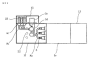
- 12 is a plan sectional view showing a gas-insulated switchgear according to Embodiment 3 of the present invention.
- the second opening 1f1 of the variable unit 102 having the second pressure tank 1f is provided in the first opening 1e1 at the rear of the basic unit 101 having the first pressure tank 1e. Butt and join together to form one component, one end is connected to one end of the circuit breaker 2 and is connected to each circuit from three buses 5 for three phases extending in the vertical direction.
- the second disconnector 3b and the third bushing 4c and the cable terminal 23 connected to the second disconnector 3b are arranged in a direction in which the circuits are stacked upward for each circuit.
- the cable terminal 22 is connected to the end of the connection conductor led leftward from one end of the circuit breaker 2 via a second bushing 4 b that is attached through the wall of the second pressure tank 1 f. Is connected.
- the main circuit branched from the second disconnector 3 b passes through the wall surface of the second pressure tank 1 f by the third bushing 4 c, and one end thereof is connected to the cable terminal 23.
- the middle part of the cable terminal 23 indicated by a round broken line indicates a cable extending downward.
- the cables for the three phases extending in the vertical direction do not interfere with each other. 3 is easily connected to the bushing 4c.
- the installation area of the gas insulated switchgear is small, such as a tower for wind power generators, for example.
- the branch main circuit connected to each line is arranged so as to be stacked in the vertical direction. Even in the area, it is possible to easily cope with line connection of a plurality of power lines.
- the present invention is not limited to this. Even if it is placed in an up-down direction (ie, diagonally) instead of vertically, the installation area increases compared to the above example, but it can easily accommodate multiple lines even in a small installation area it can.
- the first opening of the first pressure tank and the second opening of the second pressure tank are opposed to each other and joined to form one structure, and the inside of the structure is formed of one gas. It is suitable for realizing a gas-insulated switchgear that can be configured as a compartment.
Landscapes
- Engineering & Computer Science (AREA)
- Power Engineering (AREA)
- Gas-Insulated Switchgears (AREA)
Abstract
Description
以下、この発明の実施の形態1を図1から図9に基づいて説明するが、各図において、同一、または相当部材、部位については同一符号を付して説明する。図1はこの発明の実施の形態1に係わるガス絶縁スイッチギヤを示す正面図である。図2はこの発明の実施の形態1に係わるガス絶縁スイッチギヤを示す側面図である。図3はこの発明の実施の形態1に係わるガス絶縁スイッチギヤを示す平面図である。図4はこの発明の実施の形態1に係わるガス絶縁スイッチギヤを示す図1のB-B線における断面図である。図5はこの発明の実施の形態1に係わるガス絶縁スイッチギヤを示す図1のA-A線における断面図である。図6はこの発明の実施の形態1に係わる図1の構造を有するガス絶縁スイッチギヤを示す単線接続図である。図7はこの発明の実施の形態1に係わる図8の構造を有するガス絶縁スイッチギヤを示す単線接続図である。図8はこの発明の実施の形態1に係わるガス絶縁スイッチギヤを示す正面断面図である。図9はこの発明の実施の形態1に係わるガス絶縁スイッチギヤを示す側面断面図である。
この発明の実施の形態2を図10に基づいて説明するが、各図において、同一、または相当部材、部位については同一符号を付して説明する。図10はこの発明の実施の形態2に係わるガス絶縁スイッチギヤを示す正面断面図である。
この発明の実施の形態3を図11および図12に基づいて説明するが、各図において、同一、または相当部材、部位については同一符号を付して説明する。図11はこの発明の実施の形態3に係わるガス絶縁スイッチギヤを示す側面断面図である。図12はこの発明の実施の形態3に係わるガス絶縁スイッチギヤを示す平面断面図である。
Claims (7)
- 絶縁性ガスが密封され、少なくとも一面に第1の開口部が設けられた第1の圧力タンクと、前記第1の圧力タンクの内部に配置され大電流を遮断する遮断器と、前記遮断器と接続され主回路を切離する第1の断路器と、前記主回路を外部の機器と接続する第1のブッシングとから構成された基本ユニット部と、
絶縁性ガスが密封され、少なくとも一面に前記第1の開口部と相対する第2の開口部が設けられた第2の圧力タンクと、前記第2の圧力タンクの内部に配置され前記遮断器の一方側の端子に接続された母線と、前記第2の圧力タンクの壁面を貫通して前記第2の圧力タンクの内部の主回路を外部の機器と接続する第2のブッシングと、前記母線と前記第2のブッシングとの間に配置され、前記主回路を切離する一つもしくは複数の第2の断路器とから構成された可変ユニット部と、
を備え、前記基本ユニット部の前記第1の開口部と前記可変ユニット部の前記第2の開口部とを相対して接合して一つの構成体としたことを特徴とするガス絶縁スイッチギヤ。 - 前記母線は、大地に対して水平に配設したことを特徴とする請求項1に記載のガス絶縁スイッチギヤ。
- 前記母線は、大地に対して垂直に配設したことを特徴とする請求項1に記載のガス絶縁スイッチギヤ。
- 前記母線と前記第2のブッシングとの間は、直接接続するものと、前記第2の断路器を介して接続するものを任意に選択可能にしたことを特徴とする請求項1から請求項3のいずれか1項に記載のガス絶縁スイッチギヤ。
- 前記母線に接続される前記第2のブッシングを前記第2の圧力タンクの側面に配設したことを特徴とする請求項1から請求項4のいずれか1項に記載のガス絶縁スイッチギヤ。
- 前記母線に接続される前記第2のブッシングの有無にかかわらず前記第1の圧力タンクの形状を共通としたことを特徴とする請求項1から請求項5のいずれか1項に記載のガス絶縁スイッチギヤ。
- 前記基本ユニット部の前記第1の圧力タンクの底面を傾斜させて前記第1の開口部を小さくし、かつ、前記可変ユニット部の前記第2の圧力タンクの前記第2の開口部を前記第1の開口部と合わせて小さくしたことを特徴とする請求項1から請求項6のいずれか1項に記載のガス絶縁スイッチギヤ。
Priority Applications (5)
| Application Number | Priority Date | Filing Date | Title |
|---|---|---|---|
| JP2015539309A JP5921783B1 (ja) | 2015-04-02 | 2015-04-02 | ガス絶縁スイッチギヤ |
| EP15887642.5A EP3280016A4 (en) | 2015-04-02 | 2015-04-02 | Gas-insulated switchgear |
| US15/542,147 US10297987B2 (en) | 2015-04-02 | 2015-04-02 | Gas insulated switchgear |
| CN201580078395.XA CN107431338B (zh) | 2015-04-02 | 2015-04-02 | 气体绝缘开关装置 |
| PCT/JP2015/060471 WO2016157495A1 (ja) | 2015-04-02 | 2015-04-02 | ガス絶縁スイッチギヤ |
Applications Claiming Priority (1)
| Application Number | Priority Date | Filing Date | Title |
|---|---|---|---|
| PCT/JP2015/060471 WO2016157495A1 (ja) | 2015-04-02 | 2015-04-02 | ガス絶縁スイッチギヤ |
Publications (1)
| Publication Number | Publication Date |
|---|---|
| WO2016157495A1 true WO2016157495A1 (ja) | 2016-10-06 |
Family
ID=56015209
Family Applications (1)
| Application Number | Title | Priority Date | Filing Date |
|---|---|---|---|
| PCT/JP2015/060471 WO2016157495A1 (ja) | 2015-04-02 | 2015-04-02 | ガス絶縁スイッチギヤ |
Country Status (5)
| Country | Link |
|---|---|
| US (1) | US10297987B2 (ja) |
| EP (1) | EP3280016A4 (ja) |
| JP (1) | JP5921783B1 (ja) |
| CN (1) | CN107431338B (ja) |
| WO (1) | WO2016157495A1 (ja) |
Citations (4)
| Publication number | Priority date | Publication date | Assignee | Title |
|---|---|---|---|---|
| JPS56145316U (ja) * | 1980-04-01 | 1981-11-02 | ||
| JPH02290111A (ja) * | 1989-04-28 | 1990-11-30 | Mitsubishi Electric Corp | ガス絶縁形配電盤 |
| JPH09322341A (ja) * | 1996-05-31 | 1997-12-12 | Mitsubishi Electric Corp | ガス絶縁開閉装置およびガス絶縁開閉装置の組立方法 |
| WO2014125948A1 (ja) * | 2013-02-13 | 2014-08-21 | 三菱電機株式会社 | ガス絶縁スイッチギヤ |
Family Cites Families (14)
| Publication number | Priority date | Publication date | Assignee | Title |
|---|---|---|---|---|
| IN157109B (ja) | 1981-01-24 | 1986-01-18 | Brush Switchgear | |
| DE3429711A1 (de) | 1983-10-27 | 1985-05-09 | Fritz Driescher KG Spezialfabrik für Elektrizitätswerksbedarf GmbH & Co, 5144 Wegberg | Gasisolierte mittelspannungsschaltanlage |
| US5898565A (en) * | 1996-06-27 | 1999-04-27 | Mitsubishi Denki Kabushiki Kaisha | Gas insulated switchgear apparatus |
| JP2002159109A (ja) * | 2000-11-20 | 2002-05-31 | Mitsubishi Electric Corp | ガス絶縁開閉装置 |
| US7688595B2 (en) * | 2002-03-13 | 2010-03-30 | Pioneer Energy Products, Llc | Shielded cable entry ports and assemblies |
| JP4334852B2 (ja) | 2002-10-31 | 2009-09-30 | 三菱電機株式会社 | ガス絶縁スイッチギヤ |
| TWI228339B (en) * | 2002-11-06 | 2005-02-21 | Mitsubishi Electric Corp | Metal-enclosed switchgear |
| JP4237591B2 (ja) * | 2003-09-17 | 2009-03-11 | 株式会社日立製作所 | ガス絶縁開閉装置 |
| CN101981645B (zh) * | 2008-04-07 | 2013-12-11 | 三菱电机株式会社 | 真空断路器和采用该真空断路器的气体绝缘开关装置 |
| CN101741029B (zh) | 2008-11-04 | 2012-09-05 | 上海天灵开关厂有限公司 | 全充气全绝缘电缆分接箱 |
| DE212010000202U1 (de) * | 2010-01-18 | 2012-09-05 | Abb Technology Ag | Kapselungsbaustein mit Trennschaltern für eine gasisolierte Schaltanlage |
| US8451589B2 (en) * | 2010-06-07 | 2013-05-28 | Abd El & Larson Holdings LLC | Multi-access switchgear assembly |
| WO2015186244A1 (ja) * | 2014-06-06 | 2015-12-10 | 三菱電機株式会社 | スイッチギヤ |
| CN204089010U (zh) | 2014-08-22 | 2015-01-07 | Abb技术有限公司 | 多台开关柜共用母线室的气体绝缘开关柜 |
-
2015
- 2015-04-02 JP JP2015539309A patent/JP5921783B1/ja active Active
- 2015-04-02 EP EP15887642.5A patent/EP3280016A4/en active Pending
- 2015-04-02 US US15/542,147 patent/US10297987B2/en active Active
- 2015-04-02 WO PCT/JP2015/060471 patent/WO2016157495A1/ja active Application Filing
- 2015-04-02 CN CN201580078395.XA patent/CN107431338B/zh active Active
Patent Citations (4)
| Publication number | Priority date | Publication date | Assignee | Title |
|---|---|---|---|---|
| JPS56145316U (ja) * | 1980-04-01 | 1981-11-02 | ||
| JPH02290111A (ja) * | 1989-04-28 | 1990-11-30 | Mitsubishi Electric Corp | ガス絶縁形配電盤 |
| JPH09322341A (ja) * | 1996-05-31 | 1997-12-12 | Mitsubishi Electric Corp | ガス絶縁開閉装置およびガス絶縁開閉装置の組立方法 |
| WO2014125948A1 (ja) * | 2013-02-13 | 2014-08-21 | 三菱電機株式会社 | ガス絶縁スイッチギヤ |
Non-Patent Citations (1)
| Title |
|---|
| See also references of EP3280016A4 * |
Also Published As
| Publication number | Publication date |
|---|---|
| JPWO2016157495A1 (ja) | 2017-04-27 |
| EP3280016A1 (en) | 2018-02-07 |
| US20180269663A1 (en) | 2018-09-20 |
| US10297987B2 (en) | 2019-05-21 |
| JP5921783B1 (ja) | 2016-05-24 |
| CN107431338A (zh) | 2017-12-01 |
| CN107431338B (zh) | 2020-10-30 |
| EP3280016A4 (en) | 2018-11-07 |
Similar Documents
| Publication | Publication Date | Title |
|---|---|---|
| KR101286812B1 (ko) | 스위치 기어 | |
| EP3062403B1 (en) | Gas-insulated switchgear | |
| JP4512648B2 (ja) | スイッチギヤ | |
| CN101350506A (zh) | 真空绝缘开关装置 | |
| KR20120124020A (ko) | 전기 전력 스위치, 및 전력 스위치를 포함하는 제어 패널 | |
| US9472926B2 (en) | Gas-insulated switchgear arrangement | |
| EP2958205B1 (en) | Gas-insulated switchgear | |
| US10673212B2 (en) | Switchgear | |
| JP4572145B2 (ja) | ガス絶縁スイッチギヤ | |
| CN102986100A (zh) | 具有包括空气和屏栅的单相隔离的开关设备 | |
| US20130201607A1 (en) | Pressurised gas-insulated multi-phase control panel | |
| JP4744323B2 (ja) | スイッチギヤ | |
| JP5921783B1 (ja) | ガス絶縁スイッチギヤ | |
| JP6398651B2 (ja) | スイッチギヤ | |
| JP6190442B2 (ja) | ガス絶縁スイッチギヤ | |
| JP3203676U (ja) | ガス絶縁スイッチギヤ | |
| JP2009044927A (ja) | 金属閉鎖形スイッチギヤ | |
| KR102639972B1 (ko) | 가스 절연식 스위치기어를 위한 컴팩트한 회로 차단기 | |
| KR20180000846U (ko) | 배전반 | |
| JP2008086141A (ja) | スイッチギヤ | |
| JP2012231576A (ja) | ガス絶縁スイッチギヤ | |
| JP2011234463A (ja) | ガス絶縁スイッチギヤ |
Legal Events
| Date | Code | Title | Description |
|---|---|---|---|
| ENP | Entry into the national phase |
Ref document number: 2015539309 Country of ref document: JP Kind code of ref document: A |
|
| 121 | Ep: the epo has been informed by wipo that ep was designated in this application |
Ref document number: 15887642 Country of ref document: EP Kind code of ref document: A1 |
|
| WWE | Wipo information: entry into national phase |
Ref document number: 15542147 Country of ref document: US |
|
| REEP | Request for entry into the european phase |
Ref document number: 2015887642 Country of ref document: EP |
|
| NENP | Non-entry into the national phase |
Ref country code: DE |