WO2016157386A1 - 始動発電装置、及び始動発電方法 - Google Patents
始動発電装置、及び始動発電方法 Download PDFInfo
- Publication number
- WO2016157386A1 WO2016157386A1 PCT/JP2015/059997 JP2015059997W WO2016157386A1 WO 2016157386 A1 WO2016157386 A1 WO 2016157386A1 JP 2015059997 W JP2015059997 W JP 2015059997W WO 2016157386 A1 WO2016157386 A1 WO 2016157386A1
- Authority
- WO
- WIPO (PCT)
- Prior art keywords
- generator
- terminal
- power generation
- starting
- mosfets
- Prior art date
- Legal status (The legal status is an assumption and is not a legal conclusion. Google has not performed a legal analysis and makes no representation as to the accuracy of the status listed.)
- Ceased
Links
Images




Classifications
-
- F—MECHANICAL ENGINEERING; LIGHTING; HEATING; WEAPONS; BLASTING
- F02—COMBUSTION ENGINES; HOT-GAS OR COMBUSTION-PRODUCT ENGINE PLANTS
- F02N—STARTING OF COMBUSTION ENGINES; STARTING AIDS FOR SUCH ENGINES, NOT OTHERWISE PROVIDED FOR
- F02N11/00—Starting of engines by means of electric motors
- F02N11/04—Starting of engines by means of electric motors the motors being associated with current generators
-
- H—ELECTRICITY
- H02—GENERATION; CONVERSION OR DISTRIBUTION OF ELECTRIC POWER
- H02P—CONTROL OR REGULATION OF ELECTRIC MOTORS, ELECTRIC GENERATORS OR DYNAMO-ELECTRIC CONVERTERS; CONTROLLING TRANSFORMERS, REACTORS OR CHOKE COILS
- H02P9/00—Arrangements for controlling electric generators for the purpose of obtaining a desired output
- H02P9/04—Control effected upon non-electric prime mover and dependent upon electric output value of the generator
Definitions
- the present invention relates to a starting power generation device and a starting power generation method.
- This ACG starter motor includes a permanent magnet that forms a field and is designed so that the winding specifications of the armature satisfy the torque characteristics required when starting the engine (Patent Document 1 and Patent Document 2). ).
- the ACG starter motor is used as a generator as it is, and the amount of power generation exceeds the amount of power required for the electrical load, and surplus power is generated.
- a method is used in which the generated power is suppressed by short-circuit control of the semiconductor elements constituting the rectifier circuit. In this system, the current that flows back through the ACG starter motor flows through the armature winding of the ACG starter motor and the power device element that drives the ACG starter motor. As well as worsening engine friction.
- JP 2003-83209 A Japanese Patent No. 4851844 Japanese Patent No. 4329527
- the configurations described in Patent Document 1 to Patent Document 3 have the following problems.
- the armature winding is formed by four windings connected in parallel, but one of the three phases is commonly connected in all windings. Yes. That is, the winding used as the ACG starter motor and the winding used as the generator are connected to a common node and are not completely separated. The winding is selected by a relay. For this reason, the use of the relays frequently turned on and off, such as idle stop control, has a problem of reducing contact life.
- MOSFET metal oxide field effect transistor
- the relay can cut off the current in both directions by turning off the contact, but even if the MOSFET is turned off, the current flows through the parasitic diode between the drain and source, so that the current can only be cut in one direction. Can not.
- a MOSFET is used instead of a relay to separate the windings, the windings used as the ACG starter motor are not separated and the generated power is supplied from the windings of the ACG starter motor. The problem is that the power is excessively supplied and the power loss increases.
- the neutral point is controlled and can be used only when the armature winding is a star connection, and when the armature winding is a delta connection. There is a problem that it cannot be dealt with. If a combination with a delta-connected armature winding having no neutral point is considered, the number of individual relays increases, resulting in problems of high cost and complicated wiring.
- the ACG starter motor is composed of two armature windings. When used as an ACG starter motor, only one armature winding is used and used as a generator. When used, two windings are used.
- the field is configured using windings. In this configuration, a current is normally applied to the field winding using a brush. Compared with the case where the field is configured using a permanent magnet, the configuration described in Patent Document 3 is difficult to reduce the size of the device, and as shown in Patent Document 2, it can be directly attached to the crankshaft. There is a problem that it is not suitable.
- the present invention is a starter generator, and includes a starter generator having an armature part having a winding part made of a multiphase coil and a field part made of a permanent magnet, an AC terminal, and a direct current and an alternating current A plurality of switch elements that are inserted between the AC terminal and the winding part, and connect and disconnect the winding part with respect to the AC terminal. It is characterized by providing.
- the present invention is also a starting power generation method, a starting generator having an armature portion having a winding portion made of a multiphase coil, and a field portion made of a permanent magnet, an AC terminal, and a direct current And a plurality of orthogonal transform units that convert electric power bidirectionally between the AC and the AC terminal and the winding unit, and a plurality of connecting and separating the winding unit with respect to the AC terminal
- a starter generator including a switch element includes a step of controlling the plurality of switch elements to be turned on or off.
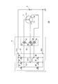
- FIG. 2 is a circuit diagram illustrating a power conversion unit 6 and a winding unit 11 illustrated in FIG. 1. It is the figure which showed an example of the electricity supply mode of the power converter part shown in FIG. It is the figure which showed an example of the flow of the electric current in the circuit diagram shown in FIG. It is the figure which showed an example of the electricity supply mode of the power converter part shown in FIG.
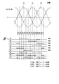
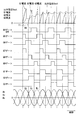
- FIG. 7 is a timing chart showing a change over time in the energization mode shown in FIG. 6.
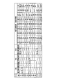
- FIG. 4 is a timing diagram illustrating an example of operation waveforms in the circuit diagram illustrated in FIG. 3. It is a characteristic view for demonstrating the operation example of the starting electric power generation control system 100 shown in FIG. It is the figure which showed an example of the electricity supply mode of the power converter part shown in FIG.
- FIG. 1 is a block diagram illustrating a configuration example of a starting power generation control system (starting power generation apparatus) 100 according to an embodiment of the present invention.
- a starting power generation control system 100 shown in FIG. 1 includes a starting generator (ACG starter motor) 1, an engine 2, a crankshaft 3, a rotation angle sensor 4, an engine water temperature gauge 5, a power converter 6, A control unit 7, a starter switch 8, and a battery 9 are included.
- the starter generator 1 is directly connected to the crankshaft 3 and rotates in synchronization with the rotation of the engine 2.
- the starter generator 1 operates as a starter motor or operates as an ACG under the control of the power conversion unit 6.
- the starter generator 1 includes a winding part 11 and a field part 15 shown in FIG.
- the winding portion 11 includes coils 11u, 11v, and 11w that constitute a star-connected three-phase coil (multi-phase coil).
- the neutral point 11 n is a neutral point of star connection constituting the winding portion 11.
- the coils 11u to 11w are armature windings wound around an armature core (not shown).
- the winding portion 11 and an armature core (not shown) constitute an armature portion.
- winding part 11 may be comprised not only by star connection but by delta connection.
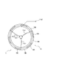
- FIG. 2 is a diagram schematically showing a configuration example of the winding portion 11 and the field portion 15 of the starter generator 1 as viewed from the axial direction. However, in FIG. 2, only the coil 11u for one phase of the three phases is shown.
- the starter generator 1 is an outer rotor type brushless motor in which the field unit 15 includes a plurality of sets of N-pole permanent magnets 15 ⁇ / b> N and S-pole permanent magnets 15 ⁇ / b> S.
- the coil 11u is composed of three windings arranged at intervals of 120 degrees with respect to an armature core (not shown). One end of each of the three windings of the coil 11u is commonly connected to the neutral point 11n, and the other end is commonly connected to the terminal 11u2.
- the engine 2 is a motor mounted on, for example, a small motorcycle.
- the crankshaft 3 is a component part of the engine 2 and is an axis that converts a reciprocating motion of a piston (not shown) included in the engine 2 into a rotational motion.
- the rotation angle sensor 4 is a sensor that detects the rotation angle (crank angle) of the crankshaft 3.
- the engine water temperature gauge 5 is a sensor that detects the temperature of the cooling water of the engine 2.
- the power conversion unit 6 includes an orthogonal conversion unit 61 and a switch unit 62.
- the orthogonal transform unit 61 includes six n-channel MOSFETs (hereinafter referred to as MOSFETs) (Q1) to (Q6), and constitutes a three-phase bridge orthogonal transform circuit.
- the orthogonal transform unit 61 connects the DC terminal 614 on the positive side (high side) of the DC input / output line to the positive electrode of the battery 9 and the DC terminal 615 on the negative side (low side) to the negative electrode of the battery 9.
- the orthogonal transform unit 61 is connected to the battery 9 and is also connected to the winding unit 11 via the switch unit 62, and performs bidirectional power conversion between AC and DC.
- the AC terminals 611, 612, and 613 of the orthogonal transform unit 61 are connected to the ends of the coils 11 u, 11 v, and 11 w of the winding unit 11 via the switch unit 62.
- the switch unit 62 includes three MOSFETs (Q7), (Q8), and (Q9).
- the coils 11u, 11v, and 11w of the winding unit 11 are connected to the AC terminals 611, 612, and 613 of the orthogonal transform unit 61, respectively. Connect to or disconnect from.
- the three MOSFETs (Q7), (Q8), and (Q9) are connected to the AC terminals 611, 612, and 613 of the orthogonal transformation unit 61 and the ends of the coils 11u, 11v, and 11w of the winding unit 11, respectively. It is inserted between the parts.
- the three MOSFETs (Q7), (Q8), and (Q9) are connected to the AC terminals 611, 612, and 613 by turning on the end portions of the coils 11u, 11v, and 11w of the winding portion 11, respectively.
- the AC terminals 611, 612, and 613 are separated from each other by being connected to each other or turned off.
- parasitic diodes D7, D8 and D9 are formed between the drain and source.
- the directions of the parasitic diodes D7, D8, and D9 are the same with respect to the AC terminals 611, 612, and 613, and the anode is connected to the AC terminals 611, 612, and 613.
- the cathode is connected to each end of each coil 11u, 11v and 11w of the winding part 11.
- the winding unit 11 via the orthogonal transformation unit 61 in the power generation operation is used. From the current to the battery 9 can be cut off.
- the directions of the parasitic diodes D7, D8, and D9 that is, the directions of the drains and sources of the MOSFETs (Q7), (Q8), and (Q9)) may be opposite to those illustrated.
- the power conversion unit 6 includes a drive circuit (not shown) for on / off control of the MOSFETs (Q1) to (Q9). This drive circuit performs on / off control of the MOSFETs (Q1) to (Q9) in accordance with a predetermined energization mode instructed by the control unit 7.
- the power converter 6 includes a sensor for detecting the current flowing through each MOSFET. For example, when the MOSFETs (Q7) to (Q9) are switched from on to off, the current flowing through the MOSFET is zero (or almost zero). ) Can be done.
- the control unit 7 shown in FIG. 1 is a device that performs ignition control and the like of the engine 2.
- the output signal of the rotation angle sensor 4, the output signal of the engine water temperature gauge 5, and the output signal of the starter switch 8 Enter.
- the control unit 7 instructs a drive circuit (not shown) included in the power conversion unit 6 about the energization mode, that is, the operation state of the MOSFETs (Q1) to (Q9).
- the control unit 7 turns on all of the MOSFETs (Q7), (Q8), and (Q9), while the starter generator 1 generates power.
- the duty ratios of the MOSFETs (Q7), (Q8), and (Q9) are changed according to the DC output voltage of the orthogonal transform unit 61.
- the control unit 7 turns on the MOSFETs (Q7), (Q8), and (Q9), while the starter / generator 1 generates power.
- each of the MOSFETs (Q7), (Q8), and (Q9) is on / off controlled based on the engine speed so as to perform either retarded angle power generation or conduction angle rectification. The retarded angle power generation and conduction angle rectification will be described later.
- the starter switch 8 is a switch operated when the user starts the engine 2.
- the battery 9 is a secondary battery.
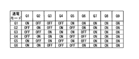
- FIG. 4 is a diagram showing an example of an energization mode of the power conversion unit 6 shown in FIG. 3 when the starter generator 1 is used as a starter motor.
- the control when the starter generator 1 is used as a starter motor is referred to as motor control.
- each energization mode shown in FIG. 4 is a case of 180 degree energization control.
- FIG. 4 shows a combination of ON (ON) or OFF (OFF) operations of the MOSFETs (Q1) to (Q9) in the power converter 6.
- FIG. 5 is a diagram illustrating a current path in the circuit diagram illustrated in FIG. 3 in the energization mode M1 illustrated in FIG.
- the control unit 7 selects one of the energization modes M1 to M6 shown in FIG. 4 and instructs the power conversion unit 6 about the selected energization mode. That is, the control unit 7 repeatedly selects one of the energization modes M1 to M6 shown in FIG. 4 according to the angle of the field unit 15 based on the output of the rotation angle sensor 4, and selects the selected energization mode each time.
- the power converter 6 is instructed.
- the MOSFETs (Q1) to (Q6) are controlled to be switched ON or OFF according to the combination of ON and OFF corresponding to the energization mode. Further, the MOSFETs (Q7) to (Q9) are all controlled to be ON.
- FIG. 5 shows a current path in the energization mode M1 shown in FIG.
- the MOSFET (Q1) is ON, (Q2) is OFF, (Q3) is OFF, (Q4) is OFF, (Q5) is ON, and (Q6) is ON. Further, MOSFETs (Q7) to (Q9) are all ON.
- FIG. 6 is a diagram illustrating an example of an energization mode of the power conversion unit 6 illustrated in FIG. 3 in the case of power generation control.
- the energization mode shown in FIG. 6 includes 12 stages of stage numbers S1 to S12. 6 is associated with the control states of the MOSFETs (Q1) to (Q9) in the power conversion unit 6 and the output states of the ends of the coils 11u, 11v, and 11w of the winding unit 11. It shows.
- the output state of the winding part 11 is indicated by the magnitude relationship between the terminal voltage of each end of each coil 11u, 11v and 11w, that is, the terminal voltage of the AC terminals 611, 612 and 613, and the polarity.
- the terminal voltages at the ends of the coils 11u, 11v, and 11w are indicated by Uv, Vv, and Wv, respectively.
- the polarity is indicated by “+” for positive and “ ⁇ ” for negative.
- the U-phase voltage relationship “Uv> Wv, Vv” of the stage S2 means that the terminal voltage of the coil 11u is larger than the terminal voltages of the coils 11v and 11w.
- control state indicates a combination of on (ON) or off (OFF) or duty control (DUTY) operations of the MOSFETs (Q1) to (Q9) in the power converter 6.
- ON or OFF means that the MOSFET is controlled to be turned on or off during the stage.
- 100% means that all four stages are on.
- 0% means that all four stages are off.
- the control unit 7 changes the duty ratio in the duty control of the MOSFETs (Q7) to (Q9) according to the DC output voltage of the orthogonal transform unit 61.
- the control unit 7 changes the duty ratio according to the comparison result between the reference value corresponding to the charging voltage of the battery 9 and the DC output voltage of the orthogonal transform unit 61 (voltage between the DC terminals 614 and 615).
- the control unit 7 increases the duty ratio when the DC output voltage of the orthogonal transform unit 61 is lower than the reference value, and decreases the duty ratio when the DC output voltage is higher than the reference value.
- control unit 7 adjusts the time continuity state of the duty ratio so that each phase of the three-phase alternating current is not biased, or adds hysteresis to the reference value so that the output voltage is not hunted. Can be set.
- the comparison target with the reference value may be, for example, the terminal voltage of the battery 9 instead of the voltage between the DC terminals 614 and 615.
- the control unit 7 selects one of the stage numbers S1 to S12 shown in FIG. 6 and instructs the power conversion unit 6 of the selected stage number. That is, the control unit 7 repeatedly selects any one of the stage numbers S1 to S12 shown in FIG. 6 according to the angle of the field unit 15 based on the output of the rotation angle sensor 4, and selects the selected stage number each time.
- the power converter 6 is instructed.
- the MOSFETs (Q1) to (Q6) are controlled by switching them on or off. Further, the MOSFETs (Q7) to (Q9) are controlled by being switched ON or OFF, or are duty controlled according to the DC output voltage of the orthogonal transform unit 61.
- FIG. 7 is a timing chart showing a time change of the energization mode shown in FIG.
- FIG. 7 shows the temporal change of the terminal voltages Uv, Vv and Wv at the respective ends of the coils 11u, 11v and 11w and the control states of the MOSFETs (Q1) to (Q9).
- ON or OFF control is indicated by a level change (H level or L level), and a duty control period is indicated by an arrow.
- MOSFETs (Q1), (Q2), (Q4), (Q6) and (Q7) are OFF, MOSFETs (Q3), (Q5) and (Q8) are ON, and MOSFET (Q9) Is the duty control state.
- FIG. 8 shows the waveform of the next part when the rotation speed (rotational speed) of the starter generator 1 is increased from 0 with the duty ratio kept constant at about 60%. That is, FIG. 8 shows the DC output voltage Vout of the orthogonal transform unit 61, the drain currents of the MOSFETs (Q1) to (Q3), the gate voltages of the MOSFETs (Q1) to (Q9), and the terminal voltages Uv, Vv and Each waveform of Wv is shown.
- a section T1 delimited by a broken line where the current of the MOSFET (Q1) first rises corresponds to the stages S2 to S5 in FIG.
- the power conversion unit 6 is interposed between the AC terminals 611 to 613 of the orthogonal conversion unit 61 and the winding unit 11, and is connected to the AC terminals 611 to 613.
- a plurality of MOSFETs (Q7) to (Q9) (switch elements) for connecting and separating the winding part 11 are provided. According to this configuration, when the generated power becomes excessive, the winding portion 11 can be disconnected, so that no reflux current can be generated. Therefore, generation of power loss due to heat generation can be prevented. Therefore, it is possible to easily improve the control characteristics of the starter generator such as reduction of power loss.
- the switching diode for disconnecting and connecting the winding portion 11 is made by making the direction of the parasitic diodes of the MOSFETs (Q7) to (Q9) the same with respect to the AC terminals 611 to 613.
- the orthogonal transform unit 61 is controlled based on the engine speed so as to be either retarded angle power generation or conduction angle rectification, and the MOSFET (Q7), Each of (Q8) and (Q9) can be on / off controlled.
- the retarded angle power generation is power generation control that turns on the MOSFETs (Q1) to (Q6) constituting the orthogonal transform unit 61 by an electrical angle of 180 degrees as shown in FIG.
- conduction angle rectification is also called conduction angle rectification, and as shown in FIGS. 6 and 7, the MOSFETs (Q1) to (Q6) constituting the orthogonal transformation unit 61 are turned on by an electrical angle of 120 degrees.
- the ON period for each phase corresponds to the period in which the voltage of each phase is the highest voltage.
- two of the three high-side MOSFETs (Q1) to (Q3) and one low-side or three low-side MOSFETs (Q4) to (Q4) to (Q3) to ( Two of Q6) and one of the high side connected to the low-side non-conduction phase are simultaneously turned on.
- conduction angle rectification a total of two MOSFETs, one of the three high-side MOSFETs (Q1) to (Q3) and one of the three low-side MOSFETs (Q4) to (Q6). Only turns on.
- the circuit of the circulating current is not formed. Therefore, when the amount of power generation becomes excessive, there is a possibility that an overvoltage is applied to the battery by a rectifier circuit composed of MOSFET parasitic diodes, but in this embodiment, MOSFETs (Q7) to (Q9) are cut off. Thus, the occurrence of overvoltage can be prevented. Further, the output of the starter generator 1 is controlled to an appropriate magnitude by duty-controlling the MOSFETs (Q7) to (Q9) according to the DC output voltage of the orthogonal transform unit 61 (that is, the charging voltage of the battery 9). Can do.
- the retarded angle power generation can increase the output of the starter generator 1 rather than the conduction angle rectification. Therefore, in the present embodiment, as shown in FIG. 9, for example, when the engine 2 is at a low speed and the starter generator 1 has an insufficient power generation amount, retarded power generation is performed. Then, power generation control by the conduction angle rectification method is performed.
- FIG. 9 is a characteristic diagram in which the horizontal axis represents the number of revolutions of the engine 2 and the vertical axis represents the electric load and the power generation amount of the starting generator 1.
- the power generation amount indicated by the chain line indicates the power generation amount when the duty control by the MOSFETs (Q7) to (Q9) is not performed, and the power generation amount indicated by the solid line is when the duty control by the MOSFETs (Q7) to (Q9) is performed. Indicates the amount of power generation.
- the amount of power generation can be controlled to an appropriate size corresponding to the electric load.
- FIG. 10 shows an energization mode in power generation control by retarded angle power generation.
- FIG. 10 shows a combination of ON (ON) or OFF (OFF) operations of the MOSFETs (Q1) to (Q9) in the power converter 6.
- the starter generator 1 (including the armature portion in which the winding portion 11 which is a three-phase coil (multi-phase coil) is disposed and the field portion made of a permanent magnet is provided.
- ACG starter motor an orthogonal transform unit 61 that performs power conversion between AC and DC, and each end of the winding unit 11 and each AC terminal 611, 612, and 613 of the orthogonal transform unit 61.
- a plurality of MOSFETs (switch elements) (Q7) to (Q9) for connecting and separating each end portion of the winding portion 11 with respect to each AC terminal 611, 612, and 613 are provided. According to this configuration, it is possible to easily improve the control characteristics of the starter generator 1 (ACG starter motor) such as reduction of power loss.
- the heat generation of the armature winding and the power device can be reduced by reducing the circulating current.
- Start-up power generation control system 1 Start-up generator 6 Power conversion unit 7 Control units D7 to D9 Parasitic diodes Q1 to Q9 MOSFET 11 Winding part 11u, 11v, 11w Coil (winding) 15 Field part 61 Orthogonal transformation part 62 Switch part 611,612,613 AC terminal
Landscapes
- Engineering & Computer Science (AREA)
- Chemical & Material Sciences (AREA)
- Combustion & Propulsion (AREA)
- Mechanical Engineering (AREA)
- General Engineering & Computer Science (AREA)
- Power Engineering (AREA)
- Control Of Eletrric Generators (AREA)
Abstract
多相コイルからなる巻線部を有する電機子部と、永久磁石からなる界磁部とを備えた始動発電機と、交流端子を有し、直流及び交流間で電力を双方向に変換する直交変換部と、前記交流端子と前記巻線部との間に介挿され、前記交流端子に対して前記巻線部の接続及び分離を行う複数のスイッチ素子とを備える。
Description
本発明は、始動発電装置、及び始動発電方法に関する。
従来、車両、特に小型二輪車などにおいては、エンジン始動時にスタータモータとして働くと共にエンジン始動後は発電機として働くACG(交流ジェネレータ)スタータモータ(始動発電機)が多用されている(例えば、特許文献1、特許文献2及び特許文献3)。
このACGスタータモータには、永久磁石で界磁を構成するとともに、電機子の巻線仕様をエンジン始動時に必要なトルク特性を満たすように設計しているものがある(特許文献1及び特許文献2)。このような構成では、ACGスタータモータがそのまま発電機として用いられる、電装負荷に必要な電力量を超えた発電量となり、余剰電力が発生してしまう。また、このようなACGスタータモータでは、整流回路を構成する半導体素子のショート制御により発電電力を抑制する方式が用いられている。この方式では、ACGスタータモータを還流する電流がACGスタータモータの電機子巻線やACGスタータモータを駆動するパワーデバイス素子を流れることにより、発熱することで電力損失が発生して車両の燃費を悪化させるとともに、エンジンフリクションも悪化させる。そのため、特許文献1及び特許文献2に記載されている構成では、ACGスタータモータの電機子巻線を並列に複数設け、ACGスタータモータとして用いられる場合と、発電機として用いられる場合とで使用する電機子巻線を切り替える制御が行われている。
しかしながら、特許文献1から特許文献3に記載されている構成には次の課題がある。まず、特許文献1に記載の構成では、電機子巻線が並列に接続された4個の巻線から形成されているが、全ての巻線において三相の内一相が共通に接続されている。すなわち、ACGスタータモータとして用いられる巻線と、発電機として用いられる巻線とが、共通の節点に接続されていて、完全には分離されていない。また、巻線の選択はリレーで行われている。そのためアイドルストップ制御のように頻繁にリレーをオン・オフする使い方では接点の寿命低下が課題となる。また、各巻線の一相が共通に接続されている構成では、リレーをMOSFET(金属酸化物電界効果トランジスタ)へ置き換える場合、次の点が課題となる。すなわち、リレーでは接点をオフすることで電流を双方向で遮断することができるが、MOSFETではオフした場合でもドレイン・ソース間の寄生ダイオードに電流が流れるため、一方向の電流しか遮断することができない。このため、巻線を分離するためにリレーでなくMOSFETを用いた場合には、ACGスタータモータとして用いられる巻線が分離されずに、ACGスタータモータの巻線から発電電力が供給されて電力が過剰供給され、電力損失が増大するということが課題となる。
また、特許文献2に記載の構成では、中性点を制御するものであり、電機子巻線がスター結線である場合にのみ使用することができ、電機子巻線がデルタ結線である場合に対応することができないという課題がある。仮に中性点が無いデルタ結線の電機子巻線との組み合わせを考えた場合、個別リレーが増加することとなり、コスト高や配線の複雑化が問題となる。
また、特許文献3に記載の構成では、ACGスタータモータが2つの電機子巻線から構成されており、ACGスタータモータとして用いられる際には一方の電機子巻線のみを用い、発電機として用いられる際には2個の巻線を用いる構成となっている。また、特許文献1及び特許文献2に記載の構成と異なり、特許文献3に記載の構成では、界磁が巻線を用いて構成されている。この構成では、通常、ブラシを用いて界磁巻線に電流が通電される。永久磁石を用いて界磁を構成する場合と比較して、特許文献3に記載の構成は、装置の小型化が難しく、特許文献2で図示されているようにクランクシャフトに直結する取り付けにも適していないという課題がある。
本発明は、上記の課題を解決することができる始動発電装置、及び始動発電方法を提供することを目的とする。
本発明は、始動発電装置であり、多相コイルからなる巻線部を有する電機子部と、永久磁石からなる界磁部とを備えた始動発電機と、交流端子を有し、直流及び交流間で電力を双方向に変換する直交変換部と、前記交流端子と前記巻線部との間に介挿され、前記交流端子に対して前記巻線部の接続及び分離を行う複数のスイッチ素子とを備えることを特徴とする。
また、本発明は、始動発電方法であり、多相コイルからなる巻線部を有する電機子部と、永久磁石からなる界磁部とを備えた始動発電機と、交流端子を有し、直流及び交流間で電力を双方向に変換する直交変換部と、前記交流端子と前記巻線部との間に介挿され、前記交流端子に対して前記巻線部の接続及び分離を行う複数のスイッチ素子とを備える始動発電装置において、前記複数のスイッチ素子をオン又はオフに制御するステップを含むことを特徴とする。
本発明によれば、電力損失の低減等、始動発電機の制御特性を容易に向上させることができる。
以下、図面を参照して本発明の実施形態について説明する。図1は、本発明の実施形態の始動発電制御システム(始動発電装置)100の構成例を示したブロック図である。図1に示した始動発電制御システム100は、始動発電機(ACGスタータモータ)1と、エンジン2と、クランクシャフト3と、回転角度センサ4と、エンジン水温計5と、電力変換部6と、制御部7と、スタータスイッチ8と、バッテリ9とを含む。
始動発電機1は、クランクシャフト3に直結されていて、エンジン2の回転に同期して回転する。始動発電機1は、電力変換部6の制御によって、スタータモータとして動作したり、ACGとして動作したりする。始動発電機1は、巻線部11と図2に示す界磁部15とを備える。巻線部11はスター結線された3相コイル(多相コイル)を構成するコイル11u、11v及び11wを備える。中性点11nは巻線部11を構成するスター結線の中性点である。コイル11u~11wは、図示してない電機子鉄心に巻かれている電機子巻線である。また、巻線部11と図示してない電機子鉄心とは電機子部を構成する。なお、巻線部11はスター結線に限らず、デルタ結線で構成されていてもよい。
図2は、始動発電機1の巻線部11及び界磁部15の構成例を軸方向から見て模式的に示した図である。ただし、図2では、3相のうちの1相分のコイル11uのみを示している。図2に示した構成例では、始動発電機1は、界磁部15を複数組のN極の永久磁石15N及びS極の永久磁石15Sから構成したアウターロータ型のブラシレスモータである。コイル11uは、図示してない電機子鉄心に対して120度おきに配設された3個の巻線から構成されている。コイル11uの3個の巻線は各一端を中性点11nに共通に接続し、各他端を端子11u2に共通に接続している。
一方、図1において、エンジン2は例えば小型二輪車に搭載された発動機である。クランクシャフト3は、エンジン2の構成部品であり、エンジン2が備える図示していないピストンの往復運動を回転運動に変換する軸である。回転角度センサ4は、クランクシャフト3の回転角度(クランク角)を検知するセンサである。エンジン水温計5は、エンジン2の冷却水の温度を検知するセンサである。
図3に示したように、電力変換部6は、直交変換部61と、スイッチ部62とを備える。直交変換部61は、6個のnチャネルMOSFET(以下、MOSFETと記す)(Q1)~(Q6)を備え、3相ブリッジ直交変換回路を構成する。直交変換部61は、直流入出力線の正側(ハイサイド)の直流端子614をバッテリ9の正極に、負側(ローサイド)の直流端子615をバッテリ9の負極に接続している。直交変換部61は、バッテリ9に接続されるとともに、スイッチ部62を介して巻線部11に接続され、交流及び直流間の双方向の電力変換を行う。また、直交変換部61の各交流端子611、612及び613には、スイッチ部62を介して、巻線部11の各コイル11u、11v及び11wの各端部が接続される。
スイッチ部62は、3個のMOSFET(Q7)、(Q8)及び(Q9)を備え、巻線部11の各コイル11u、11v及び11wをそれぞれ直交変換部61の各交流端子611、612及び613に接続したり、分離したりする。この場合、3個のMOSFET(Q7)、(Q8)及び(Q9)は、直交変換部61の各交流端子611、612及び613と、巻線部11の各コイル11u、11v及び11wの各端部との間に介挿されている。そして、3個のMOSFET(Q7)、(Q8)及び(Q9)は、巻線部11の各コイル11u、11v及び11wの各端部を、オンすることで各交流端子611、612及び613に対して接続したり、オフすることで各交流端子611、612及び613から分離したりする。
また、各MOSFET(Q7)、(Q8)及び(Q9)は、ドレイン・ソース間に寄生ダイオードD7、D8及びD9が形成されている。この場合、寄生ダイオードD7、D8及びD9の向きが各交流端子611、612及び613に対して同一であり、アノードが各交流端子611、612及び613に接続されている。また、カソードは、巻線部11の各コイル11u、11v及び11wの各端部に接続されている。このように寄生ダイオードD7、D8及びD9の向きをそろえることで、各MOSFET(Q7)、(Q8)及び(Q9)をオフした場合に、発電動作における直交変換部61を介した巻線部11からバッテリ9への電流の流れ出しを遮断することができる。なお、寄生ダイオードD7、D8及びD9の向き(すなわちMOSFET(Q7)、(Q8)及び(Q9)のドレイン及びソースの向き)は、図示したものと逆向きであってもよい。
なお、電力変換部6は、MOSFET(Q1)~(Q9)をオン・オフ制御するための図示していない駆動回路を備えている。この駆動回路は、制御部7から指示された所定の通電モードに従ってMOSFET(Q1)~(Q9)をオン・オフ制御する。また、電力変換部6は、各MOSFETに流れる電流を検出するためのセンサを備え、例えば、MOSFET(Q7)~(Q9)のオンからオフへの切替をMOSFETに流れる電流が零(あるいはほぼ零)となったときに行うことができる。
図1に示した制御部7は、エンジン2の点火制御等を行う装置であり、この場合、回転角度センサ4の出力信号と、エンジン水温計5の出力信号と、スタータスイッチ8の出力信号とを入力する。また、制御部7は、電力変換部6が備える図示していない駆動回路に対して、MOSFET(Q1)~(Q9)の通電モードすなわち動作状態を指示する。制御部7は、例えば、始動発電機1がエンジンの始動を行うスタータモータとして用いられる場合にMOSFET(Q7)、(Q8)及び(Q9)全てをオン状態とし、一方、始動発電機1が発電機として用いられる場合、直交変換部61の直流出力電圧に応じてMOSFET(Q7)、(Q8)及び(Q9)のデューティ比を変化させる。また、制御部7は、始動発電機1がエンジンの始動を行うスタータモータとして用いられる場合にMOSFET(Q7)、(Q8)及び(Q9)全てをオン状態とし、一方、始動発電機1が発電機として用いられる場合、エンジン回転数に基づき、遅角発電又は導通角整流のいずれかとなるようMOSFET(Q7)、(Q8)及び(Q9)の各々をオン・オフ制御する。遅角発電及び導通角整流については後述する。
一方、スタータスイッチ8は、ユーザがエンジン2を始動する際に操作するスイッチである。そして、バッテリ9は2次電池である。
次に、図4から図8を参照して、図3に示した始動発電機1と電力変換部6との動作例について説明する。図4は、始動発電機1がスタータモータとして用いられる場合の図3に示した電力変換部6の通電モードの一例を示した図である。以下、始動発電機1がスタータモータとして使用いられる場合の制御をモータ制御と呼ぶ。ここで、図4に示した各通電モードは、180度通電制御の場合である。図4は、電力変換部6内の各MOSFET(Q1)~(Q9)のON(オン)又はOFF(オフ)の動作の組み合わせを示している。図5は、図4に示した通電モードM1における図3に示した回路図における電流の経路を示した図である。
モータ制御の場合、制御部7は、図4に示した通電モードM1~M6の1つを選択し、選択した通電モードを電力変換部6に対して指示する。すなわち、制御部7は、回転角度センサ4の出力に基づき、界磁部15の角度に合わせて図4に示した通電モードM1~M6のいずれかを繰り返し選択し、選択した通電モードをその都度、電力変換部6に対して指示する。この場合、MOSFET(Q1)~(Q6)は通電モードに応じたON・OFFの組み合わせに従いON又はOFFに切り替えて制御される。また、MOSFET(Q7)~(Q9)はすべてONに制御される。
図5は、図4に示した通電モードM1における電流の経路を破線の矢印で示した。この場合、MOSFET(Q1)はON、(Q2)はOFF、(Q3)はOFF、(Q4)はOFF、(Q5)はON、そして(Q6)はONである。また、MOSFET(Q7)~(Q9)はすべてONである。
次に、図6から図8を参照して、始動発電機1が発電機として用いられる場合の図3に示した電力変換部6の通電モードについて説明する。以下、始動発電機1が発電機として用いられる場合の制御を発電制御と呼ぶ。図6は、発電制御の場合の図3に示した電力変換部6の通電モードの一例を示した図である。ここで、図6に示した通電モードは、ステージ番号S1~S12の12段階を含む。また、図6の図表は、電力変換部6内の各MOSFET(Q1)~(Q9)の制御状態とともに、巻線部11の各コイル11u、11v及び11wの各端部の出力状態と対応付けて示している。
図6の図表では、巻線部11の出力状態を、各コイル11u、11v及び11wの各端部の端子電圧すなわち交流端子611、612及び613の端子電圧間の大小関係と、極性とで示している。ここで、コイル11u、11v及び11wの各端部の端子電圧をそれぞれUv、Vv及びWvで示した。また、極性は、正を「+」で、そして、負を「-」で示した。例えばステージS2のU相の電圧関係「Uv>Wv,Vv」は、コイル11uの端子電圧がコイル11v及び11wの各端子電圧より大きいことを意味する。
また、制御状態は、電力変換部6内の各MOSFET(Q1)~(Q9)のオン(ON)若しくはオフ(OFF)又はデューティ制御(DUTY)の動作の組み合わせを示している。ON又はOFFは、当該ステージの期間中MOSFETがオン又はオフに固定して制御されることを意味する。DUTYは、例えば、連続する当該4つのステージにおいて、オンとなる時間の割合(=デューティ比)が0%から100%までの範囲の値となるように制御されることを意味する。ここで、100%は4ステージ分の期間すべてオンとなることを意味する。また、0%は4ステージ分の期間すべてオフとなることを意味する。
本実施形態において、制御部7は、直交変換部61の直流出力電圧に応じてMOSFET(Q7)~(Q9)のデューティ制御におけるデューティ比を変化させる。この場合、制御部7は、バッテリ9の充電電圧に対応する基準値と、直交変換部61の直流出力電圧(直流端子614及び615間の電圧)との比較結果に応じてデューティ比を変化させる。制御部7は、直交変換部61の直流出力電圧が基準値を下回った場合にデューティ比を増加させ、上回った場合にデューティ比を減少させる。その際、制御部7は、例えば、3相交流の各相に偏りが生じないようにデューティ比の時間的な継続状態を調整したり、出力電圧がハンチングしないよう基準値との比較にヒステリシスを設定したりすることができる。また、基準値との比較対象は、直流端子614及び615間の電圧に代えて、例えば、バッテリ9の端子電圧としてもよい。
発電制御の場合、制御部7は、図6に示したステージ番号S1~S12の1つを選択して、選択したステージ番号を電力変換部6に対して指示する。すなわち、制御部7は、回転角度センサ4の出力に基づき、界磁部15の角度に合わせて図6に示したステージ番号S1~S12のいずれかを繰り返し選択し、選択したステージ番号をその都度、電力変換部6に対して指示する。この場合、MOSFET(Q1)~(Q6)はON又はOFFに切り替えて制御される。また、MOSFET(Q7)~(Q9)はON又はOFFに切り替えて制御されるか、あるいは直交変換部61の直流出力電圧に応じてデューティ制御される。
次に、図7を参照して、図6に示した通電モードの各ステージS1~S12の時間変化について説明する。図7は、図6に示した通電モードの時間変化を示したタイミング図である。図7は、コイル11u、11v及び11wの各端部の端子電圧Uv、Vv及びWvの交流分の時間変化と、MOSFET(Q1)~(Q9)の制御状態とを示す。MOSFET(Q1)~(Q9)の制御状態は、ON又はOFFの制御をレベルの変化(Hレベル又はLレベル)で示し、デューティ制御の期間を矢印で示した。例えば、ステージS1では、MOSFET(Q1)、(Q2)、(Q4)、(Q6)及び(Q7)がOFF、MOSFET(Q3)、(Q5)及び(Q8)がON、そして、MOSFET(Q9)がデューティ制御状態である。
次に、図8を参照して、図3に示した回路図における動作波形の一例について説明する。図8は、デューティ比を約60%一定として始動発電機1の回転数(回転速度)を0から増加させた場合の次の部分の波形を示す。すなわち、図8は、直交変換部61の直流出力電圧Vout、MOSFET(Q1)~(Q3)の各ドレイン電流、MOSFET(Q1)~(Q9)の各ゲート電圧、及び、端子電圧Uv、Vv及びWvの各波形を示す。例えば、初めにMOSFET(Q1)の電流が立ち上がっている破線で区切られた区間T1は、図7のステージS2~S5に対応する。
以上のように、本実施形態においては、電力変換部6が、直交変換部61の交流端子611~613と巻線部11との間に介挿されていて、交流端子611~613に対して巻線部11の接続及び分離を行う複数のMOSFET(Q7)~(Q9)(スイッチ素子)を備えている。この構成によれば、発電電力が過剰となった場合に巻線部11を切り離すことができるので、還流電流を生じさせないようにすることができる。したがって、発熱による電力損失の発生を防止することができる。よって、電力損失の低減等、始動発電機の制御特性を容易に向上させることができる。
また、本実施形態によれば、MOSFET(Q7)~(Q9)の寄生ダイオードの向きを交流端子611~613に対して同一とすることで、巻線部11の切り離し及び接続のためのスイッチ素子を寄生ダイオードを有するMOSFETで構成することができる。
なお、上述したように、本実施形態においては、発電制御の場合、エンジン回転数に基づき、遅角発電又は導通角整流のいずれかとなるよう直交変換部61を制御するとともに、MOSFET(Q7)、(Q8)及び(Q9)の各々をオン・オフ制御することができる。ここで、遅角発電とは、図10に示したように、直交変換部61を構成するMOSFET(Q1)~(Q6)を電気角で180度分オンさせる発電制御である。一方、導通角整流とは、通電角整流とも呼ばれ、図6及び図7に示したように、直交変換部61を構成するMOSFET(Q1)~(Q6)を電気角で120度分オンさせる発電制御である。その際、相毎のオン期間は各相の電圧が最も高い電圧となる期間に対応する。遅角発電ではハイサイドの3個のMOSFET(Q1)~(Q3)のうちの2個とハイサイドの非通電相に接続されるローサイドの1個又はローサイドの3個のMOSFET(Q4)~(Q6)のうちの2個とローサイドの非通電相に接続されるハイサイドの1個が同時にオンする。他方、導通角整流では、ハイサイドの3個のMOSFET(Q1)~(Q3)のうちの1個とローサイドの3個のMOSFET(Q4)~(Q6)のうちの1個との合計2個がオンするだけである。したがって、導通角整流では、環流電流の回路が形成されない。そのため、発電量が過剰となった場合、MOSFETの寄生ダイオードで構成される整流回路によってバッテリに過電圧が印加される可能性があるが、本実施形態ではMOSFET(Q7)~(Q9)を遮断することで過電圧の発生を防止することができる。また、直交変換部61の直流出力電圧(すなわちバッテリ9の充電電圧)に応じてMOSFET(Q7)~(Q9)をデューティ制御することで始動発電機1の出力を適切な大きさに制御することができる。
なお、直交変換部61の出力電圧がバッテリ9の電圧を超えない場合、導通角整流よりも、遅角発電の方が始動発電機1の出力を大きくすることができる。そこで、本実施形態では、図9に示したように、例えばエンジン2が低回転時で始動発電機1の発電量が不足となるとき遅角発電を行い、中高回転時で発電量が過剰となるとき導通角整流方式による発電制御を行う。
なお、図9は、横軸をエンジン2の回転数、縦軸を電気負荷及び始動発電機1の発電量とする特性図である。鎖線で示した発電量はMOSFET(Q7)~(Q9)によるデューティ制御を行わない場合の発電量を示し、実線で示した発電量はMOSFET(Q7)~(Q9)によるデューティ制御を行った場合の発電量を示す。本実施形態によるデューティ制御を行うことで、発電量を電気負荷に見合った適切な大きさに制御することができる。
また、図10は、遅角発電による発電制御における通電モードを示す。図10は、電力変換部6内の各MOSFET(Q1)~(Q9)のON(オン)又はOFF(オフ)の動作の組み合わせを示している。
以上のように、本実施形態は、3相コイル(多相コイル)である巻線部11が配設された電機子部と、永久磁石からなる界磁部とを備えた始動発電機1(ACGスタータモータ)と、交流及び直流間の電力変換を行う直交変換部61と、巻線部11の各端部と直交変換部61の各交流端子611、612及び613との間に介挿され、各交流端子611、612及び613に対して巻線部11の各端部の接続及び分離を行う複数のMOSFET(スイッチ素子)(Q7)~(Q9)とを備えることを特徴とする。この構成によれば、電力損失の低減等、始動発電機1(ACGスタータモータ)の制御特性を容易に向上させることができる。
また、環流電流を減らすことで電機子巻線とパワーデバイスの発熱を低減することができる。
なお、本発明の実施形態は上記のものに限定されず、発明の要旨を逸脱しない範囲の設計等も含まれる。
100 始動発電制御システム
1 始動発電機
6 電力変換部
7 制御部
D7~D9 寄生ダイオード
Q1~Q9 MOSFET
11 巻線部
11u、11v、11w コイル(巻線)
15 界磁部
61 直交変換部
62 スイッチ部
611、612、613 交流端子
1 始動発電機
6 電力変換部
7 制御部
D7~D9 寄生ダイオード
Q1~Q9 MOSFET
11 巻線部
11u、11v、11w コイル(巻線)
15 界磁部
61 直交変換部
62 スイッチ部
611、612、613 交流端子
Claims (5)
- 多相コイルからなる巻線部を有する電機子部と、永久磁石からなる界磁部とを備えた始動発電機と、
交流端子を有し、直流及び交流間で電力を双方向に変換する直交変換部と、
前記交流端子と前記巻線部との間に介挿され、前記交流端子に対して前記巻線部の接続及び分離を行う複数のスイッチ素子と
を備えることを特徴とする始動発電装置。 - 前記複数のスイッチ素子がそれぞれMOSFETであり、当該複数のMOSFETの寄生ダイオードの向きが前記交流端子に対して同一である
ことを特徴とする請求項1に記載の始動発電装置。 - 前記直交変換部と前記複数のスイッチ素子との制御を行う制御部がさらに設けられ、
前記制御部が、前記始動発電機がエンジンの始動を行うスタータモータとして用いられる場合に前記スイッチ素子全てをオン状態とし、一方、前記始動発電機が発電機として用いられる場合、前記直交変換部の直流出力電圧に応じて前記複数のスイッチ素子のデューティ比を変化させる
ことを特徴とする請求項1又は請求項2に記載の始動発電装置。 - 前記制御部が、前記始動発電機がエンジンの始動を行うスタータモータとして用いられる場合に前記スイッチ素子全てをオン状態とし、一方、前記始動発電機が発電機として用いられる場合、エンジン回転数に基づき、遅角発電又は導通角整流のいずれかとなるよう前記直交変換部を制御するとともに前記スイッチ素子の各々をオン・オフ制御する
ことを特徴とする請求項1から3のいずれか1項に記載の始動発電装置。 - 多相コイルからなる巻線部を有する電機子部と、永久磁石からなる界磁部とを備えた始動発電機と、
交流端子を有し、直流及び交流間で電力を双方向に変換する直交変換部と、
前記交流端子と前記巻線部との間に介挿され、前記交流端子に対して前記巻線部の接続及び分離を行う複数のスイッチ素子と
を備える始動発電装置において、
前記複数のスイッチ素子をオン又はオフに制御するステップを含む
ことを特徴とする始動発電方法。
Priority Applications (1)
| Application Number | Priority Date | Filing Date | Title |
|---|---|---|---|
| PCT/JP2015/059997 WO2016157386A1 (ja) | 2015-03-30 | 2015-03-30 | 始動発電装置、及び始動発電方法 |
Applications Claiming Priority (1)
| Application Number | Priority Date | Filing Date | Title |
|---|---|---|---|
| PCT/JP2015/059997 WO2016157386A1 (ja) | 2015-03-30 | 2015-03-30 | 始動発電装置、及び始動発電方法 |
Publications (1)
| Publication Number | Publication Date |
|---|---|
| WO2016157386A1 true WO2016157386A1 (ja) | 2016-10-06 |
Family
ID=57005318
Family Applications (1)
| Application Number | Title | Priority Date | Filing Date |
|---|---|---|---|
| PCT/JP2015/059997 Ceased WO2016157386A1 (ja) | 2015-03-30 | 2015-03-30 | 始動発電装置、及び始動発電方法 |
Country Status (1)
| Country | Link |
|---|---|
| WO (1) | WO2016157386A1 (ja) |
Citations (3)
| Publication number | Priority date | Publication date | Assignee | Title |
|---|---|---|---|---|
| JP2001025175A (ja) * | 1999-07-05 | 2001-01-26 | Shindengen Electric Mfg Co Ltd | 多出力バッテリ充電装置 |
| JP2002119095A (ja) * | 2000-10-11 | 2002-04-19 | Honda Motor Co Ltd | 同期発電機の出力制御装置 |
| WO2013140906A1 (ja) * | 2012-03-22 | 2013-09-26 | 日立オートモティブシステムズ株式会社 | 電力変換装置、電動パワーステアリングシステム、電気自動車、電子制御スロットル、電動ブレーキ |
-
2015
- 2015-03-30 WO PCT/JP2015/059997 patent/WO2016157386A1/ja not_active Ceased
Patent Citations (3)
| Publication number | Priority date | Publication date | Assignee | Title |
|---|---|---|---|---|
| JP2001025175A (ja) * | 1999-07-05 | 2001-01-26 | Shindengen Electric Mfg Co Ltd | 多出力バッテリ充電装置 |
| JP2002119095A (ja) * | 2000-10-11 | 2002-04-19 | Honda Motor Co Ltd | 同期発電機の出力制御装置 |
| WO2013140906A1 (ja) * | 2012-03-22 | 2013-09-26 | 日立オートモティブシステムズ株式会社 | 電力変換装置、電動パワーステアリングシステム、電気自動車、電子制御スロットル、電動ブレーキ |
Similar Documents
| Publication | Publication Date | Title |
|---|---|---|
| US6787931B2 (en) | Starter generator for internal combustion engine | |
| JP5855128B2 (ja) | 電力変換装置および電力変換装置の制御方法 | |
| EP3358741B1 (en) | Starter-generator device and starter-generator method | |
| CN105281627B (zh) | 具有负载突降保护的旋转电机 | |
| US10027252B2 (en) | Rotating electric machine system | |
| JP2017221079A (ja) | 動力出力装置 | |
| JP6120472B2 (ja) | 始動発電装置、及び始動発電方法 | |
| JP5488265B2 (ja) | 車両用発電機 | |
| JP6128721B2 (ja) | 始動発電装置、及び始動発電方法 | |
| WO2016157386A1 (ja) | 始動発電装置、及び始動発電方法 | |
| JP6119531B2 (ja) | 車両用回転電機 | |
| WO2016157381A1 (ja) | 始動発電装置、及び始動発電方法 | |
| JP6645405B2 (ja) | 回転電機の制御装置、回転電機ユニット | |
| US9712100B2 (en) | Electric rotating machine and control method therefor | |
| JP6406143B2 (ja) | 車両用回転電機 | |
| JP6157042B1 (ja) | 始動発電装置および始動発電方法 | |
| JP2019213246A (ja) | 回転電機の制御装置 | |
| JP2013070564A (ja) | オルタネータおよびレクチファイヤ |
Legal Events
| Date | Code | Title | Description |
|---|---|---|---|
| 121 | Ep: the epo has been informed by wipo that ep was designated in this application |
Ref document number: 15887539 Country of ref document: EP Kind code of ref document: A1 |
|
| NENP | Non-entry into the national phase |
Ref country code: DE |
|
| 122 | Ep: pct application non-entry in european phase |
Ref document number: 15887539 Country of ref document: EP Kind code of ref document: A1 |
|
| NENP | Non-entry into the national phase |
Ref country code: JP |