WO2016157286A1 - 撮像装置及び撮像方法 - Google Patents
撮像装置及び撮像方法 Download PDFInfo
- Publication number
- WO2016157286A1 WO2016157286A1 PCT/JP2015/059597 JP2015059597W WO2016157286A1 WO 2016157286 A1 WO2016157286 A1 WO 2016157286A1 JP 2015059597 W JP2015059597 W JP 2015059597W WO 2016157286 A1 WO2016157286 A1 WO 2016157286A1
- Authority
- WO
- WIPO (PCT)
- Prior art keywords
- imaging
- radiation
- unit
- rays
- imaging device
- Prior art date
- Legal status (The legal status is an assumption and is not a legal conclusion. Google has not performed a legal analysis and makes no representation as to the accuracy of the status listed.)
- Ceased
Links
Images





Classifications
-
- A—HUMAN NECESSITIES
- A61—MEDICAL OR VETERINARY SCIENCE; HYGIENE
- A61B—DIAGNOSIS; SURGERY; IDENTIFICATION
- A61B6/00—Apparatus or devices for radiation diagnosis; Apparatus or devices for radiation diagnosis combined with radiation therapy equipment
- A61B6/02—Arrangements for diagnosis sequentially in different planes; Stereoscopic radiation diagnosis
- A61B6/025—Tomosynthesis
-
- H—ELECTRICITY
- H05—ELECTRIC TECHNIQUES NOT OTHERWISE PROVIDED FOR
- H05G—X-RAY TECHNIQUE
- H05G1/00—X-ray apparatus involving X-ray tubes; Circuits therefor
- H05G1/08—Electrical details
- H05G1/26—Measuring, controlling or protecting
- H05G1/30—Controlling
- H05G1/52—Target size or shape; Direction of electron beam, e.g. in tubes with one anode and more than one cathode
Definitions
- the present invention relates to an imaging apparatus and an imaging method.
- Patent Document 1 describes an example of X-ray CT (Computed Tomography).
- an object is disposed between a radiation unit that emits X-rays and a detection unit that detects X-rays.
- the object is placed on a rotatable stage and is rotatable.
- the rotation axis of the object is directed in a direction orthogonal to the plane intersecting each of the radiation unit and the detection unit.
- the object can be irradiated with X-rays from a plurality of different directions by rotating the object.
- the image of the cross section which the target object has in the above-mentioned plane is obtained by processing the image imaged when X-rays are irradiated to the target object from each direction.
- X-rays may be irradiated to an object from a plurality of different directions along a plane intersecting the object.
- image processing requires complicated calculations.
- An example of a problem to be solved by the present invention is to simplify image processing for obtaining a cross-sectional image of an object in imaging using X-rays.
- the invention described in claim 1 A radiation portion that selectively emits X-rays from each of a plurality of radiation positions arranged along the first surface; An imaging unit that captures X-rays at each of a plurality of imaging positions disposed along a second surface facing the first surface; A control unit that controls the radiation unit and the imaging unit to select the radiation position that radiates the X-ray and the imaging position that images the X-ray; With An object to be imaged is disposed between the radiation unit and the imaging unit, The said control part is an imaging device which controls the said radiation
- the invention according to claim 12 A radiation portion that selectively emits X-rays from each of a plurality of radiation positions arranged along the first surface; An imaging unit that captures X-rays at each of a plurality of imaging positions disposed along a second surface facing the first surface; Prepare An object to be imaged is disposed between the radiation unit and the imaging unit, By controlling the radiation unit and the imaging unit, the radiation position for emitting the X-ray and the imaging position for imaging the X-ray are selected, and the selected radiation position and the selected imaging position are connected. In this imaging method, virtual straight lines intersect at the object.
- FIG. 1 is a diagram illustrating a configuration of an imaging apparatus according to a first embodiment.
- 6 is a diagram illustrating a configuration of an imaging apparatus according to Embodiment 2.
- control unit 30, the image processing unit 40, and the image selection unit 42 are functional unit blocks, not hardware unit configurations.
- the control unit 30, the image processing unit 40, and the image selection unit 42 are hardware components such as a CPU of any computer, a memory, a program loaded in the memory, a storage medium such as a hard disk for storing the program, and a network connection interface. It is realized by any combination of software and software. There are various modifications of the implementation method and apparatus.
- FIG. 1 is a diagram illustrating a configuration of an imaging apparatus according to the embodiment.
- the imaging apparatus includes a radiation unit 10, an imaging unit 20, and a control unit 30.
- the radiation unit 10 selectively emits X-rays from each of a plurality of radiation positions RP arranged along a radiation surface 12 (first surface) that is a plane.
- the imaging unit 20 captures X-rays at each of a plurality of imaging positions IP arranged along a planar imaging surface 22 (second surface).
- the imaging surface 22 faces the radiation surface 12.
- the control unit 30 controls the radiation unit 10 and the imaging unit 20 to select a radiation position RP that emits X-rays and an imaging position IP that images X-rays.
- An object 50 to be imaged is arranged between the radiation unit 10 and the imaging unit 20.
- the control unit 30 controls the radiation unit 10 and the imaging unit 20 so that a virtual line connecting the selected radiation position RP and the selected imaging position IP intersects with the object 50. Details will be described below.
- the radiation surface 12 and the imaging surface 22 are planes facing each other, more specifically, planes parallel to each other.
- the shape of each of the radiation surface 12 and the imaging surface 22 is not limited to a plane.
- at least one of the radiation surface 12 and the imaging surface 22 may be curved.
- the radiation surface 12 and the imaging surface 22 may be parallel to each other or may not be parallel to each other.
- one of the radiation surface 12 and the imaging surface 22 may be inclined with respect to the other.
- An object 50 is disposed between the radiation surface 12 and the imaging surface 22.
- the imaging device images a cross section of the object 50 using X-rays.
- the object 50 is imaged of a cross section intersecting with the focus surface 52.
- the focus surface 52 is located between the radiation surface 12 and the imaging surface 22 and is parallel to the radiation surface 12 and the imaging surface 22.
- the radiation unit 10 has a radiation element 100.
- the radiation element 100 can emit X-rays from each of the plurality of radiation positions RP.
- the control unit 30 selects the radiation position RP by controlling the position (radiation point 102 in the figure) where the radiation element 100 emits X-rays.
- X-rays are emitted in the order of radiation positions RP1, RP2, RP3 from radiation positions RP1, RP2, RP3 aligned on a straight line extending along the radiation surface 12.
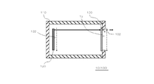
- FIG. 2 is a diagram illustrating an example of the configuration of the radiation unit 10 (radiation element 100) illustrated in FIG.
- emission part 10 (radiation element 100) is not limited to the example shown in this figure.
- the radiation unit 10 (radiation element 100) includes a container 110, an electron source 120, and an X-ray target 130.
- the container 110 has a space inside and has an opening connected to the space.
- the X-ray target 130 is disposed so as to close the opening of the container 110 described above. Thereby, the above-described space of the container 110 is blocked from the external region by the inner wall of the container 110 and the X-ray target 130. And this space of the container 110 is in a vacuum state. In the example shown in the figure, the X-ray target 130 closes the opening from the inner wall side of the container 110.
- the electron source 120 is provided in the space inside the container 110.
- the electron source 120 can emit electrons from each of a plurality of regions (for example, a plurality of lattice points of m rows and n columns) arranged two-dimensionally on the emission surface 122.
- Such electrons may be emitted by scanning a surface electron source (for example, an electron source using carbon nanotubes, a Spindt-type electron source, or an electron source using HEED (High-efficiency Electron Emission Device)). it can.
- a plurality of electron guns may be arranged two-dimensionally.
- the X-ray target 130 faces the radiation surface 122 of the electron source 120.
- An acceleration voltage for accelerating electrons from the electron source 120 is applied to the space inside the container 110. Thereby, the electrons emitted from the emission surface 122 are accelerated by the acceleration voltage and collide with the X-ray target 130.
- the X-ray target 130 emits X-rays from the surface (radiation surface 12) opposite to the surface on which the electrons collide.
- the radiation point 102 is a position where the X-ray target 130 radiates X-rays.
- the electron source 120 scans the X-ray target 130 with electrons emitted from the emission surface 122. Thereby, the radiation point 102 can be moved along the radiation surface 12.
- the X-ray target 130 is formed using, for example, copper or tungsten.
- the imaging unit 20 has an imaging element 200.
- the image sensor 200 can capture X-rays at each of a plurality of imaging positions IP.
- the control unit 30 selects the imaging position IP by controlling the position (imaging area 202 in the figure) where the imaging element 200 captures X-rays.
- the imaging device 200 has, for example, a CCD (Charge-Coupled Device) over the entire imaging surface 22, the control unit 30 selects the imaging position IP by controlling the imaging range of the CCD.
- X-rays are imaged in the order of the imaging positions IP1, IP2, and IP3 at the imaging positions IP1, IP2, and IP3 arranged on a straight line extending along the imaging surface 22.
- the radiation point 102 and the imaging region 202 are moving in opposite directions.
- the imaging position IP2 when X-rays are emitted from the radiation position RP2, the X-rays are imaged at the imaging position IP2.
- the X-rays are imaged at the imaging position IP3.
- a straight line connecting the radiation position RP1 and the imaging position IP1, a straight line connecting the imaging position IP2 and the radiation position RP2, and a straight line connecting the radiation position RP3 and the imaging position IP3 are one point on the focus plane 52 (in FIG. In the region 502).
- FIG. 3 is a diagram for explaining a method of imaging the object 50 shown in FIG.
- images 212, 214, and 216 corresponding to the areas 502, 504, and 506 of the object 50 are captured at the imaging position IP ⁇ b> 2 (FIG. 1) of the imaging unit 20.
- the regions 502, 504, and 506 of the object 50 are located on a straight line connecting the radiation position RP2 and the imaging position IP2. For this reason, the images 212, 214, and 216 overlap each other at the imaging position IP2.
- an image 212 corresponding to the region 502 of the object 50 is captured at the center of the imaging position IP1 (FIG. 1) of the imaging unit 20.
- the imaging position IP1 FIG. 1
- straight lines from the imaging position IP1 to the regions 502, 504, and 506 extend in different directions. For this reason, the image 214 and the image 216 are shifted from the image 212 at the imaging position IP1.
- an image 212 corresponding to the region 502 of the object 50 is captured at the center of the imaging position IP3 (FIG. 1) of the imaging unit 20.
- the imaging position IP3 As shown in FIG. 1, straight lines from the imaging position IP3 toward the regions 502, 504, and 506 extend in different directions. For this reason, the image 214 and the image 216 are shifted from the image 212 at the imaging position IP3.
- FIGS. 3B and 3C when the image 212 is used as a reference, the image 214 at the imaging position IP1 and the image 214 at the imaging position IP3 are located on the opposite sides of each other and the imaging position. The image 216 at IP1 and the image 216 at the imaging position IP3 are located on the opposite sides.
- the X-ray images captured at the imaging positions IP1, IP2, and IP3 are read out to the image processing unit 40. Then, the image processing unit 40 superimposes these X-ray images.
- the image 212 is located at the center of the imaging position IP at any imaging position IP.
- the image 214 at the imaging position IP1 and the image 214 at the imaging position IP3 are positioned on opposite sides.
- the image 216 at the imaging position IP1 and the image 216 at the imaging position IP3 are located on the opposite sides.
- the intensity of the signal corresponding to the image 212 is higher than the intensity of the signal corresponding to each of the image 214 and the image 216.
- the image 214 and the image 216 are blurred, but the image 212 appears clearly. In this way, the cross section of the object 50 on the focus surface 52 can be clearly imaged using X-rays.
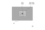
- FIG. 4 is a diagram for explaining a method of imaging the object 50 shown in FIG.
- the object 50 is scanned two-dimensionally by X-rays.
- the radiation point 102 of the radiation unit 10 is moved two-dimensionally along the radiation surface 12.
- the imaging region 202 of the imaging unit 20 is moved two-dimensionally along the imaging surface 22, and as shown in FIG.
- the corresponding image 212 appears clearly in the image.
- the image 214 and the image 216 corresponding to the region 504 and the region 506, which are shifted from the focus surface 52 are blurred.
- FIG. 5 is a diagram showing a first modification of FIG.
- the radiating unit 10 includes a radiating element 100 (for example, an electron gun) that can move along the radiating surface 12.
- the control unit 30 selects the radiation position RP by controlling the position of the radiation element 100.
- FIG. 6 is a diagram showing a second modification of FIG.
- the imaging unit 20 has an imaging element 200 that can move along the imaging surface 22.
- the control unit 30 selects the imaging position IP by controlling the position of the imaging element 200.
- FIG. 7 is a diagram showing a third modification of FIG.
- the imaging unit 20 includes an imaging element 200 and an image selection unit 42.
- the imaging device 200 captures X-rays at each of a plurality of imaging positions IP and generates image data.
- the image selection unit 42 selects a range for reading image data.
- the control unit 30 selects the imaging position IP by controlling the range in which the image selection unit 42 reads image data. Specifically, when the imaging element 200 has, for example, a CCD on the entire imaging surface 22, the control unit 30 selects the imaging position IP by controlling a range in which image data generated by the CCD is read.
- the image processing unit 40 reads out X-rays at each of a plurality of imaging positions IP from the image selection unit 42 as shown in FIGS. 3 (a) to 3 (c). Then, as illustrated in FIG. 3D, the image processing unit 40 obtains a cross-sectional image of the object 50 by superimposing these X-rays.
- the control unit 30 controls the radiation unit 10 and the imaging unit 20 to select the radiation position RP that emits X-rays and the imaging position IP that images X-rays.
- the control unit 30 controls the radiation unit 10 and the imaging unit 20 so that a straight line connecting the selected radiation position RP and the selected imaging position IP intersects with the object 50.
- the image processing unit 40 superimposes the X-rays imaged at each imaging position IP. Thereby, the cross section which the target object 50 has in the focus surface 52 can be imaged.
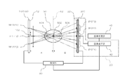
- FIG. 8 is a diagram illustrating the configuration of the imaging apparatus according to the first embodiment, and corresponds to FIG. 1 of the embodiment.
- the imaging apparatus according to the present example has the same configuration as the imaging apparatus according to the embodiment except for the following points.
- a stage 54 is disposed between the radiation unit 10 and the imaging unit 20.
- An object 50 is placed on the stage 54.
- the stage 54 is movable by the drive unit 32.
- the drive unit 32 is controlled by the control unit 30.
- the stage 54 can move in both the direction approaching the radiation unit 10 and the direction approaching the imaging unit 20.
- the ratio (A / B) of the distance A between the radiation surface 12 and the focus surface 52 and the distance B between the imaging surface 22 and the focus surface 52 can be changed.
- the imaging magnification of the imaging device can be changed.
- the X-rays radiated from the radiation position RP spread radially.
- the imaging magnification of the imaging device is (A + B) / A.
- the unit 20 is controlled.
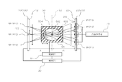
- FIG. 9 is a diagram illustrating a configuration of the imaging apparatus according to the second embodiment, and corresponds to FIG. 8 of the first embodiment.
- the imaging apparatus according to the present embodiment has the same configuration as the imaging apparatus according to the first embodiment except for the following points.
- the radiation unit 10 and the imaging unit 20 are movable by a drive unit 32.
- the radiating unit 10 and the imaging unit 20 can move both in a direction approaching the object 50 and in a direction away from the object 50.
- the ratio (A / B) of the distance A between the radiation surface 12 and the focus surface 52 and the distance B between the imaging surface 22 and the focus surface 52 can be changed.
- the imaging magnification of the imaging device can be changed.
Landscapes
- Health & Medical Sciences (AREA)
- Life Sciences & Earth Sciences (AREA)
- Medical Informatics (AREA)
- Engineering & Computer Science (AREA)
- General Health & Medical Sciences (AREA)
- Radiology & Medical Imaging (AREA)
- Heart & Thoracic Surgery (AREA)
- Nuclear Medicine, Radiotherapy & Molecular Imaging (AREA)
- Optics & Photonics (AREA)
- Pathology (AREA)
- Physics & Mathematics (AREA)
- Biomedical Technology (AREA)
- High Energy & Nuclear Physics (AREA)
- Molecular Biology (AREA)
- Surgery (AREA)
- Animal Behavior & Ethology (AREA)
- Biophysics (AREA)
- Public Health (AREA)
- Veterinary Medicine (AREA)
- Toxicology (AREA)
- Analysing Materials By The Use Of Radiation (AREA)
Abstract
放射部(10)は、平面である放射面(12)に沿って配置された複数の放射位置(RP)それぞれから選択的にX線を放射する。撮像部(20)は、平面である撮像面(22)に沿って配置された複数の撮像位置(IP)それぞれでX線を撮像する。撮像面(22)は、放射面(12)に対向している。制御部(30)は、放射部(10)及び撮像部(20)を制御することにより、X線を放射する放射位置(RP)及びX線を撮像する撮像位置(IP)を選択する。放射部(10)と撮像部(20)の間には、撮像すべき対象物(50)が配置されている。制御部(30)は、選択した放射位置(RP)及び選択した撮像位置(IP)を結ぶ仮想的な直線が対象物(50)で交わるように、放射部(10)及び撮像部(20)を制御する。
Description
本発明は、撮像装置及び撮像方法に関する。
近年、X線を用いた撮像装置が開発されている。例えば、特許文献1には、X線CT(Computed Tomography)の一例が記載されている。この例では、X線を放射する放射部とX線を検出する検出部の間に対象物が配置される。対象物は、回転可能なステージに載せられており、回転可能になっている。対象物の回転軸は、放射部及び検出部それぞれに交わる平面に直交する方向を向いている。この例では、対象物を回転させることにより、互いに異なる複数の方向から対象物にX線を照射することができる。そして各方向から対象物にX線を照射した場合に撮像された画像を処理することにより、対象物が上記した平面に有する断面の画像を得る。
X線を用いた撮像装置では、例えば、特許文献1に記載されているように、対象物に交わる平面に沿って互いに異なる複数の方向から対象物にX線を照射することがある。この場合、各方向から対象物にX線を照射した場合に撮像された画像を処理することにより、対象物が上記した平面に有する断面の画像を得ることができる。しかしながら、そのような画像処理には、複雑な計算が必要となる。
本発明が解決しようとする課題としては、X線を用いた撮像において、対象物の断面の画像を得るための画像処理を簡易なものにすることが一例として挙げられる。
請求項1に記載の発明は、
第1面に沿って配置された複数の放射位置それぞれから選択的にX線を放射する放射部と、
前記第1面に対向する第2面に沿って配置された複数の撮像位置それぞれでX線を撮像する撮像部と、
前記放射部及び前記撮像部を制御することにより、前記X線を放射する前記放射位置及び前記X線を撮像する前記撮像位置を選択する制御部と、
を備え、
前記放射部と前記撮像部の間には、撮像すべき対象物が配置され、
前記制御部は、選択した前記放射位置及び選択した前記撮像位置を結ぶ仮想的な直線が前記対象物で交わるように、前記放射部及び前記撮像部を制御する撮像装置である。
第1面に沿って配置された複数の放射位置それぞれから選択的にX線を放射する放射部と、
前記第1面に対向する第2面に沿って配置された複数の撮像位置それぞれでX線を撮像する撮像部と、
前記放射部及び前記撮像部を制御することにより、前記X線を放射する前記放射位置及び前記X線を撮像する前記撮像位置を選択する制御部と、
を備え、
前記放射部と前記撮像部の間には、撮像すべき対象物が配置され、
前記制御部は、選択した前記放射位置及び選択した前記撮像位置を結ぶ仮想的な直線が前記対象物で交わるように、前記放射部及び前記撮像部を制御する撮像装置である。
請求項12に記載の発明は、
第1面に沿って配置された複数の放射位置それぞれから選択的にX線を放射する放射部と、
前記第1面に対向する第2面に沿って配置された複数の撮像位置それぞれでX線を撮像する撮像部と、
を準備し、
撮像すべき対象物を前記放射部と前記撮像部の間に配置し、
前記放射部及び前記撮像部を制御することにより、前記X線を放射する前記放射位置及び前記X線を撮像する前記撮像位置を選択し、かつ選択した前記放射位置及び選択した前記撮像位置を結ぶ仮想的な直線が前記対象物で交わるようにする、撮像方法である。
第1面に沿って配置された複数の放射位置それぞれから選択的にX線を放射する放射部と、
前記第1面に対向する第2面に沿って配置された複数の撮像位置それぞれでX線を撮像する撮像部と、
を準備し、
撮像すべき対象物を前記放射部と前記撮像部の間に配置し、
前記放射部及び前記撮像部を制御することにより、前記X線を放射する前記放射位置及び前記X線を撮像する前記撮像位置を選択し、かつ選択した前記放射位置及び選択した前記撮像位置を結ぶ仮想的な直線が前記対象物で交わるようにする、撮像方法である。
上述した目的、およびその他の目的、特徴および利点は、以下に述べる好適な実施の形態、およびそれに付随する以下の図面によってさらに明らかになる。
以下、本発明の実施の形態について、図面を用いて説明する。尚、すべての図面において、同様な構成要素には同様の符号を付し、適宜説明を省略する。
なお、以下に示す説明において、制御部30、画像処理部40、及び画像選択部42は、ハードウエア単位の構成ではなく、機能単位のブロックを示している。制御部30、画像処理部40、及び画像選択部42は、任意のコンピュータのCPU、メモリ、メモリにロードされたプログラム、そのプログラムを格納するハードディスクなどの記憶メディア、ネットワーク接続用インタフェースを中心にハードウエアとソフトウエアの任意の組合せによって実現される。そして、その実現方法、装置には様々な変形例がある。
図1は、実施形態に係る撮像装置の構成を示す図である。この撮像装置は、放射部10、撮像部20、及び制御部30を備えている。放射部10は、平面である放射面12(第1面)に沿って配置された複数の放射位置RPそれぞれから選択的にX線を放射する。撮像部20は、平面である撮像面22(第2面)に沿って配置された複数の撮像位置IPそれぞれでX線を撮像する。撮像面22は、放射面12に対向している。制御部30は、放射部10及び撮像部20を制御することにより、X線を放射する放射位置RP及びX線を撮像する撮像位置IPを選択する。放射部10と撮像部20の間には、撮像すべき対象物50が配置されている。制御部30は、選択した放射位置RP及び選択した撮像位置IPを結ぶ仮想的な直線が対象物50で交わるように、放射部10及び撮像部20を制御する。以下、詳細に説明する。
本図に示す例において、放射面12及び撮像面22は、互いに対向する平面であり、より具体的には互いに平行な平面である。ただし、放射面12及び撮像面22それぞれの形状は、平面に限定されるものではない。例えば、放射面12及び撮像面22は、少なくとも一方が湾曲していてもよい。さらに、放射面12及び撮像面22の双方が平面であり、かつ互いに対向している場合、放射面12及び撮像面22は、互いに平行であってもよいし、又は互いに平行でなくてもよい。例えば、放射面12及び撮像面22は、一方が他方に対して傾いていてもよい。放射面12と撮像面22の間には、対象物50が配置されている。撮像装置は、X線を用いて、対象物50の断面を撮像する。本図に示す例では、対象物50は、フォーカス面52と交わる断面が撮像される。フォーカス面52は、放射面12及び撮像面22の間に位置し、かつ放射面12及び撮像面22に平行である。
放射部10は、放射素子100を有している。放射素子100は、複数の放射位置RPそれぞれからX線を放射することができる。制御部30は、放射素子100がX線を放射する位置(図中、放射点102)を制御することにより、放射位置RPを選択する。本図に示す例では、放射面12に沿って延伸する一直線上に並んだ放射位置RP1,RP2,RP3から放射位置RP1,RP2,RP3の順でX線が放射されている。
図2は、図1に示した放射部10(放射素子100)の構成の一例を示す図である。なお、放射部10(放射素子100)の構成は、本図に示す例に限定されるものではない。放射部10(放射素子100)は、容器110、電子源120、及びX線ターゲット130を備えている。
容器110は、内部に空間を有しており、かつこの空間に繋がる開口を有している。X線ターゲット130は、容器110の上記した開口を塞ぐように配置されている。これにより、容器110の上記した空間は、容器110の内壁及びX線ターゲット130によって外部の領域から遮断される。そして容器110のこの空間は、真空状態になっている。なお、本図に示す例において、X線ターゲット130は、容器110の内壁側から上記した開口を塞いでいる。
電子源120は、容器110の内部の空間に設けられている。電子源120は、放射面122において2次元的に配列された複数の領域(例えば、m行n列の複数の格子点)それぞれから電子を放射することができる。このような電子は、面電子源(例えば、カーボンナノチューブを用いた電子源、Spindt型電子源、又はHEED(High-efficiency Electron Emission Device)を用いた電子源)を走査することにより放射することができる。他の例として、複数の電子銃を2次元的に配列してもよい。
X線ターゲット130は、電子源120の放射面122に対向している。容器110の内部の空間には、電子源120からの電子を加速するための加速電圧が印加されている。これにより、放射面122から放射された電子は、この加速電圧により加速され、X線ターゲット130に衝突する。この場合、X線ターゲット130は、電子が衝突した面とは反対側の面(放射面12)からX線を放射する。そしてこの場合、X線ターゲット130がX線を放射した位置が放射点102となる。電子源120は、放射面122から放射された電子でX線ターゲット130を走査する。これにより、放射点102を放射面12に沿って移動させることができる。なお、X線ターゲット130は、例えば、銅又はタングステンを用いて形成されている。
図1に戻る。放射点102から放射されたX線は、放射状に広がる。そしてX線は、対象物50を透過して撮像部20の撮像面22に照射される。撮像部20は、撮像素子200を有している。撮像素子200は、複数の撮像位置IPそれぞれでX線を撮像することができる。制御部30は、撮像素子200がX線を撮像する位置(図中、撮像領域202)を制御することにより、撮像位置IPを選択する。具体的には、撮像素子200が例えばCCD(Charge-Coupled Device)を撮像面22の全面に有する場合、制御部30は、CCDの撮像範囲を制御することにより、撮像位置IPを選択する。本図に示す例では、撮像面22に沿って延伸する一直線上に並んだ撮像位置IP1,IP2,IP3において撮像位置IP1,IP2,IP3の順でX線が撮像されている。
放射点102及び撮像領域202は、互いに逆方向に向かって移動している。本図に示す例では、まず、放射位置RP1からX線が放射された場合、撮像位置IP1でX線が撮像される。次いで、放射位置RP2からX線が放射された場合、撮像位置IP2でX線が撮像される。次いで、放射位置RP3からX線が放射された場合、撮像位置IP3でX線が撮像される。そして放射位置RP1と撮像位置IP1を結ぶ直線、撮像位置IP2と放射位置RP2を結ぶ直線、及び放射位置RP3と撮像位置IP3を結ぶ直線は、フォーカス面52上の1点(図中、対象物50の領域502)で交わっている。
図3は、図1に示した対象物50を撮像する方法を説明するための図である。図3(a)に示すように、撮像部20の撮像位置IP2(図1)では、対象物50の領域502,504,506にそれぞれ対応する画像212,214,216が撮像される。図1に示したように、対象物50の領域502,504,506は、放射位置RP2と撮像位置IP2を結ぶ一直線上に位置している。このため、撮像位置IP2において、画像212,214,216は、互いに重なったものとなる。
図3(b)に示すように、撮像部20の撮像位置IP1(図1)の中央では、対象物50の領域502に対応する画像212が撮像される。一方、図1に示したように、撮像位置IP1から領域502,504,506それぞれに向かう直線は、互いに異なる方向に向かって延伸している。このため、撮像位置IP1において、画像214及び画像216は、画像212からずれて配置される。
図3(c)に示すように、撮像部20の撮像位置IP3(図1)の中央では、対象物50の領域502に対応する画像212が撮像される。一方、図1に示したように、撮像位置IP3から領域502,504,506それぞれに向かう直線は、互いに異なる方向に向かって延伸している。このため、撮像位置IP3において、画像214及び画像216は、画像212からずれて配置される。さらに、図3(b)及び図3(c)に示すように、画像212を基準とした場合、撮像位置IP1における画像214と撮像位置IP3における画像214は互いに逆側に位置し、かつ撮像位置IP1における画像216と撮像位置IP3における画像216は互いに逆側に位置する。
図1及び図3(d)に示すように、撮像位置IP1,IP2,IP3それぞれで撮像されたX線画像は、画像処理部40に読み出される。そして画像処理部40は、これらのX線画像を重ね合わせる。図3(a)~図3(c)に示したように、画像212は、いずれの撮像位置IPにおいても、撮像位置IPの中央に位置している。これに対して、図3(b)及び図3(c)に示したように、画像212を基準とした場合、撮像位置IP1における画像214と撮像位置IP3における画像214は互いに逆側に位置し、かつ撮像位置IP1における画像216と撮像位置IP3における画像216は互いに逆側に位置する。このため、画像処理部40で重ね合わせた画像では、画像212に対応する信号の強度は、画像214及び画像216それぞれに対応する信号の強度よりも高いものとなる。これにより、画像処理部40で重ね合わせた画像では、画像214及び画像216はぼけるのに対し、画像212は明瞭に映る。このようにして、フォーカス面52における対象物50の断面を、X線を用いて明瞭に撮像することができる。
図4は、図1に示した対象物50を撮像する方法を説明するための図である。本図に示す例では、X線により対象物50を2次元的に走査している。具体的には、図1に示した例において、放射部10の放射点102を放射面12に沿って2次元的に移動させている。そして放射面12の移動に対応して、撮像部20の撮像領域202を撮像面22に沿って2次元的に移動させている、図4に示すように、フォーカス面52に位置する領域502に対応する画像212は、画像に明瞭に映る。これに対して、フォーカス面52からずれて位置する領域504及び領域506にそれぞれ対応する画像214及び画像216は、ぼけたものになる。
図5は、図1の第1の変形例を示す図である。本図に示す例において、放射部10は、放射面12に沿って移動可能な放射素子100(例えば、電子銃)を有している。制御部30は、放射素子100の位置を制御することにより、放射位置RPを選択する。
図6は、図1の第2の変形例を示す図である。本図に示す例において、撮像部20は、撮像面22に沿って移動可能な撮像素子200を有している。制御部30は、撮像素子200の位置を制御することにより、撮像位置IPを選択する。
図7は、図1の第3の変形例を示す図である。本図に示す例において、撮像部20は、撮像素子200及び画像選択部42を有している。撮像素子200は、複数の撮像位置IPそれぞれでX線を撮像して画像データを生成する。画像選択部42は、画像データを読み出す範囲を選択する。制御部30は、画像選択部42が画像データを読み出す範囲を制御することにより、撮像位置IPを選択する。具体的には、撮像素子200が例えばCCDを撮像面22の全面に有する場合、制御部30は、CCDが生成した画像データを読み出す範囲を制御することにより、撮像位置IPを選択する。なお、本図に示す例において、画像処理部40は、図3(a)~図3(c)に示したように、複数の撮像位置IPそれぞれにおけるX線を画像選択部42から読み出す。そして画像処理部40は、図3(d)に示したように、これらのX線を重ね合わせることで、対象物50の断面の画像を得る。
以上、本実施形態によれば、制御部30は、放射部10及び撮像部20を制御することにより、X線を放射する放射位置RP及びX線を撮像する撮像位置IPを選択する。この場合、制御部30は、選択した放射位置RP及び選択した撮像位置IPを結ぶ直線が対象物50で交わるように、放射部10及び撮像部20を制御する。そして画像処理部40は、各撮像位置IPで撮像されたX線を重ね合わせる。これにより、対象物50がフォーカス面52に有する断面を撮像することができる。
(実施例1)
図8は、実施例1に係る撮像装置の構成を示す図であり、実施形態の図1に対応する。本実施例に係る撮像装置は、以下の点を除いて、実施形態に係る撮像装置と同様の構成である。
図8は、実施例1に係る撮像装置の構成を示す図であり、実施形態の図1に対応する。本実施例に係る撮像装置は、以下の点を除いて、実施形態に係る撮像装置と同様の構成である。
本図に示す例では、放射部10と撮像部20の間にステージ54が配置されている。ステージ54には、対象物50が載せられている。ステージ54は、駆動部32によって移動可能になっている。なお、駆動部32は、制御部30によって制御されている。本図に示す例において、ステージ54は、放射部10に近づく方向及び撮像部20に近づく方向の双方に移動することができる。これにより、放射面12とフォーカス面52の間の距離Aと撮像面22とフォーカス面52の間の距離Bの比(A/B)を変えることができる。これにより、撮像装置の撮像倍率を変えることができる。詳細には、放射位置RPから放射されたX線は放射状に広がっている。このため、撮像装置の撮像倍率は、(A+B)/Aとなる。なお、本図に示す例では、制御部30は、ステージ54の上方から見た場合、選択した放射位置RP及び選択した撮像位置IPを結ぶ直線がステージ54で交わるように、放射部10及び撮像部20を制御する。
(実施例2)
図9は、実施例2に係る撮像装置の構成を示す図であり、実施例1の図8に対応する。本実施例に係る撮像装置は、以下の点を除いて、実施例1に係る撮像装置と同様の構成である。
図9は、実施例2に係る撮像装置の構成を示す図であり、実施例1の図8に対応する。本実施例に係る撮像装置は、以下の点を除いて、実施例1に係る撮像装置と同様の構成である。
放射部10及び撮像部20は、駆動部32によって移動可能になっている。本図に示す例において、放射部10及び撮像部20は、対象物50に近づく方向及び対象物50から遠ざかる方向の双方に移動することができる。これにより、本図に示す例においても、放射面12とフォーカス面52の間の距離Aと撮像面22とフォーカス面52の間の距離Bの比(A/B)を変えることができる。これにより、撮像装置の撮像倍率を変えることができる。なお、本図に示す例においては、撮像装置の倍率を変更する場合、対象物50を移動させる必要がない。このため、本図に示す例では、対象物50を移動させることができない場合(例えば、対象物50が水道管又は建物といった移動させることができない物である場合)であっても、撮像装置の倍率を変えることができる。
以上、図面を参照して実施形態及び実施例について述べたが、これらは本発明の例示であり、上記以外の様々な構成を採用することもできる。
Claims (12)
- 第1面に沿って配置された複数の放射位置それぞれから選択的にX線を放射する放射部と、
前記第1面に対向する第2面に沿って配置された複数の撮像位置それぞれでX線を撮像する撮像部と、
前記放射部及び前記撮像部を制御することにより、前記X線を放射する前記放射位置及び前記X線を撮像する前記撮像位置を選択する制御部と、
を備え、
前記放射部と前記撮像部の間には、撮像すべき対象物が配置され、
前記制御部は、選択した前記放射位置及び選択した前記撮像位置を結ぶ仮想的な直線が前記対象物で交わるように、前記放射部及び前記撮像部を制御する撮像装置。 - 請求項1に記載の撮像装置において、
前記撮像部は、前記第2面に沿って移動可能な撮像素子を有しており、
前記制御部は、前記撮像素子の位置を制御することにより、前記撮像位置を選択する撮像装置。 - 請求項1に記載の撮像装置において、
前記撮像部は、前記複数の撮像位置それぞれでX線を撮像することができる撮像素子を有しており、
前記制御部は、前記撮像素子が前記X線を撮像する位置を制御することにより、前記撮像位置を選択する撮像装置。 - 請求項1に記載の撮像装置において、
前記撮像部は、
前記複数の撮像位置それぞれでX線を撮像して画像データを生成する撮像素子と、
前記画像データを読み出す範囲を選択する画像選択部と、
を有し、
前記制御部は、前記画像選択部が前記画像データを読み出す範囲を制御することにより、前記撮像位置を選択する撮像装置。 - 請求項1~4のいずれか一項に記載の撮像装置において、
前記放射部は、前記第1面に沿って移動可能な放射素子を有しており、
前記制御部は、前記放射素子の位置を制御することにより、前記放射位置を選択する撮像装置。 - 請求項1~4のいずれか一項に記載の撮像装置において、
前記放射部は、前記複数の放射位置それぞれからX線を放射することができる放射素子を有しており、
前記制御部は、前記放射素子が前記X線を放射する位置を制御することにより、前記放射位置を選択する撮像装置。 - 請求項6に記載の撮像装置において、
電子源と、
前記電子源から電子が照射され、前記電子源とは反対側からX線を放射するX線ターゲットと、
を備え、
前記放射位置は、前記X線ターゲットが前記X線を放射する位置である撮像装置。 - 請求項1~7のいずれか一項に記載の撮像装置において、
前記対象物を、前記放射部に近づく方向及び前記撮像部に近づく方向の少なくとも一方に移動させる駆動部を備える撮像装置。 - 請求項1~7のいずれか一項に記載の撮像装置において、
前記放射部及び前記撮像部の少なくとも一方を、前記放射部及び前記撮像部の他方に近づく方向及び前記他方から遠ざかる方向の少なくとも一方に移動させる駆動部を備える撮像装置。 - 請求項1~9のいずれか一項に記載の撮像装置において、
前記第1面及び前記第2面は、互いに対向する平面である撮像装置。 - 請求項10に記載の撮像装置において、
前記第1面及び前記第2面は、互いに平行な平面である撮像装置。 - 第1面に沿って配置された複数の放射位置それぞれから選択的にX線を放射する放射部と、
前記第1面に対向する第2面に沿って配置された複数の撮像位置それぞれでX線を撮像する撮像部と、
を準備し、
撮像すべき対象物を前記放射部と前記撮像部の間に配置し、
前記放射部及び前記撮像部を制御することにより、前記X線を放射する前記放射位置及び前記X線を撮像する前記撮像位置を選択し、かつ選択した前記放射位置及び選択した前記撮像位置を結ぶ仮想的な直線が前記対象物で交わるようにする、撮像方法。
Priority Applications (1)
| Application Number | Priority Date | Filing Date | Title |
|---|---|---|---|
| PCT/JP2015/059597 WO2016157286A1 (ja) | 2015-03-27 | 2015-03-27 | 撮像装置及び撮像方法 |
Applications Claiming Priority (1)
| Application Number | Priority Date | Filing Date | Title |
|---|---|---|---|
| PCT/JP2015/059597 WO2016157286A1 (ja) | 2015-03-27 | 2015-03-27 | 撮像装置及び撮像方法 |
Publications (1)
| Publication Number | Publication Date |
|---|---|
| WO2016157286A1 true WO2016157286A1 (ja) | 2016-10-06 |
Family
ID=57003982
Family Applications (1)
| Application Number | Title | Priority Date | Filing Date |
|---|---|---|---|
| PCT/JP2015/059597 Ceased WO2016157286A1 (ja) | 2015-03-27 | 2015-03-27 | 撮像装置及び撮像方法 |
Country Status (1)
| Country | Link |
|---|---|
| WO (1) | WO2016157286A1 (ja) |
Citations (6)
| Publication number | Priority date | Publication date | Assignee | Title |
|---|---|---|---|---|
| JPH10211196A (ja) * | 1997-01-31 | 1998-08-11 | Olympus Optical Co Ltd | X線ctスキャナ装置 |
| JPH10272128A (ja) * | 1997-03-31 | 1998-10-13 | Futec Inc | 直接断層撮影方法及び装置 |
| JP2002136509A (ja) * | 2000-08-23 | 2002-05-14 | Shimadzu Corp | 断層撮影装置 |
| JP2002526139A (ja) * | 1998-10-06 | 2002-08-20 | カーディアク・マリナーズ・インコーポレイテッド | 画像復元方法および装置 |
| JP2010240106A (ja) * | 2009-04-03 | 2010-10-28 | Canon Inc | X線撮影装置及びその制御方法、コンピュータプログラム |
| JP2010540078A (ja) * | 2007-09-28 | 2010-12-24 | シーメンス メディカル ソリューションズ ユーエスエー インコーポレイテッド | トモシンセシスシステムおよびトモシンセシス方法 |
-
2015
- 2015-03-27 WO PCT/JP2015/059597 patent/WO2016157286A1/ja not_active Ceased
Patent Citations (6)
| Publication number | Priority date | Publication date | Assignee | Title |
|---|---|---|---|---|
| JPH10211196A (ja) * | 1997-01-31 | 1998-08-11 | Olympus Optical Co Ltd | X線ctスキャナ装置 |
| JPH10272128A (ja) * | 1997-03-31 | 1998-10-13 | Futec Inc | 直接断層撮影方法及び装置 |
| JP2002526139A (ja) * | 1998-10-06 | 2002-08-20 | カーディアク・マリナーズ・インコーポレイテッド | 画像復元方法および装置 |
| JP2002136509A (ja) * | 2000-08-23 | 2002-05-14 | Shimadzu Corp | 断層撮影装置 |
| JP2010540078A (ja) * | 2007-09-28 | 2010-12-24 | シーメンス メディカル ソリューションズ ユーエスエー インコーポレイテッド | トモシンセシスシステムおよびトモシンセシス方法 |
| JP2010240106A (ja) * | 2009-04-03 | 2010-10-28 | Canon Inc | X線撮影装置及びその制御方法、コンピュータプログラム |
Similar Documents
| Publication | Publication Date | Title |
|---|---|---|
| US9750465B2 (en) | Scanning system for differential phase contrast imaging | |
| JP4977201B2 (ja) | マルチx線発生装置のための制御装置、制御方法、及びコンピュータ可読メモリ | |
| KR101639374B1 (ko) | 토모신테시스 및 마모그래피 영상 촬영을 위한 x선 초점의 특성을 제어하기 위한 시스템 및 방법 | |
| JP5820020B2 (ja) | 電子線トモグラフィ法 | |
| US20180286624A1 (en) | X-Ray Source for 2D Scanning Beam Imaging | |
| JP2010240106A (ja) | X線撮影装置及びその制御方法、コンピュータプログラム | |
| CN101573776A (zh) | 具有多个电子源和公共电子偏转单元的x射线管 | |
| JP6722114B2 (ja) | 電子ビームシステムを使用した関心領域の検査 | |
| TW201012303A (en) | X-ray inspecting device and method for inspecting X ray | |
| US20110064202A1 (en) | Method and system for generating an x-ray beam | |
| JP2019191171A (ja) | 関心領域の断層撮影のためのスキャン軌道 | |
| JP2011513942A (ja) | 円状の断層合成撮像用のx線管 | |
| JP6925608B2 (ja) | 断面加工観察方法、断面加工観察装置 | |
| JP2013502033A (ja) | 独立したx及びz方向の動的フォーカルスポット偏向を持つX線管 | |
| KR20170005781A (ko) | 마이크로칩 x선 단층촬영 시스템 및 이를 이용한 검사방법 | |
| CN103776848B (zh) | 射线发射装置和成像系统 | |
| JP6153105B2 (ja) | Ct装置 | |
| JP2002310943A (ja) | コンピュータ断層撮影装置 | |
| CN117832045A (zh) | 一种基于透射靶的电子束动态扫描的微焦点射线源 | |
| JP6122489B2 (ja) | X線画像装置 | |
| JP6656391B2 (ja) | 放射線位相差撮影装置 | |
| JP2015518972A5 (ja) | ||
| CN114609684B (zh) | 物品的检测方法、装置、安检设备、介质和程序产品 | |
| JP2012204041A (ja) | 電子顕微鏡及び三次元像構築方法 | |
| CN104160468A (zh) | 用于产生扫描x射线射束的电磁扫描设备 |
Legal Events
| Date | Code | Title | Description |
|---|---|---|---|
| 121 | Ep: the epo has been informed by wipo that ep was designated in this application |
Ref document number: 15887441 Country of ref document: EP Kind code of ref document: A1 |
|
| NENP | Non-entry into the national phase |
Ref country code: DE |
|
| NENP | Non-entry into the national phase |
Ref country code: JP |
|
| 122 | Ep: pct application non-entry in european phase |
Ref document number: 15887441 Country of ref document: EP Kind code of ref document: A1 |