WO2016155785A1 - Laundry washing machine having an improved leak-proof door assembly - Google Patents
Laundry washing machine having an improved leak-proof door assembly Download PDFInfo
- Publication number
- WO2016155785A1 WO2016155785A1 PCT/EP2015/056976 EP2015056976W WO2016155785A1 WO 2016155785 A1 WO2016155785 A1 WO 2016155785A1 EP 2015056976 W EP2015056976 W EP 2015056976W WO 2016155785 A1 WO2016155785 A1 WO 2016155785A1
- Authority
- WO
- WIPO (PCT)
- Prior art keywords
- washing machine
- laundry washing
- inner lid
- lid
- glass bowl
- Prior art date
- Legal status (The legal status is an assumption and is not a legal conclusion. Google has not performed a legal analysis and makes no representation as to the accuracy of the status listed.)
- Ceased
Links
Images






Classifications
-
- D—TEXTILES; PAPER
- D06—TREATMENT OF TEXTILES OR THE LIKE; LAUNDERING; FLEXIBLE MATERIALS NOT OTHERWISE PROVIDED FOR
- D06F—LAUNDERING, DRYING, IRONING, PRESSING OR FOLDING TEXTILE ARTICLES
- D06F39/00—Details of washing machines not specific to a single type of machines covered by groups D06F9/00 - D06F27/00
- D06F39/12—Casings; Tubs
- D06F39/14—Doors or covers; Securing means therefor
-
- D—TEXTILES; PAPER
- D06—TREATMENT OF TEXTILES OR THE LIKE; LAUNDERING; FLEXIBLE MATERIALS NOT OTHERWISE PROVIDED FOR
- D06F—LAUNDERING, DRYING, IRONING, PRESSING OR FOLDING TEXTILE ARTICLES
- D06F37/00—Details specific to washing machines covered by groups D06F21/00 - D06F25/00
- D06F37/42—Safety arrangements, e.g. for stopping rotation of the receptacle upon opening of the casing door
Definitions
- the present invention relates to a laundry washing machine comprising a mechanically improved leak-proof system for the front door glass bowl of the machine so as to maintain mutual contact between the inner and outer door frames thereof.
- a laundry washing machine comprises a generally six-sided cabinet with a front side door by which one can put in a laundry to be washed.
- a gasket in connect with the front access opening is connected to a tub opening and a drum opening, the drum being rotatably disposed inside the tub, can be accessed through the front access opening.
- a laundry washing machine comprises a drum rotatable in the tub such that water and detergent held in a lower part of the tub is used to perform washing of the laundry whereby dirt and filth attached to the laundry is removed as a result of mechanical interaction of cloth items with each other and with the drum surfaces.
- an electric motor rotates the drum directly or by means of a driving pulley so that forward and reverse rotation of the drum is effected during the washing and/or drying cycles.
- the glass bowl is conventionally placed between the inner and outer lids of the front door.
- the glass bowl is fixated by way of connecting the inner lid with the outer lid by means of a plurality of connection elements establishing threaded connections.
- the glass bowl is conventionally positioned between the inner and outer lids in a sandwiched manner while the latter two are fixedly attached to each other. This configuration may result in that the connection elements get loose over time, thereby causing water leakage.
- the deformation of lid connections occur due to the low resilience of the peripheral connection components around the glass bowl against the dynamic force changes by the laundry inside the drum during the rotation thereof.
- the present invention therefore proposes a leak-proof front door assembly in which the inner lid and outer lid of the front door typically provide a mutually leakage-free interference engagement with the glass bowl during the operation of the machine.
- a prior art publication in the technical field of the present invention may be referred to as US2005262681 disclosing a door of a drum washer and an assembling method for the same, in which a structure of a door is improved to facilitate assembly of the door.
- the door of a drum washer includes an upper cover having a hollow, central portion downwardly tapered at a predetermined angle and a main boss formed at a predetermined length.
- the center cover is connected to a lower portion of the upper cover, having a connecting boss coupled to the main boss, and a lower cover connected to a lower portion of the center cover, having a connecting boss groove corresponding to the connecting boss.
- the assembling method includes connecting an upper cover provided with a main boss to a center cover provided with a connecting boss corresponding to the main boss, inserting a door glass bowl to a lower portion at an inner circumference of the upper cover, and connecting a lower cover provided with a connecting boss groove corresponding to the connecting boss of the center cover to a lower portion of the center cover.
- the present invention provides a glass bowl connection structure involving a leakage-free engagement relation with the inner and outer lid of the front door thereinbetween, thereby ensuring efficiency in preventing water leakage therethrough.
- the present invention provides a front door assembly with a leak-proof glass bowl for a laundry washing machine, which is defined by the characterizing features in Claim 1 and subsequent Claims.
- Primary object of the present invention is hence to provide an improved front door assembly with a leak-proof glass bowl for a laundry washing machine.
- the present invention proposes a laundry washing machine with a glass bowl having a pair of connection extensions radially projecting from the outer annular rim of the glass bow.
- the first connection extension enters into an inner lid recess and the outer lid is then mounted to the inner lid to be engaged therewith in the manner that the inner lid recess receives the first connection extension in a snug-fit relation in the inter-locked position of the inner and outer lids.
- the first connection extension thereof When mounting the glass bowl, the first connection extension thereof is rotatably aligned to be fitted into the inner lid recess and is fitted into the inner lid recess having a U-shaped housing receiving the first connection extension in the manner to be supported by opposite recess portions in parallel.
- One of the opposite linear extensions of the U-shaped form, the first recess portion, being disposed on the inner side of the inner lid, is larger with a greater height so as to support the glass bowl from its inner side.
- connection extension is disposed diametrically opposite to the first connection extension and an insertion portion of the outer lid in engagement relation with the inner lid provides a contact portion between the inner and outer lids by which the glass bowl is forced against the inner lid.
- the outer lid and the inner lid comprise two-section structures, having linear sections, the outer sections forming in engagement the contact portion in a juxtaposed manner.
- Fig. 1 demonstrates a general perspective view of the laundry washing machine according to the present invention.
- Fig. 2 demonstrates a front view of the laundry washing machine according to the present invention.
- Fig 3 demonstrates a perspective view of the front door components in an unassembled manner according to the present invention.
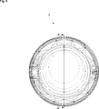
- Fig. 4 demonstrates a front view of the front door according to the present invention.
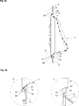
- Fig. 5a demonstrates a cross-sectional view of the front door taken along lines E-E of Fig. 4 while a glass bowl is aligned to fit in an inner lid recess and Fig. 5b demonstrates an enlarged view of detail X in Fig. 5a according to the present invention.
- Fig. 6 demonstrates a cross-sectional view of the front door taken along lines E-E of Fig. 4 while the glass bowl is fully fitted into the inner lid recess according to the present invention.
- Fig. 7a demonstrates a perspective view of the glass bowl with the inner lid and Fig. 7b demonstrates a cross-sectional view of the same taken along lines M-M of Fig. 7a according to the present invention.
- Fig. 8a demonstrates a cross-sectional view of the front door taken along lines E-E of Fig. 4 and Fig 8b demonstrates enlarged views of detail X and detail Y of Fig. 8a according to the present invention.
- Fig. 9a demonstrates a cross-sectional view of the front door taken along lines E-E of Fig. 4 while the outer lid is about to engage with the inner lid of the front door and Fig. 9b demonstrates an enlarged view of detail Y of Fig. 9a according to the present invention.
- Fig. 10a demonstrates a cross-sectional view of the front door taken along lines E-E of Fig. 4 when the outer lid is engaged with the inner lid of the front door and Fig. 10b demonstrates an enlarged view of detail Y of Fig. 10a according to the present invention.
- Fig. 11a demonstrates a cross-sectional view of the front door taken along lines E-E of Fig. 4 according to another embodiment of the present invention and Fig. 11b demonstrates an enlarged view of detail Y of Fig. 11a according to the present invention.
- the present invention relates to a laundry washing machine (1) with drying function, comprising a front door (2) allowing access into a drum.
- An electric motor conventionally rotates the drum, for instance by means of a pulley mechanism or a direct drive mechanism so that bidirectional rotation of the drum is effected during drying cycles.
- the front door (2) installed on the body front wall (4) of the laundry washing machine (1) comprises a front door cover (3) to which an outer lid (6) is attached and a glass bowl (7) is fitted between the outer lid (6) and an inner lid (5) positioned at the rear side of the front door (2) assembly.
- a leak-proof front door (2) assembly in the laundry washing machine (1) according to the invention is effective in ensuring leak-proof installation of the glass bowl (7) between the inner and outer lids (5, 6) of the machine’s front door (2).
- the glass bowl (7) is inserted into recesses within the inner lid (5) structure ensuring secure positioning of the glass bowl (7) between the inner and outer lids (5, 6) so that rotational movement of the drum does not affect locked position of the glass bowl (7) being sandwiched between the inner lid (5) and outer lid (6).
- the concave glass bowl (7) comprises a first connection extension (11) as a radial extension projecting annularly from part of the glass bowl rim (8).
- the first connection extension (11) is aligned with the open side of the inner lid recess (9) and is fitted into the inner lid recess (9) by way of rotating the glass bowl (7) so as to bring the first connection extension (11) into face to face alignment with the inner lid recess (9).
- the inner lid recess (9) is therefore structured to house the first connection extension (11) in a snug-fit manner.
- the inner lid recess (9) in the form of a U-shaped housing encloses the first connection extension (11) bidirectionally by a pair of opposite recess portions extending in parallel with the first connection extension (11) so as to receive and support the same thereinbetween.
- a first recess portion (19) of the inner lid recess (9) as one of the opposite parts of the U-shaped form is larger with a greater height with respect to the other oppositely situated second recess portion (20), providing additional support for carrying of the glass bowl (7) by the inner lid (5).
- the first recess portion (19) extends to a curvature region (21) leaning on the first connection extension’s (11) radially innermost portion.
- the curvature region (21) defines a tapered curved end part of the first recess portion (19), which supports the glass bowl (7) without establishing therewith a sharp contact edge, thereby avoiding damage to the same.
- the first recess portion (19) covering a larger portion of the first connection extension (11) surface compared to the second recess portion (20), is disposed on the inner side of the inner lid (5), thereby rigidly supporting the glass bowl (7) from its internal side surface.
- a second connection extension (12) of the glass bowl (7) positioned radially oppositely to the first connection extension (11) is juxtaposed with a contact surface (10) of the inner lid (5).
- the contact surface (10) extends through the inner lid (5) surface as an outwardly curved part leading to another portion of the curvature region (21) at the end thereof.
- the curvature region (21) again supports the glass bowl (7) from its internal side surface without having a sharp contact edge pressing on it.
- the fixation of the glass bowl (7) is ensured by the attachment of the outer lid (6) to the inner lid (5) being in engagement with the glass bowl (7).
- the outer lid (6) comprises a plurality of connection elements in its structure, whose shafts extend perpendicular to the front door’s (2) plane. Further, it establishes a latching connection with the inner lid (5) when it is mounted in a sliding manner by way of rotating the same a certain amount with respect to the inner lid (5), upon which the two parts are inter-locked so as to secure the glass bowl (7) and ensure alignment of the connection element holes on the inner lid (5) with the respective openings of the outer lid (6).
- the outer lid (6) having an insertion portion (13) ensures attachment of the outer lid (6) with the inner lid (5) while providing fixation of the glass bowl (7) thereinbetween.
- the insertion portion (13) connects with the inner lid (5) through a slide bar (14) extending outwardly in the form of a first section of a two-section structure, each subsequent section of the two-section structure extending linearly.
- the slide bar (14) mechanically connects with the inner lid (5) such that it engages with a receiving bar (15) thereof, providing a contact portion therewith.
- the contact portion extends along the second linear section of the two-section structure being juxtaposed with the receiving bar (15) forming the outer section of another two-section structure projecting from the inner lid (5) in the direction of the outer lid (6).
- a planar extension wall (17) of the inner lid (5) leads to a second section, namely the receiving bar (15) and the latter engages with the slide bar (14) so that the inner and outer lids (5, 6) are mutually inter-engaged to ensure maintenance of the installed position of the first connection extension (11) in the inner lid recess (9).
- the axes along which the first sections of the opposite lids extend are perpendicular to the front door’s (2) plane and the contact plane along which slide bar (14) and the receiving bar (15) are juxtaposed is preferably substantially perpendicular to the axis of the first section of the two-section structure of the outer lid (6) or the axis of the extension wall (17).
- the receiving bar (15) projects as a mirror image of the slide bar (14) of the outer lid (6) and receives the slide bar (14) into an inner cavity defined by the extension wall (17) together with the receiving bar (15).
- the slide bar (14) enters into the cavity of the preferably L-shaped or at least V-shaped structure of the receiving bar (15) with the extension wall (17), ensuring a more rigid contact surface and engagement relation between the inner and outer lids (5, 6).
- the accurate positioning of the outer lid (6) is accomplished according to an installment angle (22).
- the installment angle (22) is determined as the angle of the contact plane between the slide bar (14) and the receiving bar (15) with respect to the axis perpendicular to the front door’s (2) plane.
- a greater installment angle (22) value up to 90 degrees is more effective in compensating the dynamic forces exerted by the laundry on the inner surface of the glass bowl (7) due to the fact that the forces applied on the glass bowl (7) can be first transferred to the outer lid (6) and then to the inner lid (5) thanks to the efficiency of the inter-connecting structure between the two lids.
- the resting portions (16) retain the second connection extension (12) of the glass bowl (7) in connect with the contact surface (10) of the inner lid (5), forcing the second connection extension (12) against the contact surface (10).
- the present invention proposes a laundry washing machine (1) comprising a front door (2) allowing access into a drum, an electric motor rotating the drum and a leak-proofing front door (2) assembly effective in installation of a glass bowl (7) between an inner and outer lid (5, 6) of the laundry washing machine (1) front door (2).
- the glass bowl (7) comprises first and second connection extensions (11, 12) protruding radially from a glass bowl rim (8) portion, the first connection extension (11) being structured to fit into an inner lid recess (9) of the inner lid (5), the glass bowl (7) being fixated by attachment of the outer lid (6) to the inner lid (5) in engagement therewith such that the inner lid recess (9) is structured to house the first connection extension (11) in a snug-fit manner in the inter-locked position of the inner and outer lids (5, 6).
- the first connection extension (11) is aligned with open side of the inner lid recess (9) and is fitted into the inner lid recess (9) by way of rotating the glass bowl (7) so as to bring the first connection extension (11) into face to face alignment with the inner lid recess (9).
- the inner lid recess (9) is in the form of a U-shaped housing enclosing the first connection extension (11) bidirectionally by a pair of opposite recess portions extending in parallel with the first connection extension (11) so as to receive and support the same thereinbetween.
- a first recess portion (19) of the inner lid recess (9) forming one of the opposite linear extensions of the U-shaped form is larger with a greater height with respect to other oppositely situated second recess portion (20).
- the first recess portion (19) is disposed on the inner side of the inner lid (5), supporting the glass bowl (7) from its inner side.
- the second connection extension (12) of the glass bowl (7) disposed radially oppositely to the first connection extension (11) is juxtaposed with a contact surface (10) of the inner lid (5) and the outer lid (6) is slidably mountable such that the inner and outer lids (5, 6) are inter-locked with each other.
- the outer lid (6) comprises an insertion portion (13) connecting with the inner lid (5), the insertion portion (13) having a slide bar (14) extending in the direction of the inner lid (5) and mechanically connecting with a receiving bar (15) thereof, providing a contact portion and engagement relation between the inner and outer lids (5, 6).
- the insertion portion (13) of the outer lid (6) and the inner lid (5) comprise two-section structures, each subsequent section of the two two-section structures extending linearly.
- the receiving bar (15) forms the outer section of the two-section structure projecting from the inner lid (5) in the direction of the outer lid (6) and the slide bar (14) forms the outer section of the two-section structure projecting from the outer lid (6) in the direction of the inner lid (5).
- the receiving bar (15) engages with the slide bar (14) in a juxtaposed manner so as to create a contact plane along which the inner and outer lids (5, 6) are mutually inter-engaged.
- the axes along which the inner sections of the two-section structures of the opposite lids extend are perpendicular to the front door’s (2) plane and an installment angle (22) of the contact plane with respect to the axis perpendicular to the front door’s (2) plane and along which contact plane the slide bar (14) and the receiving bar (15) are juxtaposed is up to 90 degrees.
- an outer lid retainment portion (18) of the outer lid (6) radially on the opposite side of the insertion portion (13) provides additional support for the first connection extension (11) and the second recess portion (20) in direct contact therewith.
- the insertion portion (13) comprises resting portions (16) extending perpendicular to the front door’s (2) plane and supporting the glass bowl (7) from its outer side in direct contact therewith.
- the resting portions (16) retain the second connection extension (12) of the glass bowl (7) in connect with the contact surface (10) of the inner lid (5), forcing the second connection extension (12) against the contact surface (10).
- the inner lid (5) comprises an annular curvature region (21) in the form of a curved end part leaning on the glass bowl (7) whereby the latter is supported without establishing therewith a sharp contact surface.
- the present invention therefore proposes a leak-proof front door (2) assembly involving an easy and practical installation of the front door components as well as a decreased number of individual parts lowering manufacturing costs with a simplified mechanical structure.
Landscapes
- Engineering & Computer Science (AREA)
- Textile Engineering (AREA)
- Main Body Construction Of Washing Machines And Laundry Dryers (AREA)
Abstract
The present invention relates to a laundry washing machine (1) comprising a mechanically improved leak-proof system for the front door (2) glass bowl (7) of the machine so as to maintain mutual contact between the inner and outer door frames thereof. The present invention more particularly relates to a laundry washing machine (1) comprising a front door (2) allowing access into a drum, an electric motor rotating the drum and a leak-proof front door (2) assembly effective in installation of a glass bowl (7) between an inner and outer lid (5, 6) of the laundry washing machine (1) front door (2).
Description
The present invention relates to a laundry washing machine comprising a mechanically improved leak-proof system for the front door glass bowl of the machine so as to maintain mutual contact between the inner and outer door frames thereof.
A laundry washing machine comprises a generally six-sided cabinet with a front side door by which one can put in a laundry to be washed. A gasket in connect with the front access opening is connected to a tub opening and a drum opening, the drum being rotatably disposed inside the tub, can be accessed through the front access opening.
A laundry washing machine comprises a drum rotatable in the tub such that water and detergent held in a lower part of the tub is used to perform washing of the laundry whereby dirt and filth attached to the laundry is removed as a result of mechanical interaction of cloth items with each other and with the drum surfaces. Typically, an electric motor rotates the drum directly or by means of a driving pulley so that forward and reverse rotation of the drum is effected during the washing and/or drying cycles.
During the rotation of the drum, wet or moisture-laden laundry with considerable weight applies force on the glass bowl of the machine’s front door. The exerted force on the glass bowl varies depending on the weight of the laundry and leads to deformation on the relatively weaker plastic parts of the front door connection structures. In the event that the inter-connected structure retaining the front door glass bowl cannot compensate the dynamically changing unsteady forces resulting from the rotational movement of the drum, water leakage occurs from between the gasket and the glass bowl. Water leakage may typically influence customer impressions to the extent that it is basically associated with a low quality product item. Further, water leakage can also cause safety and hygiene concerns on the part of the customers.
The glass bowl is conventionally placed between the inner and outer lids of the front door. The glass bowl is fixated by way of connecting the inner lid with the outer lid by means of a plurality of connection elements establishing threaded connections. The glass bowl is conventionally positioned between the inner and outer lids in a sandwiched manner while the latter two are fixedly attached to each other. This configuration may result in that the connection elements get loose over time, thereby causing water leakage. The deformation of lid connections occur due to the low resilience of the peripheral connection components around the glass bowl against the dynamic force changes by the laundry inside the drum during the rotation thereof.
The present invention therefore proposes a leak-proof front door assembly in which the inner lid and outer lid of the front door typically provide a mutually leakage-free interference engagement with the glass bowl during the operation of the machine.
A prior art publication in the technical field of the present invention may be referred to as US2005262681 disclosing a door of a drum washer and an assembling method for the same, in which a structure of a door is improved to facilitate assembly of the door. The door of a drum washer includes an upper cover having a hollow, central portion downwardly tapered at a predetermined angle and a main boss formed at a predetermined length. The center cover is connected to a lower portion of the upper cover, having a connecting boss coupled to the main boss, and a lower cover connected to a lower portion of the center cover, having a connecting boss groove corresponding to the connecting boss. The assembling method includes connecting an upper cover provided with a main boss to a center cover provided with a connecting boss corresponding to the main boss, inserting a door glass bowl to a lower portion at an inner circumference of the upper cover, and connecting a lower cover provided with a connecting boss groove corresponding to the connecting boss of the center cover to a lower portion of the center cover.
The present invention, on the other hand, provides a glass bowl connection structure involving a leakage-free engagement relation with the inner and outer lid of the front door thereinbetween, thereby ensuring efficiency in preventing water leakage therethrough.
The present invention provides a front door assembly with a leak-proof glass bowl for a laundry washing machine, which is defined by the characterizing features in Claim 1 and subsequent Claims.
Primary object of the present invention is hence to provide an improved front door assembly with a leak-proof glass bowl for a laundry washing machine.
The present invention proposes a laundry washing machine with a glass bowl having a pair of connection extensions radially projecting from the outer annular rim of the glass bow. The first connection extension enters into an inner lid recess and the outer lid is then mounted to the inner lid to be engaged therewith in the manner that the inner lid recess receives the first connection extension in a snug-fit relation in the inter-locked position of the inner and outer lids.
When mounting the glass bowl, the first connection extension thereof is rotatably aligned to be fitted into the inner lid recess and is fitted into the inner lid recess having a U-shaped housing receiving the first connection extension in the manner to be supported by opposite recess portions in parallel.
One of the opposite linear extensions of the U-shaped form, the first recess portion, being disposed on the inner side of the inner lid, is larger with a greater height so as to support the glass bowl from its inner side.
The second connection extension is disposed diametrically opposite to the first connection extension and an insertion portion of the outer lid in engagement relation with the inner lid provides a contact portion between the inner and outer lids by which the glass bowl is forced against the inner lid.
The outer lid and the inner lid comprise two-section structures, having linear sections, the outer sections forming in engagement the contact portion in a juxtaposed manner.
Accompanying drawings are given solely for the purpose of exemplifying a laundry washing machine with a front door assembly with a leak-proof glass bowl between an inner lid and an outer lid, whose advantages over prior art were outlined above and will be explained in brief hereinafter.
The drawings are not meant to delimit the scope of protection as identified in the claims nor should they be referred to alone in an effort to interpret the scope identified in the claims without recourse to the technical disclosure in the description of the present invention.
Fig. 1 demonstrates a general perspective view of the laundry washing machine according to the present invention.
Fig. 2 demonstrates a front view of the laundry washing machine according to the present invention.
Fig 3 demonstrates a perspective view of the front door components in an unassembled manner according to the present invention.
Fig. 4 demonstrates a front view of the front door according to the present invention.
Fig. 5a demonstrates a cross-sectional view of the front door taken along lines E-E of Fig. 4 while a glass bowl is aligned to fit in an inner lid recess and Fig. 5b demonstrates an enlarged view of detail X in Fig. 5a according to the present invention.
Fig. 6 demonstrates a cross-sectional view of the front door taken along lines E-E of Fig. 4 while the glass bowl is fully fitted into the inner lid recess according to the present invention.
Fig. 7a demonstrates a perspective view of the glass bowl with the inner lid and Fig. 7b demonstrates a cross-sectional view of the same taken along lines M-M of Fig. 7a according to the present invention.
Fig. 8a demonstrates a cross-sectional view of the front door taken along lines E-E of Fig. 4 and Fig 8b demonstrates enlarged views of detail X and detail Y of Fig. 8a according to the present invention.
Fig. 9a demonstrates a cross-sectional view of the front door taken along lines E-E of Fig. 4 while the outer lid is about to engage with the inner lid of the front door and Fig. 9b demonstrates an enlarged view of detail Y of Fig. 9a according to the present invention.
Fig. 10a demonstrates a cross-sectional view of the front door taken along lines E-E of Fig. 4 when the outer lid is engaged with the inner lid of the front door and Fig. 10b demonstrates an enlarged view of detail Y of Fig. 10a according to the present invention.
Fig. 11a demonstrates a cross-sectional view of the front door taken along lines E-E of Fig. 4 according to another embodiment of the present invention and Fig. 11b demonstrates an enlarged view of detail Y of Fig. 11a according to the present invention.
The following numerals are assigned to different parts referred to in the detailed description of the present invention:
1) Laundry washing machine
2) Front door
3) Front door cover
4) Body front wall
5) Inner lid
6) Outer lid
7) Glass bowl
8) Glass bowl rim
9) Inner lid recess
10) Contact surface
11) First connection extension
12) Second connection extension
13) Insertion portion
14) Slide bar
15) Receiving bar
16) Resting portion
17) Extension wall
18) Outer lid retainment portion
19) First recess portion
20) Second recess portion
21) Curvature region
22) Installment angle
The present invention relates to a laundry washing machine (1) with drying function, comprising a front door (2) allowing access into a drum. An electric motor conventionally rotates the drum, for instance by means of a pulley mechanism or a direct drive mechanism so that bidirectional rotation of the drum is effected during drying cycles.
The front door (2) installed on the body front wall (4) of the laundry washing machine (1) comprises a front door cover (3) to which an outer lid (6) is attached and a glass bowl (7) is fitted between the outer lid (6) and an inner lid (5) positioned at the rear side of the front door (2) assembly.
A leak-proof front door (2) assembly in the laundry washing machine (1) according to the invention is effective in ensuring leak-proof installation of the glass bowl (7) between the inner and outer lids (5, 6) of the machine’s front door (2).
In the proposed system, the glass bowl (7) is inserted into recesses within the inner lid (5) structure ensuring secure positioning of the glass bowl (7) between the inner and outer lids (5, 6) so that rotational movement of the drum does not affect locked position of the glass bowl (7) being sandwiched between the inner lid (5) and outer lid (6).
The concave glass bowl (7) comprises a first connection extension (11) as a radial extension projecting annularly from part of the glass bowl rim (8). The first connection extension (11) is aligned with the open side of the inner lid recess (9) and is fitted into the inner lid recess (9) by way of rotating the glass bowl (7) so as to bring the first connection extension (11) into face to face alignment with the inner lid recess (9). The inner lid recess (9) is therefore structured to house the first connection extension (11) in a snug-fit manner.
The inner lid recess (9) in the form of a U-shaped housing encloses the first connection extension (11) bidirectionally by a pair of opposite recess portions extending in parallel with the first connection extension (11) so as to receive and support the same thereinbetween. A first recess portion (19) of the inner lid recess (9) as one of the opposite parts of the U-shaped form is larger with a greater height with respect to the other oppositely situated second recess portion (20), providing additional support for carrying of the glass bowl (7) by the inner lid (5). The first recess portion (19) extends to a curvature region (21) leaning on the first connection extension’s (11) radially innermost portion. The curvature region (21) defines a tapered curved end part of the first recess portion (19), which supports the glass bowl (7) without establishing therewith a sharp contact edge, thereby avoiding damage to the same. The first recess portion (19) covering a larger portion of the first connection extension (11) surface compared to the second recess portion (20), is disposed on the inner side of the inner lid (5), thereby rigidly supporting the glass bowl (7) from its internal side surface.
A second connection extension (12) of the glass bowl (7) positioned radially oppositely to the first connection extension (11) is juxtaposed with a contact surface (10) of the inner lid (5). The contact surface (10) extends through the inner lid (5) surface as an outwardly curved part leading to another portion of the curvature region (21) at the end thereof. The curvature region (21) again supports the glass bowl (7) from its internal side surface without having a sharp contact edge pressing on it.
The fixation of the glass bowl (7) is ensured by the attachment of the outer lid (6) to the inner lid (5) being in engagement with the glass bowl (7). The outer lid (6) comprises a plurality of connection elements in its structure, whose shafts extend perpendicular to the front door’s (2) plane. Further, it establishes a latching connection with the inner lid (5) when it is mounted in a sliding manner by way of rotating the same a certain amount with respect to the inner lid (5), upon which the two parts are inter-locked so as to secure the glass bowl (7) and ensure alignment of the connection element holes on the inner lid (5) with the respective openings of the outer lid (6).
The outer lid (6) having an insertion portion (13) ensures attachment of the outer lid (6) with the inner lid (5) while providing fixation of the glass bowl (7) thereinbetween. The insertion portion (13) connects with the inner lid (5) through a slide bar (14) extending outwardly in the form of a first section of a two-section structure, each subsequent section of the two-section structure extending linearly. The slide bar (14) mechanically connects with the inner lid (5) such that it engages with a receiving bar (15) thereof, providing a contact portion therewith. The contact portion extends along the second linear section of the two-section structure being juxtaposed with the receiving bar (15) forming the outer section of another two-section structure projecting from the inner lid (5) in the direction of the outer lid (6). In sum, a planar extension wall (17) of the inner lid (5) leads to a second section, namely the receiving bar (15) and the latter engages with the slide bar (14) so that the inner and outer lids (5, 6) are mutually inter-engaged to ensure maintenance of the installed position of the first connection extension (11) in the inner lid recess (9). The axes along which the first sections of the opposite lids extend are perpendicular to the front door’s (2) plane and the contact plane along which slide bar (14) and the receiving bar (15) are juxtaposed is preferably substantially perpendicular to the axis of the first section of the two-section structure of the outer lid (6) or the axis of the extension wall (17).
The receiving bar (15) projects as a mirror image of the slide bar (14) of the outer lid (6) and receives the slide bar (14) into an inner cavity defined by the extension wall (17) together with the receiving bar (15). In sum, the slide bar (14) enters into the cavity of the preferably L-shaped or at least V-shaped structure of the receiving bar (15) with the extension wall (17), ensuring a more rigid contact surface and engagement relation between the inner and outer lids (5, 6).
The accurate positioning of the outer lid (6) is accomplished according to an installment angle (22). The installment angle (22) is determined as the angle of the contact plane between the slide bar (14) and the receiving bar (15) with respect to the axis perpendicular to the front door’s (2) plane. A greater installment angle (22) value up to 90 degrees is more effective in compensating the dynamic forces exerted by the laundry on the inner surface of the glass bowl (7) due to the fact that the forces applied on the glass bowl (7) can be first transferred to the outer lid (6) and then to the inner lid (5) thanks to the efficiency of the inter-connecting structure between the two lids. The forces exerted on the glass bowl (7) are directly transferred to the outer lid (6) through the resting portions (16) thereof and then the receiving bar (15) in engagement with the insertion portion (13) retains the same in position and hence the outer lid in its locked position. In brief, the engagement structure between the inner and outer lids (5, 6) prevents the glass bowl (7) from forcing the outer lid (6) outwardly to create an in-between opening, which causes leakage. Further, an outer lid retainment portion (18) radially on the opposite side of the insertion portion (13) also having resting portions (16) provides an additional external support for the first connection extension (11) in direct contact therewith, as well as for the second recess portion (20) also in direct connection with the same.
The insertion portion’s (13) resting portions (16), positioned proximate the slide bar (14) extending in parallel with the extension wall (17), support the glass bowl (7). The resting portions (16) retain the second connection extension (12) of the glass bowl (7) in connect with the contact surface (10) of the inner lid (5), forcing the second connection extension (12) against the contact surface (10).
In summary, the present invention proposes a laundry washing machine (1) comprising a front door (2) allowing access into a drum, an electric motor rotating the drum and a leak-proofing front door (2) assembly effective in installation of a glass bowl (7) between an inner and outer lid (5, 6) of the laundry washing machine (1) front door (2).
In one embodiment of the present invention, the glass bowl (7) comprises first and second connection extensions (11, 12) protruding radially from a glass bowl rim (8) portion, the first connection extension (11) being structured to fit into an inner lid recess (9) of the inner lid (5), the glass bowl (7) being fixated by attachment of the outer lid (6) to the inner lid (5) in engagement therewith such that the inner lid recess (9) is structured to house the first connection extension (11) in a snug-fit manner in the inter-locked position of the inner and outer lids (5, 6).
In a further embodiment of the present invention, the first connection extension (11) is aligned with open side of the inner lid recess (9) and is fitted into the inner lid recess (9) by way of rotating the glass bowl (7) so as to bring the first connection extension (11) into face to face alignment with the inner lid recess (9).
In a further embodiment of the present invention, the inner lid recess (9) is in the form of a U-shaped housing enclosing the first connection extension (11) bidirectionally by a pair of opposite recess portions extending in parallel with the first connection extension (11) so as to receive and support the same thereinbetween.
In a further embodiment of the present invention, a first recess portion (19) of the inner lid recess (9) forming one of the opposite linear extensions of the U-shaped form is larger with a greater height with respect to other oppositely situated second recess portion (20).
In a further embodiment of the present invention, the first recess portion (19) is disposed on the inner side of the inner lid (5), supporting the glass bowl (7) from its inner side.
In a further embodiment of the present invention, the second connection extension (12) of the glass bowl (7) disposed radially oppositely to the first connection extension (11) is juxtaposed with a contact surface (10) of the inner lid (5) and the outer lid (6) is slidably mountable such that the inner and outer lids (5, 6) are inter-locked with each other.
In a further embodiment of the present invention, the outer lid (6) comprises an insertion portion (13) connecting with the inner lid (5), the insertion portion (13) having a slide bar (14) extending in the direction of the inner lid (5) and mechanically connecting with a receiving bar (15) thereof, providing a contact portion and engagement relation between the inner and outer lids (5, 6).
In a further embodiment of the present invention, the insertion portion (13) of the outer lid (6) and the inner lid (5) comprise two-section structures, each subsequent section of the two two-section structures extending linearly.
In a further embodiment of the present invention, the receiving bar (15) forms the outer section of the two-section structure projecting from the inner lid (5) in the direction of the outer lid (6) and the slide bar (14) forms the outer section of the two-section structure projecting from the outer lid (6) in the direction of the inner lid (5).
In a further embodiment of the present invention, the receiving bar (15) engages with the slide bar (14) in a juxtaposed manner so as to create a contact plane along which the inner and outer lids (5, 6) are mutually inter-engaged.
In a further embodiment of the present invention, the axes along which the inner sections of the two-section structures of the opposite lids extend are perpendicular to the front door’s (2) plane and an installment angle (22) of the contact plane with respect to the axis perpendicular to the front door’s (2) plane and along which contact plane the slide bar (14) and the receiving bar (15) are juxtaposed is up to 90 degrees.
In a further embodiment of the present invention, an outer lid retainment portion (18) of the outer lid (6) radially on the opposite side of the insertion portion (13) provides additional support for the first connection extension (11) and the second recess portion (20) in direct contact therewith.
In a further embodiment of the present invention, the insertion portion (13) comprises resting portions (16) extending perpendicular to the front door’s (2) plane and supporting the glass bowl (7) from its outer side in direct contact therewith.
In a further embodiment of the present invention, the resting portions (16) retain the second connection extension (12) of the glass bowl (7) in connect with the contact surface (10) of the inner lid (5), forcing the second connection extension (12) against the contact surface (10).
In a further embodiment of the present invention, the inner lid (5) comprises an annular curvature region (21) in the form of a curved end part leaning on the glass bowl (7) whereby the latter is supported without establishing therewith a sharp contact surface.
The present invention therefore proposes a leak-proof front door (2) assembly involving an easy and practical installation of the front door components as well as a decreased number of individual parts lowering manufacturing costs with a simplified mechanical structure.
Claims (15)
- A laundry washing machine (1) comprising a front door (2) allowing access into a drum, an electric motor rotating the drum and a leak-proof front door (2) assembly effective in installation of a glass bowl (7) between an inner and outer lid (5, 6) of the laundry washing machine (1) front door (2), characterized in thatthe glass bowl (7) comprises first and second connection extensions (11, 12) protruding radially from a glass bowl rim (8) portion, the first connection extension (11) being structured to fit into an inner lid recess (9) of the inner lid (5), the glass bowl (7) being fixated by attachment of the outer lid (6) to the inner lid (5) in engagement therewith such that the inner lid recess (9) is structured to house the first connection extension (11) in a snug-fit manner in the inter-locked position of the inner and outer lids (5, 6).
- A laundry washing machine (1) as in Claim 1, characterized in that the first connection extension (11) is aligned with open side of the inner lid recess (9) and is fitted into the inner lid recess (9) by way of rotating the glass bowl (7) so as to bring the first connection extension (11) into face to face alignment with the inner lid recess (9).
- A laundry washing machine (1) as in Claim 2, characterized in that the inner lid recess (9) is in the form of a U-shaped housing enclosing the first connection extension (11) bidirectionally by a pair of opposite recess portions extending in parallel with the first connection extension (11) so as to receive and support the same thereinbetween.
- A laundry washing machine (1) as in Claim 3, characterized in that a first recess portion (19) of the inner lid recess (9) forming one of the opposite linear extensions of the U-shaped form is larger with a greater height with respect to other oppositely situated second recess portion (20).
- A laundry washing machine (1) as in Claim 4, characterized in that the first recess portion (19) is disposed on the inner side of the inner lid (5), supporting the glass bowl (7) from its inner side.
- A laundry washing machine (1) as in any one of the above claims, characterized in that the second connection extension (12) of the glass bowl (7) disposed radially oppositely to the first connection extension (11) is juxtaposed with a contact surface (10) of the inner lid (5) and the outer lid (6) is slidably mountable such that the inner and outer lids (5, 6) are inter-locked with each other.
- A laundry washing machine (1) as in Claim 6, characterized in that the outer lid (6) comprises an insertion portion (13) connecting with the inner lid (5), the insertion portion (13) having a slide bar (14) extending in the direction of the inner lid (5) and mechanically connecting with a receiving bar (15) thereof, providing a contact portion and engagement relation between the inner and outer lids (5, 6).
- A laundry washing machine (1) as in Claim 7, characterized in that the insertion portion (13) of the outer lid (6) and the inner lid (5) comprise two-section structures, each subsequent section of the two two-section structures extending linearly.
- A laundry washing machine (1) as in Claim 8, characterized in that the receiving bar (15) forms the outer section of the two-section structure projecting from the inner lid (5) in the direction of the outer lid (6) and the slide bar (14) forms the outer section of the two-section structure projecting from the outer lid (6) in the direction of the inner lid (5).
- A laundry washing machine (1) as in Claim 9, characterized in that the receiving bar (15) engages with the slide bar (14) in a juxtaposed manner so as to create a contact plane along which the inner and outer lids (5, 6) are mutually inter-engaged.
- A laundry washing machine (1) as in Claim 10, characterized in that the axes along which the inner sections of the two-section structures of the opposite lids extend are perpendicular to the front door’s (2) plane and an installment angle (22) of the contact plane with respect to the axis perpendicular to the front door’s (2) plane and along which contact plane the slide bar (14) and the receiving bar (15) are juxtaposed is up to 90 degrees.
- A laundry washing machine (1) as in Claim 4 or 7, characterized in that an outer lid retainment portion (18) of the outer lid (6) radially on the opposite side of the insertion portion (13) provides additional support for the first connection extension (11) and the second recess portion (20) in direct contact therewith.
- A laundry washing machine (1) as in Claim 7, characterized in that the insertion portion (13) comprises resting portions (16) extending perpendicular to the front door’s (2) plane and supporting the glass bowl (7) from its outer side in direct contact therewith.
- A laundry washing machine (1) as in Claim 13, characterized in that the resting portions (16) retain the second connection extension (12) of the glass bowl (7) in connect with the contact surface (10) of the inner lid (5), forcing the second connection extension (12) against the contact surface (10).
- A laundry washing machine (1) as in Claim 1, characterized in that the inner lid (5) comprises an annular curvature region (21) in the form of a curved end part leaning on the glass bowl (7) whereby the latter is supported without establishing therewith a sharp contact surface.
Priority Applications (2)
| Application Number | Priority Date | Filing Date | Title |
|---|---|---|---|
| PCT/EP2015/056976 WO2016155785A1 (en) | 2015-03-31 | 2015-03-31 | Laundry washing machine having an improved leak-proof door assembly |
| TR2016/03863A TR201603863A2 (en) | 2015-03-31 | 2016-03-25 | WASHING MACHINE WITH IMPROVED SEALING DOOR SYSTEM |
Applications Claiming Priority (1)
| Application Number | Priority Date | Filing Date | Title |
|---|---|---|---|
| PCT/EP2015/056976 WO2016155785A1 (en) | 2015-03-31 | 2015-03-31 | Laundry washing machine having an improved leak-proof door assembly |
Publications (1)
| Publication Number | Publication Date |
|---|---|
| WO2016155785A1 true WO2016155785A1 (en) | 2016-10-06 |
Family
ID=52774246
Family Applications (1)
| Application Number | Title | Priority Date | Filing Date |
|---|---|---|---|
| PCT/EP2015/056976 Ceased WO2016155785A1 (en) | 2015-03-31 | 2015-03-31 | Laundry washing machine having an improved leak-proof door assembly |
Country Status (2)
| Country | Link |
|---|---|
| TR (1) | TR201603863A2 (en) |
| WO (1) | WO2016155785A1 (en) |
Cited By (2)
| Publication number | Priority date | Publication date | Assignee | Title |
|---|---|---|---|---|
| WO2019129423A1 (en) * | 2017-12-25 | 2019-07-04 | Arcelik Anonim Sirketi | A door for a washer/dryer |
| CN114808347A (en) * | 2021-01-18 | 2022-07-29 | 青岛海尔滚筒洗衣机有限公司 | Roller clothes treatment device |
Citations (4)
| Publication number | Priority date | Publication date | Assignee | Title |
|---|---|---|---|---|
| GB2118580A (en) * | 1982-04-16 | 1983-11-02 | Faini Spa | Window for washing machines |
| EP0293984A1 (en) * | 1987-06-02 | 1988-12-07 | Whirlpool International B.V. | Door for washing machines and the like, with an interchangeable bezel and means for ensuring door tightness when the bezel is absent |
| US20050262681A1 (en) | 2004-06-01 | 2005-12-01 | Lg Electronics Inc. | Door of drum washer and assembling method for the same |
| EP2740833A1 (en) * | 2012-12-06 | 2014-06-11 | Electrolux Home Products Corporation N.V. | Laundry treatment device with door assembly |
-
2015
- 2015-03-31 WO PCT/EP2015/056976 patent/WO2016155785A1/en not_active Ceased
-
2016
- 2016-03-25 TR TR2016/03863A patent/TR201603863A2/en unknown
Patent Citations (4)
| Publication number | Priority date | Publication date | Assignee | Title |
|---|---|---|---|---|
| GB2118580A (en) * | 1982-04-16 | 1983-11-02 | Faini Spa | Window for washing machines |
| EP0293984A1 (en) * | 1987-06-02 | 1988-12-07 | Whirlpool International B.V. | Door for washing machines and the like, with an interchangeable bezel and means for ensuring door tightness when the bezel is absent |
| US20050262681A1 (en) | 2004-06-01 | 2005-12-01 | Lg Electronics Inc. | Door of drum washer and assembling method for the same |
| EP2740833A1 (en) * | 2012-12-06 | 2014-06-11 | Electrolux Home Products Corporation N.V. | Laundry treatment device with door assembly |
Cited By (2)
| Publication number | Priority date | Publication date | Assignee | Title |
|---|---|---|---|---|
| WO2019129423A1 (en) * | 2017-12-25 | 2019-07-04 | Arcelik Anonim Sirketi | A door for a washer/dryer |
| CN114808347A (en) * | 2021-01-18 | 2022-07-29 | 青岛海尔滚筒洗衣机有限公司 | Roller clothes treatment device |
Also Published As
| Publication number | Publication date |
|---|---|
| TR201603863A2 (en) | 2016-10-21 |
Similar Documents
| Publication | Publication Date | Title |
|---|---|---|
| EP3181750B1 (en) | Laundry treatment device with door assembly | |
| KR102627713B1 (en) | Washing Machine | |
| EP3854931B1 (en) | A clothes treating system | |
| KR101278159B1 (en) | Drum type washer and Door of the same | |
| US8151603B2 (en) | Door for washing machine | |
| EP2435612B1 (en) | Laundry machine | |
| EP2161364A2 (en) | Drum-type washing machine | |
| KR102165604B1 (en) | Washing machine | |
| KR101890260B1 (en) | Washing Machine | |
| KR20110013170A (en) | Laundry treatment equipment | |
| US10988884B2 (en) | Clothes treating apparatus | |
| WO2016155785A1 (en) | Laundry washing machine having an improved leak-proof door assembly | |
| KR100445654B1 (en) | A lifter's installing structure of the drum type washer | |
| US10704177B2 (en) | Washing machine lid attachment | |
| CN110872779B (en) | Clothes processing equipment | |
| KR102882226B1 (en) | Washing machine | |
| JP4211979B2 (en) | Drum washing machine | |
| KR102254855B1 (en) | Apparatus for treating laundry | |
| WO2005118938A1 (en) | Assembly structure of a washing machine's console, and assembly method | |
| WO2016034225A1 (en) | Laundry washing and/or drying machine control panel housing fixation system | |
| CN109112798A (en) | A kind of drum-type washing machine observation window and roller washing machine | |
| CN107385763B (en) | Washing machine | |
| KR100445653B1 (en) | Balance-weight's mounting of a drum-washer | |
| KR102568674B1 (en) | Laundry treating apparatus | |
| CN217678191U (en) | Device for introduction into a liquid distribution system of a top-fed washing machine |
Legal Events
| Date | Code | Title | Description |
|---|---|---|---|
| 121 | Ep: the epo has been informed by wipo that ep was designated in this application |
Ref document number: 15712933 Country of ref document: EP Kind code of ref document: A1 |
|
| NENP | Non-entry into the national phase |
Ref country code: DE |
|
| 122 | Ep: pct application non-entry in european phase |
Ref document number: 15712933 Country of ref document: EP Kind code of ref document: A1 |