WO2016152680A1 - 太陽電池モジュール用取付具及び太陽電池モジュールの取付方法 - Google Patents
太陽電池モジュール用取付具及び太陽電池モジュールの取付方法 Download PDFInfo
- Publication number
- WO2016152680A1 WO2016152680A1 PCT/JP2016/058346 JP2016058346W WO2016152680A1 WO 2016152680 A1 WO2016152680 A1 WO 2016152680A1 JP 2016058346 W JP2016058346 W JP 2016058346W WO 2016152680 A1 WO2016152680 A1 WO 2016152680A1
- Authority
- WO
- WIPO (PCT)
- Prior art keywords
- solar cell
- cell module
- rail
- fixed
- fixing
- Prior art date
- Legal status (The legal status is an assumption and is not a legal conclusion. Google has not performed a legal analysis and makes no representation as to the accuracy of the status listed.)
- Ceased
Links
Images












Classifications
-
- H—ELECTRICITY
- H02—GENERATION; CONVERSION OR DISTRIBUTION OF ELECTRIC POWER
- H02S—GENERATION OF ELECTRIC POWER BY CONVERSION OF INFRARED RADIATION, VISIBLE LIGHT OR ULTRAVIOLET LIGHT, e.g. USING PHOTOVOLTAIC [PV] MODULES
- H02S20/00—Supporting structures for PV modules
- H02S20/20—Supporting structures directly fixed to an immovable object
- H02S20/22—Supporting structures directly fixed to an immovable object specially adapted for buildings
- H02S20/23—Supporting structures directly fixed to an immovable object specially adapted for buildings specially adapted for roof structures
-
- H—ELECTRICITY
- H02—GENERATION; CONVERSION OR DISTRIBUTION OF ELECTRIC POWER
- H02S—GENERATION OF ELECTRIC POWER BY CONVERSION OF INFRARED RADIATION, VISIBLE LIGHT OR ULTRAVIOLET LIGHT, e.g. USING PHOTOVOLTAIC [PV] MODULES
- H02S20/00—Supporting structures for PV modules
- H02S20/20—Supporting structures directly fixed to an immovable object
- H02S20/22—Supporting structures directly fixed to an immovable object specially adapted for buildings
- H02S20/23—Supporting structures directly fixed to an immovable object specially adapted for buildings specially adapted for roof structures
- H02S20/24—Supporting structures directly fixed to an immovable object specially adapted for buildings specially adapted for roof structures specially adapted for flat roofs
-
- H—ELECTRICITY
- H02—GENERATION; CONVERSION OR DISTRIBUTION OF ELECTRIC POWER
- H02S—GENERATION OF ELECTRIC POWER BY CONVERSION OF INFRARED RADIATION, VISIBLE LIGHT OR ULTRAVIOLET LIGHT, e.g. USING PHOTOVOLTAIC [PV] MODULES
- H02S30/00—Structural details of PV modules other than those related to light conversion
-
- Y—GENERAL TAGGING OF NEW TECHNOLOGICAL DEVELOPMENTS; GENERAL TAGGING OF CROSS-SECTIONAL TECHNOLOGIES SPANNING OVER SEVERAL SECTIONS OF THE IPC; TECHNICAL SUBJECTS COVERED BY FORMER USPC CROSS-REFERENCE ART COLLECTIONS [XRACs] AND DIGESTS
- Y02—TECHNOLOGIES OR APPLICATIONS FOR MITIGATION OR ADAPTATION AGAINST CLIMATE CHANGE
- Y02B—CLIMATE CHANGE MITIGATION TECHNOLOGIES RELATED TO BUILDINGS, e.g. HOUSING, HOUSE APPLIANCES OR RELATED END-USER APPLICATIONS
- Y02B10/00—Integration of renewable energy sources in buildings
- Y02B10/10—Photovoltaic [PV]
-
- Y—GENERAL TAGGING OF NEW TECHNOLOGICAL DEVELOPMENTS; GENERAL TAGGING OF CROSS-SECTIONAL TECHNOLOGIES SPANNING OVER SEVERAL SECTIONS OF THE IPC; TECHNICAL SUBJECTS COVERED BY FORMER USPC CROSS-REFERENCE ART COLLECTIONS [XRACs] AND DIGESTS
- Y02—TECHNOLOGIES OR APPLICATIONS FOR MITIGATION OR ADAPTATION AGAINST CLIMATE CHANGE
- Y02E—REDUCTION OF GREENHOUSE GAS [GHG] EMISSIONS, RELATED TO ENERGY GENERATION, TRANSMISSION OR DISTRIBUTION
- Y02E10/00—Energy generation through renewable energy sources
- Y02E10/50—Photovoltaic [PV] energy
Definitions
- the present invention relates to a solar cell module fixture used when installing a solar cell module, and relates to a solar cell module mounting method using such a solar cell module fixture.
- a solar cell module is fixed via an attachment such as a base or a metal fitting. That is, the fixture is fixed to an attachment object such as a column in which the roof surface and the lower end of the building are embedded in the ground, and the solar cell module is fixed on the attachment object via the attachment.
- a plurality of rail mounts are arranged in parallel at predetermined intervals on the roof surface of a flat roof building, and the sun The battery module is fixed.
- the long rail-like mounts are arranged in parallel at equal intervals, and the solar cell modules are arranged so as to straddle two adjacent rail-like mounts. That is, a portion near one side of the two opposing sides of the solar cell module is fixed to one rail-shaped gantry, and a portion near the other side is fixed to the other of the other rail-shaped gantry.
- a first module fixing portion for fixing the edge portion of the solar cell module at a relatively high position and a first module fixing portion for fixing the edge portion of the solar cell module at a relatively low position are mounted on each rail-like frame.
- Two module fixing portions are provided. And the part of one side vicinity of the two sides which a solar cell module opposes is fixed to the 1st module fixing
- the long rail-shaped gantry extends from one side of the two sides facing each other in plan view of the land roof to the other side. .
- a long rail-like pedestal extends over substantially the entire area between two sides facing each other in plan view.
- the some solar cell module is being fixed in the state where it paralleled without the gap along the longitudinal direction of the rail-shaped mount. That is, the parallel direction of the solar cell modules fixed to two adjacent rail-shaped mounts is the same as the longitudinal direction of the two rail-shaped mounts, and the other end to the other in the longitudinal direction of the two rail-shaped mounts A plurality of solar cell modules are spread all the way to the end. As a result, the solar cell modules are spread in a matrix over substantially the entire surface of the flat roof.
- the rail-shaped mount is attached to the roof surface by tightening the fixing nut after overlapping the mounting holes of the rail-shaped mount on the anchor bolts mounted on the roof surface. It is fixed to. And the attachment hole of the rail-shaped mount fixed to the roof surface and the attachment hole of the solar cell module are overlapped, and the solar cell module is fixed to the rail-shaped mount.
- Patent Document 1 has room for improvement from the viewpoint of further simplifying the work of mounting the solar cell module on the roof and the work of removing the rail-shaped member from the roof.
- an object of the present invention is to provide a solar cell module mounting tool and a solar cell module mounting method capable of simplifying the mounting work and the detaching work.
- One aspect of the present invention for solving the above problems is a solar cell module fixture for attaching a solar cell module to an object, the rail member fixed to the object, and the rail member A separate piece that is fixed to the solar cell module integrally, and the rail member includes a rail-side engaging portion, and the fixed piece includes a fixed-piece-side engaging portion.
- the rail-side engaging portion and the fixed piece-side engaging portion engage with each other so that the rail member and the fixed piece can be engaged, and the fixed piece is integrally fixed to the solar cell module.
- the solar cell module mounting tool is capable of sliding along the rail member while being engaged with the rail member.
- the solar cell module fixture of this aspect has a rail member that is fixed to an object to be attached to the solar cell module and a fixing piece that is fixed to the solar cell module as separate bodies, and the fixing work of the fixing piece to the solar cell module is wide.
- a fixed piece is fixed to a solar cell module in a place where a large work space can be secured, the integrated solar cell module and the fixed piece are transported on the roof, and the fixed piece and the rail member are engaged on the roof. It is possible to perform such mounting work.
- the integrated solar cell module and the fixing piece can be lowered from the roof, transported to a place where a large work space can be secured, and the removal operation can be performed. That is, the work of removing the screw and removing the fixing piece from the solar cell module can be performed in a wide place, and the removal work can be simplified.
- the slide piece can be moved along the rail member in a state where the fixed piece integrally fixed to the solar cell module is engaged with the rail member.
- the rail member includes a movement restricting portion that restricts the sliding movement of the fixed piece.
- the sliding movement of the fixed piece to an undesired position can be prevented. For this reason, it is possible to prevent a situation in which the engagement between the fixed piece and the rail member is erroneously released due to an unexpected force applied, and the solar cell module falls off the rail member together with the fixed piece. In other words, there is no need to re-engage the fixed piece and the rail member that have been accidentally released during the mounting operation of the solar cell module, thereby simplifying the mounting operation of the solar cell module. Can be achieved.
- the rail member includes a rail main body and a movement restricting member separate from the rail main body, and the movement restricting member is attached to the rail main body, and the movement restricting portion is attached to the rail member.
- the movement restricting member is attached near the end of the rail body.
- the rail member and the movement restricting member are separated from each other, and the movement restricting member is attached to the rail main body so that the movement restricting portion is formed on the rail member.
- this movement control member is attached to the edge part vicinity of a rail main body, and the movement control part is formed in the edge part vicinity of a rail member.
- a movement control part is formed after installing a solar cell module, a movement control part is formed, and it can prevent the drop-off
- the fixed piece is engaged with the rail member in a state of being positioned above the rail member, and includes a rail adjustment window portion, and the rail adjustment window portion includes the fixed piece. It is preferable to expose a portion of the rail member that overlaps the fixed piece when viewed from above.
- the state of the portion overlapping the fixed piece of the rail member can be confirmed without removing the fixed solar cell module and the fixed piece from the rail member, or moving the fixed piece.
- Work such as screwing can be performed on the portion of the member that overlaps the fixed piece.
- the nut or the like is not correctly tightened, it is possible to perform an operation of tightening the nut as it is. That is, since the work relating to the attachment can be performed without removing the fixed piece from the rail member or moving the fixed piece, the attachment work can be simplified.
- the fixed piece includes a flat bottom plate portion and two side wall portions respectively formed on one side and the other side of two opposite sides of the bottom plate portion, and the rail adjustment window portion is And a through-hole penetrating the bottom plate portion, and located between the two side wall portions.
- the fixed piece includes a flat bottom plate portion, and a plurality of engagement protrusions constituting the fixed piece side engaging portion are provided on the back surface side of the bottom plate portion,
- the engagement protrusion includes a first engagement protrusion and a second engagement protrusion that are arranged in parallel at a predetermined interval, and the first engagement protrusion and the second engagement protrusion are And a bent plate portion formed by bending a lower end side of the upright plate-like portion and a bent plate portion formed by bending a lower end side of the upright plate-like portion. It is preferable that the plate part and the bent plate part of the second engagement protrusion are each bent so as to protrude in a direction approaching each other.
- the fixed piece includes a flat bottom plate portion, and a plurality of engagement protrusions constituting the fixed piece side engaging portion are provided on a back surface side of the bottom plate portion.
- the mating projection has a standing plate portion and a curved plate portion continuous with the lower end of the standing plate portion, and has an elastically deformable portion, and the two engaging projections are arranged in parallel at a predetermined interval.
- the two standing plates are arranged so that their inner surfaces face each other, and the two curved plates are curved so as to swell outward.
- the movement restricting member has at least a top surface portion that covers the upper surface of the end portion of the rail body.
- the movement restricting member includes a flat plate-shaped top surface portion, two side surface forming portions extending downward from the top surface portion, and a front plate portion, and inside the movement restricting member, A storage space that is a space surrounded by the top surface portion, the two side surface forming portions, and the front plate portion is formed, and the storage space can store an end portion of the rail body.
- the movement restricting member is integrally fixed to the rail body via a fastening element that penetrates both the top surface portion and the rail body in a stacked state.
- Another aspect of the present invention is a solar cell module mounting method for mounting a plurality of solar power modules adjacent to each other using the solar cell module mounting tool described above, wherein the target Fixing the rail member to the solar cell module, fixing the fixed piece to the solar cell module, engaging the fixed piece fixed to the solar cell module with the rail member, and the solar cell module and the solar cell module Performing a step of sliding and moving a fixed piece, and a step of fixing a part of the solar cell module to the fixed piece fixed to another solar cell module disposed in an adjacent position. It is the attachment method of the solar cell module characterized.
- the step of fixing the fixing piece to the solar cell module can be performed in a place where a large work space can be secured. Furthermore, as described above, in the step of sliding the solar cell module and the fixed piece, fine adjustment in the alignment of the solar cell module can be performed while the fixed piece is engaged with the rail member. From these things, the attachment operation
- work of a solar cell module can be simplified. Moreover, adjacent solar cell modules are connected by performing a process of fixing a part of the solar cell modules to a fixing piece fixed to another solar cell module arranged at an adjacent position. As a result, it is possible to mount firmly and strong against external forces such as wind. Furthermore, in this step, the solar cell module and the fixed piece fixed to the other solar cell module are in a state in which they can slide relative to each other, and the alignment operation can be easily performed. From this, it is possible to perform firm attachment with a simple attachment operation.
- the fixing piece is fixed only to one side of two sides opposed in the inclination direction of the solar cell module.
- Another preferred aspect is a method for attaching a solar cell module to the object in a state where a plurality of solar power modules are adjacent to each other using the above-described solar cell module fixture, A step of fixing the rail member; a step of fixing the fixing piece to the solar cell module; and an engagement of the fixing piece fixed to the solar cell module with the rail member, the solar cell module and the fixing A step of sliding the piece and a step of fixing a part of the solar cell module to the fixed piece fixed to the other solar cell module arranged at an adjacent position.
- the movement restricting portion Prior to the step of sliding the solar cell module and the fixed piece, the movement restricting portion is provided at one end of the rail body. And a step of fixing the movement restricting member to the other end of the rail body after the step of sliding the solar cell module and the fixing piece. It is the attachment method of a solar cell module.
- the work related to the installation and removal of the solar cell module can be simplified.
- FIG. 1 It is a perspective view which shows a mode that the solar cell module was attached on the roof with the fixture for solar cell modules concerning embodiment of this invention. It is a perspective view which shows the solar cell module of FIG. It is a perspective view which shows the rail member of FIG. It is a disassembled perspective view which shows the rail member of FIG. It is a top view which shows the rail main body of FIG. It is a perspective view which shows the fixing piece of FIG. It is a perspective view which shows a mode that the fixed piece of FIG. 6 was seen from another direction. It is a perspective view which shows a mode that the fixed piece of FIG. 6 was seen from the back surface side. It is a side view which shows the fixing piece of FIG.
- FIG. 11 is a cross-sectional view illustrating a state where the rail body is fixed on the roof following FIG. 10. It is a perspective view which shows a mode that a fixing piece is fixed to a solar cell module following FIG. 11, and permeate
- FIG. 14 is an explanatory diagram schematically showing a state in which the solar cell module temporarily installed first is moved to the installation position, and then the solar cell module temporarily installed second is moved to the installation position, following FIG. a) shows a state of moving, and (b) shows a state of moving to the installation position.
- FIG. 16 is an explanatory diagram showing a state in which a part of the solar cell module temporarily installed first is fixed to a fixing piece fixed to the second temporarily installed solar cell module following FIG. 15. It is explanatory drawing which shows a mode that the solar cell module of the 2nd row is temporarily installed after attaching the solar cell module which comprises the row
- FIG. 22 is an explanatory view showing a state in which the fixed piece of FIG. 20 is engaged with the rail member of FIG. 21, and is engaged in the order of (a) to (c).
- the solar cell module 1 mounting structure of the present embodiment is a structure in which the solar cell module 1 is mounted on the roof 3 (target object) of the building via the solar cell module mounting tool 2. is there.
- the solar cell module fixture 2 includes a rail member 4 that is fixed on the roof 3 and a fixing piece 5 that is fixed to the solar cell module 1.
- the solar cell module 1 includes the fixing piece 5. It is in the state attached to the rail member 4 via.
- the roof 3 of this embodiment is a flat roof (flat roof), and has the flat roof surface 3a without an inclination.
- the solar cell module 1 is formed by attaching a frame 11 to the peripheral portion of the solar cell panel 10 as shown in FIG.
- the solar battery panel 10 is a substantially rectangular flat plate-like member, and is formed by sealing a solar battery cell provided with a photoelectric conversion element between a resin back surface sealing material and a glass substrate forming a light receiving surface. It is a plate-shaped member.
- the frame 11 includes a short-side member 12 attached so as to cover the short side of the solar cell panel 10 and a long-side member 13 attached so as to cover the long side.
- An annular frame 11 is formed.
- a flat plate-like fixed plate portion 15 protruding outward is formed.
- the fixed plate portion 15 is a portion protruding in a direction orthogonal to the thickness direction of the solar cell module 1 and is a plate-like portion whose shape in plan view is a substantially rectangular shape.
- the fixed plate portion 15 extends along the short side of the solar cell module 1, and the thickness direction thereof is the same as the thickness direction of the solar cell module 1.
- the thickness direction of the solar cell module 1 is a direction orthogonal to the light receiving surface and the back surface
- the thickness direction of the fixing plate portion 15 is a direction orthogonal to the front surface and the back surface (upper end surface and lower end surface).
- the fixing plate 15 is provided with mounting holes 16 in the vicinity of one end in the longitudinal direction (the direction along the short side of the solar cell module 1) and in the vicinity of the other end.
- the mounting hole 16 is a hole extending from the upper end surface to the lower end surface of the fixed plate portion 15 and is a hole penetrating the fixed plate portion 15 in the thickness direction.
- the rail member 4 has a structure including a long rail body 20 and an end cap 21 attached to an end portion in the longitudinal direction of the rail body 20 as shown in FIGS. 3 and 4.
- the rail body 20 is a member that is formed by processing an appropriate metal such as an aluminum alloy and has a cross-sectional shape that is substantially a reverse hat shape.
- the rail body 20 includes a flat bottom plate portion 23, two standing plate portions 24 projecting upward from both end portions in the short direction of the bottom plate portion 23, and upper ends of the two standing plate portions 24.
- Two engaging plate portions 25 protruding outward are provided.
- the bottom plate portion 23 is provided with a plurality of fixing holes 27, and the fixing holes 27 are arranged in parallel in the longitudinal direction of the bottom plate portion 23.
- Each of the fixing holes 27 is a hole extending from the upper surface to the back surface of the bottom plate portion 23 and is a hole penetrating the bottom plate portion 23 in the thickness direction.
- the two standing plate portions 24 are parallel to each other at a predetermined interval in the short direction of the rail body 20, and the inner side surfaces face each other. That is, a space surrounded by these is formed at a position between the two standing plate portions 24 and above the bottom plate portion 23.
- the engaging plate portion 25 is a flat plate portion having a substantially rectangular shape in plan view, and all of the engaging plate portion protrude in the direction from the center side in the short direction of the rail body 20 to the outside. That is, the two engagement plate portions 25 protrude in directions away from each other.
- the engagement plate portion 25 is provided with a cap attachment hole 28 at a position slightly closer to the center than the end portion in the longitudinal direction. That is, the engagement plate portion 25 is provided with a total of two cap attachment holes 28, one near each end portion in the longitudinal direction. Thus, a total of four cap mounting holes 28 are provided, two in the vicinity of both end portions in the longitudinal direction of the rail body 20. Any cap mounting hole 28 is a hole extending from the upper surface to the back surface of the engagement plate portion 25, and is a hole penetrating the engagement plate portion 25 in the thickness direction.
- the end cap 21 is a member formed of an elastic material such as synthetic rubber. As shown in FIG. 4, a storage space 29 extending in a substantially T-shaped cross section is formed therein.
- the end cap 21 has a substantially rectangular flat plate-shaped top surface portion 30, two side surface forming portions 31 that extend while being bent downward from both ends of the top surface portion 30 in the longitudinal direction, and the top surface portion 30 in the short direction.
- a front plate portion 32 continuous with the one end portion is integrally formed.
- a mounting hole 33 is formed in the top surface 30 at a position slightly closer to the center than the end in the longitudinal direction. That is, the top surface portion 30 is provided with a total of two mounting holes 33, one near each of both end portions in the longitudinal direction. Any of the mounting holes 33 extends from the top surface to the back surface of the top surface portion 30 and is a hole penetrating the top surface portion 30 in the thickness direction.
- the front plate portion 32 is a vertical plate-like portion having a substantially T-shape when viewed from the front, and intersects the top surface portion 30 substantially vertically.
- the storage space 29 is a space surrounded by the top surface portion 30, the two side surface forming portions 31, and the front plate portion 32, and one side of the side surface that faces the front plate portion 32 with a space therebetween, and the lower side It is an open space.
- the storage space 29 has a substantially T-shaped cross-section, the cross-sectional shape of the upper portion is a substantially horizontally long rectangular shape, and the cross-sectional shape of the lower portion is a square shape or a vertically long rectangular shape. It has become.
- the fixing piece 5 is opposed to a flat bottom plate portion 38 and a high side wall portion 39 raised upward from one of two opposing sides of the bottom plate portion 38. It has the structure provided with the low side wall part 40 raised upward from one of the two sides to perform.
- the bottom plate portion 38 is formed with a rail adjustment hole 42 (rail adjustment window portion) whose opening shape is circular in a region occupying most of the bottom plate portion 38.
- the center of the opening of the rail adjustment hole 42 is at the same position as the center of the upper surface and the back surface of the bottom plate portion 38. That is, the rail adjustment hole 42 is a hole formed in a range including the center of the bottom plate portion 38 and extending outward from the center. Further, the rail adjusting hole 42 extends from the upper surface to the back surface of the bottom plate portion 38 and is a hole that penetrates the bottom plate portion 38 in the thickness direction.
- an engagement protrusion 45 (fixed one-side engagement portion) is provided on the back surface side of the bottom plate portion 38.
- the engagement protrusion 45 is formed by bending the upright plate-like portion 46 protruding downward (upward in FIG. 8) from the back surface of the bottom plate portion 38 and the lower end side (upper end side in FIG. 8) of the upright plate-like portion 46.
- the bent plate portion 47 is provided.
- the bottom plate portion 38 is provided with a plurality of engaging projections 45 and is arranged in a matrix. More specifically, the first engagement protrusion 45a formed at a position from the high side wall portion 39 and the second engagement protrusion 45b formed at a position from the low side wall portion 40 face each other with a predetermined interval. Are arranged in parallel. In addition, a plurality of sets (two sets in the present embodiment) including the first engagement protrusions 45a and the second engagement protrusions 45b are formed. At this time, the plurality of (two) first engaging protrusions 45a are arranged in parallel at a predetermined interval in a direction orthogonal to the parallel direction of the first engaging protrusion 45a and the second engaging protrusion 45b. .
- the plurality of (two) second engagement protrusions 45b are also arranged in parallel at a predetermined interval in a direction orthogonal to the parallel direction of the first engagement protrusion 45a and the second engagement protrusion 45b. That is, the row formed by the plurality (two) of the first engagement protrusions 45a and the row formed by the plurality of (two) the second engagement protrusions 45b are arranged in parallel to each other.
- both the bending board part 47 of the 1st engagement protrusion 45a and the bending board part 47 of the 2nd engagement protrusion 45b are bend
- the high side wall portion 39 includes a first plate-like first wall portion 50 that is continuous with the bottom plate portion 38, and a first module fixing portion 51 that is formed by bending the upper end of the first wall-like portion 50 inward. It has a structure. That is, the first module fixing portion 51 for fixing the solar cell module 1 is formed at the upper end portion of the high side wall portion 39.
- the first module fixing part 51 protrudes from the upper end of the first wall-like part 50 to the upper side in the oblique direction, and its upper surface is an inclined surface.
- the upper surface of the first module fixing portion 51 is an inclined surface whose height increases as it approaches the low side wall portion 40.
- a module fixing hole 53 is provided in the vicinity of the center of the first module fixing portion 51 in the longitudinal direction.
- the module fixing hole 53 extends from the upper surface to the back surface of the first module fixing portion 51, and is a hole penetrating the first module fixing portion 51 in the thickness direction.
- the low side wall portion 40 includes a second plate-like second wall portion 55 that is continuous with the bottom plate portion 38, and a second module fixing portion 56 that is formed by bending the upper end of the second wall-like portion 55 inward. It has a structure. In other words, the second module fixing portion 56 for fixing the solar cell module 1 different from the solar cell module 1 fixed to the first module fixing portion 51 is formed at the upper end portion of the low side wall portion 40. ing.
- the second module fixing portion 56 protrudes inward and downward in an oblique direction from the upper end of the second wall-shaped portion 55, and the upper surface thereof is an inclined surface. That is, the upper surface of the second module fixing portion 56 is an inclined surface whose height decreases as it approaches the high side wall portion 39. In other words, it is an inclined surface whose height increases from the high side wall 39 side to the low side wall 40 side.
- a module fixing hole 58 is also provided near the center of the second module fixing portion 56 in the longitudinal direction. The module fixing hole 58 extends from the upper surface to the back surface of the second module fixing portion 56, and is a hole penetrating the second module fixing portion 56 in the thickness direction.
- the first wall-shaped portion 50 of the high side wall portion 39 is a portion that is longer in the height direction (vertical direction) than the second wall-shaped portion 55 of the low side wall portion 40.
- the first module fixing part 51 is formed at a higher position than the second module fixing part 56.
- the inclination angle of the first module fixing part 51 with respect to the first wall-like part 50 is the same as the inclination angle of the second module fixing part 56 with respect to the second wall-like part 55. That is, the first module fixing part 51 and the second module fixing part 56 are both inclined surfaces whose height increases from the high side wall part 39 side toward the low side wall part 40 side, and the inclination angle is the same. It is an angle.
- attaching the attachment structure of the solar cell module 1 of this embodiment is demonstrated in detail.
- the end portion indicated by A in FIG. 1 is the front end
- the end portion indicated by B in FIG. 1 is the rear end
- the description will be made assuming that the end indicated by D in FIG. 1 is the right end. That is, with the solar cell module 1 fixed in an inclined state as a reference, the low position side is the front and the high position side is the rear. That is, all the solar cell modules 1 are attached in an inclined state so that the height increases from the front end side toward the rear end side.
- the movement start point side is the right end and the movement end point side is the left end.
- the column of the solar cell modules 1 positioned on the leftmost side and arranged in parallel in the front-rear direction is referred to as a first column, and is referred to as a second column, a third column,.
- column of the solar cell module 1 located in the most rear end side and paralleled in the left-right direction is made into the 1st step
- the rail body 20 is fixed to the roof surface 3a. More specifically, as shown in FIG. 11, the rail body 20 is fixed to the roof surface 3a via anchor bolts 60 fixed integrally to the roof surface 3a. That is, the fixing bolt 27 of the rail body 20 is inserted into the shaft portion of the anchor bolt 60 protruding upward from the roof surface 3a, and a nut is attached from the upper side of the bottom plate portion 23 so that the rail body 20 is integrated with the roof surface 3a. The state is fixed to.
- the plurality of rail bodies 20 are arranged in parallel at predetermined intervals, and the plurality of rail bodies 20 are fixed so that the adjacent rail bodies 20 extend in parallel with each other (FIG. 10). reference).
- all the rail main bodies 20 are in a state of extending in the left-right direction of the roof surface 3a.
- it is set as the state which attached the end cap 21 (movement control member) only to the edge part of the one end side of a longitudinal direction, and has not attached the end cap 21 to the edge part of the other end side.
- the end cap 21 is attached only to the end portion located on the left end side of the roof surface 3a in all the rail main bodies 20, and the end cap 21 is not attached to the end portion located on the right end side. That is, the end cap 21 is fixed to the left end side of any rail body 20, and the end portion of each rail body 20 to which the end cap 21 is attached is a predetermined interval in the parallel direction of the rail body 20. It is in a state of being arranged in parallel with a gap.
- the fixing piece 5 is fixed to the solar cell module 1. More specifically, as shown in FIG. 12, the two fixing pieces 5 are fixed to one of the two short side members 12 of the solar cell module 1. At this time, the high side wall 39 of the fixing piece 5 is positioned closer to the solar cell panel 10 than the short side member 12, and the top of the first module fixing unit 51 formed at the upper end of the high side wall 39.
- the fixing plate part 15 is placed on the module fixing hole 53 of the first module fixing part 51 and the mounting hole 16 (see FIG. 2 etc.) of the fixing plate part 15 are overlapped. Then, the fastening element is inserted into the module fixing hole 53 and the mounting hole 16 to fix them together.
- the fastening element is a superordinate concept such as a screw, a nail, or a bolt.
- the engagement protrusion 45 of the fixed piece 5 fixed to the solar cell module 1 is engaged with the engagement plate portion 25 of the rail body 20. That is, the engagement protrusion 45 of the fixed piece 5 is brought close to the end of the rail body 20 in the longitudinal direction where the end cap 21 is not attached, and the engagement between the two engagement protrusions 45 is engaged. It is assumed that the plywood portion 25 has entered (see FIG. 14). At this time, the bottom plate portion 38 is located on the engagement plate portion 25, and the engagement plate portion 25 is located above the bent plate portion 47 of the engagement protrusion 45. That is, the engagement plate portion 25 is sandwiched between the bottom plate portion 38 and the bent plate portion 47 from above and below, and is almost exactly fitted into the space formed between the bottom plate portion 38 and the bent plate portion 47. ing.
- the solar cell module 1 is slid to the specified position together with the fixed piece 5 (see FIG. 13). That is, the solar cell module 1 and the fixed piece 5 are slid in the direction along the longitudinal direction of the rail body 20 and moved to the planned installation position.
- the end cap 21 is attached to the end portion in the longitudinal direction of the rail body 20 and located on the moving end point side (see FIG. 10 and the like).
- the portion of the rail body 20 to which the end cap 21 is attached is in a state where it cannot engage with the engagement protrusion 45 of the fixed piece 5. That is, the portion to which the end cap 21 is attached is thicker than the surrounding portion (see FIG. 3), and does not enter the gap formed between the two engagement protrusions 45 (see FIG. 14). It is in a state. Therefore, when the fixed piece 5 slides and reaches the portion where the end cap 21 is attached, the engagement protrusion 45 comes into contact with the end cap 21 and further movement in the traveling direction is prevented. That is, the portion to which the end cap 21 is attached functions as a movement restricting portion that restricts the sliding movement of the fixed piece 5.
- the fixing piece 5 that is integrally fixed to the solar cell module 1b temporarily arranged on the front side (second stage) is temporarily arranged on the rear side (first stage).
- the fixing plate part 15 of the solar cell module 1a is fixed. That is, the fixing plate portion 15 on the front side that is the lowest position among the solar cell modules 1a temporarily arranged on the rear side is placed on the second module fixing portion 56 of the fixing piece 5, and the fixing plate portion 15 is placed.
- the positions of the mounting holes 16 (see FIG. 2 and the like) and the module fixing holes 58 (see FIG. 6 and the like) of the second module fixing portion 56 are adjusted to overlap each other. Then, a fastening element such as a screw is inserted into the mounting hole 16 and the module fixing hole 58 and fixed together.
- the solar cell module 1b temporarily arranged on the front side and the solar cell module 1a arranged on the rear side are both in a state in which they can slide together with the fixed piece 5 fixed integrally. For this reason, when aligning so that the mounting hole 16 of the fixing plate portion 15 and the module fixing hole 58 of the second module fixing portion 56 overlap each other, adjustment is possible by moving each of them. Easy to implement.
- the solar cell modules 1 belonging to the third and subsequent stages in the first row are temporarily arranged, and the front end portion of the solar cell module 1 adjacent to the rear thereof is fixed. This completes the installation of the solar cell modules 1 belonging to the first row (see FIG. 17).
- the frontmost rail body 20 is engaged with a fixed piece 5 that does not fix the solar cell module 1 and only the fixed piece 5 is slid.
- the fixing plate part 15 located in the front end side of the solar cell module 1 installed in the foremost side in the first row is fixed to the fixing piece 5.
- the fixed piece 5 may be engaged with the rail body 20 positioned on the most front end side in advance.
- the installation position of the fixing piece 5 and the insertion position (position where the fixing hole 27 is formed) of the anchor bolt 60 of the rail body 20 may overlap. That is, depending on the location, the anchor bolt 60 may be located below the fixed piece 5.
- the rail adjustment hole 42 is formed in the bottom plate portion 38, so that the anchor bolt 60 can be visually recognized without moving the fixing piece 5. That is, it is possible to confirm whether or not the nut is correctly tightened without moving the fixed piece 5 and to retighten the nut.
- the present invention is not limited to this, and the rail member 104 is pressed by pressing the fixed piece 105 from the upper side of the rail member 104 like the rail member 104 and the fixed piece 105 shown in FIGS. And the fixing piece 105 may be engaged with each other.
- the rail member 104 and the fixed piece 105 will be described in detail below.
- symbol is attached
- the rail member 104 has a structure including a long rail body 120 and an end covering member 121 (movement restriction member) attached to the end of the rail body 120 in the longitudinal direction. ing.
- the rail body 120 includes a flat bottom plate portion 123, two standing plate portions 124 protruding upward from both end portions in the short direction of the bottom plate portion 123, and inner sides from the respective upper ends of the two standing plate portions 124.
- Two engagement plate portions 125 (rail side engagement portions) projecting toward the center are provided.
- the bottom plate portion 123 is also provided with a plurality of fixing holes 27 (not shown) in the same manner as the bottom plate portion 23 described above.
- the engagement plate portion 125 is a flat plate portion having a substantially rectangular shape in plan view, and all of the engagement plate portions protrude in the direction from the outer side to the center side in the short direction of the rail body 120. That is, the two engagement plate portions 125 protrude in a direction approaching each other.
- the engagement plate portion 125 is also provided with a cap attachment hole 28 at a position slightly closer to the center than the end portion in the longitudinal direction.
- the end covering member 121 is a substantially L-shaped member, and includes a top surface portion 130 that covers the upper surface of the end portion in the longitudinal direction of the rail body 120 and a standing plate portion 131 that covers the side end surface of the rail body 120 in the longitudinal direction.
- the top surface portion 130 and the upright plate portion 131 are continuous so as to intersect substantially vertically.
- the top surface portion 130 is provided with a mounting hole 133 that penetrates the top surface portion 130 in the thickness direction. More specifically, a total of two mounting holes 133 are provided, one in the vicinity of each of the two sides that are not continuous with the standing plate 131 out of the two sides facing the top surface 130 in plan view. The two mounting holes 133 are in parallel with a predetermined interval.
- the fixing piece 105 includes a flat bottom plate portion 138 and a high side wall portion 39 raised upward from one of two opposing sides of the bottom plate portion 38 (downward in FIG. 21). And it has the structure provided with the low side wall part 40 which stood
- an engagement protrusion 145 (fixed one-side engagement portion) protruding downward (upward in FIG. 21) is provided.
- the engagement protrusion 145 includes a substantially rectangular flat plate-shaped mounting plate portion 150, a standing plate portion 151 that protrudes downward (upward in FIG. 21) from the outer end portion of the mounting plate portion 150, and a lower end (see FIG. 21 is formed integrally with a curved plate portion 152 continuous with the upper end).
- the mounting plate portion 150 is a portion for fixing the engaging protrusion 145 to the back surface of the bottom plate portion 138, and the top surface thereof is in close contact with the back surface of the bottom plate portion 138. And the attachment board part 150 and the baseplate part 138 are being fixed integrally through the fastening element which penetrates the attachment board part 150 and the baseplate part 138, respectively.
- the two standing plate portions 151 are parallel to each other at a predetermined interval in the parallel direction of the low side wall portion 40 and the high side wall portion 39, and the inner side surfaces face each other in a natural state where no external force is applied.
- the standing plate portion 151 is a portion that can be elastically deformed.
- the curved plate portion 152 is a plate-like portion that curves so as to bulge outward, and has a substantially semi-arc cross-sectional shape.
- the two curved plate portions 152 are also in parallel with a predetermined interval in a natural state where no external force is applied.
- the fixed piece 105 (illustration of the solar cell module 1 is omitted in FIG. 22) fixed integrally with the solar cell module 1 is arranged on the upper side of the rail member 104, and the two engagement protrusions 145 have two engagement plate portions. It is set as the state located in the upper side of the space formed between 125 (refer Fig.22 (a)). Then, the fixed piece 105 is moved downward.
- the two curved plate portions 152 temporarily approach each other and can pass between the two engagement plate portions 125. Then, the curved plate portion 152 passes between the two engagement plate portions 125 and moves from the upper side of the engagement plate portion 125 to the lower side of the engagement plate portion 125.
- the curved plate portion 152 When the two curved plate portions 152 are arranged in a space surrounded by the bottom plate portion 123, the standing plate portion 124, and the engaging plate portion 125 (see FIG. 22C), the curved plate portion 152 is not in contact with other members. Thus, no external force is applied to the curved plate portion 152, and the force transmitted from the curved plate portion 152 to the standing plate portion 151 is eliminated. As a result, the engagement protrusion 145 returns to its original shape, and the fixed piece 105 and the rail member 104 are engaged. In this state, the fixed piece 105 can be slid along the longitudinal direction of the rail member 104.
- the upright plate portion 151 is positioned between the two engagement plate portions 125, and the curved plate portion 152 is positioned below the two engagement plate portions 125. It will be in the state.
- the distance from the outer surface of one standing plate portion 151 to the outer surface of the other standing plate portion 151 is substantially the same as the interval between the two engaging plate portions 125. Further, in a state where the fixed piece 105 and the rail member 104 are engaged, even if an upward force is applied to the fixed piece 105, if the force is below a certain level, the curved plate portion is formed on the lower surface of the engagement plate portion 125. 152 abuts to prevent its movement.
- the engagement is not released unless an upward force of a certain level or more is applied to elastically deform the engagement protrusion 145.
- the fixed piece 105 does not come off the rail member 104 even when the solar cell module 1 is blown by wind or the like.
- the present invention is not limited to this, and the fixing plate portion is attached to the long side member of the frame. May be formed. That is, in the solar cell module at the time of installation, the lowest position and the highest position may be the long side instead of the short side.
- the end cap 21 and the end covering member 121 are employed as the movement restricting member, and the movement restricting portion is formed by attaching them.
- the movement restricting member and the movement restricting portion of the present invention are However, it is not limited to this.
- a part of the rail body 20 may be bent and deformed by a method such as folding to form a distorted shape, and this deformed portion may be used as the movement restricting portion. That is, the sliding movement of the fixed piece 5 may be regulated by bringing a part of the fixed piece 5 into contact with the deformed portion.
- the roof 3 of the building is an object to which the solar cell module 1 is attached.
- the present invention is not limited to this, and a pillar having the lower end portion embedded in the ground may be the object to be attached. That is, the rail members 4 and 104 are not limited to the roof surface 3a but may be fixed on the support column.
- one of the opposing short sides of the solar cell module 1 is placed on the first module fixing portion 51, the solar cell module 1 and the fixing piece 5 are fixed integrally,
- this invention is not limited to this.
- the other of the opposing short sides of the solar cell module 1 is placed on the second module fixing portion 56, the solar cell module 1 and the fixing piece 5 are fixed integrally, and the solar cell module 1 is roofed. You may attach from the front-end side of the surface 3a.
- the posture of the fixing piece 5 fixed to the solar cell module 1 is a posture rotated by 180 degrees in plan view from the mounting posture described above.
- mounting holes are formed at a predetermined position of the engaging plate portion of the rail body and a predetermined position of the bottom plate portion of the fixed piece, and these mounting holes are overlapped when sliding, and the fastening element is inserted after the sliding movement.
- the structure may be such that the fixed piece after sliding movement is firmly fixed to the rail body.
- the mounting work is complicated compared to the above-described embodiment, the positioning work can be performed more easily than the positioning work performed by the conventional mounting tool because the fixed piece is slidable. It becomes possible.
Landscapes
- Engineering & Computer Science (AREA)
- Architecture (AREA)
- Civil Engineering (AREA)
- Structural Engineering (AREA)
- Roof Covering Using Slabs Or Stiff Sheets (AREA)
Abstract
取付作業や取り外し作業を簡易化することが可能な太陽電池モジュール用取付具及び太陽電池モジュールの取付方法を提供することを課題とする。 対象物に固定するレール部材と、太陽電池モジュールに一体に固定する固定片とを有し、レール部材と固定片を別体とした太陽電池モジュール用取付具を形成する。さらに、レール部材がレール側係合部を備えるものとし、固定片が固定片側係合部を備えるものとして、レール部材と固定片を係合可能なものとする。そして、太陽電池モジュールに一体に固定された固定片が、レール部材と係合した状態で、レール部材に沿うようにスライド移動が可能なものとする。
Description
本発明は、太陽電池モジュールを設置する際に使用する太陽電池モジュール用取付具に関するものであり、そのような太陽電池モジュール用取付具を利用した太陽電池モジュールの取付方法に関するものである。
近年、太陽光のエネルギーにより発電する太陽光発電システムが急速に普及している。このような太陽光発電システムとして、太陽電池モジュールを建屋の屋上や屋外の土地に設置するものが知られている。
このような太陽光発電システムでは、一般的に、架台や金具等の取付具を介して太陽電池モジュールを固定している。すなわち、建屋の屋根面や下端を地面に埋め込んだ支柱等の取付対象物に対して取付具を固定し、取付具を介して取付対象物の上に太陽電池モジュールを固定している。
例えば、特許文献1に開示された太陽光発電システム(太陽光発電装置)では、陸屋根建物の屋根面に複数のレール状架台を所定の間隔を空けて並列に配置し、このレール状架台に太陽電池モジュールを固定している。より詳細には、長尺状のレール状架台を均等間隔で並列配置し、隣接する2つのレール状架台に跨るように太陽電池モジュールを配置している。すなわち、太陽電池モジュールの対向する2辺のうちの片側近傍の部分を一方のレール状架台に固定し、他方側近傍の部分を他方のレール状架台の他方に固定している。
ここで、それぞれのレール状架台には、太陽電池モジュールの縁端部分を比較的高位置で固定する第1のモジュール固定部と、太陽電池モジュールの縁端部分を比較的低位置で固定する第2のモジュール固定部が設けられている。そして、太陽電池モジュールの対向する2辺のうちの片側近傍の部分は、隣接するレール状架台の一方に形成された第1のモジュール固定部に固定され、対向する2辺のうちの他方側近傍の部分は、隣接するレール状架台の他方に形成された第2のモジュール固定部に固定されている。このことにより、太陽電池モジュールが2つのレール状架台の上に傾斜した状態で固定されることとなる。
ところで、太陽光発電システムでは、その出力を高めるという観点から、設置面積が限られる屋根上のスペースにできるだけ多くの太陽電池モジュールを設置したいという欲求がある。
そこで、特許文献1に開示した太陽光発電システムにおいても、長尺状のレール状架台が、陸屋根の平面視で対向する2辺のうちの片側付近から他方側付近まで延びた状態となっている。言い換えると、陸屋根の縁部分のうち、平面視で対向する2辺間の略全域に亘って長尺状のレール状架台が延びた状態となっている。
そして、レール状架台の長手方向に沿って、複数の太陽電池モジュールが隙間なく並列した状態で固定されている。すなわち、隣接する2つのレール状架台に固定される太陽電池モジュールの並列方向が、2つのレール状架台の長手方向と同方向となっており、2つのレール状架台の長手方向における一方端から他方端に至るまでの間に、複数の太陽電池モジュールが敷き詰められた状態となっている。このことにより、陸屋根の略全面に亘って、太陽電池モジュールが行列状に敷き詰められた状態となっている。
そして、レール状架台の長手方向に沿って、複数の太陽電池モジュールが隙間なく並列した状態で固定されている。すなわち、隣接する2つのレール状架台に固定される太陽電池モジュールの並列方向が、2つのレール状架台の長手方向と同方向となっており、2つのレール状架台の長手方向における一方端から他方端に至るまでの間に、複数の太陽電池モジュールが敷き詰められた状態となっている。このことにより、陸屋根の略全面に亘って、太陽電池モジュールが行列状に敷き詰められた状態となっている。
この特許文献1に開示された太陽光発電システムでは、屋根面に取り付けられたアンカーボルトに対し、レール状架台の取付孔を重ね合わせた上で固定ナットを締め付けることで、レール状架台を屋根面に固定している。そして、屋根面に固定したレール状架台の取付孔と太陽電池モジュールの取付孔を重ね合わせ、レール状架台に太陽電池モジュールを固定している。
しかしながら、特許文献1に開示された固定構造は、太陽電池モジュールの屋根上への取付作業や、レール状部材の屋根からの取り外し作業をより簡易化するという観点から改良の余地がある。
すなわち、特許文献1に開示された固定構造は、レール状架台に太陽電池モジュールを固定するとき、レール状架台の取付孔と太陽電池モジュールの取付孔の位置合わせを屋根上で実施する必要がある。しかしながら、屋根の縁端よりの場所では、作業者が作業するための十分な作業場所の確保が難しく、また、屋根の縁端から離れた場所では、すでに取り付けが完了した隣接する太陽電池モジュールが取付作業の邪魔になってしまう可能性がある。
また、特許文献1に開示された固定構造では、破損等の理由によりレール状架台を屋根上から取り外す場合、そのレール状架台に固定された太陽電池モジュールを予め全て取り外した後、レール状架台を取り外すこととなる。つまり、レール状架台に太陽電池モジュールを固定するための固定ネジを一つ一つ取り外していき、その後にレール状架台を取り外す必要がある。
上記のように、屋根上の狭い場所でレール状架台の取付孔と太陽電池モジュールの取付孔とが重なるように位置合わせを実施したり、固定ネジの締め外しを実施したりすることは手間であり、これらの作業をより簡易化したいという欲求があった。
そこで本発明は、取付作業や取り外し作業を簡易化することが可能な太陽電池モジュール用取付具及び太陽電池モジュールの取付方法を提供することを課題とする。
上記課題を解決するための本発明の一つの様相は、太陽電池モジュールを対象物に取り付けるための太陽電池モジュール用取付具であって、前記対象物に固定するレール部材と、前記レール部材とは別体であって前記太陽電池モジュールに一体に固定する固定片とを有しており、前記レール部材はレール側係合部を備えており、前記固定片は固定片側係合部を備えるものであって、前記レール側係合部と前記固定片側係合部が係合することで、前記レール部材と前記固定片が係合可能であり、前記太陽電池モジュールに一体に固定された前記固定片が前記レール部材と係合した状態で、前記レール部材に沿うようにスライド移動が可能であることを特徴とする太陽電池モジュール用取付具である。
本様相の太陽電池モジュール用取付具は、太陽電池モジュールの取付対象物に固定するレール部材と、太陽電池モジュールに固定する固定片を別体としており、太陽電池モジュールに対する固定片の固定作業を広い場所で予め実施することができる。例えば、広い作業スペースを確保できる場所で太陽電池モジュールに固定片を固定し、一体となった太陽電池モジュールと固定片を屋根上に運搬して、屋根上で固定片とレール部材を係合させるといった取付作業が可能となる。すなわち、太陽電池モジュール側の固定用孔を取付具側の固定用孔と重なるように合わせ、ネジ締めを実施するといった煩雑な作業を屋根上の狭い場所で実施する必要がなく、広い場所で実施できるので、取付作業の簡易化を図ることができる。
さらに、太陽電池モジュールから取付具を取り外す際もまた、一体となった太陽電池モジュールと固定片を屋根から降ろし、広い作業スペースを確保できる場所まで運搬して、取り外し作業を実施できる。すなわち、ネジを外して太陽電池モジュールから固定片を外す作業を広い場所で実施可能となり、取り外し作業の簡易化を図ることができる。
さらに、太陽電池モジュールから取付具を取り外す際もまた、一体となった太陽電池モジュールと固定片を屋根から降ろし、広い作業スペースを確保できる場所まで運搬して、取り外し作業を実施できる。すなわち、ネジを外して太陽電池モジュールから固定片を外す作業を広い場所で実施可能となり、取り外し作業の簡易化を図ることができる。
さらに、本様相の太陽電池モジュール用取付具では、太陽電池モジュールに一体に固定した固定片がレール部材と係合した状態で、レール部材に沿うようにスライド移動が可能となっている。
このことにより、屋根上等で太陽電池モジュールを設置予定位置に配置する際、太陽電池モジュールを固定片ごと僅かにスライド移動させるだけで、位置合わせ作業での位置調整が可能となる。すなわち、固定片をレール部材と係合させたままスライドさせるだけで位置調整が可能となるので、太陽電池モジュールの位置合わせ作業を簡易化できる。
このことにより、屋根上等で太陽電池モジュールを設置予定位置に配置する際、太陽電池モジュールを固定片ごと僅かにスライド移動させるだけで、位置合わせ作業での位置調整が可能となる。すなわち、固定片をレール部材と係合させたままスライドさせるだけで位置調整が可能となるので、太陽電池モジュールの位置合わせ作業を簡易化できる。
本様相は、前記レール部材は、前記固定片のスライド移動を規制する移動規制部を備えていることが好ましい。
この好ましい様相によると、望まない位置への固定片のスライド移動を防止することができる。このことから、予期せぬ力が加わる等の理由により、固定片とレール部材の係合が誤って解除され、太陽電池モジュールが固定片と共にレール部材から脱落するといった事態の発生を防止できる。つまり、太陽電池モジュールの取付作業の実施中に、誤って係合が解除された固定片とレール部材を再度係合させる作業が発生したりすることが無く、太陽電池モジュールの取付作業の簡易化を図ることができる。
さらに好ましくは、前記レール部材は、レール本体と、レール本体とは別体の移動規制部材を備えており、前記移動規制部材は、前記レール本体に取り付けられて前記レール部材に前記移動規制部を形成するものであって、前記移動規制部材は、前記レール本体の端部近傍に取り付けられる。
この好ましい様相では、レール部材と移動規制部材が別体となっており、移動規制部材がレール本体に取り付けられることでレール部材に移動規制部が形成される構造となっている。そして、この移動規制部材をレール本体の端部近傍に取り付け、レール部材の端部近傍に移動規制部を形成している。
このため、太陽電池モジュールの取付作業や取り外し作業を実施する際には、移動規制部材を取り外した状態とすることで、移動規制部材が固定片の移動を妨げることがなく、作業の邪魔になることがない。そして、太陽電池モジュールを設置した後に移動規制部材を取り付けることで、移動規制部が形成され、一体に固定された太陽電池モジュール及び固定片のレール本体の端部からの脱落を防止できる。
つまり、移動規制部を作業中に形成しないことで、レール部材の移動規制部が作業の邪魔をすることがなく、作業の簡易化を図ることができる。
このため、太陽電池モジュールの取付作業や取り外し作業を実施する際には、移動規制部材を取り外した状態とすることで、移動規制部材が固定片の移動を妨げることがなく、作業の邪魔になることがない。そして、太陽電池モジュールを設置した後に移動規制部材を取り付けることで、移動規制部が形成され、一体に固定された太陽電池モジュール及び固定片のレール本体の端部からの脱落を防止できる。
つまり、移動規制部を作業中に形成しないことで、レール部材の移動規制部が作業の邪魔をすることがなく、作業の簡易化を図ることができる。
また、本様相は、前記固定片は、前記レール部材の上方に位置した状態で前記レール部材と係合するものであり、レール調整窓部を備え、前記レール調整窓部は、前記固定片を上方から視認したとき、前記レール部材の前記固定片と重なる部分を露出させることが好ましい。
この好ましい様相によると、一体に固定された太陽電池モジュール及び固定片をレール部材から取り外したり、固定片を移動させたりすることなく、レール部材の固定片と重なる部分の様子を確認したり、レール部材の固定片と重なる部分に対してネジ止め等の作業を実施できる。
例えば、レール部材を屋根等の対象物にボルト止め等によって固定するとき、ボルトやナットが固定片と重なる位置に配されている場合であっても、ナット等が正しく閉められているか否かを確認することができる。また、ナット等が正しく締られていない場合、そのままナットを締め付ける作業を実施することが可能となる。すなわち、固定片をレール部材から取り外したり、固定片を移動させたりすることなく取り付けに関する作業を実施できるので、取付作業の簡易化を図ることができる。
例えば、レール部材を屋根等の対象物にボルト止め等によって固定するとき、ボルトやナットが固定片と重なる位置に配されている場合であっても、ナット等が正しく閉められているか否かを確認することができる。また、ナット等が正しく締られていない場合、そのままナットを締め付ける作業を実施することが可能となる。すなわち、固定片をレール部材から取り外したり、固定片を移動させたりすることなく取り付けに関する作業を実施できるので、取付作業の簡易化を図ることができる。
さらに好ましくは、前記固定片は、平板状の底板部と、前記底板部の対向する2辺の一方側と他方側にそれぞれ形成された2つの側壁部を備えており、前記レール調整窓部は、前記底板部を貫通する貫通孔であり、2つの前記側壁部の間に位置している。
また、本様相は、前記固定片は、平板状の底板部を備え、前記底板部の裏面側には、前記固定片側係合部を構成する複数の係合突起が設けられており、複数の前記係合突起には、所定間隔を空けて並列配置される第1係合突起と第2係合突起が含まれるものであり、前記第1係合突起及び前記第2係合突起は、前記底板部の裏面から下方に突出する立板状部と、前記立板状部の下端側を折り曲げて形成される折曲板部とを有しており、前記第1係合突起の前記折曲板部と前記第2前記係合突起の前記折曲板部は、互いに近づく方向に突出した状態となるように、それぞれが折り曲げられていることが好ましい。
他の好ましい様相は、前記固定片は、平板状の底板部を備え、前記底板部の裏面側には、前記固定片側係合部を構成する複数の係合突起が設けられており、前記係合突起は、立板部と、前記立板部の下端と連続する湾曲板部を備え、且つ、弾性変形可能な部分を有するものであり、2つの前記係合突起が所定間隔を空けて並列配置され、2つの前記立板部がその内側面同士が対向した状態となっており、2つの前記湾曲板部がそれぞれ外側に膨らむように湾曲している。
上述の好ましい様相において、前記移動規制部材は、前記レール本体の端部上面を覆う天面部を少なくとも有していることがさらに好ましい。
さらに好ましくは、前記移動規制部材は、平板状の天面部と、天面部から下方に向かって延びる2つの側面形成部と、正面板部とを備えており、前記移動規制部材の内部には、前記天面部、2つの前記側面形成部、前記正面板部によって囲まれた空間である収納空間が形成され、前記収納空間は、前記レール本体の端部を収納可能である。
他のさらに好ましい様相としては、前記移動規制部材は、重ねた状態の前記天面部及び前記レール本体の双方を貫通する締結要素を介し、前記レール本体に対して一体に固定される。
本発明の他の様相は、上述の太陽電池モジュール用取付具を使用して、複数の太陽電モジュールを隣接させた状態で前記対象物に取り付ける太陽電池モジュールの取付方法であって、前記対象物に前記レール部材を固定する工程と、前記太陽電池モジュールに前記固定片を固定する工程と、前記太陽電池モジュールに固定された前記固定片を前記レール部材に係合させ、前記太陽電池モジュール及び前記固定片をスライド移動させる工程と、前記太陽電池モジュールの一部を、隣接する位置に配された他の前記太陽電池モジュールに固定される前記固定片に対して固定する工程とを実施することを特徴とする太陽電池モジュールの取付方法である。
本様相においても、上記したように、太陽電池モジュールに固定片を固定する工程を広い作業スペースが確保できる場所で実施可能となっている。さらに、上記したように、太陽電池モジュール及び固定片をスライド移動させる工程において、固定片をレール部材と係合させたまま太陽電池モジュールの位置合わせにおける微調整が可能となる。これらのことから、太陽電池モジュールの取付作業や太陽電池モジュールの取り外し作業を簡易化できる。
また、太陽電池モジュールの一部を、隣接する位置に配された他の太陽電池モジュールに固定される固定片に対して固定する工程を実施することにより、隣接配置される太陽電池モジュール同士が連結するので、風等の外力に強い強固な取り付けが可能となる。さらに、この工程では、太陽電池モジュールと、他の太陽電池モジュールに固定される固定片とが互いにスライド移動が可能な状態となっており、その位置合わせ作業を容易に実施できる。このことから、簡単な取付作業で強固な取り付けが可能となる。
また、太陽電池モジュールの一部を、隣接する位置に配された他の太陽電池モジュールに固定される固定片に対して固定する工程を実施することにより、隣接配置される太陽電池モジュール同士が連結するので、風等の外力に強い強固な取り付けが可能となる。さらに、この工程では、太陽電池モジュールと、他の太陽電池モジュールに固定される固定片とが互いにスライド移動が可能な状態となっており、その位置合わせ作業を容易に実施できる。このことから、簡単な取付作業で強固な取り付けが可能となる。
さらに好ましくは、前記太陽電池モジュールに前記固定片を固定する工程では、前記太陽電池モジュールの傾斜方向で対向する2辺のうち、一方側にのみ前記固定片を固定する。
他の好ましい様相としては、上述の太陽電池モジュール用取付具を使用して、複数の太陽電モジュールを隣接させた状態で前記対象物に取り付ける太陽電池モジュールの取付方法であって、前記対象物に前記レール部材を固定する工程と、前記太陽電池モジュールに前記固定片を固定する工程と、前記太陽電池モジュールに固定された前記固定片を前記レール部材に係合させ、前記太陽電池モジュール及び前記固定片をスライド移動させる工程と、前記太陽電池モジュールの一部を、隣接する位置に配された他の前記太陽電池モジュールに固定される前記固定片に対して固定する工程とを実施するものであり、前記前記太陽電池モジュール及び前記固定片をスライド移動させる工程に先立って、前記レール本体の片側端部に前記移動規制部材を固定する工程を実施し、前記前記太陽電池モジュール及び前記固定片をスライド移動させる工程の後に、前記レール本体の他方側端部に前記移動規制部材を固定する工程を実施することを特徴とする太陽電池モジュールの取付方法である。
本発明によると、太陽電池モジュールの取り付けや取り外しに係る作業を簡易化できる。
以下、本発明の各実施形態について詳細に説明する。なお、以下の説明において、特に断りがない限り、上下左右前後の位置関係は、図1で示される通常の設置位置を基準に説明する。
本実施形態の太陽電池モジュール1の取付構造は、図1で示されるように、太陽電池モジュール用取付具2を介して建屋の屋根3(対象物)の上に太陽電池モジュール1を取り付ける構造である。この太陽電池モジュール用取付具2は、屋根3の上に固定するレール部材4と、太陽電池モジュール1に固定する固定片5から構成されるものであり、太陽電池モジュール1は、固定片5を介してレール部材4に取り付けられた状態となっている。
なお、本実施形態の屋根3は、陸屋根(平屋根)であり、傾斜のない平面状の屋根面3aを有するものとなっている。
なお、本実施形態の屋根3は、陸屋根(平屋根)であり、傾斜のない平面状の屋根面3aを有するものとなっている。
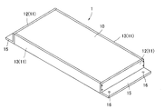
太陽電池モジュール1は、図2で示されるように、太陽電池パネル10の周縁部分にフレーム11を取り付けて形成されるものである。
太陽電池パネル10は、略長方形平板状の部材であり、樹脂製の裏面封止材と、受光面を形成するガラス基板の間に光電変換素子を備えた太陽電池セルを封止して形成される板状の部材である。
フレーム11は、太陽電池パネル10の短辺を覆うように取り付けられる短辺側部材12と、長辺を覆うように取付けられる長辺側部材13を備えており、これらが一体に固定されて四角環状のフレーム11を形成している。
ここで、短辺側部材12の下端近傍には、外側へ向かって突出する平板状の固定板部15が形成されている。
ここで、短辺側部材12の下端近傍には、外側へ向かって突出する平板状の固定板部15が形成されている。
固定板部15は、太陽電池モジュール1の厚さ方向に対して直交する方向に突出する部分であり、平面視した形状が略長方形状となる板状の部分である。この固定板部15は、太陽電池モジュール1の短辺に沿って延びており、その厚さ方向が太陽電池モジュール1の厚さ方向と同一の方向となっている。
なお、太陽電池モジュール1の厚さ方向とは、受光面及び裏面と直交する方向であり、固定板部15の厚さ方向は、表面及び裏面(上端面及び下端面)と直交する方向である。
なお、太陽電池モジュール1の厚さ方向とは、受光面及び裏面と直交する方向であり、固定板部15の厚さ方向は、表面及び裏面(上端面及び下端面)と直交する方向である。
固定板部15には、その長手方向(太陽電池モジュール1の短辺に沿う方向)の片側端部の近傍と、他方側端部の近傍にそれぞれ取付用孔16が設けられている。この取付用孔16は、固定板部15の上端面から下端面に至るまで延びる孔であり、固定板部15を厚さ方向に貫通する孔となっている。
レール部材4は、図3、図4で示されるように、長尺状のレール本体20と、レール本体20の長手方向における端部に取り付けられるエンドキャップ21を備えた構造となっている。
レール本体20は、図4で示されるように、アルミニウム合金等の適宜な金属を加工して形成され、その断面形状が略逆ハット状となる部材である。このレール本体20は、平板状の底板部23と、底板部23の短手方向における両端部分のそれぞれから上方に突出する2つの立板部24と、2つの立板部24のそれぞれの上端から外側に向かって突出する2つの係合板部25(レール側係合部)を備えている。
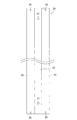
底板部23には、図5で示されるように、複数の固定用孔27が設けられており、それぞれの固定用孔27が底板部23の長手方向で間隔を空けて並列している。いずれの固定用孔27も底板部23の上面から裏面まで延びる孔であり、底板部23を厚さ方向に貫通する孔となっている。
2つの立板部24は、図4で示されるように、レール本体20の短手方向で所定の間隔空けて並列しており、内側面同士が対向した状態となっている。すなわち、2つの立板部24の間であって底板部23の上側となる位置には、これらに囲まれた空間が形成された状態となっている。
係合板部25は、平面視した形状が略長方形状となる平板状の部分であり、いずれもレール本体20の短手方向における中心側から外側へ向かう方向に突出している。すなわち、2つの係合板部25は、互いに離れる方向へ突出している。
この係合板部25には、長手方向において端部よりやや中心よりとなる位置にキャップ取付孔28が設けられている。すなわち、係合板部25には、その長手方向における両端部それぞれの近傍に1つずつ、合計2つのキャップ取付孔28が設けられている。このことから、レール本体20の長手方向における両端部それぞれの近傍に2つずつ、合計4つのキャップ取付孔28が設けられた状態となっている。
いずれのキャップ取付孔28も係合板部25の上面から裏面まで延びる孔であり、係合板部25を厚さ方向に貫通する孔となっている。
いずれのキャップ取付孔28も係合板部25の上面から裏面まで延びる孔であり、係合板部25を厚さ方向に貫通する孔となっている。
エンドキャップ21は、合成ゴム等の弾性材料で形成される部材であり、図4で示されるように、内部に断面形状が略T字状で延びる収納空間29が形成されている。
エンドキャップ21は、略長方形平板状の天面部30と、天面部30の長手方向における両端部それぞれから下方に向かって屈曲しつつ延びる2つの側面形成部31と、天面部30の短手方向における片側端部と連続する正面板部32が一体になって形成されている。
天面部30には、その長手方向における端部よりやや中心よりの位置に取付用孔33が形成されている。すなわち、天面部30には、その長手方向における両端部それぞれの近傍に1つずつ、合計2つの取付用孔33が設けられている。いずれの取付用孔33も天面部30の上面から裏面まで延びており、天面部30を厚さ方向に貫通する孔となっている。
正面板部32は、正面視した形状が略T字状となる立板状の部分であり、天面部30と略垂直に交わっている。
収納空間29は、天面部30と2つの側面形成部31と正面板部32によって囲まれた空間であり、正面板部32と間隔を空けて対向する位置となる側面の一方と、下方とが開放された空間となっている。
この収納空間29は、上記したように断面形状が略T字状となっており、上側部分の断面形状が略横長長方形状であって、下側部分の断面形状が正方形状又は縦長長方形状となっている。
この収納空間29は、上記したように断面形状が略T字状となっており、上側部分の断面形状が略横長長方形状であって、下側部分の断面形状が正方形状又は縦長長方形状となっている。
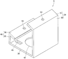
固定片5は、図6、図7で示されるように、平板状の底板部38と、底板部38の対向する2辺のうちの一方から上方に立ち上げられた高側壁部39と、対向する2辺のうちの一方から上方に立ち上げられた低側壁部40を備えた構造となっている。
底板部38には、その大部分を占める領域に開口形状が円形となるレール調整用孔42(レール調整窓部)が形成されている。このレール調整用孔42の開口の中心は、底板部38の上面及び裏面の中心と同位置となっている。すなわち、レール調整用孔42は、底板部38の中心を含み、中心から外側向かって広がる範囲に形成される孔となっている。
また、このレール調整用孔42は、底板部38の上面から裏面まで延びており、底板部38を厚さ方向に貫通する孔となっている。
また、このレール調整用孔42は、底板部38の上面から裏面まで延びており、底板部38を厚さ方向に貫通する孔となっている。
さらに、この底板部38の裏面側には、図8、図9で示されるように、係合突起45(固定片側係合部)が設けられている。この係合突起45は、底板部38の裏面から下方(図8では上方)に突出する立板状部46と、立板状部46の下端側(図8では上端側)を折り曲げて形成される折曲板部47を備えた構造となっている。
ここで、底板部38には複数の係合突起45が設けられており、行列状に配された状態となっている。
より詳細には、高側壁部39よりの位置に形成された第1係合突起45aと、低側壁部40よりの位置に形成された第2係合突起45bとが所定間隔を空けて対向するように並列配置されている。そして、第1係合突起45aと第2係合突起45bからなる組が複数組(本実施形態では2組)形成された状態となっている。このとき、複数の(2つの)第1係合突起45aは、第1係合突起45aと第2係合突起45bの並列方向とは直交する方向で、所定間隔を空けて並列配置されている。そして、複数の(2つの)第2係合突起45bもまた、第1係合突起45aと第2係合突起45bの並列方向とは直交する方向で、所定間隔を空けて並列配置されている。つまり、複数の(2つの)第1係合突起45aによって形成される列と、複数の(2つの)第2係合突起45bによって形成される列が互いに平行となるように配置されている。
より詳細には、高側壁部39よりの位置に形成された第1係合突起45aと、低側壁部40よりの位置に形成された第2係合突起45bとが所定間隔を空けて対向するように並列配置されている。そして、第1係合突起45aと第2係合突起45bからなる組が複数組(本実施形態では2組)形成された状態となっている。このとき、複数の(2つの)第1係合突起45aは、第1係合突起45aと第2係合突起45bの並列方向とは直交する方向で、所定間隔を空けて並列配置されている。そして、複数の(2つの)第2係合突起45bもまた、第1係合突起45aと第2係合突起45bの並列方向とは直交する方向で、所定間隔を空けて並列配置されている。つまり、複数の(2つの)第1係合突起45aによって形成される列と、複数の(2つの)第2係合突起45bによって形成される列が互いに平行となるように配置されている。
そして、図9で示されるように、第1係合突起45aの折曲板部47と第2係合突起45bの折曲板部47は、いずれも内側に折り曲げられている。すなわち、第1係合突起45aの折曲板部47は、低側壁部40に向かう方向に折り曲げられ、第2係合突起45bの折曲板部47は、高側壁部39に向かう方向に折り曲げられている。言い換えると、第1係合突起45aと第2係合突起45bにそれぞれ形成された折曲板部47は、立板状部46の下端から互いに近づく方向に突出した状態となっている。
高側壁部39は、底板部38と連続する立板状の第1壁状部50と、第1壁状部50の上端を内向きに折り曲げて形成される第1モジュール固定部51を備えた構造となっている。つまり、高側壁部39の上端部分には、太陽電池モジュール1を固定するための第1モジュール固定部51が形成された状態となっている。
第1モジュール固定部51は、第1壁状部50の上端から斜め方向である内側上方に突出しており、その上面が傾斜面となっている。すなわち、第1モジュール固定部51の上面は、低側壁部40に近づくにつれて高さが高くなる傾斜面となっている。
この第1モジュール固定部51の長手方向における中心近傍には、モジュール固定孔53が設けられている。モジュール固定孔53は、第1モジュール固定部51の上面から裏面まで延びており、第1モジュール固定部51を厚さ方向に貫通する孔となっている。
この第1モジュール固定部51の長手方向における中心近傍には、モジュール固定孔53が設けられている。モジュール固定孔53は、第1モジュール固定部51の上面から裏面まで延びており、第1モジュール固定部51を厚さ方向に貫通する孔となっている。
低側壁部40は、底板部38と連続する立板状の第2壁状部55と、第2壁状部55の上端を内向きに折り曲げて形成される第2モジュール固定部56を備えた構造となっている。つまり、低側壁部40の上端部分には、第1モジュール固定部51に固定する太陽電池モジュール1とは異なる太陽電池モジュール1を固定するための第2モジュール固定部56が形成された状態となっている。
第2モジュール固定部56は、第2壁状部55の上端から斜め方向である内側下方に突出しており、その上面が傾斜面となっている。すなわち、第2モジュール固定部56の上面は、高側壁部39に近づくにつれて高さが低くなる傾斜面となっている。言い換えると、高側壁部39側から低側壁部40側に向かうにつれて高さが高くなる傾斜面となっている。
この第2モジュール固定部56の長手方向における中心近傍にもまた、モジュール固定孔58が設けられている。モジュール固定孔58は、第2モジュール固定部56の上面から裏面まで延びており、第2モジュール固定部56を厚さ方向に貫通する孔となっている。
この第2モジュール固定部56の長手方向における中心近傍にもまた、モジュール固定孔58が設けられている。モジュール固定孔58は、第2モジュール固定部56の上面から裏面まで延びており、第2モジュール固定部56を厚さ方向に貫通する孔となっている。
ここで、高側壁部39の第1壁状部50は、低側壁部40の第2壁状部55よりも高さ方向(上下方向)に長い部分となっている。このため、第1モジュール固定部51は、第2モジュール固定部56よりも高位置に形成されることとなる。
また、第1モジュール固定部51の第1壁状部50に対する傾斜角度は、第2モジュール固定部56の第2壁状部55に対する傾斜角度と同じ角度となっている。すなわち、第1モジュール固定部51と第2モジュール固定部56は、いずれも高側壁部39側から低側壁部40側に向かうにつれて高さが高くなる傾斜面となっており、その傾斜角度が同じ角度となっている。
また、第1モジュール固定部51の第1壁状部50に対する傾斜角度は、第2モジュール固定部56の第2壁状部55に対する傾斜角度と同じ角度となっている。すなわち、第1モジュール固定部51と第2モジュール固定部56は、いずれも高側壁部39側から低側壁部40側に向かうにつれて高さが高くなる傾斜面となっており、その傾斜角度が同じ角度となっている。
続いて、本実施形態の太陽電池モジュール1の取付構造を構築するための太陽電池モジュール1の取付方法について詳細に説明する。
なお、以下の説明では、屋根面3aのうち、図1のAで示される端部を前端、図1のBで示される端部を後端、図1のCで示される端部を左端、図1のDで示される端部を右端として説明する。
すなわち、傾斜した状態で固定される太陽電池モジュール1を基準として、低位置側を前方とし高位置側を後方とする。つまり、全ての太陽電池モジュール1は、前端側から後端側に向かうにつれて高さが高くなるように傾斜した状態で取り付けられることとなる。さらに、太陽電池モジュール1を低位置側から高位置側へ向かう方向と直交する方向にスライド移動させるとき(詳しくは後述する)、移動起点側を右端とし移動終点側を左端とする。
さらに、最も左端側に位置して前後方向で並列する太陽電池モジュール1の列を第1列目とし、右端側に向かうにつれて第2列目、第3列目、・・・と称する。また、最も後端側に位置して左右方向で並列する太陽電池モジュール1の列を第1段目とし、前端側に向かうにつれて第2段目、第3段目・・・と称する。
なお、以下の説明では、屋根面3aのうち、図1のAで示される端部を前端、図1のBで示される端部を後端、図1のCで示される端部を左端、図1のDで示される端部を右端として説明する。
すなわち、傾斜した状態で固定される太陽電池モジュール1を基準として、低位置側を前方とし高位置側を後方とする。つまり、全ての太陽電池モジュール1は、前端側から後端側に向かうにつれて高さが高くなるように傾斜した状態で取り付けられることとなる。さらに、太陽電池モジュール1を低位置側から高位置側へ向かう方向と直交する方向にスライド移動させるとき(詳しくは後述する)、移動起点側を右端とし移動終点側を左端とする。
さらに、最も左端側に位置して前後方向で並列する太陽電池モジュール1の列を第1列目とし、右端側に向かうにつれて第2列目、第3列目、・・・と称する。また、最も後端側に位置して左右方向で並列する太陽電池モジュール1の列を第1段目とし、前端側に向かうにつれて第2段目、第3段目・・・と称する。
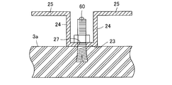
まず、図10、図11で示されるように、屋根面3aに対してレール本体20を固定する。より詳細には、図11で示されるように、屋根面3aに一体に固定されたアンカーボルト60を介して、レール本体20を屋根面3aに固定する。すなわち、屋根面3aから上方に突出するアンカーボルト60の軸部にレール本体20の固定用孔27を挿通した状態とし、底板部23の上側からナットを取り付け、レール本体20を屋根面3aに一体に固定した状態とする。
このとき、複数のレール本体20をそれぞれ所定の間隔を空けて並列配置し、隣接するレール本体20が互いに平行に延びた状態となるように、複数のレール本体20を固定していく(図10参照)。言い換えると、全てのレール本体20が屋根面3aの左右方向に延びた状態となっている。
そして、それぞれのレール本体20では、長手方向の一端側の端部にのみエンドキャップ21(移動規制部材)を取り付け、他端側の端部にはエンドキャップ21を取り付けていない状態とする。詳細には、全てのレール本体20で屋根面3aの左端側に位置する端部にのみエンドキャップ21を取り付け、右端側に位置する端部にはエンドキャップ21を取り付けていない状態とする。つまり、エンドキャップ21は、いずれのレール本体20でも左端側に固定された状態となっており、各レール本体20のエンドキャップ21が取り付けられた端部が、レール本体20の並列方向で所定間隔を空けて並列配置された状態となる。
そして、それぞれのレール本体20では、長手方向の一端側の端部にのみエンドキャップ21(移動規制部材)を取り付け、他端側の端部にはエンドキャップ21を取り付けていない状態とする。詳細には、全てのレール本体20で屋根面3aの左端側に位置する端部にのみエンドキャップ21を取り付け、右端側に位置する端部にはエンドキャップ21を取り付けていない状態とする。つまり、エンドキャップ21は、いずれのレール本体20でも左端側に固定された状態となっており、各レール本体20のエンドキャップ21が取り付けられた端部が、レール本体20の並列方向で所定間隔を空けて並列配置された状態となる。
さらに、太陽電池モジュール1に対して固定片5を固定しておく。
より詳細には、図12で示されるように、太陽電池モジュール1の2つの短辺側部材12の一方に2つの固定片5を固定する。このとき、固定片5の高側壁部39が短辺側部材12よりも太陽電池パネル10に近接する姿勢とした上で、高側壁部39の上端に形成された第1モジュール固定部51の上に固定板部15を載置し、第1モジュール固定部51のモジュール固定孔53と、固定板部15の取付用孔16(図2等参照)を重ね合わせた状態とする。そして、モジュール固定孔53と取付用孔16に締結要素を挿通して、これらを一体に固定する。
なお、締結要素とは、ネジ、釘、ボルト等の上位概念である。
より詳細には、図12で示されるように、太陽電池モジュール1の2つの短辺側部材12の一方に2つの固定片5を固定する。このとき、固定片5の高側壁部39が短辺側部材12よりも太陽電池パネル10に近接する姿勢とした上で、高側壁部39の上端に形成された第1モジュール固定部51の上に固定板部15を載置し、第1モジュール固定部51のモジュール固定孔53と、固定板部15の取付用孔16(図2等参照)を重ね合わせた状態とする。そして、モジュール固定孔53と取付用孔16に締結要素を挿通して、これらを一体に固定する。
なお、締結要素とは、ネジ、釘、ボルト等の上位概念である。
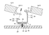
そして、図13、図14で示されるように、太陽電池モジュール1に固定した固定片5の係合突起45をレール本体20の係合板部25と係合させた状態とする。
すなわち、レール本体20の長手方向の端部のうち、エンドキャップ21を取り付けていない端部に対し、固定片5の係合突起45を近接させていき、2つの係合突起45の間に係合板部25が入り込んだ状態とする(図14参照)。このとき、底板部38が係合板部25の上に位置し、係合板部25が係合突起45の折曲板部47より上側に位置した状態となる。つまり、係合板部25が底板部38と折曲板部47に上下から挟まれた状態となり、底板部38と折曲板部47の間に形成される空間に略丁度嵌り込んだ状態となっている。
すなわち、レール本体20の長手方向の端部のうち、エンドキャップ21を取り付けていない端部に対し、固定片5の係合突起45を近接させていき、2つの係合突起45の間に係合板部25が入り込んだ状態とする(図14参照)。このとき、底板部38が係合板部25の上に位置し、係合板部25が係合突起45の折曲板部47より上側に位置した状態となる。つまり、係合板部25が底板部38と折曲板部47に上下から挟まれた状態となり、底板部38と折曲板部47の間に形成される空間に略丁度嵌り込んだ状態となっている。
この状態で、太陽電池モジュール1を固定片5ごと規定位置までスライド移動させていく(図13参照)。すなわち、太陽電池モジュール1及び固定片5をレール本体20の長手方向に沿う方向にスライド移動させ、設置予定位置まで移動させる。
ここで、上記したように、レール本体20の長手方向における端部であり、移動終点側に位置する端部には、エンドキャップ21が取り付けられている(図10等参照)。そして、レール本体20のエンドキャップ21が取り付けられた部分は、固定片5の係合突起45と係合できない状態となっている。すなわち、エンドキャップ21が取り付けられた部分は、周囲の部分よりも厚さが増しており(図3参照)、2つの係合突起45の間に形成される隙間(図14参照)に入り込まない状態となっている。このことから、固定片5がスライド移動して、エンドキャップ21が取り付けられた部分に到達すると、係合突起45がエンドキャップ21に当接し、進行方向へのさらなる移動が阻止される。つまり、エンドキャップ21を取り付けた部分が固定片5のスライド移動を規制する移動規制部として機能する。
このように、エンドキャップ21を取り付けることで、太陽電池モジュール1を固定片5ごとスライド移動させるとき、誤って移動させすぎることがなく、固定片5がレール本体20から脱落してしまうことがない。
そして、図15(a)で示されるように、第1列目であり第1段目に属する太陽電池モジュール1aを規定位置まで移動させ、仮配置(仮固定)した状態とすると、これに続いて、この太陽電池モジュール1aの前側に隣接配置する第1列目であり第2段目に属する太陽電池モジュール1bを同様の手順で仮配置(仮固定)した状態とする。
この状態で、図16で示されるように、前側(第2段目)に仮配置した太陽電池モジュール1bに一体に固定された固定片5に、後側(第1段目)に仮配置した太陽電池モジュール1aの固定板部15を固定する。
すなわち、後側に仮配置した太陽電池モジュール1aのうちで最も低位置となる部分となる前側の固定板部15を、固定片5の第2モジュール固定部56に載置し、固定板部15の取付用孔16(図2等参照)と第2モジュール固定部56のモジュール固定孔58(図6等参照)が重なるように互いの位置を調整する。そして、取付用孔16とモジュール固定孔58にネジ等の締結要素を挿通して一体に固定する。
すなわち、後側に仮配置した太陽電池モジュール1aのうちで最も低位置となる部分となる前側の固定板部15を、固定片5の第2モジュール固定部56に載置し、固定板部15の取付用孔16(図2等参照)と第2モジュール固定部56のモジュール固定孔58(図6等参照)が重なるように互いの位置を調整する。そして、取付用孔16とモジュール固定孔58にネジ等の締結要素を挿通して一体に固定する。
ここで、前側に仮配置した太陽電池モジュール1bと、後側に配置した太陽電池モジュール1aは、いずれも一体に固定した固定片5と共にスライド移動が可能な状態となっている。このため、固定板部15の取付用孔16と第2モジュール固定部56のモジュール固定孔58が重なるように位置合わせをするとき、それぞれを移動させて調整が可能であるため、位置合わせ作業を容易に実施できる。
同様に、第1列目の第3段目以降に属する太陽電池モジュール1を仮配置していき、その後方に隣接する太陽電池モジュール1の前端部分を固定していく。このことにより、第1列目に属する太陽電池モジュール1の取り付けが完了する(図17参照)。
なお、最も前方のレール本体20には、太陽電池モジュール1を固定していない固定片5を係合させ、固定片5のみをスライド移動させる。そして、第1列目のうちで最も前側に設置する太陽電池モジュール1の前端側に位置する固定板部15を、この固定片5に固定する。この最も前端側に位置するレール本体20には、レール本体20を屋根上に取り付けるとき、予め固定片5を係合させておいても構わない。
なお、最も前方のレール本体20には、太陽電池モジュール1を固定していない固定片5を係合させ、固定片5のみをスライド移動させる。そして、第1列目のうちで最も前側に設置する太陽電池モジュール1の前端側に位置する固定板部15を、この固定片5に固定する。この最も前端側に位置するレール本体20には、レール本体20を屋根上に取り付けるとき、予め固定片5を係合させておいても構わない。
続いて、第2列目以降に属する太陽電池モジュール1を順次固定していく。このことにより、図18で示されるように、屋根3の上に設置する全ての太陽電池モジュール1が設置予定位置に取り付けられた状態となる。
この状態で、レール本体20の長手方向における端部であり、移動起点側に位置する端部にもエンドキャップ21を取り付けると、太陽電池モジュール1の屋根3の上への取り付けが完了する。
このようにエンドキャップ21を取り付けることで、太陽電池モジュール1のレール本体20からの脱落を防止できる。
このようにエンドキャップ21を取り付けることで、太陽電池モジュール1のレール本体20からの脱落を防止できる。
ところで、図19で示されるように、固定片5の設置位置と、レール本体20のアンカーボルト60の挿通位置(固定用孔27が形成される位置)が重なってしまう場合がある。すなわち、場所によっては、固定片5の下方側にアンカーボルト60が位置してしまう可能性がある。
ここで、本実施形態の固定片5では、底板部38にレール調整用孔42を形成しているので、固定片5を移動させることなくアンカーボルト60を視認することができる。すなわち、固定片5を移動させることなくナットが正しく締められているか否かの確認や、ナットを締め直したりする作業を実施可能となっている。
ここで、本実施形態の固定片5では、底板部38にレール調整用孔42を形成しているので、固定片5を移動させることなくアンカーボルト60を視認することができる。すなわち、固定片5を移動させることなくナットが正しく締められているか否かの確認や、ナットを締め直したりする作業を実施可能となっている。
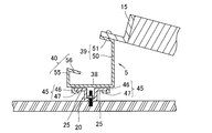
上記した実施形態では、レール本体20の端部で固定片5を係合させ、固定片5をスライド移動させる例について説明した。しかしながら、本発明はこれに限るものではなく、図20、図21でそれぞれ示されるレール部材104や固定片105のように、固定片105をレール部材104の上側から押圧することで、レール部材104と固定片105を係合させてもよい。
このレール部材104と固定片105につき、以下で詳細に説明する。なお、上記した実施形態と同様の部分については、同じ符号を付し、重複する説明を省略する。
このレール部材104と固定片105につき、以下で詳細に説明する。なお、上記した実施形態と同様の部分については、同じ符号を付し、重複する説明を省略する。
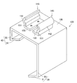
レール部材104は、図20で示されるように、長尺状のレール本体120と、レール本体120の長手方向における端部に取り付けられる端部被覆部材121(移動規制部材)を備えた構造となっている。
レール本体120は、平板状の底板部123と、底板部123の短手方向における両端部分のそれぞれから上方に突出する2つの立板部124と、2つの立板部124のそれぞれの上端から内側に向かって突出する2つの係合板部125(レール側係合部)を備えている。
この底板部123にもまた、上記した底板部23と同様に複数の固定用孔27が設けられている(図示を省略する)。
係合板部125は、平面視した形状が略長方形状となる平板状の部分であり、いずれもレール本体120の短手方向における外側から中心側へ向かう方向に突出している。すなわち、2つの係合板部125は、互いに近づく方向へ突出している。
この係合板部125にもまた、長手方向において端部よりやや中心よりとなる位置に、キャップ取付孔28が設けられている。
この係合板部125にもまた、長手方向において端部よりやや中心よりとなる位置に、キャップ取付孔28が設けられている。
端部被覆部材121は、略L字板状の部材であり、レール本体120の長手方向における端部上面を覆う天面部130と、レール本体120の長手方向における側端面を覆う立板部131を備えており、天面部130と立板部131が略垂直に交わるように連続している。
天面部130には、天面部130を厚さ方向に貫通する取付用孔133が設けられている。より詳細には、天面部130の平面視で対向する2辺のうち、立板部131と連続しない2辺のそれぞれの近傍に1つずつ、合計2つの取付用孔133が設けられている。そして、この2つの取付用孔133が所定間隔を空けて並列した状態となっている。
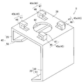
固定片105は、図21で示されるように、平板状の底板部138と、底板部38の対向する2辺のうちの一方から上方(図21では下方)に立ち上げられた高側壁部39と、対向する2辺のうちの一方から上方(図21では下方)に立ち上げられた低側壁部40を備えた構造となっている。
この底板部138の裏面側には、下方(図21では上方)に突出する係合突起145(固定片側係合部)が設けられている。
係合突起145は、略長方形平板状の取付板部150と、取付板部150の外側端部から下方(図21では上方)に突出する立板部151と、立板部151の下端(図21では上端)に連続する湾曲板部152とが一体となって形成されている。
取付板部150は、係合突起145を底板部138の裏面に固定するための部分であり、その上面が底板部138の裏面と密着した状態となっている。そして、取付板部150と底板部138をそれぞれ貫通する締結要素を介して、取付板部150と底板部138が一体に固定されている。
2つの立板部151は、低側壁部40と高側壁部39の並列方向で所定間隔を空けて並列しており、外力が加わらない自然状態において内側面同士が対向した状態となっている。この立板部151は、弾性変形が可能な部分となっている。
湾曲板部152は、外側に膨らむように湾曲する板状の部分であり、断面形状が略半弧形となっている。2つの湾曲板部152もまた、外力が加わらない自然状態において、所定間隔を空けて並列した状態となっている。
続いて、固定片105をレール部材104に係合させる際の動作について、図22を参照しつつ詳細に説明する。
まず、太陽電池モジュール1と一体に固定した固定片105(図22では太陽電池モジュール1の図示を省略する)をレール部材104の上側に配し、2つの係合突起145が2つの係合板部125の間に形成される空間の上側に位置した状態とする(図22(a)参照)。そして、固定片105を下方に移動させていく。
そして、そのまま固定片105を下方に移動させることにより、2つの係合突起145のそれぞれの湾曲板部152が、2つの係合板部125の内側端部と接触した状態となる。この状態で固定片105を下方に押圧することにより、係合板部125から湾曲板部152の曲面を内側へと押圧する力が加わり、湾曲板部152から伝わる力によって立板部151が弾性変形する(図22(b)参照)。すなわち、立板部151が内側へ向かって押されて弾性変形した状態となる。
このことにより、2つの湾曲板部152が一時的に接近し、2つの係合板部125の間を通過可能な状態となる。そして、湾曲板部152が2つの係合板部125の間を通過し、係合板部125の上側から係合板部125の下側へと移動する。
2つの湾曲板部152が底板部123、立板部124、係合板部125に囲まれた空間に配されると(図22(c)参照)、湾曲板部152が他部材と接触しない状態となり、湾曲板部152に外力が加わらず、湾曲板部152から立板部151に伝わる力が解消される。このことにより、係合突起145が元の形状へと戻り、固定片105とレール部材104が係合した状態となる。この状態では、固定片105は、レール部材104の長手方向に沿うようにスライド移動が可能となっている。
なお、固定片105とレール部材104が係合した状態では、2つの係合板部125の間に立板部151が位置しており、2つの係合板部125の下方に湾曲板部152が位置した状態となる。そして、一方の立板部151の外側面から他方の立板部151の外側面までの距離は、2つの係合板部125の間隔と略同一となっている。
また、固定片105とレール部材104が係合した状態では、固定片105に上方へ向かう力を加えても、その力が一定以下である場合には、係合板部125の下面に湾曲板部152が当接してその移動を妨げる。すなわち、一定以上の上方へ向かう力を加えて係合突起145を弾性変形させない限り、係合が解除されない構造となっている。このことにより、太陽電池モジュール1が風等に煽られても、固定片105がレール部材104から外れない構造となっている。
また、固定片105とレール部材104が係合した状態では、固定片105に上方へ向かう力を加えても、その力が一定以下である場合には、係合板部125の下面に湾曲板部152が当接してその移動を妨げる。すなわち、一定以上の上方へ向かう力を加えて係合突起145を弾性変形させない限り、係合が解除されない構造となっている。このことにより、太陽電池モジュール1が風等に煽られても、固定片105がレール部材104から外れない構造となっている。
上記した実施形態では、太陽電池モジュール1の短辺側部材12に固定板部15を形成する例を示したが、本発明はこれに限るものではなく、フレームの長辺側部材に固定板部を形成してもよい。すなわち、設置時の太陽電池モジュールのうちで最も低位置となる部分と最も高位置となる部分を、短辺側でなく長辺側としてもよい。
上記した実施形態では、エンドキャップ21、端部被覆部材121を移動規制部材として採用し、これらを取り付けて移動規制部を形成する例を示したが、本発明の移動規制部材及び移動規制部は、これに限るものではない。例えば、頭部が大型のネジを移動規制部材としてレール本体20の上面に固定し、固定片5の一部をネジの頭部に当接させることで固定片5のスライド移動を規制してもよい。
また、レール本体20の一部を折り曲げ、折り返し等の方法で変形させて歪な形状とし、この変形部分を移動規制部としてもよい。すなわち、固定片5の一部を変形部分に当接させることで固定片5のスライド移動を規制してもよい。
また、レール本体20の一部を折り曲げ、折り返し等の方法で変形させて歪な形状とし、この変形部分を移動規制部としてもよい。すなわち、固定片5の一部を変形部分に当接させることで固定片5のスライド移動を規制してもよい。
上記した実施形態では、建屋の屋根3を太陽電池モジュール1の取り付けの対象物としたが、本発明はこれに限らず、下端部分を地中に埋め込んだ支柱を取り付けの対象物としてもよい。すなわち、レール部材4,104は、屋根面3aに限らず、支柱上に固定してもよい。
上記した実施形態では、太陽電池モジュール1の対向する短辺のうちの1方を第1モジュール固定部51の上に載置し、太陽電池モジュール1と固定片5を一体に固定して、太陽電池モジュール1を屋根面3aの後端側から取り付けていく例を示したが、本発明はこれに限るものではない。
例えば、太陽電池モジュール1の対向する短辺のうちの他方を第2モジュール固定部56の上に載置し、太陽電池モジュール1と固定片5を一体に固定して、太陽電池モジュール1を屋根面3aの前端側から取り付けてもよい。なお、この場合、太陽電池モジュール1に固定する固定片5の姿勢は、上記した取付姿勢から平面視で180度回転した姿勢となる。
例えば、太陽電池モジュール1の対向する短辺のうちの他方を第2モジュール固定部56の上に載置し、太陽電池モジュール1と固定片5を一体に固定して、太陽電池モジュール1を屋根面3aの前端側から取り付けてもよい。なお、この場合、太陽電池モジュール1に固定する固定片5の姿勢は、上記した取付姿勢から平面視で180度回転した姿勢となる。
さらに、レール本体の係合板部の所定の位置と、固定片の底板部の所定の位置に取付孔を形成し、スライド移動させる際にこれらの取付孔を重ね合わせ、スライド移動後に締結要素を挿通してもよい。すなわち、スライド移動後の固定片をレール本体に強固に固定する構造であってもよい。この構造では、取付作業が上記の実施形態と比べて煩雑化するものの、固定片がスライド移動可能であることから、従来の取付具で実施される位置合わせ作業よりも位置合わせ作業が容易に実施可能となる。
1 太陽電池モジュール
2 太陽電池モジュール用取付具
3 屋根(対象物)
4,104 レール部材
5,105 固定片
20,120 レール本体
21 エンドキャップ(移動規制部材)
25,125 係合板部(レール側係合部)
42 レール調整用孔(レール調整窓部)
45,145 係合突起(固定片側係合部)
121 端部被覆部材(移動規制部材)
2 太陽電池モジュール用取付具
3 屋根(対象物)
4,104 レール部材
5,105 固定片
20,120 レール本体
21 エンドキャップ(移動規制部材)
25,125 係合板部(レール側係合部)
42 レール調整用孔(レール調整窓部)
45,145 係合突起(固定片側係合部)
121 端部被覆部材(移動規制部材)
Claims (13)
- 太陽電池モジュールを対象物に取り付けるための太陽電池モジュール用取付具であって、
前記対象物に固定するレール部材と、前記レール部材とは別体であって前記太陽電池モジュールに一体に固定する固定片とを有しており、
前記レール部材はレール側係合部を備えており、前記固定片は固定片側係合部を備えるものであって、前記レール側係合部と前記固定片側係合部が係合することで、前記レール部材と前記固定片が係合可能であり、
前記太陽電池モジュールに一体に固定された前記固定片が前記レール部材と係合した状態で、前記レール部材に沿うようにスライド移動が可能であることを特徴とする太陽電池モジュール用取付具。 - 前記レール部材は、前記固定片のスライド移動を規制する移動規制部を備えていることを特徴とする請求項1に記載の太陽電池モジュール用取付具。
- 前記レール部材は、レール本体と、レール本体とは別体の移動規制部材を備えており、
前記移動規制部材は、前記レール本体に取り付けられて前記レール部材に前記移動規制部を形成するものであって、
前記移動規制部材は、前記レール本体の端部近傍に取り付けられることを特徴とする請求項2に記載の太陽電池モジュール用取付具。 - 前記固定片は、前記レール部材の上方に位置した状態で前記レール部材と係合するものであり、レール調整窓部を備え、
前記レール調整窓部は、前記固定片を上方から視認したとき、前記レール部材の前記固定片と重なる部分を露出させることを特徴とする請求項1乃至3のいずれかに記載の太陽電池モジュール用取付具。 - 前記固定片は、平板状の底板部と、前記底板部の対向する2辺の一方側と他方側にそれぞれ形成された2つの側壁部を備えており、
前記レール調整窓部は、前記底板部を貫通する貫通孔であり、2つの前記側壁部の間に位置していることを特徴とする請求項4に記載の太陽電池モジュール用取付具。 - 前記固定片は、平板状の底板部を備え、
前記底板部の裏面側には、前記固定片側係合部を構成する複数の係合突起が設けられており、複数の前記係合突起には、所定間隔を空けて並列配置される第1係合突起と第2係合突起が含まれるものであり、
前記第1係合突起及び前記第2係合突起は、前記底板部の裏面から下方に突出する立板状部と、前記立板状部の下端側を折り曲げて形成される折曲板部とを有しており、
前記第1係合突起の前記折曲板部と前記第2前記係合突起の前記折曲板部は、互いに近づく方向に突出した状態となるように、それぞれが折り曲げられていることを特徴とする請求項1乃至5のいずれかに記載の太陽電池モジュール用取付具。 - 前記固定片は、平板状の底板部を備え、
前記底板部の裏面側には、前記固定片側係合部を構成する複数の係合突起が設けられており、
前記係合突起は、立板部と、前記立板部の下端と連続する湾曲板部を備え、且つ、弾性変形可能な部分を有するものであり、
2つの前記係合突起が所定間隔を空けて並列配置され、2つの前記立板部がその内側面同士が対向した状態となっており、2つの前記湾曲板部がそれぞれ外側に膨らむように湾曲していることを特徴とする請求項1乃至5のいずれかに記載の太陽電池モジュール用取付具。 - 前記移動規制部材は、前記レール本体の端部上面を覆う天面部を少なくとも有していることを特徴とする請求項3に記載の太陽電池モジュール用取付具。
- 前記移動規制部材は、平板状の天面部と、天面部から下方に向かって延びる2つの側面形成部と、正面板部とを備えており、
前記移動規制部材の内部には、前記天面部、2つの前記側面形成部、前記正面板部によって囲まれた空間である収納空間が形成され、
前記収納空間は、前記レール本体の端部を収納可能であることを特徴とする請求項8に記載の太陽電池モジュール用取付具。 - 前記移動規制部材は、重ねた状態の前記天面部及び前記レール本体の双方を貫通する締結要素を介し、前記レール本体に対して一体に固定されるものであることを特徴とする請求項8又は9に記載の太陽電池モジュール用取付具。
- 請求項1乃至10のいずれかに記載の太陽電池モジュール用取付具を使用して、複数の太陽電モジュールを隣接させた状態で前記対象物に取り付ける太陽電池モジュールの取付方法であって、
前記対象物に前記レール部材を固定する工程と、
前記太陽電池モジュールに前記固定片を固定する工程と、
前記太陽電池モジュールに固定された前記固定片を前記レール部材に係合させ、前記太陽電池モジュール及び前記固定片をスライド移動させる工程と、
前記太陽電池モジュールの一部を、隣接する位置に配された他の前記太陽電池モジュールに固定される前記固定片に対して固定する工程とを実施することを特徴とする太陽電池モジュールの取付方法。 - 前記太陽電池モジュールに前記固定片を固定する工程では、前記太陽電池モジュールの傾斜方向で対向する2辺のうち、一方側にのみ前記固定片を固定することを特徴とする請求項11に記載の太陽電池モジュールの取付方法。
- 請求項3に記載の太陽電池モジュール用取付具を使用して、複数の太陽電モジュールを隣接させた状態で前記対象物に取り付ける太陽電池モジュールの取付方法であって、
前記対象物に前記レール部材を固定する工程と、
前記太陽電池モジュールに前記固定片を固定する工程と、
前記太陽電池モジュールに固定された前記固定片を前記レール部材に係合させ、前記太陽電池モジュール及び前記固定片をスライド移動させる工程と、
前記太陽電池モジュールの一部を、隣接する位置に配された他の前記太陽電池モジュールに固定される前記固定片に対して固定する工程とを実施するものであり、
前記前記太陽電池モジュール及び前記固定片をスライド移動させる工程に先立って、前記レール本体の片側端部に前記移動規制部材を固定する工程を実施し、
前記前記太陽電池モジュール及び前記固定片をスライド移動させる工程の後に、前記レール本体の他方側端部に前記移動規制部材を固定する工程を実施することを特徴とする太陽電池モジュールの取付方法。
Priority Applications (1)
| Application Number | Priority Date | Filing Date | Title |
|---|---|---|---|
| JP2017508269A JP6725493B2 (ja) | 2015-03-26 | 2016-03-16 | 太陽電池モジュール用取付具及び太陽電池モジュールの取付方法 |
Applications Claiming Priority (2)
| Application Number | Priority Date | Filing Date | Title |
|---|---|---|---|
| JP2015-064350 | 2015-03-26 | ||
| JP2015064350 | 2015-03-26 |
Publications (1)
| Publication Number | Publication Date |
|---|---|
| WO2016152680A1 true WO2016152680A1 (ja) | 2016-09-29 |
Family
ID=56978423
Family Applications (1)
| Application Number | Title | Priority Date | Filing Date |
|---|---|---|---|
| PCT/JP2016/058346 Ceased WO2016152680A1 (ja) | 2015-03-26 | 2016-03-16 | 太陽電池モジュール用取付具及び太陽電池モジュールの取付方法 |
Country Status (2)
| Country | Link |
|---|---|
| JP (1) | JP6725493B2 (ja) |
| WO (1) | WO2016152680A1 (ja) |
Cited By (4)
| Publication number | Priority date | Publication date | Assignee | Title |
|---|---|---|---|---|
| JP2021102890A (ja) * | 2019-12-25 | 2021-07-15 | 京セラ株式会社 | 太陽電池アレイおよび取付具ユニット |
| US20220416715A1 (en) * | 2021-06-29 | 2022-12-29 | Arka Energy Inc. | System for mounting tiles over a surface |
| US11545929B2 (en) | 2019-02-07 | 2023-01-03 | United States Department Of Energy | Solar panel racking system |
| EE01617U1 (et) * | 2023-03-16 | 2023-11-15 | Restartum OÜ | Päikesepaneeli kinnitusseade |
Citations (2)
| Publication number | Priority date | Publication date | Assignee | Title |
|---|---|---|---|---|
| JP2005175236A (ja) * | 2003-12-12 | 2005-06-30 | Canon Inc | 太陽電池モジュール |
| US20090114271A1 (en) * | 2007-09-02 | 2009-05-07 | Robert Stancel | Slidable Mounting System for Solar Modules |
-
2016
- 2016-03-16 WO PCT/JP2016/058346 patent/WO2016152680A1/ja not_active Ceased
- 2016-03-16 JP JP2017508269A patent/JP6725493B2/ja active Active
Patent Citations (2)
| Publication number | Priority date | Publication date | Assignee | Title |
|---|---|---|---|---|
| JP2005175236A (ja) * | 2003-12-12 | 2005-06-30 | Canon Inc | 太陽電池モジュール |
| US20090114271A1 (en) * | 2007-09-02 | 2009-05-07 | Robert Stancel | Slidable Mounting System for Solar Modules |
Cited By (6)
| Publication number | Priority date | Publication date | Assignee | Title |
|---|---|---|---|---|
| US11545929B2 (en) | 2019-02-07 | 2023-01-03 | United States Department Of Energy | Solar panel racking system |
| JP2021102890A (ja) * | 2019-12-25 | 2021-07-15 | 京セラ株式会社 | 太陽電池アレイおよび取付具ユニット |
| JP7360935B2 (ja) | 2019-12-25 | 2023-10-13 | 京セラ株式会社 | 太陽電池アレイおよび取付具ユニット |
| US20220416715A1 (en) * | 2021-06-29 | 2022-12-29 | Arka Energy Inc. | System for mounting tiles over a surface |
| WO2023275629A1 (en) * | 2021-06-29 | 2023-01-05 | Arka Energy Inc. | System for mounting tiles over a surface |
| EE01617U1 (et) * | 2023-03-16 | 2023-11-15 | Restartum OÜ | Päikesepaneeli kinnitusseade |
Also Published As
| Publication number | Publication date |
|---|---|
| JP6725493B2 (ja) | 2020-07-22 |
| JPWO2016152680A1 (ja) | 2018-01-18 |
Similar Documents
| Publication | Publication Date | Title |
|---|---|---|
| US11936332B2 (en) | Waterproofing mounting system for attaching solar modules to a roof | |
| US20120312356A1 (en) | Solar cell module | |
| EP3060861B1 (en) | Solar panel mechanical connector and frame | |
| US9923511B2 (en) | Connecting solar modules | |
| US20180062570A1 (en) | Mounting structure for solar cell module and mounting tool | |
| US20160043688A1 (en) | Solar panel installation systems and methods | |
| US9188365B2 (en) | Frame for supporting solar module | |
| US20100065108A1 (en) | Method and Apparatus for Forming and Mounting a Photovoltaic Array | |
| EP2169139A1 (en) | Fixing structure of solar battery module, frame for the solar battery module, and fixing member | |
| US20130136531A1 (en) | Plate-like module securing structure | |
| KR101726805B1 (ko) | 태양광 패널체 고정용 클램프 | |
| JP5936068B2 (ja) | 太陽電池モジュール用取付金具、及び施工方法 | |
| EP3099984B1 (en) | Solar photovoltaic module clamping system and solar carport | |
| US20130263917A1 (en) | Solar Battery Module Fixture | |
| JPWO2016152680A1 (ja) | 太陽電池モジュール用取付具及び太陽電池モジュールの取付方法 | |
| US10187006B2 (en) | Wedge spring clip mounting system for photovoltaic modules | |
| US9923509B2 (en) | Spring loaded mounting foot for photovoltaic systems | |
| EP2944739B1 (en) | Retaining device for solar cell module | |
| US20200347865A1 (en) | Section-steel joint | |
| WO2018008620A1 (ja) | 太陽電池モジュールの固定具 | |
| US10224864B2 (en) | Solar cell module mounting device | |
| JP2005264441A (ja) | 太陽電池アレイ | |
| JP2020036390A (ja) | 太陽光発電パネル固定装置 | |
| JP5686771B2 (ja) | 太陽電池モジュールの固定構造、及び太陽電池モジュールの固定方法 | |
| JP5457855B2 (ja) | 太陽電池モジュールの取付具及び取付構造 |
Legal Events
| Date | Code | Title | Description |
|---|---|---|---|
| 121 | Ep: the epo has been informed by wipo that ep was designated in this application |
Ref document number: 16768583 Country of ref document: EP Kind code of ref document: A1 |
|
| ENP | Entry into the national phase |
Ref document number: 2017508269 Country of ref document: JP Kind code of ref document: A |
|
| NENP | Non-entry into the national phase |
Ref country code: DE |
|
| 122 | Ep: pct application non-entry in european phase |
Ref document number: 16768583 Country of ref document: EP Kind code of ref document: A1 |