WO2016152435A1 - 吸気ポート - Google Patents
吸気ポート Download PDFInfo
- Publication number
- WO2016152435A1 WO2016152435A1 PCT/JP2016/056554 JP2016056554W WO2016152435A1 WO 2016152435 A1 WO2016152435 A1 WO 2016152435A1 JP 2016056554 W JP2016056554 W JP 2016056554W WO 2016152435 A1 WO2016152435 A1 WO 2016152435A1
- Authority
- WO
- WIPO (PCT)
- Prior art keywords
- intake port
- composite material
- material portion
- filler
- porous plate
- Prior art date
- Legal status (The legal status is an assumption and is not a legal conclusion. Google has not performed a legal analysis and makes no representation as to the accuracy of the status listed.)
- Ceased
Links
Images


Classifications
-
- F—MECHANICAL ENGINEERING; LIGHTING; HEATING; WEAPONS; BLASTING
- F02—COMBUSTION ENGINES; HOT-GAS OR COMBUSTION-PRODUCT ENGINE PLANTS
- F02B—INTERNAL-COMBUSTION PISTON ENGINES; COMBUSTION ENGINES IN GENERAL
- F02B77/00—Component parts, details or accessories, not otherwise provided for
- F02B77/11—Thermal or acoustic insulation
-
- F—MECHANICAL ENGINEERING; LIGHTING; HEATING; WEAPONS; BLASTING
- F02—COMBUSTION ENGINES; HOT-GAS OR COMBUSTION-PRODUCT ENGINE PLANTS
- F02F—CYLINDERS, PISTONS OR CASINGS, FOR COMBUSTION ENGINES; ARRANGEMENTS OF SEALINGS IN COMBUSTION ENGINES
- F02F1/00—Cylinders; Cylinder heads
- F02F1/24—Cylinder heads
-
- F—MECHANICAL ENGINEERING; LIGHTING; HEATING; WEAPONS; BLASTING
- F02—COMBUSTION ENGINES; HOT-GAS OR COMBUSTION-PRODUCT ENGINE PLANTS
- F02F—CYLINDERS, PISTONS OR CASINGS, FOR COMBUSTION ENGINES; ARRANGEMENTS OF SEALINGS IN COMBUSTION ENGINES
- F02F1/00—Cylinders; Cylinder heads
- F02F1/24—Cylinder heads
- F02F1/42—Shape or arrangement of intake or exhaust channels in cylinder heads
Definitions
- the present invention relates to an intake port including a composite material portion formed of a composite material with improved heat insulation effect.
- pre-ignition is caused by overheating of the air-fuel mixture before combustion (air / gasoline mixture) due to the high intake air temperature.
- the engine member (cylinder head) itself is at a high temperature, the intake air is heated by the movement of the intake air to the intake air, and the intake air may become high temperature.
- the invention described in Patent Document 1 forms a heat insulating layer made of a metal porous body and a coating on the surface of the engine component facing the engine combustion chamber, the inner wall surface of the intake port or the inner wall surface of the exhaust port, and By trying to reduce fuel consumption, we are trying to improve fuel efficiency.
- the heat insulating layer has low thermal conductivity and low heat capacity.
- Patent Document 2 provides a cylinder head of an internal combustion engine provided with an intake port capable of obtaining an effect of suppressing a rise in temperature of intake air. This is formed of a material having low thermal conductivity and low specific heat. In this way, the occurrence of knocking is suppressed and fuel efficiency is improved.
- an intake port with lower thermal conductivity is desired.
- the intake air is cooled by latent heat when the fuel is vaporized.
- the cooled state is insulated from external heat, so that the effect of suppressing the occurrence of pre-ignition is increased.
- water may be injected into the intake port, and the same effect can be expected when using an intake port with low thermal conductivity.
- An object of the present invention is to provide an intake port having a heat insulating effect so that intake air flowing into an engine combustion chamber is not warmed by heat of an engine member.
- the present inventors have a plate shape with an aspect ratio of 3 or more, a minimum length of 0.1 to 50 ⁇ m, a total porosity of 20 to 90%, a synthetic resin, It has been found that the above problem is solved by an intake port including a composite material portion formed of a composite material including That is, according to the present invention, the following intake ports are provided.
- a composite comprising a plate-like plate having an aspect ratio of 3 or more, a minimum length of 0.1 to 50 ⁇ m, and an overall porosity of 20 to 90%, and a synthetic resin.
- An intake port comprising a composite part formed of material.
- the porous plate filler is at least one selected from metal oxides of zirconia, partially stabilized zirconia, fully stabilized zirconia, yttrium oxide, alumina, silica, titania, niobium oxide, strontium oxide, and lanthanum oxide.
- the intake port according to any one of [1] to [14], including one.
- the intake port of the present invention has a plate shape with an aspect ratio of 3 or more, a minimum length of 0.1 to 50 ⁇ m, an overall porosity of 20 to 90%, a synthetic resin, The composite material part formed with the composite material containing these. For this reason, the intake port has low thermal conductivity, insulates the heat of the engine member such as the cylinder head, and suppresses that the intake gas is heated by the heat from the engine member before being sucked into the engine combustion chamber. be able to. Thereby, pre-ignition can be suppressed and thermal efficiency can be improved (fuel efficiency improvement). That is, it is advantageous in increasing the efficiency of charging the intake air into the engine combustion chamber.
- Intake Port FIG. 1 is a partial sectional view of the engine 10.
- the cylinder head 13 set at the upper part of the cylinder block is provided with an intake port 18 and an exhaust port 19, and further, an intake valve 16, an exhaust valve 17, a spark plug 15 and the like are set.
- the temperature rise of the intake gas is suppressed by providing the intake port 18 having a heat insulating effect.
- the intake port 18 of the present invention includes the composite material portion 3.
- the composite material portion 3 has a plate shape with an aspect ratio of 3 or more, a minimum length of 0.1 to 50 ⁇ m, and an overall porosity of 20 to 90%, and a synthetic resin 2 And a composite material including The composite material contains 50% by mass or more of the porous plate-like filler 1 and the synthetic resin 2 together.
- Such a composite material part 3 has a heat insulating effect.
- the intake port 18 of the present invention includes the composite material portion 3 on the intake gas side of the intake port 18, and when the intake gas contacts the composite material portion 3, the surface of the composite material portion 3, that is, the composite material portion 3.
- the unevenness (maximum height Ry: JIS B0601 (1994)) on the surface of the intake gas side is 10 ⁇ m or less. More preferably, it is 7 micrometers or less, More preferably, it is 5 micrometers or less.
- the unevenness of the surface of the composite material part 3 is 10 ⁇ m or less, the intake gas can be circulated efficiently even if the composite material part 3 is provided.
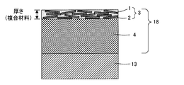
- FIG. 2 is a diagram showing the first embodiment of the present invention, and is an explanatory diagram showing a part of a cross section of the intake port 18 composed of the composite material portion 3 and the metal portion 4.
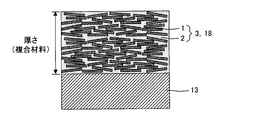
- FIG. 3 is a view showing Embodiment 2 of the present invention, and is an explanatory view showing a part of a cross section of the intake port 18 composed only of the composite material portion 3.
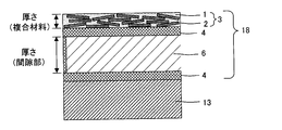
- FIG. 4 is a view showing a third embodiment of the present invention, and is an explanatory view showing a part of a cross section of the intake port 18 constituted by the composite material portion 3, the metal portion 4 and the gap portion 6.
- the intake port 18 of this embodiment is shown in FIG.
- the intake port 18 of the present embodiment is preferably constituted by the composite material part 3 and the metal part 4.
- the metal part 4 is formed of a metal, and can be formed of, for example, an aluminum alloy or an iron alloy.
- the intake port 18 preferably has the composite material portion 3 disposed on the intake gas side and the metal portion 4 disposed on the cylinder head 13 side. Further, the thickness of the composite material portion 3 of the intake port 18 is preferably 0.01 to 1 mm. More preferably, the composite material portion 3 has a thickness of 0.03 to 0.5 mm, and more preferably 0.05 to 0.2 mm. When the composite material part 3 is 0.01 mm or more, the heat insulation is good.
- Such an intake port 18 can be produced, for example, by applying a slurry containing the porous plate filler 1 and the synthetic resin 2 to the inner wall of a metal tube and drying the slurry.
- the intake port 18 of this embodiment is shown in FIG. It is preferable that the intake port 18 of this embodiment is comprised only by the composite material part 3.
- FIG. the intake port 18 is preferably formed as a tube of the cylindrical composite material portion 3. By fitting such a pipe of the composite material portion 3 into the cylinder head 13, it can be used as an intake port 18 composed only of the composite material portion 3.
- the intake port 18 constituted only by the composite material portion 3 has a high heat insulating effect.
- the thickness of the composite material portion 3 constituting the intake port 18 of the second embodiment is 1 to 10 mm. More preferably, the composite material portion 3 has a thickness of 1.2 to 9.5 mm, and more preferably 1.5 to 9 mm. When the thickness of the composite material portion 3 is 1 mm or more, a heat insulating effect is easily obtained.
- Such an intake port 18 can be manufactured by extruding a mixture containing the porous plate filler 1 and the synthetic resin 2. The intake port 18 can be manufactured by injection molding or hollow molding.
- the composite material portion 3 is preferably as thick as possible. However, if the composite material portion 3 is too thick, the component itself becomes large and the mountability deteriorates.
- the first embodiment easily achieves 0.01 to 1 mm, and the second embodiment easily realizes 1 to 10 mm. In the first embodiment, it is not easy to increase the thickness to 1 mm or more, while in the second embodiment, it is not easy to reduce the thickness to 1 mm or less.
- the intake port 18 of this embodiment is shown in FIG.
- the intake port 18 of the present embodiment is preferably composed of the composite material part 3, the metal part 4 containing metal, and the gap part 6. Since the intake port 18 includes the composite material portion 3 and the gap portion 6, the heat insulation effect can be improved.
- the metal part 4 it is preferable to use a double-pipe-shaped metal pipe.
- the gap part 6 refers to a gap of the double pipe structure.
- the composite material part 3 is arrange
- the thickness of the composite material portion 3 of the intake port 18 of Embodiment 3 is preferably 0.01 to 1 mm, more preferably 0.03 to 0.5 mm, and even more preferably 0.05 to 0.2 mm.
- the thickness of the composite material part 3 is 0.01 mm or more, the heat insulation is good. Further, when the composite material portion 3 is 1 mm or less, the composite material portion 3 is difficult to peel off, and the component itself is prevented from becoming large and the mountability is good.
- the thickness of the gap 6 is preferably 0.1 to 1 mm, more preferably 0.2 to 0.8 mm, and still more preferably 0.3 to 0.6 mm.
- the thickness of the gap 6 is 0.1 mm or more, the heat insulation is good. Further, when the gap 6 is 1 mm or less, the gap 6 is difficult to peel off, and the component itself is prevented from becoming large, and the mountability is good.
- a double pipe of the metal part 4 is prepared, and a slurry containing the porous plate filler 1 and the synthetic resin 2 is applied to the inside of the double pipe (intake gas side) and dried.
- the film of the composite material portion 3 can be formed and manufactured.
- Composite Material Part 3 included in the intake port 18 of the present invention is formed of a composite material including the porous plate filler 1 and the synthetic resin 2.
- the composite material may contain components other than the porous plate-like filler 1 and the synthetic resin 2.
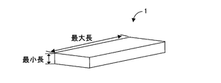
- porous Plate Filler 1 An example of the porous plate filler 1 is shown in FIG.
- the porous platy filler 1 contained in the composite material part 3 of the present invention is a plate having an aspect ratio of 3 or more, the minimum length is 0.1 to 50 ⁇ m, and the overall porosity is 20 to 90%. is there.
- the porosity of the porous plate filler 1 is preferably 20 to 90%, more preferably 40 to 85%, and still more preferably 50 to 80%. By setting the porosity to 20% or more, the thermal conductivity can be lowered. Moreover, strength can be ensured by setting the porosity to 90% or less.
- the aspect ratio of the porous plate-like filler 1 is defined by the maximum length / minimum length of the porous plate-like filler 1.
- the maximum length is the maximum length when the particles (porous plate filler 1) are sandwiched between a pair of parallel surfaces.
- the minimum length is the minimum length when the particles are sandwiched between a pair of parallel surfaces, and corresponds to a so-called thickness in the case of a flat plate shape.
- the plate shape of the porous plate filler 1 is not only a flat plate shape (a flat and uncurved plate) as long as the aspect ratio is 3 or more and the minimum length is 0.1 to 50 ⁇ m, A curved plate or a plate whose thickness (minimum length) is not constant is also included.
- the shape may be a fiber shape, a needle shape, a lump shape, or the like.
- the porous plate-like filler 1 has a flat plate shape.
- the surface shape of the plate may be any shape such as a square, a square, a triangle, a hexagon, and a circle. That is, the porous plate-like filler 1 may have any shape as long as it is plate-like.
- the aspect ratio of the porous plate filler 1 is preferably 3 or more.
- the aspect ratio is too large, handling in manufacturing becomes difficult, and the yield may be deteriorated.
- the minimum length is shortened to increase the aspect ratio, the strength may not be sufficient.
- the maximum length is increased, the porous plate-like filler 1 becomes large and may be damaged.
- the aspect ratio is more preferably 3 or more and 50 or less, further preferably 3.5 or more and 40 or less, and most preferably 4 or more and 30 or less.
- the minimum length of the porous plate filler 1 is 0.1 to 50 ⁇ m, more preferably 0.5 to 20 ⁇ m, still more preferably 2 to 15 ⁇ m, and most preferably 2 to 10 ⁇ m. If the minimum length of the porous plate-like filler 1 is shorter than 0.1 ⁇ m, it may be difficult to maintain the shape of the porous plate-like filler 1 during the manufacturing process. If the minimum length of the porous plate-like filler 1 is longer than 50 ⁇ m, the number of layers of the porous plate-like filler 1 is reduced when the porous plate-like filler 1 is included in the composite material portion 3. In some cases, the thermal conductivity of the composite material part 3 is increased. Moreover, when the minimum length of the porous plate-like filler 1 is short, the composite material part 3 can be made thin. That is, even if it is the thin composite material part 3, the heat insulation effect can be improved.
- the porous plate-like filler 1 preferably contains a metal oxide, and more preferably consists only of a metal oxide.
- a metal oxide is included, since the ionic bond between the metal and oxygen is stronger than that of a metal non-oxide (for example, carbide or nitride), the thermal conductivity tends to be low.
- the porous plate-like filler 1 is selected from the group consisting of metal oxides Zr, Y, Al, Si, Ti, Nb, Sr, La, Hf, Ce, Gd, Sm, Mn, Yb, Er, and Ta. It is preferably an oxide of one element or a composite oxide of two or more elements. When the metal oxide is an oxide or composite oxide of these elements, heat conduction due to lattice vibration (phonon), which is the main cause of heat conduction, is difficult to occur.
- Specific materials for the porous plate-like filler 1 include those obtained by adding Gd 2 O 3 , Yb 2 O 3 , Er 2 O 3 or the like to ZrO 2 —Y 2 O 3 .
- the porous plate-like filler 1 may be an inorganic material, an organic material, or a composite material of an inorganic material and an organic material.
- zirconia partially stabilized zirconia (for example, yttria partially stabilized zirconia), fully stabilized zirconia (for example, yttria fully stabilized zirconia), yttrium oxide, alumina, silica, titania, niobium oxide, strontium oxide, lanthanum oxide, Zirconium, yttria, aluminum, silicon, titanium, niobium, strontium, lanthanum, rare earth zirconate (eg lanthanum zirconate), rare earth silicate (eg yttrium silicate), niobate (eg strontium niobate), Inorganic materials such as mullite, mica, spinel, zircon, magnesia, ceria, silicon carbide, silicon nitride, aluminum
- Metals such as zirconia, partially stabilized zirconia (eg, yttria partially stabilized zirconia), fully stabilized zirconia (eg, yttria fully stabilized zirconia), yttrium oxide, alumina, silica, titania, niobium oxide, strontium oxide, lanthanum oxide, etc. More preferably, it is an oxide. These may be used alone or in combination of two or more.
- the porous plate-like filler 1 preferably has a thermal conductivity of 1 W / (m ⁇ K) or less.
- the thermal conductivity is more preferably 0.7 W / (m ⁇ K) or less, further preferably 0.5 W / (m ⁇ K) or less, and most preferably 0.3 W / (m ⁇ K) or less.
- the porous plate-like filler 1 having such a thermal conductivity is included in the composite material portion 3, the heat insulating effect can be improved.
- thermal diffusivity is measured by the optical alternating current method.
- Specific heat is measured by DSC method.
- Density is measured with a mercury porosimeter.
- the porous plate-like filler 1 preferably has a heat capacity of 10 to 3000 kJ / (m 3 ⁇ K).
- the heat capacity is more preferably 10 to 2500 kJ / (m 3 ⁇ K), further preferably 300 to 2000 kJ / (m 3 ⁇ K), and most preferably 400 to 1500 kJ / (m 3 ⁇ K).
- the porous plate-like filler 1 having a heat capacity in such a range is included in the composite material portion 3, the heat insulating effect can be improved.
- the heat capacity is generally discussed per unit volume called volume specific heat, the unit is kJ / (m 3 ⁇ K).
- the synthetic resin 2 preferably contains at least one of silicone, polyimide, polyamide, acrylic, and epoxy. Among these, silicone and polyimide with high heat resistance are particularly preferable.
- the synthetic resin 2 is a component that exists around the porous plate-like filler 1 and between these particles, and is a component that binds between these particles.
- the composite material part 3 of the present invention is a plate-like filler having an aspect ratio of 3 or more, a minimum length of 0.1 to 50 ⁇ m, and an overall porosity of 20 to 90%. 1 and a composite material including a synthetic resin 2.
- the composite material contains 50% by mass or more of the porous plate filler 1 and the synthetic resin 2.
- the composite material contains 90% by mass or more of the porous plate filler 1 and the synthetic resin 2, and it is more preferable that the composite material consists only of the porous plate filler 1 and the synthetic resin 2.
- the porous plate-like filler 1 is preferably arranged (laminated) in layers.
- the term “layered arrangement” as used herein means that the porous plate filler 1 is synthesized in a state in which the minimum length of the porous plate filler 1 is oriented in the direction perpendicular to the longitudinal direction of the composite material portion 3. It is present in the resin 2. At this time, it is not necessary to arrange them regularly and regularly, and they may exist randomly. There is no problem as long as the number of stacked layers is 1 or more, but a larger number of stacked layers is preferable, and 5 or more is desirable.
- the porous plate-like filler 1 Since the porous plate-like filler 1 is laminated in the composite material portion 3, the heat transfer path is refracted and lengthened, and the heat insulating effect can be improved. In particular, it is preferable that the porous plate-like fillers 1 are not arranged in order (they are staggered) because the heat transfer path is refracted and becomes longer.
- the angle between the minimum length direction of the porous plate-like filler 1 and the longitudinal direction of the intake port 18 is preferably 45 ° to 90 °. This means that the average value when 10 porous plate-like fillers 1 are measured is 45 ° to 90 °.
- the intake port 18 including the composite material portion 3 in which the angle between the minimum length direction of the porous plate filler 1 and the longitudinal direction of the intake port 18 is 45 ° to 90 ° is effectively heated by the porous plate filler 1. And the thermal conductivity of the composite material part 3 can be reduced. That is, the heat insulation effect can be enhanced.
- the porous plate-like filler 1 is dispersed in the synthetic resin 2 for binding the porous plate-like filler 1, and the volume ratio of the porous plate-like filler 1: the synthetic resin 2 is 50: It is preferably 50 to 95: 5. More preferably, it is 60:40 to 90:10, and still more preferably 70:30 to 85:15.
- the volume ratio of the porous plate filler 1 and the synthetic resin 2 is within this range, the thermal conductivity can be further lowered. Thereby, the thickness of the composite material part 3 can be reduced. Therefore, the space for disposing the composite material portion 3 can be reduced, and the cost can be reduced.
- the synthetic resin 2 having a function of binding the porous plate-like filler 1 can easily exert a sufficient binding force, and the peeling of the porous plate-like filler 1 can be prevented. That is, the strength of the film can be improved. Furthermore, the thermal stress can be lowered during bonding with different materials. As described above, if the porous plate-like filler 1 is large, the heat insulating effect can be improved, and if the synthetic resin 2 is large, the strength of the film can be improved. By setting the volume ratio of the porous plate-like filler 1 and the synthetic resin 2 to the above range, both heat insulating properties and film strength can be achieved.
- the composite material part 3 of the present invention preferably has a thermal conductivity in the thickness direction of 1.5 W / (m ⁇ K) or less.
- the composite material portion 3 is more preferably 1 W / (m ⁇ K) or less, and most preferably 0.5 W / (m ⁇ K) or less. Heat transfer can be suppressed by having low thermal conductivity.
- Composite material portion 3 of the present invention preferably has heat capacity is 1500kJ / (m 3 ⁇ K) or less, more preferably 1300kJ / (m 3 ⁇ K) or less, 1000kJ / (m 3 ⁇ K ) Or less, and most preferably 500 kJ / (m 3 ⁇ K) or less. Due to the low heat capacity, the composite material part 3 is less likely to have heat, and the heat is less likely to transfer to the intake air. Therefore, the intake air tends to be low temperature.
- Example 1 An intake port 18 in which the composite material portion 3 was disposed on the intake gas side and the metal portion 4 was disposed on the cylinder head 13 side was produced (FIG. 2: Embodiment 1). Specifically, the composite material portion 3 having a thickness of 100 ⁇ m was provided inside the same aluminum alloy tube as that of Comparative Example 1. This composite material part 3 contained the porous plate-like filler 1 and the synthetic resin 2 listed in Table 1. The slurry is weighed so that the volume ratio of the porous plate-like filler 1: synthetic resin 2 is 50:50, and the slurry is applied to the inner wall of the aluminum alloy tube by spraying and dried, whereby the intake port 18 is formed. Produced.
- Example 2 (Examples 2 and 3) In the same manner as in Example 1, the intake port 18 of Examples 2 and 3 was produced. Specific values are shown in Table 1.
- Example 4 An intake port 18 composed only of the composite material part 3 was produced (FIG. 3: Embodiment 2).
- the composite material portion 3 includes a porous plate-like filler 1 and a synthetic resin 2 described in Table 1.
- a composite material having a diameter of 98 mm, a length of 500 mm, and a thickness of 1 mm is obtained by weighing the porous plate-like filler 1: the synthetic resin 2 so that the volume ratio is 50:50 and extruding it.
- a tube formed by part 3 was formed. Next, the tube of the composite material part 3 was fitted into the inner wall of an aluminum alloy tube having a diameter of 100 mm—a length of 500 mm—a thickness of 1 mm.
- Example 5 In the same manner as in Example 4, intake ports 18 of Examples 5 and 6 were produced. Specific values are shown in Table 1.
- An intake port 18 composed of the composite material part 3, the metal part 4, and the gap part 6 was produced (FIG. 4: Embodiment 3).
- the composite material portion 3 contained the porous plate-like filler 1 and the synthetic resin 2 listed in Table 1.
- an aluminum alloy double pipe is prepared (diameter 100 mm-length 500 mm-outer wall thickness 1 mm, gap 6 thickness 2 mm, inner wall thickness 1 mm), and inside the double pipe (intake air) A film of the composite material portion 3 was formed on the gas side) in the same manner as in Example 1, and the intake port 18 was formed.
- the apparent particle density was measured by an immersion method using mercury.
- the true density was measured by a pycnometer method after sufficiently pulverizing the porous plate-like filler 1.
- Table 1 shows the porosity of the porous plate-like filler 1.
- the heat capacity is obtained by the following equation.
- Heat capacity (kJ / (m 3 ⁇ K)) specific heat ⁇ density (apparent density)
- specific heat was measured by DSC method.
- density (apparent density)” was measured by an immersion method using mercury.
- Table 1 shows the heat capacity of the composite material part 3.
- a composite material comprising a porous plate filler 1 having a plate shape with an aspect ratio of 3 or more, a minimum length of 0.1 to 50 ⁇ m, and an overall porosity of 20 to 90%, and a synthetic resin 2
- the intake ports 18 of Examples 1 to 16 including the composite material portion 3 formed by the above-described method had a lower temperature of the air flowing out of the pipe.
- Examples 7 to 9 and 11 to 13 are compared with Example 10, the larger the aspect ratio of the porous plate filler 1 and the shorter the minimum length, the lower the thermal conductivity of the composite material part 3 including the same. became.
- Examples 14 and 15 and Example 16 were compared, the higher the porosity of the porous plate-like filler 1 was, the lower the thermal conductivity and heat capacity of the composite material part 3 including it were.
- the intake port of the present invention can be applied to an automobile engine.
- 1 porous plate filler
- 2 synthetic resin
- 3 composite material part
- 4 metal part
- 6 gap part
- 10 engine
- 13 cylinder head
- 15 spark plug
- 16 intake valve
- 17 Exhaust valve
- 18 intake port
- 19 exhaust port
Landscapes
- Engineering & Computer Science (AREA)
- Chemical & Material Sciences (AREA)
- Combustion & Propulsion (AREA)
- Mechanical Engineering (AREA)
- General Engineering & Computer Science (AREA)
- Physics & Mathematics (AREA)
- Acoustics & Sound (AREA)
- Cylinder Crankcases Of Internal Combustion Engines (AREA)
Abstract
断熱効果を有する吸気ポートを提供する。吸気ポートは、アスペクト比が3以上の板状で、その最小長が0.1~50μmであり、全体の気孔率が20~90%である多孔質板状フィラーと、合成樹脂と、を含む複合材料部を備える。このため、吸気ポートは断熱効果を有する。吸気ポート18がこのような複合材料部3を含むことにより、シリンダヘッド13等のエンジン部材の熱を断熱し、吸気ガスがエンジン燃焼室内に吸入される前に、エンジン部材からの熱で加熱されることを抑制することができる。これにより、プレイグニッションを抑制し、熱効率を向上(燃費向上)させることができる。
Description
本発明は、断熱効果を向上させた複合材料によって形成された複合材料部を備える吸気ポートに関する。
内燃機関(ガソリンエンジン)の熱効率を向上させるためには、圧縮比の向上が効果的である。ただし、圧縮比を高くするとプレイグニッション(早期着火)が発生してしまう。プレイグニッションが発生する原因は、吸入空気の温度が高いことによる燃焼前の混合気(空気とガソリンの混合気)の過熱とされている。吸入空気はエンジン部材(シリンダヘッド)自体が高温である場合、その熱が吸入空気に移動することによって加熱され、吸入空気が高温になることがある。
そこで、特許文献1に記載された発明は、エンジン部品のエンジン燃焼室に臨む面、吸気ポート内壁面又は排気ポート内壁面に金属多孔体及び皮膜よりなる断熱層を形成して、エンジンの冷却損失を低減することにより、燃費を改善しようとしている。断熱層は低熱伝導率、低熱容量である。シリンダヘッドの吸気ポート内壁面が多孔質体及び皮膜よりなる断熱層で形成されている場合、吸気が筒内に吸入されるまでの間に、シリンダヘッドによって加熱されることを抑制することができる。
また、特許文献2に記載された発明は、吸入空気の温度上昇を抑制する効果が得られる吸気ポートを備える内燃機関のシリンダヘッドを提供している。これは熱伝導率が低く、かつ比熱が小さい材料で形成されている。これにより、ノッキングの発生を抑え、燃費を改善しようとしている。
しかしながら、さらに低熱伝導率の吸気ポートが望まれている。吸気ポートでガソリン燃料を噴射する形式の場合(ポート噴射)、燃料が気化するときに潜熱で吸入空気が冷やされる。低熱伝導率の吸気ポートを用いると、この冷やされた状態を外部の熱から断熱するため、プレイグニッションの発生を抑制する効果が大きくなる。また、吸気ポート内に水を噴射する場合もあり、低熱伝導率の吸気ポートを用いると、同様の効果が期待される。
本発明の課題は、エンジン燃焼室に流入する吸入空気がエンジン部材の熱で暖まらないように、断熱効果を有する吸気ポートを提供することである。
本発明者らは、アスペクト比が3以上の板状で、その最小長が0.1~50μmであり、全体の気孔率が20~90%である多孔質板状フィラーと、合成樹脂と、を含む複合材料によって形成される複合材料部を備える吸気ポートにより、上記課題を解決することを見出した。すなわち、本発明によれば、以下の吸気ポートが提供される。
[1] アスペクト比が3以上の板状で、その最小長が0.1~50μmであり、全体の気孔率が20~90%である多孔質板状フィラーと、合成樹脂と、を含む複合材料によって形成された複合材料部を備える吸気ポート。
[2] 前記複合材料部は、前記多孔質板状フィラーの最小長方向と吸気ポートの長手方向との角度が45°~90°である前記[1]に記載の吸気ポート。
[3] 前記吸気ポートは前記複合材料部と、金属を含む金属部とで構成される前記[1]または[2]に記載の吸気ポート。
[4] 前記吸気ポートは吸気ガス側に前記複合材料部が配置され、シリンダヘッド側に前記金属部が配置された前記[3]に記載の吸気ポート。
[5] 前記吸気ポートの前記複合材料部は1mm以下の厚さである前記[3]または[4]に記載の吸気ポート。
[6] 前記吸気ポートは前記複合材料部のみで構成される前記[1]または[2]に記載の吸気ポート。
[7] 前記吸気ポートを構成する前記複合材料部の厚さが1mm以上である前記[6]に記載の吸気ポート。
[8] 前記吸気ポートは前記複合材料部と、金属を含む金属部と、間隙部とで構成される前記[1]または[2]に記載の吸気ポート。
[9] 前記吸気ポートは、吸気ガス側に前記複合材料部が配置され、シリンダヘッド側に前記金属部の二重管構造が配置された前記[8]に記載の吸気ポート。
[10] 前記吸気ポートの前記複合材料部の厚さが1mm以下で、前記間隙部の厚さが0.1mm以上である前記[8]または[9]に記載の吸気ポート。
[11] 前記複合材料部の表面の凹凸が10μm以下である前記[4]~[7],[9],[10]のいずれかに記載の吸気ポート。
[12] 前記複合材料部の熱伝導率が1.5W/(m・K)以下である前記[1]~[11]のいずれかに記載の吸気ポート。
[13] 前記複合材料部の熱容量が1500kJ/(m3・K)以下である前記[1]~[12]のいずれかに記載の吸気ポート。
[14] 前記多孔質板状フィラーの熱伝導率が1.0W/(m・K)以下である前記[1]~[13]のいずれかに記載の吸気ポート。
[15] 前記多孔質板状フィラーはジルコニア、部分安定化ジルコニア、完全安定化ジルコニア、酸化イットリウム、アルミナ、シリカ、チタニア、酸化ニオブ、酸化ストロンチウム、及び酸化ランタンの金属酸化物から選択される少なくとも1つを含む前記[1]~[14]のいずれかに記載の吸気ポート。
[16] 前記合成樹脂はシリコーン、ポリイミド、ポリアミド、アクリル、及びエポキシから選択される少なくとも1つを含む前記[1]~[15]のいずれかに記載の吸気ポート。
本発明の吸気ポートは、アスペクト比が3以上の板状で、その最小長が0.1~50μmであり、全体の気孔率が20~90%である多孔質板状フィラーと、合成樹脂と、を含む複合材料によって形成された複合材料部を備える。このため、吸気ポートは熱伝導率が低く、シリンダヘッド等のエンジン部材の熱を断熱し、吸気ガスがエンジン燃焼室内に吸入される前に、エンジン部材からの熱で加熱されることを抑制することができる。これにより、プレイグニッションを抑制し、熱効率を向上(燃費向上)させることができる。すなわち、エンジン燃焼室内への吸気の充填効率を高くする上で有利になる。
以下、図面を参照しつつ本発明の実施形態について説明する。本発明は、以下の実施形態に限定されるものではなく、発明の範囲を逸脱しない限りにおいて、変更、修正、改良を加え得るものである。
1.吸気ポート
図1にエンジン10の部分断面図を示す。シリンダブロックの上部にセットされるシリンダヘッド13には、吸気ポート18、排気ポート19が備えられており、さらに、吸気バルブ16や排気バルブ17、点火プラグ15等がセットされている。本発明では、断熱効果を有する吸気ポート18を提供することにより、吸気ガスの温度上昇を抑制している。
図1にエンジン10の部分断面図を示す。シリンダブロックの上部にセットされるシリンダヘッド13には、吸気ポート18、排気ポート19が備えられており、さらに、吸気バルブ16や排気バルブ17、点火プラグ15等がセットされている。本発明では、断熱効果を有する吸気ポート18を提供することにより、吸気ガスの温度上昇を抑制している。
本発明の吸気ポート18は、複合材料部3を含む。複合材料部3は、アスペクト比が3以上の板状で、その最小長が0.1~50μmであり、全体の気孔率が20~90%である多孔質板状フィラー1と、合成樹脂2とを含む複合材料によって形成されている。複合材料は、多孔質板状フィラー1と、合成樹脂2とを合わせて50質量%以上含んでいる。このような複合材料部3は断熱効果を有する。吸気ポート18がこのような複合材料部3を含むことにより、シリンダヘッド13等のエンジン部材の熱を断熱し、吸気ガスがエンジン燃焼室内に吸入される前に、エンジン部材からの熱で加熱されることを抑制することができる。これにより、プレイグニッションを抑制し、熱効率を向上(燃費向上)させることができる。すなわち、エンジン燃焼室内への吸気の充填効率を高くする上で有利になる。
また、本発明の吸気ポート18は、複合材料部3を吸気ポート18の吸気ガス側に含み、吸気ガスが複合材料部3に接触する場合に、複合材料部3の表面、すなわち複合材料部3の吸気ガス側の表面の凹凸(最大高さRy:JIS B0601(1994))が10μm以下であることが好ましい。より好ましくは7μm以下であり、さらに好ましくは5μm以下である。複合材料部3の表面の凹凸が10μm以下であることにより、複合材料部3を備えても効率的に吸気ガスを流通することができる。
以下に、本発明の吸気ポート18の実施形態を説明する。なお、図2は本発明の実施形態1を示す図であり、複合材料部3と金属部4で構成された吸気ポート18の断面の一部分を示す説明図である。図3は本発明の実施形態2を示す図であり、複合材料部3のみで構成された吸気ポート18の断面の一部分を示す説明図である。図4は本発明の実施形態3を示す図であり、複合材料部3と金属部4と間隙部6とで構成された吸気ポート18の断面の一部分を示す説明図である。
(実施形態1)
本実施形態の吸気ポート18を図2に示す。本実施形態の吸気ポート18は、複合材料部3と、金属部4とによって構成されることが好ましい。金属部4は、金属で形成されており、例えば、アルミニウム合金、鉄合金で形成することができる。また、この吸気ポート18は、吸気ガス側に複合材料部3が配置され、シリンダヘッド13側に金属部4が配置されていることが好ましい。さらに、吸気ポート18の複合材料部3の厚さは0.01~1mmであることが好ましい。より好ましくは複合材料部3の厚さが0.03~0.5mmであり、さらに好ましくは0.05~0.2mmである。複合材料部3が0.01mm以上であると、断熱性が良い。複合材料部3の厚さが1mm以下であると、形成しやすく、断熱効果も得やすい。また、複合材料部3が1mm以下であると、複合材料部3が剥がれ難く、部品自体が大きくなることを防ぎ搭載性が良い。このような吸気ポート18は、例えば、金属管の内壁に多孔質板状フィラー1と合成樹脂2とを含むスラリーを塗布し、乾燥することにより作製することができる。
本実施形態の吸気ポート18を図2に示す。本実施形態の吸気ポート18は、複合材料部3と、金属部4とによって構成されることが好ましい。金属部4は、金属で形成されており、例えば、アルミニウム合金、鉄合金で形成することができる。また、この吸気ポート18は、吸気ガス側に複合材料部3が配置され、シリンダヘッド13側に金属部4が配置されていることが好ましい。さらに、吸気ポート18の複合材料部3の厚さは0.01~1mmであることが好ましい。より好ましくは複合材料部3の厚さが0.03~0.5mmであり、さらに好ましくは0.05~0.2mmである。複合材料部3が0.01mm以上であると、断熱性が良い。複合材料部3の厚さが1mm以下であると、形成しやすく、断熱効果も得やすい。また、複合材料部3が1mm以下であると、複合材料部3が剥がれ難く、部品自体が大きくなることを防ぎ搭載性が良い。このような吸気ポート18は、例えば、金属管の内壁に多孔質板状フィラー1と合成樹脂2とを含むスラリーを塗布し、乾燥することにより作製することができる。
(実施形態2)
本実施形態の吸気ポート18を図3に示す。本実施形態の吸気ポート18は複合材料部3のみで構成されることが好ましい。すなわち、吸気ポート18が筒状の複合材料部3の管として形成されていることが好ましい。このような複合材料部3の管をシリンダヘッド13に嵌め込むことにより、複合材料部3のみからなる吸気ポート18として使用することができる。このように複合材料部3のみで構成される吸気ポート18は、高い断熱効果を有する。
本実施形態の吸気ポート18を図3に示す。本実施形態の吸気ポート18は複合材料部3のみで構成されることが好ましい。すなわち、吸気ポート18が筒状の複合材料部3の管として形成されていることが好ましい。このような複合材料部3の管をシリンダヘッド13に嵌め込むことにより、複合材料部3のみからなる吸気ポート18として使用することができる。このように複合材料部3のみで構成される吸気ポート18は、高い断熱効果を有する。
また、実施形態2の吸気ポート18を構成する複合材料部3の厚さは1~10mmであることが好ましい。より好ましくは複合材料部3の厚さが1.2~9.5mmであり、さらに好ましくは1.5~9mmである。複合材料部3の厚さが1mm以上であると、断熱効果が得やすい。なお、このような吸気ポート18は、多孔質板状フィラー1と合成樹脂2を含む混合物を押出成形することにより、作製することができる。また、吸気ポート18は、射出成形、中空成形で作製することができる。
実施形態1,2で断熱効果を得るには、複合材料部3は厚いほど良いが、厚くしすぎると、部品自体が大きくなってしまい搭載性が悪くなる。実施形態1は、0.01~1mmを実現しやすく、実施形態2は、1~10mmを実現しやすい。実施形態1では、1mm以上に厚くするのが容易ではなく、一方、実施形態2では、1mm以下に薄くするのが容易ではない。
(実施形態3)
本実施形態の吸気ポート18を図4に示す。本実施形態の吸気ポート18は、複合材料部3と、金属を含む金属部4と、間隙部6とで構成されることが好ましい。吸気ポート18が複合材料部3と間隙部6を備えることにより、断熱効果を向上させることができる。金属部4としては、二重管形状の金属管を用いることが好ましく、この時、間隙部6とはその二重管構造の空隙のことを指す。また、本実施形態の吸気ポート18は金属部4の二重管構造の内側に複合材料部3が配置されていることが好ましい。すなわち、吸気ポート18の吸気ガス側に複合材料部3が配置され、シリンダヘッド13側に金属部4の二重管構造が配置されていることが好ましい。
本実施形態の吸気ポート18を図4に示す。本実施形態の吸気ポート18は、複合材料部3と、金属を含む金属部4と、間隙部6とで構成されることが好ましい。吸気ポート18が複合材料部3と間隙部6を備えることにより、断熱効果を向上させることができる。金属部4としては、二重管形状の金属管を用いることが好ましく、この時、間隙部6とはその二重管構造の空隙のことを指す。また、本実施形態の吸気ポート18は金属部4の二重管構造の内側に複合材料部3が配置されていることが好ましい。すなわち、吸気ポート18の吸気ガス側に複合材料部3が配置され、シリンダヘッド13側に金属部4の二重管構造が配置されていることが好ましい。
なお、実施形態3の吸気ポート18の複合材料部3の厚さは0.01~1mmが好ましく、0.03~0.5mmがより好ましく、0.05~0.2mmがさらに好ましい。複合材料部3の厚さが、0.01mm以上であると、断熱性が良い。また、複合材料部3が1mm以下であると、複合材料部3が剥がれ難く、部品自体が大きくなることを防ぎ搭載性が良い。
間隙部6の厚さは、0.1~1mmが好ましく、0.2~0.8mmがより好ましく、0.3~0.6mmがさらに好ましい。間隙部6の厚さが0.1mm以上であると、断熱性が良い。また、間隙部6が1mm以下であると、間隙部6が剥がれ難く、部品自体が大きくなることを防ぎ搭載性が良い。このような吸気ポート18は、金属部4の二重管を用意し、その二重管内側(吸気ガス側)に多孔質板状フィラー1と合成樹脂2とを含むスラリーを塗布し、乾燥することにより複合材料部3の膜を形成して作製することができる。
2.複合材料部
本発明の吸気ポート18に含まれる複合材料部3は、多孔質板状フィラー1と、合成樹脂2とを含む複合材料によって形成されている。複合材料は、多孔質板状フィラー1や合成樹脂2以外の他の成分を含んでいても良い。
本発明の吸気ポート18に含まれる複合材料部3は、多孔質板状フィラー1と、合成樹脂2とを含む複合材料によって形成されている。複合材料は、多孔質板状フィラー1や合成樹脂2以外の他の成分を含んでいても良い。
2-1.多孔質板状フィラー
図5に多孔質板状フィラー1の一例を示す。本発明の複合材料部3に含まれる多孔質板状フィラー1は、アスペクト比が3以上の板状で、その最小長が0.1~50μmであり、全体の気孔率が20~90%である。
図5に多孔質板状フィラー1の一例を示す。本発明の複合材料部3に含まれる多孔質板状フィラー1は、アスペクト比が3以上の板状で、その最小長が0.1~50μmであり、全体の気孔率が20~90%である。
多孔質板状フィラー1の気孔率は、20~90%であることが好ましく、40~85%であることがより好ましく、50~80%であることがさらに好ましい。気孔率を20%以上とすることにより、熱伝導率を低下させることができる。また、気孔率を90%以下とすることにより、強度を確保することができる。本明細書において、気孔率は、次の式により求めたものである。
気孔率(%)=(1-(見かけ粒子密度/真密度))×100
上記の式において、見かけ粒子密度は、水銀を用いた液浸法により測定する。また、真密度は、多孔質板状フィラー1を十分に粉砕した後、ピクノメータ法で測定する。
気孔率(%)=(1-(見かけ粒子密度/真密度))×100
上記の式において、見かけ粒子密度は、水銀を用いた液浸法により測定する。また、真密度は、多孔質板状フィラー1を十分に粉砕した後、ピクノメータ法で測定する。
本明細書において、多孔質板状フィラー1のアスペクト比とは、多孔質板状フィラー1の最大長/最小長で定義される。ここで最大長とは、粒子(多孔質板状フィラー1)を一組の平行な面ではさんだときに最大となる長さのことである。また、最小長とは同様に粒子を一組の平行な面ではさんだときに最小となる長さのことであり、平板状である場合はいわゆる厚さに相当する。多孔質板状フィラー1の板状とは、アスペクト比が3以上で、その最小長が0.1~50μmであるものであれば、平板状(平らで湾曲していない板)のみならず、湾曲した板状のものや、厚さ(最小長)が一定ではない板状のものも含まれる。また、繊維状、針状、塊状等の形状でもよい。このうち、多孔質板状フィラー1は、平板状であることが好ましい。また、板の面形状は、正方形、四角形、三角形、六角形、円形等のいずれの形状であってもよい。つまり、多孔質板状フィラー1は、板状であれば、どのような形状であってもよい。
多孔質板状フィラー1のアスペクト比は、3以上であることが好ましい。大きければ大きいほど複合材料部3を形成した際に、伝熱経路が屈折して長くなり、複合材料部3の熱伝導率を低くすることができる。しかしながら、アスペクト比が大きすぎると、製造上の取扱いが困難となり、歩留まりが悪くなることがある。例えば、アスペクト比を大きくするために最小長を短くすると、強度を十分なものとすることができなくなることがある。一方、最大長を長くすると、多孔質板状フィラー1が大きくなり、破損することがある。このため、アスペクト比は、より好ましくは3以上50以下、さらに好ましくは3.5以上40以下、最も好ましくは4以上30以下である。
多孔質板状フィラー1の最小長は、0.1~50μmであり、より好ましくは0.5~20μmであり、さらに好ましくは2~15μm、最も好ましくは2~10μmである。多孔質板状フィラー1の最小長が0.1μmより短いと、製造工程中に多孔質板状フィラー1の形状を保つことが困難となることがある。多孔質板状フィラー1の最小長が50μmより長いと、複合材料部3に含ませた際に多孔質板状フィラー1の積層数が減るため、伝熱経路が直線に近くなることで短くなり、複合材料部3の熱伝導率が高くなることがある。また、多孔質板状フィラー1の最小長が短いと、複合材料部3を薄くすることができる。すなわち、薄い複合材料部3であっても、断熱効果を向上させることができる。
多孔質板状フィラー1は、金属酸化物を含むことが好ましく、金属酸化物のみからなることがさらに好ましい。金属酸化物を含むと、金属の非酸化物(例えば、炭化物や窒化物)に比べて金属と酸素の間のイオン結合性が強いため、熱伝導率が低くなりやすい。
多孔質板状フィラー1は、金属酸化物がZr、Y、Al、Si、Ti、Nb、Sr、La、Hf、Ce、Gd、Sm、Mn、Yb、Er、及びTaからなる群から選ばれる1の元素の酸化物あるいは2以上の元素の複合酸化物であることが好ましい。金属酸化物がこれらの元素の酸化物、複合酸化物であると、熱伝導の主因である格子振動(フォノン)による熱伝導が起こりにくくなる。多孔質板状フィラー1の具体的な材料としては、ZrO2-Y2O3にGd2O3、Yb2O3、Er2O3等を添加したものが挙げられる。さらに具体的には、ZrO2-HfO2-Y2O3、ZrO2-Y2O3-La2O3、ZrO2-HfO2-Y2O3-La2O3、HfO2-Y2O3、CeO2-Y2O3、Gd2Zr2O7、Sm2Zr2O7、LaMnAl11O19、YTa3O9、Y0.7La0.3Ta3O9、Y1.08Ta2.76Zr0.24O9、Y2Ti2O7、LaTa3O9等が挙げられる。
多孔質板状フィラー1は、無機材料、有機材料、あるいは無機材料と有機材料の複合材料であってもよい。中でも、ジルコニア、部分安定化ジルコニア(例えば、イットリア部分安定化ジルコニア)、完全安定化ジルコニア(例えば、イットリア完全安定化ジルコニア)、酸化イットリウム、アルミナ、シリカ、チタニア、酸化ニオブ、酸化ストロンチウム、酸化ランタン、ジルコニウム、イットリア、アルミニウム、ケイ素、チタン、ニオブ、ストロンチウム、ランタン、希土類ジルコン酸塩(例えば、ランタンジルコネート)、希土類ケイ酸塩(例えば、イットリウムシリケート)、ニオブ酸塩(例えば、ニオブ酸ストロンチウム)、ムライト、雲母、スピネル、ジルコン、マグネシア、セリア、炭化ケイ素、窒化ケイ素、窒化アルミニウム、炭酸ストロンチウム等の無機材料であることが好ましい。ジルコニア、部分安定化ジルコニア(例えば、イットリア部分安定化ジルコニア)、完全安定化ジルコニア(例えば、イットリア完全安定化ジルコニア)、酸化イットリウム、アルミナ、シリカ、チタニア、酸化ニオブ、酸化ストロンチウム、酸化ランタン等の金属酸化物であることがより好ましい。これらは1種類だけでなく2種類以上を組み合わせて用いても良い。
多孔質板状フィラー1は、熱伝導率が1W/(m・K)以下であることが好ましい。熱伝導率は、より好ましくは0.7W/(m・K)以下、さらに好ましくは0.5W/(m・K)以下、最も好ましくは0.3W/(m・K)以下である。このような熱伝導率の多孔質板状フィラー1が複合材料部3に含まれると、断熱効果を向上させることができる。
なお、本明細書において、「熱伝導率」は、下式により求めたものである。
熱伝導率(W/(m・K))=熱拡散率×比熱×密度
この式において、「熱拡散率」は、光交流法により測定する。また、「比熱」は、DSC法により測定する。「密度」は、水銀ポロシメーターで測定する。
熱伝導率(W/(m・K))=熱拡散率×比熱×密度
この式において、「熱拡散率」は、光交流法により測定する。また、「比熱」は、DSC法により測定する。「密度」は、水銀ポロシメーターで測定する。
多孔質板状フィラー1は、熱容量が10~3000kJ/(m3・K)であることが好ましい。熱容量は、より好ましくは10~2500kJ/(m3・K)、さらに好ましくは300~2000kJ/(m3・K)、最も好ましくは400~1500kJ/(m3・K)である。このような範囲の熱容量の多孔質板状フィラー1が複合材料部3に含まれると、断熱効果を向上させることができる。なお、本明細書において、熱容量は、一般的には容積比熱と呼ばれる単位体積当たりで議論することとするため、単位はkJ/(m3・K)である。
なお、本明細書において、「熱容量」は、下式により求めたものである。
熱容量(kJ/(m3・K))=比熱×密度(見かけ粒子密度)
この式において、「比熱」は、DSC法により測定する。また、「密度(見かけ粒子密度)」は、水銀を用いた液浸法により測定する。
熱容量(kJ/(m3・K))=比熱×密度(見かけ粒子密度)
この式において、「比熱」は、DSC法により測定する。また、「密度(見かけ粒子密度)」は、水銀を用いた液浸法により測定する。
2-2.合成樹脂
合成樹脂2はシリコーン、ポリイミド、ポリアミド、アクリル、エポキシの少なくとも1つを含むことが好ましい。このうち、耐熱性が高いシリコーン、ポリイミドが特に好ましい。合成樹脂2は、多孔質板状フィラー1の周囲やこれらの粒子間に存在する成分であり、これらの粒子間を結合する成分である。
合成樹脂2はシリコーン、ポリイミド、ポリアミド、アクリル、エポキシの少なくとも1つを含むことが好ましい。このうち、耐熱性が高いシリコーン、ポリイミドが特に好ましい。合成樹脂2は、多孔質板状フィラー1の周囲やこれらの粒子間に存在する成分であり、これらの粒子間を結合する成分である。
2-3.複合材料部
本発明の複合材料部3は、アスペクト比が3以上の板状で、その最小長が0.1~50μmであり、全体の気孔率が20~90%である多孔質板状フィラー1と、合成樹脂2と、を含む複合材料によって形成されている。複合材料は、多孔質板状フィラー1と合成樹脂2を50質量%以上含んでいる。また、複合材料は、多孔質板状フィラー1と合成樹脂2を90質量%以上含むことがより好ましく、多孔質板状フィラー1と合成樹脂2のみからなることがさらに好ましい。
本発明の複合材料部3は、アスペクト比が3以上の板状で、その最小長が0.1~50μmであり、全体の気孔率が20~90%である多孔質板状フィラー1と、合成樹脂2と、を含む複合材料によって形成されている。複合材料は、多孔質板状フィラー1と合成樹脂2を50質量%以上含んでいる。また、複合材料は、多孔質板状フィラー1と合成樹脂2を90質量%以上含むことがより好ましく、多孔質板状フィラー1と合成樹脂2のみからなることがさらに好ましい。
本発明の複合材料部3は、多孔質板状フィラー1が層状に配置(積層)されていることが好ましい。ここで言う層状に配置とは、多孔質板状フィラー1の最小長の方向が、複合材料部3の長手方向と垂直になる方向に、多数の多孔質板状フィラー1が配向した状態で合成樹脂2中に存在することを言う。なお、このとき整然と周期的に配置される必要はなく、ランダムに存在していても良い。積層数は1以上であれば問題ないが、積層数が多い方が好ましく、5以上であることが望ましい。多孔質板状フィラー1が複合材料部3の中で、層状に積層されていることにより、伝熱経路が屈折して長くなり、断熱効果を向上させることができる。特に、多孔質板状フィラー1の位置は、整然と並んでいない方が(互い違いにずれている方が)、伝熱経路がより屈折して長くなるため、好ましい。
図6に示すように、複合材料部3は、多孔質板状フィラー1の最小長方向と吸気ポート18の長手方向との角度が45°~90°であることが好ましい。これは、多孔質板状フィラー1を10個測定した場合の平均値が、45°~90°という意味である。多孔質板状フィラー1の最小長方向と吸気ポート18の長手方向との角度が45°~90°である複合材料部3を含む吸気ポート18は、多孔質板状フィラー1によって効果的に熱を遮断することができ、複合材料部3の熱伝導率を低下させることができる。すなわち、断熱効果を高めることができる。
複合材料部3は、多孔質板状フィラー1が、多孔質板状フィラー1を結合するための合成樹脂2に分散しており、多孔質板状フィラー1:合成樹脂2の体積割合が50:50~95:5であることが好ましい。より好ましくは、60:40~90:10、さらに好ましくは、70:30~85:15である。多孔質板状フィラー1と合成樹脂2との体積割合がこの範囲であると、熱伝導率をさらに下げることができる。これにより、複合材料部3の厚さを減らすことができる。したがって、複合材料部3を配設するスペースが少なくてすみ、コストを低減することもできる。また、多孔質板状フィラー1を結合する働きのある合成樹脂2が十分な結合力を発揮しやすく、多孔質板状フィラー1の剥離を防止することができる。つまり、膜の強度を向上させることができる。さらに、異種材料との接合時に熱応力を下げることができる。以上のように、多孔質板状フィラー1が多ければ断熱効果を向上させ、合成樹脂2が多ければ膜の強度を向上させることができる。多孔質板状フィラー1と合成樹脂2との体積割合を上記の範囲とすることにより、断熱性と膜の強度とを両立させることができる。
本発明の複合材料部3は、厚さ方向における熱伝導率が1.5W/(m・K)以下であることが好ましい。複合材料部3は、1W/(m・K)以下がさらに好ましく、0.5W/(m・K)以下が最も好ましい。低熱伝導率であることにより、伝熱を抑制することができる。
本発明の複合材料部3は、熱容量が1500kJ/(m3・K)以下であることが好ましく、1300kJ/(m3・K)以下であることがより好ましく、1000kJ/(m3・K)以下であることがさらに好ましく、500kJ/(m3・K)以下であることが最も好ましい。低熱容量であることにより、複合材料部3自身が熱を持ちにくくなり、その熱が吸入空気に移りにくくなる。したがって、吸入空気が低温になりやすい。
以下、本発明を実施例に基づいてさらに詳細に説明するが、本発明はこれらの実施例に限定されるものではない。
(比較例1)
直径100mm-長さ500mm-厚さ1mmのアルミ合金の管を用意した。
直径100mm-長さ500mm-厚さ1mmのアルミ合金の管を用意した。
(実施例1)
吸気ガス側に複合材料部3が配置され、シリンダヘッド13側に金属部4が配置された吸気ポート18を作製した(図2:実施形態1)。具体的には、比較例1と同じアルミ合金の管の内側に厚さ100μmの複合材料部3を備えた。この複合材料部3は、表1に記載の多孔質板状フィラー1と合成樹脂2とを含むものであった。多孔質板状フィラー1:合成樹脂2の体積割合が50:50となるように秤量したスラリーを作製し、それをスプレーでアルミ合金の管の内壁に塗布、乾燥させることにより、吸気ポート18を作製した。
吸気ガス側に複合材料部3が配置され、シリンダヘッド13側に金属部4が配置された吸気ポート18を作製した(図2:実施形態1)。具体的には、比較例1と同じアルミ合金の管の内側に厚さ100μmの複合材料部3を備えた。この複合材料部3は、表1に記載の多孔質板状フィラー1と合成樹脂2とを含むものであった。多孔質板状フィラー1:合成樹脂2の体積割合が50:50となるように秤量したスラリーを作製し、それをスプレーでアルミ合金の管の内壁に塗布、乾燥させることにより、吸気ポート18を作製した。
(実施例2,3)
実施例1と同様にして実施例2,3の吸気ポート18を作製した。具体的な値は、表1に示す。
実施例1と同様にして実施例2,3の吸気ポート18を作製した。具体的な値は、表1に示す。
(実施例4)
複合材料部3のみで構成される吸気ポート18を作製した(図3:実施形態2)。なお、この複合材料部3は、表1に記載の多孔質板状フィラー1と合成樹脂2とを含む。作製方法としては、多孔質板状フィラー1:合成樹脂2の体積割合が50:50となるように秤量し、それを押出成形することにより、直径98mm-長さ500mm-厚さ1mmの複合材料部3によって形成された管を形成した。次に、その複合材料部3の管を直径100mm-長さ500mm-厚さ1mmのアルミ合金の管の内壁に嵌め込んだ。
複合材料部3のみで構成される吸気ポート18を作製した(図3:実施形態2)。なお、この複合材料部3は、表1に記載の多孔質板状フィラー1と合成樹脂2とを含む。作製方法としては、多孔質板状フィラー1:合成樹脂2の体積割合が50:50となるように秤量し、それを押出成形することにより、直径98mm-長さ500mm-厚さ1mmの複合材料部3によって形成された管を形成した。次に、その複合材料部3の管を直径100mm-長さ500mm-厚さ1mmのアルミ合金の管の内壁に嵌め込んだ。
(実施例5,6)
実施例4と同様にして実施例5,6の吸気ポート18を作製した。具体的な値は、表1に示す。
実施例4と同様にして実施例5,6の吸気ポート18を作製した。具体的な値は、表1に示す。
(実施例7~16)
複合材料部3と金属部4と間隙部6とで構成される吸気ポート18を作製した(図4:実施形態3)。なお、この複合材料部3は、表1に記載の多孔質板状フィラー1と合成樹脂2とを含むものであった。作製方法としては、アルミ合金の二重管を用意(直径100mm-長さ500mm-外壁の厚さ1mm、間隙部6の厚さ2mm、内壁の厚さ1mm)し、その二重管内側(吸気ガス側)に実施例1と同様の方法で複合材料部3の膜を形成し、吸気ポート18を形成した。
複合材料部3と金属部4と間隙部6とで構成される吸気ポート18を作製した(図4:実施形態3)。なお、この複合材料部3は、表1に記載の多孔質板状フィラー1と合成樹脂2とを含むものであった。作製方法としては、アルミ合金の二重管を用意(直径100mm-長さ500mm-外壁の厚さ1mm、間隙部6の厚さ2mm、内壁の厚さ1mm)し、その二重管内側(吸気ガス側)に実施例1と同様の方法で複合材料部3の膜を形成し、吸気ポート18を形成した。
(多孔質板状フィラーの気孔率の測定方法)
本実施例において、気孔率は、次の式により求めたものである。
気孔率(%)=(1-(見かけ粒子密度/真密度))×100
上記の式において、見かけ粒子密度は、水銀を用いた液浸法により測定した。また、真密度は、多孔質板状フィラー1を十分に粉砕した後、ピクノメータ法で測定した。表1に多孔質板状フィラー1の気孔率を示す。
本実施例において、気孔率は、次の式により求めたものである。
気孔率(%)=(1-(見かけ粒子密度/真密度))×100
上記の式において、見かけ粒子密度は、水銀を用いた液浸法により測定した。また、真密度は、多孔質板状フィラー1を十分に粉砕した後、ピクノメータ法で測定した。表1に多孔質板状フィラー1の気孔率を示す。
(複合材料部の熱伝導率測定方法)
厚さ1mm、直径10mmの複合材料からなる試験片を別途作製し、レーザーフラッシュ法にて測定した。表1に複合材料部3の熱伝導率を示す。
厚さ1mm、直径10mmの複合材料からなる試験片を別途作製し、レーザーフラッシュ法にて測定した。表1に複合材料部3の熱伝導率を示す。
(複合材料部の熱容量測定方法)
本実施例において、熱容量は、次の式により求めたものである。
熱容量(kJ/(m3・K))=比熱×密度(見かけ密度)
この式において、「比熱」は、DSC法により測定した。また、「密度(見かけ密度)」は、水銀を用いた液浸法により測定した。表1に複合材料部3の熱容量を示す。
本実施例において、熱容量は、次の式により求めたものである。
熱容量(kJ/(m3・K))=比熱×密度(見かけ密度)
この式において、「比熱」は、DSC法により測定した。また、「密度(見かけ密度)」は、水銀を用いた液浸法により測定した。表1に複合材料部3の熱容量を示す。
(空気温度測定方法)
管の外側にリボンヒーターを巻きつけ、温度が80℃になるまで加熱した。その間に、管の一方から40℃の空気を10g/sで流入させ、管のもう一方から出てくる空気の温度が何℃なのかを熱電対で測定した。比較例1の測定温度を基準とし、比較例1及び比較例1の温度と同じもしくは高い場合を不可として評価し、Bで示した。測定温度が比較例1の温度よりも低い場合を可として評価し、Aで示した。表1にこの温度評価を示す。
管の外側にリボンヒーターを巻きつけ、温度が80℃になるまで加熱した。その間に、管の一方から40℃の空気を10g/sで流入させ、管のもう一方から出てくる空気の温度が何℃なのかを熱電対で測定した。比較例1の測定温度を基準とし、比較例1及び比較例1の温度と同じもしくは高い場合を不可として評価し、Bで示した。測定温度が比較例1の温度よりも低い場合を可として評価し、Aで示した。表1にこの温度評価を示す。
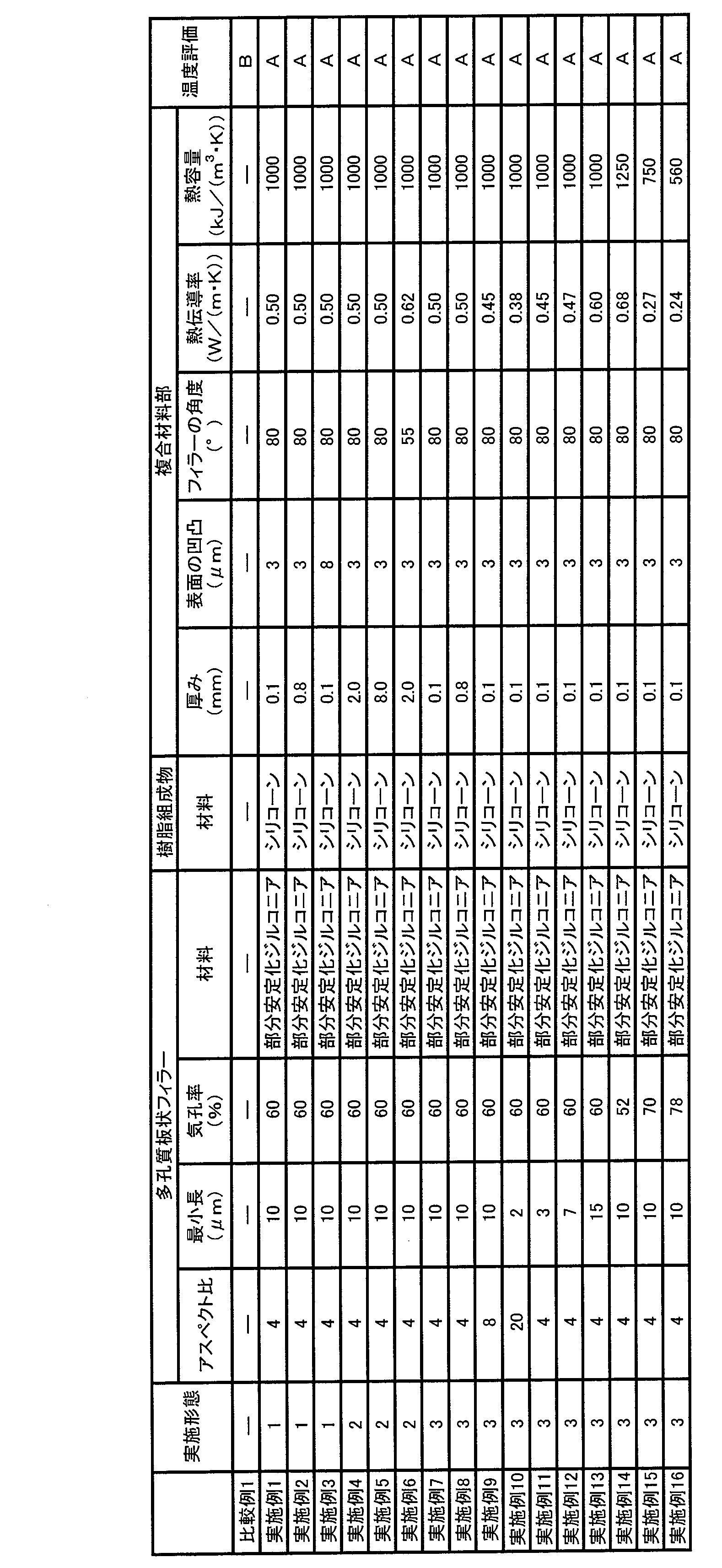
アスペクト比が3以上の板状で、その最小長が0.1~50μmであり、全体の気孔率が20~90%である多孔質板状フィラー1と、合成樹脂2と、を含む複合材料によって形成される複合材料部3を備える実施例1~16の吸気ポート18は、比較例1に比べて、管を流出した空気の温度が低かった。また、実施例7~9、11~13と実施例10を比較すると、多孔質板状フィラー1のアスペクト比が大きく、最小長が短いほど、それを含む複合材料部3の熱伝導率が低くなった。さらに、実施例14、15と実施例16を比較すると、多孔質板状フィラー1の気孔率が高いほど、それを含む複合材料部3の熱伝導率と熱容量が低くなった。
本発明の吸気ポートは自動車のエンジンに適用することができる。
1:多孔質板状フィラー、2:合成樹脂、3:複合材料部、4:金属部、6:間隙部、10:エンジン、13:シリンダヘッド、15:点火プラグ、16:吸気バルブ、17:排気バルブ、18:吸気ポート、19:排気ポート。
Claims (16)
- アスペクト比が3以上の板状で、その最小長が0.1~50μmであり、全体の気孔率が20~90%である多孔質板状フィラーと、合成樹脂と、を含む複合材料によって形成された複合材料部を備える吸気ポート。
- 前記複合材料部は、前記多孔質板状フィラーの最小長方向と吸気ポートの長手方向との角度が45°~90°である請求項1に記載の吸気ポート。
- 前記吸気ポートは前記複合材料部と、金属を含む金属部とで構成される請求項1または2に記載の吸気ポート。
- 前記吸気ポートは吸気ガス側に前記複合材料部が配置され、シリンダヘッド側に前記金属部が配置された請求項3に記載の吸気ポート。
- 前記吸気ポートの前記複合材料部は1mm以下の厚さである請求項3または4に記載の吸気ポート。
- 前記吸気ポートは前記複合材料部のみで構成される請求項1または2に記載の吸気ポート。
- 前記吸気ポートを構成する前記複合材料部の厚さが1mm以上である請求項6に記載の吸気ポート。
- 前記吸気ポートは前記複合材料部と、金属を含む金属部と、間隙部とで構成される請求項1または2に記載の吸気ポート。
- 前記吸気ポートは、吸気ガス側に前記複合材料部が配置され、シリンダヘッド側に前記金属部の二重管構造が配置された請求項8に記載の吸気ポート。
- 前記吸気ポートの前記複合材料部の厚さが1mm以下で、前記間隙部の厚さが0.1mm以上である請求項8または9に記載の吸気ポート。
- 前記複合材料部の表面の凹凸が10μm以下である請求項4~7,9,10のいずれか1項に記載の吸気ポート。
- 前記複合材料部の熱伝導率が1.5W/(m・K)以下である請求項1~11のいずれか1項に記載の吸気ポート。
- 前記複合材料部の熱容量が1500kJ/(m3・K)以下である請求項1~12のいずれか1項に記載の吸気ポート。
- 前記多孔質板状フィラーの熱伝導率が1.0W/(m・K)以下である請求項1~13のいずれか1項に記載の吸気ポート。
- 前記多孔質板状フィラーはジルコニア、部分安定化ジルコニア、完全安定化ジルコニア、酸化イットリウム、アルミナ、シリカ、チタニア、酸化ニオブ、酸化ストロンチウム、及び酸化ランタンの金属酸化物から選択される少なくとも1つを含む請求項1~14のいずれか1項に記載の吸気ポート。
- 前記合成樹脂はシリコーン、ポリイミド、ポリアミド、アクリル、及びエポキシから選択される少なくとも1つを含む請求項1~15のいずれか1項に記載の吸気ポート。
Applications Claiming Priority (4)
| Application Number | Priority Date | Filing Date | Title |
|---|---|---|---|
| US201562138431P | 2015-03-26 | 2015-03-26 | |
| US62/138,431 | 2015-03-26 | ||
| JP2015111511 | 2015-06-01 | ||
| JP2015-111511 | 2015-06-01 |
Publications (1)
| Publication Number | Publication Date |
|---|---|
| WO2016152435A1 true WO2016152435A1 (ja) | 2016-09-29 |
Family
ID=56978010
Family Applications (1)
| Application Number | Title | Priority Date | Filing Date |
|---|---|---|---|
| PCT/JP2016/056554 Ceased WO2016152435A1 (ja) | 2015-03-26 | 2016-03-03 | 吸気ポート |
Country Status (1)
| Country | Link |
|---|---|
| WO (1) | WO2016152435A1 (ja) |
Citations (3)
| Publication number | Priority date | Publication date | Assignee | Title |
|---|---|---|---|---|
| JPS52158203U (ja) * | 1976-05-26 | 1977-12-01 | ||
| JP2012072747A (ja) * | 2010-09-30 | 2012-04-12 | Mazda Motor Corp | 断熱構造体 |
| WO2013191263A1 (ja) * | 2012-06-20 | 2013-12-27 | 日本碍子株式会社 | 多孔質板状フィラー、コーティング組成物、断熱膜、および断熱膜構造 |
-
2016
- 2016-03-03 WO PCT/JP2016/056554 patent/WO2016152435A1/ja not_active Ceased
Patent Citations (3)
| Publication number | Priority date | Publication date | Assignee | Title |
|---|---|---|---|---|
| JPS52158203U (ja) * | 1976-05-26 | 1977-12-01 | ||
| JP2012072747A (ja) * | 2010-09-30 | 2012-04-12 | Mazda Motor Corp | 断熱構造体 |
| WO2013191263A1 (ja) * | 2012-06-20 | 2013-12-27 | 日本碍子株式会社 | 多孔質板状フィラー、コーティング組成物、断熱膜、および断熱膜構造 |
Similar Documents
| Publication | Publication Date | Title |
|---|---|---|
| JP6472384B2 (ja) | 断熱膜、および断熱膜構造 | |
| JP6072787B2 (ja) | 断熱用多孔質板状フィラー、コーティング組成物、断熱膜、および断熱膜構造 | |
| JP7423502B2 (ja) | 複合部材 | |
| US9284911B2 (en) | Engine combustion chamber structure, and inner wall structure of through channel | |
| US12153012B2 (en) | Gas sensor | |
| WO2015159838A1 (ja) | 多孔質板状フィラー、断熱膜、及び多孔質板状フィラーの製造方法 | |
| CN107428623A (zh) | 用于陶瓷衬底的热和环境障壁涂层 | |
| US20140352646A1 (en) | Heat-Insulating Member and Structure of Combustion Chamber for Engine | |
| JP6423360B2 (ja) | 断熱膜、および断熱膜構造 | |
| CN105764872A (zh) | 多孔材料及绝热膜 | |
| US20220252540A1 (en) | Sensor element | |
| Molin et al. | Multilayer ceramics for electrocaloric cooling applications | |
| JP4637167B2 (ja) | 測定ガスの物理的な特性を検出するセンサ素子 | |
| JP6373866B2 (ja) | 断熱膜、および断熱膜構造 | |
| WO2016152435A1 (ja) | 吸気ポート | |
| CN222144925U (zh) | 一种气体传感元件、车辆 | |
| CN110118813B (zh) | 气体传感器元件 | |
| CN115306537A (zh) | 预燃室 | |
| JP2001284668A (ja) | 積層型圧電素子及び圧電アクチュエータ並びに噴射装置 | |
| CN111279185B (zh) | 气体传感器用固体电解质、气体传感器 | |
| RU2236608C2 (ru) | Состав теплозащитного покрытия цилиндровой втулки | |
| JP7743345B2 (ja) | 排気管 | |
| EP3428136A1 (en) | High temperature thermal insulation material, particularly for gas turbine, and manufacturing method thereof | |
| WO2022014612A1 (ja) | 排気管 | |
| JP2018040717A (ja) | ガスセンサ |
Legal Events
| Date | Code | Title | Description |
|---|---|---|---|
| 121 | Ep: the epo has been informed by wipo that ep was designated in this application |
Ref document number: 16768338 Country of ref document: EP Kind code of ref document: A1 |
|
| NENP | Non-entry into the national phase |
Ref country code: DE |
|
| 122 | Ep: pct application non-entry in european phase |
Ref document number: 16768338 Country of ref document: EP Kind code of ref document: A1 |
|
| NENP | Non-entry into the national phase |
Ref country code: JP |