WO2016152144A1 - Head unit and liquid ejecting device - Google Patents
Head unit and liquid ejecting device Download PDFInfo
- Publication number
- WO2016152144A1 WO2016152144A1 PCT/JP2016/001643 JP2016001643W WO2016152144A1 WO 2016152144 A1 WO2016152144 A1 WO 2016152144A1 JP 2016001643 W JP2016001643 W JP 2016001643W WO 2016152144 A1 WO2016152144 A1 WO 2016152144A1
- Authority
- WO
- WIPO (PCT)
- Prior art keywords
- array
- block
- driver
- actuator
- actuator included
- Prior art date
- Legal status (The legal status is an assumption and is not a legal conclusion. Google has not performed a legal analysis and makes no representation as to the accuracy of the status listed.)
- Ceased
Links
Images




Classifications
-
- B—PERFORMING OPERATIONS; TRANSPORTING
- B41—PRINTING; LINING MACHINES; TYPEWRITERS; STAMPS
- B41J—TYPEWRITERS; SELECTIVE PRINTING MECHANISMS, i.e. MECHANISMS PRINTING OTHERWISE THAN FROM A FORME; CORRECTION OF TYPOGRAPHICAL ERRORS
- B41J2/00—Typewriters or selective printing mechanisms characterised by the printing or marking process for which they are designed
- B41J2/005—Typewriters or selective printing mechanisms characterised by the printing or marking process for which they are designed characterised by bringing liquid or particles selectively into contact with a printing material
- B41J2/01—Ink jet
- B41J2/015—Ink jet characterised by the jet generation process
- B41J2/04—Ink jet characterised by the jet generation process generating single droplets or particles on demand
- B41J2/045—Ink jet characterised by the jet generation process generating single droplets or particles on demand by pressure, e.g. electromechanical transducers
- B41J2/04501—Control methods or devices therefor, e.g. driver circuits, control circuits
- B41J2/04541—Specific driving circuit
-
- B—PERFORMING OPERATIONS; TRANSPORTING
- B41—PRINTING; LINING MACHINES; TYPEWRITERS; STAMPS
- B41J—TYPEWRITERS; SELECTIVE PRINTING MECHANISMS, i.e. MECHANISMS PRINTING OTHERWISE THAN FROM A FORME; CORRECTION OF TYPOGRAPHICAL ERRORS
- B41J2/00—Typewriters or selective printing mechanisms characterised by the printing or marking process for which they are designed
- B41J2/005—Typewriters or selective printing mechanisms characterised by the printing or marking process for which they are designed characterised by bringing liquid or particles selectively into contact with a printing material
- B41J2/01—Ink jet
- B41J2/015—Ink jet characterised by the jet generation process
- B41J2/04—Ink jet characterised by the jet generation process generating single droplets or particles on demand
- B41J2/045—Ink jet characterised by the jet generation process generating single droplets or particles on demand by pressure, e.g. electromechanical transducers
- B41J2/04501—Control methods or devices therefor, e.g. driver circuits, control circuits
- B41J2/04543—Block driving
-
- B—PERFORMING OPERATIONS; TRANSPORTING
- B41—PRINTING; LINING MACHINES; TYPEWRITERS; STAMPS
- B41J—TYPEWRITERS; SELECTIVE PRINTING MECHANISMS, i.e. MECHANISMS PRINTING OTHERWISE THAN FROM A FORME; CORRECTION OF TYPOGRAPHICAL ERRORS
- B41J2/00—Typewriters or selective printing mechanisms characterised by the printing or marking process for which they are designed
- B41J2/005—Typewriters or selective printing mechanisms characterised by the printing or marking process for which they are designed characterised by bringing liquid or particles selectively into contact with a printing material
- B41J2/01—Ink jet
- B41J2/015—Ink jet characterised by the jet generation process
- B41J2/04—Ink jet characterised by the jet generation process generating single droplets or particles on demand
- B41J2/045—Ink jet characterised by the jet generation process generating single droplets or particles on demand by pressure, e.g. electromechanical transducers
- B41J2/04501—Control methods or devices therefor, e.g. driver circuits, control circuits
- B41J2/04581—Control methods or devices therefor, e.g. driver circuits, control circuits controlling heads based on piezoelectric elements
-
- B—PERFORMING OPERATIONS; TRANSPORTING
- B41—PRINTING; LINING MACHINES; TYPEWRITERS; STAMPS
- B41J—TYPEWRITERS; SELECTIVE PRINTING MECHANISMS, i.e. MECHANISMS PRINTING OTHERWISE THAN FROM A FORME; CORRECTION OF TYPOGRAPHICAL ERRORS
- B41J2/00—Typewriters or selective printing mechanisms characterised by the printing or marking process for which they are designed
- B41J2/005—Typewriters or selective printing mechanisms characterised by the printing or marking process for which they are designed characterised by bringing liquid or particles selectively into contact with a printing material
- B41J2/01—Ink jet
- B41J2/015—Ink jet characterised by the jet generation process
- B41J2/04—Ink jet characterised by the jet generation process generating single droplets or particles on demand
- B41J2/045—Ink jet characterised by the jet generation process generating single droplets or particles on demand by pressure, e.g. electromechanical transducers
- B41J2/04501—Control methods or devices therefor, e.g. driver circuits, control circuits
- B41J2/04588—Control methods or devices therefor, e.g. driver circuits, control circuits using a specific waveform
-
- B—PERFORMING OPERATIONS; TRANSPORTING
- B41—PRINTING; LINING MACHINES; TYPEWRITERS; STAMPS
- B41J—TYPEWRITERS; SELECTIVE PRINTING MECHANISMS, i.e. MECHANISMS PRINTING OTHERWISE THAN FROM A FORME; CORRECTION OF TYPOGRAPHICAL ERRORS
- B41J2/00—Typewriters or selective printing mechanisms characterised by the printing or marking process for which they are designed
- B41J2/005—Typewriters or selective printing mechanisms characterised by the printing or marking process for which they are designed characterised by bringing liquid or particles selectively into contact with a printing material
- B41J2/01—Ink jet
- B41J2/015—Ink jet characterised by the jet generation process
- B41J2/04—Ink jet characterised by the jet generation process generating single droplets or particles on demand
- B41J2/045—Ink jet characterised by the jet generation process generating single droplets or particles on demand by pressure, e.g. electromechanical transducers
- B41J2/04501—Control methods or devices therefor, e.g. driver circuits, control circuits
- B41J2/04593—Dot-size modulation by changing the size of the drop
-
- B—PERFORMING OPERATIONS; TRANSPORTING
- B41—PRINTING; LINING MACHINES; TYPEWRITERS; STAMPS
- B41J—TYPEWRITERS; SELECTIVE PRINTING MECHANISMS, i.e. MECHANISMS PRINTING OTHERWISE THAN FROM A FORME; CORRECTION OF TYPOGRAPHICAL ERRORS
- B41J2/00—Typewriters or selective printing mechanisms characterised by the printing or marking process for which they are designed
- B41J2/005—Typewriters or selective printing mechanisms characterised by the printing or marking process for which they are designed characterised by bringing liquid or particles selectively into contact with a printing material
- B41J2/01—Ink jet
- B41J2/015—Ink jet characterised by the jet generation process
- B41J2/04—Ink jet characterised by the jet generation process generating single droplets or particles on demand
- B41J2/045—Ink jet characterised by the jet generation process generating single droplets or particles on demand by pressure, e.g. electromechanical transducers
- B41J2/04501—Control methods or devices therefor, e.g. driver circuits, control circuits
- B41J2/04596—Non-ejecting pulses
-
- B—PERFORMING OPERATIONS; TRANSPORTING
- B41—PRINTING; LINING MACHINES; TYPEWRITERS; STAMPS
- B41J—TYPEWRITERS; SELECTIVE PRINTING MECHANISMS, i.e. MECHANISMS PRINTING OTHERWISE THAN FROM A FORME; CORRECTION OF TYPOGRAPHICAL ERRORS
- B41J2/00—Typewriters or selective printing mechanisms characterised by the printing or marking process for which they are designed
- B41J2/005—Typewriters or selective printing mechanisms characterised by the printing or marking process for which they are designed characterised by bringing liquid or particles selectively into contact with a printing material
- B41J2/01—Ink jet
- B41J2/135—Nozzles
- B41J2/14—Structure thereof only for on-demand ink jet heads
- B41J2/14201—Structure of print heads with piezoelectric elements
-
- B—PERFORMING OPERATIONS; TRANSPORTING
- B41—PRINTING; LINING MACHINES; TYPEWRITERS; STAMPS
- B41J—TYPEWRITERS; SELECTIVE PRINTING MECHANISMS, i.e. MECHANISMS PRINTING OTHERWISE THAN FROM A FORME; CORRECTION OF TYPOGRAPHICAL ERRORS
- B41J2/00—Typewriters or selective printing mechanisms characterised by the printing or marking process for which they are designed
- B41J2/005—Typewriters or selective printing mechanisms characterised by the printing or marking process for which they are designed characterised by bringing liquid or particles selectively into contact with a printing material
- B41J2/01—Ink jet
- B41J2/135—Nozzles
- B41J2/14—Structure thereof only for on-demand ink jet heads
- B41J2/14201—Structure of print heads with piezoelectric elements
- B41J2/14233—Structure of print heads with piezoelectric elements of film type, deformed by bending and disposed on a diaphragm
-
- B—PERFORMING OPERATIONS; TRANSPORTING
- B41—PRINTING; LINING MACHINES; TYPEWRITERS; STAMPS
- B41J—TYPEWRITERS; SELECTIVE PRINTING MECHANISMS, i.e. MECHANISMS PRINTING OTHERWISE THAN FROM A FORME; CORRECTION OF TYPOGRAPHICAL ERRORS
- B41J2/00—Typewriters or selective printing mechanisms characterised by the printing or marking process for which they are designed
- B41J2/005—Typewriters or selective printing mechanisms characterised by the printing or marking process for which they are designed characterised by bringing liquid or particles selectively into contact with a printing material
- B41J2/01—Ink jet
- B41J2/135—Nozzles
- B41J2/145—Arrangement thereof
-
- B—PERFORMING OPERATIONS; TRANSPORTING
- B41—PRINTING; LINING MACHINES; TYPEWRITERS; STAMPS
- B41J—TYPEWRITERS; SELECTIVE PRINTING MECHANISMS, i.e. MECHANISMS PRINTING OTHERWISE THAN FROM A FORME; CORRECTION OF TYPOGRAPHICAL ERRORS
- B41J2/00—Typewriters or selective printing mechanisms characterised by the printing or marking process for which they are designed
- B41J2/005—Typewriters or selective printing mechanisms characterised by the printing or marking process for which they are designed characterised by bringing liquid or particles selectively into contact with a printing material
- B41J2/01—Ink jet
- B41J2/135—Nozzles
- B41J2/14—Structure thereof only for on-demand ink jet heads
- B41J2002/14491—Electrical connection
-
- B—PERFORMING OPERATIONS; TRANSPORTING
- B41—PRINTING; LINING MACHINES; TYPEWRITERS; STAMPS
- B41J—TYPEWRITERS; SELECTIVE PRINTING MECHANISMS, i.e. MECHANISMS PRINTING OTHERWISE THAN FROM A FORME; CORRECTION OF TYPOGRAPHICAL ERRORS
- B41J2202/00—Embodiments of or processes related to ink-jet or thermal heads
- B41J2202/01—Embodiments of or processes related to ink-jet heads
- B41J2202/13—Heads having an integrated circuit
Definitions
- An object of several aspects of the invention is to provide technology that solves the problems that may occur when the driver IC is mounted on the actuator substrate.
- a plurality of head units may be arranged in parallel when viewed perpendicular to the liquid ejection plane.
- the moving mechanism 6 includes a carriage motor 61 that moves the carriage 20, a carriage guide shaft 62 that is secured on each end, and a timing belt 63 that extends almost parallel to the carriage guide shaft 62, and is driven by the carriage motor 61.
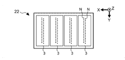
- Each of the nozzle rows Na and Nb includes a plurality of nozzles N that are arranged along the Y-direction at a pitch P1.
- the nozzle rows Na and Nb are spaced in the Y-direction by a pitch P2.
- the nozzles N that belong to the nozzle row Na and the nozzles N that belong to the nozzle row Nb are shifted in the Y-direction by half the pitch P1.
- FIG. 6 illustrates a state in which the driver IC 50 is mounted on the actuator substrate 40.
- the actuator substrate 40 is a structure in which a pressure chamber substrate 44 and a diaphragm 46 are provided on the -Z-direction-side surface of a flow channel substrate 42, and a nozzle plate 41 is provided on the +Z-direction-side surface of the flow channel substrate 42.
- the piezoelectric element Pzt includes a drive electrode 72 that is formed on the surface of the diaphragm 46 and provided common to a plurality of piezoelectric elements Pzt, a piezoelectric material 74 that is formed on the surface of the drive electrode 72, and a drive electrode 76a that is formed on the surface of the piezoelectric material 74 and provided corresponding to each piezoelectric element Pzt.
- An area in which the piezoelectric material 74 is sandwiched between the drive electrodes 72 and 76a functions as the piezoelectric element Pzt.
- the drive electrode 72 may be provided on the piezoelectric material 74, and the drive electrode 76a (76b) may be provided under the piezoelectric material 74.
- the inner volume of the cavity 442 increases (i.e., a decrease in pressure occurs), and the ink is introduced from the liquid reservoir Sr.
- the inner volume of a pressure chamber Sc decreases (i.e., an increase in pressure occurs), and an ink droplet is ejected from the nozzle N corresponding to the decrease in the inner volume of the pressure chamber Sc.
- the ink is ejected from the nozzle N due to the displacement of the piezoelectric element Pzt.
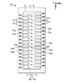
- the voltage V BS hold signal may be supplied through the line group (1) and the line group (3) as a high-voltage signal, and delivered to the center, or may be generated in the areas 570a and 570b.
- the mounting surface illustrated in FIG. 7 is designed as described below.
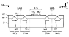
- the area 570a in which a low-voltage transistor and the like are formed
- the area 560a in which a high-voltage transistor and the like are formed
- the buffer area is a non-doped region.
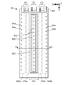
- FIG. 9 is a plan view illustrating the mounting surface of the driver IC 50 applied to a printer 1 according to the second embodiment.
- FIG. 10 is a cross-sectional view illustrating the main part of the structure of the driver IC 50 taken along the line k-k in FIG. 9.
- the wiring pattern 550 is surrounded by the wiring pattern 552 that is set to the ground potential, it is possible to reduce the effect of a change in the voltage V BS of the wiring pattern 550 on the circuits formed in the areas 570a and 570b.
Landscapes
- Particle Formation And Scattering Control In Inkjet Printers (AREA)
Abstract
Description
a structure; and
a driver IC,
the structure including a plurality of ejection sections,
the plurality of ejection sections being divided into a first array and a second array that differs from the first array, each of the plurality of ejection sections including an actuator and ejecting a liquid corresponding to a drive signal applied to one end of the actuator,
the driver IC including:
a first block that is electrically connected to one end of the actuator included in the first array, and applies the drive signal to the actuator included in the first array;
a second block that is electrically connected to one end of the actuator included in the second array, and applies the drive signal to the actuator included in the second array; and
a third block that is electrically connected to the other end of the actuator included in the first array and the other end of the actuator included in the second array, and applies a hold signal to the actuator included in the first array and the actuator included in the second array,
the driver IC being mounted on the structure so as to seal the actuator included in the first array and the actuator included in the second array, and
the third block being situated between the first block and the second block when viewed perpendicular to a mounting surface of the driver IC that is mounted on the structure.
Claims (5)
- A head unit comprising:
a structure; and
a driver IC,
the structure including a plurality of ejection sections,
the plurality of ejection sections being divided into a first array and a second array that differs from the first array, each of the plurality of ejection sections including an actuator and ejecting a liquid corresponding to a drive signal applied to one end of the actuator,
the driver IC including:
a first block that is electrically connected to one end of the actuator included in the first array, and applies the drive signal to the actuator included in the first array;
a second block that is electrically connected to one end of the actuator included in the second array, and applies the drive signal to the actuator included in the second array; and
a third block that is electrically connected to the other end of the actuator included in the first array and the other end of the actuator included in the second array, and applies a hold signal to the actuator included in the first array and the actuator included in the second array,
the driver IC being mounted on the structure so as to seal the actuator included in the first array and the actuator included in the second array, and
the third block being situated between the first block and the second block when viewed perpendicular to a mounting surface of the driver IC that is mounted on the structure. - The head unit as defined in claim 1,
the third block being formed over a non-doped region of the driver IC when viewed perpendicular to the mounting surface. - The head unit as defined in claim 1,
the third block being isolated from each of the first block and the second block through a buffer area when viewed perpendicular to the mounting surface. - The head unit as defined in claim 1,
a guard wiring section being provided between the third block and the first block and between the third block and the second block when viewed perpendicular to the mounting surface. - A liquid ejecting device comprising:
a head unit; and
a relative moving section that moves the head unit relative to a medium,
the head unit including:
a structure; and
a driver IC,
the structure including a plurality of ejection sections,
the plurality of ejection sections being divided into a first array and a second array that differs from the first array, each of the plurality of ejection sections including an actuator and ejecting a liquid by using the actuator,
the driver IC including:
a first block that is electrically connected to one end of the actuator included in the first array, and applies the drive signal to the actuator included in the first array;
a second block that is electrically connected to one end of the actuator included in the second array, and applies the drive signal to the actuator included in the second array; and
a third block that is electrically connected to the other end of the actuator included in the first array and the other end of the actuator included in the second array, and applies a hold signal to the actuator included in the first array and the actuator included in the second array,
the driver IC being mounted on the structure so as to seal the actuator included in the first array and the actuator included in the second array, and
the third block being situated between the first block and the second block when viewed perpendicular to a mounting surface of the driver IC that is mounted on the structure.
Priority Applications (4)
| Application Number | Priority Date | Filing Date | Title |
|---|---|---|---|
| CN201680017206.2A CN107428168B (en) | 2015-03-24 | 2016-03-22 | Print head unit and liquid ejection device |
| SG11201707845WA SG11201707845WA (en) | 2015-03-24 | 2016-03-22 | Head unit and liquid ejecting device |
| US15/558,375 US10195845B2 (en) | 2015-03-24 | 2016-03-22 | Head unit with driver IC and liquid ejecting device with the same |
| PH12017501737A PH12017501737A1 (en) | 2015-03-24 | 2017-09-22 | Head unit and liquid ejecting device |
Applications Claiming Priority (2)
| Application Number | Priority Date | Filing Date | Title |
|---|---|---|---|
| JP2015-060258 | 2015-03-24 | ||
| JP2015060258A JP6575097B2 (en) | 2015-03-24 | 2015-03-24 | Head unit and liquid ejection device |
Publications (1)
| Publication Number | Publication Date |
|---|---|
| WO2016152144A1 true WO2016152144A1 (en) | 2016-09-29 |
Family
ID=56978778
Family Applications (1)
| Application Number | Title | Priority Date | Filing Date |
|---|---|---|---|
| PCT/JP2016/001643 Ceased WO2016152144A1 (en) | 2015-03-24 | 2016-03-22 | Head unit and liquid ejecting device |
Country Status (7)
| Country | Link |
|---|---|
| US (1) | US10195845B2 (en) |
| JP (1) | JP6575097B2 (en) |
| CN (1) | CN107428168B (en) |
| PH (1) | PH12017501737A1 (en) |
| SG (1) | SG11201707845WA (en) |
| TW (1) | TWI675757B (en) |
| WO (1) | WO2016152144A1 (en) |
Cited By (1)
| Publication number | Priority date | Publication date | Assignee | Title |
|---|---|---|---|---|
| CN110091602A (en) * | 2018-01-31 | 2019-08-06 | 精工爱普生株式会社 | Liquid ejection apparatus |
Families Citing this family (1)
| Publication number | Priority date | Publication date | Assignee | Title |
|---|---|---|---|---|
| JP6528391B2 (en) * | 2014-11-25 | 2019-06-12 | セイコーエプソン株式会社 | Liquid discharge apparatus, head unit, integrated circuit device for driving capacitive load, and capacitive load drive circuit |
Citations (3)
| Publication number | Priority date | Publication date | Assignee | Title |
|---|---|---|---|---|
| US5889539A (en) * | 1995-07-26 | 1999-03-30 | Seiko Epson Corporation | Ink jet print head |
| JP2013159081A (en) * | 2012-02-07 | 2013-08-19 | Seiko Epson Corp | Liquid ejection apparatus |
| JP2014051008A (en) * | 2012-09-06 | 2014-03-20 | Brother Ind Ltd | Liquid jet device and piezoelectric actuator |
Family Cites Families (11)
| Publication number | Priority date | Publication date | Assignee | Title |
|---|---|---|---|---|
| JPH01112765A (en) * | 1987-10-27 | 1989-05-01 | Seiko Epson Corp | semiconductor equipment |
| JPH11345882A (en) * | 1998-05-29 | 1999-12-14 | Nec Corp | Wiring layout method of semiconductor circuit |
| TW571441B (en) * | 2002-12-31 | 2004-01-11 | Ind Tech Res Inst | Metal oxide semiconductor field effect transistor used in high-density device and manufacturing method of the same |
| EP2527152B1 (en) * | 2007-06-15 | 2013-12-11 | Zamtec Limited | printhead integrated circuit |
| JP5534740B2 (en) * | 2008-08-29 | 2014-07-02 | キヤノン株式会社 | Substrate for liquid discharge head and liquid discharge head using the same |
| JP5305018B2 (en) * | 2009-03-26 | 2013-10-02 | セイコーエプソン株式会社 | Liquid ejecting head, liquid ejecting apparatus, and actuator device |
| TWI482712B (en) * | 2009-07-27 | 2015-05-01 | 滿捷特科技公司 | Print head integrated circuit for back side electrical connection |
| JP5402760B2 (en) * | 2010-03-23 | 2014-01-29 | セイコーエプソン株式会社 | Liquid ejecting head, liquid ejecting head unit, and liquid ejecting apparatus |
| JP2012000873A (en) * | 2010-06-17 | 2012-01-05 | Seiko Epson Corp | Method for producing liquid-ejecting head |
| JP5692503B2 (en) * | 2010-09-16 | 2015-04-01 | 株式会社リコー | Inkjet head, image forming apparatus including the same, and inkjet head manufacturing method |
| JP5776214B2 (en) * | 2011-02-18 | 2015-09-09 | 株式会社リコー | Droplet discharge head and image forming apparatus |
-
2015
- 2015-03-24 JP JP2015060258A patent/JP6575097B2/en active Active
-
2016
- 2016-03-21 TW TW105108704A patent/TWI675757B/en active
- 2016-03-22 CN CN201680017206.2A patent/CN107428168B/en active Active
- 2016-03-22 US US15/558,375 patent/US10195845B2/en active Active
- 2016-03-22 WO PCT/JP2016/001643 patent/WO2016152144A1/en not_active Ceased
- 2016-03-22 SG SG11201707845WA patent/SG11201707845WA/en unknown
-
2017
- 2017-09-22 PH PH12017501737A patent/PH12017501737A1/en unknown
Patent Citations (3)
| Publication number | Priority date | Publication date | Assignee | Title |
|---|---|---|---|---|
| US5889539A (en) * | 1995-07-26 | 1999-03-30 | Seiko Epson Corporation | Ink jet print head |
| JP2013159081A (en) * | 2012-02-07 | 2013-08-19 | Seiko Epson Corp | Liquid ejection apparatus |
| JP2014051008A (en) * | 2012-09-06 | 2014-03-20 | Brother Ind Ltd | Liquid jet device and piezoelectric actuator |
Cited By (2)
| Publication number | Priority date | Publication date | Assignee | Title |
|---|---|---|---|---|
| CN110091602A (en) * | 2018-01-31 | 2019-08-06 | 精工爱普生株式会社 | Liquid ejection apparatus |
| EP3521035A1 (en) * | 2018-01-31 | 2019-08-07 | Seiko Epson Corporation | Liquid ejecting apparatus |
Also Published As
| Publication number | Publication date |
|---|---|
| PH12017501737A1 (en) | 2018-03-19 |
| US20180079203A1 (en) | 2018-03-22 |
| JP6575097B2 (en) | 2019-09-18 |
| US10195845B2 (en) | 2019-02-05 |
| CN107428168A (en) | 2017-12-01 |
| SG11201707845WA (en) | 2017-10-30 |
| CN107428168B (en) | 2019-02-01 |
| TW201641304A (en) | 2016-12-01 |
| JP2016179574A (en) | 2016-10-13 |
| TWI675757B (en) | 2019-11-01 |
Similar Documents
| Publication | Publication Date | Title |
|---|---|---|
| US10160200B2 (en) | Head unit and liquid ejecting device | |
| US8186812B2 (en) | Piezoelectric actuator, liquid transporting apparatus, and method for manufacturing piezoelectric actuator | |
| US10207496B2 (en) | Liquid jetting apparatus and wiring member | |
| US9440440B2 (en) | Liquid ejecting apparatus and liquid ejecting module | |
| US10195845B2 (en) | Head unit with driver IC and liquid ejecting device with the same | |
| JP2023094162A (en) | liquid ejection head | |
| US9216571B2 (en) | Liquid discharge apparatus and liquid discharge method | |
| JP6492844B2 (en) | Head unit and liquid ejection device | |
| JP6519259B2 (en) | Head unit and liquid discharge device | |
| US10946654B2 (en) | Liquid ejecting head, liquid ejecting apparatus, and method for setting bias potential in liquid ejecting head | |
| US9682558B2 (en) | Liquid ejection apparatus and method of formimg liquid ejection apparatus | |
| JP6488806B2 (en) | Head unit and liquid ejection device | |
| US9770902B2 (en) | Head drive IC and liquid discharge apparatus | |
| JP2019073033A (en) | Head unit and liquid discharge device | |
| JP2016179570A (en) | Head unit and liquid ejection device | |
| US20260084425A1 (en) | Liquid ejection head | |
| US20240198670A1 (en) | Head chip, liquid jet head, and liquid jet recording device | |
| US8083310B2 (en) | Liquid droplet ejecting apparatus | |
| JP2020049688A (en) | Liquid discharge device and wiring member | |
| JP2011156666A (en) | Driving apparatus for actuator | |
| JP2025176543A (en) | Droplet ejection device, control method thereof, and program | |
| JP4743195B2 (en) | Inkjet recording device | |
| JP2016144883A (en) | Liquid discharge device and head unit |
Legal Events
| Date | Code | Title | Description |
|---|---|---|---|
| 121 | Ep: the epo has been informed by wipo that ep was designated in this application |
Ref document number: 16768051 Country of ref document: EP Kind code of ref document: A1 |
|
| DPE1 | Request for preliminary examination filed after expiration of 19th month from priority date (pct application filed from 20040101) | ||
| WWE | Wipo information: entry into national phase |
Ref document number: 15558375 Country of ref document: US |
|
| WWE | Wipo information: entry into national phase |
Ref document number: 11201707845W Country of ref document: SG Ref document number: 12017501737 Country of ref document: PH |
|
| NENP | Non-entry into the national phase |
Ref country code: DE |
|
| 122 | Ep: pct application non-entry in european phase |
Ref document number: 16768051 Country of ref document: EP Kind code of ref document: A1 |