WO2016152081A1 - ネットワークシステム、ネットワーク制御方法および制御装置 - Google Patents
ネットワークシステム、ネットワーク制御方法および制御装置 Download PDFInfo
- Publication number
- WO2016152081A1 WO2016152081A1 PCT/JP2016/001433 JP2016001433W WO2016152081A1 WO 2016152081 A1 WO2016152081 A1 WO 2016152081A1 JP 2016001433 W JP2016001433 W JP 2016001433W WO 2016152081 A1 WO2016152081 A1 WO 2016152081A1
- Authority
- WO
- WIPO (PCT)
- Prior art keywords
- network
- layer
- setting
- service
- virtual
- Prior art date
Links
Images


Classifications
-
- H—ELECTRICITY
- H04—ELECTRIC COMMUNICATION TECHNIQUE
- H04L—TRANSMISSION OF DIGITAL INFORMATION, e.g. TELEGRAPHIC COMMUNICATION
- H04L45/00—Routing or path finding of packets in data switching networks
- H04L45/38—Flow based routing
-
- H—ELECTRICITY
- H04—ELECTRIC COMMUNICATION TECHNIQUE
- H04L—TRANSMISSION OF DIGITAL INFORMATION, e.g. TELEGRAPHIC COMMUNICATION
- H04L45/00—Routing or path finding of packets in data switching networks
- H04L45/74—Address processing for routing
-
- H—ELECTRICITY
- H04—ELECTRIC COMMUNICATION TECHNIQUE
- H04L—TRANSMISSION OF DIGITAL INFORMATION, e.g. TELEGRAPHIC COMMUNICATION
- H04L12/00—Data switching networks
- H04L12/28—Data switching networks characterised by path configuration, e.g. LAN [Local Area Networks] or WAN [Wide Area Networks]
- H04L12/46—Interconnection of networks
- H04L12/4641—Virtual LANs, VLANs, e.g. virtual private networks [VPN]
-
- H—ELECTRICITY
- H04—ELECTRIC COMMUNICATION TECHNIQUE
- H04L—TRANSMISSION OF DIGITAL INFORMATION, e.g. TELEGRAPHIC COMMUNICATION
- H04L45/00—Routing or path finding of packets in data switching networks
- H04L45/64—Routing or path finding of packets in data switching networks using an overlay routing layer
-
- H—ELECTRICITY
- H04—ELECTRIC COMMUNICATION TECHNIQUE
- H04L—TRANSMISSION OF DIGITAL INFORMATION, e.g. TELEGRAPHIC COMMUNICATION
- H04L47/00—Traffic control in data switching networks
- H04L47/10—Flow control; Congestion control
- H04L47/24—Traffic characterised by specific attributes, e.g. priority or QoS
- H04L47/2425—Traffic characterised by specific attributes, e.g. priority or QoS for supporting services specification, e.g. SLA
Definitions
- Non-patent Document 1 discloses a method of constructing a plurality of virtual routers on a communication node device and dynamically allocating resources of these virtual routers according to communication quality. .
- VNF Virtual Network Function
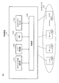
- a network service is configured and managed by a logical connection (forwarding graph) of the virtual network function VNF.
- a network service including three virtual network functions VNF # 1 to VNF # 3 is illustrated in the overlay network.
- the forwarding graph expresses a logical configuration and does not manage how it is mapped to the lower layer network.
- the service quality depends on the resource amount, state, etc. of the lower layer, it is difficult to realize quality assurance of the network service without considering the lower layer.
- the above-described patent document and non-patent document manage the arrangement of VNFs and paths between VNFs and are not involved in what kind of path is set in the lower network. Such a management using a forwarding graph cannot optimize the throughput of the entire system.
- an object of the present invention is to provide a network system, a network control method, and a control apparatus that can easily achieve quality assurance of network services and optimization of throughput of the entire system.
- a network control apparatus is an apparatus for controlling a network having a multi-layer configuration, wherein path setting means for setting a first layer path for providing a virtual network function of one network service in the first layer; Monitoring means for monitoring whether or not a network service in one layer satisfies a required service level, and changing the setting of the packet header so as to switch the first layer path at the end point of the network service according to the monitoring result Control means, and resources of the second layer lower than the first layer change according to the setting change of the packet header.
- the network control method is a method for controlling a network having a multi-layer configuration, wherein the path setting means sets a first layer path that provides a virtual network function of one network service to the first layer, and monitors the network.
- a network system includes a network having a multi-layer configuration, and a control device that controls the network, and the control device provides a virtual network function of one network service in a first layer. Set a layer path, monitor whether the network service in the first layer satisfies the required service level, and switch the first layer path at the end point of the network service according to the monitoring result.
- a program according to the present invention is a program that causes a computer to function as a device that controls a network having a multi-layer configuration, and a function of setting a first layer path that provides a virtual network function of one network service in the first layer; A function for monitoring whether or not the network service in the first layer satisfies the required service level, and changing the setting of the packet header so as to switch the first layer path at the end point of the network service according to the monitoring result And a function to realize the function to the computer.
- the quality assurance of the network service and the optimization of the throughput of the entire system can be easily achieved by changing the setting of the packet header so as to change the resource of the first layer according to the monitoring result.
- FIG. 1 is a schematic network diagram showing an example of network function virtualization.
- FIG. 2 is a schematic network diagram for explaining a schematic operation of the network system according to the first embodiment of the present invention.
- FIG. 3 is a format diagram showing an example of a packet header used in the network system according to the first embodiment.
- FIG. 4 is a block diagram showing a schematic configuration of the control device according to the first embodiment.
- FIG. 5 is a block diagram showing a schematic configuration of a node in the first embodiment.
- FIG. 6 is a block diagram showing a schematic configuration of the server in the first embodiment.
- FIG. 7 is a schematic network diagram showing an operation example of the network system shown in FIG.
- FIG. 8 is a schematic network diagram showing an operation example of the network system according to the second embodiment of the present invention.
- FIG. 1 is a schematic network diagram showing an example of network function virtualization.
- FIG. 2 is a schematic network diagram for explaining a schematic operation of the network system according to the first embodiment of the present invention.
- FIG. 9 is a schematic network diagram showing an example of a network system according to the third embodiment of the present invention.
- FIG. 10 is a schematic network diagram showing an operation example of the network system according to the third embodiment.
- FIG. 11 is a schematic network diagram showing a configuration example of a virtual layer in the network system according to the fourth embodiment of the present invention.
- FIG. 12 is a schematic network diagram showing an operation example of the network system according to the fourth embodiment.
- FIG. 13 is a schematic network diagram showing an example of a network system according to the fifth embodiment of the present invention.
- FIG. 14 is a schematic network diagram showing an example of a network system according to the sixth embodiment of the present invention.
- FIG. 15 is a sequence diagram showing the operation of the network system according to the sixth embodiment.
- FIG. 16 is a schematic network diagram showing an example of a network system according to the seventh embodiment of the present invention.
- FIG. 17 is a block diagram showing a schematic configuration of an operation management apparatus in the network system according to the seventh embodiment.
- FIG. 18 is a diagram schematically showing a display screen which is an example of network visualization by the operation management apparatus in the seventh embodiment.
- FIG. 19 is a diagram schematically showing a display screen which is an example of service chain visualization by the operation management apparatus in the seventh embodiment.
- FIG. 20 is a diagram schematically showing a display screen which is another example of service chain visualization by the operation management apparatus in the seventh embodiment.
- the resource allocation of the underlay network is indirectly changed by changing the setting of the logical component of the overlay network. For example, by changing the setting of packet encapsulation or labeling in the upper layer, all or part of the lower layer resources mapped to the logical component of the overlay network can be changed. The overall throughput can be optimized.
- each embodiment of the present invention will be described in detail.
- First Embodiment A first embodiment of the present invention will be described using a network illustrated in FIG.
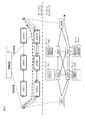
- a logical path provided with the virtual network functions VNF1 to VNF3 is formed by changing the packet header setting in the overlay network (upper layer network), and according to this, an underlay network (lower layer) as illustrated in FIG. It is assumed that a path in the layer network is formed.
- control apparatus 10 controls nodes and servers having the above-described TEP function and the like in the network 20, an overlay network setting unit 101, a node management unit 102, a database 103, and a network A monitor 104, a control unit 105, and a recording device (not shown) are included.
- the node N is a node having the above-described TEP function and the like, and includes an interface 201 for performing communication with the control apparatus 10, a path information database 202, a data transfer unit 203, and a control unit 204. .
- the node N receives data including a condition for identifying a flow belonging to the network service and a transfer destination of the packet of the flow from the control device 10 and stores the data in the route information database 202.
- the data transfer unit 203 identifies a packet of a flow belonging to the network service according to the conditions and transfer destination information stored in the route information database 202 and transfers the packet to a corresponding transfer destination (node or server).
- the packet transfer destination in the overlay network is changed by changing the setting of the packet header for the logical path, and the path in the underlay network can be changed.
- the server SV includes an interface 301 for performing communication with the control device 10, a control unit 302, a data transfer unit 303 connected to the node, a virtual machine monitor (VMM) 304, It has a virtual machine (VM) 305 and a virtual network function (VNF) 306.
- the data transfer unit 303 has a virtual switch (vSwitch) function, a TEP function, and the like. As described above, the TEP function such as encapsulation is controlled by the control device 10 through the interface 301.
- the VMM 304 controls the VM 305 and the VNF 306 is executed on the VM 305. Communication of the VM 305 is performed through the data transfer unit 303.
- control device 10 changes the packet header setting in the overlay network and the packet header is rewritten by the TEP, one is selected from a plurality of possible physical paths in the underlay network. At that time, the underlay network path selection cannot be managed from the overlay network side. In the underlay network illustrated in FIG. 2, a physical path from the switch SW1 to the SW6 through the servers SV1 and SV2 is selected.
- the virtual network functions VNF1 to VNF3 of the network service in the overlay network are provided by the physical servers SV1 and SV2 as in FIG. 2, and only the path of the underlay network to which the network service is mapped is provided. Is switched.
- the control device 10 can change the TEP setting, it can be considered that the network service does not satisfy the initial required service level.
- the TEP setting by changing the physical route mapped to the network service by changing the TEP setting described above, whether or not the performance is improved is checked. If the improvement is not improved, the TEP setting may be further changed.
- Second Embodiment According to the second embodiment of the present invention, a part of the logical configuration in the logical layer can be changed.
- the overlay network is provided with the same virtual network functions VNF1 (2) to VNF3 (2) as the virtual network functions VNF1 (1) to VNF3 (1) corresponding to the network service shown in FIG. It shall have a redundant configuration.
- the virtual network function VNF1 (1) is allocated to the physical server SV1
- the virtual network functions VNF2 (1) and VNF3 (1) are allocated to the physical server SV2, corresponding to the virtual network functions of the overlay.
- the virtual network function VNF1 (2) is arranged in the physical server SV3 and the virtual network functions VNF2 (2) and VNF3 (2) are arranged in the physical server SV4.
- the resource of the underlay network is indirectly changed accordingly.
- the control device 10 changes the TEP setting in the virtual layer of the physical server SV1 and the TEP setting in the virtual layer of the physical server SV4, thereby changing the logical resource used by the network service to the virtual network function VNF2.
- the path is switched to the path via the physical switch SW5 in the underlay network, and the virtual network function VNF1 (1) by the physical server SV1 and the virtual network functions VNF2 (2) and VNF3 (2) by the physical server SV4.
- the control device 11 when the control device 11 determines that the network service does not satisfy the required service level, the control device 11 changes the TEP setting and sets the logical resources used by the network service to FW (1) and DPI (1). And from the first logical path through NAT (1) to the second logical path through FW (2), DPI (2) and NAT (2). Accordingly, the physical switch SW1 of the underlay network switches the network service from the first path using the physical servers SV1 and SV2 to the second path using the physical servers SV3 and SV4.
- the network service including the virtual network functions VNF1 to VNF4 is illustrated, and the virtual network functions VNF3 and VNF4 can be set as redundant paths having the same function.
- the control device 11 has basically the same configuration as the control device 10 shown in FIG. 4, but the overlay network setting unit 101 includes a plurality of redundant networks having the same virtual network function in addition to the logical path setting of the first embodiment. Set the activation path.
- the network monitor 104 monitors the network status (failure or overload status), and the control unit 105 switches the logical path of the network service in accordance with the load status, that is, controls the logical resources of the overlay network, thereby providing lower resources. Indirect control.
- the control device 11 rewrites the packet header of the network service so that the logical path is switched at the end point of the network service, and thereby the logical path of the traffic is transferred to the virtual network function VNF3 (2) and VNF4 (2) side. Switch.
- the resources of the underlay network can be indirectly changed as described above.
- the logical path of the network service can be changed by rewriting the packet header (VXLAN header or the like) with TEP as described above.
- the point for changing the header setting need not be the TEP, but it is particularly desirable to change the setting at the TEP which is the end point of the network service. Since the TEP is at the entrance / exit of each VNF, the setting can be changed at each TEP.
- the virtual network functions VNF1, VNF2, VNF3, and VNF4 are a virtual load balancer (vLB), a virtual firewall (vFW), a virtual deep packet inspection (vDPI), and a virtual, respectively. It is NAT (vNAT), and vDPI and vNAT can be set with different logical paths.
- the load balancer vLB can switch all or part of the traffic to a logical path of vDPI (1) ⁇ vNAT (1) or a logical path of vDPI (2) ⁇ vNAT (2) under the control of the control device 11.
- control device 11 determines that the requested service level is not satisfied due to, for example, the occurrence of a failure or an overload condition
- the control device 11 instructs the vLB to change the packet header setting of the target network service or flow (operation S401).
- the vLB rewrites the header of the corresponding packet in accordance with an instruction from the control device 11 (operation S402), whereby all or part of the traffic is a logical path of vDPI (1) ⁇ vNAT (1) or vDPI (2) ⁇ Switch to one of the logical paths of vNAT (2).
- Such a change in the logical resources may indirectly change the resources of the underlay network so as to satisfy the required service level.
- control device 11 may determine in advance logical path candidates for a plurality of network services that pass through a virtual network function requested by a certain traffic, and select a logical path with higher performance from these candidates. It can.
- selection method any of the methods exemplified below can be adopted.
- -Select a network service that improves search performance by appropriately switching a plurality of logical path candidates. Since there are at most about 10 to 15 logical paths of the network service, it is possible to employ a method for finding the optimum solution in a search manner in this way.
- -Select a network service with higher performance in consideration of the performance of each resource in each logical path candidate. For example, the performance of resources such as a physical server, a physical switch, and a virtual machine VM is calculated, and a network service with higher performance is selected. Select a logical path candidate with the least amount of traffic at that time.
- the control device 11 selects a logical path candidate with higher performance and assigns it to the traffic. That is, similar to the above-described operation, the control device 11 instructs the vLB to change the packet header setting (operation S401), and the vLB rewrites the header of the corresponding packet according to the setting change instruction (operation S402). ).
- a network service can be provided using a logical path with better performance.
- the load balancer of an edge node is detected for the logical path of the corresponding network service in order to solve the problem.
- Change packet header settings may be part of the logical configuration as in the second embodiment described above, or may be the entire logical configuration as in the third embodiment.
- the network system includes a control device 11 and a network controlled by the control device 11, and the network includes physical switches 21A, 21B, 21C, 21D, and 21E, Of the server SV1 disposed between the switches 21A and 21C, the server SV2 disposed between the physical switches 21C and 21B, the server SV3 disposed between the physical switches 21A and 21D, and the physical switches 21D and 21E. Server SV4 arranged between them.
- the physical switch 21A is an edge switch of a network constituting a network service, and the physical switch 21A is provided with a load balancer LB physically or virtually.
- the virtual network functions VNF1 and VNF2 in this example are the physical switch 21A, the physical link, each layer component of the server SV1 (PHYSV1 / VMM1 / VM1 / VNF1), the physical link, the physical switch 21C, the physical link, and each layer component of the server SV2. (PHYSV2 / VMM2 / VM2 / VNF2) can be handled as extended network services each having a node.
- the virtual network functions VNF1 and VNF2 after the logical path switching are the physical switch 21A, physical link, each layer component of the server SV3 (PHYSV3 / VMM3 / VM1 / VNF1), physical link, physical switch 21D, physical link, server
- Each layer component (PHYSV4 / VMM4 / VM2 / VNF2) of SV4 can be handled as an extended network service having nodes as nodes.
- the control device 11 has the same configuration and function as the first embodiment shown in FIG. That is, the control unit 105 obtains monitoring information from each node of the network, stores it in the database 103, and when a problem occurs at a node where the node management unit 102 is detected, load the edge node to solve the problem. Change the packet header settings for the logical path of the network service to the balancer.
- FIG. 13 as an example, consider a case where VNF1 and VNF2 for a certain traffic are processed by the servers SV1 and SV2, respectively, and a problem such as a failure or an overload state occurs in the VNF2 and its lower nodes.
- the control device 11 monitors the network and acquires monitoring information from each node of the network (operations S501 and S502). When detecting that a problem such as a failure or an overload condition has occurred in the VNF 2 of the server SV2 and its lower layer, the control device 11 transfers all or part of the traffic to the VNF 2 node to the logical paths of the servers SV3 and SV4.
- the load balancer LB of the edge switch 21A is instructed to change the header setting of the packet (operation S503).
- the edge switch 21A at least a part of the logical paths is switched for the traffic (operation S504), and the same network service is configured through the servers SV3 and SV4.
- a packet header is set for a logical path.
- the switching of the logical path in the overlay network may be part of the logical configuration as in the second embodiment described above, or may be the entire logical configuration as in the third embodiment.
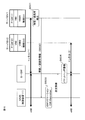
- the network system according to the sixth embodiment of the present invention is applied to a 3GPP system.
- the control device 11 described above corresponds to an MME (Mobile Management Management Entity), and is described above.
- VNF corresponds to P-GW (Packet Data Data Network Gateway). That is, as shown in the figure, the servers SV1 and SV2 generate a P-GW function in the VNF layer, and a network service including this P-GW function includes a node in each layer of P-GW / VM / VMM / PHYSV. Treated as an extended network service.
- the servers SV1 and SV2 are provided with a fault / overload state monitoring function, and the detection information of the fault / overload state is notified to the MME (control device 11).
- a user terminal UE is wirelessly connected to a base station eNB, and tunnels (GTP (GPRS (GPRS) set between the base station eNB and the S-GW (Serving Gateway) and between the S-GW and the P-GW). Packet communication can be performed with an external network (Packet Data Network) through a tunnel.
- GTP GPRS
- the control device 11 of the MME collects monitoring information from the network system and stores it in the database 103. Based on the extended network service, a problem such as a failure or an overload state is detected at a node in a certain layer. Then, it instructs the S-GW to change the tunnel.
- a problem such as a failure or an overload state occurs in the currently used P-GW (1) and the logical path of the traffic of the user terminal UE is changed will be described.
- the MME When the MME receives the failure / overload information from the server SV1, the MME refers to the database 103 and executes P-GW relocation (operation S603).
- the MME notifies the P-GW relocation setting information to the S-GW, and the S-GW rewrites the packet header of the network service with the TEP in accordance with this, so that the P-GW (1) of the server SV1 to the P- of the server SV2
- the logical path is changed to GW (2) (operation S604).
- the tunnel (2) between the S-GW and the P-GW (2) is set, and the traffic of the user terminal UE is processed by the P-GW (2).
- an operation policy is set in a control device that controls a network, and the control device executes network control similar to that of the second embodiment described above according to the operation policy.
- the operation policy for example, there is a policy of executing a predetermined control process when a load on a network or a server exceeds a predetermined value. More specifically, the control device determines whether a failure or overload condition has occurred based on the network monitoring information and the operation policy, and avoids the location of the problem when a problem occurs. Change the virtual tunnel settings to switch the logical path of the network service.
- the operation management apparatus 40 sets an operation policy for the control apparatus 12, and the control apparatus 12 performs networking according to the operation policy.
- the control device 12 has basically the same configuration and function as the control device 10 shown in FIG. 4, but is different from the fourth embodiment in that it performs policy-based control in accordance with an operation policy stored in a storage device (not shown). Is different. Since other configurations and functions are the same as those of the above-described fourth embodiment, the same reference symbols as those in FIG.
- the control device 12 may be provided in the operation management device 40.
- the control apparatus 12 sets the network based on the monitor information indicating the load status from the network and the operation policy set by the operation management apparatus 40. Take control. As described above, the control device 12 updates the database 103 by collecting monitoring information from each node of the network. When it is detected according to the operation policy that a problem such as a failure or an overload condition has occurred in a certain node, the control device 12 performs a network service to be controlled with respect to the TEP of the node upstream from the node where the problem has occurred. Alternatively, it instructs the packet header rewrite setting of the flow.
- Examples of operation policy control target parameters are as follows. -VNF, VM, VMM, and physical server availability (CPU and / or memory availability, usage, usage, power consumption, etc.). -Communication bandwidth, usage bandwidth, usage rate, traffic volume, etc. of physical links and virtual tunnels. -Network service communication bandwidth, bandwidth used, usage rate, traffic volume, etc. When these parameters exceed or fall below a predetermined threshold, the control device 12 executes the above-described packet header rewriting process for the TEP.
- the operation management device 40 includes a virtual tunnel setting unit 701, a request condition and policy setting unit 702, an interface 703, and a user interface 704.
- the user interface 704 includes an information input unit such as a keyboard and an information display unit such as a monitor. The operator makes virtual tunnel settings, request condition settings and operation policy settings, and visualization of extended network services on the network determined by the control device 12. , And so on.
- the virtual tunnel setting unit 701 generates a virtual tunnel from the network service input by the operator through the user interface 704.
- the request condition and policy setting unit 702 includes a request condition setting unit 705 and a policy setting unit 706, and generates a request condition and an operation policy for configuring a network service based on an operator input.
- the operation of the operation management apparatus 40 according to the present embodiment will be described with reference to FIGS.
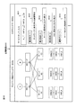
- the operation management screen 800 displayed on the user interface 704 is divided into an input window 800a and a network display window 800b.
- the input window 800a displays a network service (hereinafter referred to as a service chain) input field 801, a plurality of request condition input fields 802, and an operation policy input field 803, and the network display window 800b is an operation management target.
- the physical topology of the network and the virtual layer node are displayed.
- the operation management apparatus 40 acquires topology information and virtual layer node information from the database 103 of the control apparatus 12, and displays the physical configuration of the network and the configuration of the virtual layer based on the acquired information.
- each of the network nodes A and B is connected to the servers A, B, and C by physical links.
- Each server can arrange three virtual network functions VNF_A, VNF_B, and VNF_C, and VMs and VMMs of lower layers of each VNF are displayed as virtual layer nodes.
- VNF_A is activated on the server (A) and the same VM (B) and VNF_B are activated on the servers (B) and (C), respectively.
- the operator inputs the following service chain in the service chain input field 801 through the user interface 704: A V VNF_A ⁇ VNF_B B B. Furthermore, it is assumed that the communication bandwidth required for the network, the CPU / memory capacity required for the server and the VM are respectively input to the request condition input field 802, and the following operation policy is input to the operation policy input field 803. : “If the server CPU usage rate is greater than 80%, the service chain setting is changed or the logical path is changed.”
- the request condition and policy setting unit 702 transmits and sets the request condition and the operation policy to the control device 12.
- the control device 12 generates, for example, the following extended service chain virtual tunnels VL1, VL2, and VL3 based on the request conditions and the operation policy set by the operation management device 40, and transmits them to the operation management device 40.
- the operation management apparatus 40 displays the virtual tunnels VL1, VL2, and VL3 of the extended service chain on the network display window 800b. In this state, it is assumed that the VNF_B node is overloaded and the CPU usage rate of the server (B) exceeds 80%.
- the control device 12 detects that the CPU usage rate of the server (B) exceeds 80% based on the monitoring information from the VNF_B node, the VM (B) node, the VMM (B) node, and the physical server (B) node.
- the failure management information of the VNF_B node is notified to the operation management device 40, and the operation management device 40 displays the failure occurrence of the VNF_B node in the network display window 800b.
- the same functions as those of the virtual tunnel setting unit 701 and the request condition and policy setting unit 702 of the operation management apparatus 40 include a processor (CPU: Central Processing Unit) that executes a program, and a ROM (Read Only Memory) that stores the program, It can also be realized by a storage device such as a RAM (Random Access Memory) that holds information.
- a processor Central Processing Unit
- ROM Read Only Memory
- RAM Random Access Memory
- overlay and underlay in the above-described overlay network and underlay network are relative concepts, and may indicate not only a logical network and a physical network but also an upper logical network and a lower logical network.
- the present invention can be used in a system in which a virtual network function (VNF) is arranged on a network.
- VNF virtual network function
- Control devices VNF1 to VNF3 Virtual network functions N1 to N3 Nodes SW1 to SW5 Physical switches SV1 to SV4 Server 40 Operation management device 101 Overlay network setting unit 102 Node management unit 103 Database 104 Network monitor 105 Control unit
Landscapes
- Engineering & Computer Science (AREA)
- Computer Networks & Wireless Communication (AREA)
- Signal Processing (AREA)
- Computer Security & Cryptography (AREA)
- Data Exchanges In Wide-Area Networks (AREA)
Priority Applications (3)
| Application Number | Priority Date | Filing Date | Title |
|---|---|---|---|
| EP16767989.3A EP3276893A4 (de) | 2015-03-24 | 2016-03-14 | Netzwerksystem, netzwerksteuerungsverfahren und steuerungsvorrichtung |
| JP2017507471A JP6721869B2 (ja) | 2015-03-24 | 2016-03-14 | ネットワークシステム、ネットワーク制御方法および制御装置 |
| US15/560,811 US10511526B2 (en) | 2015-03-24 | 2016-03-14 | Network system, network control method, and control apparatus |
Applications Claiming Priority (2)
| Application Number | Priority Date | Filing Date | Title |
|---|---|---|---|
| JP2015-061747 | 2015-03-24 | ||
| JP2015061747 | 2015-03-24 |
Publications (1)
| Publication Number | Publication Date |
|---|---|
| WO2016152081A1 true WO2016152081A1 (ja) | 2016-09-29 |
Family
ID=56978207
Family Applications (1)
| Application Number | Title | Priority Date | Filing Date |
|---|---|---|---|
| PCT/JP2016/001433 WO2016152081A1 (ja) | 2015-03-24 | 2016-03-14 | ネットワークシステム、ネットワーク制御方法および制御装置 |
Country Status (4)
| Country | Link |
|---|---|
| US (1) | US10511526B2 (de) |
| EP (1) | EP3276893A4 (de) |
| JP (1) | JP6721869B2 (de) |
| WO (1) | WO2016152081A1 (de) |
Cited By (1)
| Publication number | Priority date | Publication date | Assignee | Title |
|---|---|---|---|---|
| WO2019012675A1 (ja) * | 2017-07-13 | 2019-01-17 | 株式会社日立製作所 | 管理装置及び管理方法 |
Families Citing this family (10)
| Publication number | Priority date | Publication date | Assignee | Title |
|---|---|---|---|---|
| US11570044B2 (en) * | 2016-03-15 | 2023-01-31 | Nokia Solutions And Networks Oy | Conflict resolution in network virtualization scenarios |
| US10819630B1 (en) | 2016-04-20 | 2020-10-27 | Equinix, Inc. | Layer three instances for a cloud-based services exchange |
| US10579942B2 (en) * | 2016-10-14 | 2020-03-03 | Cisco Technology, Inc. | Distributed and centralized modes for isolation networks |
| US10749841B2 (en) * | 2017-04-10 | 2020-08-18 | At&T Intellectual Property I, L.P. | Border gateway protocol multipath scaled network address translation system |
| US10965597B2 (en) * | 2017-07-01 | 2021-03-30 | Intel Corporation | Virtual network function load balancer |
| US10951317B2 (en) * | 2017-07-20 | 2021-03-16 | Huawei Technologies Canada Co., Ltd. | Multi-layer virtual network embedding |
| US10809987B2 (en) * | 2018-08-14 | 2020-10-20 | Hyperblox Inc. | Software acceleration platform for supporting decomposed, on-demand network services |
| US11588731B1 (en) | 2020-01-17 | 2023-02-21 | Equinix, Inc. | Cloud-to-cloud interface |
| WO2021186702A1 (ja) * | 2020-03-19 | 2021-09-23 | 日本電信電話株式会社 | ネットワーク管理装置、方法およびプログラム |
| US11456989B2 (en) * | 2020-03-20 | 2022-09-27 | Verizon Patent And Licensing Inc. | Systems and methods for virtualized network function (“VNF”) selection in a wireless telecommunications network |
Citations (1)
| Publication number | Priority date | Publication date | Assignee | Title |
|---|---|---|---|---|
| US20140317261A1 (en) * | 2013-04-22 | 2014-10-23 | Cisco Technology, Inc. | Defining interdependent virtualized network functions for service level orchestration |
Family Cites Families (6)
| Publication number | Priority date | Publication date | Assignee | Title |
|---|---|---|---|---|
| KR101455999B1 (ko) * | 2007-04-30 | 2014-11-03 | 엘지전자 주식회사 | 무선 통신 시스템에서의 데이터 블록 생성 방법 |
| JP5304813B2 (ja) | 2011-02-22 | 2013-10-02 | 沖電気工業株式会社 | 通信ノード装置 |
| US9787570B2 (en) | 2012-10-17 | 2017-10-10 | Verizon Patent And Licensing Inc. | Dynamic feature peer network for application flows |
| US9240944B2 (en) * | 2012-10-19 | 2016-01-19 | Cisco Technology, Inc. | Overlay services in communication networks |
| US9444675B2 (en) * | 2013-06-07 | 2016-09-13 | Cisco Technology, Inc. | Determining the operations performed along a service path/service chain |
| US10177936B2 (en) * | 2014-03-28 | 2019-01-08 | International Business Machines Corporation | Quality of service (QoS) for multi-tenant-aware overlay virtual networks |
-
2016
- 2016-03-14 EP EP16767989.3A patent/EP3276893A4/de not_active Withdrawn
- 2016-03-14 JP JP2017507471A patent/JP6721869B2/ja active Active
- 2016-03-14 US US15/560,811 patent/US10511526B2/en active Active
- 2016-03-14 WO PCT/JP2016/001433 patent/WO2016152081A1/ja active Application Filing
Patent Citations (1)
| Publication number | Priority date | Publication date | Assignee | Title |
|---|---|---|---|---|
| US20140317261A1 (en) * | 2013-04-22 | 2014-10-23 | Cisco Technology, Inc. | Defining interdependent virtualized network functions for service level orchestration |
Non-Patent Citations (3)
| Title |
|---|
| See also references of EP3276893A4 * |
| SHEN, WENYU ET AL.: "vConductor: An enabler for achieving virtual network integration as a service", IEEE COMMUNICATIONS MAGAZINE, vol. 53, no. 2, 19 February 2015 (2015-02-19), pages 116 - 124, XP032713791 * |
| YASUNOBU CHIBA ET AL.: "Study on Management and Orchestration Function to Ensure Required Service Levels in NFV Environment", IEICE TECHNICAL REPORT, vol. 113, no. 472, 27 February 2014 (2014-02-27), pages 409 - 414, XP055477040 * |
Cited By (2)
| Publication number | Priority date | Publication date | Assignee | Title |
|---|---|---|---|---|
| WO2019012675A1 (ja) * | 2017-07-13 | 2019-01-17 | 株式会社日立製作所 | 管理装置及び管理方法 |
| US11144341B2 (en) | 2017-07-13 | 2021-10-12 | Hitachi, Ltd. | Management apparatus and management method |
Also Published As
| Publication number | Publication date |
|---|---|
| JPWO2016152081A1 (ja) | 2018-01-11 |
| EP3276893A1 (de) | 2018-01-31 |
| JP6721869B2 (ja) | 2020-07-15 |
| US20180115485A1 (en) | 2018-04-26 |
| EP3276893A4 (de) | 2018-11-21 |
| US10511526B2 (en) | 2019-12-17 |
Similar Documents
| Publication | Publication Date | Title |
|---|---|---|
| JP6721869B2 (ja) | ネットワークシステム、ネットワーク制御方法および制御装置 | |
| JP6761210B2 (ja) | ネットワークシステム、ネットワーク制御方法および制御装置 | |
| WO2016157864A1 (ja) | ネットワークシステム、ネットワーク制御方法および制御装置 | |
| JP6648790B2 (ja) | ネットワークシステム、ネットワーク制御方法および制御装置 | |
| CN107078923B (zh) | 使用物理位置修改分布式虚拟网元的行为的设备和方法 | |
| EP3226495A1 (de) | Zuweisungsverfahren, vorrichtung und system für cloud-netzwerkkommunikationsweg | |
| JP6236221B2 (ja) | 管理プログラム、管理装置、およびネットワークシステム | |
| JP6436102B2 (ja) | ネットワーク管理方法および装置 | |
| US10455412B2 (en) | Method, apparatus, and system for migrating virtual network function instance | |
| US20180077048A1 (en) | Controller, control method and program | |
| US20160127232A1 (en) | Management server and method of controlling packet transfer | |
| JP5904285B2 (ja) | 通信システム、仮想ネットワーク管理装置、通信ノード、通信方法及びプログラム | |
| WO2016152080A1 (ja) | ネットワークシステム、ネットワーク制御方法、制御装置および運用管理装置 | |
| JP6292128B2 (ja) | 通信システム、ノード、制御装置、通信方法およびプログラム | |
| JP2016192661A (ja) | ネットワークシステム、ネットワーク制御方法および制御装置 | |
| EP3504845B1 (de) | Verfahren und anordnungen zur endpunktmobilität eines verkehrstechnischen tunnels eines mehrdomänen-netzwerks | |
| WO2017170310A1 (ja) | ネットワークシステムにおける管理方法および管理装置 | |
| JP2016192660A (ja) | ネットワークシステム、ネットワーク制御方法、制御装置および運用管理装置 | |
| Kataoka et al. | Orchestrating distributed mode of nfv | |
| US20180109472A1 (en) | Controller, control method and program |
Legal Events
| Date | Code | Title | Description |
|---|---|---|---|
| 121 | Ep: the epo has been informed by wipo that ep was designated in this application |
Ref document number: 16767989 Country of ref document: EP Kind code of ref document: A1 |
|
| ENP | Entry into the national phase |
Ref document number: 2017507471 Country of ref document: JP Kind code of ref document: A |
|
| WWE | Wipo information: entry into national phase |
Ref document number: 15560811 Country of ref document: US |
|
| NENP | Non-entry into the national phase |
Ref country code: DE |