WO2016151706A1 - 画像処理装置、領域決定方法及びコンピュータプログラム - Google Patents
画像処理装置、領域決定方法及びコンピュータプログラム Download PDFInfo
- Publication number
- WO2016151706A1 WO2016151706A1 PCT/JP2015/058596 JP2015058596W WO2016151706A1 WO 2016151706 A1 WO2016151706 A1 WO 2016151706A1 JP 2015058596 W JP2015058596 W JP 2015058596W WO 2016151706 A1 WO2016151706 A1 WO 2016151706A1
- Authority
- WO
- WIPO (PCT)
- Prior art keywords
- image
- rectangle
- edge pixels
- edge
- pixels
- Prior art date
- Legal status (The legal status is an assumption and is not a legal conclusion. Google has not performed a legal analysis and makes no representation as to the accuracy of the status listed.)
- Ceased
Links
Images









Classifications
-
- H—ELECTRICITY
- H04—ELECTRIC COMMUNICATION TECHNIQUE
- H04N—PICTORIAL COMMUNICATION, e.g. TELEVISION
- H04N1/00—Scanning, transmission or reproduction of documents or the like, e.g. facsimile transmission; Details thereof
- H04N1/04—Scanning arrangements, i.e. arrangements for the displacement of active reading or reproducing elements relative to the original or reproducing medium, or vice versa
-
- H—ELECTRICITY
- H04—ELECTRIC COMMUNICATION TECHNIQUE
- H04N—PICTORIAL COMMUNICATION, e.g. TELEVISION
- H04N1/00—Scanning, transmission or reproduction of documents or the like, e.g. facsimile transmission; Details thereof
- H04N1/387—Composing, repositioning or otherwise geometrically modifying originals
Definitions
- the present invention relates to an image processing apparatus, an area determination method, and a computer program, and more particularly, to an image processing apparatus, an area determination method, and a computer program for determining an area from which an image of a document should be cut out from an input image.
- a document region and other regions can be easily identified by using a monochromatic backing such as white or black.
- a scanner device of a type that reads a document placed on a desk or the like has been used, and it is necessary to accurately distinguish between a desk pattern and a document.
- a method in which a clipping mask is created for an unnecessary area (for example, a background image area) from color image data, and a necessary substantial part is clipped with the mask.
- histogram discriminant analysis is performed on each axis of the color space, and based on the analysis result, classification is performed on the axis with a high degree of separation and clustering is performed, and a cluster serving as a background portion is designated from the divided clusters. Then, a cut-out mask is created (see Patent Document 1).
- an image reading apparatus that generates reference data for document edge detection from image data of a region whose entire width is a backing portion, and detects the edge of the document by obtaining a difference between the reference data and the image data. Yes.
- This image reading apparatus detects four sides of a document by performing edge detection for only predetermined lines in the horizontal direction and the vertical direction, and automatically recognizes the document image (see Patent Document 2).
- an image processing apparatus for detecting a document boundary from an input image.
- This image processing apparatus extracts edge pixels from an input image, extracts a plurality of straight lines from the edge pixels, extracts rectangular candidates from the extracted straight lines, and extracts edge pixels within a predetermined distance from each side of each rectangular candidate.
- a rectangle is selected based on the number and the degree of angularity of each corner (see Patent Document 3).
- an image processing apparatus that determines an area in which an image of a document is to be cut out from a read image. This image processing apparatus detects a target area from the input image, detects a rectangle in the target area, and determines that the rectangle is a cut-out area when the rectangle matches the target area. The area to be included is determined as a cut-out area (see Patent Document 4).
- An image processing apparatus such as a scanner apparatus is required to detect a region where a document image is to be cut out from a read image with higher accuracy.
- the purpose of the image processing apparatus, the region determination method, and the computer program is to detect a region where a document image is to be cut out from a read image with higher accuracy.
- An image processing apparatus includes an edge pixel extraction unit that extracts edge pixels from an input image, an outer edge pixel extraction unit that extracts outer edge pixels located outside of the edge pixels, and The rectangle is detected by the rectangle detection unit that detects a rectangle from the outer edge pixels, the outer edge pixel extraction unit that extracts the outer edge edge pixels that form the outer periphery of the edge pixels to be connected among the edge pixels, and the rectangle detection unit.
- the detected rectangle is determined as an area for cutting out the image of the document from the input image, and when the rectangle is not detected by the rectangle detection unit, the outer edge pixel extracted by the outer edge pixel extraction unit is used.
- An area determination unit that determines an area including a non-rectangular rectangle as an area for cutting out an image of a document from the input image.
- the region determination method extracts edge pixels from an input image, extracts outer edge pixels located outside of the edge pixels, detects a rectangle from the outer edge pixels, An area in which outer edge edge pixels constituting the outer periphery of the edge pixels to be connected are extracted from the edge pixels, and when the rectangle is detected by the rectangle detection unit, the detected rectangle is cut out from the input image.
- a rectangle is not detected by the rectangle detection unit, a region including a non-rectangle surrounded by outer edge pixels extracted by the outer edge pixel extraction unit is cut out from the input image. Including making decisions.
- a computer program extracts edge pixels from an input image, extracts outer edge pixels located outside of the edge pixels, detects a rectangle from the outer edge pixels, and Outer edge edge pixels constituting the outer periphery of the edge pixels to be connected are extracted from the edge pixels, and when the rectangle detection unit detects the rectangle, the detected rectangle is used as an area for cutting out the image of the document from the input image.
- an area including a non-rectangle surrounded by outer edge pixels extracted by the outer edge pixel extraction unit is set as an area for cutting out a document image from the input image. Let the computer perform the decision.
- the image processing apparatus can more accurately detect a region where a document image is to be cut out from the read image.
- FIG. 1 is a diagram illustrating a schematic configuration of an image processing system 1 according to an embodiment.
- 2 is a diagram showing a schematic configuration of an image processing circuit 27.
- FIG. It is a flowchart which shows operation
- 5 is a flowchart illustrating an operation of document cutout processing. It is a flowchart which shows the example of operation
- It is a schematic diagram for demonstrating each image in a candidate area
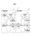
- FIG. 1 is a diagram showing a schematic configuration of an image processing system according to the embodiment.
- the image processing system 1 includes an image reading device 10 and an information processing device 20.
- the image reading device 10 is, for example, an image scanner, a digital camera, or the like
- the information processing device 20 is, for example, a personal computer that is connected to the image reading device 10 or the like.
- the image reading device 10 includes an image input device 11, a first image memory 12, a first interface device 13, a first storage device 14, and a first CPU (Control Processing Unit) 15.
- image input device 11 a first image memory 12
- first interface device 13 a first interface device 13
- first storage device 14 a first storage device 14
- first CPU Control Processing Unit
- the image input device 11 has an image sensor that images a document or the like that is an object to be imaged.
- This image sensor includes an image sensor and an optical system that forms an image of an object to be imaged on the image sensor.
- Each image sensor outputs an analog value corresponding to each color of RGB.
- the image sensor is a CCD (Charge-Coupled Device), CMOS (Complementary Metal-Oxide Semiconductor) or the like arranged in one or two dimensions.
- the image input device 11 converts each analog value output from the imaging sensor into a digital value to generate pixel data, and generates image data (hereinafter referred to as an RGB image) composed of the generated pixel data.
- the RGB image is color image data in which each pixel data is composed of a total of 24 bits of RGB values represented by 8 bits for each RGB color, for example.
- the image input device 11 generates an image (hereinafter referred to as a read image) obtained by converting an RGB image or an RGB value of each pixel of the RGB image into a luminance value and a color difference value (YUV value), and stores the image in the first image memory 12. To do.
- the first image memory 12 has a storage device such as a nonvolatile semiconductor memory, a volatile semiconductor memory, and a magnetic disk.
- the first image memory 12 is connected to the image input device 11 and stores a read image generated by the image input device 11.
- the first interface device 13 has an interface circuit conforming to a serial bus such as USB (Universal Serial Bus), and is electrically connected to the information processing device 20 to transmit and receive image data and various types of information.
- a flash memory or the like may be connected to the first interface device 13 to temporarily store the image data stored in the first image memory 12 and copy it to the information processing device 20.
- the first storage device 14 includes a memory device such as a RAM (Random Access Memory) and a ROM (Read Only Memory), a fixed disk device such as a hard disk, or a portable storage device such as a flexible disk and an optical disk. Further, the first storage device 14 stores computer programs, databases, tables, and the like used for various processes of the image reading device 10.
- the computer program may be installed in the first storage device 14 using a known setup program or the like from a computer-readable portable recording medium.
- the portable recording medium is, for example, a CD-ROM (compact disk read only memory) or a DVD-ROM (digital versatile disk read only memory).
- the first CPU 15 is connected to the image input device 11, the first image memory 12, the first interface device 13, and the first storage device 14, and controls these units.
- the first CPU 15 performs read image generation control of the image input device 11, control of the first image memory 12, data transmission / reception control with the information processing device 20 via the first interface device 13, control of the first storage device 14, and the like. .
- the information processing apparatus 20 includes a second interface device 21, a second image memory 22, a display device 23, an input device 24, a second storage device 25, a second CPU 26, and an image processing circuit 27.
- a second interface device 21 a second image memory 22
- a display device 23 an input device 24
- a second storage device 25 a second CPU 26
- an image processing circuit 27 an image processing circuit 27
- the second interface device 21 has an interface circuit similar to the first interface device 13 of the image reading device 10 and connects the information processing device 20 and the image reading device 10.
- the second image memory 22 has a storage device similar to the first image memory 12 of the image reading device 10.
- the second image memory 22 stores the read image received from the image reading device 10 via the second interface device 21 and is connected to the image processing circuit 27.
- the image processing circuit 27 performs image processing on the read image. Save the various processed images.
- the display device 23 includes a display composed of liquid crystal, organic EL, and the like, and an interface circuit that outputs image data to the display, and is connected to the second image memory 22 and stored in the second image memory 22. Appears on the display.
- the input device 24 has an input device such as a keyboard and a mouse, and an interface circuit that acquires signals from the input device, and outputs a signal corresponding to a user operation to the second CPU 26.
- the second storage device 25 includes a memory device, a fixed disk device, a portable storage device, and the like similar to the first storage device 14 of the image reading device 10.
- the second storage device 25 stores computer programs, databases, tables, and the like used for various processes of the information processing device 20.
- the computer program may be installed in the second storage device 25 from a computer-readable portable recording medium such as a CD-ROM or DVD-ROM using a known setup program or the like.
- the second CPU 26 is connected to the second interface device 21, the second image memory 22, the display device 23, the input device 24, the second storage device 25 and the image processing circuit 27, and controls these parts.
- the second CPU 26 performs data transmission / reception control with the image reading device 10 via the second interface device 21, control of the second image memory 22, display control of the display device 23, input control of the input device 24, and control of the second storage device 25. Control, image processing control by the image processing circuit 27, and the like are performed.
- the image processing circuit 27 is connected to the second image memory 22 and performs a document cutting process.
- the image processing circuit 27 is connected to the second CPU 26 and operates based on a program stored in advance in the second storage device 25 under the control of the second CPU 26.
- the image processing circuit 27 may be configured by an independent integrated circuit, a microprocessor, firmware, and the like.
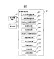
- FIG. 2 is a diagram showing a schematic configuration of the image processing circuit 27.
- the image processing circuit 27 includes an edge pixel extraction unit 201, a candidate area detection unit 202, an outer edge pixel extraction unit 203, a straight line detection unit 204, a rectangular detection unit 205, an outer edge pixel extraction unit 206, a non-rectangular shape.
- a detection unit 207, a mask generation unit 208, an area determination unit 209, a cutout unit 210, and a storage control unit 211 are included.
- Each of these units is a functional module implemented by software operating on the processor.
- Each of these units may be composed of an independent integrated circuit, a microprocessor, firmware, and the like.
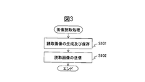
- FIG. 3 is a flowchart showing the operation of the image reading process by the image reading apparatus 10. The operation of the image reading process will be described below with reference to the flowchart shown in FIG. The operation flow described below is executed mainly by the first CPU 15 in cooperation with each element of the image reading device 10 based on a program stored in advance in the first storage device 14.
- the image input device 11 generates a read image obtained by photographing a document that is an object to be imaged, and stores it in the first image memory 12 (step S101).
- the first CPU 15 transmits the read image stored in the first image memory 12 to the information processing apparatus 20 via the first interface device 13 (step S102), and ends a series of steps.
- FIG. 4 is a flowchart showing the operation of the document cutting process performed by the information processing apparatus 20.
- the operation of the document cutting process will be described with reference to the flowchart shown in FIG.
- the operation flow described below is mainly executed by the second CPU 26 in cooperation with each element of the information processing device 20 based on a program stored in the second storage device 25 in advance.
- the second CPU 26 acquires a read image from the image reading device 10 via the second interface device 21 and stores it in the second image memory 22 (step S201).
- the image processing circuit 27 reads the read image stored in the second image memory 22, generates a first input image in which pixels are thinned out in the horizontal direction and the vertical direction for the read image, and stores them in the second image memory 22. Save (step S202).
- the first input image is an example of an input image.
- the ratio of thinning out pixels is determined according to the processing capability of the second CPU 26 and the like and the processing speed required for the information processing apparatus 20. If the required processing speed is satisfied without thinning out pixels, the read image may be used as it is as the first input image.
- each part of the image processing circuit 27 performs a cut-out area determination process for the first input image (step S203), and ends a series of steps.
- each unit of the image processing circuit 27 determines a cut-out area from which a document image is cut out from the first input image. Details of the cut-out area determination process will be described later.
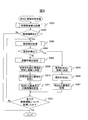
- FIG. 5 is a flowchart showing an example of the operation of the cut-out area determination process. The operation flow shown in FIG. 5 is executed in step S203 of the flowchart shown in FIG.
- the edge pixel extraction unit 201 and the candidate region detection unit 202 perform a candidate region detection process on the first input image (step S301).
- the edge pixel extraction unit 201 extracts edge pixels from the first input image
- the candidate area detection unit 202 detects a candidate area surrounded by connected edge pixels among the extracted edge pixels. . Details of the candidate area detection processing will be described later.
- the candidate area detection unit 202 determines whether or not a candidate area has been detected in the candidate area detection process (step S302). If no candidate area is detected, the candidate area detection unit 202 ends the series of steps without performing any particular process. On the other hand, if the candidate area is detected, the process proceeds to step S303. The processes in steps S303 to S315 are performed for each extracted candidate area.
- the edge pixel extraction unit 201, the outer edge pixel extraction unit 203, the straight line detection unit 204, and the rectangle detection unit 205 perform a rectangle detection process on the candidate area (step S303).
- the edge pixel extraction unit 201 extracts edge pixels
- the outer edge pixel extraction unit 203 extracts outer edge pixels located outside of the edge pixels.
- the straight line detection unit 204 detects a plurality of straight lines from the outer edge pixels
- the rectangular detection unit 205 detects a rectangle composed of four straight lines in which two of the detected straight lines are approximately orthogonal to each other. To detect. Details of the rectangle detection process will be described later.
- the area determination unit 209 determines whether or not a rectangle is detected by the rectangle detection unit 205 in the rectangle detection process (step S304).
- the region determination unit 209 determines the detected rectangle as a cut-out region for cutting out an original image from the first input image (step S305).
- the cutout unit 210 cuts out the determined cutout region, that is, the detected rectangle from the input image (step S306).
- the storage control unit 211 stores the cut image in the second image memory 22 (step S307).
- the storage control unit 211 stores the clipped image in a storage medium that stores the image for a long time, such as a nonvolatile semiconductor memory, in the second image memory 22.
- the storage control unit 211 may store the clipped image in a hard disk or the like of the second storage device 25.
- the image stored in the second image memory 22 or the second storage device 25 is displayed on the display device 23 in accordance with a request from the user using the input device 24.
- the edge pixel extraction unit 201, the outer peripheral edge pixel extraction unit 206, the non-rectangular detection unit 207, and the mask generation unit 208 perform non-rectangular detection processing on the candidate area when the rectangle detection unit 205 does not detect a rectangle.
- the edge pixel extraction unit 201 extracts edge pixels
- the outer edge pixel extraction unit 206 extracts outer edge pixels that form the outer periphery of the edge pixels to be connected among the extracted edge pixels.
- the non-rectangular detection unit 207 detects a non-rectangular shape surrounded by outer edge pixels, and the mask generation unit 208 generates a mask for separating the background from the image to be cut based on the detected non-rectangular shape. To do. Details of the non-rectangular detection process will be described later.
- the area determining unit 209 determines an area including the non-rectangle detected in the non-rectangular detection process as a cut-out area for cutting out the document image from the first input image (step S309).
- the area determining unit 209 determines the detected non-rectangular circumscribed rectangle as a cut-out area.
- the region determination unit 209 may determine the detected non-rectangle itself as a cutout region.
- the cutout unit 210 cuts out a region including the determined cutout region from the first input image (step S310). Further, the cutout unit 210 uses the mask generated by the mask generation unit 208 to extract a separated image that represents only the original, with the background separated from the cutout image.
- the storage control unit 211 stores the cut image and the separated image in the second image memory 22 (step S311).
- the storage control unit 211 stores the cut-out image in a storage medium that stores the image for a long time, such as a nonvolatile semiconductor memory, in the second image memory 22, and stores the separated image in an image such as a volatile semiconductor memory. Is stored in a storage medium that temporarily stores.
- the storage control unit 211 may store the cut image in a hard disk or the like of the second storage device 25 and store the separated image in the RAM.
- the storage control unit 211 stores the cut image as a file, and stores the separated image so as to be usable by a specific application by storing the separated image on a clipboard, for example.
- the user can use the separated image by executing only the pasting command in the document editing software, the image editing software, the spreadsheet software, etc., and the convenience of the user can be improved. It becomes possible.
- the storage control unit 211 may change the file format for saving the image (and the separated image) cut out when a rectangle is detected and when a non-rectangle is detected. For example, when the rectangle is detected (in the case of step S307), the storage control unit 211 saves the clipped image in a JPEG (Joint Photographic Experts Group) format. On the other hand, when the storage control unit 211 detects a non-rectangular shape (in the case of step S311), the storage control unit 211 stores the clipped image in a transparent PNG (Portable Network Graphics) format. As a result, the information processing apparatus 20 can store the image in a format suitable for the shape, and can improve the convenience for the user.
- JPEG Joint Photographic Experts Group
- the image processing circuit 27 determines whether or not all candidate areas have been processed (step S312). If there is a candidate area that has not yet been processed, the image processing circuit 27 returns the process to step S303 and repeats the processes of steps S303 to S312. If all candidate areas have been processed, the series of steps ends.
- FIG. 6 is a flowchart showing an example of operation of candidate area detection processing. The operation flow shown in FIG. 6 is executed in step S301 of the flowchart shown in FIG.
- the edge pixel extraction unit 201 generates a second input image obtained by further thinning pixels in the horizontal direction and the vertical direction from the first input image, and stores the second input image in the second image memory 22 (step S401).
- the second input image is another example of the input image.
- An image 700 illustrated in FIG. 7A is an example of a first input image.
- the first input image 700 is an image obtained by taking a book 701 placed on a desk having a pattern 702 such as a woodgrain as a document.
- An image 710 illustrated in FIG. 7B is an example of a second input image.
- the thinning rate from the first input image 700 to the second input image 710 eliminates random noise 703 caused by the influence of the image pickup device and the optical system of the image input device 11 of the image reading device 10.
- the portion 704, the character 705, etc. are predetermined so as not to be removed.
- edge pixel extraction unit 201 may remove the random noise 703 by applying a smoothing filter to the first input image instead of generating the second input image.
- the edge pixel extraction unit 201 may further apply a smoothing filter to the second input image.
- the edge pixel extraction unit 201 extracts edge pixels in the horizontal direction and the vertical direction from the second input image.
- the edge pixel extraction unit 201 generates an edge image including pixels extracted as edge pixels in either the horizontal direction or the vertical direction of the second input image, and stores the edge image in the second image memory 22 (step S402).
- the edge pixel extraction unit 201 calculates an absolute value (hereinafter referred to as an adjacent difference value) of luminance values of pixels adjacent to each other in the horizontal direction of each pixel of the second input image, and the adjacent difference value exceeds the threshold value Th1.
- the pixel on the image is a vertical edge pixel.
- This threshold value Th1 can be set, for example, to a luminance value difference (for example, 20) that allows a person to visually distinguish the luminance difference on the image.
- the edge pixel extraction unit 201 performs the same processing in the vertical direction for each image to extract horizontal edge pixels.
- the edge pixel extraction unit 201 may calculate the variance value of the pixel of interest and the pixel adjacent to the pixel of interest in the horizontal direction, vertical direction, and diagonal direction (near 8) as the variance value for the pixel of interest. In that case, the edge pixel extraction unit 201 may extract the vertical edge pixel and the horizontal edge pixel from the adjacent difference value for the variance value of each pixel.
- the edge pixel extraction unit 201 groups the extracted vertical edge pixels and horizontal edge pixels by labeling, and removes edge pixels included in a group whose horizontal size or vertical size is equal to or smaller than a threshold value Th2. May be.
- the threshold value Th2 is set to a value (for example, a value corresponding to 3 mm) that is assumed as dirt on the document placement surface. Further, the edge pixel extraction unit 201 may remove edge pixels included in a group when the area of each group or the area of a circumscribed rectangle of each group is equal to or smaller than a threshold value. As a result, it is possible to remove edge pixels caused by contamination of the document placement surface.
- the edge pixel extraction unit 201 generates an image composed of pixels extracted as vertical edge pixels or horizontal edge pixels in the second input image as an edge image. Note that the edge pixel extraction unit 201 may perform expansion / contraction processing on the generated edge image. Thereby, even when a part of the connected part in the second input image is not extracted as an edge pixel, the part can be connected in the edge image.
- the candidate area detection unit 202 determines whether or not each edge pixel is connected to other edge pixels in the edge image, and labels the connected edge pixels as one group (step S403). .
- the candidate area detection unit 202 determines that edge pixels adjacent to each other in the horizontal direction, the vertical direction, or the oblique direction (near 8) are connected.
- the edge pixel extraction unit 201 may determine that edge pixels adjacent to each other are connected only in the horizontal direction or the vertical direction (near 4).
- the candidate area detection unit 202 determines whether both the horizontal and vertical sizes of each group are equal to or smaller than a threshold Th3, and both the horizontal and vertical sizes are equal to or smaller than the threshold Th3. Edge pixels included in the group are removed from the edge image (step S404).
- the threshold value Th3 is set to the minimum document size (for example, a value corresponding to 1 inch) for which the information processing device 40 guarantees detection.
- the candidate area detection unit 202 has a case where the size of each group in the horizontal direction and the vertical direction is equal to or smaller than the threshold value Th3, or the area of each group or the area of the circumscribed rectangle of each group is equal to or smaller than the threshold value.
- edge pixels may be removed.
- the threshold value to be compared with the area of the circumscribed rectangle can be set to a value corresponding to 1 inch square, for example.
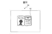
- An image 720 shown in FIG. 7C is an example of an edge image from which edge pixels included in a group having a predetermined size or less are removed.
- the image 720 like the desk pattern 711 shown in FIG. 7B, a group of edge pixels smaller than the minimum size of the document that the information processing device 40 guarantees detection is removed.
- the candidate area detection unit 202 determines whether or not each group is included in another group, and removes edge pixels included in the group included in the other group from the edge image (step S405).
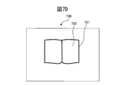
- An image 730 illustrated in FIG. 7D is an example of an edge image in which edge pixels included in a group included in another group are removed.
- the image 730 as in the content 721 shown in FIG. 7C, a group of edge pixels due to the content in the document is removed.
- the candidate area detection unit 202 detects, for each group remaining without being removed, an area surrounded by edge pixels included in the group, and candidates for the area in the first input image corresponding to the detected area are detected. Detect as a region.
- the candidate area detection unit 202 stores the circumscribed rectangle of the candidate area in the first input image in the second image memory 22 (step S406), and ends a series of steps.
- the region surrounded by the connected edge pixels is the outermost outer periphery 731 and the inner region of the group of connected edge pixels, and the region includes not only the edge pixels but also the outer periphery. All the pixels 732 existing inside 731 are included.
- the region surrounded by the connected edge pixels may be a region that does not include the outermost outer periphery of the group of connected edge pixels.
- the region surrounded by the connected edge pixels may be a region obtained by expanding or contracting the outermost outer periphery of the group of connected edge pixels and the inner region by a predetermined pixel.
- the edge pixels to be connected by performing expansion / contraction processing on the edge image as described above, not only the edge pixels adjacent to each other, but also the edge pixels located within a predetermined distance from each other and between them Pixels located may be included.
- the pixels located between the edge pixels at both ends may be included in the edge pixels to be connected.
- the predetermined distance can be a length obtained by multiplying the length of edge pixels to be connected by a predetermined ratio (for example, 80%).
- FIG. 8 is a flowchart showing an example of the operation of the rectangle detection process. The operation flow shown in FIG. 8 is executed in step S303 of the flowchart shown in FIG.
- the edge pixel extraction unit 201 extracts vertical edge pixels and horizontal edge pixels in the candidate area detected by the candidate area detection unit 202, and outputs an image including pixels extracted as vertical edge pixels or horizontal edge pixels.
- a two-edge image is generated (step S501).
- the edge pixel extraction unit 201 extracts vertical edge pixels and horizontal edge pixels in the same manner as when an edge image is generated. Note that the edge pixel extraction unit 201 may extract the vertical edge pixel and the horizontal edge pixel from the second input image, as in the case where the edge image is generated. Further, the edge pixel extraction unit 201 may group the extracted vertical edge pixels and horizontal edge pixels by labeling, and remove edge pixels included in a group whose size is equal to or smaller than the threshold value Th2.
- the edge pixel extraction unit 201 may extract the vertical edge pixel and the horizontal edge pixel by other methods. For example, the edge pixel extraction unit 201 generates a plurality of thinned images obtained by thinning pixels from the first input image at different thinning rates, and extracts vertical edge pixels from the first input image and the thinned images, respectively. An edge image composed of pixels is generated. The edge pixel extraction unit 201 enlarges the edge image generated from the smallest thinned image to the same resolution as the edge image generated from the next smallest thinned image, and at the same position in the two edge images having the same resolution. An image composed of existing vertical edge pixels is generated.
- the edge pixel extraction unit 201 repeats the same processing on the generated image and the edge image generated from the next smaller thinned image, and finally the vertical edge pixel of the edge image generated from the first input image Extract vertical edge pixels at the same position. Further, the edge pixel extraction unit 201 extracts horizontal edge pixels by the same process. Thereby, vertical edge pixels and horizontal edge pixels can be extracted while reducing noise.
- edge pixel extraction unit 201 does not perform expansion / contraction processing on the generated second edge image. Thereby, in the 2nd edge picture, it is prevented that the pattern of a desk, noise, etc. are connected accidentally.
- the outer edge pixel extraction unit 203 determines whether or not the end of the candidate area is close to the end of the first input image (step S502).
- the outer edge pixel extraction unit 203 determines that the candidate area is close when any of the left edge, right edge, upper edge, and lower edge of the candidate area is within a predetermined distance from the left edge, right edge, upper edge, or lower edge of the first input image. If it is not within the predetermined distance, it is determined that it is not close.
- the predetermined distance is determined to be the maximum distance from the end of the first input image where an edge pixel may not be extracted even though an object shown in the candidate area intersects the end of the first input image. For example, it is set to a distance corresponding to 10 mm.
- the outer edge pixel extraction unit 203 determines that the end of the candidate area is the end of the first input image when the candidate area protrudes beyond the predetermined document reading range in the first input image. You may determine with approaching, and you may determine with not approaching, when it is settled. In this case, the user can recognize the document reading range by shooting the document after placing a mat indicating the document reading range on the desk on which the document is placed. Note that the image reading apparatus 10 may cause the user to recognize the document reading range by irradiating light indicating the document reading range from a light irradiation unit (not shown) to a desk on which the document is placed.
- the outer edge pixel extraction unit 203 extracts an outer edge pixel located outside of the extracted edge pixels when the edge of the candidate area is not close to the edge of the first input image.
- the outer edge pixel extraction unit 203 generates an image composed of pixels extracted as outer edge pixels as a third edge image (step S503).
- FIG. 9A and FIG. 9B are schematic diagrams for explaining the outer edge pixel extraction processing.
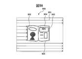
- An image 900 shown in FIG. 9A is an example of a second edge image.
- the outer edge pixel extraction unit 203 scans each horizontal line of the second edge image 900 from the left end side to the right end side as indicated by an arrow 901, and the edge pixel 902 detected first is set to the outer side. Extract as edge pixels.
- the outer edge pixel extraction unit 203 scans each horizontal line of the second edge image 900 from the right end side toward the left end side, and extracts the edge pixel 903 detected first as the outer edge pixel.
- the outer edge pixel extraction unit 203 scans each vertical line of the second edge image 900 from the upper end side to the lower end side and from the lower end side to the upper end side, and the edge pixels 904 and 905 detected first are also detected. Extracted as outer edge pixels. That is, the outer edge pixel extraction unit 203 is located at the leftmost edge and the rightmost edge pixel in each horizontal line in the candidate area, and the uppermost edge and the lower edge side in each vertical line in the candidate area. Edge pixels are extracted as outer edge pixels.
- the outer edge pixel 911 includes edge pixels 902 to 905 detected from the second edge image 900 of FIG. 9A.
- the outer edge pixel extraction unit 203 when the edge of the candidate area is close to the edge of the first input image, the outer edge pixel extraction unit 203 generates an image composed of all edge pixels in the candidate area as a third edge image (Ste S504). In this case, in the rectangle processing described later, the rectangle detection unit 205 detects a rectangle from all the edge pixels in the candidate area.
- FIGS. 10A and 10B are schematic diagrams for explaining an example in which the end of the candidate area is close to the end of the first input image.
- An image 1000 shown in FIG. 10A shows a state where the document 1001 is held by the user's hands 1002 and 1003.
- the edge pixels by the user's hands 1002 and 1003 protrude beyond the document reading range 1004 and are located up to the end of the first input image.
- An image 1010 illustrated in FIG. 10B is an example of an outer edge pixel extracted from the image 1000 illustrated in FIG. 10A.
- document edges 1005 and 1006 located inside the user's hands 1002 and 1003 are not extracted as outer edge pixels 1011. In such a case, it is possible to prevent the edge of the document from being extracted by generating an image including all edge pixels in the candidate area as the third edge image.
- the outer edge pixel extraction unit 203 may remove some edge pixels in the candidate area from the third edge image when the end of the candidate area is close to the end of the first input image. .
- the outer edge pixel extraction unit 203 detects a straight line in the vertical direction within the candidate area, and the edge of the candidate area Is close to the vertical end of the first input image, a horizontal straight line is detected in the candidate region.
- the outer edge pixel extraction unit 203 removes edge pixels between the two outermost detected straight lines from the third edge image. As a result, the content in the document can be removed from the detection target of the edge of the document, and the detection accuracy of the edge of the document can be improved.
- the straight line detection unit 204 detects a plurality of straight lines from the third edge image (step S505).
- the straight line detection unit 204 detects a straight line using the Hough transform.
- the straight line detection unit 204 may detect a straight line using a least square method.
- the straight line detection unit 204 may detect a straight line using the least square method for edge pixels within a predetermined distance from the straight line detected using the Hough transform. This predetermined distance is appropriately determined according to the environment where the image processing system 1 is used, and is set to a distance corresponding to 2 mm, for example.
- the straight line detection unit 204 detects an approximate straight line from the third edge image (step S506).
- FIG. 11A and FIG. 11B are schematic diagrams for explaining the approximate straight line.
- a first input image 1100 obtained by photographing a book document as shown in FIG. 11A an end 1102 parallel to the binding portion 1101 of the book document is detected as a straight line.
- the end 1103 orthogonal to the stitch part 1101 may be distorted in the vicinity of the stitch part 1101, and may not be detected as a straight line.
- the straight line detection unit 204 collects edge pixels 1111 adjacent to each other into one group 1112 by labeling.
- the straight line detection unit 204 detects a straight line 1115 connecting the edge pixels 1113 and the edge pixels 1114 located at both ends in the horizontal direction or the vertical direction among the edge pixels included in the group 1112 as an approximate straight line.
- the rectangle detection unit 205 detects a rectangle formed by the straight line or the approximate line detected by the straight line detection unit 204 (step S507), and ends a series of steps.
- the rectangle detection unit 205 extracts a plurality of rectangle candidates that are composed of four straight lines in which two of the plurality of straight lines or approximate straight lines detected by the straight line detection unit 204 are approximately orthogonal to each other.
- the rectangle detection unit 205 first selects one horizontal straight line (hereinafter referred to as a first horizontal line), and is substantially parallel to the selected straight line (for example, within ⁇ 3 °) and is a horizontal straight line separated by a threshold Th4 or more. (Hereinafter referred to as the second horizontal line).
- the rectangle detection unit 205 extracts a straight line (hereinafter referred to as a first vertical line) in the vertical direction substantially orthogonal to the first horizontal line (for example, within ⁇ 3 ° with respect to 90 °).
- the rectangle detection unit 205 extracts a straight line (hereinafter referred to as a second vertical line) that is substantially perpendicular to the first horizontal line and that is separated from the first vertical line by a threshold Th5 or more.
- a straight line hereinafter referred to as a second vertical line
- Th5 a straight line that is substantially perpendicular to the first horizontal line and that is separated from the first vertical line by a threshold Th5 or more.
- the threshold value Th4 and the threshold value Th5 are determined in advance according to the size of the document to be read by the image reading apparatus 10, and may be the same value.
- the rectangle detection unit 205 includes all of the first horizontal line, the second horizontal line, the first vertical line, and the second vertical line that satisfy the above conditions for all the straight lines or approximate straight lines detected by the straight line detection unit 204.
- a combination is extracted, and a rectangle composed of each extracted combination is extracted as a rectangle candidate.
- the rectangle detection unit 205 calculates an area for the extracted rectangle candidates, and removes rectangle candidates whose area is less than a predetermined value.
- the rectangle detection unit 205 detects a rectangle candidate having the largest area among the remaining rectangle candidates as a rectangle. On the other hand, the rectangle detection unit 205 does not detect a rectangle when no rectangle candidate remains.
- the rectangle detection unit 205 calculates the ratio of the number of edge pixels within a predetermined distance to the number of all pixels within a predetermined distance (for example, a distance corresponding to 2 mm) from each side of the rectangle candidate for each rectangle candidate. It may be calculated and weighted by multiplying the area of the rectangular candidate by the ratio. This makes it possible to detect a rectangle composed of straight lines that clearly represent the document boundary. Alternatively, the rectangle detection unit 205 may calculate an evaluation point indicating the degree of angularity of each corner of the rectangle candidate for each rectangle candidate, and weight the area of the rectangle candidate using the evaluation point.
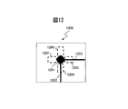
- FIG. 12 is a schematic diagram for explaining evaluation points at each corner of a rectangle candidate.
- a point 1201 represents a corner of a rectangle candidate
- straight lines 1202 and 1203 represent sides of the rectangle candidate.
- the point 1201 is considered to be a rectangular corner.
- the ends of the straight lines 1202 and 1203 are not in contact with each other, or the straight lines 1202 and 1203 intersect. If so, the point 1201 is not considered to be a rectangular corner.
- ⁇ ⁇ Evaluation points are based on 0 points. Then, in an area 1204 within a predetermined distance from the side 1202 in the vicinity of the corner 1201, it is determined whether or not an edge pixel exists for each horizontal line. Add one point to.
- the range in the vicinity of each corner and the predetermined distance from each side are appropriately determined according to the environment or the like in which the image processing system 1 is used. For example, the range within a distance corresponding to 5 mm from each corner and each side A distance corresponding to 2 mm can be set.
- in an area 1205 within a predetermined distance from the side 1203 in the vicinity of the corner 1201 it is determined whether or not there is an edge pixel for each vertical line, and evaluation is performed when there is an edge pixel in the vertical line.
- the rectangle detection unit 205 calculates a value obtained by normalizing the evaluation points so that the lowest possible value of the evaluation point is 0 and the highest possible value is 1, and weights the area of the rectangular candidate by multiplying the value. Thus, a rectangle that clearly represents the four corners can be detected.
- FIGS. 13A to 13C are schematic diagrams for explaining a case where a rectangle detection process is executed for a non-rectangular image.
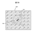
- An image 1300 illustrated in FIG. 13A is an example of a first input image obtained by capturing a fan-shaped object 1301 having a rectangular pattern 1302.
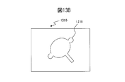
- An image 1310 illustrated in FIG. 13B is an example of a third edge image generated from the first input image 1300. As shown in FIG. 13B, the third edge image 1310 is composed of outer edge pixels 1311, and the rectangular pattern 1302 is not extracted from the third edge image 1310.
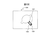
- An image 1320 illustrated in FIG. 13C is an example of a straight line extracted from the third edge image 1310. As shown in FIG. 13C, fan-shaped pattern portions 1321 to 1323 are detected as straight lines from the third edge image 1310. However, in the example shown in FIGS. 13A to 13C, a rectangle composed of four straight lines, each of which is almost orthogonal, is not detected.
- FIG. 14 is a flowchart showing an example of the operation of the non-rectangular detection process. The operation flow shown in FIG. 14 is executed in step S308 of the flowchart shown in FIG.
- the edge pixel extraction unit 201 extracts edge pixels in the horizontal, vertical, and diagonal directions within the candidate area detected by the candidate area detection unit 202.
- the edge pixel extraction unit 201 generates an image composed of pixels extracted as edge pixels in the horizontal, vertical, and diagonal directions as a fourth edge image (step S601).
- the edge pixel extraction unit 201 For each pixel of the first input image, the edge pixel extraction unit 201 has a vertical direction from top to bottom, a horizontal direction from left to right, a diagonal direction from bottom left to top right, and a diagonal direction from bottom right to top left. Each adjacent difference value is calculated. When the absolute value of any calculated adjacent difference value exceeds the threshold value Th1, the edge pixel extraction unit 201 sets the pixel on the image as an edge pixel.
- the edge pixel extraction unit 201 groups the extracted edge pixels by labeling, and removes the edge pixels included in the group whose size is equal to or smaller than the threshold value Th2 (step S602). Thereby, the noise component contained in the fourth edge image can be removed.
- the edge pixel extraction unit 201 generates an expanded image in which the edge pixels are expanded in the generated fourth edge image (step S603). Thereby, even when a part of the connected part is not extracted as an edge pixel in the second input image, the part can be connected in the expanded image.
- the outer peripheral edge pixel extraction unit 206 performs a labeling process on the dilated image with respect to pixels other than the edge pixels (non-edge pixels), and extracts a group connected to the end of the dilated image (step). S604).
- 15A and 15B are schematic diagrams for explaining each image in the non-rectangular detection process.
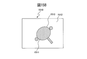
- the group 1502 connected to the end of the expanded image is a group of non-edge pixels located outside the outer periphery of the document 1501.
- the outer peripheral edge pixel extraction unit 206 generates an image in which the pixels included in the extracted group are invalid pixels and other pixels are valid pixels (step S605).
- An image 1510 shown in FIG. 15B is an example of an image generated in step S606.
- the pixels 1512 included in the extracted group are invalid pixels, and the other pixels 1511 are valid pixels.
- the outer peripheral edge pixel extraction unit 206 generates a contracted image in which the effective pixels are contracted in the generated image (step S606).
- This contraction process is executed to return the edge pixel expanded in step S602 to the original size. Therefore, the non-rectangular detection unit 207 contracts the non-rectangle by the same degree as the expansion degree obtained by expanding the edge pixel in step S602. Note that the non-rectangular detection unit 207 may contract the non-rectangle to a degree larger than the expansion degree obtained by expanding the edge pixel in step S602. In this case, when the edge strength of the desk pattern or the like on which the document is placed is high, the edge pixels detected by the desk pattern or the like can be removed from the effective pixels.
- the outer peripheral edge pixel extraction unit 206 extracts edge pixels constituting the outer periphery of the effective pixels of the contracted image as outer peripheral edge pixels (step S607).
- the outer peripheral edge pixel 1513 constituting the outer periphery of the effective pixel 1511 is an edge pixel constituting the outer periphery of the edge pixel to be connected.
- the non-rectangular detection unit 207 detects a non-rectangular shape surrounded by the extracted outer peripheral edge pixels (step S608).
- the non-rectangular detection unit 207 selects only the non-rectangle having the largest area as the detected non-rectangle. Thereby, the noise which generate
- the mask generation unit 208 generates a mask for separating the background from the image to be cut out based on the detected non-rectangular shape (step S609).
- the mask is composed of an image having the same number of pixels as the cut-out image in each of the horizontal and vertical directions, the pixels corresponding to the detected non-rectangular shape as effective pixels, and other pixels as invalid pixels. .
- the information processing apparatus 20 can extract a separated image by extracting only the pixel corresponding to the position of the effective pixel in the mask from the cut image using the mask.
- the image processing circuit 27 may omit the candidate area detection process shown in step S301 of FIG. 5 and execute a rectangular detection process and a non-rectangular detection process on the entire first input image. Even in such a case, the information processing apparatus 20 can appropriately determine an area in which an image of the document is to be cut out.
- the edge pixel extraction unit 201 does not separately detect an edge pixel for detecting a candidate area, an edge pixel for detecting a rectangle, and an edge pixel for detecting a non-rectangular shape.
- a rectangle or a non-rectangular shape may be detected using an edge pixel for detecting.
- the information processing apparatus 20 can reduce the processing load due to the edge pixel detection processing and increase the processing speed.
- the image processing circuit 27 may omit the non-rectangular detection process shown in step S308 of FIG. 5 and may use the candidate area as a non-rectangular when no rectangle is detected.
- the outer edge pixel extraction unit 206 extracts edge pixels that form the outer periphery of the candidate region as outer edge pixels, and the non-rectangular detection unit 207 detects the candidate region as a non-rectangular shape.
- the information processing apparatus 20 can appropriately determine an area where a document image should be cut out. It became.
- the information processing apparatus 20 can accurately detect an area of a document even when an input image has a complicated background.
- the information processing apparatus 20 can accurately detect the outline of the photographing object and delete the background even when the photographing object has a non-rectangular shape such as a three-dimensional object, a hand, or a cutout of a photograph. It became.
- the information processing apparatus 20 uses only vertical and horizontal edge pixels as edge pixels for detecting rectangles, and also uses diagonal edge pixels as edge pixels for detecting non-rectangles. Thereby, when the information processing apparatus 20 detects a rectangle composed of straight lines that can be detected even if some edges are missing, it is difficult to detect that the edges are missing while reducing the influence of noise due to the background or the like. When detecting a non-rectangular shape having a simple curve, it is possible to prevent missing edges.
- FIG. 16 is a diagram showing a schematic configuration of another image processing system 2.
- a difference between the image processing system 2 illustrated in FIG. 16 and the image processing system 1 illustrated in FIG. 1 is that an apparatus including an image processing circuit is different. That is, in the image processing system 2, the image reading device 30 has the image processing circuit 36 instead of the information processing device 40.
- the image processing circuit 36 has the same function as the image processing circuit 27 of the information processing apparatus 20.
- the processing in step S101 and the processing in steps S202 to S203 are mainly performed by the first CPU 35 in cooperation with each element of the image reading device 30 based on a program stored in the first storage device 34 in advance. Executed.
- step S ⁇ b> 101 the image input device 31 of the image reading device 30 generates a read image obtained by photographing the imaging target object and stores it in the first image memory 32. Since the document cut-out process is performed by the image reading device 30, the read image transmission / reception process in steps S102 and S201 is omitted.
- the processing in steps S202 to S203 is executed by the image processing circuit 36 of the image reading apparatus 30.
- the operations of these processes are the same as those executed by the image processing circuit 27 of the information processing apparatus 20 described for the image processing system 1.
- the image processing circuit 36 of the image reading device 30 transmits the clipped region and the separated image to the information processing device 40 via the first interface device 33.
- the image reading apparatus 30 includes the image processing circuit 36 and executes the document cutting process
- the same effect as when the information processing apparatus includes the image processing circuit and executes the document cutting process can be obtained. it can.
- the function sharing between the image reading apparatus and the information processing apparatus is not limited to the example of the image processing system shown in FIGS. 1 and 16, and the image reading apparatus and each part of the information processing apparatus including the respective parts in the image processing circuit are imaged. It can be changed as appropriate in which of the reading apparatus and the information processing apparatus is arranged.
- the image reading device and the information processing device may be configured as a single device.
- the first interface device 13 and the second interface device 21 are connected via a network such as the Internet, a telephone line network (including a mobile terminal line network and a general telephone line network), and an intranet. Also good.
- the first interface device 13 and the second interface device 21 are provided with a communication interface circuit of a network to be connected.
- a plurality of information processing devices 20 are distributed and arranged on the network so that image processing services can be provided in the form of cloud computing, and the information processing devices 20 cooperate to detect straight lines. Processing, rectangle detection processing, and the like may be shared. As a result, the image processing system 1 can efficiently perform the document cutting process on the read images read by the plurality of image reading devices 10.
- the first interface device 33 of the image reading device 30 and the second interface device 41 of the information processing device 40 may be connected via a network.
Landscapes
- Engineering & Computer Science (AREA)
- Multimedia (AREA)
- Signal Processing (AREA)
- Editing Of Facsimile Originals (AREA)
- Image Analysis (AREA)
Abstract
読み取った画像から原稿の画像を切出すべき領域をより精度良く検出する情報処理装置、領域決定方法及びコンピュータプログラムを提供する。画像処理装置は、入力画像からエッジ画素を抽出するエッジ画素抽出部と、エッジ画素のうち外側に位置する外側エッジ画素を抽出する外側エッジ画素抽出部と、外側エッジ画素から矩形を検出する矩形検出部と、エッジ画素のうち連結するエッジ画素の外周を構成する外周エッジ画素を抽出する外周エッジ画素抽出部と、矩形検出部により矩形が検出された場合、検出された矩形を入力画像から原稿の画像を切出す領域に決定し、矩形検出部により矩形が検出されなかった場合、外周エッジ画素抽出部により抽出された外周エッジ画素で囲まれる非矩形を含む領域を入力画像から原稿の画像を切出す領域に決定する領域決定部とを有する。
Description
本発明は、画像処理装置、領域決定方法及びコンピュータプログラムに関し、特に、入力画像から原稿の画像を切出すべき領域を決定する画像処理装置、領域決定方法及びコンピュータプログラムに関する。
スキャナ装置等で原稿を読み取って画像データとして保存するためには、読み取った画像から原稿領域を正確に検出する必要がある。一般に、フラットベッドタイプ又は自動原稿送りタイプのスキャナ装置では、白色、黒色等の単調色の裏当てを用いることにより原稿領域とそれ以外の領域を容易に識別できる。一方、近年では、机等に載置された原稿を読み取るタイプのスキャナ装置が利用されており、机の模様と原稿とを正確に識別することが必要となっている。
カラー画像データから不必要な領域(例えば背景画像領域)について切抜きマスクを作成し、当該マスクで必要な実体部を切抜く方法が開示されている。この方法では、色空間の各軸でヒストグラムの判別分析を行い、分析結果に基づき、分離度の高い軸で分類してクラスタ分けし、分けられたクラスタの中から背景部となるクラスタを指定し、切抜きマスクを作成する(特許文献1を参照)。
また、全幅が裏当て部である領域のイメージデータにより原稿エッジ検出用の基準データを作成し、基準データと画像データとの差異を求めることにより原稿のエッジ検出を行う画像読取装置が開示されている。この画像読取装置は、エッジ検出を水平方向および垂直方向に所定のラインだけ行うことにより原稿の四辺を検出し、原稿画像の自動認識を行う(特許文献2を参照)。
また、入力画像から原稿の境界を検出する画像処理装置が開示されている。この画像処理装置は、入力画像からエッジ画素を抽出し、エッジ画素から複数の直線を抽出し、抽出した直線から矩形候補を抽出し、各矩形候補の各辺から所定距離内にあるエッジ画素の数と各角の角らしさの度合いに基づいて矩形を選択する(特許文献3を参照)。
また、読み取った画像から原稿の画像を切出すべき領域を決定する画像処理装置が開示されている。この画像処理装置は、入力画像から対象領域を検出し、対象領域内において矩形を検出し、その矩形が対象領域と一致する場合、その矩形を切出し領域に決定し、一致しない場合、対象領域を含む領域を切出し領域に決定する(特許文献4を参照)。
スキャナ装置等の画像処理装置では、読み取った画像から原稿の画像を切出すべき領域をより精度良く検出することを求められている。
画像処理装置、領域決定方法及びコンピュータプログラムの目的は、読み取った画像から原稿の画像を切出すべき領域をより精度良く検出することにある。
本実施形態の一側面に係る画像処理装置は、入力画像からエッジ画素を抽出するエッジ画素抽出部と、前記エッジ画素のうち外側に位置する外側エッジ画素を抽出する外側エッジ画素抽出部と、前記外側エッジ画素から矩形を検出する矩形検出部と、前記エッジ画素のうち連結するエッジ画素の外周を構成する外周エッジ画素を抽出する外周エッジ画素抽出部と、前記矩形検出部により矩形が検出された場合、前記検出された矩形を前記入力画像から原稿の画像を切出す領域に決定し、前記矩形検出部により矩形が検出されなかった場合、前記外周エッジ画素抽出部により抽出された外周エッジ画素で囲まれる非矩形を含む領域を前記入力画像から原稿の画像を切出す領域に決定する領域決定部と、を有する。
また、本実施形態の一側面に係る領域決定方法は、入力画像からエッジ画素を抽出し、前記エッジ画素のうち外側に位置する外側エッジ画素を抽出し、前記外側エッジ画素から矩形を検出し、前記エッジ画素のうち連結するエッジ画素の外周を構成する外周エッジ画素を抽出し、前記矩形検出部により矩形が検出された場合、前記検出された矩形を前記入力画像から原稿の画像を切出す領域に決定し、前記矩形検出部により矩形が検出されなかった場合、前記外周エッジ画素抽出部により抽出された外周エッジ画素で囲まれる非矩形を含む領域を前記入力画像から原稿の画像を切出す領域に決定することを含む。
また、本実施形態の一側面に係るコンピュータプログラムは、入力画像からエッジ画素を抽出し、前記エッジ画素のうち外側に位置する外側エッジ画素を抽出し、前記外側エッジ画素から矩形を検出し、前記エッジ画素のうち連結するエッジ画素の外周を構成する外周エッジ画素を抽出し、前記矩形検出部により矩形が検出された場合、前記検出された矩形を前記入力画像から原稿の画像を切出す領域に決定し、前記矩形検出部により矩形が検出されなかった場合、前記外周エッジ画素抽出部により抽出された外周エッジ画素で囲まれる非矩形を含む領域を前記入力画像から原稿の画像を切出す領域に決定することをコンピュータに実行させる。
本実施形態によれば、画像処理装置は、読み取った画像から原稿の画像を切出すべき領域をより精度良く検出することが可能となる。
本発明の目的及び効果は、特に請求項において指摘される構成要素及び組み合わせを用いることによって認識され且つ得られるだろう。前述の一般的な説明及び後述の詳細な説明の両方は、例示的及び説明的なものであり、特許請求の範囲に記載されている本発明を制限するものではない。
以下、本願の一側面に係る情報処理装置、表示方法及び制御プログラムについて図を参照しつつ説明する。但し、本願の技術的範囲はそれらの実施の形態に限定されず、特許請求の範囲に記載された発明とその均等物に及ぶ点に留意されたい。
図1は、実施形態に従った画像処理システムの概略構成を示す図である。図1に示すように、画像処理システム1は、画像読取装置10と、情報処理装置20とを有する。画像読取装置10は、例えばイメージスキャナ、デジタルカメラ等であり、情報処理装置20は、例えば画像読取装置10に接続して用いられるパーソナルコンピュータ等である。
画像読取装置10は、画像入力装置11と、第1画像メモリ12と、第1インターフェース装置13と、第1記憶装置14と、第1CPU(Control Processing Unit)15とを有する。以下、画像読取装置10の各部について詳細に説明する。
画像入力装置11は、撮像対象物である原稿等を撮像する撮像センサを有する。この撮像センサは、撮像素子と、撮像素子に撮像対象物の像を結像する光学系を備える。各撮像素子は、RGB各色に対応するアナログ値を出力する。撮像素子は、1次元又は2次元に配列されたCCD(Charge Coupled Device)、CMOS(Complementary Metal Oxide Semiconductor)等である。画像入力装置11は、撮像センサが出力した各アナログ値をデジタル値に変換して画素データを生成し、生成した各画素データから構成される画像データ(以下、RGB画像と称する)を生成する。このRGB画像は、各画素データが、例えばRGB各色毎に8bitで表される計24bitのRGB値からなるカラー画像データとなる。
画像入力装置11は、RGB画像又はRGB画像の各画素のRGB値を輝度値及び色差値(YUV値)に変換した画像(以下、読取画像と称する)を生成し、第1画像メモリ12に保存する。なお、YUV値は、例えば以下の式により算出することができる。
Y値= 0.30×R値+0.59×G値+0.11×B値 (1)
U値=-0.17×R値-0.33×G値+0.50×B値 (2)
V値= 0.50×R値-0.42×G値-0.08×B値 (3)
Y値= 0.30×R値+0.59×G値+0.11×B値 (1)
U値=-0.17×R値-0.33×G値+0.50×B値 (2)
V値= 0.50×R値-0.42×G値-0.08×B値 (3)
第1画像メモリ12は、不揮発性半導体メモリ、揮発性半導体メモリ、磁気ディスク等の記憶装置を有する。第1画像メモリ12は、画像入力装置11と接続され、画像入力装置11により生成された読取画像を保存する。
第1インターフェース装置13は、USB(Universal Serial Bus)等のシリアルバスに準じるインターフェース回路を有し、情報処理装置20と電気的に接続して画像データ及び各種の情報を送受信する。また、第1インターフェース装置13にフラッシュメモリ等を接続して第1画像メモリ12に保存されている画像データを一旦保存し、情報処理装置20に複写するようにしてもよい。
第1記憶装置14は、RAM(Random Access Memory)、ROM(Read Only Memory)等のメモリ装置、ハードディスク等の固定ディスク装置、又はフレキシブルディスク、光ディスク等の可搬用の記憶装置等を有する。また、第1記憶装置14には、画像読取装置10の各種処理に用いられるコンピュータプログラム、データベース、テーブル等が格納される。コンピュータプログラムは、コンピュータ読み取り可能な可搬型記録媒体から公知のセットアッププログラム等を用いて第1記憶装置14にインストールされてもよい。可搬型記録媒体は、例えばCD-ROM(compact disk read only memory)、DVD-ROM(digital versatile disk read only memory)等である。
第1CPU15は、画像入力装置11、第1画像メモリ12、第1インターフェース装置13及び第1記憶装置14と接続され、これらの各部を制御する。第1CPU15は、画像入力装置11の読取画像生成制御、第1画像メモリ12の制御、第1インターフェース装置13を介した情報処理装置20とのデータ送受信制御、第1記憶装置14の制御等を行う。
情報処理装置20は、第2インターフェース装置21と、第2画像メモリ22と、表示装置23と、入力装置24と、第2記憶装置25と、第2CPU26と、画像処理回路27とを有する。以下、情報処理装置20の各部について詳細に説明する。
第2インターフェース装置21は、画像読取装置10の第1インターフェース装置13と同様のインターフェース回路を有し、情報処理装置20と画像読取装置10とを接続する。
第2画像メモリ22は、画像読取装置10の第1画像メモリ12と同様の記憶装置を有する。第2画像メモリ22には、第2インターフェース装置21を介して画像読取装置10から受信した読取画像を保存するとともに、画像処理回路27と接続され、画像処理回路27により読取画像に対して画像処理がなされた各種の処理画像を保存する。
表示装置23は、液晶、有機EL等から構成されるディスプレイ及びディスプレイに画像データを出力するインターフェース回路を有し、第2画像メモリ22と接続されて第2画像メモリ22に保存されている画像データをディスプレイに表示する。
入力装置24は、キーボード、マウス等の入力装置及び入力装置から信号を取得するインターフェース回路を有し、利用者の操作に応じた信号を第2CPU26に出力する。
第2記憶装置25は、画像読取装置10の第1記憶装置14と同様のメモリ装置、固定ディスク装置、可搬用の記憶装置等を有する。第2記憶装置25には、情報処理装置20の各種処理に用いられるコンピュータプログラム、データベース、テーブル等が格納される。コンピュータプログラムは、例えばCD-ROM、DVD-ROM等のコンピュータ読み取り可能な可搬型記録媒体から、公知のセットアッププログラム等を用いて第2記憶装置25にインストールされてもよい。
第2CPU26は、第2インターフェース装置21、第2画像メモリ22、表示装置23、入力装置24、第2記憶装置25及び画像処理回路27と接続され、これらの各部を制御する。第2CPU26は、第2インターフェース装置21を介した画像読取装置10とのデータ送受信制御、第2画像メモリ22の制御、表示装置23の表示制御、入力装置24の入力制御、第2記憶装置25の制御、画像処理回路27による画像処理の制御等を行う。
画像処理回路27は、第2画像メモリ22に接続され、原稿切出し処理を行う。この画像処理回路27は、第2CPU26に接続され、第2CPU26からの制御により予め第2記憶装置25に記憶されているプログラムに基づいて動作する。なお、画像処理回路27は、独立した集積回路、マイクロプロセッサ、ファームウェア等で構成されてもよい。
図2は、画像処理回路27の概略構成を示す図である。図2に示すように画像処理回路27は、エッジ画素抽出部201、候補領域検出部202、外側エッジ画素抽出部203、直線検出部204、矩形検出部205、外周エッジ画素抽出部206、非矩形検出部207、マスク生成部208、領域決定部209、切出し部210及び記憶制御部211を有する。これらの各部は、プロセッサ上で動作するソフトウェアにより実装される機能モジュールである。なお、これらの各部はそれぞれ独立した集積回路、マイクロプロセッサ、ファームウェア等で構成されてもよい。
図3は、画像読取装置10による画像読取処理の動作を示すフローチャートである。以下、図3に示したフローチャートを参照しつつ、画像読取処理の動作を説明する。なお、以下に説明する動作のフローは、予め第1記憶装置14に記憶されているプログラムに基づき主に第1CPU15により画像読取装置10の各要素と協働して実行される。
最初に、画像入力装置11は、撮像対象物である原稿を撮影した読取画像を生成し、第1画像メモリ12に保存する(ステップS101)。
次に、第1CPU15は、第1画像メモリ12に保存された読取画像を第1インターフェース装置13を介して情報処理装置20に送信し(ステップS102)、一連のステップを終了する。
図4は、情報処理装置20による原稿切出し処理の動作を示すフローチャートである。以下、図4に示したフローチャートを参照しつつ、原稿切出し処理の動作を説明する。なお、以下に説明する動作のフローは、予め第2記憶装置25に記憶されているプログラムに基づき主に第2CPU26により情報処理装置20の各要素と協同して実行される。
最初に、第2CPU26は、読取画像を第2インターフェース装置21を介して画像読取装置10から取得し、第2画像メモリ22に保存する(ステップS201)。
次に、画像処理回路27は、第2画像メモリ22に保存された読取画像を読み出し、読取画像について水平方向及び垂直方向に画素を間引いた第1入力画像を生成し、第2画像メモリ22に保存する(ステップS202)。第1入力画像は入力画像の一例である。
一般に、情報処理装置20は処理する画像の画素数により処理速度が大きく異なるため、画素を間引く割合は、第2CPU26等の処理能力と情報処理装置20に要求される処理速度に応じて定められる。なお、画素を間引かなくても要求される処理速度を満たす場合は読取画像をそのまま第1入力画像としてもよい。
次に、画像処理回路27の各部は、第1入力画像について切出し領域決定処理を実施し(ステップS203)、一連のステップを終了する。切出し領域決定処理において、画像処理回路27の各部は、第1入力画像から原稿の画像を切出す切出し領域を決定する。切出し領域決定処理の詳細については後述する。
図5は、切出し領域決定処理の動作の例を示すフローチャートである。図5に示す動作のフローは、図4に示すフローチャートのステップS203において実行される。
最初に、エッジ画素抽出部201及び候補領域検出部202は、第1入力画像について候補領域検出処理を実施する(ステップS301)。候補領域検出処理において、エッジ画素抽出部201は、第1入力画像からエッジ画素を抽出し、候補領域検出部202は、抽出されたエッジ画素のうち連結するエッジ画素によって囲まれる候補領域を検出する。候補領域検出処理の詳細については後述する。
次に、候補領域検出部202は、候補領域検出処理において候補領域を検出したか否かを判定する(ステップS302)。候補領域検出部202は、候補領域を全く検出していない場合、特に処理を行わず、一連のステップを終了し、一方、候補領域を検出している場合、処理をステップS303へ移行する。ステップS303~S315の処理は、抽出された候補領域ごとに実施される。
次に、エッジ画素抽出部201、外側エッジ画素抽出部203、直線検出部204及び矩形検出部205は、候補領域について矩形検出処理を実施する(ステップS303)。矩形検出処理において、エッジ画素抽出部201は、エッジ画素を抽出し、外側エッジ画素抽出部203は、エッジ画素のうち外側に位置する外側エッジ画素を抽出する。さらに、直線検出部204は、外側エッジ画素から複数の直線を検出し、矩形検出部205は、検出された複数の直線のうち二本ずつが略直交する四本の直線から構成される矩形を検出する。矩形検出処理の詳細については後述する。
次に、領域決定部209は、矩形検出処理において、矩形検出部205により矩形が検出されたか否かを判定する(ステップS304)。領域決定部209は、矩形検出部205により矩形が検出された場合、その検出された矩形を第1入力画像から原稿の画像を切出す切出し領域に決定する(ステップS305)。次に、切出し部210は、決定した切出し領域、即ち検出された矩形を入力画像から切出す(ステップS306)。
次に、記憶制御部211は、切出した画像を第2画像メモリ22に記憶する(ステップS307)。記憶制御部211は、切出した画像を、第2画像メモリ22の内、不揮発性半導体メモリ等の、画像を長期的に記憶する記憶媒体に記憶する。なお、記憶制御部211は、切出した画像を第2記憶装置25のハードディスク等に記憶してもよい。第2画像メモリ22又は第2記憶装置25に記憶された画像は、入力装置24を用いた利用者からの要求に従って、表示装置23に表示される。
一方、エッジ画素抽出部201、外周エッジ画素抽出部206、非矩形検出部207及びマスク生成部208は、矩形検出部205により矩形が検出されなかった場合、候補領域について非矩形検出処理を実施する(ステップS308)。非矩形検出処理において、エッジ画素抽出部201は、エッジ画素を抽出し、外周エッジ画素抽出部206は、抽出されたエッジ画素のうち連結するエッジ画素の外周を構成する外周エッジ画素を抽出する。さらに、非矩形検出部207は、外周エッジ画素で囲まれる非矩形を検出し、マスク生成部208は、検出された非矩形に基づいて、切出される画像から背景を分離するためのマスクを生成する。非矩形検出処理の詳細については後述する。
次に、領域決定部209は、非矩形検出処理において検出された非矩形を含む領域を第1入力画像から原稿の画像を切出す切出し領域に決定する(ステップS309)。領域決定部209は、検出された非矩形の外接矩形を切出し領域に決定する。なお、領域決定部209は、検出された非矩形自体を切出し領域に決定してもよい。次に、切出し部210は、決定した切出し領域を含む領域を第1入力画像から切出す(ステップS310)。さらに、切出し部210は、マスク生成部208が生成したマスクを使用して、切出した画像から背景を分離した、原稿のみを表す分離画像を抽出する。
次に、記憶制御部211は、切出した画像及び分離画像を第2画像メモリ22に記憶する(ステップS311)。記憶制御部211は、切出した画像を、第2画像メモリ22の内、不揮発性半導体メモリ等の、画像を長期的に記憶する記憶媒体に記憶し、分離画像を揮発性半導体メモリ等の、画像を一時的に記憶する記憶媒体に記憶する。なお、記憶制御部211は、切出した画像を第2記憶装置25のハードディスク等に記憶し、分離画像をRAMに記憶してもよい。また、記憶制御部211は、切出した画像をファイルとして記憶し、一方、分離画像を例えばクリップボードに記憶することにより特定のアプリケーションで利用可能に記憶する。これにより、利用者は、文書編集ソフト、画像編集ソフト、表計算ソフト等において、貼付けコマンドのみを実行することにより、分離画像を利用することが可能となり、利用者の利便性を向上させることが可能となる。
なお、記憶制御部211は、矩形を検出した場合と非矩形を検出した場合とで切出した画像(及び分離画像)を保存するファイル形式を変更してもよい。例えば、記憶制御部211は、矩形を検出した場合(ステップS307の場合)、切出した画像をJPEG(Joint Photographic Experts Group)形式で保存する。一方、記憶制御部211は、非矩形を検出した場合(ステップS311の場合)、切出した画像を透過PNG(Portable Network Graphics)形式で保存する。これにより、情報処理装置20は、形状に適した形式で画像を保存することが可能となり、利用者の利便性を向上させることが可能となる。
次に、画像処理回路27は、全ての候補領域について処理したか否かを判定する(ステップS312)。画像処理回路27は、まだ処理していない候補領域がある場合は処理をステップS303に戻して、ステップS303~S312の処理を繰り返し、全ての候補領域について処理した場合は一連のステップを終了する。
図6は、候補領域検出処理の動作の例を示すフローチャートである。図6に示す動作のフローは、図5に示すフローチャートのステップS301において実行される。
最初に、エッジ画素抽出部201は、第1入力画像からさらに水平方向及び垂直方向に画素を間引いた第2入力画像を生成し、第2画像メモリ22に保存する(ステップS401)。第2入力画像は、入力画像の他の例である。
図7A~図7Dは、候補領域検出処理における各画像について説明するための模式図である。図7Aに示す画像700は第1入力画像の例である。図7Aに示すように、第1入力画像700は、木目調等の模様702を有する机に載置された本701を原稿として撮像した画像である。図7Bに示す画像710は第2入力画像の例である。第1入力画像700から第2入力画像710への間引き率は、画像読取装置10の画像入力装置11の撮像素子及び光学系の影響により生じるランダムノイズ703が除去されるが、原稿内の網掛け部分704、文字705等は除去されないように予め定められる。
なお、エッジ画素抽出部201は、第2入力画像を生成する代わりに、第1入力画像に平滑化フィルタを適用することによりランダムノイズ703を除去してもよい。または、エッジ画素抽出部201は、第2入力画像にさらに平滑化フィルタを適用してもよい。
次に、エッジ画素抽出部201は、第2入力画像について水平方向及び垂直方向におけるエッジ画素を抽出する。エッジ画素抽出部201は、第2入力画像の水平方向及び垂直方向の何れかにおいてエッジ画素として抽出された画素からなるエッジ画像を生成し、第2画像メモリ22に保存する(ステップS402)。
エッジ画素抽出部201は、第2入力画像の各画素の水平方向の両隣の画素の輝度値の差の絶対値(以下、隣接差分値と称する)を算出し、隣接差分値が閾値Th1を越える場合、その画像上の画素を垂直エッジ画素とする。この閾値Th1は、例えば、人が画像上の輝度の違いを目視により判別可能な輝度値の差(例えば20)に設定することができる。また、エッジ画素抽出部201は、各画像について垂直方向にも同様の処理を行い、水平エッジ画素を抽出する。なお、エッジ画素抽出部201は、注目画素及びその注目画素の水平方向、垂直方向及び斜め方向(8近傍)に隣接する画素の分散値をその注目画素についての分散値として算出してもよい。その場合、エッジ画素抽出部201は、各画素の分散値についての隣接差分値から垂直エッジ画素及び水平エッジ画素を抽出してもよい。
なお、エッジ画素抽出部201は、抽出した垂直エッジ画素及び水平エッジ画素をそれぞれラベリングによりグループ化し、水平方向の大きさ又は垂直方向の大きさが閾値Th2以下となるグループに含まれるエッジ画素を除去してもよい。閾値Th2は、原稿の載置面の汚れとして想定される値(例えば3mmに相当する値)に設定される。また、エッジ画素抽出部201は、各グループの面積もしくは各グループの外接矩形の面積が閾値以下である場合にそのグループに含まれるエッジ画素を除去してもよい。これらにより、原稿の載置面の汚れにより生じたエッジ画素を除去することができる。
エッジ画素抽出部201は、第2入力画像において垂直エッジ画素又は水平エッジ画素として抽出された画素からなる画像をエッジ画像として生成する。なお、エッジ画素抽出部201は、生成したエッジ画像に対して膨張・収縮処理を実施してもよい。これにより、第2入力画像において連結している部分の一部がエッジ画素として抽出されない場合でも、エッジ画像においてその部分を連結させることができる。
次に、候補領域検出部202は、エッジ画像について、各エッジ画素が他のエッジ画素と連結しているか否かを判定し、連結しているエッジ画素を一つのグループとしてラベリングする(ステップS403)。候補領域検出部202は、水平方向、垂直方向又は斜め方向(8近傍)に相互に隣接するエッジ画素を連結していると判定する。なお、エッジ画素抽出部201は、水平方向又は垂直方向のみ(4近傍)に相互に隣接するエッジ画素を連結していると判定してもよい。
次に、候補領域検出部202は、各グループの水平方向及び垂直方向の両方の大きさが閾値Th3以下か否かを判定し、水平方向及び垂直方向の両方の大きさが閾値Th3以下となるグループに含まれるエッジ画素をエッジ画像から除去する(ステップS404)。閾値Th3は、情報処理装置40が検出を保証する原稿の最小サイズ(例えば1inchに相当する値)に設定される。なお、候補領域検出部202は、各グループの水平方向及び垂直方向の何れかの大きさが閾値Th3以下である場合、又は各グループの面積もしくは各グループの外接矩形の面積が閾値以下である場合にエッジ画素を除去してもよい。外接矩形の面積と比較する閾値は、例えば1inch四方に相当する値とすることができる。
図7Cに示す画像720は、所定の大きさ以下となるグループに含まれるエッジ画素を除去したエッジ画像の例である。画像720では、図7Bに示される机の模様711のように、情報処理装置40が検出を保証する原稿の最小サイズより小さいエッジ画素のグループは除去される。
次に、候補領域検出部202は、各グループが他のグループに包含されるか否かを判定し、他のグループに包含されるグループに含まれるエッジ画素をエッジ画像から除去する(ステップS405)。
図7Dに示す画像730は、他のグループに包含されるグループに含まれるエッジ画素を除去したエッジ画像の例である。画像730では、図7Cに示されるコンテンツ721のように、原稿内のコンテンツによるエッジ画素のグループは除去される。
次に、候補領域検出部202は、除去されずに残った各グループについて、そのグループに含まれるエッジ画素によって囲まれる領域を検出し、検出した領域に対応する第1入力画像内の領域を候補領域として検出する。候補領域検出部202は、第1入力画像内の候補領域の外接矩形を第2画像メモリ22に保存し(ステップS406)、一連のステップを終了する。
図7Dに示す画像730では、連結するエッジ画素によって囲まれる領域は、その連結するエッジ画素のグループの最も外側の外周731及びその内側の領域であり、その領域にはエッジ画素だけでなく、外周731の内側に存在する全ての画素732が含まれる。
なお、連結するエッジ画素によって囲まれる領域を、連結するエッジ画素のグループの最も外側の外周を含まない領域としてもよい。または、連結するエッジ画素によって囲まれる領域を、連結するエッジ画素のグループの最も外側の外周及びその内側の領域を所定画素分だけ膨張又は収縮させた領域としてもよい。また、連結するエッジ画素について、上記したようにエッジ画像に対して膨張・収縮処理を実施することにより、相互に隣接するエッジ画素だけでなく、相互に所定距離内に位置するエッジ画素とその間に位置する画素を含めてもよい。また、連結するエッジ画素の両端に位置するエッジ画素が、所定距離内にある場合は、両端のエッジ画素の間に位置する画素を連結するエッジ画素に含めてもよい。この所定距離は、例えば連結するエッジ画素の長さに所定比率(例えば80%)を乗じた長さとすることができる。これにより、例えばエッジ画素がU字型に連結している場合に、両端のエッジ画素を連結させて囲まれた領域を形成させることができる。
図8は、矩形検出処理の動作の例を示すフローチャートである。図8に示す動作のフローは、図5に示すフローチャートのステップS303において実行される。
最初に、エッジ画素抽出部201は、候補領域検出部202が検出した候補領域内において垂直エッジ画素及び水平エッジ画素を抽出し、垂直エッジ画素又は水平エッジ画素として抽出された画素からなる画像を第2エッジ画像として生成する(ステップS501)。エッジ画素抽出部201は、エッジ画像を生成した場合と同様の方法で垂直エッジ画素及び水平エッジ画素を抽出する。なお、エッジ画像を生成した場合と同様に、エッジ画素抽出部201は、第2入力画像から垂直エッジ画素及び水平エッジ画素を抽出してもよい。また、エッジ画素抽出部201は、抽出した垂直エッジ画素及び水平エッジ画素をそれぞれラベリングによりグループ化し、大きさが閾値Th2以下となるグループに含まれるエッジ画素を除去してもよい。
または、エッジ画素抽出部201は、他の方法により垂直エッジ画素及び水平エッジ画素を抽出してもよい。例えば、エッジ画素抽出部201は、第1入力画像からそれぞれ異なる間引き率で画素を間引いた複数の間引き画像を生成し、第1入力画像及び各間引き画像からそれぞれ垂直エッジ画素を抽出して垂直エッジ画素からなるエッジ画像を生成する。エッジ画素抽出部201は、最も小さい間引き画像から生成したエッジ画像をその次に小さい間引き画像から生成したエッジ画像と同一の解像度に拡大し、同一の解像度にした二つのエッジ画像において同一の位置に存在する垂直エッジ画素からなる画像を生成する。エッジ画素抽出部201は、生成した画像と、その次に小さい間引き画像から生成したエッジ画像に対して同様の処理を繰り返し、最終的に、第1入力画像から生成したエッジ画像の垂直エッジ画素と同一の位置に存在する垂直エッジ画素を抽出する。また、エッジ画素抽出部201は、同様の処理により水平エッジ画素を抽出する。これにより、ノイズを低減しつつ、垂直エッジ画素及び水平エッジ画素を抽出することができる。
なお、エッジ画素抽出部201は、生成した第2エッジ画像に対して膨張・収縮処理を実施しない。これにより、第2エッジ画像では、机の模様、ノイズ等が誤って連結されることが防止される。
次に、外側エッジ画素抽出部203は、候補領域の端部が第1入力画像の端部と近接しているか否かを判定する(ステップS502)。外側エッジ画素抽出部203は、候補領域の左端、右端、上端及び下端の何れかが、第1入力画像の左端、右端、上端又は下端から所定距離内にある場合、近接していると判定し、所定距離内にない場合、近接していないと判定する。所定距離は、候補領域に写っている物が第1入力画像の端部と交わっているにも関わらずエッジ画素が抽出されない可能性のある第1入力画像の端部からの最大距離に定められ、例えば10mmに相当する距離に定められる。
なお、外側エッジ画素抽出部203は、候補領域が、第1入力画像内において予め定められた原稿読取範囲に納まらずにはみ出している場合に候補領域の端部が第1入力画像の端部と近接していると判定し、納まっている場合に近接していないと判定してもよい。その場合、利用者に、原稿を載置する机に原稿読取範囲を示すマットを敷いてから原稿を撮影させることにより、利用者に原稿読取範囲を認識させることができる。なお、画像読取装置10が光照射部(不図示)から、原稿を載置する机に原稿読取範囲を示す光を照射させることにより、利用者に原稿読取範囲を認識させてもよい。
外側エッジ画素抽出部203は、候補領域の端部が第1入力画像の端部と近接していない場合、抽出したエッジ画素のうち外側に位置する外側エッジ画素を抽出する。外側エッジ画素抽出部203は、外側エッジ画素として抽出された画素からなる画像を第3エッジ画像として生成する(ステップS503)。
図9A、図9Bは、外側エッジ画素の抽出処理について説明するための模式図である。図9Aに示す画像900は第2エッジ画像の例である。図9Aに示すように、外側エッジ画素抽出部203は、第2エッジ画像900の各水平ラインを矢印901のように左端側から右端側に向かって走査し、最初に検出したエッジ画素902を外側エッジ画素として抽出する。同様に、外側エッジ画素抽出部203は、第2エッジ画像900の各水平ラインを右端側から左端側に向かって走査し、最初に検出したエッジ画素903も外側エッジ画素として抽出する。同様に、外側エッジ画素抽出部203は、第2エッジ画像900の各垂直ラインを上端側から下端側、及び下端側から上端側に向かってそれぞれ走査し、最初に検出したエッジ画素904、905も外側エッジ画素として抽出する。即ち、外側エッジ画素抽出部203は、候補領域内の各水平ラインにおいて最も左端側及び右端側にそれぞれ位置するエッジ画素、及び候補領域内の各垂直ラインにおいて最も上端側及び下端側にそれぞれ位置するエッジ画素を外側エッジ画素として抽出する。
図9Bに示す画像910は、抽出された外側エッジ画素の例である。図9Bに示すように、外側エッジ画素911は、図9Aの第2エッジ画像900から検出されたエッジ画素902~905から構成される。
一方、外側エッジ画素抽出部203は、候補領域の端部が第1入力画像の端部と近接している場合、候補領域内の全てのエッジ画素からなる画像を第3エッジ画像として生成する(ステップS504)。この場合、後述する矩形処理において、矩形検出部205は、候補領域内の全てのエッジ画素から矩形を検出する。
図10A、図10Bは、候補領域の端部が第1入力画像の端部と近接している例について説明するための模式図である。図10Aに示す画像1000は、原稿1001が利用者の手1002及び1003によりおさえられている状態を示す。この例では、利用者の手1002及び1003によるエッジ画素は、原稿読取範囲1004に納まらずにはみ出し、第1入力画像の端部にまで位置している。図10Bに示す画像1010は、図10Aに示す画像1000から抽出される外側エッジ画素の例である。図10Bに示すように、利用者の手1002及び1003より内側に位置する原稿の端部1005及び1006は、外側エッジ画素1011として抽出されない。このような場合、候補領域内の全てのエッジ画素からなる画像を第3エッジ画像として生成することにより、原稿の端部が抽出されなくなることを防止することができる。
これにより、原稿が載置されている机の模様等のエッジ強度が高い場合にも同様に、原稿の端部から検出されたエッジと机の模様から検出されたエッジとが繋がってしまい、原稿の端部が抽出されなくなることを防止することができる。
なお、外側エッジ画素抽出部203は、候補領域の端部が第1入力画像の端部と近接している場合、候補領域内の一部のエッジ画素を第3エッジ画像から除去してもよい。例えば、外側エッジ画素抽出部203は、候補領域の端部が第1入力画像の水平方向の端部と近接している場合、候補領域内で垂直方向の直線を検出し、候補領域の端部が第1入力画像の垂直方向の端部と近接している場合、候補領域内で水平方向の直線を検出する。外側エッジ画素抽出部203は、最も外側に検出された二つの直線の間にあるエッジ画素を第3エッジ画像から除去する。これにより、原稿内のコンテンツ等を原稿の端部の検出対象から除去することができ、原稿の端部の検出精度を向上させることができる。
次に、直線検出部204は、第3エッジ画像から複数の直線を検出する(ステップS505)。直線検出部204は、ハフ変換を用いて直線を検出する。なお、直線検出部204は、最小二乗法を用いて直線を検出してもよい。または、直線検出部204は、ハフ変換を用いて検出した直線から所定距離内にあるエッジ画素に対して最小二乗法を用いて直線を検出してもよい。この所定距離は、画像処理システム1が使用される環境等に応じて適宜定められ、例えば2mmに相当する距離に設定される。
次に、直線検出部204は、第3エッジ画像から近似直線を検出する(ステップS506)。
図11A及び図11Bは、近似直線について説明するための模式図である。図11Aに示すような書籍原稿を撮影した第1入力画像1100において、書籍原稿の綴じ目部1101に対して平行な端部1102は直線として検出される。しかしながら、綴じ目部1101に対して直交する端部1103は綴じ目部1101の近傍で歪みが生じ、直線として検出されない場合がある。
そこで、直線検出部204は、図11Bのエッジ画像1110に示すように、相互に隣接するエッジ画素1111をラベリングにより一つのグループ1112としてまとめる。直線検出部204は、そのグループ1112に含まれるエッジ画素のうち、水平方向又は垂直方向における両端に位置するエッジ画素1113及びエッジ画素1114を結んだ直線1115を近似直線として検出する。
次に、矩形検出部205は、直線検出部204が検出した直線又は近似直線からなる矩形を検出し(ステップS507)、一連のステップを終了する。
矩形検出部205は、直線検出部204が検出した複数の直線又は近似直線のうち二本ずつが略直交する四本の直線から構成される複数の矩形候補を抽出する。矩形検出部205は、まず水平方向の直線(以下、第1の水平線と称する)を一つ選択し、選択した直線と略平行(例えば±3°以内)かつ閾値Th4以上離れた水平方向の直線(以下、第2の水平線と称する)を抽出する。次に、矩形検出部205は、第1の水平線と略直交する(例えば90°に対して±3°以内)垂直方向の直線(以下、第1の垂直線と称する)を抽出する。次に、矩形検出部205は、第1の水平線と略直交し、かつ第1の垂直線と閾値Th5以上離れた垂直方向の直線(以下、第2の垂直線と称する)を抽出する。なお、閾値Th4及び閾値Th5は、画像読取装置10の読取りの対象となる原稿のサイズに応じて予め定められ、同じ値としてもよい。
矩形検出部205は、直線検出部204が検出した全ての直線又は近似直線について、上記の条件を満たす第1の水平線、第2の水平線、第1の垂直線及び第2の垂直線の全ての組合せを抽出し、抽出した各組合せから構成される矩形を矩形候補として抽出する。矩形検出部205は、抽出した矩形候補について面積を算出し、面積が所定値未満である矩形候補を除去する。矩形検出部205は、残った矩形候補の中で最も面積が大きい矩形候補を矩形として検出する。一方、矩形検出部205は、矩形候補が一つも残らなかった場合、矩形を検出しない。
なお、矩形検出部205は、各矩形候補について、矩形候補の各辺から所定距離(例えば2mmに相当する距離)内にある全ての画素の数に対する所定距離内にあるエッジ画素の数の割合を算出し、矩形候補の面積にその割合を乗じて重み付けしてもよい。これにより、原稿の境界を明確に表している直線から構成される矩形を検出することができる。または、矩形検出部205は、各矩形候補について、矩形候補の各角の角らしさの度合いを表す評価点を算出し、評価点を用いて矩形候補の面積を重み付けしてもよい。
図12は、矩形候補の各角の評価点について説明するための模式図である。図12に示す画像1200において、点1201は矩形候補の角を表し、直線1202、1203は矩形候補の各辺を表す。この直線1202、1203の端部が相互に接している場合は、点1201は矩形の角らしいと考えられるが、直線1202、1203の端部が接していない場合又は直線1202、1203が交差している場合は、点1201は矩形の角らしくないと考えられる。
評価点は0点を基準とする。そして、角1201の近傍における辺1202から所定距離内の領域1204において、水平方向のライン毎にエッジ画素が存在するか否かを判定し、水平方向のラインにエッジ画素が存在する場合、評価点に1点を加算する。なお、各角の近傍の範囲及び各辺からの所定距離は、画像処理システム1が使用される環境等に応じて適宜定められ、例えば各角から5mmに相当する距離内の範囲及び各辺から2mmに相当する距離に設定することができる。同様に、角1201の近傍における辺1203から所定距離内の領域1205において、垂直方向のライン毎にエッジ画素が存在するか否かを判定し、垂直方向のラインにエッジ画素が存在する場合、評価点に1点を加算する。また、角1201の近傍における辺1202の延長線から所定距離内の領域1206において、水平方向のライン毎にエッジ画素が存在するか否かを判定し、水平方向のラインにエッジ画素が存在する場合、評価点から1点を減算する。同様に、角1201の近傍における辺1203の延長線から所定距離内の領域1207において、垂直方向のライン毎にエッジ画素が存在するか否かを判定し、垂直方向のラインにエッジ画素が存在する場合、評価点から1点を減算する。矩形検出部205は、評価点の取り得る最低値が0、取り得る最高値が1となるように評価点を正規化した値を算出し、矩形候補の面積にその値を乗じて重み付けすることにより、四つの角を明確に表している矩形を検出することができる。
図13A~図13Cは、非矩形の画像について矩形検出処理を実行した場合について説明するための模式図である。図13Aに示す画像1300は、矩形状の模様1302を有する、うちわ形状の物1301を撮像した第1入力画像の例である。図13Bに示す画像1310は、第1入力画像1300から生成された第3エッジ画像の例である。図13Bに示すように、第3エッジ画像1310は、外側エッジ画素1311から構成され、第3エッジ画像1310において矩形状の模様1302は抽出されない。図13Cに示す画像1320は、第3エッジ画像1310から抽出された直線の例である。図13Cに示すように、第3エッジ画像1310から、うちわ形状の柄の部分1321~1323が直線として検出される。しかしながら、図13A~図13Cに示す例では、二本ずつが略直交する四本の直線から構成される矩形は検出されない。
図14は、非矩形検出処理の動作の例を示すフローチャートである。図14に示す動作のフローは、図5に示すフローチャートのステップS308において実行される。
最初に、エッジ画素抽出部201は、候補領域検出部202が検出した候補領域内において水平、垂直及び斜め方向にエッジ画素を抽出する。次に、エッジ画素抽出部201は、水平、垂直及び斜め方向にエッジ画素として抽出された画素からなる画像を第4エッジ画像として生成する(ステップS601)。
エッジ画素抽出部201は、第1入力画像の各画素について、上から下へ向かう垂直方向、左から右へ向かう水平方向、左下から右上へ向かう斜め方向、及び右下から左上へ向かう斜め方向の隣接差分値をそれぞれ算出する。エッジ画素抽出部201は、算出した何れかの隣接差分値の絶対値が閾値Th1を越える場合、その画像上の画素をエッジ画素とする。
次に、エッジ画素抽出部201は、抽出したエッジ画素をラベリングによりグループ化し、大きさが閾値Th2以下となるグループに含まれるエッジ画素を除去する(ステップS602)。これにより、第4エッジ画像に含まれるノイズ成分を除去することができる。
次に、エッジ画素抽出部201は、生成した第4エッジ画像において、エッジ画素を膨張させた膨張画像を生成する(ステップS603)。これにより、第2入力画像において、連結している部分の一部がエッジ画素として抽出されない場合でも、膨張画像においてその部分を連結させることができる。
次に、外周エッジ画素抽出部206は、膨張画像に対して、エッジ画素以外の画素(非エッジ画素)についてラベリング処理を実行し、膨張画像の端部と連結しているグループを抽出する(ステップS604)。
図15A、図15Bは、非矩形検出処理における各画像について説明するための模式図である。図15Aに示す画像1500のように、膨張画像の端部と連結しているグループ1502は、原稿1501の外周の外側に位置する非エッジ画素のグループとなる。
次に、外周エッジ画素抽出部206は、抽出したグループに含まれる画素を無効画素とし、他の画素を有効画素とする画像を生成する(ステップS605)。
図15Bに示す画像1510は、ステップS606で生成される画像の例である。画像1510では、抽出したグループに含まれる画素1512が無効画素となり、他の画素1511が有効画素となる。
次に、外周エッジ画素抽出部206は、生成した画像において、有効画素を収縮させた収縮画像を生成する(ステップS606)。この収縮処理は、ステップS602で膨張させたエッジ画素を元のサイズに戻すために実行される。従って、非矩形検出部207は、ステップS602でエッジ画素を膨張させた膨張度合いと同じ度合いだけ非矩形を収縮させる。なお、非矩形検出部207は、ステップS602でエッジ画素を膨張させた膨張度合いより大きい度合いで非矩形を収縮させてもよい。その場合、原稿が載置されている机の模様等のエッジ強度が高い場合に、机の模様等により検出されたエッジ画素を有効画素から除去することができる。
次に、外周エッジ画素抽出部206は、収縮画像の有効画素の外周を構成するエッジ画素を外周エッジ画素として抽出する(ステップS607)。
図15Bに示すように、有効画素1511の外周を構成する外周エッジ画素1513は、連結するエッジ画素の外周を構成するエッジ画素となる。
次に、非矩形検出部207は、抽出された外周エッジ画素で囲まれる非矩形を検出する(ステップS608)。非矩形検出部207は、非矩形を複数検出した場合、最も面積が大きい非矩形のみを、検出した非矩形として選択する。これにより、机の模様等により発生するノイズを除去することができる。
次に、マスク生成部208は、検出された非矩形に基づいて、切出される画像から背景を分離するためのマスクを生成する(ステップS609)。マスクは、水平及び垂直方向のそれぞれにおいて、切出し画像と同数の画素を有し、且つ、検出された非矩形に対応する画素を有効画素とし、他の画素を無効画素とする画像で構成される。情報処理装置20は、マスクを用いて、切出される画像から、マスク内の有効画素の位置に対応する画素のみを抽出することにより、分離画像を抽出することができる。
なお、画像処理回路27は、図5のステップS301に示した候補領域検出処理を省略し、第1入力画像全体に対して、矩形検出処理及び非矩形検出処理を実行してもよい。その場合でも、情報処理装置20は、原稿の画像を切出すべき領域を適切に決定することができる。
また、エッジ画素抽出部201は、候補領域を検出するためのエッジ画素と、矩形を検出するためのエッジ画素と、非矩形を検出するためのエッジ画素とを別個に検出せずに、候補領域を検出するためのエッジ画素を用いて矩形又は非矩形を検出してもよい。その場合、情報処理装置20は、エッジ画素の検出処理による処理負荷を低減し、処理の高速化を図ることができる。
また、画像処理回路27は、図5のステップS308に示した非矩形検出処理を省略し、矩形が検出されなかった場合、候補領域を非矩形として用いてもよい。その場合、外周エッジ画素抽出部206は、候補領域の外周を構成するエッジ画素を外周エッジ画素として抽出し、非矩形検出部207は、候補領域を非矩形として検出する。
以上詳述したように、図4~図6、図8、図14に示したフローチャートに従って動作することによって、情報処理装置20は、原稿の画像を切出すべき領域を適切に決定することが可能となった。特に、情報処理装置20は、入力画像が複雑な背景を有する場合でも、原稿の領域を精度良く検出することが可能となった。さらに、情報処理装置20は、撮影対象物が立体物、手、写真の切抜き等の非矩形の形状を有する場合でも、精度良く撮影対象物の輪郭線を検出し、背景を削除することが可能となった。
また、情報処理装置20は、矩形を検出するためのエッジ画素として垂直及び水平エッジ画素のみを使用し、非矩形を検出するためのエッジ画素として斜めエッジ画素も使用する。これにより、情報処理装置20は、エッジが多少欠落しても検出可能な直線で構成される矩形を検出するときは背景等によるノイズの影響を低減させつつ、エッジが欠落すると検出することが困難な曲線を有する非矩形を検出するときはエッジの欠落を防止できる。
図16は、他の画像処理システム2の概略構成を示す図である。図16に示す画像処理システム2と、図1に示す画像処理システム1との差異は、画像処理回路を備える装置が異なる点である。すなわち、画像処理システム2では、情報処理装置40ではなく、画像読取装置30が画像処理回路36を有する。この画像処理回路36は、情報処理装置20の画像処理回路27と同様の機能を有する。
図16に示す画像処理システム2では、前述した図3、図4に示す処理とほぼ同様の処理を実行することができる。以下、図3のフローチャートに示される画像読取処理並びに図4のフローチャートに示される原稿切出し処理についてどのように適応されるかを説明する。画像処理システム2では、ステップS101の処理及びステップS202~S203の処理は、予め第1記憶装置34に記憶されているプログラムに基づき主に第1CPU35により画像読取装置30の各要素と協働して実行される。
ステップS101において、画像読取装置30の画像入力装置31は、撮像対象物を撮影した読取画像を生成し、第1画像メモリ32に保存する。原稿切出し処理は、画像読取装置30で実施されるため、ステップS102、S201の読取画像の送受信処理は省略される。
ステップS202~S203の処理は、画像読取装置30の画像処理回路36によって実行される。これらの処理の動作は、画像処理システム1について説明した情報処理装置20の画像処理回路27によって実行される場合と同様である。画像読取装置30の画像処理回路36は、切出した領域及び分離画像を第1インターフェース装置33を介して情報処理装置40に送信する。
このように、画像読取装置30が画像処理回路36を備えて原稿切出し処理を実行する場合も、情報処理装置が画像処理回路を備えて原稿切出し処理を実行する場合と同様の効果を得ることができる。
以上、本発明の好適な実施形態について説明してきたが、本発明はこれらの実施形態に限定されるものではない。例えば、画像読取装置と情報処理装置の機能分担は、図1及び図16に示す画像処理システムの例に限られず、画像処理回路内の各部を含めて画像読取装置及び情報処理装置の各部を画像読取装置と情報処理装置の何れに配置するかは適宜変更可能である。または、画像読取装置と情報処理装置を一つの装置で構成してもよい。
また、画像処理システム1において、第1インターフェース装置13と第2インターフェース装置21は、インターネット、電話回線網(携帯端末回線網、一般電話回線網を含む)、イントラネット等のネットワークを介して接続してもよい。その場合、第1インターフェース装置13及び第2インターフェース装置21に、接続するネットワークの通信インターフェース回路を備える。また、その場合、クラウドコンピューティングの形態で画像処理のサービスを提供できるように、ネットワーク上に複数の情報処理装置20を分散して配置し、各情報処理装置20が協働して、直線検出処理、矩形検出処理等を分担するようにしてもよい。これにより、画像処理システム1は、複数の画像読取装置10が読み取った読取画像について、効率よく原稿切出し処理を実施できる。
同様に、図16に示す画像処理システム2においても、画像読取装置30の第1インターフェース装置33と、情報処理装置40の第2インターフェース装置41をネットワークを介して接続してもよい。
1、2 画像処理システム
10、30 画像読取装置
20、40 情報処理装置
201 エッジ画素抽出部
202 候補領域検出部
203 外側エッジ画素抽出部
204 直線検出部
205 矩形検出部
206 外周エッジ画素抽出部
207 非矩形検出部
208 マスク生成部
209 領域決定部
210 切出し部
211 記憶制御部
10、30 画像読取装置
20、40 情報処理装置
201 エッジ画素抽出部
202 候補領域検出部
203 外側エッジ画素抽出部
204 直線検出部
205 矩形検出部
206 外周エッジ画素抽出部
207 非矩形検出部
208 マスク生成部
209 領域決定部
210 切出し部
211 記憶制御部
Claims (9)
- 入力画像からエッジ画素を抽出するエッジ画素抽出部と、
前記エッジ画素のうち外側に位置する外側エッジ画素を抽出する外側エッジ画素抽出部と、
前記外側エッジ画素から矩形を検出する矩形検出部と、
前記エッジ画素のうち連結するエッジ画素の外周を構成する外周エッジ画素を抽出する外周エッジ画素抽出部と、
前記矩形検出部により矩形が検出された場合、前記検出された矩形を前記入力画像から原稿の画像を切出す領域に決定し、前記矩形検出部により矩形が検出されなかった場合、前記外周エッジ画素抽出部により抽出された外周エッジ画素で囲まれる非矩形を含む領域を前記入力画像から原稿の画像を切出す領域に決定する領域決定部と、
を有することを特徴とする画像処理装置。 - さらに、前記エッジ画素のうち連結するエッジ画素によって囲まれる候補領域を検出する候補領域検出部を有し、
前記外側エッジ画素抽出部は、前記候補領域内において前記外側エッジ画素を抽出する、請求項1に記載の画像処理装置。 - 前記外側エッジ画素抽出部は、前記エッジ画素のうち、前記候補領域内の各水平ラインにおいて最も左端側及び右端側にそれぞれ位置するエッジ画素、及び前記候補領域内の各垂直ラインにおいて最も上端側及び下端側にそれぞれ位置するエッジ画素を前記外側エッジ画素として抽出する、請求項2に記載の画像処理装置。
- 前記矩形検出部は、前記候補領域の端部が前記入力画像の端部と近接している場合、前記候補領域内の全てのエッジ画素から矩形を検出する、請求項2または3に記載の画像処理装置。
- 前記外側エッジ画素抽出部は、前記エッジ画素のうち、前記入力画像から水平及び垂直方向に抽出されたエッジ画素から前記外側エッジ画素を抽出し、
前記外周エッジ画素抽出部は、前記エッジ画素のうち、前記入力画像から水平、垂直及び斜め方向に抽出されたエッジ画素から前記外周エッジ画素を抽出する、請求項1に記載の画像処理装置。 - 前記領域決定部は、前記矩形検出部により矩形が検出されなかった場合、前記非矩形の外接矩形を前記入力画像から原稿の画像を切出す領域に決定し、
さらに、前記矩形検出部により矩形が検出されなかった場合に限り、前記非矩形に基づいて、前記切出される画像から背景を分離するためのマスクを生成するマスク生成部を有する、請求項1~5の何れか一項に記載の画像処理装置。 - さらに、前記マスクを用いて前記切出される画像から背景を分離した画像を特定のアプリケーションで利用可能に記憶する記憶部を有する、請求項6に記載の画像処理装置。
- 入力画像からエッジ画素を抽出し、
前記エッジ画素のうち外側に位置する外側エッジ画素を抽出し、
前記外側エッジ画素から矩形を検出し、
前記エッジ画素のうち連結するエッジ画素の外周を構成する外周エッジ画素を抽出し、
矩形が検出された場合、前記検出された矩形を前記入力画像から原稿の画像を切出す領域に決定し、矩形が検出されなかった場合、前記外周エッジ画素抽出部により抽出された外周エッジ画素で囲まれる非矩形を含む領域を前記入力画像から原稿の画像を切出す領域に決定する、
ことを含むことを特徴とする領域決定方法。 - 入力画像からエッジ画素を抽出し、
前記エッジ画素のうち外側に位置する外側エッジ画素を抽出し、
前記外側エッジ画素から矩形を検出し、
前記エッジ画素のうち連結するエッジ画素の外周を構成する外周エッジ画素を抽出し、
矩形が検出された場合、前記検出された矩形を前記入力画像から原稿の画像を切出す領域に決定し、矩形が検出されなかった場合、前記外周エッジ画素抽出部により抽出された外周エッジ画素で囲まれる非矩形を含む領域を前記入力画像から原稿の画像を切出す領域に決定する、
ことをコンピュータに実行させることを特徴とするコンピュータプログラム。
Priority Applications (2)
| Application Number | Priority Date | Filing Date | Title |
|---|---|---|---|
| JP2017507171A JPWO2016151706A1 (ja) | 2015-03-20 | 2015-03-20 | 画像処理装置、領域決定方法及びコンピュータプログラム |
| PCT/JP2015/058596 WO2016151706A1 (ja) | 2015-03-20 | 2015-03-20 | 画像処理装置、領域決定方法及びコンピュータプログラム |
Applications Claiming Priority (1)
| Application Number | Priority Date | Filing Date | Title |
|---|---|---|---|
| PCT/JP2015/058596 WO2016151706A1 (ja) | 2015-03-20 | 2015-03-20 | 画像処理装置、領域決定方法及びコンピュータプログラム |
Publications (1)
| Publication Number | Publication Date |
|---|---|
| WO2016151706A1 true WO2016151706A1 (ja) | 2016-09-29 |
Family
ID=56978781
Family Applications (1)
| Application Number | Title | Priority Date | Filing Date |
|---|---|---|---|
| PCT/JP2015/058596 Ceased WO2016151706A1 (ja) | 2015-03-20 | 2015-03-20 | 画像処理装置、領域決定方法及びコンピュータプログラム |
Country Status (2)
| Country | Link |
|---|---|
| JP (1) | JPWO2016151706A1 (ja) |
| WO (1) | WO2016151706A1 (ja) |
Citations (2)
| Publication number | Priority date | Publication date | Assignee | Title |
|---|---|---|---|---|
| JPH11313207A (ja) * | 1998-04-09 | 1999-11-09 | Hewlett Packard Co <Hp> | ドキュメント画像の傾き角度決定方法 |
| JP2014195148A (ja) * | 2013-03-28 | 2014-10-09 | Pfu Ltd | 画像処理装置、領域決定方法及びコンピュータプログラム |
Family Cites Families (1)
| Publication number | Priority date | Publication date | Assignee | Title |
|---|---|---|---|---|
| JP6021665B2 (ja) * | 2013-01-30 | 2016-11-09 | 株式会社Pfu | 画像処理装置、画像処理方法及びコンピュータプログラム |
-
2015
- 2015-03-20 WO PCT/JP2015/058596 patent/WO2016151706A1/ja not_active Ceased
- 2015-03-20 JP JP2017507171A patent/JPWO2016151706A1/ja active Pending
Patent Citations (2)
| Publication number | Priority date | Publication date | Assignee | Title |
|---|---|---|---|---|
| JPH11313207A (ja) * | 1998-04-09 | 1999-11-09 | Hewlett Packard Co <Hp> | ドキュメント画像の傾き角度決定方法 |
| JP2014195148A (ja) * | 2013-03-28 | 2014-10-09 | Pfu Ltd | 画像処理装置、領域決定方法及びコンピュータプログラム |
Also Published As
| Publication number | Publication date |
|---|---|
| JPWO2016151706A1 (ja) | 2017-07-27 |
Similar Documents
| Publication | Publication Date | Title |
|---|---|---|
| JP6099686B2 (ja) | 画像処理装置、領域検出方法及びコンピュータプログラム | |
| JP6099457B2 (ja) | 画像処理装置、領域決定方法及びコンピュータプログラム | |
| JP5826081B2 (ja) | 画像処理装置、文字認識方法及びコンピュータプログラム | |
| JP5701182B2 (ja) | 画像処理装置、画像処理方法及びコンピュータプログラム | |
| JP4955096B2 (ja) | 検出装置、検出方法、検出プログラム、および記録媒体 | |
| RU2631765C1 (ru) | Способ и система исправления перспективных искажений в изображениях, занимающих двухстраничный разворот | |
| US10455163B2 (en) | Image processing apparatus that generates a combined image, control method, and storage medium | |
| JP5701181B2 (ja) | 画像処理装置、画像処理方法及びコンピュータプログラム | |
| KR20090004904A (ko) | 모델-기반 디워핑 방법 및 장치 | |
| JP6045625B2 (ja) | 画像処理装置、領域検出方法及びコンピュータプログラム | |
| JP6021665B2 (ja) | 画像処理装置、画像処理方法及びコンピュータプログラム | |
| US10452943B2 (en) | Information processing apparatus, control method of information processing apparatus, and storage medium | |
| KR20120132314A (ko) | 화상 처리 장치, 화상 처리 방법, 및 컴퓨터 판독 가능한 매체 | |
| US20170039721A1 (en) | Pose detection using depth camera | |
| JP5042917B2 (ja) | 画像処理装置およびプログラム | |
| JP6317413B1 (ja) | 画像処理装置、画像処理方法及び画像処理プログラム | |
| WO2016151706A1 (ja) | 画像処理装置、領域決定方法及びコンピュータプログラム | |
| US9031324B2 (en) | Image-processing device specifying encircling line for identifying sub-region of image | |
| JP7478628B2 (ja) | 画像処理装置、制御方法及び制御プログラム | |
| JP2010102376A (ja) | 情報表示画素群抽出方法、情報表示画素群抽出装置及び情報表示画素群抽出プログラム | |
| JP6194677B2 (ja) | 画像処理装置およびプログラム | |
| CN120705349A (zh) | 一种书本图像处理方法及相关装置 | |
| JP2016224598A (ja) | 画像処理プログラム、画像処理装置、及び画像処理方法 |
Legal Events
| Date | Code | Title | Description |
|---|---|---|---|
| 121 | Ep: the epo has been informed by wipo that ep was designated in this application |
Ref document number: 15886263 Country of ref document: EP Kind code of ref document: A1 |
|
| ENP | Entry into the national phase |
Ref document number: 2017507171 Country of ref document: JP Kind code of ref document: A |
|
| NENP | Non-entry into the national phase |
Ref country code: DE |
|
| 122 | Ep: pct application non-entry in european phase |
Ref document number: 15886263 Country of ref document: EP Kind code of ref document: A1 |