WO2016148208A1 - Adhesive sheet for image display device, adhesive layered body for image display device, and image display device - Google Patents
Adhesive sheet for image display device, adhesive layered body for image display device, and image display device Download PDFInfo
- Publication number
- WO2016148208A1 WO2016148208A1 PCT/JP2016/058399 JP2016058399W WO2016148208A1 WO 2016148208 A1 WO2016148208 A1 WO 2016148208A1 JP 2016058399 W JP2016058399 W JP 2016058399W WO 2016148208 A1 WO2016148208 A1 WO 2016148208A1
- Authority
- WO
- WIPO (PCT)
- Prior art keywords
- image display
- display device
- meth
- acrylate
- pressure
- Prior art date
Links
Images


Classifications
-
- C—CHEMISTRY; METALLURGY
- C09—DYES; PAINTS; POLISHES; NATURAL RESINS; ADHESIVES; COMPOSITIONS NOT OTHERWISE PROVIDED FOR; APPLICATIONS OF MATERIALS NOT OTHERWISE PROVIDED FOR
- C09J—ADHESIVES; NON-MECHANICAL ASPECTS OF ADHESIVE PROCESSES IN GENERAL; ADHESIVE PROCESSES NOT PROVIDED FOR ELSEWHERE; USE OF MATERIALS AS ADHESIVES
- C09J7/00—Adhesives in the form of films or foils
- C09J7/10—Adhesives in the form of films or foils without carriers
-
- C—CHEMISTRY; METALLURGY
- C09—DYES; PAINTS; POLISHES; NATURAL RESINS; ADHESIVES; COMPOSITIONS NOT OTHERWISE PROVIDED FOR; APPLICATIONS OF MATERIALS NOT OTHERWISE PROVIDED FOR
- C09J—ADHESIVES; NON-MECHANICAL ASPECTS OF ADHESIVE PROCESSES IN GENERAL; ADHESIVE PROCESSES NOT PROVIDED FOR ELSEWHERE; USE OF MATERIALS AS ADHESIVES
- C09J11/00—Features of adhesives not provided for in group C09J9/00, e.g. additives
- C09J11/02—Non-macromolecular additives
- C09J11/06—Non-macromolecular additives organic
-
- C—CHEMISTRY; METALLURGY
- C09—DYES; PAINTS; POLISHES; NATURAL RESINS; ADHESIVES; COMPOSITIONS NOT OTHERWISE PROVIDED FOR; APPLICATIONS OF MATERIALS NOT OTHERWISE PROVIDED FOR
- C09J—ADHESIVES; NON-MECHANICAL ASPECTS OF ADHESIVE PROCESSES IN GENERAL; ADHESIVE PROCESSES NOT PROVIDED FOR ELSEWHERE; USE OF MATERIALS AS ADHESIVES
- C09J133/00—Adhesives based on homopolymers or copolymers of compounds having one or more unsaturated aliphatic radicals, each having only one carbon-to-carbon double bond, and at least one being terminated by only one carboxyl radical, or of salts, anhydrides, esters, amides, imides, or nitriles thereof; Adhesives based on derivatives of such polymers
- C09J133/04—Homopolymers or copolymers of esters
- C09J133/14—Homopolymers or copolymers of esters of esters containing halogen, nitrogen, sulfur or oxygen atoms in addition to the carboxy oxygen
-
- G—PHYSICS
- G02—OPTICS
- G02F—OPTICAL DEVICES OR ARRANGEMENTS FOR THE CONTROL OF LIGHT BY MODIFICATION OF THE OPTICAL PROPERTIES OF THE MEDIA OF THE ELEMENTS INVOLVED THEREIN; NON-LINEAR OPTICS; FREQUENCY-CHANGING OF LIGHT; OPTICAL LOGIC ELEMENTS; OPTICAL ANALOGUE/DIGITAL CONVERTERS
- G02F1/00—Devices or arrangements for the control of the intensity, colour, phase, polarisation or direction of light arriving from an independent light source, e.g. switching, gating or modulating; Non-linear optics
- G02F1/01—Devices or arrangements for the control of the intensity, colour, phase, polarisation or direction of light arriving from an independent light source, e.g. switching, gating or modulating; Non-linear optics for the control of the intensity, phase, polarisation or colour
- G02F1/13—Devices or arrangements for the control of the intensity, colour, phase, polarisation or direction of light arriving from an independent light source, e.g. switching, gating or modulating; Non-linear optics for the control of the intensity, phase, polarisation or colour based on liquid crystals, e.g. single liquid crystal display cells
- G02F1/133—Constructional arrangements; Operation of liquid crystal cells; Circuit arrangements
- G02F1/1333—Constructional arrangements; Manufacturing methods
-
- G—PHYSICS
- G06—COMPUTING; CALCULATING OR COUNTING
- G06F—ELECTRIC DIGITAL DATA PROCESSING
- G06F3/00—Input arrangements for transferring data to be processed into a form capable of being handled by the computer; Output arrangements for transferring data from processing unit to output unit, e.g. interface arrangements
- G06F3/01—Input arrangements or combined input and output arrangements for interaction between user and computer
- G06F3/03—Arrangements for converting the position or the displacement of a member into a coded form
- G06F3/041—Digitisers, e.g. for touch screens or touch pads, characterised by the transducing means
-
- G—PHYSICS
- G09—EDUCATION; CRYPTOGRAPHY; DISPLAY; ADVERTISING; SEALS
- G09F—DISPLAYING; ADVERTISING; SIGNS; LABELS OR NAME-PLATES; SEALS
- G09F9/00—Indicating arrangements for variable information in which the information is built-up on a support by selection or combination of individual elements
Definitions
- the present invention relates to an adhesive sheet for an image display device, an adhesive laminate for an image display device, and an image display device.
- FIG. 10 shows a schematic diagram of a liquid crystal display device as an example of an image display device.
- a liquid crystal display device with a built-in touch panel is composed of a transparent protective plate D1, a touch panel D2, a polarizing plate D3, and a liquid crystal display cell D4.
- the liquid crystal display device is prevented from cracking, stress and impact are alleviated, and visibility is improved.
- an adhesive layer (transparent resin layer) D5 may be provided between the transparent protective plate and the touch panel
- an adhesive layer (transparent resin layer) D6 may be provided between the touch panel and the polarizing plate.
- the material of the transparent protective plate is mainly made of glass, but it is inexpensive and has excellent impact resistance (such as polycarbonate or polymethyl methacrylate (hereinafter abbreviated as PMMA), polycarbonate / PMMA multilayer product). Replacement is being considered.
- a frame-shaped decorative portion D7 is provided by printing or the like (19 (frame pattern) in FIG. 1 of Patent Document 1).
- a film-like pressure-sensitive adhesive may be used as the pressure-sensitive adhesive that bonds the transparent protective plate.
- An excellent step embedding property is required for an adhesive.
- various film-like pressure-sensitive adhesives for improving such step embedding have been studied (for example, Patent Document 2 and Patent Document 3).
- the film-like pressure sensitive adhesive D9 as described in Patent Document 2 and Patent Document 3 has insufficient step embedding properties when the height of the stepped portion D7 is increased.
- the thickness of the film-like adhesive has been reduced, and if the thickness of the film-like adhesive is thin and the stepped portion is high, the step embedding property of the film-like adhesive becomes more difficult. There is a tendency.
- the present invention has been made in view of the above circumstances, and is excellent in embedding in a step formed on an adherend, and is excellent in workability in a process of processing and bonding into a shape suitable for an image display device. It aims at providing the adhesive sheet for image display apparatuses. Another object of the present invention is to provide an adhesive laminate for an image display device and an image display device using the adhesive sheet for an image display device.
- the pressure-sensitive adhesive sheet for an image display device of the present invention has a tan ⁇ at 40 to 70 ° C. of 0.35 or more, a tensile secant modulus in a tensile stress-strain curve of 0.6 to 1.4 MPa, and a tensile breaking elongation. Is 150 mm or less.
- the pressure-sensitive adhesive sheet for an image display device includes 50 to 90 parts by mass of (a) an alkyl (meth) acrylate having an alkyl group having 1 to 18 carbon atoms, 10 to 30 parts by mass of (b) a (meth) acrylate having a hydroxyl group. And (c) a copolymer of a monomer mixture containing (c) an alicyclic substituent or a (meth) acrylate having a tertiary alkyl group.
- the pressure-sensitive adhesive sheet for an image display device further contains a crosslinking agent.
- the pressure-sensitive adhesive sheet for an image display device further contains an ultraviolet absorber.
- the haze value of the pressure-sensitive adhesive sheet for an image display device is preferably 1.5% or less.
- the present invention also provides a laminate for an image display device, comprising: the pressure-sensitive adhesive sheet for an image display device, and at least a pair of base materials laminated so as to sandwich the pressure-sensitive adhesive sheet for an image display device.
- the adhesive laminate can be easily stored and transported without damaging the adhesive layer.
- the present invention provides an image display unit, a transparent protective plate, an adhesive layer formed from the above-mentioned adhesive sheet for an image display device, which is interposed between the image display unit and the transparent protective plate, or a transparent resin layer that is a cured product thereof.
- An image display device is provided.
- the present invention is formed of the image display unit, the transparent protective plate, the touch panel, the image display unit and the transparent protective plate, or the adhesive sheet for an image display device interposed between the touch panel and the transparent protective plate.
- An image display device comprising: a pressure-sensitive adhesive layer or a transparent resin layer that is a cured product thereof.
- a pressure-sensitive adhesive sheet for an image display device that is excellent in embedding in a step formed on an adherend, and that is processed into a shape suitable for an image display device and has excellent workability in a process of bonding. can do.
- the adhesive laminated body for image displays which used the adhesive sheet for image displays, and an image display can be provided.
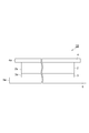
- FIG. 1 is a perspective view showing an embodiment of a laminate (three-layer product) for an image display device according to the present invention.
- FIG. 2 is a side cross-sectional view taken along line II-II in FIG. It is sectional drawing which shows one Embodiment of the image display apparatus of this invention. It is sectional drawing which shows one Embodiment of the image display apparatus of this invention. It is a perspective view which shows one Embodiment of the adhesion laminated body (4 layer goods) which concerns on this invention.
- FIG. 6 is a side sectional view taken along line VI-VI in FIG. 5. It is a schematic diagram which shows the sample measuring method using a wide area dynamic viscoelasticity measuring apparatus.
- the term “(meth) acrylate” means “acrylate” or “methacrylate” corresponding thereto.
- the term “(meth) acryl” means “acryl” or “methacryl” corresponding thereto, and the term “(meth) acryloyl” means “acryloyl” or corresponding “methacryloyl”.
- the pressure-sensitive adhesive sheet for an image display device and the pressure-sensitive adhesive laminate for an image display device are also simply referred to as a pressure-sensitive adhesive sheet and a pressure-sensitive adhesive laminate, respectively.
- the adhesive laminate 1A for an image display device includes an adhesive layer and a pair of base material layers laminated so as to sandwich the adhesive layer. It is preferable that the outer edge of the base material layer projects outward from the outer edge of the adhesive layer.
- the pressure-sensitive adhesive laminate 1 ⁇ / b> A includes a transparent film-like pressure-sensitive adhesive layer 2 and a heavy release separator 3 (one side) sandwiched between the pressure-sensitive adhesive layers 2. And a light release separator 4 (the other substrate). It is preferable that the outer edges of the heavy release separator 3 and the light release separator 4 protrude beyond the outer edge of the adhesive layer 2.
- This adhesive layer 2 is a transparent film disposed between a transparent protective plate and a touch panel or between a touch panel and a liquid crystal display unit in an image display device such as a touch panel display for a portable terminal.
- optically transparent substrates include glass, polycarbonate, polyester (for example, polyethylene terephthalate and polyethylene naphthalate), polyurethane, poly (meth) acrylate (for example, PMMA), polyvinyl alcohol, polyolefin (for example, polyethylene). , Polypropylene, and cellulose triacetate), and the like, are not particularly limited.
- the adhesive layer 2 corresponds to an adhesive sheet for an image display device described later. For this reason, in addition to adhesive force, the adhesion layer 2 has the effect which was more excellent about surface flatness.
- the pressure-sensitive adhesive layer 2 (pressure-sensitive adhesive sheet) according to this embodiment has a tan ⁇ at 40 to 70 ° C. of 0.35 or more, a tensile secant modulus in a tensile stress-strain curve of 0.6 to 1.4 MPa, and The tensile elongation at break is 150 mm or less. According to such an adhesive sheet, it is excellent in embedding in the level difference formed on the adherend, and is excellent in workability in the process of processing into a shape suitable for the image display device and bonding.
- the tan ⁇ at 40 to 70 ° C. of the adhesive layer 2 may be 0.35 to 2.0, 0.4 to 2.0, or 0.4 to 1.9.
- the tan ⁇ at 40 to 70 ° C. is 0.35 or more, the embedding property to the step and the surface flatness tend to be further improved.
- the tan ⁇ at 40 to 70 ° C. is 2 or less, the film formability tends to be good.
- the meaning of the lower limit means that the tan ⁇ value of the adhesive layer (adhesive sheet) is in the entire temperature range of 40 to 70 ° C. It means that it is more than the lower limit. The same applies to the upper limit.
- the tensile secant modulus of the adhesive layer 2 may be 0.6 to 1.4 MPa, or 0.7 to 1.3 MPa.
- the tensile secant modulus of the adhesive layer 2 may be 100 to 300 kPa or 120 to 260 kPa.
- the tensile elongation at break may be 150 mm or less, 130 mm or less, or 120 mm or less.
- Tan ⁇ , tensile secant modulus, and tensile elongation at break are, for example, the composition of the component (A) described later, particularly an alkyl (meth) acrylate having an alkyl group with 4 to 18 carbon atoms and an alicyclic substituent or tertiary. It can also adjust by adjusting the structural ratio of the (meth) acrylate containing an alkyl group and the (meth) acrylate having a hydroxyl group. In particular, tan ⁇ and the tensile secant modulus tend to be in a trade-off relationship, and can be appropriately adjusted based on the ratio of the above-described components.
- the haze of the adhesive layer 2 is preferably 1.5% or less. From the viewpoint of visibility, the haze may be 1.0% or less, 0.8% or less, or 0.5% or less.
- the lower limit of haze is preferably close to 0%, but is usually larger than 0% and may be 0.1% from a practical viewpoint.
- the haze depends on the component (A) described later, and in particular depends on the constituent ratio of the (meth) acrylate containing a hydroxyl group.
- the composition ratio may be 10 to 30 parts by mass or 15 to 30 parts by mass.
- a haze can be made low.
- Haze is a value (%) representing turbidity. From the total transmittance T t of light irradiated by a lamp and transmitted through a sample and the transmittance T d of light diffused and scattered in the sample, ( Td / Tt ) ⁇ 100. These are defined by JIS K 7136, and can be easily measured with a commercially available turbidimeter such as NDH-5000 manufactured by Nippon Denshoku Industries Co., Ltd.
- the thickness of the pressure-sensitive adhesive layer 2 is not particularly limited because it is appropriately adjusted depending on the intended use and method, but may be 25 to 200 ⁇ m, 25 to 180 ⁇ m, or 25 to 150 ⁇ m. When used in this range, it exhibits particularly excellent effects as a transparent adhesive sheet for laminating an optical member on a display.
- the minimum value of the light transmittance for light in the visible light region (wavelength: 380 to 780 nm) of the adhesive layer 2 may be 80%, 90%, or 95%.
- the (A) (meth) acrylic acid derivative polymer is a polymer obtained by polymerizing one type of monomer having one (meth) acryloyl group in the molecule, or by copolymerizing two or more types in combination.
- (A) component is a compound which has 2 or more of (meth) acryloyl groups in a molecule
- a compound having one polymerizable unsaturated bond in the molecule such as acrylonitrile, styrene, vinyl acetate, ethylene, propylene, a compound having two or more polymerizable unsaturated bonds in the molecule such as divinylbenzene
- numerator which forms a component (meth) acrylic acid; (meth) acrylic acid amide; (meth) acryloylmorpholine; methyl (meth) acrylate, Ethyl (meth) acrylate, n-butyl (meth) acrylate, isobutyl (meth) acrylate, tert-butyl (meth) acrylate, n-pentyl (meth) acrylate, n-hexyl (meth) acrylate, n-octyl (meth) Carbon number of alkyl group such as acrylate, isooctyl (meth) acrylate, 2-ethylhexyl (meth) acrylate, isodecyl (meth) acrylate, dodecyl (meth) acrylate (n-lauryl (meth) acrylate
- (meth) acrylate having an aromatic ring such as benzyl (meth) acrylate, phenoxyethyl (meth) acrylate; cyclohexyl (meth) acrylate, isobornyl (meth) acrylate, dicyclopentanyl (meth) acrylate, etc.
- (Meth) acrylates having the following alicyclic substituents; tetrahydrofurfuryl (meth) acrylate; N, N-dimethylaminoethyl (meth) acrylate, N, N-dimethylaminopropyl (meth) acrylamide, N, N— (Meth) acrylamide derivatives such as dimethyl (meth) acrylamide, N-isopropyl (meth) acrylamide, N, N-diethyl (meth) acrylamide, N-hydroxyethyl (meth) acrylamide; 2- (2-methacryloyloxyethyl) Oxy) ethyl isocyanate, 2- (meth) acrylate having an isocyanate group of acryloyloxyethyl isocyanate (meth) acrylates, and alkylene glycol chain-containing (meth) acrylate.
- the component (A) preferably contains an alkyl (meth) acrylate in which the alkyl group represented by the following formula ( ⁇ ) has 1 to 18 carbon atoms. Further, the content ratio of such (meth) acrylate is preferably 50 to 90% by mass, and more preferably 50 to 85% by mass with respect to the total mass of the copolymerized polymer. When the content ratio of (meth) acrylate represented by the following formula ( ⁇ ) is in such a range, the adhesion between the adhesive layer and the transparent protective plate is improved.
- a polymer having such a copolymerization ratio can be obtained by blending each monomer in the same ratio as the above-mentioned copolymerization ratio and copolymerizing them.
- the polymerization rate is more preferably substantially close to 100% by mass.
- CH 2 CXCOOR ( ⁇ )
- X represents a hydrogen atom or a methyl group
- R represents a primary or secondary alkyl group having 1 to 18 carbon atoms.
- alkyl (meth) acrylate having an alkyl group having 1 to 18 carbon atoms examples include methyl (meth) acrylate, ethyl (meth) acrylate, n-butyl (meth) acrylate, isobutyl (meth) acrylate, n-pentyl (meth) ) Acrylate, n-hexyl (meth) acrylate, n-octyl (meth) acrylate, isooctyl (meth) acrylate, 2-ethylhexyl (meth) acrylate, dodecyl (meth) acrylate, stearyl (meth) acrylate, etc.
- n-butyl (meth) acrylate, isooctyl (meth) acrylate, 2-ethylhexyl (meth) acrylate, and n-octyl (meth) acrylate are preferable, and 2-ethylhexyl (meth) acrylate is more preferable.
- alkyl acrylate is more preferable than alkyl methacrylate.
- the component (A) preferably has a monomer containing a hydroxyl group as another monomer copolymerized with an alkyl (meth) acrylate having an alkyl group having 1 to 18 carbon atoms.
- monomers containing hydroxyl groups 2-hydroxyethyl (meth) acrylate, 1-hydroxyethyl (meth) acrylate, 2-hydroxypropyl (meth) acrylate, 3-hydroxypropyl (meth) acrylate, 1-hydroxypropyl (meth) Examples thereof include, but are not limited to, acrylate, 4-hydroxybutyl (meth) acrylate, 3-hydroxybutyl (meth) acrylate, 2-hydroxybutyl (meth) acrylate, 1-hydroxybutyl (meth) acrylate and the like.
- the component (A) has an alicyclic substituent or a tertiary alkyl group as another monomer copolymerized with an alkyl (meth) acrylate having an alkyl group having 1 to 18 carbon atoms (meth).
- An acrylate is mentioned.
- (Meth) acrylates having an alicyclic substituent such as cyclohexyl (meth) acrylate, isobornyl (meth) acrylate, dicyclopentanyl (meth) acrylate, etc.
- Examples of the (meth) acrylate having a tertiary alkyl group include, but are not limited to, tert-butyl (meth) acrylate and the like.
- the (meth) acrylate having an alicyclic substituent or a tertiary alkyl group makes it easier to shorten the tensile fracture elongation while increasing the tan ⁇ of the adhesive layer, and achieves both step embedding and punching workability. Is suitable. Two or more (meth) acrylates having an alicyclic substituent or a tertiary alkyl group may be used in combination.
- alkyl (meth) acrylates having an alkyl group with 1 to 18 carbon atoms include those derived from morpholino groups, amino groups, carboxyl groups, cyano groups, carbonyl groups, nitro groups, and alkylene glycols.
- a monomer having a polar group such as a group is preferred.
- the (meth) acrylate having these polar groups improves the adhesiveness between the adhesive layer and the transparent protective plate.
- alkyl (meth) acrylate having an alkyl group having 1 to 18 carbon atoms and an alkylene glycol chain-containing (meth) acrylate represented by the following formula (x) can be used in combination.
- CH 2 CXCOO (C p H 2p O) q R (x)
- X represents a hydrogen atom or a methyl group
- R represents a hydrogen atom or an alkyl group having 1 to 10 carbon atoms
- p represents an integer of 2 to 4
- q represents an integer of 1 to 10 Show.
- alkylene glycol chain-containing (meth) acrylate represented by the formula (x) include diethylene glycol mono (meth) acrylate, triethylene glycol mono (meth) acrylate, tetraethylene glycol mono (meth) acrylate, and hexaethylene glycol mono (meta).
- Polyethylene glycol mono (meth) acrylates such as acrylate; Polypropylene glycol mono (meth) acrylates such as dipropylene glycol mono (meth) acrylate, tripropylene glycol mono (meth) acrylate, octapropylene glycol mono (meth) acrylate; dibutylene Polybutylene glycol mono (meth) acrylates such as glycol mono (meth) acrylate and tributylene glycol mono (meth) acrylate; Toxitriethylene glycol (meth) acrylate, methoxytetraethylene glycol (meth) acrylate, methoxyhexaethylene glycol (meth) acrylate, methoxyoctaethylene glycol (meth) acrylate, methoxynonaethylene glycol (meth) acrylate, methoxypolyethylene glycol (meta ) Acrylate, methoxyheptapropylene glycol (meth) acrylate, ethoxy
- the pressure-sensitive adhesive sheet comprises 50 to 90 parts by mass of (a) an alkyl (meth) acrylate having an alkyl group having 1 to 18 carbon atoms, 10 to 30 parts by mass of (b) a (meth) acrylate having a hydroxyl group, and 5 to 30
- the copolymer of the monomer mixture containing the (meth) acrylate which has a (c) alicyclic substituent or tertiary alkyl group of a mass part may be included.
- the pressure-sensitive adhesive sheet is 50 to 85 parts by mass of (a) an alkyl (meth) acrylate having 1 to 18 carbon atoms and 10 to 20 parts by mass.
- the weight average molecular weight of the component (A) is preferably 80,000 to 700,000 as converted using a standard polystyrene calibration curve by gel permeation chromatography (GPC).
- GPC gel permeation chromatography
- the weight average molecular weight is 80000 or more, an adhesive layer having an adhesive force that does not peel off from the transparent protective plate or the like can be obtained.
- the viscosity of the adhesive resin composition does not become too high, and the processability when forming a sheet-like adhesive layer tends to be good.
- the weight average molecular weight of the component (A) is more preferably 100,000 to 600,000.
- polymerization method for the component (A) known polymerization methods such as solution polymerization, emulsion polymerization, suspension polymerization, bulk polymerization and the like can be used.
- a compound that generates a radical by heat can be used.
- organic peroxides such as benzoyl peroxide and lauroyl peroxide; 2,2′-azobisisobutyronitrile, 2,2′-azobis (2-methylbutyronitrile), etc. And other azo compounds.
- Specific examples of the component (B) include a photocrosslinking agent and a thermal crosslinking agent.
- Preferred examples of the photocrosslinking agent include compounds represented by the following formulas (a) to (f). However, in formulas (a), (b) and (c), s represents an integer of 1 to 20, and in formulas (d) and (e), m and n each independently represents an integer of 1 to 10. Show.
- urethane di (meth) acrylate having a urethane bond can be used as the component (B).
- the urethane di (meth) acrylate having a urethane bond preferably has a polyalkylene glycol chain from the viewpoint of good compatibility with other components. Moreover, it is preferable to have an alicyclic structure from a viewpoint of ensuring transparency. When the compatibility between the component (B) and the component (A) is high, the cured product tends to be prevented from becoming cloudy.
- the photocrosslinking agent has a weight average molecular weight of preferably 100,000 or less, more preferably 300 to 100,000, and more preferably 500 to 80,000, from the viewpoint of further suppressing the occurrence of bubbles and peeling at high temperature or high temperature and high humidity. More preferably.
- the content is preferably 15% by mass or less with respect to the total mass of the adhesive resin composition.
- the content is 15% by mass or less, since the crosslinking density does not become too high, an adhesive layer having sufficient adhesiveness, high elasticity, and no brittleness can be obtained.
- the content of the photocrosslinking agent is more preferably 10% by mass or less, and further preferably 7% by mass or less.
- a photocrosslinking agent it is preferable that it is 0.1 mass% or more, and it is more preferable that it is 2 mass% or more. More preferably, it is at least mass%.
- thermal cross-linking agent a thermal cross-linking agent such as isocyanate, melamine, or epoxy can be used.
- the thermal crosslinking agent is more preferably a trifunctional or tetrafunctional polyfunctional crosslinking agent in order to form a network structure that gently spreads in the adhesive.
- an isocyanate system is preferred.
- isocyanate type for example, a polyfunctional hexamethylene diisocyanate type compound is preferable.
- a polyfunctional hexamethylene diisocyanate compound for example, a trimer of hexamethylene diisocyanate, a triol such as totimethylolpropane, a reaction product of a diol and hexamethylene diisocyanate, or the like can be given.
- a photopolymerization initiator When either (A) component or (B) component is a curing system using active energy rays, a photopolymerization initiator is required.
- a photoinitiator accelerates
- active energy rays refer to ultraviolet rays, electron beams, ⁇ rays, ⁇ rays, ⁇ rays and the like.
- the photopolymerization initiator is not particularly limited, and known materials such as benzophenone, anthraquinone, benzoyl, sulfonium salt, diazonium salt, onium salt and the like can be used.
- benzophenone, N, N, N ′, N′-tetramethyl-4,4′-diaminobenzophenone (Michler ketone), N, N, N ′, N′-tetraethyl-4,4′-diaminobenzophenone
- Benzophenones such as 4-methoxy-4′-dimethylaminobenzophenone and ⁇ -hydroxyisobutylphenone; 2-ethylanthraquinone, t-butylanthraquinone, 1,4-dimethylanthraquinone, 1-chloroanthraquinone, 2,3-dichloroanthraquinone
- Anthraquinones such as 3-chloro-2-methylanthraquinone, 1,2-benzoanthraquinone, 2-phenylanthraquinone, 1,4-naphthoquinone, 9,10-phenanthraquinone; thi
- 1-hydroxycyclohexyl phenyl ketone, 2-hydroxy-2-methyl-1-phenyl-propan-1-one, 1- [4- (2-hydroxyethoxy) -phenyl] -2 ⁇ -Hydroxyalkylphenone compounds such as hydroxy-2-methyl-1-propan-1-one; bis (2,4,6-trimethylbenzoyl) -phenylphosphine oxide, bis (2,6-dimethoxybenzoyl) Acylphosphine oxide compounds such as -2,4,4-trimethyl-pentylphosphine oxide and 2,4,6-trimethylbenzoyl-diphenylphosphine oxide; oligo (2-hydroxy-2-methyl-1- (4 -(1-Methylvinyl) phenyl) propanone) is preferred.
- the photopolymerization initiator is bis (2,4,6-trimethylbenzoyl) -phenylphosphine oxide, bis (2,6-dimethoxybenzoyl)-
- An acyl phosphine oxide compound such as 2,4,4-trimethyl-pentylphosphine oxide and 2,4,6-trimethylbenzoyl-diphenylphosphine oxide is preferably included.
- the content of the photopolymerization initiator in this embodiment is preferably 0.05 to 5% by mass, more preferably 0.1 to 3% by mass, based on the total mass of the adhesive resin composition. More preferably, the content is 1 to 0.5% by mass.
- the content is preferably 0.05 to 5% by mass or less, there is a tendency that an adhesive layer having high transmittance, a hue that is not yellowish, and excellent in step embedding property can be obtained.
- the adhesive resin composition may contain various additives as necessary.
- various additives that can be contained, for example, a polymerization inhibitor such as paramethoxyphenol added for the purpose of enhancing the storage stability of the adhesive resin composition, an adhesive layer obtained by photocuring the adhesive resin composition, and the like.
- An antioxidant such as triphenyl phosphite added for the purpose of increasing heat resistance, a light stabilizer such as HALS (Hindered Amine Light Stabilizer) added for the purpose of increasing the resistance of the adhesive resin composition to light such as ultraviolet rays,
- HALS Hindered Amine Light Stabilizer
- Examples include a silane coupling agent that is added to increase the adhesion of the adhesive resin composition to glass or the like.
- the pressure-sensitive adhesive laminate for an image display device is obtained by coating the above-mentioned pressure-sensitive adhesive composition on a substrate, and drying and heating or irradiating light when the pressure-sensitive adhesive composition contains an organic solvent.
- 2 can be obtained by covering the pressure-sensitive adhesive layer 2 with another substrate.
- you may make an adhesive resin composition contain a ultraviolet absorber as needed.
- the ultraviolet absorber any compound having absorption in the ultraviolet region can be used.
- benzotriazole-based ultraviolet absorbers for example, Adeka Stab LA-29, LA-31, LA-32 and LA-36 manufactured by ADEKA Corporation, and TinuvinPS, Tinuvin99-2, Tinuvin326, Tinuvin 384 manufactured by BASF Japan Ltd.) -2, Tinuvin 900, Tinuvin 928 and Tinuvin 1130
- benzophenone ultraviolet absorbers for example, Uniul 3049 and Uninul 3050 manufactured by BASF Japan Ltd.
- triazine ultraviolet absorbers for example, ADEKA STAB LA-46 and LA-F70 manufactured by ADEKA Corporation, and BASF Japan Ltd.
- Tinuvin 1600, Tinuvin 1577ED, Tinuvin 400, Tinuvin 405, inuvin460, Tinuvin477 and Tinuvn479) or the like can be used.
- These ultraviolet absorbers may be used alone or in combination of two or more. In the case of using two or more types in combination, it is preferable to adjust the ultraviolet absorption characteristics. By adding the ultraviolet absorber, it is possible to suppress deterioration with time of the display device or the optical film due to ultraviolet rays.
- Examples of the heavy release separator 3 include polymer films such as polyethylene terephthalate, polypropylene, polyethylene, and polyester.
- the polymer film is more preferably a polyethylene terephthalate film (hereinafter sometimes referred to as “PET film”).
- PET film polyethylene terephthalate film
- the thickness of the heavy release separator 3 may be 50 to 200 ⁇ m, 60 to 150 ⁇ m, or 70 to 130 ⁇ m from the viewpoint of workability.
- the planar shape of the heavy release separator 3 is preferably larger than the planar shape of the pressure-sensitive adhesive layer 2, and the outer edge 3 a of the heavy release separator 3 is more preferably projected outward from the outer edge of the pressure-sensitive adhesive layer 2.
- the width of the outer edge of the heavy release separator 3 overhanging the outer edge of the adhesive layer 2 is 2 to 20 mm or 4 to 10 mm from the viewpoint of ease of handling, ease of peeling, and reduction of adhesion of dust and the like. Also good.
- the planar shape of the pressure-sensitive adhesive layer 2 and the heavy release separator 3 is a substantially rectangular shape such as a substantially rectangular shape
- the width at which the outer edge of the heavy release separator 3 protrudes from the outer edge of the pressure-sensitive adhesive layer 2 is 2 at least on one side. It may be ⁇ 20 mm or 4 to 10 mm, or may be 2 to 20 mm or 4 to 10 mm on all sides.
- Examples of the light release separator 4 include polymer films such as polyethylene terephthalate, polypropylene, polyethylene, and polyester. More preferably, the polymer film is a polyethylene terephthalate film.
- the thickness of the light release separator 4 may be 25 to 150 ⁇ m, 30 to 100 ⁇ m, or 40 to 75 ⁇ m from the viewpoint of workability.
- the planar shape of the light release separator 4 is preferably larger than the planar shape of the pressure-sensitive adhesive layer 2, and the outer edge of the light release separator 4 is more preferably projected outward from the outer edge of the pressure-sensitive adhesive layer 2.
- the width at which the outer edge of the light release separator 4 protrudes from the outer edge of the adhesive layer 2 is 2 to 20 mm or 4 to 10 mm from the viewpoint of ease of handling, ease of peeling, and reduction of adhesion of dust and the like. Can do.
- the planar shape of the pressure-sensitive adhesive layer 2 and the light release separator 4 is a substantially rectangular shape such as a substantially rectangular shape
- the width at which the outer edge of the light release separator 4 protrudes from the outer edge of the pressure-sensitive adhesive layer 2 is 2 at least on one side. It may be ⁇ 20 mm or 4 to 10 mm, or may be 2 to 20 mm or 4 to 10 mm on all sides.
- the peel strength between the light release separator 4 and the adhesive layer 2 is preferably lower than the peel strength between the heavy release separator 3 and the adhesive layer 2. Thereby, the heavy release separator 3 is less likely to peel from the adhesive layer 2 than the light release separator 4. Further, when the adhesive sheet is cut, a blade is passed through the adhesive layer 2 toward the heavy release separator 3, so that the outer edge portion of the adhesive layer 2 is pressed against the heavy release separator 3. Thereby, the heavy release separator 3 becomes more difficult to peel from the adhesive layer 2 than the light release separator 4, and the light release separator 4 can be released before the heavy release separator 3 is peeled off.
- the separators 3 and 4 can be peeled one by one, and the operation of peeling the separators 3 and 4 and sticking the adhesive layer 2 to separate adherends can be performed reliably one by one.
- the peel strength between the heavy release separator 3 and the pressure-sensitive adhesive layer 2 and between the light release separator 4 and the pressure-sensitive adhesive layer 2 can be adjusted, for example, by subjecting the heavy release separator 3 and the light release separator 4 to surface treatment.
- the surface treatment method include a mold release treatment with a silicone compound or a fluorine compound.
- the pressure-sensitive adhesive laminate according to this embodiment can be produced, for example, by the method described in International Publication No. 2013/161666.
- the pressure-sensitive adhesive layer 2 included in the pressure-sensitive adhesive laminate 1A can be applied to various image display devices.
- the image display device include a plasma display (PDP), a liquid crystal display (LCD), a cathode ray tube (CRT), a field emission display (FED), an organic EL display (OELD), a 3D display, and electronic paper (EP). .
- the adhesive layer 2 of the present embodiment is used for combining and bonding functional layers having functionality such as an antireflection layer, an antifouling layer, a dye layer, and a hard coat layer of an image display device, and a transparent protective plate. You can also.
- the antireflection layer may be any layer having antireflection properties such that the visible light reflectance is 5% or less, and a layer treated with a known antireflection method on a transparent substrate such as a transparent plastic film. Can be used.
- the antifouling layer is for preventing the surface from getting dirty, and a known layer composed of a fluorine resin or a silicone resin can be used to reduce the surface tension.
- the dye layer is used to increase color purity, and is used to reduce unnecessary light when the color purity of light emitted from an image display unit such as a liquid crystal display unit is low.
- dye which absorbs the light of an unnecessary part can be obtained by making it melt
- the hard coat layer is used to increase the surface hardness.
- a hard-coat layer what formed or laminated
- base films such as a polyethylene film
- a plastic transparent protective plate having a hard coat layer formed or laminated can be used.
- the adhesive layer 2 can be used by being laminated on a polarizing plate. In this case, it can also laminate
- an antireflection layer, an antifouling layer and a hard coat layer can be further laminated on the viewing surface side of the adhesive layer 2.
- a functional layer can be laminated on the viewing surface side of the polarizing plate.
- the adhesive layer 2 can be laminated using a roll laminate, a vacuum bonding machine, or a single wafer bonding machine.
- the adhesive layer 2 is preferably disposed between the image display unit of the image display device and the transparent protective plate on the front side of the viewing side, at an appropriate position on the viewing side. Specifically, it is preferably applied between the image display unit and the transparent protective plate.
- the adhesive layer 2 of the present embodiment is preferably used between the touch panel and the image display unit and / or between the touch panel and the transparent protective plate. If the adhesion layer 2 of this embodiment is applicable on the structure of an image display apparatus, it will not be restricted to the position described above.
- liquid crystal display device which is one of image display devices will be described in detail with reference to FIGS. 3 and 4 as an example.
- FIG. 3 is a side sectional view schematically showing an embodiment of the image display device of the present invention.
- 3 includes an image display unit 7 in which a backlight system 50, a polarizing plate 22, a liquid crystal display cell 12, and a polarizing plate 20 are laminated in this order, and a polarizing plate on the viewing side of the liquid crystal display device.
- the transparent resin layer 32 provided on the upper surface 20 and a transparent protective plate (protective panel) 40 provided on the surface thereof.
- a step portion 60 is provided on the surface of the transparent protective plate 40, thereby forming a step. This step is embedded by a part of the transparent resin layer 32.
- the transparent resin layer 32 basically corresponds to a cured product of the adhesive layer of the present embodiment.
- the thickness of the stepped portion 60 varies depending on the size of the liquid crystal display device and the like, but when the thickness is 40 ⁇ m to 100 ⁇ m, particularly 60 to 100 ⁇ m, it is particularly useful to use the adhesive layer of this embodiment.
- the thickness of the stepped portion 60 is as described above, it is preferable that the thickness of the adhesive layer 2 is thick from the viewpoint of the step embedding property, but the adhesive layer 2 of the present invention is excellent in the step embedding property even if the thickness is small.
- the height of the step portion is h and the thickness of the transparent resin layer is t, excellent step embedding property is obtained even if 0.3 ⁇ (h / t) ⁇ 1.
- FIG. 4 is a side sectional view schematically showing a liquid crystal display device equipped with a touch panel, which is an embodiment of the image display device of the present invention.
- the liquid crystal display device shown in FIG. 4 includes an image display unit 7 in which a backlight system 50, a polarizing plate 22, a liquid crystal display cell 12, and a polarizing plate 20 are laminated in this order, and a polarizing plate on the viewing side of the liquid crystal display device. 20, a transparent resin layer 32 provided on the top surface, a touch panel 30 provided on the top surface of the transparent resin layer 32, a transparent resin layer 31 provided on the top surface of the touch panel 30, and a transparent protective plate provided on the surface thereof 40.
- a step portion 60 is provided on the surface of the transparent protective plate 40, thereby forming a step. This step is embedded by a part of the transparent resin layer 31.
- the transparent resin layer 31 and the transparent resin layer 32 basically correspond to the cured product of the adhesive layer 2 of the present embodiment.
- a transparent resin layer is interposed between the image display unit 7 and the touch panel 30 and between the touch panel 30 and the transparent protective plate 40. It suffices to intervene in at least one of these.
- a transparent resin layer is provided between the touch panel 30 and the transparent protective plate 40 in order to embed a step formed by the stepped portion 60 provided on the surface of the transparent protective plate 40. It is preferable to interpose.
- the touch panel is on-cell, the touch panel and the liquid crystal display cell are integrated.
- the liquid crystal display cell 12 of the liquid crystal display device of FIG. 3 may be replaced with an on-cell.
- the liquid crystal display device provided with such a liquid crystal display cell is composed of a transparent protective plate, a polarizing plate, and a liquid crystal display cell (liquid crystal display cell with a touch panel function). It can also be suitably used for a liquid crystal display device that employs an in-cell touch panel.
- the adhesive layer of this embodiment is provided as the transparent resin layer 31 or 32, it has impact resistance, and there is no double image and a clear and high contrast image. can get.
- the liquid crystal display cell 12 can be made of a liquid crystal material well known in the art. Also, depending on the control method of the liquid crystal material, it is classified into TN (Twisted Nematic) method, STN (Super-Twisted Nematic) method, VA (Vertical Alignment) method, IPS (In-Place-Switching) method, etc. In the form, a liquid crystal display cell using any control method may be used.
- TN Transmission Nematic
- STN Super-Twisted Nematic
- VA Very Alignment
- IPS In-Place-Switching
- polarizing plates 20 and 22 a polarizing plate common in this technical field can be used.
- the surfaces of these polarizing plates may be subjected to treatments such as antireflection, antifouling, and hard coat. Such surface treatment may be performed on one side of the polarizing plate or on both sides thereof.
- the adhesive layer 2 of the present embodiment is particularly suitable for use in a liquid crystal display device that employs a capacitive touch panel.
- a touch panel generally used in this technical field can be used.
- the capacitive touch panel has a structure in which a transparent electrode is formed on a substrate.
- the substrate include a glass substrate, a polyethylene terephthalate film, and a cycloolefin polymer film.
- metal oxides, such as ITO (Indium Tin Oxide) are mentioned, for example.
- the thickness of the substrate is 20 to 1000 ⁇ m.
- the transparent electrode has a thickness of 10 to 500 nm.
- the dielectric constant of the adhesion layer 2 is an appropriate range.
- the dielectric constant at 100 kHz at room temperature (25 ° C.) of the adhesive layer 2 is, for example, 2.0 to 4.5, 2.0 to 4.0, or 3 when the adhesive layer 2 is used between the touch panel and the transparent protective plate. It may be 5 to 4.0. If the dielectric constant is 2.0 or more, the response of the touch panel tends to be sufficiently secured, and if it is 4.0 or less, the malfunction due to the too high response tends to be sufficiently reduced.
- the transparent resin layer 31 or 32 can be formed with a thickness of 0.02 to 3 mm, for example.
- a thicker film can exhibit a more excellent effect, and can be suitably used when forming the transparent resin layer 31 or 32 of 100 to 500 ⁇ m. .
- a general optical transparent substrate can be used as the transparent protective plate 40.
- a general optical transparent substrate include inorganic plates such as glass substrates and quartz plates; plastic substrates such as acrylic resin substrates, polycarbonate plates and cycloolefin polymer plates; resin sheets such as thick polyester sheets.
- inorganic plates such as glass substrates and quartz plates
- plastic substrates such as acrylic resin substrates, polycarbonate plates and cycloolefin polymer plates
- resin sheets such as thick polyester sheets.
- a glass substrate or an acrylic resin substrate may be used, and a glass substrate is more preferable.
- the surface of these transparent protective plates may be subjected to treatments such as antireflection, antifouling, and hard coat. Such surface treatment may be performed on one side of the transparent protective plate or on both sides.
- a plurality of transparent protective plates can be used in combination.
- the backlight system 50 is typically composed of reflecting means such as a reflector and illumination means such as a lamp.
- the image display apparatus can be manufactured, for example, by the method described in International Publication No. 2013/161666.
- the adhesive laminate 1A is used as follows in assembling an image display device or the like. First, the light release separator 4 is peeled from the pressure-sensitive adhesive laminate 1A to expose the pressure-sensitive adhesive surface 2b of the pressure-sensitive adhesive layer 2. Subsequently, the adhesive surface 2b of the adhesive layer 2 is attached to the first adherend, and the adhesive layer 2 is pressed against the second adherend with a roller or the like. At this time, the stepped portion 60 provided on the surface of the first adherend is buried when the adhesive layer 2 flows.
- the adhesive layer 2 When the adhesive layer 2 is pressed against the adherend, the adhesive layer 2 may be heated to 40 to 80 ° C., for example. By heating the pressure-sensitive adhesive layer 2 to 40 to 80 ° C., the pressure-sensitive adhesive layer 2 becomes easier to flow, and the effect of embedding in the stepped portion 60 can be obtained more remarkably. This temperature may be 50 to 70 ° C. because bubbles near the step can be further removed.
- the second adherend is, for example, an image display unit, a transparent protective plate, or a touch panel. Subsequently, the heavy release separator 3 is peeled from the adhesive layer 2 to expose the adhesive surface of the adhesive layer 2.
- the pressure-sensitive adhesive surface of the pressure-sensitive adhesive layer 2 is attached to the second adherend, and a heat and pressure treatment (autoclave treatment) is performed.
- the second adherend is, for example, an image display unit, a transparent protective plate, or a touch panel.
- the adherends can be bonded together via the adhesive layer 2.
- the heat and pressure treatment conditions are such that the temperature is 40 ° C. to 80 ° C. and the pressure is 0.1 MPa to 0.6 MPa, but the step difference on the adherend surface is 30 ⁇ m to 1.0 ⁇ 10 2 ⁇ m.
- the temperature is 50 ° C. to 70 ° C. and the pressure is 0.2 MPa to 0.5 MPa from the viewpoint of further removing bubbles near the step.
- the treatment time is preferably 5 minutes to 60 minutes, and more preferably 10 minutes to 30 minutes.
- the adhesive layer 2 or a transparent resin layer that is a cured product thereof is disposed between the first adherend and the second adherend.
- the adhesive layer 2 transparent resin layer
- the adhesive layer 2 can be disposed between the transparent protective plate and the touch panel, or between the touch panel and the image display unit.
- the liquid crystal display device of FIG. 3 can be manufactured by obtaining a laminate by interposing the adhesive layer 2 of the present embodiment between the image display unit 7 and the transparent protective plate 40. That is, in the image display device illustrated in FIG. 3, the adhesive layer 2 of the present embodiment can be laminated on the upper surface of the polarizing plate 20 by a laminating method.
- the liquid crystal display device of FIG. 4 is manufactured by obtaining the laminate by interposing the adhesive layer 2 of the present embodiment between the image display unit and the touch panel and / or between the touch panel and the transparent protective plate. Can do.
- an image display device in which a decrease in visibility is suppressed by using the pressure-sensitive adhesive sheet of this embodiment.
- the pressure-sensitive adhesive sheet of this embodiment for example, an image display unit such as a liquid crystal display unit and a touch panel, the image display unit and a transparent protective plate, an image display unit and other image displays such as a touch panel and a transparent protective plate, and the like.
- Members (such as optical members) required for the apparatus can be bonded together.
- the manufacturing method according to the present embodiment is particularly useful when the adherend is a transparent protective plate and a touch panel, or a transparent protective plate and an image display unit.
- the pressure-sensitive adhesive sheet of the present embodiment it is possible to bond members on the viewing side of the image display unit of the image display device. In that case, for example, even if the transparent protective plate on the viewing side has a high step portion along the outer peripheral edge thereof, it is assumed that the adhesive layer can surely embed the step, so that the visibility is not lowered. Is done.
- the adhesive laminate 1B for an image display device of the present embodiment is further laminated on a film-like adhesive layer, first and second base material layers laminated so as to sandwich the adhesive layer, and a second base material layer. And the outer edges of the first base material layer and the carrier layer protrude outward from the outer edge of the adhesive layer.
- the pressure-sensitive adhesive laminate 1 ⁇ / b> B includes a transparent film-like pressure-sensitive adhesive layer 2 and a light release separator 4 (first film) laminated so as to sandwich the pressure-sensitive adhesive layer 2.
- first film first film laminated so as to sandwich the pressure-sensitive adhesive layer 2.
- second base material layer first base material layer
- carrier film 5 carrier layer
- the outer edge 5 a of the carrier film 5 projects outward from the outer edge 2 a of the adhesive layer 2. Thereby, the carrier film 5 can be easily peeled from the heavy release separator 3 by pinching the outer edge portion of the carrier film 5 protruding outward.
- the outer edge 5 a of the carrier film 5 projects outward from the outer edge 4 a of the light release separator 4. Thereby, since the outer edge part of the carrier film 5 becomes easier to pinch, the carrier film 5 can be peeled off more easily.
- the width of the portion of the carrier film 5 that protrudes from the outer edge 4a of the light release separator 4 is 0.5 to 10 mm, or 1 to 1 in terms of ease of handling, ease of peeling, and reduction of adhesion of dust and the like.
- the planar shape of the carrier film 5, the adhesive layer 2, the heavy release separator 3 and the light release separator 4 is a substantially rectangular shape such as a substantially rectangular shape, the portion of the carrier film 5 that protrudes from the outer edge 4 a of the light release separator 4.
- the width may be 0.5-10 mm or 1-5 mm on at least one side, or 0.5-10 mm or 1-5 mm on all sides.
- the outer edges of the light release separator 4 and the carrier film 5 protrude outward from the outer edge 2a of the pressure-sensitive adhesive layer 2, so that the pressure-sensitive adhesive layer can be stored and transported. The outer edge can be reliably protected.
- the carrier film 5 When affixing the adhesive layer 2 to an adherend, the carrier film 5 can be easily peeled from the heavy release separator 3 by pinching the outer edge of the carrier film 5 protruding outward.
- the light release separator 4 can be easily peeled by pinching the outer edge 4 a of the light release separator 4.
- the heavy release separator 3 since the heavy release separator 3 remains on one side of the pressure-sensitive adhesive layer 2, when the one surface of the pressure-sensitive adhesive layer 2 is attached to the adherend, the protection of the pressure-sensitive adhesive layer by the heavy release separator 3 is maintained. Thereafter, the heavy release separator 3 is peeled off, and the other surface of the adhesive layer 2 is attached to another adherend, whereby the adhesive layer 2 can be disposed between the pair of adherends.
- the surface of the heavy release separator 3 is less damaged. Therefore, the damage
- Examples of the carrier film 5 include polymer films such as polyethylene terephthalate, polypropylene, polyethylene, and polyester.
- the polymer film may be a polyethylene terephthalate film.
- the thickness of the carrier film 5 may be 15 to 100 ⁇ m, 20 to 80 ⁇ m, or 20 to 50 ⁇ m from the viewpoint of workability.
- the peel strength between the light release separator 4 and the adhesive layer 2 is lower than the peel strength between the heavy release separator 3 and the adhesive layer 2.
- the peel strength between the carrier film 5 and the heavy release separator 3 is lower than the peel strength between the heavy release separator 3 and the adhesive layer 2.
- the peel strength between the carrier film 5 and the heavy release separator 3 is preferably lower than the peel strength between the light release separator 4 and the pressure-sensitive adhesive layer 2, but may be high.
- the peel strength between the carrier film 5 and the heavy release separator 3 may be adjusted by, for example, providing an adhesive layer between the carrier film 5 and the heavy release separator 3.
- the peel strength can be adjusted depending on the type of adhesive layer to be formed and the thickness of the adhesive layer.
- Examples of the type of adhesive formed between the carrier film 5 and the heavy release separator 3 include acrylic adhesives.
- the thickness of the adhesive layer formed between the carrier film 5 and the heavy release separator 3 may be 0.1 to 10 ⁇ m, or 1 to 5 ⁇ m.
- the separators 3 and 4 and the carrier film 5 are reliably peeled in a predetermined order without any defective peeling while protecting the pressure-sensitive adhesive layer 2. be able to.
- the pressure-sensitive adhesive laminate 1B (four-layer product) of this embodiment is the same as the pressure-sensitive adhesive laminate of the first embodiment, except that the carrier film 5 is first peeled off from the heavy release separator 3 before use. Can be used.
- the pressure-sensitive adhesive laminate 1B (four-layer product) of this embodiment is the same as the pressure-sensitive adhesive laminate of the first embodiment, except that the carrier film 5 is first peeled off from the heavy release separator 3 before use. Can be used.
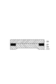
- a support film for evaluating a tensile stress-strain curve having a long side of 70 mm ⁇ a short side of 50 mm ⁇ 0.100 mm (thickness) on two sides of the cut adhesive laminate As a support film for evaluating a tensile stress-strain curve having a long side of 70 mm ⁇ a short side of 50 mm ⁇ 0.100 mm (thickness) on two sides of the cut adhesive laminate, a polyethylene terephthalate film (manufactured by Toyobo Co., Ltd., Cosmo Shine A4300) is used. At 25 ° C. and atmospheric pressure on the long side, a rubber roller (roller diameter: 50 mm, roller width: 210 mm) was applied at a pressure of 0.07 MPa, and the size of the adhesive layer not bonded was 10 mm in length. X The width was set to 50 mm.
- the heavy release separator on the other adhesive layer side that was not bonded to the polyethylene terephthalate film was peeled off to produce a tensile stress-strain curve support film 101 shown in FIG.
- the sample obtained above was measured with a tensile tester (Orientec Co., Ltd., RTC-1210 [trade name]), and the polyethylene terephthalate part of the sample was picked and measured in a 23 ° C. environment at a tensile speed of 300 mm / min. A tensile stress-strain curve was obtained. An example of the obtained tensile stress-strain curve is shown in FIG.
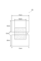
- Step embedding evaluation The produced pressure-sensitive adhesive laminate was cut into a size of 50 mm ⁇ 80 mm ⁇ 0.125 mm.
- the rubber laminate (roller diameter: 50 mm, roller width: 210 mm) was placed on an ITO film of 58 mm ⁇ 86 mm ⁇ 0.125 mm (thickness) on an ITO film (Toyobo Co., Ltd., 300R) at 25 ° C. and atmospheric pressure. was applied at a pressure of 0.07 MPa.
- a pressure-sensitive adhesive sheet is sandwiched between a glass substrate (thickness 0.7 mm) having a stepped portion with an outer peripheral portion printed so as to have a thickness of 35 ⁇ m on the other adhesive layer side to which the ITO film is not bonded.
- a rubber roller roller diameter: 50 mm, roller width: 210 mm
- step-difference part by which the outer peripheral part was printed has the same outer dimension as an ITO film, and has an opening part with an internal dimension of 45 mm x 68 mm.
- the glass substrate was used as a substitute for an input device or an image display device, and the embeddability was evaluated. Thereafter, autoclaving (45 ° C., 0.5 MPa) was performed for 20 minutes to obtain a sample. The obtained sample was left under the following environmental conditions, and a sample treated for a predetermined time was taken out and evaluated.
- An adhesive layer 2 is formed to have a thickness of 125 ⁇ m on the heavy release separator 3 (Toray Film Processing Co., Ltd., Therapy BX8, 50 ⁇ m) shown in FIG. 4 (Toray Film Processing Co., Ltd., therapy BKE, 50 ⁇ m) was formed into a 100 mm ⁇ 200 mm adhesive laminate, and a flat plate punching type punching device (manufactured by Taiwan Manei Machinery Co., Ltd.) A sample of an adhesive laminate was punched at 25 ° C.
- the prepared adhesive laminate was cut into a size of 50 mm ⁇ 50 mm ⁇ 0.125 mm (thickness).
- the cut-out pressure sensitive adhesive sheet was allowed to stand at 85 ° C. and 85% RH for 24 hours, and then the pressure sensitive adhesive sheet was taken out and using a turbidimeter (manufactured by Nippon Denshoku Industries Co., Ltd., NDH-5000) in an OCA single layer state. Measured.
- the produced pressure-sensitive adhesive sheet was cut into a size of 30 mm ⁇ 30 mm ⁇ 0.125 mm (thickness).
- the cut adhesive sheet was stuck on soda lime glass (thickness 0.5 mm) to prepare a test piece.
- the light transmittance in the wavelength range of 200 to 800 nm of the prepared test piece was measured using an ultraviolet-visible-near infrared spectrophotometer (manufactured by JASCO Corporation, instrument name “V570”), and the light transmittance at 380 nm was read. .
- the measurement of the weight average molecular weight was performed using the gel permeation chromatography which used tetrahydrofuran (THF) as a solvent, and it determined using the calibration curve of a standard polystyrene using the following apparatus and measurement conditions.
- Equipment Hitachi, Ltd.
- RI detector L-3350
- Solvent THF
- Column Gelpac GL-R420 + R430 + R440 manufactured by Hitachi Chemical Co., Ltd.
- Production Example 2 Synthesis of (A) (meth) acrylic acid derivative polymer A-2 In a reaction vessel equipped with a cooling tube, a thermometer, a stirrer, a dropping funnel and a nitrogen introduction tube, 2-ethylhexyl acrylate 36 as an initial monomer 0.0 g, 12.0 g of isobornyl acrylate (IBXA), 9.0 g of 2-hydroxyethyl acrylate, 3.0 g of methyl methacrylate, 100.0 g of ethyl acetate, and 20 g of toluene, while substituting nitrogen with an air volume of 100 mL / min And heated from room temperature (25 ° C.) to 80 ° C. in 15 minutes.
- IBXA isobornyl acrylate
- Production Example 4 Synthesis of (A) (meth) acrylic acid derivative polymer A-4 Into a reaction vessel equipped with a cooling tube, a thermometer, a stirrer, a dropping funnel and a nitrogen introducing tube, 2-ethylhexyl acrylate 36 as an initial monomer 0.0 g, 15.0 g of isobornyl acrylate, 9.0 g of 2-hydroxyethyl acrylate, 100.0 g of ethyl acetate, and 20 g of toluene, and at room temperature (25 ° C.) for 15 minutes while substituting nitrogen with an air volume of 100 mL / min To 80 ° C.
- the measurement of the weight average molecular weight was performed using the gel permeation chromatography which used tetrahydrofuran (THF) as a solvent, and it determined using the calibration curve of a standard polystyrene using the following apparatus and measurement conditions.
- Equipment Hitachi, Ltd.
- RI detector L-3350
- Solvent THF
- Column Gelpac GL-R420 + R430 + R440 manufactured by Hitachi Chemical Co., Ltd.
- Production Example 5 Synthesis of (A) (meth) acrylic acid derivative polymer A-5 2-ethylhexyl acrylate 36 as an initial monomer was placed in a reaction vessel equipped with a cooling tube, a thermometer, a stirrer, a dropping funnel and a nitrogen introducing tube. 0.0 g, 15.0 g of methyl methacrylate, 9.0 g of 2-hydroxyethyl acrylate, 100.0 g of ethyl acetate, and 20 g of toluene, and the temperature was changed from room temperature (25 ° C.) to 80 in 15 minutes while purging with nitrogen at an air volume of 100 mL / min. Heated to ° C.
- the measurement of the weight average molecular weight was performed using the gel permeation chromatography which used tetrahydrofuran (THF) as a solvent, and it determined using the calibration curve of a standard polystyrene using the following apparatus and measurement conditions.
- Equipment Hitachi, Ltd.
- RI detector L-3350
- Solvent THF
- Column Gelpac GL-R420 + R430 + R440 manufactured by Hitachi Chemical Co., Ltd.
- Example 1 A polyfunctional hexamethylene diisocyanate compound (Nippon Polyurethane Industry Co., Ltd., Coronate) was used as a thermal crosslinking agent for the solid content of 99.8 parts by mass of the (meth) acrylic acid derivative polymer A-1 solution obtained in Production Example 1. HL) 0.2 parts by mass was weighed and mixed by stirring to obtain an adhesive resin composition for an adhesive sheet. Thereafter, the pressure-sensitive adhesive resin composition for pressure-sensitive adhesive sheet obtained above was dropped onto a polyethylene terephthalate film subjected to mold release treatment on the surface, and applied using a bar coater so that the thickness after drying was 125 ⁇ m.
- Example 2 A pressure-sensitive adhesive laminate was obtained in the same manner as in Example 1 except that the acrylic acid derivative polymer A-2 obtained in Production Example 2 was used in place of the (meth) acrylic acid derivative polymer A-1. The results evaluated in the same manner as in Example 1 are shown in Table 1.
- Example 3 An adhesive laminate was obtained in the same manner as in Example 1 except that the acrylic acid derivative polymer A-3 obtained in Production Example 3 was used instead of the (meth) acrylic acid derivative polymer A-1. The results evaluated in the same manner as in Example 1 are shown in Table 1.
- Example 4 In Example 3, 0.8 parts by mass of benzotriazole compound 1 (manufactured by BASF Japan, Tinuvin 326) and 1.0 part by mass of benzotriazole compound 2 (manufactured by BASF Japan, Tinuvin 928) were weighed as UV absorbers. The obtained pressure-sensitive adhesive resin composition for pressure-sensitive adhesive sheets was stirred and mixed to obtain a resin composition for pressure-sensitive adhesive sheets. The results evaluated in the same manner as in Example 1 are shown in Table 1.
- Comparative Examples 1 and 2 The same procedure as in Example 1 was conducted except that the acrylic acid derivative polymer A-4 obtained in Production Example 4 was used instead of the (meth) acrylic acid derivative polymer A-1 and the formulation shown in Table 1 was used. An adhesive laminate was obtained. The results evaluated in the same manner as in Example 1 are shown in Table 1.
- Comparative Example 3 A pressure-sensitive adhesive laminate was obtained in the same manner as in Example 1 except that the acrylic acid derivative polymer A-5 obtained in Production Example 5 was used in place of the (meth) acrylic acid derivative polymer A-1. The results evaluated in the same manner as in Example 1 are shown in Table 1.
- Comparative Examples 4 and 5 The same procedure as in Example 1 was conducted except that the acrylic acid derivative polymer A-6 obtained in Production Example 6 was used in place of the (meth) acrylic acid derivative polymer A-1, and the formulation shown in Table 1 was used. To obtain an adhesive laminate. The results evaluated in the same manner as in Example 1 are shown in Table 1.
- SYMBOLS 1A, 1B Adhesive laminated body, 2 ... Adhesive layer, 3 ... Heavy release separator, 4 ... Light release separator, 5 ... Carrier film, 2a, 3a, 4a, 5a ... Outer edge, 40 ... Transparent protective board (glass or plastic substrate) , 7 ... Image display unit, 12 ... Liquid crystal display cell, 20, 22 ... Polarizing plate, 30 ... Touch panel, 31, 32 ... Transparent resin layer, 50 ... Backlight system, 60 ... Stepped part, 100 ... Jig, 101 ... Support film for tensile stress-strain curve evaluation.
Abstract
An adhesive sheet for an image display device, in which tan δ at 40-70°C is 0.35 or greater, the tensile secant modulus in the tensile stress-strain curve is 0.6-1.4 MPa, and the tensile elongation at break is 150 mm or less.
Description
本発明は、画像表示装置用粘着シート、画像表示装置用粘着積層体及び画像表示装置に関する。
The present invention relates to an adhesive sheet for an image display device, an adhesive laminate for an image display device, and an image display device.
近年、画像表示装置における透明保護板若しくは情報入力装置(例えばタッチパネル)と画像表示ユニットの表示面との間の空隙、又は透明保護板と情報入力装置との間の空隙を、空気と比較して、屈折率が透明保護板、情報入力装置及び画像表示ユニットの表示面に近い透明材料で置換することにより、透過性を向上させ、画像表示装置の輝度及びコントラストの低下を抑える方法が提案されている(例えば、特許文献1)。画像表示装置の例として液晶表示装置の概略図を図10に示す。タッチパネルを内蔵した液晶表示装置は、透明保護板D1、タッチパネルD2、偏光板D3及び液晶表示セルD4で構成されており、液晶表示装置の割れ防止、応力及び衝撃の緩和、並びに、視認性の向上のために、透明保護板とタッチパネルとの間に粘着層(透明樹脂層)D5が設けられ、さらにタッチパネルと偏光板との間に粘着層(透明樹脂層)D6が設けられる場合もある。また、該透明保護板の材質は、ガラス製が主流であるが、安価で耐衝撃性に優れるプラスチック製(ポリカーボネート又はポリメチルメタクリレート(以下PMMAと略す)、ポリカーボネート・PMMA複層品など)への置き換えが検討されている。
In recent years, a gap between a transparent protective plate or an information input device (for example, a touch panel) in an image display device and a display surface of an image display unit or a gap between a transparent protective plate and an information input device is compared with air. A method has been proposed in which transparency is replaced with a transparent material close to the display surface of the transparent protective plate, the information input device, and the image display unit, thereby improving the transparency and suppressing the decrease in luminance and contrast of the image display device. (For example, Patent Document 1). FIG. 10 shows a schematic diagram of a liquid crystal display device as an example of an image display device. A liquid crystal display device with a built-in touch panel is composed of a transparent protective plate D1, a touch panel D2, a polarizing plate D3, and a liquid crystal display cell D4. The liquid crystal display device is prevented from cracking, stress and impact are alleviated, and visibility is improved. For this reason, an adhesive layer (transparent resin layer) D5 may be provided between the transparent protective plate and the touch panel, and an adhesive layer (transparent resin layer) D6 may be provided between the touch panel and the polarizing plate. The material of the transparent protective plate is mainly made of glass, but it is inexpensive and has excellent impact resistance (such as polycarbonate or polymethyl methacrylate (hereinafter abbreviated as PMMA), polycarbonate / PMMA multilayer product). Replacement is being considered.
ところで、情報入力装置及び画像表示ユニットには、その周縁部分に入出力の配線を設ける必要があり、透明保護板面側からこれらの配線が見えないように、一般に、透明保護板の周縁部分に印刷等で枠状の装飾部D7が設けられる(特許文献1の図1における19(枠パターン)等)。これら装飾部により生じる段差を解消するため、透明保護板を貼り合わせる粘着剤として、例えば、フィルム状の粘着剤が用いられる場合があるが、この段差近傍を隙間無く埋め込むためには、フィルム状の粘着剤に優れた段差埋め込み性が求められる。近年、このような段差埋め込み性を改善するためのフィルム状の粘着剤が、種々検討されている(例えば、特許文献2及び特許文献3)。
By the way, in the information input device and the image display unit, it is necessary to provide input / output wiring at the peripheral portion thereof, and in general, at the peripheral portion of the transparent protective plate so that these wirings cannot be seen from the transparent protective plate surface side. A frame-shaped decorative portion D7 is provided by printing or the like (19 (frame pattern) in FIG. 1 of Patent Document 1). In order to eliminate the level difference caused by these decorative parts, for example, a film-like pressure-sensitive adhesive may be used as the pressure-sensitive adhesive that bonds the transparent protective plate. An excellent step embedding property is required for an adhesive. In recent years, various film-like pressure-sensitive adhesives for improving such step embedding have been studied (for example, Patent Document 2 and Patent Document 3).
しかしながら、図11に示すように、特許文献2及び特許文献3に記載されているようなフィルム状の粘着剤D9は、段差部D7の高さが高くなった場合、段差埋め込み性が十分でないことが、本発明者らの検討の結果明らかとなった。特に最近では、フィルム状の粘着剤の厚さが薄くなってきており、フィルム状の粘着剤の厚さが薄くて段差部が高いと、フィルム状の粘着剤の段差埋め込み性がさらに困難となる傾向にある。また、粘着層の材質を柔らかくすることで段差埋め込み性を向上する手法が挙げられるが、この場合粘着層が柔らかいために、粘着シートを所定のサイズに切断する工程(打抜き加工)において切断面から粘着層が染み出し、セパレータを剥離する際に泣き別れ(両側のセパレータに粘着層が追従する現象)が発生しやすくなり、粘着シートが所定の形状を維持できないために画像表示装置を生産できなくなる又は歩留が悪化する課題があった。
However, as shown in FIG. 11, the film-like pressure sensitive adhesive D9 as described in Patent Document 2 and Patent Document 3 has insufficient step embedding properties when the height of the stepped portion D7 is increased. However, it became clear as a result of examination by the present inventors. Particularly recently, the thickness of the film-like adhesive has been reduced, and if the thickness of the film-like adhesive is thin and the stepped portion is high, the step embedding property of the film-like adhesive becomes more difficult. There is a tendency. In addition, there is a technique to improve the step embedding by softening the material of the adhesive layer. In this case, since the adhesive layer is soft, in the process of cutting the adhesive sheet into a predetermined size (punching process) from the cut surface When the pressure-sensitive adhesive layer oozes out and the separator is peeled off, crying (a phenomenon in which the pressure-sensitive adhesive layer follows the separator on both sides) is likely to occur, and the pressure-sensitive adhesive sheet cannot maintain a predetermined shape, or the image display device cannot be produced. There was a problem that yield deteriorated.
本発明は上記事情を鑑みてなされたものであり、被着物上に形成される段差への埋め込み性に優れ、また、画像表示装置に適した形状に加工し、貼り合わせる過程において加工性に優れる画像表示装置用粘着シートを提供することを目的とする。また本発明は、その画像表示装置用粘着シートを用いた画像表示装置用粘着積層体及び画像表示装置を提供することを目的とする。
The present invention has been made in view of the above circumstances, and is excellent in embedding in a step formed on an adherend, and is excellent in workability in a process of processing and bonding into a shape suitable for an image display device. It aims at providing the adhesive sheet for image display apparatuses. Another object of the present invention is to provide an adhesive laminate for an image display device and an image display device using the adhesive sheet for an image display device.
本発明の画像表示装置用粘着シートは、40~70℃におけるtanδが0.35以上であり、引張応力-ひずみ曲線における引張割線弾性率が0.6~1.4MPaであり、かつ引張破壊伸びが150mm以下である。
The pressure-sensitive adhesive sheet for an image display device of the present invention has a tan δ at 40 to 70 ° C. of 0.35 or more, a tensile secant modulus in a tensile stress-strain curve of 0.6 to 1.4 MPa, and a tensile breaking elongation. Is 150 mm or less.
上記画像表示装置用粘着シートは、50~90質量部の(a)炭素数1~18のアルキル基を有するアルキル(メタ)アクリレート、10~30質量部の(b)水酸基を有する(メタ)アクリレート、及び5~30質量部の(c)脂環式の置換基又は3級アルキル基を有する(メタ)アクリレートを含有するモノマー混合物の共重合体を含むと好ましい。
The pressure-sensitive adhesive sheet for an image display device includes 50 to 90 parts by mass of (a) an alkyl (meth) acrylate having an alkyl group having 1 to 18 carbon atoms, 10 to 30 parts by mass of (b) a (meth) acrylate having a hydroxyl group. And (c) a copolymer of a monomer mixture containing (c) an alicyclic substituent or a (meth) acrylate having a tertiary alkyl group.
上記画像表示装置用粘着シートは、架橋剤をさらに含むと好ましい。
It is preferable that the pressure-sensitive adhesive sheet for an image display device further contains a crosslinking agent.
上記画像表示装置用粘着シートは、紫外線吸収剤をさらに含むと好ましい。
It is preferable that the pressure-sensitive adhesive sheet for an image display device further contains an ultraviolet absorber.
上記画像表示装置用粘着シートのヘイズ値が1.5%以下であると好ましい。
The haze value of the pressure-sensitive adhesive sheet for an image display device is preferably 1.5% or less.
また、本発明は、上記画像表示装置用粘着シートと、上記画像表示装置用粘着シートを挟むように積層された少なくとも一対の基材と、を備える、画像表示装置用積層体を提供する。このような画像表示装置用積層体によれば、粘着層を傷つけることなく、粘着積層体の保管及び運搬を容易にすることができる。
The present invention also provides a laminate for an image display device, comprising: the pressure-sensitive adhesive sheet for an image display device, and at least a pair of base materials laminated so as to sandwich the pressure-sensitive adhesive sheet for an image display device. According to such a laminate for an image display device, the adhesive laminate can be easily stored and transported without damaging the adhesive layer.
本発明は、画像表示ユニットと、透明保護板と、画像表示ユニットと透明保護板との間に介在する、上記画像表示装置用粘着シートから形成される粘着層又はその硬化物である透明樹脂層と、を備える、画像表示装置を提供する。
The present invention provides an image display unit, a transparent protective plate, an adhesive layer formed from the above-mentioned adhesive sheet for an image display device, which is interposed between the image display unit and the transparent protective plate, or a transparent resin layer that is a cured product thereof. An image display device is provided.
本発明は、画像表示ユニットと、透明保護板と、タッチパネルと、画像表示ユニットと透明保護板との間、又はタッチパネルと透明保護板との間に介在する、上記画像表示装置用粘着シートから形成される粘着層又はその硬化物である透明樹脂層と、を備える、画像表示装置を提供する。
The present invention is formed of the image display unit, the transparent protective plate, the touch panel, the image display unit and the transparent protective plate, or the adhesive sheet for an image display device interposed between the touch panel and the transparent protective plate. An image display device comprising: a pressure-sensitive adhesive layer or a transparent resin layer that is a cured product thereof.
本発明によれば、被着物上に形成される段差への埋め込み性に優れ、また、画像表示装置に適した形状に加工し、貼り合わせる過程において加工性に優れる画像表示装置用粘着シートを提供することができる。また本発明によれば、その画像表示装置用粘着シートを用いた画像表示装置用粘着積層体及び画像表示装置を提供することができる。
According to the present invention, there is provided a pressure-sensitive adhesive sheet for an image display device that is excellent in embedding in a step formed on an adherend, and that is processed into a shape suitable for an image display device and has excellent workability in a process of bonding. can do. Moreover, according to this invention, the adhesive laminated body for image displays which used the adhesive sheet for image displays, and an image display can be provided.
以下、本発明の好適な実施形態(第一実施形態及び第二実施形態)について説明をするが、本発明はこれらの実施形態に何ら限定されるものではない。なお、両実施形態で重複する記載については、第一実施形態においてのみ説明するものとし、第二実施形態の説明においては適宜記載を省略する。また、本明細書において「(メタ)アクリレート」という用語は、「アクリレート」又はそれに対応する「メタクリレート」を意味する。同様に「(メタ)アクリル」という用語は、「アクリル」又はそれに対応する「メタクリル」を意味し、「(メタ)アクリロイル」という用語は「アクリロイル」又はそれに対応する「メタクリロイル」を意味する。また、以下では、画像表示装置用粘着シート及び画像表示装置用粘着積層体を単にそれぞれ粘着シート及び粘着積層体とも呼ぶ。
Hereinafter, preferred embodiments (first embodiment and second embodiment) of the present invention will be described, but the present invention is not limited to these embodiments. In addition, the description which overlaps with both embodiment shall be demonstrated only in 1st embodiment, and description is abbreviate | omitted suitably in description of 2nd embodiment. In this specification, the term “(meth) acrylate” means “acrylate” or “methacrylate” corresponding thereto. Similarly, the term “(meth) acryl” means “acryl” or “methacryl” corresponding thereto, and the term “(meth) acryloyl” means “acryloyl” or corresponding “methacryloyl”. Hereinafter, the pressure-sensitive adhesive sheet for an image display device and the pressure-sensitive adhesive laminate for an image display device are also simply referred to as a pressure-sensitive adhesive sheet and a pressure-sensitive adhesive laminate, respectively.
[第一実施形態]
<画像表示装置用粘着積層体I(3層品)>
本実施形態に係る画像表示装置用粘着積層体1Aは、粘着層と、上記粘着層を挟むように積層された一対の基材層と、を備えている。上記基材層の外縁は、上記粘着層の外縁よりも外側に張り出していることが好ましい。 [First embodiment]
<Adhesive Laminate I for Image Display Devices (3-layer product)>
Theadhesive laminate 1A for an image display device according to the present embodiment includes an adhesive layer and a pair of base material layers laminated so as to sandwich the adhesive layer. It is preferable that the outer edge of the base material layer projects outward from the outer edge of the adhesive layer.
<画像表示装置用粘着積層体I(3層品)>
本実施形態に係る画像表示装置用粘着積層体1Aは、粘着層と、上記粘着層を挟むように積層された一対の基材層と、を備えている。上記基材層の外縁は、上記粘着層の外縁よりも外側に張り出していることが好ましい。 [First embodiment]
<Adhesive Laminate I for Image Display Devices (3-layer product)>
The
すなわち、図1及び図2に示されるように、本実施形態に係る粘着積層体1Aは、透明なフィルム状の粘着層2と、粘着層2を挟むように積層された重剥離セパレータ3(一方の基材)及び軽剥離セパレータ4(他方の基材)とを備えている。重剥離セパレータ3及び軽剥離セパレータ4の外縁は、粘着層2の外縁よりも張り出していることが好ましい。この粘着層2は、例えば、携帯端末用のタッチパネル式ディスプレイ等の画像表示装置において、透明保護板とタッチパネルとの間、又はタッチパネルと液晶表示ユニットとの間に配置される透明なフィルムである。
That is, as shown in FIGS. 1 and 2, the pressure-sensitive adhesive laminate 1 </ b> A according to this embodiment includes a transparent film-like pressure-sensitive adhesive layer 2 and a heavy release separator 3 (one side) sandwiched between the pressure-sensitive adhesive layers 2. And a light release separator 4 (the other substrate). It is preferable that the outer edges of the heavy release separator 3 and the light release separator 4 protrude beyond the outer edge of the adhesive layer 2. This adhesive layer 2 is a transparent film disposed between a transparent protective plate and a touch panel or between a touch panel and a liquid crystal display unit in an image display device such as a touch panel display for a portable terminal.
透明保護板は、画像表示装置に用いるため、高い透明性が求められる。光学的に透明な基材の代表例として、ガラス、又はポリカーボネート、ポリエステル(例えば、ポリエチレンテレフタレート及びポリエチレンナフタレート)、ポリウレタン、ポリ(メタ)アクリレート(例えば、PMMA)、ポリビニルアルコール、ポリオレフィン(例えば、ポリエチレン、ポリプロピレン、及びセルローストリアセテート)等を含有するものを含むポリマー基材が挙げられるが、特に限定されるものではない。
Since the transparent protective plate is used for an image display device, high transparency is required. Representative examples of optically transparent substrates include glass, polycarbonate, polyester (for example, polyethylene terephthalate and polyethylene naphthalate), polyurethane, poly (meth) acrylate (for example, PMMA), polyvinyl alcohol, polyolefin (for example, polyethylene). , Polypropylene, and cellulose triacetate), and the like, are not particularly limited.
粘着層2は、後述する画像表示装置用粘着シートに相当する。このため、粘着層2は、粘着力に加え、表面平坦性についてより優れた効果を奏する。
The adhesive layer 2 corresponds to an adhesive sheet for an image display device described later. For this reason, in addition to adhesive force, the adhesion layer 2 has the effect which was more excellent about surface flatness.
本実施形態に係る粘着層2(粘着シート)は、40~70℃におけるtanδが0.35以上であり、引張応力-ひずみ曲線における引張割線弾性率が0.6~1.4MPaであり、かつ引張破壊伸びが150mm以下である。このような粘着シートによれば、被着物上に形成される段差への埋め込み性に優れ、また、画像表示装置に適した形状に加工し、貼り合わせる過程において加工性に優れる。
The pressure-sensitive adhesive layer 2 (pressure-sensitive adhesive sheet) according to this embodiment has a tan δ at 40 to 70 ° C. of 0.35 or more, a tensile secant modulus in a tensile stress-strain curve of 0.6 to 1.4 MPa, and The tensile elongation at break is 150 mm or less. According to such an adhesive sheet, it is excellent in embedding in the level difference formed on the adherend, and is excellent in workability in the process of processing into a shape suitable for the image display device and bonding.
粘着層2の40~70℃でのtanδは、0.35~2.0、0.4~2.0又は0.4~1.9であってもよい。40~70℃でのtanδが0.35以上であると、段差への埋め込み性及び表面平坦性をより向上できる傾向がある。一方、40~70℃でのtanδが2以下であるとフィルム形成性が良好になる傾向がある。ここで、40~70℃でのtanδの範囲について、上記のとおり下限を設定した場合、当該下限の意味は、粘着層(粘着シート)のtanδの値が40~70℃の全温度領域において当該下限以上であることを意味する。上限についても同様である。
The tan δ at 40 to 70 ° C. of the adhesive layer 2 may be 0.35 to 2.0, 0.4 to 2.0, or 0.4 to 1.9. When the tan δ at 40 to 70 ° C. is 0.35 or more, the embedding property to the step and the surface flatness tend to be further improved. On the other hand, if the tan δ at 40 to 70 ° C. is 2 or less, the film formability tends to be good. Here, when the lower limit is set as described above with respect to the range of tan δ at 40 to 70 ° C., the meaning of the lower limit means that the tan δ value of the adhesive layer (adhesive sheet) is in the entire temperature range of 40 to 70 ° C. It means that it is more than the lower limit. The same applies to the upper limit.
粘着層2の引張割線弾性率は、0.6~1.4MPaであってもよく、0.7~1.3MPaであってもよい。なお、粘着層2の引張割線弾性率は、100~300kPa又は120~260kPaであってもよい。また、引張破壊伸びは、150mm以下であってもよく、130mm以下又は120mm以下であってもよい。引張割線弾性率が0.6~1.4MPaかつ引張破壊伸びが150mm以下であると、粘着シートを所定のサイズに切断する際の加工性に優れ、画像表示装置に組み込む際の作業性にも優れる傾向がある。
The tensile secant modulus of the adhesive layer 2 may be 0.6 to 1.4 MPa, or 0.7 to 1.3 MPa. The tensile secant modulus of the adhesive layer 2 may be 100 to 300 kPa or 120 to 260 kPa. Further, the tensile elongation at break may be 150 mm or less, 130 mm or less, or 120 mm or less. When the tensile secant modulus is 0.6 to 1.4 MPa and the tensile elongation at break is 150 mm or less, the workability when cutting the adhesive sheet to a predetermined size is excellent, and the workability when incorporating it into an image display device is also good. There is a tendency to excel.
tanδ、引張割線弾性率、引張破壊伸びは、例えば、後述する(A)成分の組成、とりわけアルキル基の炭素数が4~18であるアルキル(メタ)アクリレートと脂環式の置換基又は3級アルキル基を含有する(メタ)アクリレートと水酸基を有する(メタ)アクリレートの構成比率を調整することによって調節することもできる。特にtanδと引張割線弾性率はトレードオフの関係になる傾向にあり、前述の構成成分の比率等から適宜調整することもできる。
Tan δ, tensile secant modulus, and tensile elongation at break are, for example, the composition of the component (A) described later, particularly an alkyl (meth) acrylate having an alkyl group with 4 to 18 carbon atoms and an alicyclic substituent or tertiary. It can also adjust by adjusting the structural ratio of the (meth) acrylate containing an alkyl group and the (meth) acrylate having a hydroxyl group. In particular, tan δ and the tensile secant modulus tend to be in a trade-off relationship, and can be appropriately adjusted based on the ratio of the above-described components.
画像表示装置に用いるため、粘着層2のヘイズ(Haze)は1.5%以下であることが好ましい。視認性の観点から、ヘイズは、1.0%以下、0.8%以下、又は0.5%以下であってもよい。ヘイズの下限値については0%に近いことが好ましいが、通常は0%より大きく、実用的な観点からは0.1%であってよい。
For use in an image display device, the haze of the adhesive layer 2 is preferably 1.5% or less. From the viewpoint of visibility, the haze may be 1.0% or less, 0.8% or less, or 0.5% or less. The lower limit of haze is preferably close to 0%, but is usually larger than 0% and may be 0.1% from a practical viewpoint.
ヘイズは、後述する(A)成分に依存し、とりわけ水酸基を含有する(メタ)アクリレートの構成比率に依存する。水酸基を含有する(メタ)アクリレートの構成比率が高い場合、信頼性試験(加熱加湿条件)により白化しにくくなり、ヘイズが低くなるため好ましい。構成比率は、10~30質量部又は15~30質量部であっても良い。また、後述する(A)成分及び(B)成分の相溶性が良好であればヘイズを低くすることができる。
The haze depends on the component (A) described later, and in particular depends on the constituent ratio of the (meth) acrylate containing a hydroxyl group. When the composition ratio of the (meth) acrylate containing a hydroxyl group is high, it is difficult to whiten by a reliability test (heating and humidifying conditions), and the haze is preferably reduced. The composition ratio may be 10 to 30 parts by mass or 15 to 30 parts by mass. Moreover, if the compatibility of (A) component and (B) component mentioned later is favorable, a haze can be made low.
ヘイズとは、濁度を表わす値(%)であり、ランプにより照射され、試料中を透過した光の全透過率Ttと、試料中で拡散され散乱した光の透過率Tdより、(Td/Tt)×100として求められる。これらはJIS K 7136により規定されており、市販の濁度計、例えば、日本電色工業株式会社製NDH-5000により容易に測定可能である。
Haze is a value (%) representing turbidity. From the total transmittance T t of light irradiated by a lamp and transmitted through a sample and the transmittance T d of light diffused and scattered in the sample, ( Td / Tt ) × 100. These are defined by JIS K 7136, and can be easily measured with a commercially available turbidimeter such as NDH-5000 manufactured by Nippon Denshoku Industries Co., Ltd.
粘着層2の厚さは、使用用途及び方法により適宜調整されるため特に限定されないが、25~200μm、25~180μm、又は25~150μmであってもよい。この範囲で使用した場合、ディスプレイ上に光学部材を貼合せるための透明な粘着シートとして特に優れた効果を発揮する。
The thickness of the pressure-sensitive adhesive layer 2 is not particularly limited because it is appropriately adjusted depending on the intended use and method, but may be 25 to 200 μm, 25 to 180 μm, or 25 to 150 μm. When used in this range, it exhibits particularly excellent effects as a transparent adhesive sheet for laminating an optical member on a display.
粘着層2の可視光領域(波長:380~780nm)の光線に対する光透過率の最小値は、80%、90%、又は95%であってもよい。
The minimum value of the light transmittance for light in the visible light region (wavelength: 380 to 780 nm) of the adhesive layer 2 may be 80%, 90%, or 95%.
次に、本実施形態に係る画像表示装置用粘着シートの成分について説明する。
[(A)成分:(メタ)アクリル酸系誘導体ポリマー]
(A)(メタ)アクリル酸系誘導体ポリマーとは、(メタ)アクリロイル基を分子内に1つ有するモノマーを1種で重合するか又は2種以上組み合わせて共重合したものをいう。なお、本実施形態の効果を損なわない範囲であれば、(A)成分は、(メタ)アクリロイル基を分子内に2個以上有する化合物、又は(メタ)アクリロイル基を有していない重合性化合物(アクリロニトリル、スチレン、酢酸ビニル、エチレン、プロピレン等の重合性不飽和結合を分子内に1個有する化合物、ジビニルベンゼン等の重合性不飽和結合を分子内に2個以上有する化合物)を、(メタ)アクリル酸系誘導体ポリマーと共重合させたものであってもよい。 Next, components of the pressure-sensitive adhesive sheet for an image display device according to the present embodiment will be described.
[(A) component: (meth) acrylic acid derivative polymer]
The (A) (meth) acrylic acid derivative polymer is a polymer obtained by polymerizing one type of monomer having one (meth) acryloyl group in the molecule, or by copolymerizing two or more types in combination. In addition, if it is a range which does not impair the effect of this embodiment, (A) component is a compound which has 2 or more of (meth) acryloyl groups in a molecule | numerator, or a polymerizable compound which does not have a (meth) acryloyl group (A compound having one polymerizable unsaturated bond in the molecule such as acrylonitrile, styrene, vinyl acetate, ethylene, propylene, a compound having two or more polymerizable unsaturated bonds in the molecule such as divinylbenzene) ) Copolymerized with an acrylic acid derivative polymer.
(A)成分を形成する(メタ)アクリロイル基を分子内に1つ有するモノマーとしては、例えば、(メタ)アクリル酸;(メタ)アクリル酸アミド;(メタ)アクリロイルモルホリン;メチル(メタ)アクリレート、エチル(メタ)アクリレート、n-ブチル(メタ)アクリレート、イソブチル(メタ)アクリレート、tert-ブチル(メタ)アクリレート、n-ペンチル(メタ)アクリレート、n-ヘキシル(メタ)アクリレート、n-オクチル(メタ)アクリレート、イソオクチル(メタ)アクリレート、2-エチルヘキシル(メタ)アクリレート、イソデシル(メタ)アクリレート、ドデシル(メタ)アクリレート(n-ラウリル(メタ)アクリレート)、ステアリル(メタ)アクリレート等のアルキル基の炭素数1~18のアルキル(メタ)アクリレート;ベンジル(メタ)アクリレート、フェノキシエチル(メタ)アクリレート等の芳香環を有する(メタ)アクリレート;シクロヘキシル(メタ)アクリレート、イソボルニル(メタ)アクリレート、ジシクロペンタニル(メタ)アクリレート等の脂環式の置換基を有する(メタ)アクリレート;テトラヒドロフルフリル(メタ)アクリレート;N,N-ジメチルアミノエチル(メタ)アクリレート、N,N-ジメチルアミノプロピル(メタ)アクリルアミド、N,N-ジメチル(メタ)アクリルアミド、N-イソプロピル(メタ)アクリルアミド、N,N-ジエチル(メタ)アクリルアミド、N-ヒドロキシエチル(メタ)アクリルアミド等の(メタ)アクリルアミド誘導体;2-(2-メタクリロイルオキシエチルオキシ)エチルイソシアネート、2-(メタ)アクリロイルオキシエチルイソシアネート等のイソシアネート基を有する(メタ)アクリレート;アルキレングリコール鎖含有(メタ)アクリレートなどが挙げられる。
(A) As a monomer which has one (meth) acryloyl group in a molecule | numerator which forms a component, (meth) acrylic acid; (meth) acrylic acid amide; (meth) acryloylmorpholine; methyl (meth) acrylate, Ethyl (meth) acrylate, n-butyl (meth) acrylate, isobutyl (meth) acrylate, tert-butyl (meth) acrylate, n-pentyl (meth) acrylate, n-hexyl (meth) acrylate, n-octyl (meth) Carbon number of alkyl group such as acrylate, isooctyl (meth) acrylate, 2-ethylhexyl (meth) acrylate, isodecyl (meth) acrylate, dodecyl (meth) acrylate (n-lauryl (meth) acrylate), stearyl (meth) acrylate, etc. ~ 18 Al (Meth) acrylate; (meth) acrylate having an aromatic ring such as benzyl (meth) acrylate, phenoxyethyl (meth) acrylate; cyclohexyl (meth) acrylate, isobornyl (meth) acrylate, dicyclopentanyl (meth) acrylate, etc. (Meth) acrylates having the following alicyclic substituents; tetrahydrofurfuryl (meth) acrylate; N, N-dimethylaminoethyl (meth) acrylate, N, N-dimethylaminopropyl (meth) acrylamide, N, N— (Meth) acrylamide derivatives such as dimethyl (meth) acrylamide, N-isopropyl (meth) acrylamide, N, N-diethyl (meth) acrylamide, N-hydroxyethyl (meth) acrylamide; 2- (2-methacryloyloxyethyl) Oxy) ethyl isocyanate, 2- (meth) acrylate having an isocyanate group of acryloyloxyethyl isocyanate (meth) acrylates, and alkylene glycol chain-containing (meth) acrylate.
(A)成分には、上記化合物の中でも、下記式(α)で示されるアルキル基の炭素数が1~18であるアルキル(メタ)アクリレートが含まれていることが好ましい。また、このような(メタ)アクリレートの含有割合は、共重合されたポリマー全質量に対して、50~90質量%であることが好ましく、50~85質量%であることがより好ましい。下記式(α)で示される(メタ)アクリレートの含有割合がこのような範囲であると、粘着層と透明保護板との密着性が向上する。このような共重合割合のポリマーは、一般に、各モノマーを上記共重合割合と同じ割合で配合し、共重合させることで得ることができる。また、重合率は、実質的に100質量%に近づくようにすることがより好ましい。
CH2=CXCOOR ・・・(α)
式(α)中、Xは水素原子又はメチル基を示し、Rは炭素数1~18の1級又は2級アルキル基を示す。 Among the above compounds, the component (A) preferably contains an alkyl (meth) acrylate in which the alkyl group represented by the following formula (α) has 1 to 18 carbon atoms. Further, the content ratio of such (meth) acrylate is preferably 50 to 90% by mass, and more preferably 50 to 85% by mass with respect to the total mass of the copolymerized polymer. When the content ratio of (meth) acrylate represented by the following formula (α) is in such a range, the adhesion between the adhesive layer and the transparent protective plate is improved. In general, a polymer having such a copolymerization ratio can be obtained by blending each monomer in the same ratio as the above-mentioned copolymerization ratio and copolymerizing them. The polymerization rate is more preferably substantially close to 100% by mass.
CH 2 = CXCOOR (α)
In the formula (α), X represents a hydrogen atom or a methyl group, and R represents a primary or secondary alkyl group having 1 to 18 carbon atoms.
アルキル基の炭素数が1~18であるアルキル(メタ)アクリレートとしては、メチル(メタ)アクリレート、エチル(メタ)アクリレート、n-ブチル(メタ)アクリレート、イソブチル(メタ)アクリレート、n-ペンチル(メタ)アクリレート、n-ヘキシル(メタ)アクリレート、n-オクチル(メタ)アクリレート、イソオクチル(メタ)アクリレート、2-エチルヘキシル(メタ)アクリレート、ドデシル(メタ)アクリレート、ステアリル(メタ)アクリレート等が挙げられるが、その中でもn-ブチル(メタ)アクリレート、イソオクチル(メタ)アクリレート、2-エチルヘキシル(メタ)アクリレート、n-オクチル(メタ)アクリレートが好ましく、2-エチルヘキシル(メタ)アクリレートがより好ましい。また、アルキルメタクリレートよりもアルキルアクリレートの方が好ましい。これらのアルキル(メタ)アクリレートは2種類以上を組み合わせて使用してもよい。
Examples of the alkyl (meth) acrylate having an alkyl group having 1 to 18 carbon atoms include methyl (meth) acrylate, ethyl (meth) acrylate, n-butyl (meth) acrylate, isobutyl (meth) acrylate, n-pentyl (meth) ) Acrylate, n-hexyl (meth) acrylate, n-octyl (meth) acrylate, isooctyl (meth) acrylate, 2-ethylhexyl (meth) acrylate, dodecyl (meth) acrylate, stearyl (meth) acrylate, etc. Among these, n-butyl (meth) acrylate, isooctyl (meth) acrylate, 2-ethylhexyl (meth) acrylate, and n-octyl (meth) acrylate are preferable, and 2-ethylhexyl (meth) acrylate is more preferable. Further, alkyl acrylate is more preferable than alkyl methacrylate. These alkyl (meth) acrylates may be used in combination of two or more.
(A)成分は、アルキル基の炭素数が1~18であるアルキル(メタ)アクリレートと共重合する他のモノマーとして、水酸基を含有するモノマーを有することが好ましい。水酸基を含有するモノマーとして、2-ヒドロキシエチル(メタ)アクリレート、1-ヒドロキシエチル(メタ)アクリレート、2-ヒドロキシプロピル(メタ)アクリレート、3-ヒドロキシプロピル(メタ)アクリレート、1-ヒドロキシプロピル(メタ)アクリレート、4-ヒドロキシブチル(メタ)アクリレート、3-ヒドロキシブチル(メタ)アクリレート、2-ヒドロキシブチル(メタ)アクリレート、1-ヒドロキシブチル(メタ)アクリレート等が挙げられるが特に限定するものではない。
The component (A) preferably has a monomer containing a hydroxyl group as another monomer copolymerized with an alkyl (meth) acrylate having an alkyl group having 1 to 18 carbon atoms. As monomers containing hydroxyl groups, 2-hydroxyethyl (meth) acrylate, 1-hydroxyethyl (meth) acrylate, 2-hydroxypropyl (meth) acrylate, 3-hydroxypropyl (meth) acrylate, 1-hydroxypropyl (meth) Examples thereof include, but are not limited to, acrylate, 4-hydroxybutyl (meth) acrylate, 3-hydroxybutyl (meth) acrylate, 2-hydroxybutyl (meth) acrylate, 1-hydroxybutyl (meth) acrylate and the like.
また、(A)成分は、アルキル基の炭素数が1~18であるアルキル(メタ)アクリレートと共重合する他のモノマーとしては、脂環式の置換基又は3級アルキル基を有する(メタ)アクリレートが挙げられる。脂環式の置換基を有する(メタ)アクリルレートとしては、シクロヘキシル(メタ)アクリレート、イソボルニル(メタ)アクリレート、ジシクロペンタニル(メタ)アクリレート等の脂環式の置換基を有する(メタ)アクリレートが挙げられ、3級アルキル基を有する(メタ)アクリレートとしては、tert-ブチル(メタ)アクリレート等が挙げられるが、これらに限定されるものではない。これら脂環式の置換基又は3級アルキル基を有する(メタ)アクリレートによって、粘着層のtanδを高くしつつ、引張破壊伸びを短くしやすくなり、段差埋め込み性と打抜き加工性を両立するのに適している。脂環式の置換基又は3級アルキル基を有する(メタ)アクリレートは、2種以上を組み合わせて使用してもよい。
In addition, the component (A) has an alicyclic substituent or a tertiary alkyl group as another monomer copolymerized with an alkyl (meth) acrylate having an alkyl group having 1 to 18 carbon atoms (meth). An acrylate is mentioned. (Meth) acrylates having an alicyclic substituent such as cyclohexyl (meth) acrylate, isobornyl (meth) acrylate, dicyclopentanyl (meth) acrylate, etc. Examples of the (meth) acrylate having a tertiary alkyl group include, but are not limited to, tert-butyl (meth) acrylate and the like. The (meth) acrylate having an alicyclic substituent or a tertiary alkyl group makes it easier to shorten the tensile fracture elongation while increasing the tan δ of the adhesive layer, and achieves both step embedding and punching workability. Is suitable. Two or more (meth) acrylates having an alicyclic substituent or a tertiary alkyl group may be used in combination.
また、アルキル基の炭素数が1~18であるアルキル(メタ)アクリレートと共重合する他のモノマーとしては、モルホリノ基、アミノ基、カルボキシル基、シアノ基、カルボニル基、ニトロ基、アルキレングリコール由来の基等の極性基を有するモノマーが好ましい。これら極性基を有する(メタ)アクリレートによって、粘着層と透明保護板との粘着性が向上する。
Other monomers copolymerized with alkyl (meth) acrylates having an alkyl group with 1 to 18 carbon atoms include those derived from morpholino groups, amino groups, carboxyl groups, cyano groups, carbonyl groups, nitro groups, and alkylene glycols. A monomer having a polar group such as a group is preferred. The (meth) acrylate having these polar groups improves the adhesiveness between the adhesive layer and the transparent protective plate.
また、アルキル基の炭素数が1~18であるアルキル(メタ)アクリレートと、下記式(x)で示されるアルキレングリコール鎖含有(メタ)アクリレートとを併用することもできる。
CH2=CXCOO(CpH2pO)qR ・・・(x)
式(x)中、Xは水素原子又はメチル基を示し、Rは水素原子又は炭素数1~10のアルキル基を示し、pは2~4の整数を示し、qは1~10の整数を示す。 Further, an alkyl (meth) acrylate having an alkyl group having 1 to 18 carbon atoms and an alkylene glycol chain-containing (meth) acrylate represented by the following formula (x) can be used in combination.
CH 2 = CXCOO (C p H 2p O) q R (x)
In the formula (x), X represents a hydrogen atom or a methyl group, R represents a hydrogen atom or an alkyl group having 1 to 10 carbon atoms, p represents an integer of 2 to 4, q represents an integer of 1 to 10 Show.
式(x)で表されるアルキレングリコール鎖含有(メタ)アクリレートとしては、ジエチレングリコールモノ(メタ)アクリレート、トリエチレングリコールモノ(メタ)アクリレート、テトラエチレングリコールモノ(メタ)アクリレート、ヘキサエチレングリコールモノ(メタ)アクリレート等のポリエチレングリコールモノ(メタ)アクリレート;ジプロピレングリコールモノ(メタ)アクリレート、トリプロピレングリコールモノ(メタ)アクリレート、オクタプロピレングリコールモノ(メタ)アクリレート等のポリプロピレングリコールモノ(メタ)アクリレート;ジブチレングリコールモノ(メタ)アクリレート、トリブチレングリコールモノ(メタ)アクリレート等のポリブチレングリコールモノ(メタ)アクリレート;メトキシトリエチレングリコール(メタ)アクリレート、メトキシテトラエチレングリコール(メタ)アクリレート、メトキシヘキサエチレングリコール(メタ)アクリレート、メトキシオクタエチレングリコール(メタ)アクリレート、メトキシノナエチレングリコール(メタ)アクリレート、メトキシポリエチレングリコール(メタ)アクリレート、メトキシヘプタプロピレングリコール(メタ)アクリレート、エトキシテトラエチレングリコール(メタ)アクリレート、ブトキシエチレングリコール(メタ)アクリレート、ブトキシジエチレングリコール(メタ)アクリレート等のアルコキシポリアルキレングリコール(メタ)アクリレートなどが挙げられる。また、これらのアルキレングリコール鎖含有(メタ)アクリレートは2種類以上を組み合わせて使用してもよい。
Examples of the alkylene glycol chain-containing (meth) acrylate represented by the formula (x) include diethylene glycol mono (meth) acrylate, triethylene glycol mono (meth) acrylate, tetraethylene glycol mono (meth) acrylate, and hexaethylene glycol mono (meta). ) Polyethylene glycol mono (meth) acrylates such as acrylate; Polypropylene glycol mono (meth) acrylates such as dipropylene glycol mono (meth) acrylate, tripropylene glycol mono (meth) acrylate, octapropylene glycol mono (meth) acrylate; dibutylene Polybutylene glycol mono (meth) acrylates such as glycol mono (meth) acrylate and tributylene glycol mono (meth) acrylate; Toxitriethylene glycol (meth) acrylate, methoxytetraethylene glycol (meth) acrylate, methoxyhexaethylene glycol (meth) acrylate, methoxyoctaethylene glycol (meth) acrylate, methoxynonaethylene glycol (meth) acrylate, methoxypolyethylene glycol (meta ) Acrylate, methoxyheptapropylene glycol (meth) acrylate, ethoxytetraethylene glycol (meth) acrylate, butoxyethylene glycol (meth) acrylate, butoxydialkylene glycol (meth) acrylate, and other alkoxypolyalkylene glycol (meth) acrylates. These alkylene glycol chain-containing (meth) acrylates may be used in combination of two or more.
粘着シートが、50~90質量部の(a)炭素数1~18のアルキル基を有するアルキル(メタ)アクリレート、10~30質量部の(b)水酸基を有する(メタ)アクリレート、及び5~30質量部の(c)脂環式の置換基又は3級アルキル基を有する(メタ)アクリレートを含有するモノマー混合物の共重合体を含んでもよい。
The pressure-sensitive adhesive sheet comprises 50 to 90 parts by mass of (a) an alkyl (meth) acrylate having an alkyl group having 1 to 18 carbon atoms, 10 to 30 parts by mass of (b) a (meth) acrylate having a hydroxyl group, and 5 to 30 The copolymer of the monomer mixture containing the (meth) acrylate which has a (c) alicyclic substituent or tertiary alkyl group of a mass part may be included.
また、粘着シートが、共重合体の全量を100質量部とした場合に、50~85質量部の(a)炭素数1~18のアルキル基を有するアルキル(メタ)アクリレート、10~20質量部の(b)水酸基を有する(メタ)アクリレート、及び5~30質量部の(c)脂環式の置換基又は3級アルキル基を有する(メタ)アクリレートを含有するモノマー混合物の共重合体を含んでもよい。
Further, when the total amount of the copolymer is 100 parts by mass, the pressure-sensitive adhesive sheet is 50 to 85 parts by mass of (a) an alkyl (meth) acrylate having 1 to 18 carbon atoms and 10 to 20 parts by mass. A copolymer of a monomer mixture containing (b) a (meth) acrylate having a hydroxyl group and (c) an alicyclic substituent or a (meth) acrylate having a tertiary alkyl group. But you can.
(A)成分の重量平均分子量は、ゲルパーミエーションクロマトグラフィー(GPC)により標準ポリスチレンの検量線を用いて換算した値が、80000~700000であることが好ましい。重量平均分子量が80000以上であると、透明保護板等に対して剥がれの発生しない粘着力を有する粘着層を得ることができる。一方、700000以下であると、粘着性樹脂組成物の粘度が高くなり過ぎず、シート状の粘着層にする際の加工性が良好になる傾向にある。以上の観点から、(A)成分の重量平均分子量は100000~600000であることがより好ましい。
The weight average molecular weight of the component (A) is preferably 80,000 to 700,000 as converted using a standard polystyrene calibration curve by gel permeation chromatography (GPC). When the weight average molecular weight is 80000 or more, an adhesive layer having an adhesive force that does not peel off from the transparent protective plate or the like can be obtained. On the other hand, when it is 700,000 or less, the viscosity of the adhesive resin composition does not become too high, and the processability when forming a sheet-like adhesive layer tends to be good. From the above viewpoint, the weight average molecular weight of the component (A) is more preferably 100,000 to 600,000.
(A)成分の重合方法としては、溶液重合、乳化重合、懸濁重合、塊状重合等の既知の重合方法を用いることができる。
As the polymerization method for the component (A), known polymerization methods such as solution polymerization, emulsion polymerization, suspension polymerization, bulk polymerization and the like can be used.
(A)成分を重合する際の重合開始剤としては、熱によりラジカルを発生する化合物を用いることができる。具体的には、過酸化ベンゾイル、ラウロイルパーオキシド等のような有機過酸化物;2,2’-アゾビスイソブチロニトリル、2,2’-アゾビス(2-メチルブチロニトリル)等のようなアゾ系化合物などが挙げられる。
As the polymerization initiator for polymerizing the component (A), a compound that generates a radical by heat can be used. Specifically, organic peroxides such as benzoyl peroxide and lauroyl peroxide; 2,2′-azobisisobutyronitrile, 2,2′-azobis (2-methylbutyronitrile), etc. And other azo compounds.
[(B)成分:架橋剤]
(B)成分の具体例としては、光架橋剤及び熱架橋剤が挙げられる。
光架橋剤としては、例えば、下記式(a)~(f)で表される化合物が好適に例示される。ただし、式(a)、(b)及び(c)中、sは1から20の整数を示し、式(d)及び(e)中、m及びnはそれぞれ独立に、1から10の整数を示す。 [(B) component: cross-linking agent]
Specific examples of the component (B) include a photocrosslinking agent and a thermal crosslinking agent.
Preferred examples of the photocrosslinking agent include compounds represented by the following formulas (a) to (f). However, in formulas (a), (b) and (c), s represents an integer of 1 to 20, and in formulas (d) and (e), m and n each independently represents an integer of 1 to 10. Show.


また、ウレタン結合を有するウレタンジ(メタ)アクリレートも(B)成分として使用可能である。
Also, urethane di (meth) acrylate having a urethane bond can be used as the component (B).
ウレタン結合を有するウレタンジ(メタ)アクリレートは、他の成分との相溶性が良好である観点から、ポリアルキレングリコール鎖を有することが好ましい。また、透明性を確保する観点から脂環式構造を有することが好ましい。(B)成分と、(A)成分との相溶性が高い場合、硬化物が白濁することを防止できる傾向がある。
The urethane di (meth) acrylate having a urethane bond preferably has a polyalkylene glycol chain from the viewpoint of good compatibility with other components. Moreover, it is preferable to have an alicyclic structure from a viewpoint of ensuring transparency. When the compatibility between the component (B) and the component (A) is high, the cured product tends to be prevented from becoming cloudy.
光架橋剤は、高温又は高温高湿下における気泡及び剥がれの発生をより抑制できる観点から、重量平均分子量が100000以下であることが好ましく300~100000であることがより好ましく、500~80000であることがさらに好ましい。
The photocrosslinking agent has a weight average molecular weight of preferably 100,000 or less, more preferably 300 to 100,000, and more preferably 500 to 80,000, from the viewpoint of further suppressing the occurrence of bubbles and peeling at high temperature or high temperature and high humidity. More preferably.
光架橋剤を用いる場合の含有量は、粘着性樹脂組成物の全質量に対して、15質量%以下であることが好ましい。該含有量が15質量%以下であると架橋密度が高くなり過ぎないため、十分な粘着性を有し、かつ弾性が高く、脆さのない粘着層を得ることができる。また、段差埋め込み性をより向上できる観点から、光架橋剤の含有量は、10質量%以下であることがより好ましく、7質量%以下であることがさらに好ましい。
When the photocrosslinking agent is used, the content is preferably 15% by mass or less with respect to the total mass of the adhesive resin composition. When the content is 15% by mass or less, since the crosslinking density does not become too high, an adhesive layer having sufficient adhesiveness, high elasticity, and no brittleness can be obtained. Further, from the viewpoint of further improving the step embedding property, the content of the photocrosslinking agent is more preferably 10% by mass or less, and further preferably 7% by mass or less.
光架橋剤の含有量の下限については特に制限はないが、フィルム形成性を良好にする観点から、0.1質量%以上であることが好ましく、2質量%以上であることがより好ましく、3質量%以上であることがさらに好ましい。
Although there is no restriction | limiting in particular about the minimum of content of a photocrosslinking agent, From a viewpoint of making film forming favorable, it is preferable that it is 0.1 mass% or more, and it is more preferable that it is 2 mass% or more. More preferably, it is at least mass%.
熱架橋剤としては、イソシアネート系、メラミン系、エポキシ系等の熱架橋剤を用いることができる。また、この熱架橋剤としては、接着剤中に緩やかに広がった網目状構造を形成するために、3官能、4官能といった多官能架橋剤がより好ましい。
本発明においては、イソシアネート系が好ましい。イソシアネート系としては、例えば、多官能性ヘキサメチレンジイソシアネート系化合物が好ましい。多官能性ヘキサメチレンジイソシアネート系化合物としては、例えば、ヘキサメチレンジイソシアネートの三量体、又はトチメチロールプロパン等のトリオール、単官能アルコール、若しくはジオールとヘキサメチレンジイソシアネートとの反応生成物などが挙げられる。 As the thermal cross-linking agent, a thermal cross-linking agent such as isocyanate, melamine, or epoxy can be used. The thermal crosslinking agent is more preferably a trifunctional or tetrafunctional polyfunctional crosslinking agent in order to form a network structure that gently spreads in the adhesive.
In the present invention, an isocyanate system is preferred. As the isocyanate type, for example, a polyfunctional hexamethylene diisocyanate type compound is preferable. As a polyfunctional hexamethylene diisocyanate compound, for example, a trimer of hexamethylene diisocyanate, a triol such as totimethylolpropane, a reaction product of a diol and hexamethylene diisocyanate, or the like can be given.
(A)成分又は(B)成分いずれかが活性エネルギー線による硬化系である場合、光重合開始剤が必要となる。光重合開始剤は、活性エネルギー線の照射により硬化反応を促進させるものである。ここで活性エネルギー線とは、紫外線、電子線、α線、β線、γ線等をいう。
When either (A) component or (B) component is a curing system using active energy rays, a photopolymerization initiator is required. A photoinitiator accelerates | stimulates hardening reaction by irradiation of an active energy ray. Here, active energy rays refer to ultraviolet rays, electron beams, α rays, β rays, γ rays and the like.
光重合開始剤は特に限定されるものではなく、ベンゾフェノン系、アントラキノン系、ベンゾイル系、スルホニウム塩、ジアゾニウム塩、オニウム塩等の公知の材料を使用することが可能である。
The photopolymerization initiator is not particularly limited, and known materials such as benzophenone, anthraquinone, benzoyl, sulfonium salt, diazonium salt, onium salt and the like can be used.
具体的には、ベンゾフェノン、N,N,N’,N’-テトラメチル-4,4’-ジアミノベンゾフェノン(ミヒラーケトン)、N,N,N’,N’-テトラエチル-4,4’-ジアミノベンゾフェノン、4-メトキシ-4’-ジメチルアミノベンゾフェノン、α-ヒドロキシイソブチルフェノン等のベンゾフェノン系;2-エチルアントラキノン、t-ブチルアントラキノン、1,4-ジメチルアントラキノン、1-クロロアントラキノン、2,3-ジクロロアントラキノン、3-クロロ-2-メチルアントラキノン、1,2-ベンゾアントラキノン、2-フェニルアントラキノン、1,4-ナフトキノン、9,10-フェナントラキノン等のアントラキノン系;チオキサントン、2-クロロチオキサントン、1-ヒドロキシシクロヘキシルフェニルケトン、2,2-ジメトキシ-1,2-ジフェニルエタン-1-オン、2-ヒドロキシ-2-メチル-1-フェニルプロパン-1-オン、2,2-ジエトキシアセトフェノン等の芳香族ケトン化合物;ベンゾイン、メチルベンゾイン、エチルベンゾイン等のベンゾイン化合物;ベンゾインメチルエーテル、ベンゾインエチルエーテル、ベンゾインイソブチルエーテル、ベンゾインフェニルエーテル等のベンゾインエーテル化合物;ベンジル、ベンジルジメチルケタール等のベンジル化合物;β-(アクリジン-9-イル)(メタ)アクリル酸等のエステル化合物;9-フェニルアクリジン、9-ピリジルアクリジン、1,7-ジアクリジノヘプタン等のアクリジン化合物;2-(o-クロロフェニル)-4,5-ジフェニルイミダゾール二量体、2-(o-クロロフェニル)-4,5-ジ(m-メトキシフェニル)イミダゾール二量体、2-(o-フルオロフェニル)-4,5-ジフェニルイミダゾール二量体、2-(o-メトキシフェニル)-4,5-ジフェニルイミダゾール二量体、2-(p-メトキシフェニル)-4,5-ジフェニルイミダゾール二量体、2,4-ジ(p-メトキシフェニル)-5-フェニルイミダゾール二量体、2-(2,4-ジメトキシフェニル)-4,5-ジフェニルイミダゾール二量体、2-(p-メチルメルカプトフェニル)-4,5-ジフェニルイミダゾール二量体等の2,4,5-トリアリールイミダゾール二量体等のイミダゾール二量体;2-ベンジル-2-ジメチルアミノ-1-(4-モリホリノフェニル)-1-ブタノン;2-メチル-1-[4-(メチルチオ)フェニル]-2-モルホリノ-1-プロパン;ビス(2,4,6-トリメチルベンゾイル)-フェニルフォスフィンオキサイド等のアシルフォスフィンオキサイド系化合物;オリゴ(2-ヒドロキシ-2-メチル-1-(4-(1-メチルビニル)フェニル)プロパノン)などが挙げられる。これらの化合物は複数を組み合わせて使用してもよい。
Specifically, benzophenone, N, N, N ′, N′-tetramethyl-4,4′-diaminobenzophenone (Michler ketone), N, N, N ′, N′-tetraethyl-4,4′-diaminobenzophenone Benzophenones such as 4-methoxy-4′-dimethylaminobenzophenone and α-hydroxyisobutylphenone; 2-ethylanthraquinone, t-butylanthraquinone, 1,4-dimethylanthraquinone, 1-chloroanthraquinone, 2,3-dichloroanthraquinone Anthraquinones such as 3-chloro-2-methylanthraquinone, 1,2-benzoanthraquinone, 2-phenylanthraquinone, 1,4-naphthoquinone, 9,10-phenanthraquinone; thioxanthone, 2-chlorothioxanthone, 1- Hydroxycyclohexyl Aromatic ketone compounds such as phenyl ketone, 2,2-dimethoxy-1,2-diphenylethane-1-one, 2-hydroxy-2-methyl-1-phenylpropan-1-one, and 2,2-diethoxyacetophenone Benzoin compounds such as benzoin, methyl benzoin and ethyl benzoin; benzoin ether compounds such as benzoin methyl ether, benzoin ethyl ether, benzoin isobutyl ether and benzoin phenyl ether; benzyl compounds such as benzyl and benzyldimethyl ketal; β- (acridine-9 Ester compounds such as -yl) (meth) acrylic acid; acridine compounds such as 9-phenylacridine, 9-pyridylacridine, 1,7-diacridinoheptane; 2- (o-chlorophenyl) -4,5-diphenylimidazo Dimer, 2- (o-chlorophenyl) -4,5-di (m-methoxyphenyl) imidazole dimer, 2- (o-fluorophenyl) -4,5-diphenylimidazole dimer, 2- (O-methoxyphenyl) -4,5-diphenylimidazole dimer, 2- (p-methoxyphenyl) -4,5-diphenylimidazole dimer, 2,4-di (p-methoxyphenyl) -5 2, such as phenylimidazole dimer, 2- (2,4-dimethoxyphenyl) -4,5-diphenylimidazole dimer, 2- (p-methylmercaptophenyl) -4,5-diphenylimidazole dimer Imidazole dimers such as 4,5-triarylimidazole dimer; 2-benzyl-2-dimethylamino-1- (4-morpholinophenyl) -1-butanone; 2 Methyl-1- [4- (methylthio) phenyl] -2-morpholino-1-propane; acylphosphine oxide compounds such as bis (2,4,6-trimethylbenzoyl) -phenylphosphine oxide; oligo (2- Hydroxy-2-methyl-1- (4- (1-methylvinyl) phenyl) propanone) and the like. These compounds may be used in combination.
特に、ヘイズ低減の観点からは、1-ヒドロキシシクロヘキシルフェニルケトン、2-ヒドロキシ-2-メチル-1-フェニル-プロパン-1-オン、1-[4-(2-ヒドロキシエトキシ)-フェニル]-2-ヒドロキシ-2-メチル-1-プロパン-1-オン等のα-ヒドロキシアルキルフェノン系化合物;ビス(2,4,6-トリメチルベンゾイル)-フェニルフォスフィンオキサイド、ビス(2,6-ジメトキシベンゾイル)-2,4,4-トリメチル-ペンチルフォスフィンオキサイド、2,4,6-トリメチルベンゾイル-ジフェニルフォスフィンオキサイド等のアシルフォスフィンオキサイド系化合物;オリゴ(2-ヒドロキシ-2-メチル-1-(4-(1-メチルビニル)フェニル)プロパノン)が好ましい。
In particular, from the viewpoint of reducing haze, 1-hydroxycyclohexyl phenyl ketone, 2-hydroxy-2-methyl-1-phenyl-propan-1-one, 1- [4- (2-hydroxyethoxy) -phenyl] -2 Α-Hydroxyalkylphenone compounds such as hydroxy-2-methyl-1-propan-1-one; bis (2,4,6-trimethylbenzoyl) -phenylphosphine oxide, bis (2,6-dimethoxybenzoyl) Acylphosphine oxide compounds such as -2,4,4-trimethyl-pentylphosphine oxide and 2,4,6-trimethylbenzoyl-diphenylphosphine oxide; oligo (2-hydroxy-2-methyl-1- (4 -(1-Methylvinyl) phenyl) propanone) is preferred.
また、特に厚い粘着シート(粘着層)を作製するためには、光重合開始剤は、ビス(2,4,6-トリメチルベンゾイル)-フェニルフォスフィンオキサイド、ビス(2,6-ジメトキシベンゾイル)-2,4,4-トリメチル-ペンチルフォスフィンオキサイド、2,4,6-トリメチルベンゾイル-ジフェニルフォスフィンオキサイド等のアシルフォスフィンオキサイド系化合物を含むことが好ましい。
In order to prepare a particularly thick adhesive sheet (adhesive layer), the photopolymerization initiator is bis (2,4,6-trimethylbenzoyl) -phenylphosphine oxide, bis (2,6-dimethoxybenzoyl)- An acyl phosphine oxide compound such as 2,4,4-trimethyl-pentylphosphine oxide and 2,4,6-trimethylbenzoyl-diphenylphosphine oxide is preferably included.
本実施形態における光重合開始剤の含有量は、粘着性樹脂組成物の全質量に対して、0.05~5質量%であることが好ましく、0.1~3質量%がより好ましく、0.1~0.5質量%がさらに好ましい。含有量を5質量%以下とすることで、透過率が高く、また色相も黄味を帯びることがなく、且つ段差埋め込み性にも優れる粘着層を得ることができる傾向にある。
The content of the photopolymerization initiator in this embodiment is preferably 0.05 to 5% by mass, more preferably 0.1 to 3% by mass, based on the total mass of the adhesive resin composition. More preferably, the content is 1 to 0.5% by mass. By setting the content to 5% by mass or less, there is a tendency that an adhesive layer having high transmittance, a hue that is not yellowish, and excellent in step embedding property can be obtained.
[その他添加剤]
粘着性樹脂組成物には、必要に応じて上記の(A)及び(B)成分とは別に、各種添加剤を含有させてもよい。含有可能な各種添加剤としては、例えば、粘着性樹脂組成物の保存安定性を高める目的で添加するパラメトキシフェノール等の重合禁止剤、粘着性樹脂組成物を光硬化させて得られる粘着層の耐熱性を高める目的で添加するトリフェニルホスファイト等の酸化防止剤、紫外線等の光に対する粘着性樹脂組成物の耐性を高める目的で添加するHALS(Hindered Amine Light Stabilizer)等の光安定化剤、ガラス等に対する粘着性樹脂組成物の密着性を高めるために添加するシランカップリング剤が挙げられる。
画像表示装置用粘着積層体は、上記粘着性樹脂組成物を基材上に塗工し、上記粘着性樹脂組成物が有機溶剤を含む場合は乾燥させて、加熱又は光照射することにより粘着層2を形成し、その後、別の基材を粘着層2に被せることで、得ることができる。
さらに、粘着性樹脂組成物には、必要に応じて紫外線吸収剤を含有させてもよい。紫外線吸収剤としては、紫外線領域に吸収を有する化合物であれば使用可能である。具体的には、ベンゾトリアゾール系紫外線吸収剤(例えば、株式会社ADEKA製アデカスタブLA-29、LA-31、LA-32及びLA-36、並びにBASFジャパン株式会社製TinuvinPS、Tinuvin99-2、Tinuvin326、Tinuvin384-2、Tinuvin900、Tinuvin928及びTinuvin1130)、ベンゾフェノン系紫外線吸収剤(例えば、BASFジャパン株式会社製Uninul3049及びUninul3050)、トリアジン系紫外線吸収剤(例えば、株式会社ADEKA製アデカスタブLA-46及びLA-F70、並びにBASFジャパン株式会社製Tinuvin1600、Tinuvin1577ED、Tinuvin400、Tinuvin405、Tinuvin460、Tinuvin477及びTinuvn479)等を用いることができる。これらの紫外線吸収剤は単独で用いてもよいし、2種類以上を併用してもよい。2種類以上を併用する場合の方が紫外線吸収特性を調整するにあたって好ましい。紫外線吸収剤を添加することにより、紫外線による表示装置又は光学フィルムの経時劣化を抑制することができる。 [Other additives]
In addition to the above components (A) and (B), the adhesive resin composition may contain various additives as necessary. As various additives that can be contained, for example, a polymerization inhibitor such as paramethoxyphenol added for the purpose of enhancing the storage stability of the adhesive resin composition, an adhesive layer obtained by photocuring the adhesive resin composition, and the like. An antioxidant such as triphenyl phosphite added for the purpose of increasing heat resistance, a light stabilizer such as HALS (Hindered Amine Light Stabilizer) added for the purpose of increasing the resistance of the adhesive resin composition to light such as ultraviolet rays, Examples include a silane coupling agent that is added to increase the adhesion of the adhesive resin composition to glass or the like.
The pressure-sensitive adhesive laminate for an image display device is obtained by coating the above-mentioned pressure-sensitive adhesive composition on a substrate, and drying and heating or irradiating light when the pressure-sensitive adhesive composition contains an organic solvent. 2 can be obtained by covering the pressure-sensitive adhesive layer 2 with another substrate.
Furthermore, you may make an adhesive resin composition contain a ultraviolet absorber as needed. As the ultraviolet absorber, any compound having absorption in the ultraviolet region can be used. Specifically, benzotriazole-based ultraviolet absorbers (for example, Adeka Stab LA-29, LA-31, LA-32 and LA-36 manufactured by ADEKA Corporation, and TinuvinPS, Tinuvin99-2, Tinuvin326, Tinuvin 384 manufactured by BASF Japan Ltd.) -2, Tinuvin 900, Tinuvin 928 and Tinuvin 1130), benzophenone ultraviolet absorbers (for example, Uniul 3049 and Uninul 3050 manufactured by BASF Japan Ltd.), triazine ultraviolet absorbers (for example, ADEKA STAB LA-46 and LA-F70 manufactured by ADEKA Corporation, and BASF Japan Ltd. Tinuvin 1600, Tinuvin 1577ED, Tinuvin 400, Tinuvin 405, inuvin460, Tinuvin477 and Tinuvn479) or the like can be used. These ultraviolet absorbers may be used alone or in combination of two or more. In the case of using two or more types in combination, it is preferable to adjust the ultraviolet absorption characteristics. By adding the ultraviolet absorber, it is possible to suppress deterioration with time of the display device or the optical film due to ultraviolet rays.
粘着性樹脂組成物には、必要に応じて上記の(A)及び(B)成分とは別に、各種添加剤を含有させてもよい。含有可能な各種添加剤としては、例えば、粘着性樹脂組成物の保存安定性を高める目的で添加するパラメトキシフェノール等の重合禁止剤、粘着性樹脂組成物を光硬化させて得られる粘着層の耐熱性を高める目的で添加するトリフェニルホスファイト等の酸化防止剤、紫外線等の光に対する粘着性樹脂組成物の耐性を高める目的で添加するHALS(Hindered Amine Light Stabilizer)等の光安定化剤、ガラス等に対する粘着性樹脂組成物の密着性を高めるために添加するシランカップリング剤が挙げられる。
画像表示装置用粘着積層体は、上記粘着性樹脂組成物を基材上に塗工し、上記粘着性樹脂組成物が有機溶剤を含む場合は乾燥させて、加熱又は光照射することにより粘着層2を形成し、その後、別の基材を粘着層2に被せることで、得ることができる。
さらに、粘着性樹脂組成物には、必要に応じて紫外線吸収剤を含有させてもよい。紫外線吸収剤としては、紫外線領域に吸収を有する化合物であれば使用可能である。具体的には、ベンゾトリアゾール系紫外線吸収剤(例えば、株式会社ADEKA製アデカスタブLA-29、LA-31、LA-32及びLA-36、並びにBASFジャパン株式会社製TinuvinPS、Tinuvin99-2、Tinuvin326、Tinuvin384-2、Tinuvin900、Tinuvin928及びTinuvin1130)、ベンゾフェノン系紫外線吸収剤(例えば、BASFジャパン株式会社製Uninul3049及びUninul3050)、トリアジン系紫外線吸収剤(例えば、株式会社ADEKA製アデカスタブLA-46及びLA-F70、並びにBASFジャパン株式会社製Tinuvin1600、Tinuvin1577ED、Tinuvin400、Tinuvin405、Tinuvin460、Tinuvin477及びTinuvn479)等を用いることができる。これらの紫外線吸収剤は単独で用いてもよいし、2種類以上を併用してもよい。2種類以上を併用する場合の方が紫外線吸収特性を調整するにあたって好ましい。紫外線吸収剤を添加することにより、紫外線による表示装置又は光学フィルムの経時劣化を抑制することができる。 [Other additives]
In addition to the above components (A) and (B), the adhesive resin composition may contain various additives as necessary. As various additives that can be contained, for example, a polymerization inhibitor such as paramethoxyphenol added for the purpose of enhancing the storage stability of the adhesive resin composition, an adhesive layer obtained by photocuring the adhesive resin composition, and the like. An antioxidant such as triphenyl phosphite added for the purpose of increasing heat resistance, a light stabilizer such as HALS (Hindered Amine Light Stabilizer) added for the purpose of increasing the resistance of the adhesive resin composition to light such as ultraviolet rays, Examples include a silane coupling agent that is added to increase the adhesion of the adhesive resin composition to glass or the like.
The pressure-sensitive adhesive laminate for an image display device is obtained by coating the above-mentioned pressure-sensitive adhesive composition on a substrate, and drying and heating or irradiating light when the pressure-sensitive adhesive composition contains an organic solvent. 2 can be obtained by covering the pressure-
Furthermore, you may make an adhesive resin composition contain a ultraviolet absorber as needed. As the ultraviolet absorber, any compound having absorption in the ultraviolet region can be used. Specifically, benzotriazole-based ultraviolet absorbers (for example, Adeka Stab LA-29, LA-31, LA-32 and LA-36 manufactured by ADEKA Corporation, and TinuvinPS, Tinuvin99-2, Tinuvin326, Tinuvin 384 manufactured by BASF Japan Ltd.) -2, Tinuvin 900, Tinuvin 928 and Tinuvin 1130), benzophenone ultraviolet absorbers (for example, Uniul 3049 and Uninul 3050 manufactured by BASF Japan Ltd.), triazine ultraviolet absorbers (for example, ADEKA STAB LA-46 and LA-F70 manufactured by ADEKA Corporation, and BASF Japan Ltd. Tinuvin 1600, Tinuvin 1577ED, Tinuvin 400, Tinuvin 405, inuvin460, Tinuvin477 and Tinuvn479) or the like can be used. These ultraviolet absorbers may be used alone or in combination of two or more. In the case of using two or more types in combination, it is preferable to adjust the ultraviolet absorption characteristics. By adding the ultraviolet absorber, it is possible to suppress deterioration with time of the display device or the optical film due to ultraviolet rays.
重剥離セパレータ3としては、例えば、ポリエチレンテレフタレート、ポリプロピレン、ポリエチレン、ポリエステル等の重合体フィルムが挙げられる。重合体フィルムは、ポリエチレンテレフタレートフィルム(以下、「PETフィルム」という場合もある)であることがより好ましい。重剥離セパレータ3の厚さは、作業性の観点から、50~200μm、60~150μm、又は、70~130μmであってもよい。重剥離セパレータ3の平面形状は、粘着層2の平面形状よりも大きいことが好ましく、重剥離セパレータ3の外縁3aは粘着層2の外縁よりも外側に張り出していることがより好ましい。重剥離セパレータ3の外縁が粘着層2の外縁よりも張り出す幅は、取り扱い易さ、剥がし易さ、埃等の付着をより低減できる観点から、2~20mm、又は、4~10mmであってもよい。粘着層2及び重剥離セパレータ3の平面形状が略長方形等の略矩形状である場合には、重剥離セパレータ3の外縁が粘着層2の外縁よりも張り出す幅は、少なくとも1つの辺において2~20mm若しくは4~10mmであってもよく、又は、全ての辺において2~20mm若しくは4~10mmであってもよい。
Examples of the heavy release separator 3 include polymer films such as polyethylene terephthalate, polypropylene, polyethylene, and polyester. The polymer film is more preferably a polyethylene terephthalate film (hereinafter sometimes referred to as “PET film”). The thickness of the heavy release separator 3 may be 50 to 200 μm, 60 to 150 μm, or 70 to 130 μm from the viewpoint of workability. The planar shape of the heavy release separator 3 is preferably larger than the planar shape of the pressure-sensitive adhesive layer 2, and the outer edge 3 a of the heavy release separator 3 is more preferably projected outward from the outer edge of the pressure-sensitive adhesive layer 2. The width of the outer edge of the heavy release separator 3 overhanging the outer edge of the adhesive layer 2 is 2 to 20 mm or 4 to 10 mm from the viewpoint of ease of handling, ease of peeling, and reduction of adhesion of dust and the like. Also good. When the planar shape of the pressure-sensitive adhesive layer 2 and the heavy release separator 3 is a substantially rectangular shape such as a substantially rectangular shape, the width at which the outer edge of the heavy release separator 3 protrudes from the outer edge of the pressure-sensitive adhesive layer 2 is 2 at least on one side. It may be ˜20 mm or 4 to 10 mm, or may be 2 to 20 mm or 4 to 10 mm on all sides.
軽剥離セパレータ4としては、例えば、ポリエチレンテレフタレート、ポリプロピレン、ポリエチレン、ポリエステル等の重合体フィルムが挙げられる。重合体フィルムは、ポリエチレンテレフタレートフィルムであることがより好ましい。軽剥離セパレータ4の厚さは、作業性の観点から、25~150μm、30~100μm、又は、40~75μmであってもよい。軽剥離セパレータ4の平面形状は、粘着層2の平面形状よりも大きいことが好ましく、軽剥離セパレータ4の外縁は粘着層2の外縁よりも外側に張り出していることがより好ましい。軽剥離セパレータ4の外縁が粘着層2の外縁よりも張り出す幅は、取り扱い易さ、剥がし易さ、埃等の付着をより低減できる観点から、2~20mm、又は、4~10mmとすることができる。粘着層2及び軽剥離セパレータ4の平面形状が略長方形等の略矩形状である場合には、軽剥離セパレータ4の外縁が粘着層2の外縁よりも張り出す幅は、少なくとも1つの辺において2~20mm若しくは4~10mmであってもよく、又は、全ての辺において2~20mm若しくは4~10mmであってもよい。
Examples of the light release separator 4 include polymer films such as polyethylene terephthalate, polypropylene, polyethylene, and polyester. More preferably, the polymer film is a polyethylene terephthalate film. The thickness of the light release separator 4 may be 25 to 150 μm, 30 to 100 μm, or 40 to 75 μm from the viewpoint of workability. The planar shape of the light release separator 4 is preferably larger than the planar shape of the pressure-sensitive adhesive layer 2, and the outer edge of the light release separator 4 is more preferably projected outward from the outer edge of the pressure-sensitive adhesive layer 2. The width at which the outer edge of the light release separator 4 protrudes from the outer edge of the adhesive layer 2 is 2 to 20 mm or 4 to 10 mm from the viewpoint of ease of handling, ease of peeling, and reduction of adhesion of dust and the like. Can do. When the planar shape of the pressure-sensitive adhesive layer 2 and the light release separator 4 is a substantially rectangular shape such as a substantially rectangular shape, the width at which the outer edge of the light release separator 4 protrudes from the outer edge of the pressure-sensitive adhesive layer 2 is 2 at least on one side. It may be ˜20 mm or 4 to 10 mm, or may be 2 to 20 mm or 4 to 10 mm on all sides.
軽剥離セパレータ4と粘着層2との間の剥離強度は、重剥離セパレータ3と粘着層2との間の剥離強度よりも低いことが好ましい。これにより、重剥離セパレータ3は軽剥離セパレータ4よりも粘着層2から剥離し難くなる。また、粘着シートを切断する際に、粘着層2には、重剥離セパレータ3側に向かってブレードが通されるため、粘着層2の外縁部が重剥離セパレータ3に押し付けられることとなる。これにより、重剥離セパレータ3は軽剥離セパレータ4よりもさらに粘着層2から剥離し難くなり、重剥離セパレータ3に剥離が生じる前に軽剥離セパレータ4を剥離させることが可能となる。従って、セパレータ3、4を片方ずつ剥離させることができ、セパレータ3、4を剥離して粘着層2を別々の被着物に貼り付ける作業を、片方ずつ確実に行うことができる。なお、重剥離セパレータ3と粘着層2、及び軽剥離セパレータ4と粘着層2との剥離強度は、例えば、重剥離セパレータ3、軽剥離セパレータ4の表面処理を施すことによって調整することができる。表面処理方法としては、例えば、シリコーン系化合物又はフッ素系化合物で離型処理することが挙げられる。
The peel strength between the light release separator 4 and the adhesive layer 2 is preferably lower than the peel strength between the heavy release separator 3 and the adhesive layer 2. Thereby, the heavy release separator 3 is less likely to peel from the adhesive layer 2 than the light release separator 4. Further, when the adhesive sheet is cut, a blade is passed through the adhesive layer 2 toward the heavy release separator 3, so that the outer edge portion of the adhesive layer 2 is pressed against the heavy release separator 3. Thereby, the heavy release separator 3 becomes more difficult to peel from the adhesive layer 2 than the light release separator 4, and the light release separator 4 can be released before the heavy release separator 3 is peeled off. Therefore, the separators 3 and 4 can be peeled one by one, and the operation of peeling the separators 3 and 4 and sticking the adhesive layer 2 to separate adherends can be performed reliably one by one. The peel strength between the heavy release separator 3 and the pressure-sensitive adhesive layer 2 and between the light release separator 4 and the pressure-sensitive adhesive layer 2 can be adjusted, for example, by subjecting the heavy release separator 3 and the light release separator 4 to surface treatment. Examples of the surface treatment method include a mold release treatment with a silicone compound or a fluorine compound.
<画像表示装置用粘着積層体の製造方法I(3層品)>
本実施形態に係る粘着積層体は、例えば、国際公開第2013/161666号に記載の方法により製造することができる。 <Method I for manufacturing an adhesive laminate for an image display device I (three-layer product)>
The pressure-sensitive adhesive laminate according to this embodiment can be produced, for example, by the method described in International Publication No. 2013/161666.
<画像表示装置>
次に、粘着積層体1A又は後述する粘着積層体1B(4層品)を用いて作製される画像表示装置について説明する。粘着積層体1Aが備える粘着層2は、各種画像表示装置に適用することができる。画像表示装置としては、プラズマディスプレイ(PDP)、液晶ディスプレイ(LCD)、陰極線管(CRT)、電界放出ディスプレイ(FED)、有機ELディスプレイ(OELD)、3Dディスプレイ、電子ペーパー(EP)等が挙げられる。本実施形態の粘着層2は、画像表示装置の反射防止層、防汚層、色素層、ハードコート層等の機能性を有する機能層、透明保護板などを組み合わせて貼り合わせるために使用することもできる。 <Image display device>
Next, an image display device produced using the pressure-sensitive adhesive laminate 1A or the pressure-sensitive adhesive laminate 1B (four-layer product) described below will be described. The pressure-sensitive adhesive layer 2 included in the pressure-sensitive adhesive laminate 1A can be applied to various image display devices. Examples of the image display device include a plasma display (PDP), a liquid crystal display (LCD), a cathode ray tube (CRT), a field emission display (FED), an organic EL display (OELD), a 3D display, and electronic paper (EP). . The adhesive layer 2 of the present embodiment is used for combining and bonding functional layers having functionality such as an antireflection layer, an antifouling layer, a dye layer, and a hard coat layer of an image display device, and a transparent protective plate. You can also.
次に、粘着積層体1A又は後述する粘着積層体1B(4層品)を用いて作製される画像表示装置について説明する。粘着積層体1Aが備える粘着層2は、各種画像表示装置に適用することができる。画像表示装置としては、プラズマディスプレイ(PDP)、液晶ディスプレイ(LCD)、陰極線管(CRT)、電界放出ディスプレイ(FED)、有機ELディスプレイ(OELD)、3Dディスプレイ、電子ペーパー(EP)等が挙げられる。本実施形態の粘着層2は、画像表示装置の反射防止層、防汚層、色素層、ハードコート層等の機能性を有する機能層、透明保護板などを組み合わせて貼り合わせるために使用することもできる。 <Image display device>
Next, an image display device produced using the pressure-
反射防止層は、可視光反射率が5%以下となる反射防止性を有している層であればよく、透明なプラスチックフィルム等の透明基材に既知の反射防止方法で処理された層を用いることができる。
The antireflection layer may be any layer having antireflection properties such that the visible light reflectance is 5% or less, and a layer treated with a known antireflection method on a transparent substrate such as a transparent plastic film. Can be used.
防汚層は、表面に汚れがつきにくくするためのもので、表面張力を下げるためにフッ素系樹脂又はシリコーン系樹脂等で構成される既知の層を用いることができる。
The antifouling layer is for preventing the surface from getting dirty, and a known layer composed of a fluorine resin or a silicone resin can be used to reduce the surface tension.
色素層は、色純度を高めるために使用されるもので、液晶表示ユニット等の画像表示ユニットから発する光の色純度が低い場合に不要な光を低減するために使用される。不要な部分の光を吸収する色素を樹脂に溶解させ、ポリエチレンフィルム、ポリエステルフィルム等の基材フィルムに製膜又は積層して得ることができる。
The dye layer is used to increase color purity, and is used to reduce unnecessary light when the color purity of light emitted from an image display unit such as a liquid crystal display unit is low. The pigment | dye which absorbs the light of an unnecessary part can be obtained by making it melt | dissolve in resin, and forming or laminating | stacking on base films, such as a polyethylene film and a polyester film.
ハードコート層は、表面硬度を高くするために使用される。ハードコート層としては、例えば、ウレタンアクリレート、エポキシアクリレート等のアクリル樹脂;エポキシ樹脂などをポリエチレンフィルム等の基材フィルムに製膜又は積層したものを使用することができる。同様に表面硬度を高めるために、プラスチック製透明保護板にハードコート層を製膜又は積層したものを使用することもできる。
The hard coat layer is used to increase the surface hardness. As a hard-coat layer, what formed or laminated | stacked acrylic resin, such as urethane acrylate and an epoxy acrylate; base films, such as a polyethylene film, can be used, for example. Similarly, in order to increase the surface hardness, a plastic transparent protective plate having a hard coat layer formed or laminated can be used.
粘着層2は、偏光板に積層して使用することができる。この場合、偏光板の視認面側に積層することもでき、その反対側に粘着層2を積層することもできる。
The adhesive layer 2 can be used by being laminated on a polarizing plate. In this case, it can also laminate | stack on the visual recognition surface side of a polarizing plate, and can also laminate | stack the adhesion layer 2 on the opposite side.
粘着層2を偏光板の視認面側に使用する場合には、粘着層2のさらに視認面側に反射防止層、防汚層及びハードコート層を積層することができ、偏光板と液晶セルの間に使用する場合には、偏光板の視認面側に機能性を有する層を積層することができる。
When the adhesive layer 2 is used on the viewing surface side of the polarizing plate, an antireflection layer, an antifouling layer and a hard coat layer can be further laminated on the viewing surface side of the adhesive layer 2. When used in between, a functional layer can be laminated on the viewing surface side of the polarizing plate.
このような積層体とする場合、粘着層2は、ロールラミネート、真空貼合機又は枚葉貼合機を用いて積層することができる。
In the case of such a laminate, the adhesive layer 2 can be laminated using a roll laminate, a vacuum bonding machine, or a single wafer bonding machine.
粘着層2は、画像表示装置の画像表示ユニットと視認側最前面の透明保護板の間であって、視認側の適切な位置に配置されることが好ましい。具体的には、画像表示ユニットと透明保護板の間に応用(use)されることが好ましい。
The adhesive layer 2 is preferably disposed between the image display unit of the image display device and the transparent protective plate on the front side of the viewing side, at an appropriate position on the viewing side. Specifically, it is preferably applied between the image display unit and the transparent protective plate.
タッチパネルを画像表示ユニットに組み合わせた画像表示装置においては、タッチパネルと画像表示ユニットの間及び/又はタッチパネルと透明保護板の間に、本実施形態の粘着層2が応用(use)されることが好ましいが、画像表示装置の構成上、本実施形態の粘着層2が適用可能であれば、上記に記載した位置に限るものではない。
In the image display device in which the touch panel is combined with the image display unit, the adhesive layer 2 of the present embodiment is preferably used between the touch panel and the image display unit and / or between the touch panel and the transparent protective plate. If the adhesion layer 2 of this embodiment is applicable on the structure of an image display apparatus, it will not be restricted to the position described above.
以下、画像表示装置の一つである液晶表示装置を例として、図3及び図4を用いて詳細に説明する。
Hereinafter, a liquid crystal display device which is one of image display devices will be described in detail with reference to FIGS. 3 and 4 as an example.
図3は、本発明の画像表示装置の一実施形態を模式的に示す側面断面図である。図3に示す画像表示装置は、バックライトシステム50、偏光板22、液晶表示セル12及び偏光板20がこの順で積層されてなる画像表示ユニット7と、液晶表示装置の視認側となる偏光板20の上面に設けられた透明樹脂層32と、その表面に設けられた透明保護板(保護パネル)40とから構成される。透明保護板40の表面には段差部60が設けられ、これにより段差が形成されている。この段差は、透明樹脂層32の一部によって埋め込まれた状態となっている。なお、透明樹脂層32が、基本的に本実施形態の粘着層の硬化物に相当する。段差部60の厚さは、液晶表示装置の大きさ等により異なるが、厚さが40μm~100μm、特に60~100μmである場合、本実施形態の粘着層を用いることが特に有用である。段差部60の厚さが前記の場合、段差埋め込み性の観点から粘着層2の厚さは厚い方が好ましいが、本発明の粘着層2は、膜厚が薄くても段差埋め込み性に優れる。上記段差部の高さがh、上記透明樹脂層の厚さがtであるとき、0.3<(h/t)<1であっても優れた段差埋め込み性を奏する。
FIG. 3 is a side sectional view schematically showing an embodiment of the image display device of the present invention. 3 includes an image display unit 7 in which a backlight system 50, a polarizing plate 22, a liquid crystal display cell 12, and a polarizing plate 20 are laminated in this order, and a polarizing plate on the viewing side of the liquid crystal display device. The transparent resin layer 32 provided on the upper surface 20 and a transparent protective plate (protective panel) 40 provided on the surface thereof. A step portion 60 is provided on the surface of the transparent protective plate 40, thereby forming a step. This step is embedded by a part of the transparent resin layer 32. The transparent resin layer 32 basically corresponds to a cured product of the adhesive layer of the present embodiment. The thickness of the stepped portion 60 varies depending on the size of the liquid crystal display device and the like, but when the thickness is 40 μm to 100 μm, particularly 60 to 100 μm, it is particularly useful to use the adhesive layer of this embodiment. In the case where the thickness of the stepped portion 60 is as described above, it is preferable that the thickness of the adhesive layer 2 is thick from the viewpoint of the step embedding property, but the adhesive layer 2 of the present invention is excellent in the step embedding property even if the thickness is small. When the height of the step portion is h and the thickness of the transparent resin layer is t, excellent step embedding property is obtained even if 0.3 <(h / t) <1.
図4は、本発明の画像表示装置の一実施形態である、タッチパネルを搭載した液晶表示装置を模式的に示す側面断面図である。図4に示す液晶表示装置は、バックライトシステム50、偏光板22、液晶表示セル12及び偏光板20がこの順で積層されてなる画像表示ユニット7と、液晶表示装置の視認側となる偏光板20の上面に設けられた透明樹脂層32と、透明樹脂層32の上面に設けられたタッチパネル30と、タッチパネル30の上面に設けられた透明樹脂層31と、その表面に設けられた透明保護板40とから構成される。透明保護板40の表面には段差部60が設けられ、これにより段差が形成されている。この段差は、透明樹脂層31の一部によって埋め込まれた状態となっている。なお、透明樹脂層31及び透明樹脂層32が、基本的に本実施形態の粘着層2の硬化物に相当する。
FIG. 4 is a side sectional view schematically showing a liquid crystal display device equipped with a touch panel, which is an embodiment of the image display device of the present invention. The liquid crystal display device shown in FIG. 4 includes an image display unit 7 in which a backlight system 50, a polarizing plate 22, a liquid crystal display cell 12, and a polarizing plate 20 are laminated in this order, and a polarizing plate on the viewing side of the liquid crystal display device. 20, a transparent resin layer 32 provided on the top surface, a touch panel 30 provided on the top surface of the transparent resin layer 32, a transparent resin layer 31 provided on the top surface of the touch panel 30, and a transparent protective plate provided on the surface thereof 40. A step portion 60 is provided on the surface of the transparent protective plate 40, thereby forming a step. This step is embedded by a part of the transparent resin layer 31. The transparent resin layer 31 and the transparent resin layer 32 basically correspond to the cured product of the adhesive layer 2 of the present embodiment.
なお、図4の液晶表示装置においては、画像表示ユニット7とタッチパネル30との間、及びタッチパネル30と透明保護板40との間の両方に透明樹脂層が介在しているが、透明樹脂層はこれらの少なくとも一方に介在していればよい。特に本実施形態の粘着層2を用いる場合は、透明保護板40の表面に設けられた段差部60により形成される段差を埋め込むため、タッチパネル30と透明保護板40との間に透明樹脂層を介在させることが好ましい。また、タッチパネルがオンセルとなる場合は、タッチパネルと液晶表示セルが一体化される。その具体例としては、図3の液晶表示装置の液晶表示セル12が、オンセルで置き換えられたものが挙げられる。
In the liquid crystal display device of FIG. 4, a transparent resin layer is interposed between the image display unit 7 and the touch panel 30 and between the touch panel 30 and the transparent protective plate 40. It suffices to intervene in at least one of these. In particular, when the adhesive layer 2 of the present embodiment is used, a transparent resin layer is provided between the touch panel 30 and the transparent protective plate 40 in order to embed a step formed by the stepped portion 60 provided on the surface of the transparent protective plate 40. It is preferable to interpose. When the touch panel is on-cell, the touch panel and the liquid crystal display cell are integrated. As a specific example, the liquid crystal display cell 12 of the liquid crystal display device of FIG. 3 may be replaced with an on-cell.
また、近年、インセル型タッチパネルと呼ばれる、タッチパネル機能が組み込まれた液晶表示セルの開発が進んでいる。このような液晶表示セルを備えた液晶表示装置は、透明保護板、偏光板、及び液晶表示セル(タッチパネル機能付き液晶表示セル)で構成されており、本実施形態の粘着層2は、このようなインセル型タッチパネルを採用している液晶表示装置にも好適に用いることができる。
In recent years, development of a liquid crystal display cell incorporating a touch panel function called an in-cell type touch panel is in progress. The liquid crystal display device provided with such a liquid crystal display cell is composed of a transparent protective plate, a polarizing plate, and a liquid crystal display cell (liquid crystal display cell with a touch panel function). It can also be suitably used for a liquid crystal display device that employs an in-cell touch panel.
図3及び図4に示す液晶表示装置によれば、本実施形態の粘着層を透明樹脂層31又は32として備えるので、耐衝撃性を有し、二重映りがなく鮮明でコントラストの高い画像が得られる。
According to the liquid crystal display device shown in FIGS. 3 and 4, since the adhesive layer of this embodiment is provided as the transparent resin layer 31 or 32, it has impact resistance, and there is no double image and a clear and high contrast image. can get.
液晶表示セル12は、当技術分野で周知の液晶材料から構成されるものを使用することができる。また、液晶材料の制御方法によって、TN(Twisted Nematic)方式、STN(Super-Twisted Nematic)方式、VA(Vertical Alignment)方式、IPS(In-Place-Switching)方式等に分類されるが、本実施形態では、いずれの制御方法を使用した液晶表示セルであってもよい。
The liquid crystal display cell 12 can be made of a liquid crystal material well known in the art. Also, depending on the control method of the liquid crystal material, it is classified into TN (Twisted Nematic) method, STN (Super-Twisted Nematic) method, VA (Vertical Alignment) method, IPS (In-Place-Switching) method, etc. In the form, a liquid crystal display cell using any control method may be used.
偏光板20及び22としては、当技術分野で一般的な偏光板を使用することができる。
それら偏光板の表面は、反射防止、防汚、ハードコート等の処理がなされていてもよい。
このような表面処理は、偏光板の片面に対して、又はその両面に対して実施されていてよい。 As the polarizing plates 20 and 22, a polarizing plate common in this technical field can be used.
The surfaces of these polarizing plates may be subjected to treatments such as antireflection, antifouling, and hard coat.
Such surface treatment may be performed on one side of the polarizing plate or on both sides thereof.
それら偏光板の表面は、反射防止、防汚、ハードコート等の処理がなされていてもよい。
このような表面処理は、偏光板の片面に対して、又はその両面に対して実施されていてよい。 As the
The surfaces of these polarizing plates may be subjected to treatments such as antireflection, antifouling, and hard coat.
Such surface treatment may be performed on one side of the polarizing plate or on both sides thereof.
タッチパネル30としては、表面に指又は物体が触れた圧力で電極が接触する抵抗膜方式、表面に指又は物体が触れた時の静電容量の変化を感知する静電容量方式、電磁誘導方式等があるが、本実施形態の粘着層2は、静電容量方式のタッチパネルを採用している液晶表示装置に用いることが特に好適である。上記タッチパネル30は、当技術分野で一般的に用いられているものを使用することができるが、上記静電容量方式のタッチパネルとしては、例えば、基板上に透明電極を形成した構造を有するものが挙げられる。上記基板としては、例えば、ガラス基板、ポリエチレンテレフタレートフィルム、シクロオレフィンポリマーフィルム等が挙げられる。また透明電極としては、例えば、ITO(Indium Tin Oxide)等の金属酸化物が挙げられる。上記基板の厚さは、20~1000μmである。また、上記透明電極の厚さは、10~500nmである。
As the touch panel 30, a resistive film method in which an electrode comes in contact with the pressure of a finger or an object touching the surface, a capacitance method that senses a change in capacitance when a finger or an object touches the surface, an electromagnetic induction method, or the like However, the adhesive layer 2 of the present embodiment is particularly suitable for use in a liquid crystal display device that employs a capacitive touch panel. As the touch panel 30, a touch panel generally used in this technical field can be used. For example, the capacitive touch panel has a structure in which a transparent electrode is formed on a substrate. Can be mentioned. Examples of the substrate include a glass substrate, a polyethylene terephthalate film, and a cycloolefin polymer film. Moreover, as a transparent electrode, metal oxides, such as ITO (Indium Tin Oxide), are mentioned, for example. The thickness of the substrate is 20 to 1000 μm. The transparent electrode has a thickness of 10 to 500 nm.
尚、本実施形態の粘着層を静電容量方式のタッチパネルに用いる場合は、粘着層2の誘電率が適切な範囲であることが好ましい。粘着層2の室温(25℃)における100kHzでの誘電率は、例えば粘着層2をタッチパネルと透明保護板の間に用いる場合、2.0~4.5、2.0~4.0、又は、3.5~4.0であってもよい。誘電率が2.0以上であればタッチパネルの応答性を充分に確保できる傾向にあり、4.0以下であれば応答性が高すぎることによる誤作動を充分に低減できる傾向にある。
In addition, when using the adhesion layer of this embodiment for a capacitive touch panel, it is preferable that the dielectric constant of the adhesion layer 2 is an appropriate range. The dielectric constant at 100 kHz at room temperature (25 ° C.) of the adhesive layer 2 is, for example, 2.0 to 4.5, 2.0 to 4.0, or 3 when the adhesive layer 2 is used between the touch panel and the transparent protective plate. It may be 5 to 4.0. If the dielectric constant is 2.0 or more, the response of the touch panel tends to be sufficiently secured, and if it is 4.0 or less, the malfunction due to the too high response tends to be sufficiently reduced.
透明樹脂層31又は32は、例えば0.02~3mmの厚さで形成することができる。特に、本実施形態の粘着層2においては厚膜にすることでより一層優れた効果を発揮させることができ、100~500μmの透明樹脂層31又は32を形成する場合に好適に用いることができる。
The transparent resin layer 31 or 32 can be formed with a thickness of 0.02 to 3 mm, for example. In particular, in the pressure-sensitive adhesive layer 2 of the present embodiment, a thicker film can exhibit a more excellent effect, and can be suitably used when forming the transparent resin layer 31 or 32 of 100 to 500 μm. .
透明保護板40としては、一般的な光学用透明基板を使用することができる。その具体例としては、ガラス基板、石英板等の無機物の板;アクリル樹脂基板、ポリカーボネート板、シクロオレフィンポリマー板等のプラスチック基板;厚手のポリエステルシート等の樹脂シートなどが挙げられる。高い表面硬度が必要とされる場合には、ガラス基板又はアクリル樹脂基板であってもよく、ガラス基板がより好ましい。これらの透明保護板の表面には、反射防止、防汚、ハードコート等の処理がなされていてもよい。そのような表面処理は、透明保護板の片面に対して、又は両面に対して施されていてもよい。透明保護板は、その複数枚を組み合わせて使用することもできる。
As the transparent protective plate 40, a general optical transparent substrate can be used. Specific examples thereof include inorganic plates such as glass substrates and quartz plates; plastic substrates such as acrylic resin substrates, polycarbonate plates and cycloolefin polymer plates; resin sheets such as thick polyester sheets. When high surface hardness is required, a glass substrate or an acrylic resin substrate may be used, and a glass substrate is more preferable. The surface of these transparent protective plates may be subjected to treatments such as antireflection, antifouling, and hard coat. Such surface treatment may be performed on one side of the transparent protective plate or on both sides. A plurality of transparent protective plates can be used in combination.
バックライトシステム50は、代表的には反射板等の反射手段とランプ等の照明手段とから構成される。
The backlight system 50 is typically composed of reflecting means such as a reflector and illumination means such as a lamp.
<画像表示装置の製造方法>
本実施形態に係る画像表示装置は、例えば、国際公開第2013/161666号に記載の方法により製造することができる。
粘着積層体1Aは、画像表示装置の組み立て等において次のように使用される。まず、軽剥離セパレータ4を粘着積層体1Aから剥離して、粘着層2の粘着面2bを露出させる。続いて、粘着層2の粘着面2bを第1の被着物に貼り付け、ローラー等で粘着層2を第2の被着物に対して押し付ける。この際、第1の被着物の表面に設けられた段差部60は、粘着層2が流動することにより埋め込まれる。粘着層2を被着物に対して押し付ける際、粘着層2を例えば40~80℃に加熱してもよい。粘着層2を40~80℃に加熱することで、粘着層2がより流動し易くなり、段差部60への埋め込み性という効果がより顕著に得られる。この温度は、さらに段差近傍の気泡をより除去できることから、50~70℃であってもよい。第2の被着物は、例えば画像表示ユニット、透明保護板又はタッチパネルである。続いて、重剥離セパレータ3を粘着層2から剥離して粘着層2の粘着面を露出させる。続いて、粘着層2の粘着面を第2の被着物に貼り付け、加熱加圧処理(オートクレーブ処理)をする。第2の被着物は、例えば画像表示ユニット、透明保護板又はタッチパネルである。このようにして、粘着層2を介して被着物同士を貼り合わせることができる。なお、この時の加熱加圧処理条件は、温度が40℃~80℃であり、圧力が0.1MPa~0.6MPaであるが、被着物表面の段差が30μm~1.0×102μmである場合は、段差近傍の気泡をより除去できる観点から、温度が50℃~70℃であり、圧力が0.2MPa~0.5MPaであることが好ましい。また、処理時間は、5分~60分が好ましく、10分~30分であることがより好ましい。 <Method for Manufacturing Image Display Device>
The image display apparatus according to the present embodiment can be manufactured, for example, by the method described in International Publication No. 2013/161666.
Theadhesive laminate 1A is used as follows in assembling an image display device or the like. First, the light release separator 4 is peeled from the pressure-sensitive adhesive laminate 1A to expose the pressure-sensitive adhesive surface 2b of the pressure-sensitive adhesive layer 2. Subsequently, the adhesive surface 2b of the adhesive layer 2 is attached to the first adherend, and the adhesive layer 2 is pressed against the second adherend with a roller or the like. At this time, the stepped portion 60 provided on the surface of the first adherend is buried when the adhesive layer 2 flows. When the adhesive layer 2 is pressed against the adherend, the adhesive layer 2 may be heated to 40 to 80 ° C., for example. By heating the pressure-sensitive adhesive layer 2 to 40 to 80 ° C., the pressure-sensitive adhesive layer 2 becomes easier to flow, and the effect of embedding in the stepped portion 60 can be obtained more remarkably. This temperature may be 50 to 70 ° C. because bubbles near the step can be further removed. The second adherend is, for example, an image display unit, a transparent protective plate, or a touch panel. Subsequently, the heavy release separator 3 is peeled from the adhesive layer 2 to expose the adhesive surface of the adhesive layer 2. Subsequently, the pressure-sensitive adhesive surface of the pressure-sensitive adhesive layer 2 is attached to the second adherend, and a heat and pressure treatment (autoclave treatment) is performed. The second adherend is, for example, an image display unit, a transparent protective plate, or a touch panel. In this way, the adherends can be bonded together via the adhesive layer 2. In this case, the heat and pressure treatment conditions are such that the temperature is 40 ° C. to 80 ° C. and the pressure is 0.1 MPa to 0.6 MPa, but the step difference on the adherend surface is 30 μm to 1.0 × 10 2 μm. In the case of the above, it is preferable that the temperature is 50 ° C. to 70 ° C. and the pressure is 0.2 MPa to 0.5 MPa from the viewpoint of further removing bubbles near the step. The treatment time is preferably 5 minutes to 60 minutes, and more preferably 10 minutes to 30 minutes.
本実施形態に係る画像表示装置は、例えば、国際公開第2013/161666号に記載の方法により製造することができる。
粘着積層体1Aは、画像表示装置の組み立て等において次のように使用される。まず、軽剥離セパレータ4を粘着積層体1Aから剥離して、粘着層2の粘着面2bを露出させる。続いて、粘着層2の粘着面2bを第1の被着物に貼り付け、ローラー等で粘着層2を第2の被着物に対して押し付ける。この際、第1の被着物の表面に設けられた段差部60は、粘着層2が流動することにより埋め込まれる。粘着層2を被着物に対して押し付ける際、粘着層2を例えば40~80℃に加熱してもよい。粘着層2を40~80℃に加熱することで、粘着層2がより流動し易くなり、段差部60への埋め込み性という効果がより顕著に得られる。この温度は、さらに段差近傍の気泡をより除去できることから、50~70℃であってもよい。第2の被着物は、例えば画像表示ユニット、透明保護板又はタッチパネルである。続いて、重剥離セパレータ3を粘着層2から剥離して粘着層2の粘着面を露出させる。続いて、粘着層2の粘着面を第2の被着物に貼り付け、加熱加圧処理(オートクレーブ処理)をする。第2の被着物は、例えば画像表示ユニット、透明保護板又はタッチパネルである。このようにして、粘着層2を介して被着物同士を貼り合わせることができる。なお、この時の加熱加圧処理条件は、温度が40℃~80℃であり、圧力が0.1MPa~0.6MPaであるが、被着物表面の段差が30μm~1.0×102μmである場合は、段差近傍の気泡をより除去できる観点から、温度が50℃~70℃であり、圧力が0.2MPa~0.5MPaであることが好ましい。また、処理時間は、5分~60分が好ましく、10分~30分であることがより好ましい。 <Method for Manufacturing Image Display Device>
The image display apparatus according to the present embodiment can be manufactured, for example, by the method described in International Publication No. 2013/161666.
The
以上の工程で、第1の被着物と第2の被着物との間に、粘着層2又はその硬化物である透明樹脂層が配置される。粘着層2(透明樹脂層)は、特に、透明保護板とタッチパネルとの間、又はタッチパネルと画像表示ユニットとの間に配置されることができる。
Through the above steps, the adhesive layer 2 or a transparent resin layer that is a cured product thereof is disposed between the first adherend and the second adherend. In particular, the adhesive layer 2 (transparent resin layer) can be disposed between the transparent protective plate and the touch panel, or between the touch panel and the image display unit.
図3の液晶表示装置は、画像表示ユニット7と透明保護板40との間に上記本実施形態の粘着層2を介在させて積層体を得ることにより製造することができる。すなわち、図3に記載の画像表示装置において、偏光板20の上面に本実施形態の粘着層2をラミネート法によって積層することができる。
The liquid crystal display device of FIG. 3 can be manufactured by obtaining a laminate by interposing the adhesive layer 2 of the present embodiment between the image display unit 7 and the transparent protective plate 40. That is, in the image display device illustrated in FIG. 3, the adhesive layer 2 of the present embodiment can be laminated on the upper surface of the polarizing plate 20 by a laminating method.
図4の液晶表示装置は、画像表示ユニットとタッチパネルとの間、及び/又は、タッチパネルと透明保護板との間に本実施形態の粘着層2を介在させて積層体を得ることにより製造することができる。
The liquid crystal display device of FIG. 4 is manufactured by obtaining the laminate by interposing the adhesive layer 2 of the present embodiment between the image display unit and the touch panel and / or between the touch panel and the transparent protective plate. Can do.
このような画像表示装置の製造方法によれば、本実施形態の粘着シートを用いることで、視認性の低下が抑制された画像表示装置を製造することができる。本実施形態の粘着シートを用いることにより、例えば、液晶表示ユニット等の画像表示ユニットとタッチパネル、同画像表示ユニットと透明保護板、タッチパネルと透明保護板のような、画像表示ユニットとその他の画像表示装置に必要とされる部材(光学部材等)同士を貼り合わせることが可能である。本実施形態に係る製造方法は、被着物が、透明保護板及びタッチパネル、又は透明保護板及び画像表示ユニットである場合に特に有用である。同様に、本実施形態の粘着シートを用いることにより、画像表示装置の画像表示ユニットより視認側にある部材同士を貼合することも可能である。その際、例えば、視認側の透明保護板がその外周縁に沿う高段差部を有していても、粘着層が確実に段差を埋め込むことができるため、視認性を低下させることがないと推認される。
According to such a method for manufacturing an image display device, it is possible to manufacture an image display device in which a decrease in visibility is suppressed by using the pressure-sensitive adhesive sheet of this embodiment. By using the pressure-sensitive adhesive sheet of this embodiment, for example, an image display unit such as a liquid crystal display unit and a touch panel, the image display unit and a transparent protective plate, an image display unit and other image displays such as a touch panel and a transparent protective plate, and the like. Members (such as optical members) required for the apparatus can be bonded together. The manufacturing method according to the present embodiment is particularly useful when the adherend is a transparent protective plate and a touch panel, or a transparent protective plate and an image display unit. Similarly, by using the pressure-sensitive adhesive sheet of the present embodiment, it is possible to bond members on the viewing side of the image display unit of the image display device. In that case, for example, even if the transparent protective plate on the viewing side has a high step portion along the outer peripheral edge thereof, it is assumed that the adhesive layer can surely embed the step, so that the visibility is not lowered. Is done.
[第二実施形態]
<画像表示装置用粘着積層体II(4層品)>
本実施形態の画像表示装置用粘着積層体1Bは、フィルム状の粘着層と、粘着層を挟むように積層された第1及び第2の基材層と、第2の基材層にさらに積層されたキャリア層と、を備えており、第1の基材層及びキャリア層の外縁は、粘着層の外縁よりも外側に張り出している。 [Second Embodiment]
<Adhesive Laminate II for Image Display Device (4-layer product)>
Theadhesive laminate 1B for an image display device of the present embodiment is further laminated on a film-like adhesive layer, first and second base material layers laminated so as to sandwich the adhesive layer, and a second base material layer. And the outer edges of the first base material layer and the carrier layer protrude outward from the outer edge of the adhesive layer.
<画像表示装置用粘着積層体II(4層品)>
本実施形態の画像表示装置用粘着積層体1Bは、フィルム状の粘着層と、粘着層を挟むように積層された第1及び第2の基材層と、第2の基材層にさらに積層されたキャリア層と、を備えており、第1の基材層及びキャリア層の外縁は、粘着層の外縁よりも外側に張り出している。 [Second Embodiment]
<Adhesive Laminate II for Image Display Device (4-layer product)>
The
すなわち、図5及び図6に示されるように、本実施形態に係る粘着積層体1Bは、透明なフィルム状の粘着層2と、粘着層2を挟むように積層された軽剥離セパレータ4(第1の基材層)及び重剥離セパレータ3(第2の基材層)と、重剥離セパレータ3にさらに積層されたキャリアフィルム5(キャリア層)とを備えている。
That is, as shown in FIG. 5 and FIG. 6, the pressure-sensitive adhesive laminate 1 </ b> B according to the present embodiment includes a transparent film-like pressure-sensitive adhesive layer 2 and a light release separator 4 (first film) laminated so as to sandwich the pressure-sensitive adhesive layer 2. 1 base material layer) and a heavy release separator 3 (second base material layer), and a carrier film 5 (carrier layer) further laminated on the heavy release separator 3.
キャリアフィルム5の外縁5aは、粘着層2の外縁2aよりも外側に張り出している。これにより、外側に張り出したキャリアフィルム5の外縁部をつまむことで、キャリアフィルム5を重剥離セパレータ3から容易に剥離させることができる。キャリアフィルム5の外縁5aは、軽剥離セパレータ4の外縁4aよりも外側に張り出している。これにより、キャリアフィルム5の外縁部がさらにつまみ易くなっているため、キャリアフィルム5をより容易に剥離させることができる。軽剥離セパレータ4の外縁4aよりも張り出している部分のキャリアフィルム5の幅は、取り扱い易さ、剥がし易さ、埃等の付着をより低減できる観点から、0.5~10mm、又は、1~5mmであってもよい。キャリアフィルム5、粘着層2、重剥離セパレータ3及び軽剥離セパレータ4の平面形状が略長方形等の略矩形である場合には、軽剥離セパレータ4の外縁4aよりも張り出している部分のキャリアフィルム5の幅は、少なくとも1つの辺において0.5~10mm若しくは1~5mmであってもよく、又は、全ての辺において0.5~10mm若しくは1~5mmであってもよい。
このような粘着積層体1Bによれば、軽剥離セパレータ4及びキャリアフィルム5の外縁が、粘着層2の外縁2aよりも外側に張り出しているため、粘着積層体の保管、運搬等に際し粘着層の外縁部を確実に保護することができる。粘着層2を被着物に貼り付ける際には、外側に張り出したキャリアフィルム5の外縁部をつまむことで、キャリアフィルム5を重剥離セパレータ3から容易に剥離させることができる。次に、軽剥離セパレータ4の外縁4aをつまむことで、軽剥離セパレータ4を容易に剥離することができる。このとき、粘着層2の片側には、重剥離セパレータ3が残るため、粘着層2の一方の面を被着物に貼り付ける際に、この重剥離セパレータ3による粘着層の保護が維持される。その後、重剥離セパレータ3を剥離させ、粘着層2の他方の面を別の被着物に貼り付けることで、一対の被着物の間に粘着層2を配置させることができる。 Theouter edge 5 a of the carrier film 5 projects outward from the outer edge 2 a of the adhesive layer 2. Thereby, the carrier film 5 can be easily peeled from the heavy release separator 3 by pinching the outer edge portion of the carrier film 5 protruding outward. The outer edge 5 a of the carrier film 5 projects outward from the outer edge 4 a of the light release separator 4. Thereby, since the outer edge part of the carrier film 5 becomes easier to pinch, the carrier film 5 can be peeled off more easily. The width of the portion of the carrier film 5 that protrudes from the outer edge 4a of the light release separator 4 is 0.5 to 10 mm, or 1 to 1 in terms of ease of handling, ease of peeling, and reduction of adhesion of dust and the like. It may be 5 mm. When the planar shape of the carrier film 5, the adhesive layer 2, the heavy release separator 3 and the light release separator 4 is a substantially rectangular shape such as a substantially rectangular shape, the portion of the carrier film 5 that protrudes from the outer edge 4 a of the light release separator 4. The width may be 0.5-10 mm or 1-5 mm on at least one side, or 0.5-10 mm or 1-5 mm on all sides.
According to such a pressure-sensitiveadhesive laminate 1B, the outer edges of the light release separator 4 and the carrier film 5 protrude outward from the outer edge 2a of the pressure-sensitive adhesive layer 2, so that the pressure-sensitive adhesive layer can be stored and transported. The outer edge can be reliably protected. When affixing the adhesive layer 2 to an adherend, the carrier film 5 can be easily peeled from the heavy release separator 3 by pinching the outer edge of the carrier film 5 protruding outward. Next, the light release separator 4 can be easily peeled by pinching the outer edge 4 a of the light release separator 4. At this time, since the heavy release separator 3 remains on one side of the pressure-sensitive adhesive layer 2, when the one surface of the pressure-sensitive adhesive layer 2 is attached to the adherend, the protection of the pressure-sensitive adhesive layer by the heavy release separator 3 is maintained. Thereafter, the heavy release separator 3 is peeled off, and the other surface of the adhesive layer 2 is attached to another adherend, whereby the adhesive layer 2 can be disposed between the pair of adherends.
このような粘着積層体1Bによれば、軽剥離セパレータ4及びキャリアフィルム5の外縁が、粘着層2の外縁2aよりも外側に張り出しているため、粘着積層体の保管、運搬等に際し粘着層の外縁部を確実に保護することができる。粘着層2を被着物に貼り付ける際には、外側に張り出したキャリアフィルム5の外縁部をつまむことで、キャリアフィルム5を重剥離セパレータ3から容易に剥離させることができる。次に、軽剥離セパレータ4の外縁4aをつまむことで、軽剥離セパレータ4を容易に剥離することができる。このとき、粘着層2の片側には、重剥離セパレータ3が残るため、粘着層2の一方の面を被着物に貼り付ける際に、この重剥離セパレータ3による粘着層の保護が維持される。その後、重剥離セパレータ3を剥離させ、粘着層2の他方の面を別の被着物に貼り付けることで、一対の被着物の間に粘着層2を配置させることができる。 The
According to such a pressure-sensitive
重剥離セパレータ3は、直前の工程までキャリアフィルム5によって保護されているため、重剥離セパレータ3の表面の傷が少なくなる。これにより、粘着層2の傷を容易に視認でき、傷が生じている粘着層2を被着物に貼り付ける前に容易に排除できる。
Since the heavy release separator 3 is protected by the carrier film 5 until the last step, the surface of the heavy release separator 3 is less damaged. Thereby, the damage | wound of the adhesion layer 2 can be visually recognized easily, and can be easily excluded before sticking the adhesion layer 2 which the damage | wound has produced on the to-be-adhered thing.
キャリアフィルム5としては、例えば、ポリエチレンテレフタレート、ポリプロピレン、ポリエチレン、ポリエステル等の重合体フィルムが挙げられる。重合体フィルムは、ポリエチレンテレフタレートフィルムであってもよい。キャリアフィルム5の厚さは、作業性の観点から、15~100μm、20~80μm、又は、20~50μmであってもよい。
Examples of the carrier film 5 include polymer films such as polyethylene terephthalate, polypropylene, polyethylene, and polyester. The polymer film may be a polyethylene terephthalate film. The thickness of the carrier film 5 may be 15 to 100 μm, 20 to 80 μm, or 20 to 50 μm from the viewpoint of workability.
軽剥離セパレータ4と粘着層2との間の剥離強度は、重剥離セパレータ3と粘着層2との間の剥離強度よりも低くなっている。キャリアフィルム5と重剥離セパレータ3との間の剥離強度は、重剥離セパレータ3と粘着層2との間の剥離強度よりも低くなっている。ここで、キャリアフィルム5と重剥離セパレータ3との間の剥離強度は、軽剥離セパレータ4と粘着層2との間の剥離強度より低いことがより好ましいが、高くてもよい。
The peel strength between the light release separator 4 and the adhesive layer 2 is lower than the peel strength between the heavy release separator 3 and the adhesive layer 2. The peel strength between the carrier film 5 and the heavy release separator 3 is lower than the peel strength between the heavy release separator 3 and the adhesive layer 2. Here, the peel strength between the carrier film 5 and the heavy release separator 3 is preferably lower than the peel strength between the light release separator 4 and the pressure-sensitive adhesive layer 2, but may be high.
キャリアフィルム5と重剥離セパレータ3との剥離強度は、例えばキャリアフィルム5及び重剥離セパレータ3の間に接着剤層等を設けることにより調節してもよい。形成させる接着剤層の種類及び接着剤層の厚さによって、上記の剥離強度を調整することができる。キャリアフィルム5及び重剥離セパレータ3の間に形成させる接着剤の種類としては、例えば、アクリル系接着剤が挙げられる。キャリアフィルム5及び重剥離セパレータ3の間に形成させる接着剤層の厚さは、0.1~10μm、又は1~5μmであってもよい。
The peel strength between the carrier film 5 and the heavy release separator 3 may be adjusted by, for example, providing an adhesive layer between the carrier film 5 and the heavy release separator 3. The peel strength can be adjusted depending on the type of adhesive layer to be formed and the thickness of the adhesive layer. Examples of the type of adhesive formed between the carrier film 5 and the heavy release separator 3 include acrylic adhesives. The thickness of the adhesive layer formed between the carrier film 5 and the heavy release separator 3 may be 0.1 to 10 μm, or 1 to 5 μm.
このように、本実施形態の粘着積層体1Bによれば、粘着層2を保護しつつ、各セパレータ3、4及びキャリアフィルム5を確実に所定の順序で、剥離不良がなく、容易に剥離させることができる。
As described above, according to the pressure-sensitive adhesive laminate 1B of the present embodiment, the separators 3 and 4 and the carrier film 5 are reliably peeled in a predetermined order without any defective peeling while protecting the pressure-sensitive adhesive layer 2. be able to.
<画像表示装置用粘着積層体の製造方法II(4層品)>
本実施形態の粘着積層体1B(4層品)は、最初に、キャリアフィルム5を重剥離セパレータ3から剥離してから用いることを除いては、第一実施形態の粘着積層体と同様にして使用することができる。 <Manufacturing method II of adhesive laminate for image display device (4-layer product)>
The pressure-sensitiveadhesive laminate 1B (four-layer product) of this embodiment is the same as the pressure-sensitive adhesive laminate of the first embodiment, except that the carrier film 5 is first peeled off from the heavy release separator 3 before use. Can be used.
本実施形態の粘着積層体1B(4層品)は、最初に、キャリアフィルム5を重剥離セパレータ3から剥離してから用いることを除いては、第一実施形態の粘着積層体と同様にして使用することができる。 <Manufacturing method II of adhesive laminate for image display device (4-layer product)>
The pressure-sensitive
<画像表示装置の製造方法>
本実施形態の粘着積層体1B(4層品)は、最初に、キャリアフィルム5を重剥離セパレータ3から剥離してから用いることを除いては、第一実施形態の粘着積層体と同様にして使用することができる。 <Method for Manufacturing Image Display Device>
The pressure-sensitiveadhesive laminate 1B (four-layer product) of this embodiment is the same as the pressure-sensitive adhesive laminate of the first embodiment, except that the carrier film 5 is first peeled off from the heavy release separator 3 before use. Can be used.
本実施形態の粘着積層体1B(4層品)は、最初に、キャリアフィルム5を重剥離セパレータ3から剥離してから用いることを除いては、第一実施形態の粘着積層体と同様にして使用することができる。 <Method for Manufacturing Image Display Device>
The pressure-sensitive
以上、本発明の好適な実施形態について説明してきたが、本発明は必ずしも上記実施形態に限定されるものではなく、その要旨を逸脱しない範囲で様々な変更が可能である。
The preferred embodiments of the present invention have been described above, but the present invention is not necessarily limited to the above-described embodiments, and various modifications can be made without departing from the scope of the present invention.
以下、実施例により本発明の説明をする。なお、本発明はこれらの実施例に制限されるものではない。
Hereinafter, the present invention will be described by way of examples. In addition, this invention is not restrict | limited to these Examples.
<評価>
各実施例及び比較例で得られた各粘着シート又は積層体について以下の試験方法で評価した。 <Evaluation>
Each pressure-sensitive adhesive sheet or laminate obtained in each example and comparative example was evaluated by the following test method.
各実施例及び比較例で得られた各粘着シート又は積層体について以下の試験方法で評価した。 <Evaluation>
Each pressure-sensitive adhesive sheet or laminate obtained in each example and comparative example was evaluated by the following test method.
1.貯蔵弾性率及びtanδの測定
10mm×10mm×0.5mm(厚さ)の粘着シートを作製し、広域動的粘弾性測定装置(Pheometric Scientific社製、Solids Analyzer RSA-II)を用いて、シェアサンドイッチモード、周波数1.0Hz、測定温度範囲-20~100℃で昇温速度5℃/分にて測定した。具体的には、図7に示すように、治具100を用いて両端のプレートP1と中央のプレートP2との間でサンプルSを挟み込み、測定サンプルとした。 1. Measurement of storage elastic modulus and tan δ A 10 mm × 10 mm × 0.5 mm (thickness) pressure-sensitive adhesive sheet was produced, and a shear sandwich using a wide-range dynamic viscoelasticity measuring device (Solids Analyzer RSA-II, manufactured by Pheometric Scientific) The measurement was performed at a mode, a frequency of 1.0 Hz, a measurement temperature range of −20 to 100 ° C., and a heating rate of 5 ° C./min. Specifically, as shown in FIG. 7, the sample S was sandwiched between the plate P <b> 1 at both ends and the center plate P <b> 2 using thejig 100 to obtain a measurement sample.
10mm×10mm×0.5mm(厚さ)の粘着シートを作製し、広域動的粘弾性測定装置(Pheometric Scientific社製、Solids Analyzer RSA-II)を用いて、シェアサンドイッチモード、周波数1.0Hz、測定温度範囲-20~100℃で昇温速度5℃/分にて測定した。具体的には、図7に示すように、治具100を用いて両端のプレートP1と中央のプレートP2との間でサンプルSを挟み込み、測定サンプルとした。 1. Measurement of storage elastic modulus and tan δ A 10 mm × 10 mm × 0.5 mm (thickness) pressure-sensitive adhesive sheet was produced, and a shear sandwich using a wide-range dynamic viscoelasticity measuring device (Solids Analyzer RSA-II, manufactured by Pheometric Scientific) The measurement was performed at a mode, a frequency of 1.0 Hz, a measurement temperature range of −20 to 100 ° C., and a heating rate of 5 ° C./min. Specifically, as shown in FIG. 7, the sample S was sandwiched between the plate P <b> 1 at both ends and the center plate P <b> 2 using the
2.引張割線弾性率及び引張破壊伸び評価
作製した粘着積層体を100mm×100mm×0.125mmのサイズに2枚切り出し、それぞれ軽剥離セパレータを剥離して粘着層同士が接するように貼り合せ、次いで50mm×50mm×0.250mmのサイズに切り出した。
切り出した粘着積層体の2辺を長辺70mm×短辺50mm×0.100mm(厚さ)の引張応力-ひずみ曲線評価用支持フィルムとして、ポリエチレンテレフタレートフィルム(東洋紡株式会社製、コスモシャインA4300)の長辺側に25℃、大気圧下において、ゴムローラー(ローラー径:50mm、ローラー幅:210mm)を用いて0.07MPaの圧力にて貼付し、貼り合わされていない粘着層のサイズが長さ10mm×幅50mmとなるようにした。
次いで、ポリエチレンテレフタレートフィルムに貼り合わせていないもう一方の粘着層側の重剥離セパレータを剥離し、図8に示す引張応力-ひずみ曲線評価用支持フィルム101を作製した。前述で得たサンプルを引張試験機(株式会社オリエンテック製、RTC-1210[商品名])を用いて、サンプルのポリエチレンテレフタレート部を摘んで23℃環境下、引張速度300mm/分で測定して引張応力-ひずみ曲線を得た。
得られた引張応力―ひずみ曲線の例を図9に示す。引張破壊伸びは粘着層が破断するまでのひずみ(mm)を測定し、引張割線弾性率は下式に準拠して算出した。
Esc:引張始めから3mmのひずみを加えた時の引張割線弾性率(MPa[kgf/mm2])
Fs:引張始めから3mmのひずみを生じるのに要する荷重(引張応力)(N[kgf])
ε:規定したひずみ=3mm
A:試験サンプルの引張る前の平均断面積(mm2)
Esc = Fs/(ε×A) 2. Tensile secant modulus and tensile fracture elongation evaluation Two pieces of the prepared adhesive laminate were cut out to a size of 100 mm × 100 mm × 0.125 mm, and each was peeled off the light release separator and bonded together so that the adhesive layers were in contact, then 50 mm × It cut out to the size of 50 mm x 0.250 mm.
As a support film for evaluating a tensile stress-strain curve having a long side of 70 mm × a short side of 50 mm × 0.100 mm (thickness) on two sides of the cut adhesive laminate, a polyethylene terephthalate film (manufactured by Toyobo Co., Ltd., Cosmo Shine A4300) is used. At 25 ° C. and atmospheric pressure on the long side, a rubber roller (roller diameter: 50 mm, roller width: 210 mm) was applied at a pressure of 0.07 MPa, and the size of the adhesive layer not bonded was 10 mm in length. X The width was set to 50 mm.
Next, the heavy release separator on the other adhesive layer side that was not bonded to the polyethylene terephthalate film was peeled off to produce a tensile stress-straincurve support film 101 shown in FIG. The sample obtained above was measured with a tensile tester (Orientec Co., Ltd., RTC-1210 [trade name]), and the polyethylene terephthalate part of the sample was picked and measured in a 23 ° C. environment at a tensile speed of 300 mm / min. A tensile stress-strain curve was obtained.
An example of the obtained tensile stress-strain curve is shown in FIG. The tensile elongation at break was measured by measuring the strain (mm) until the adhesive layer was broken, and the tensile secant modulus was calculated according to the following equation.
Esc: Tensile secant modulus when 3 mm strain is applied from the beginning of tension (MPa [kgf / mm 2 ])
Fs: Load required to generate a strain of 3 mm from the beginning of tension (tensile stress) (N [kgf])
ε: Specified strain = 3 mm
A: Average cross-sectional area of test sample before pulling (mm 2 )
Esc = Fs / (ε × A)
作製した粘着積層体を100mm×100mm×0.125mmのサイズに2枚切り出し、それぞれ軽剥離セパレータを剥離して粘着層同士が接するように貼り合せ、次いで50mm×50mm×0.250mmのサイズに切り出した。
切り出した粘着積層体の2辺を長辺70mm×短辺50mm×0.100mm(厚さ)の引張応力-ひずみ曲線評価用支持フィルムとして、ポリエチレンテレフタレートフィルム(東洋紡株式会社製、コスモシャインA4300)の長辺側に25℃、大気圧下において、ゴムローラー(ローラー径:50mm、ローラー幅:210mm)を用いて0.07MPaの圧力にて貼付し、貼り合わされていない粘着層のサイズが長さ10mm×幅50mmとなるようにした。
次いで、ポリエチレンテレフタレートフィルムに貼り合わせていないもう一方の粘着層側の重剥離セパレータを剥離し、図8に示す引張応力-ひずみ曲線評価用支持フィルム101を作製した。前述で得たサンプルを引張試験機(株式会社オリエンテック製、RTC-1210[商品名])を用いて、サンプルのポリエチレンテレフタレート部を摘んで23℃環境下、引張速度300mm/分で測定して引張応力-ひずみ曲線を得た。
得られた引張応力―ひずみ曲線の例を図9に示す。引張破壊伸びは粘着層が破断するまでのひずみ(mm)を測定し、引張割線弾性率は下式に準拠して算出した。
Esc:引張始めから3mmのひずみを加えた時の引張割線弾性率(MPa[kgf/mm2])
Fs:引張始めから3mmのひずみを生じるのに要する荷重(引張応力)(N[kgf])
ε:規定したひずみ=3mm
A:試験サンプルの引張る前の平均断面積(mm2)
Esc = Fs/(ε×A) 2. Tensile secant modulus and tensile fracture elongation evaluation Two pieces of the prepared adhesive laminate were cut out to a size of 100 mm × 100 mm × 0.125 mm, and each was peeled off the light release separator and bonded together so that the adhesive layers were in contact, then 50 mm × It cut out to the size of 50 mm x 0.250 mm.
As a support film for evaluating a tensile stress-strain curve having a long side of 70 mm × a short side of 50 mm × 0.100 mm (thickness) on two sides of the cut adhesive laminate, a polyethylene terephthalate film (manufactured by Toyobo Co., Ltd., Cosmo Shine A4300) is used. At 25 ° C. and atmospheric pressure on the long side, a rubber roller (roller diameter: 50 mm, roller width: 210 mm) was applied at a pressure of 0.07 MPa, and the size of the adhesive layer not bonded was 10 mm in length. X The width was set to 50 mm.
Next, the heavy release separator on the other adhesive layer side that was not bonded to the polyethylene terephthalate film was peeled off to produce a tensile stress-strain
An example of the obtained tensile stress-strain curve is shown in FIG. The tensile elongation at break was measured by measuring the strain (mm) until the adhesive layer was broken, and the tensile secant modulus was calculated according to the following equation.
Esc: Tensile secant modulus when 3 mm strain is applied from the beginning of tension (MPa [kgf / mm 2 ])
Fs: Load required to generate a strain of 3 mm from the beginning of tension (tensile stress) (N [kgf])
ε: Specified strain = 3 mm
A: Average cross-sectional area of test sample before pulling (mm 2 )
Esc = Fs / (ε × A)
3.段差埋め込み性評価
作製した粘着積層体を50mm×80mm×0.125mmのサイズに切り出した。切り出した粘着積層体を58mm×86mm×0.125mm(厚さ)のITOフィルム(東洋紡株式会社製、300R)に25℃、大気圧下において、ゴムローラー(ローラー径:50mm、ローラー幅:210mm)を用いて0.07MPaの圧力にて貼付した。
次いで、ITOフィルムを貼り合わせていないもう一方の粘着層側に、厚さ35μmになるように外周部が印刷された段差部を有するガラス基板(厚さ0.7mm)を、粘着シートを挟み込むように25℃、大気圧下において、ゴムローラー(ローラー径:50mm、ローラー幅:210mm)を用いて0.07MPaの圧力にて貼付した。尚、外周部が印刷された段差部を有するガラス基板はITOフィルムと同一の外寸法を有し、内寸法45mm×68mmの開口部を有する。上記ガラス基板を、入力装置又は画像表示装置の代用として用いて、埋め込み性の評価を行った。
その後オートクレーブ処理(45℃、0.5MPa)を20分間行いサンプルとした。得られたサンプルを下記環境条件に放置し、所定時間処理したサンプルを取り出し評価した。 3. Step embedding evaluation The produced pressure-sensitive adhesive laminate was cut into a size of 50 mm × 80 mm × 0.125 mm. The rubber laminate (roller diameter: 50 mm, roller width: 210 mm) was placed on an ITO film of 58 mm × 86 mm × 0.125 mm (thickness) on an ITO film (Toyobo Co., Ltd., 300R) at 25 ° C. and atmospheric pressure. Was applied at a pressure of 0.07 MPa.
Next, a pressure-sensitive adhesive sheet is sandwiched between a glass substrate (thickness 0.7 mm) having a stepped portion with an outer peripheral portion printed so as to have a thickness of 35 μm on the other adhesive layer side to which the ITO film is not bonded. At 25 ° C. and atmospheric pressure, a rubber roller (roller diameter: 50 mm, roller width: 210 mm) was attached at a pressure of 0.07 MPa. In addition, the glass substrate which has the level | step-difference part by which the outer peripheral part was printed has the same outer dimension as an ITO film, and has an opening part with an internal dimension of 45 mm x 68 mm. The glass substrate was used as a substitute for an input device or an image display device, and the embeddability was evaluated.
Thereafter, autoclaving (45 ° C., 0.5 MPa) was performed for 20 minutes to obtain a sample. The obtained sample was left under the following environmental conditions, and a sample treated for a predetermined time was taken out and evaluated.
(環境条件)
(1)高温高湿試験
サンプルを85℃、85%RHの条件下で24時間放置した。
(2)高温試験
サンプルを85℃の条件下で24時間放置した。
(3)ヒートサイクル試験
サンプルを-30℃雰囲気に30分間放置し、85℃雰囲気に30分間放置するヒートサイクル(20回)を施した。
(評価基準)
A:剥離及び気泡の発生が無い場合
B:剥離が無く、1~2辺で気泡の数が1個以上5個未満の場合
C:気泡が5個以上発生した場合 (Environmental condition)
(1) High temperature and high humidity test The sample was allowed to stand for 24 hours under the conditions of 85 ° C and 85% RH.
(2) High temperature test The sample was allowed to stand at 85 ° C for 24 hours.
(3) Heat cycle test The sample was allowed to stand in an atmosphere of -30 ° C for 30 minutes and then subjected to a heat cycle (20 times) in which it was left to stand in an atmosphere of 85 ° C for 30 minutes.
(Evaluation criteria)
A: When there is no separation or generation of bubbles B: There is no separation and when the number of bubbles on one or two sides is 1 or more and less than 5 C: When 5 or more bubbles are generated
4.打抜き加工性評価
図2に示される重剥離セパレータ3(東レフィルム加工株式会社製、セラピールBX8、50μm)上に粘着層2が厚さ125μmとなるように形成され、粘着層2上に軽剥離セパレータ4(東レフィルム加工株式会社製、セラピールBKE、50μm)が形成された粘着積層体を100mm×200mmのサイズに切り出し、平盤打抜き式の打抜装置(台湾万栄機械有限公司製)を用いて、80mm×135mmのサイズで加工された打抜き刃(双豊金型公司製、ピナクル刃、内刃10°/外刃25°)により、25℃、大気圧下において、粘着積層体のサンプルを打抜いて加工性を評価した。 4). Evaluation of punching workability Anadhesive layer 2 is formed to have a thickness of 125 μm on the heavy release separator 3 (Toray Film Processing Co., Ltd., Therapy BX8, 50 μm) shown in FIG. 4 (Toray Film Processing Co., Ltd., therapy BKE, 50 μm) was formed into a 100 mm × 200 mm adhesive laminate, and a flat plate punching type punching device (manufactured by Taiwan Manei Machinery Co., Ltd.) A sample of an adhesive laminate was punched at 25 ° C. and atmospheric pressure using a punching blade (Shohokin Mold Co., Ltd., Pinnacle blade, inner blade 10 ° / outer blade 25 °) processed to a size of 80 mm × 135 mm. The processability was evaluated by removing.
図2に示される重剥離セパレータ3(東レフィルム加工株式会社製、セラピールBX8、50μm)上に粘着層2が厚さ125μmとなるように形成され、粘着層2上に軽剥離セパレータ4(東レフィルム加工株式会社製、セラピールBKE、50μm)が形成された粘着積層体を100mm×200mmのサイズに切り出し、平盤打抜き式の打抜装置(台湾万栄機械有限公司製)を用いて、80mm×135mmのサイズで加工された打抜き刃(双豊金型公司製、ピナクル刃、内刃10°/外刃25°)により、25℃、大気圧下において、粘着積層体のサンプルを打抜いて加工性を評価した。 4). Evaluation of punching workability An
(評価基準)
n=10枚のサンプルについて、剥離角度180°にて軽剥離セパレータを角部から対角線方向に3~5秒で手で剥離した際に、泣き別れ(重剥離セパレータからの粘着層の浮き)の発生率を評価した。
A:0%発生
B:10~50%
C:60%以上発生 (Evaluation criteria)
When n = 10 samples were peeled by hand in 3 to 5 seconds diagonally from the corner at a peeling angle of 180 °, the tearing occurred (the adhesive layer floated from the heavy release separator). Rate was evaluated.
A: 0% occurrence B: 10-50%
C: Over 60%
5.ヘイズの測定
作製した粘着積層体を50mm×50mm×0.125mm(厚み)のサイズに切り出した。切り出した粘着シートを85℃、85%RHの条件下で24時間放置した後に、粘着シートを取り出し、OCA単層の状態で濁度計(日本電色工業株式会社製、NDH-5000)を用いて測定した。 5. Measurement of haze The prepared adhesive laminate was cut into a size of 50 mm × 50 mm × 0.125 mm (thickness). The cut-out pressure sensitive adhesive sheet was allowed to stand at 85 ° C. and 85% RH for 24 hours, and then the pressure sensitive adhesive sheet was taken out and using a turbidimeter (manufactured by Nippon Denshoku Industries Co., Ltd., NDH-5000) in an OCA single layer state. Measured.
作製した粘着積層体を50mm×50mm×0.125mm(厚み)のサイズに切り出した。切り出した粘着シートを85℃、85%RHの条件下で24時間放置した後に、粘着シートを取り出し、OCA単層の状態で濁度計(日本電色工業株式会社製、NDH-5000)を用いて測定した。 5. Measurement of haze The prepared adhesive laminate was cut into a size of 50 mm × 50 mm × 0.125 mm (thickness). The cut-out pressure sensitive adhesive sheet was allowed to stand at 85 ° C. and 85% RH for 24 hours, and then the pressure sensitive adhesive sheet was taken out and using a turbidimeter (manufactured by Nippon Denshoku Industries Co., Ltd., NDH-5000) in an OCA single layer state. Measured.
6.紫外線吸収性の測定
作製した粘着シートを30mm×30mm×0.125mm(厚み)のサイズに切り出した。切り出した粘着シートをソーダライムガラス(厚み0.5mm)に貼着して試験片を作製した。作製した試験片の波長域200~800nmにおける光線透過率を紫外可視近赤外分光光度計(日本分光株式会社製、機器名「V570」)を用いて測定し、380nmにおける光線透過率を読み取った。 6). Measurement of UV Absorbance The produced pressure-sensitive adhesive sheet was cut into a size of 30 mm × 30 mm × 0.125 mm (thickness). The cut adhesive sheet was stuck on soda lime glass (thickness 0.5 mm) to prepare a test piece. The light transmittance in the wavelength range of 200 to 800 nm of the prepared test piece was measured using an ultraviolet-visible-near infrared spectrophotometer (manufactured by JASCO Corporation, instrument name “V570”), and the light transmittance at 380 nm was read. .
作製した粘着シートを30mm×30mm×0.125mm(厚み)のサイズに切り出した。切り出した粘着シートをソーダライムガラス(厚み0.5mm)に貼着して試験片を作製した。作製した試験片の波長域200~800nmにおける光線透過率を紫外可視近赤外分光光度計(日本分光株式会社製、機器名「V570」)を用いて測定し、380nmにおける光線透過率を読み取った。 6). Measurement of UV Absorbance The produced pressure-sensitive adhesive sheet was cut into a size of 30 mm × 30 mm × 0.125 mm (thickness). The cut adhesive sheet was stuck on soda lime glass (thickness 0.5 mm) to prepare a test piece. The light transmittance in the wavelength range of 200 to 800 nm of the prepared test piece was measured using an ultraviolet-visible-near infrared spectrophotometer (manufactured by JASCO Corporation, instrument name “V570”), and the light transmittance at 380 nm was read. .
製造例1:(A)(メタ)アクリル酸系誘導体ポリマーA-1の合成
冷却管、温度計、攪拌装置、滴下漏斗及び窒素導入管の付いた反応容器に、初期モノマーとして2-エチルヘキシルアクリレート(2-EHA)36.0g、シクロヘキシルアクリレート12.0g、2-ヒドロキシエチルアクリレート(2-HEA)9.0g、メチルメタクリレート(MMA)3.0g、酢酸エチル100.0g及びトルエン20gをとり、100mL/分の風量で窒素置換しながら、15分間で常温(25℃)から80℃まで加熱した。
その後、80℃に保ちながら、追加モノマーとして、2-エチルヘキシルアクリレート24.0g、シクロヘキシルアクリレート8.0g、2-ヒドロキシエチルアクリレート6.0g及びメチルメタクリレート2.0gを添加し、これにラウロイルパーオキシド1.0gを溶解した溶液を準備し、この溶液を60分間かけて滴下し、滴下終了後さらに2時間反応させた。
続いて、酢酸エチル13g、トルエン20gを加え、固形分濃度40%の共重合樹脂(重量平均分子量440,000)((メタ)アクリル酸系誘導体ポリマーA-1)の溶液を得た。 Production Example 1: Synthesis of (A) (meth) acrylic acid derivative polymer A-1 Into a reaction vessel equipped with a cooling tube, a thermometer, a stirrer, a dropping funnel and a nitrogen introducing tube, 2-ethylhexyl acrylate ( 2-EHA) 36.0 g, cyclohexyl acrylate 12.0 g, 2-hydroxyethyl acrylate (2-HEA) 9.0 g, methyl methacrylate (MMA) 3.0 g, ethyl acetate 100.0 g and toluene 20 g were taken up to 100 mL / Heating was performed from room temperature (25 ° C.) to 80 ° C. in 15 minutes while substituting nitrogen with the air volume of minutes.
Thereafter, while maintaining at 80 ° C., 24.0 g of 2-ethylhexyl acrylate, 8.0 g of cyclohexyl acrylate, 6.0 g of 2-hydroxyethyl acrylate and 2.0 g of methyl methacrylate were added as additional monomers, and lauroyl peroxide 1 was added thereto. A solution in which 0.0 g was dissolved was prepared, and this solution was added dropwise over 60 minutes. After completion of the addition, the mixture was further reacted for 2 hours.
Subsequently, 13 g of ethyl acetate and 20 g of toluene were added to obtain a solution of a copolymer resin (weight average molecular weight 440,000) ((meth) acrylic acid derivative polymer A-1) having a solid content concentration of 40%.
なお、重量平均分子量の測定は、テトラヒドロフラン(THF)を溶媒としたゲルパーミエーションクロマトグラフィーを使用して行い、下記の装置及び測定条件を用いて標準ポリスチレンの検量線を使用して決定した。
装置:株式会社日立製作所
RI検出器:L-3350
使用溶媒:THF
カラム:日立化成株式会社製 Gelpac GL-R420+R430+R440
カラム温度:40℃
流量:2.0mL/分 In addition, the measurement of the weight average molecular weight was performed using the gel permeation chromatography which used tetrahydrofuran (THF) as a solvent, and it determined using the calibration curve of a standard polystyrene using the following apparatus and measurement conditions.
Equipment: Hitachi, Ltd. RI detector: L-3350
Solvent: THF
Column: Gelpac GL-R420 + R430 + R440 manufactured by Hitachi Chemical Co., Ltd.
Column temperature: 40 ° C
Flow rate: 2.0 mL / min
製造例2:(A)(メタ)アクリル酸系誘導体ポリマーA-2の合成
冷却管、温度計、攪拌装置、滴下漏斗及び窒素導入管の付いた反応容器に、初期モノマーとして2-エチルヘキシルアクリレート36.0g、イソボルニルアクリレート(IBXA)12.0g、2-ヒドロキシエチルアクリレート9.0g、メチルメタクリレート3.0g、酢酸エチル100.0g及びトルエン20gをとり、100mL/分の風量で窒素置換しながら、15分間で常温(25℃)から80℃まで加熱した。
その後、80℃に保ちながら、追加モノマーとして、2-エチルヘキシルアクリレート24.0g、イソボルニルアクリレート8.0g、2-ヒドロキシエチルアクリレート6.0g及びメチルメタクリレート2.0gを使用し、これにラウロイルパーオキシド1.0gを溶解した溶液を準備し、この溶液を60分間かけて滴下し、滴下終了後さらに2時間反応させた。
続いて、酢酸エチル13g、トルエン20gを加え、固形分濃度40%の共重合樹脂(重量平均分子量450,000)((メタ)アクリル酸系誘導体ポリマーA-2)の溶液を得た。
なお、重量平均分子量の測定は、テトラヒドロフラン(THF)を溶媒としたゲルパーミエーションクロマトグラフィーを使用して行い、下記の装置及び測定条件を用いて標準ポリスチレンの検量線を使用して決定した。
装置:株式会社日立製作所
RI検出器:L-3350
使用溶媒:THF
カラム:日立化成株式会社製 Gelpac GL-R420+R430+R440
カラム温度:40℃
流量:2.0mL/分 Production Example 2: Synthesis of (A) (meth) acrylic acid derivative polymer A-2 In a reaction vessel equipped with a cooling tube, a thermometer, a stirrer, a dropping funnel and a nitrogen introduction tube, 2-ethylhexyl acrylate 36 as an initial monomer 0.0 g, 12.0 g of isobornyl acrylate (IBXA), 9.0 g of 2-hydroxyethyl acrylate, 3.0 g of methyl methacrylate, 100.0 g of ethyl acetate, and 20 g of toluene, while substituting nitrogen with an air volume of 100 mL / min And heated from room temperature (25 ° C.) to 80 ° C. in 15 minutes.
Thereafter, while maintaining at 80 ° C., 24.0 g of 2-ethylhexyl acrylate, 8.0 g of isobornyl acrylate, 6.0 g of 2-hydroxyethyl acrylate and 2.0 g of methyl methacrylate were used as additional monomers. A solution in which 1.0 g of oxide was dissolved was prepared, and this solution was added dropwise over 60 minutes. After completion of the addition, the mixture was further reacted for 2 hours.
Subsequently, 13 g of ethyl acetate and 20 g of toluene were added to obtain a solution of a copolymer resin (weight average molecular weight 450,000) ((meth) acrylic acid derivative polymer A-2) having a solid content concentration of 40%.
In addition, the measurement of the weight average molecular weight was performed using the gel permeation chromatography which used tetrahydrofuran (THF) as a solvent, and it determined using the calibration curve of a standard polystyrene using the following apparatus and measurement conditions.
Equipment: Hitachi, Ltd. RI detector: L-3350
Solvent: THF
Column: Gelpac GL-R420 + R430 + R440 manufactured by Hitachi Chemical Co., Ltd.
Column temperature: 40 ° C
Flow rate: 2.0 mL / min
製造例3:(A)(メタ)アクリル酸系誘導体ポリマーA-3の合成
冷却管、温度計、攪拌装置、滴下漏斗及び窒素導入管の付いた反応容器に、初期モノマーとして2-エチルヘキシルアクリレート36.0g、tert-ブチルメタアクリレート12.0g、2-ヒドロキシエチルアクリレート9.0g、メチルメタクリレート3.0g、酢酸エチル100.0g及びトルエン20gをとり、100mL/分の風量で窒素置換しながら、15分間で常温(25℃)から80℃まで加熱した。
その後、80℃に保ちながら、追加モノマーとして、2-エチルヘキシルアクリレート24.0g、tert-ブチルメタアクリレート8.0g、2-ヒドロキシエチルアクリレート6.0g及びメチルメタクリレート2.0gを使用し、これにラウロイルパーオキシド1.0gを溶解した溶液を準備し、この溶液を60分間かけて滴下し、滴下終了後さらに2時間反応させた。
続いて、酢酸エチル13g、トルエン20gを加え、固形分濃度40%の共重合樹脂(重量平均分子量430,000)((メタ)アクリル酸系誘導体ポリマーA-3)の溶液を得た。
なお、重量平均分子量の測定は、テトラヒドロフラン(THF)を溶媒としたゲルパーミエーションクロマトグラフィーを使用して行い、下記の装置及び測定条件を用いて標準ポリスチレンの検量線を使用して決定した。
装置:株式会社日立製作所
RI検出器:L-3350
使用溶媒:THF
カラム:日立化成株式会社製 Gelpac GL-R420+R430+R440
カラム温度:40℃
流量:2.0mL/分 Production Example 3: Synthesis of (A) (meth) acrylic acid derivative polymer A-3 2-ethylhexyl acrylate 36 as an initial monomer was placed in a reaction vessel equipped with a cooling tube, a thermometer, a stirrer, a dropping funnel and a nitrogen introducing tube. 1.0 g, 12.0 g of tert-butyl methacrylate, 9.0 g of 2-hydroxyethyl acrylate, 3.0 g of methyl methacrylate, 100.0 g of ethyl acetate and 20 g of toluene, and while replacing with nitrogen at an air volume of 100 mL / min, Heated from room temperature (25 ° C.) to 80 ° C. in minutes.
Thereafter, while maintaining at 80 ° C., 24.0 g of 2-ethylhexyl acrylate, 8.0 g of tert-butyl methacrylate, 6.0 g of 2-hydroxyethyl acrylate and 2.0 g of methyl methacrylate were used as additional monomers. A solution in which 1.0 g of peroxide was dissolved was prepared, and this solution was added dropwise over 60 minutes. After completion of the addition, the mixture was further reacted for 2 hours.
Subsequently, 13 g of ethyl acetate and 20 g of toluene were added to obtain a solution of a copolymer resin (weight average molecular weight 430,000) ((meth) acrylic acid derivative polymer A-3) having a solid concentration of 40%.
In addition, the measurement of the weight average molecular weight was performed using the gel permeation chromatography which used tetrahydrofuran (THF) as a solvent, and it determined using the calibration curve of a standard polystyrene using the following apparatus and measurement conditions.
Equipment: Hitachi, Ltd. RI detector: L-3350
Solvent: THF
Column: Gelpac GL-R420 + R430 + R440 manufactured by Hitachi Chemical Co., Ltd.
Column temperature: 40 ° C
Flow rate: 2.0 mL / min
製造例4:(A)(メタ)アクリル酸系誘導体ポリマーA-4の合成
冷却管、温度計、攪拌装置、滴下漏斗及び窒素導入管の付いた反応容器に、初期モノマーとして2-エチルヘキシルアクリレート36.0g、イソボルニルアクリレート15.0g、2-ヒドロキシエチルアクリレート9.0g、酢酸エチル100.0g及びトルエン20gをとり、100mL/分の風量で窒素置換しながら、15分間で常温(25℃)から80℃まで加熱した。
その後、80℃に保ちながら、追加モノマーとして、2-エチルヘキシルアクリレート24.0g、イソボルニルアクリレート10.0g、2-ヒドロキシエチルアクリレート6.0gを使用し、これにラウロイルパーオキシド1.0gを溶解した溶液を準備し、この溶液を60分間かけて滴下し、滴下終了後さらに2時間反応させた。
続いて、酢酸エチル13g、トルエン20gを加え、固形分濃度40%の共重合樹脂(重量平均分子量425,000)((メタ)アクリル酸系誘導体ポリマーA-4)の溶液を得た。
なお、重量平均分子量の測定は、テトラヒドロフラン(THF)を溶媒としたゲルパーミエーションクロマトグラフィーを使用して行い、下記の装置及び測定条件を用いて標準ポリスチレンの検量線を使用して決定した。
装置:株式会社日立製作所
RI検出器:L-3350
使用溶媒:THF
カラム:日立化成株式会社製 Gelpac GL-R420+R430+R440
カラム温度:40℃
流量:2.0mL/分 Production Example 4: Synthesis of (A) (meth) acrylic acid derivative polymer A-4 Into a reaction vessel equipped with a cooling tube, a thermometer, a stirrer, a dropping funnel and a nitrogen introducing tube, 2-ethylhexyl acrylate 36 as an initial monomer 0.0 g, 15.0 g of isobornyl acrylate, 9.0 g of 2-hydroxyethyl acrylate, 100.0 g of ethyl acetate, and 20 g of toluene, and at room temperature (25 ° C.) for 15 minutes while substituting nitrogen with an air volume of 100 mL / min To 80 ° C.
Thereafter, while maintaining at 80 ° C., 24.0 g of 2-ethylhexyl acrylate, 10.0 g of isobornyl acrylate, 6.0 g of 2-hydroxyethyl acrylate were used as additional monomers, and 1.0 g of lauroyl peroxide was dissolved therein. The prepared solution was prepared, and this solution was added dropwise over 60 minutes. After completion of the addition, the reaction was further continued for 2 hours.
Subsequently, 13 g of ethyl acetate and 20 g of toluene were added to obtain a solution of a copolymer resin (weight average molecular weight 425,000) ((meth) acrylic acid derivative polymer A-4) having a solid content concentration of 40%.
In addition, the measurement of the weight average molecular weight was performed using the gel permeation chromatography which used tetrahydrofuran (THF) as a solvent, and it determined using the calibration curve of a standard polystyrene using the following apparatus and measurement conditions.
Equipment: Hitachi, Ltd. RI detector: L-3350
Solvent: THF
Column: Gelpac GL-R420 + R430 + R440 manufactured by Hitachi Chemical Co., Ltd.
Column temperature: 40 ° C
Flow rate: 2.0 mL / min
製造例5:(A)(メタ)アクリル酸系誘導体ポリマーA-5の合成
冷却管、温度計、攪拌装置、滴下漏斗及び窒素導入管の付いた反応容器に、初期モノマーとして2-エチルヘキシルアクリレート36.0g、メチルメタクリレート15.0g、2-ヒドロキシエチルアクリレート9.0g、酢酸エチル100.0g及びトルエン20gをとり、100mL/分の風量で窒素置換しながら、15分間で常温(25℃)から80℃まで加熱した。
その後、80℃に保ちながら、追加モノマーとして、2-エチルヘキシルアクリレート24.0g、メチルメタクリレート10.0g、2-ヒドロキシエチルアクリレート6.0gを使用し、これにラウロイルパーオキシド1.0gを溶解した溶液を準備し、この溶液を60分間かけて滴下し、滴下終了後さらに2時間反応させた。
続いて、酢酸エチル13g、トルエン20gを加え、固形分濃度40%の共重合樹脂(重量平均分子量455,000)((メタ)アクリル酸系誘導体ポリマーA-5)の溶液を得た。
なお、重量平均分子量の測定は、テトラヒドロフラン(THF)を溶媒としたゲルパーミエーションクロマトグラフィーを使用して行い、下記の装置及び測定条件を用いて標準ポリスチレンの検量線を使用して決定した。
装置:株式会社日立製作所
RI検出器:L-3350
使用溶媒:THF
カラム:日立化成株式会社製 Gelpac GL-R420+R430+R440
カラム温度:40℃
流量:2.0mL/分 Production Example 5: Synthesis of (A) (meth) acrylic acid derivative polymer A-5 2-ethylhexyl acrylate 36 as an initial monomer was placed in a reaction vessel equipped with a cooling tube, a thermometer, a stirrer, a dropping funnel and a nitrogen introducing tube. 0.0 g, 15.0 g of methyl methacrylate, 9.0 g of 2-hydroxyethyl acrylate, 100.0 g of ethyl acetate, and 20 g of toluene, and the temperature was changed from room temperature (25 ° C.) to 80 in 15 minutes while purging with nitrogen at an air volume of 100 mL / min. Heated to ° C.
Thereafter, while maintaining at 80 ° C., 24.0 g of 2-ethylhexyl acrylate, 10.0 g of methyl methacrylate and 6.0 g of 2-hydroxyethyl acrylate were used as additional monomers, and 1.0 g of lauroyl peroxide was dissolved in the solution. Was prepared, and this solution was added dropwise over 60 minutes. After completion of the addition, the mixture was further reacted for 2 hours.
Subsequently, 13 g of ethyl acetate and 20 g of toluene were added to obtain a solution of a copolymer resin (weight average molecular weight 455,000) ((meth) acrylic acid derivative polymer A-5) having a solid content concentration of 40%.
In addition, the measurement of the weight average molecular weight was performed using the gel permeation chromatography which used tetrahydrofuran (THF) as a solvent, and it determined using the calibration curve of a standard polystyrene using the following apparatus and measurement conditions.
Equipment: Hitachi, Ltd. RI detector: L-3350
Solvent: THF
Column: Gelpac GL-R420 + R430 + R440 manufactured by Hitachi Chemical Co., Ltd.
Column temperature: 40 ° C
Flow rate: 2.0 mL / min
製造例6:(A)(メタ)アクリル酸系誘導体ポリマーA-6の合成
冷却管、温度計、攪拌装置、滴下漏斗及び窒素導入管の付いた反応容器に、初期モノマーとしてブチルアクリレート(BA)40.0g、メチルアクリレート(MA)9.0g、2-ヒドロキシプロピルアクリレート(2-HPA)20.0g、酢酸エチル100.0g及びトルエン20gをとり、100mL/分の風量で窒素置換しながら、15分間で常温(25℃)から80℃まで加熱した。
その後、80℃に保ちながら、追加モノマーとして、ブチルアクリレート17.0g、メチルアクリレート4.0g、2-ヒドロキシプロピルアクリレート10.0gを使用し、これにラウロイルパーオキシド1.0gを溶解した溶液を準備し、この溶液を60分間かけて滴下し、滴下終了後さらに2時間反応させた。
続いて、酢酸エチル13g、トルエン20gを加え、固形分濃度40%の共重合樹脂(重量平均分子量405,000)((メタ)アクリル酸系誘導体ポリマーA-6)の溶液を得た。
なお、重量平均分子量の測定は、テトラヒドロフラン(THF)を溶媒としたゲルパーミエーションクロマトグラフィーを使用して行い、下記の装置及び測定条件を用いて標準ポリスチレンの検量線を使用して決定した。
装置:株式会社日立製作所
RI検出器:L-3350
使用溶媒:THF
カラム:日立化成株式会社製 Gelpac GL-R420+R430+R440
カラム温度:40℃
流量:2.0mL/分 Production Example 6: Synthesis of (A) (meth) acrylic acid derivative polymer A-6 Into a reaction vessel equipped with a cooling tube, a thermometer, a stirrer, a dropping funnel and a nitrogen introducing tube, butyl acrylate (BA) as an initial monomer 40.0 g, methyl acrylate (MA) 9.0 g, 2-hydroxypropyl acrylate (2-HPA) 20.0 g, ethyl acetate 100.0 g and toluene 20 g were taken, and nitrogen substitution was performed at an air volume of 100 mL / min. Heated from room temperature (25 ° C.) to 80 ° C. in minutes.
Thereafter, while maintaining the temperature at 80 ° C., 17.0 g of butyl acrylate, 4.0 g of methyl acrylate, and 10.0 g of 2-hydroxypropyl acrylate were used as additional monomers, and a solution in which 1.0 g of lauroyl peroxide was dissolved was prepared. This solution was added dropwise over 60 minutes, and the reaction was further continued for 2 hours after the completion of the addition.
Subsequently, 13 g of ethyl acetate and 20 g of toluene were added to obtain a solution of a copolymer resin (weight average molecular weight 405,000) ((meth) acrylic acid derivative polymer A-6) having a solid concentration of 40%.
In addition, the measurement of the weight average molecular weight was performed using the gel permeation chromatography which used tetrahydrofuran (THF) as a solvent, and it determined using the calibration curve of a standard polystyrene using the following apparatus and measurement conditions.
Equipment: Hitachi, Ltd. RI detector: L-3350
Solvent: THF
Column: Gelpac GL-R420 + R430 + R440 manufactured by Hitachi Chemical Co., Ltd.
Column temperature: 40 ° C
Flow rate: 2.0 mL / min
<画像表示装置用粘着剤組成物の調製及び粘着積層体の作製>
実施例1
製造例1で得られた(メタ)アクリル酸系誘導体ポリマーA-1溶液の固形分99.8質量部に対して、熱架橋剤として多官能ヘキサメチレンジイソシアネート系化合物(日本ポリウレタン工業株式会社、コロネートHL)0.2質量部を秤量し、攪拌混合して粘着シート用粘着性樹脂組成物を得た。
その後、表面に離型処理したポリエチレンテレフタレートフィルムに上記で得られた粘着シート用粘着性樹脂組成物を滴下し、乾燥後の厚みが125μmとなるようにバーコーターを用いて塗布し、100℃で10分間加熱乾燥した。その後、塗布面側に離型処理したポリエチレンテレフタレートフィルムを被せ、1.0kgfのハンドローラーにて貼り付けて透明な粘着積層体を得た。該粘着積層体について上記方法にて評価した結果を表1に示す。 <Preparation of pressure-sensitive adhesive composition for image display device and production of pressure-sensitive adhesive laminate>
Example 1
A polyfunctional hexamethylene diisocyanate compound (Nippon Polyurethane Industry Co., Ltd., Coronate) was used as a thermal crosslinking agent for the solid content of 99.8 parts by mass of the (meth) acrylic acid derivative polymer A-1 solution obtained in Production Example 1. HL) 0.2 parts by mass was weighed and mixed by stirring to obtain an adhesive resin composition for an adhesive sheet.
Thereafter, the pressure-sensitive adhesive resin composition for pressure-sensitive adhesive sheet obtained above was dropped onto a polyethylene terephthalate film subjected to mold release treatment on the surface, and applied using a bar coater so that the thickness after drying was 125 μm. Heat-dried for 10 minutes. Thereafter, a polyethylene terephthalate film that had been subjected to a release treatment was placed on the coated surface side, and a transparent adhesive laminate was obtained by applying the polyethylene terephthalate film with a 1.0 kgf hand roller. Table 1 shows the results of evaluating the adhesive laminate by the above method.
実施例2
(メタ)アクリル酸系誘導体ポリマーA-1に代えて、製造例2で得られたアクリル酸誘導体ポリマーA-2を使用したこと以外は、実施例1と同様にして粘着積層体を得た。実施例1と同様に評価した結果を表1に示す。 Example 2
A pressure-sensitive adhesive laminate was obtained in the same manner as in Example 1 except that the acrylic acid derivative polymer A-2 obtained in Production Example 2 was used in place of the (meth) acrylic acid derivative polymer A-1. The results evaluated in the same manner as in Example 1 are shown in Table 1.
実施例3
(メタ)アクリル酸系誘導体ポリマーA-1に代えて、製造例3で得られたアクリル酸誘導体ポリマーA-3としたこと以外は、実施例1と同様にして粘着積層体を得た。実施例1と同様に評価した結果を表1に示す。 Example 3
An adhesive laminate was obtained in the same manner as in Example 1 except that the acrylic acid derivative polymer A-3 obtained in Production Example 3 was used instead of the (meth) acrylic acid derivative polymer A-1. The results evaluated in the same manner as in Example 1 are shown in Table 1.
実施例4
紫外線吸収剤としてベンゾトリアゾール系化合物1(BASFジャパン社製、Tinuvin326)0.8質量部、及びベンゾトリアゾール系化合物2(BASFジャパン社製、Tinuvin928)1.0質量部を秤量し、実施例3で得られた粘着シート用粘着性樹脂組成物に攪拌混合して粘着シート用樹脂組成物を得た。以下、実施例1と同様にして評価した結果を表1に示す。 Example 4
In Example 3, 0.8 parts by mass of benzotriazole compound 1 (manufactured by BASF Japan, Tinuvin 326) and 1.0 part by mass of benzotriazole compound 2 (manufactured by BASF Japan, Tinuvin 928) were weighed as UV absorbers. The obtained pressure-sensitive adhesive resin composition for pressure-sensitive adhesive sheets was stirred and mixed to obtain a resin composition for pressure-sensitive adhesive sheets. The results evaluated in the same manner as in Example 1 are shown in Table 1.
比較例1及び2
(メタ)アクリル酸系誘導体ポリマーA-1に代えて製造例4で得られたアクリル酸誘導体ポリマーA-4を使用し、表1に示す配合としたこと以外は、実施例1と同様にして粘着積層体を得た。実施例1と同様に評価した結果を表1に示す。 Comparative Examples 1 and 2
The same procedure as in Example 1 was conducted except that the acrylic acid derivative polymer A-4 obtained in Production Example 4 was used instead of the (meth) acrylic acid derivative polymer A-1 and the formulation shown in Table 1 was used. An adhesive laminate was obtained. The results evaluated in the same manner as in Example 1 are shown in Table 1.
比較例3
(メタ)アクリル酸系誘導体ポリマーA-1に代えて、製造例5で得られたアクリル酸誘導体ポリマーA-5を使用したこと以外は、実施例1と同様にして粘着積層体を得た。実施例1と同様に評価した結果を表1に示す。 Comparative Example 3
A pressure-sensitive adhesive laminate was obtained in the same manner as in Example 1 except that the acrylic acid derivative polymer A-5 obtained in Production Example 5 was used in place of the (meth) acrylic acid derivative polymer A-1. The results evaluated in the same manner as in Example 1 are shown in Table 1.
比較例4及び5
(メタ)アクリル酸系誘導体ポリマーA-1に代えて、製造例6で得られたアクリル酸誘導体ポリマーA-6を使用し、表1に示す配合としたこと以外は、実施例1と同様にして粘着積層体を得た。実施例1と同様に評価した結果を表1に示す。 Comparative Examples 4 and 5
The same procedure as in Example 1 was conducted except that the acrylic acid derivative polymer A-6 obtained in Production Example 6 was used in place of the (meth) acrylic acid derivative polymer A-1, and the formulation shown in Table 1 was used. To obtain an adhesive laminate. The results evaluated in the same manner as in Example 1 are shown in Table 1.

1A、1B…粘着積層体、2…粘着層、3…重剥離セパレータ、4…軽剥離セパレータ、5…キャリアフィルム、2a、3a、4a、5a…外縁、40…透明保護板(ガラス又はプラスチック基板)、7…画像表示ユニット、12…液晶表示セル、20、22…偏光板、30…タッチパネル、31、32…透明樹脂層、50…バックライトシステム、60…段差部、100…治具、101…引張応力-ひずみ曲線評価用支持フィルム。
DESCRIPTION OF SYMBOLS 1A, 1B ... Adhesive laminated body, 2 ... Adhesive layer, 3 ... Heavy release separator, 4 ... Light release separator, 5 ... Carrier film, 2a, 3a, 4a, 5a ... Outer edge, 40 ... Transparent protective board (glass or plastic substrate) , 7 ... Image display unit, 12 ... Liquid crystal display cell, 20, 22 ... Polarizing plate, 30 ... Touch panel, 31, 32 ... Transparent resin layer, 50 ... Backlight system, 60 ... Stepped part, 100 ... Jig, 101 ... Support film for tensile stress-strain curve evaluation.
Claims (8)
- 40~70℃におけるtanδが0.35以上であり、引張応力-ひずみ曲線における引張割線弾性率が0.6~1.4MPaであり、かつ引張破壊伸びが150mm以下である、画像表示装置用粘着シート。 Adhesive for image display device, wherein tan δ at 40 to 70 ° C. is 0.35 or more, tensile secant modulus in tensile stress-strain curve is 0.6 to 1.4 MPa, and tensile fracture elongation is 150 mm or less Sheet.
- 50~90質量部の(a)炭素数1~18のアルキル基を有するアルキル(メタ)アクリレート、
10~30質量部の(b)水酸基を有する(メタ)アクリレート、及び
5~30質量部の(c)脂環式の置換基又は3級アルキル基を有する(メタ)アクリレート
を含有するモノマー混合物の共重合体を含む、請求項1に記載の画像表示装置用粘着シート。 50 to 90 parts by mass of (a) an alkyl (meth) acrylate having an alkyl group having 1 to 18 carbon atoms,
10 to 30 parts by mass of (b) a (meth) acrylate having a hydroxyl group, and 5 to 30 parts by mass of (c) an alicyclic substituent or a (meth) acrylate having a tertiary alkyl group The pressure-sensitive adhesive sheet for an image display device according to claim 1, comprising a copolymer. - 架橋剤をさらに含む、請求項2に記載の画像表示装置用粘着シート。 The pressure-sensitive adhesive sheet for an image display device according to claim 2, further comprising a crosslinking agent.
- 紫外線吸収剤をさらに含む、請求項1~3のいずれか一項に記載の画像表示装置用粘着シート。 The pressure-sensitive adhesive sheet for an image display device according to any one of claims 1 to 3, further comprising an ultraviolet absorber.
- ヘイズ値が1.5%以下である、請求項1~4のいずれか1項に記載の画像表示装置用粘着シート。 The pressure-sensitive adhesive sheet for an image display device according to any one of claims 1 to 4, having a haze value of 1.5% or less.
- 請求項1~5のいずれか1項に記載の画像表示装置用粘着シートと、
前記画像表示装置用粘着シートを挟むように積層された少なくとも一対の基材と、
を備える、画像表示装置用粘着積層体。 An adhesive sheet for an image display device according to any one of claims 1 to 5,
At least a pair of base materials laminated so as to sandwich the adhesive sheet for an image display device;
An adhesive laminate for an image display device. - 画像表示ユニットと、透明保護板と、
前記画像表示ユニットと前記透明保護板との間に介在する、請求項1~5のいずれか1項に記載の画像表示装置用粘着シートから形成される粘着層又はその硬化物である透明樹脂層と、を備える、画像表示装置。 An image display unit, a transparent protective plate,
The pressure-sensitive adhesive layer formed from the pressure-sensitive adhesive sheet for an image display device according to any one of claims 1 to 5, or a transparent resin layer that is a cured product thereof, interposed between the image display unit and the transparent protective plate. An image display device comprising: - 画像表示ユニットと、透明保護板と、タッチパネルと、
前記画像表示ユニットと前記透明保護板との間、又は前記タッチパネルと前記透明保護板との間に介在する、請求項1~5のいずれか1項に記載の画像表示装置用粘着シートから形成される粘着層又はその硬化物である透明樹脂層と、を備える、画像表示装置。 An image display unit, a transparent protective plate, a touch panel,
The adhesive sheet for an image display device according to any one of claims 1 to 5, which is interposed between the image display unit and the transparent protective plate or between the touch panel and the transparent protective plate. And an adhesive layer or a transparent resin layer that is a cured product thereof.
Applications Claiming Priority (2)
| Application Number | Priority Date | Filing Date | Title |
|---|---|---|---|
| JP2015-053888 | 2015-03-17 | ||
| JP2015053888A JP2018083851A (en) | 2015-03-17 | 2015-03-17 | Adhesive sheet for image display device, adhesive laminate for image display device, and image display device |
Publications (1)
| Publication Number | Publication Date |
|---|---|
| WO2016148208A1 true WO2016148208A1 (en) | 2016-09-22 |
Family
ID=56919045
Family Applications (1)
| Application Number | Title | Priority Date | Filing Date |
|---|---|---|---|
| PCT/JP2016/058399 WO2016148208A1 (en) | 2015-03-17 | 2016-03-16 | Adhesive sheet for image display device, adhesive layered body for image display device, and image display device |
Country Status (3)
| Country | Link |
|---|---|
| JP (1) | JP2018083851A (en) |
| TW (1) | TW201639936A (en) |
| WO (1) | WO2016148208A1 (en) |
Cited By (2)
| Publication number | Priority date | Publication date | Assignee | Title |
|---|---|---|---|---|
| CN111435581A (en) * | 2019-01-14 | 2020-07-21 | 三星显示有限公司 | Protective tape and display device including the same |
| JP2021505934A (en) * | 2017-12-20 | 2021-02-18 | エルジー・ケム・リミテッド | Variable transmittance film and its applications |
Families Citing this family (2)
| Publication number | Priority date | Publication date | Assignee | Title |
|---|---|---|---|---|
| JP6603378B2 (en) * | 2018-09-05 | 2019-11-06 | リンテック株式会社 | Indicator |
| JP6846497B2 (en) * | 2019-02-14 | 2021-03-24 | 住友化学株式会社 | Optical laminated film with adhesive layer and its manufacturing method |
Citations (9)
| Publication number | Priority date | Publication date | Assignee | Title |
|---|---|---|---|---|
| JP2011074380A (en) * | 2009-09-07 | 2011-04-14 | Lintec Corp | Protective film and method for producing the same |
| JP2011099078A (en) * | 2009-11-09 | 2011-05-19 | Nitto Denko Corp | Pressure sensitive adhesive sheet for optical use |
| WO2011115224A1 (en) * | 2010-03-18 | 2011-09-22 | 積水化学工業株式会社 | Pressure-sensitive adhesive composition for optical members and pressure-sensitive adhesive tape for optical members |
| JP2012072299A (en) * | 2010-09-29 | 2012-04-12 | Lintec Corp | Double-sided adhesive tape and display device with touch panel |
| WO2012165625A1 (en) * | 2011-06-02 | 2012-12-06 | Dic株式会社 | Easily dismantled adhesive agent composition and easily dismantled adhesive tape |
| WO2013168773A1 (en) * | 2012-05-10 | 2013-11-14 | 富士フイルム株式会社 | Laminate of conductive film, touch panel, wiring board, electronic appliance, transparent double-faced pressure-sensitive adhesive sheet, and transparent pressure-sensitive adhesive sheet |
| JP2014224179A (en) * | 2013-05-15 | 2014-12-04 | 日立化成株式会社 | Adhesive for image display device, adhesive sheet for image display device, and method for manufacturing image display device using the same |
| JP2015030765A (en) * | 2013-07-31 | 2015-02-16 | 日東電工株式会社 | Pressure-sensitive adhesive sheet, optical film with pressure-sensitive adhesive layer, and image display device |
| JP2016074761A (en) * | 2014-10-02 | 2016-05-12 | 日本カーバイド工業株式会社 | Adhesive and adhesive sheet |
-
2015
- 2015-03-17 JP JP2015053888A patent/JP2018083851A/en active Pending
-
2016
- 2016-03-16 WO PCT/JP2016/058399 patent/WO2016148208A1/en active Application Filing
- 2016-03-17 TW TW105108311A patent/TW201639936A/en unknown
Patent Citations (9)
| Publication number | Priority date | Publication date | Assignee | Title |
|---|---|---|---|---|
| JP2011074380A (en) * | 2009-09-07 | 2011-04-14 | Lintec Corp | Protective film and method for producing the same |
| JP2011099078A (en) * | 2009-11-09 | 2011-05-19 | Nitto Denko Corp | Pressure sensitive adhesive sheet for optical use |
| WO2011115224A1 (en) * | 2010-03-18 | 2011-09-22 | 積水化学工業株式会社 | Pressure-sensitive adhesive composition for optical members and pressure-sensitive adhesive tape for optical members |
| JP2012072299A (en) * | 2010-09-29 | 2012-04-12 | Lintec Corp | Double-sided adhesive tape and display device with touch panel |
| WO2012165625A1 (en) * | 2011-06-02 | 2012-12-06 | Dic株式会社 | Easily dismantled adhesive agent composition and easily dismantled adhesive tape |
| WO2013168773A1 (en) * | 2012-05-10 | 2013-11-14 | 富士フイルム株式会社 | Laminate of conductive film, touch panel, wiring board, electronic appliance, transparent double-faced pressure-sensitive adhesive sheet, and transparent pressure-sensitive adhesive sheet |
| JP2014224179A (en) * | 2013-05-15 | 2014-12-04 | 日立化成株式会社 | Adhesive for image display device, adhesive sheet for image display device, and method for manufacturing image display device using the same |
| JP2015030765A (en) * | 2013-07-31 | 2015-02-16 | 日東電工株式会社 | Pressure-sensitive adhesive sheet, optical film with pressure-sensitive adhesive layer, and image display device |
| JP2016074761A (en) * | 2014-10-02 | 2016-05-12 | 日本カーバイド工業株式会社 | Adhesive and adhesive sheet |
Cited By (6)
| Publication number | Priority date | Publication date | Assignee | Title |
|---|---|---|---|---|
| JP2021505934A (en) * | 2017-12-20 | 2021-02-18 | エルジー・ケム・リミテッド | Variable transmittance film and its applications |
| US11262636B2 (en) | 2017-12-20 | 2022-03-01 | Lg Chem, Ltd. | Transmittance-variable film and use thereof |
| JP7155495B2 (en) | 2017-12-20 | 2022-10-19 | エルジー・ケム・リミテッド | Transmittance variable film and its use |
| CN111435581A (en) * | 2019-01-14 | 2020-07-21 | 三星显示有限公司 | Protective tape and display device including the same |
| CN111554193A (en) * | 2019-01-14 | 2020-08-18 | 三星显示有限公司 | Protective tape and display device including the same |
| US11807784B2 (en) | 2019-01-14 | 2023-11-07 | Samsung Display Co., Ltd. | Protective tape and display device including the same |
Also Published As
| Publication number | Publication date |
|---|---|
| JP2018083851A (en) | 2018-05-31 |
| TW201639936A (en) | 2016-11-16 |
Similar Documents
| Publication | Publication Date | Title |
|---|---|---|
| JP6065002B2 (en) | Adhesive sheet for image display device, method for manufacturing image display device, and image display device | |
| JP6265907B2 (en) | Adhesive sheet for image display device, method for manufacturing image display device, and image display device | |
| JP6197899B2 (en) | Optical pressure-sensitive adhesive resin composition, optical pressure-sensitive adhesive sheet, image display device, method for manufacturing optical pressure-sensitive adhesive sheet, and method for manufacturing image display device | |
| JP6340765B2 (en) | Double-sided adhesive sheet and image display device | |
| JP6246469B2 (en) | Adhesive sheet for image display device, method for manufacturing image display device, and image display device | |
| WO2012077808A1 (en) | Adhesive sheet for image display device, image display device, and adhesive resin composition | |
| JP2017019903A (en) | Adhesive sheet for image display device, method for producing image display device and image display device | |
| JP6048137B2 (en) | Adhesive sheet for image display device and image display device | |
| JP2014125524A (en) | Pressure-sensitive adhesive sheet for image display device, method for producing image display device, and image display device | |
| JP5991531B2 (en) | Manufacturing method of pressure-sensitive adhesive sheet for image display device | |
| WO2016148208A1 (en) | Adhesive sheet for image display device, adhesive layered body for image display device, and image display device | |
| JP2014224179A (en) | Adhesive for image display device, adhesive sheet for image display device, and method for manufacturing image display device using the same | |
| JP2016069529A (en) | Adhesive sheet for image display unit, manufacturing method of image display unit and image display unit | |
| JP2016050245A (en) | Adhesive sheet for image display device, adhesive sheet member for image display device, method for manufacturing image display device, and image display device | |
| WO2015140900A1 (en) | Adhesive sheet for image display device, method for manufacturing image display device using same, and image display device | |
| JP2016071161A (en) | Adhesive sheet for image display device, method for manufacturing image display device, and image display device | |
| JP2014094977A (en) | Pressure-sensitive adhesive sheet for image display device, method for manufacturing image display device, and image display device | |
| JP2017002260A (en) | Adhesive sheet for picture display unit, manufacturing method of picture display unit and picture display unit | |
| JP2015229687A (en) | Adhesive sheet for image display device, method for manufacturing image display device, and image display device | |
| JP2017048328A (en) | Transparent adhesive film and image display device | |
| JP6155793B2 (en) | Adhesive composition for image display device, adhesive sheet for image display device, and image display device using the same | |
| JP2015160865A (en) | Adhesive sheet for image display device, image display device production method and image display device | |
| WO2015132876A1 (en) | Adhesive sheet for image display device, and method for producing image display device and image display device using same |
Legal Events
| Date | Code | Title | Description |
|---|---|---|---|
| 121 | Ep: the epo has been informed by wipo that ep was designated in this application |
Ref document number: 16765037 Country of ref document: EP Kind code of ref document: A1 |
|
| NENP | Non-entry into the national phase |
Ref country code: DE |
|
| 122 | Ep: pct application non-entry in european phase |
Ref document number: 16765037 Country of ref document: EP Kind code of ref document: A1 |
|
| NENP | Non-entry into the national phase |
Ref country code: JP |