WO2016148178A1 - Tire - Google Patents
Tire Download PDFInfo
- Publication number
- WO2016148178A1 WO2016148178A1 PCT/JP2016/058285 JP2016058285W WO2016148178A1 WO 2016148178 A1 WO2016148178 A1 WO 2016148178A1 JP 2016058285 W JP2016058285 W JP 2016058285W WO 2016148178 A1 WO2016148178 A1 WO 2016148178A1
- Authority
- WO
- WIPO (PCT)
- Prior art keywords
- groove
- air
- receiving groove
- tire
- air receiving
- Prior art date
Links
Images


Classifications
-
- B—PERFORMING OPERATIONS; TRANSPORTING
- B60—VEHICLES IN GENERAL
- B60C—VEHICLE TYRES; TYRE INFLATION; TYRE CHANGING; CONNECTING VALVES TO INFLATABLE ELASTIC BODIES IN GENERAL; DEVICES OR ARRANGEMENTS RELATED TO TYRES
- B60C11/00—Tyre tread bands; Tread patterns; Anti-skid inserts
- B60C11/03—Tread patterns
- B60C11/0311—Patterns comprising tread lugs arranged parallel or oblique to the axis of rotation
-
- B—PERFORMING OPERATIONS; TRANSPORTING
- B60—VEHICLES IN GENERAL
- B60C—VEHICLE TYRES; TYRE INFLATION; TYRE CHANGING; CONNECTING VALVES TO INFLATABLE ELASTIC BODIES IN GENERAL; DEVICES OR ARRANGEMENTS RELATED TO TYRES
- B60C11/00—Tyre tread bands; Tread patterns; Anti-skid inserts
- B60C11/03—Tread patterns
- B60C11/13—Tread patterns characterised by the groove cross-section, e.g. for buttressing or preventing stone-trapping
- B60C11/1307—Tread patterns characterised by the groove cross-section, e.g. for buttressing or preventing stone-trapping with special features of the groove walls
-
- B—PERFORMING OPERATIONS; TRANSPORTING
- B60—VEHICLES IN GENERAL
- B60C—VEHICLE TYRES; TYRE INFLATION; TYRE CHANGING; CONNECTING VALVES TO INFLATABLE ELASTIC BODIES IN GENERAL; DEVICES OR ARRANGEMENTS RELATED TO TYRES
- B60C11/00—Tyre tread bands; Tread patterns; Anti-skid inserts
- B60C11/03—Tread patterns
- B60C11/032—Patterns comprising isolated recesses
-
- B—PERFORMING OPERATIONS; TRANSPORTING
- B60—VEHICLES IN GENERAL
- B60C—VEHICLE TYRES; TYRE INFLATION; TYRE CHANGING; CONNECTING VALVES TO INFLATABLE ELASTIC BODIES IN GENERAL; DEVICES OR ARRANGEMENTS RELATED TO TYRES
- B60C11/00—Tyre tread bands; Tread patterns; Anti-skid inserts
- B60C11/03—Tread patterns
- B60C2011/0337—Tread patterns characterised by particular design features of the pattern
- B60C2011/0339—Grooves
- B60C2011/0358—Lateral grooves, i.e. having an angle of 45 to 90 degees to the equatorial plane
- B60C2011/0365—Lateral grooves, i.e. having an angle of 45 to 90 degees to the equatorial plane characterised by width
-
- B—PERFORMING OPERATIONS; TRANSPORTING
- B60—VEHICLES IN GENERAL
- B60C—VEHICLE TYRES; TYRE INFLATION; TYRE CHANGING; CONNECTING VALVES TO INFLATABLE ELASTIC BODIES IN GENERAL; DEVICES OR ARRANGEMENTS RELATED TO TYRES
- B60C11/00—Tyre tread bands; Tread patterns; Anti-skid inserts
- B60C11/03—Tread patterns
- B60C2011/0337—Tread patterns characterised by particular design features of the pattern
- B60C2011/0339—Grooves
- B60C2011/0358—Lateral grooves, i.e. having an angle of 45 to 90 degees to the equatorial plane
- B60C2011/0367—Lateral grooves, i.e. having an angle of 45 to 90 degees to the equatorial plane characterised by depth
- B60C2011/0369—Lateral grooves, i.e. having an angle of 45 to 90 degees to the equatorial plane characterised by depth with varying depth of the groove
-
- B—PERFORMING OPERATIONS; TRANSPORTING
- B60—VEHICLES IN GENERAL
- B60C—VEHICLE TYRES; TYRE INFLATION; TYRE CHANGING; CONNECTING VALVES TO INFLATABLE ELASTIC BODIES IN GENERAL; DEVICES OR ARRANGEMENTS RELATED TO TYRES
- B60C11/00—Tyre tread bands; Tread patterns; Anti-skid inserts
- B60C11/03—Tread patterns
- B60C2011/0337—Tread patterns characterised by particular design features of the pattern
- B60C2011/0339—Grooves
- B60C2011/0381—Blind or isolated grooves
- B60C2011/0383—Blind or isolated grooves at the centre of the tread
-
- B—PERFORMING OPERATIONS; TRANSPORTING
- B60—VEHICLES IN GENERAL
- B60C—VEHICLE TYRES; TYRE INFLATION; TYRE CHANGING; CONNECTING VALVES TO INFLATABLE ELASTIC BODIES IN GENERAL; DEVICES OR ARRANGEMENTS RELATED TO TYRES
- B60C2200/00—Tyres specially adapted for particular applications
- B60C2200/06—Tyres specially adapted for particular applications for heavy duty vehicles
- B60C2200/065—Tyres specially adapted for particular applications for heavy duty vehicles for construction vehicles
Abstract
A tire is provided with: at least one air intake groove (22, 122) that is provided to a tire tread section (12, 112), that extends in a direction interesting the tire circumference direction, and that has a groove width (W, W1) which is smaller than the groove depth (D, D1); an air introduction groove (24, 124) that opens on the tread surface side, that communicates with the air intake groove (22, 122), and that introduces air (AR) on the tread surface side into the air intake groove (22, 122) together with rotation of the tire; and air-guiding sections (26, 30, 144, 146, 154, 156, 164, 166, 174, 176) that intersect the air intake groove (22, 122), that comprise air-guiding surfaces (26b, 30b, 144f, 146f) facing outward with respect to a central position in the groove lengthwise direction of the air intake groove (22, 122) at the position intersecting the air intake groove (22, 122), and that guide the air (AR) introduced into the air intake groove (22, 122) by the air introduction groove (24, 124) toward the groove bottom (22c, 122c) side of the air intake groove (22, 122) using the air-guiding surfaces (26b, 30b, 144f, 146f).
Description
本発明はタイヤに関し、より詳細には、大型車両、特に建設車両への装着に好適なるタイヤに関する。
The present invention relates to a tire, and more particularly to a tire suitable for mounting on a large vehicle, particularly a construction vehicle.
車両系建設機械のような大型車両に用いられる空気入りタイヤは、そのトレッド部が他の車両のタイヤと比べて大きい厚さを有する。このため、大型車両の作業又は走行に伴って発熱するタイヤのトレッド部、特にその深部における温度が、大気中における自然放熱では下がりにくいという問題がある。
A pneumatic tire used for a large vehicle such as a vehicle construction machine has a tread portion that is thicker than tires of other vehicles. For this reason, there exists a problem that the temperature in the tread part of the tire which generate | occur | produces a heat | fever with the work or driving | running | working of a large vehicle, especially the deep part is hard to fall by natural heat radiation in air | atmosphere.
この問題の解決のため、従来、タイヤのトレッド部に、該タイヤ周方向に間隔をおいて、複数の空気の空気受入溝と各空気受入溝に連通する空気の空気導入溝とを設けることが提案されている(特許文献1参照)。
In order to solve this problem, conventionally, a plurality of air receiving grooves for air and an air introducing groove for air communicating with each air receiving groove are provided in the tire tread portion at intervals in the tire circumferential direction. It has been proposed (see Patent Document 1).
これによれば、前記空気導入溝を通して前記空気受入溝に導入され、受け入れられた空気が、前記空気受入溝内をその長手方向へ流れ、この間に、前記空気受入溝の溝底部近傍、したがって前記トレッド部の深部近傍が冷却される。
According to this, air introduced into the air receiving groove through the air introducing groove and received air flows in the longitudinal direction in the air receiving groove, and in the meantime, near the groove bottom portion of the air receiving groove, and thus the The vicinity of the deep portion of the tread portion is cooled.
しかし、実際には、前記空気受入溝に導入された空気は、前記空気受入溝の溝底部近傍ではなく、前記空気受入溝の開放面下の比較的浅いところを流れてしまう場合があり、このため、比較的温度の高い前記トレッド部の深部における冷却が十分になされない場合があり得る。
However, in reality, the air introduced into the air receiving groove may flow not in the vicinity of the bottom of the air receiving groove but in a relatively shallow area below the open surface of the air receiving groove. For this reason, there may be a case where the deep portion of the tread portion having a relatively high temperature is not sufficiently cooled.
本発明は上記課題に鑑みてなされたものであり、トレッド部の深部又はその近傍に空気を効率良く流動させることで、トレッド部の深部を十分に冷却することができるタイヤを提供することを課題とする。
The present invention has been made in view of the above problems, and it is an object of the present invention to provide a tire capable of sufficiently cooling the deep portion of the tread portion by efficiently flowing air in the deep portion of the tread portion or in the vicinity thereof. And
本発明の第1の態様に係るタイヤは、タイヤトレッド部に設けられ、タイヤ周方向と交差する方向へ伸び、かつ溝深さより小さい溝幅を有する少なくとも1つの空気受入溝と、トレッド面側に開口するとともに空気受入溝に連通し、タイヤ回転に伴ってトレッド面側の空気を空気受入溝へ導入する空気導入溝と、空気受入溝に交差し、かつ空気受入溝に交差する位置において空気受入溝の溝長手方向中央位置に対して外向きである空気案内面を有し、空気導入溝によって空気受入溝へ導入された空気を空気案内面によって空気受入溝の溝底側へ案内する空気案内部と、を備える。
The tire according to the first aspect of the present invention is provided on the tire tread portion, extends in a direction intersecting the tire circumferential direction and has a groove width smaller than the groove depth, and on the tread surface side. An air inlet groove that opens and communicates with the air receiving groove and introduces air on the tread surface side to the air receiving groove as the tire rotates, and air reception at a position that intersects the air receiving groove and intersects the air receiving groove. An air guide having an air guide surface that is outward with respect to the center position in the longitudinal direction of the groove, and that guides air introduced into the air receiving groove by the air introduction groove to the groove bottom side of the air receiving groove. A section.
本発明の第2の態様に係るタイヤは、空気導入溝が空気受入溝のタイヤ周方向に相対する溝壁面の一方側の溝壁面に連通している。空気案内部は、空気受入溝と連通し、空気受入溝のタイヤ周方向に相対する溝壁面の他方側の溝壁面に連通し、タイヤ径方向外側端が、空気導入溝と空気受入溝が交差する径方向位置よりもタイヤ径方向外側にあり、タイヤ径方向内側端が、空気受入溝の溝深さの半分の位置よりもタイヤ径方向内側にあり、空気導入溝と少なくともタイヤ周方向において部分的に対向している空気案内溝である。
In the tire according to the second aspect of the present invention, the air introduction groove communicates with the groove wall surface on one side of the groove wall surface facing the tire circumferential direction of the air receiving groove. The air guide portion communicates with the air receiving groove, communicates with the groove wall surface on the other side of the groove wall surface facing the tire circumferential direction of the air receiving groove, and the outer end in the tire radial direction intersects the air introducing groove and the air receiving groove. The outer end of the tire in the radial direction of the tire in the radial direction of the tire, the inner end of the tire in the radial direction of the tire is inward of the tire in the radial direction of the half of the groove depth of the air receiving groove, and the air introduction groove and at least a portion in the tire circumferential direction The air guide grooves are opposed to each other.
本発明の第3の態様に係るタイヤは、空気案内部が、空気受入溝の溝壁に配置されて空気受入溝の溝幅方向へ突出し、溝底に向かってタイヤ径方向に延びている空気案内突部である。空気案内突部は、タイヤ回転に伴って空気導入溝によって空気受入溝へ案内された空気を空気受入溝の溝底側へ案内する。
In the tire according to the third aspect of the present invention, the air guide portion is disposed on the groove wall of the air receiving groove, protrudes in the groove width direction of the air receiving groove, and extends in the tire radial direction toward the groove bottom. It is a guide protrusion. The air guide protrusion guides the air guided to the air receiving groove by the air introduction groove as the tire rotates to the groove bottom side of the air receiving groove.
本発明によれば、トレッド部の深部又はその近傍に空気を効率良く流動させることで、トレッド部の深部を十分に冷却することができるタイヤを提供することができる。
According to the present invention, it is possible to provide a tire that can sufficiently cool the deep portion of the tread portion by efficiently flowing air in the deep portion of the tread portion or in the vicinity thereof.
以下、添付図面を参照しつつ本発明の実施の形態を説明する。なお、以下の図面の記載において、同一又は類似の部分には、同一又は類似の符号を付している。各実施形態において構成の一部分のみを説明している場合、当該構成の他の部分については、先行して説明した他の実施形態の構成を適用することができる。
Hereinafter, embodiments of the present invention will be described with reference to the accompanying drawings. In the following description of the drawings, the same or similar parts are denoted by the same or similar reference numerals. When only a part of the configuration is described in each embodiment, the configuration of the other embodiment described above can be applied to the other part of the configuration.
(第1実施形態)
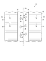
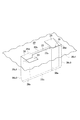
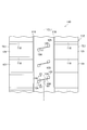
図1を参照すると、タイヤ10のトレッド部12の表面の一部が平坦面上に展開された状態で概略的に示されている。 (First embodiment)
Referring to FIG. 1, a part of the surface of thetread portion 12 of the tire 10 is schematically shown in a state of being developed on a flat surface.
図1を参照すると、タイヤ10のトレッド部12の表面の一部が平坦面上に展開された状態で概略的に示されている。 (First embodiment)
Referring to FIG. 1, a part of the surface of the
タイヤ10は、その適用対象を問わないが、典型的には車両系建設機械のような大型車両に用いられる空気入りタイヤからなる。
The tire 10 is not limited to the application target, but is typically a pneumatic tire used for a large vehicle such as a vehicle construction machine.
タイヤ10のトレッド部12は任意のパターン(トレッドパターン)を備える。図1に示すトレッドパターンは、タイヤ周方向(図1において上下方向)へ伸びる一対の周方向溝16と、タイヤ幅方向(図1において左右方向)へ伸びる複数の幅方向溝18とを備える。両周方向溝16は、タイヤ10の赤道面CLの両側に位置する。また、複数の幅方向溝18は、各周方向溝16と各トレッド端TEとの間において、タイヤ周方向へ互いに等間隔をおいて配置されている。各幅方向溝18はその一端において各周方向溝16に連通し、また、その他端が各トレッド端TEで終わっている。
The tread portion 12 of the tire 10 has an arbitrary pattern (tread pattern). The tread pattern shown in FIG. 1 includes a pair of circumferential grooves 16 extending in the tire circumferential direction (up and down direction in FIG. 1) and a plurality of width direction grooves 18 extending in the tire width direction (left and right direction in FIG. 1). Both circumferential grooves 16 are located on both sides of the equatorial plane CL of the tire 10. Further, the plurality of widthwise grooves 18 are arranged at equal intervals in the tire circumferential direction between each circumferential groove 16 and each tread end TE. Each widthwise groove 18 communicates with each circumferential groove 16 at one end, and the other end ends at each tread end TE.
前記トレッドパターンは、両周方向溝16によりこれらの間に区画されたタイヤ周方向へ伸びる中央陸部20と、タイヤ周方向に互いに隣接する2つの幅方向溝18によりこれらの間に区画されたブロック状陸部21とを備える。中央陸部20及びブロック状陸部21の表面が、実質的に、タイヤ10の踏面をそれぞれ規定する。
The tread pattern is defined between the central land portion 20 extending in the tire circumferential direction defined between the circumferential grooves 16 and the two widthwise grooves 18 adjacent to each other in the tire circumferential direction. And a block-shaped land portion 21. The surfaces of the central land portion 20 and the block-shaped land portion 21 substantially define the tread surface of the tire 10, respectively.
トレッド部12の前記トレッドパターンは、いわゆるリブ型パターン、ラグ型パターン、ブロック型パターン等からなるものであってもよい。また、幅方向溝18は、例えば、これが前記幅方向に対してこれと交差する方向へ伸びあるいは互いに異なる幅寸法を有するものであってもよい。
The tread pattern of the tread portion 12 may be a so-called rib pattern, rug pattern, block pattern, or the like. Moreover, the width direction groove | channel 18 may extend in the direction which cross | intersects this with respect to the said width direction, or may have a mutually different width dimension, for example.
タイヤ10は、これを装着した前記車両の作業又は走行に伴ってそのトレッド部12に生じる熱を放出するためにトレッド部12に設けられた、前記踏面を規定する中央陸部20の表面に開放する少なくとも1つの、図示の例においては複数の空気受入溝22と、各空気受入溝22に連通する一組の空気導入溝24及び空気案内溝(空気案内部)26と、もう一組の他の空気導入溝28及び他の空気案内溝(空気案内部)30とを備える。これらの溝22~30は、図示の例に代えて、各ブロック状陸部21に設けてもよい。
The tire 10 is opened to the surface of the central land portion 20 that defines the tread surface provided in the tread portion 12 to release heat generated in the tread portion 12 in accordance with the work or running of the vehicle on which the tire 10 is mounted. In the illustrated example, at least one of the plurality of air receiving grooves 22, a set of air introducing grooves 24 and air guiding grooves (air guiding portions) 26 communicating with each of the air receiving grooves 22, and another set of others. Air introduction groove 28 and another air guide groove (air guide part) 30. These grooves 22 to 30 may be provided in each block-shaped land portion 21 instead of the illustrated example.
空気導入溝24、28は、それぞれ、前記車両がその作業又は走行のためにタイヤ10が一方向に回転するとき、前記一方向における前方及び後方に位置するように設けられている。空気導入溝24は、タイヤ10が前記一方向に回転するとき空気導入溝24に流入する空気(大気)を空気受入溝22に導入する働きをなし、空気受入溝22は、これに導入された空気を受け入れる働きをなし、空気案内溝26は、空気受入溝22に導入された空気を、空気受入溝22の溝底に向けて案内する働きをなす。このとき、他の空気導入溝28は、空気受入溝22内を流動した後の空気の流出路として働く。
The air introduction grooves 24 and 28 are provided so as to be positioned forward and rearward in the one direction when the tire 10 rotates in one direction for the vehicle to work or travel, respectively. The air introduction groove 24 functions to introduce air (atmosphere) flowing into the air introduction groove 24 into the air reception groove 22 when the tire 10 rotates in the one direction, and the air reception groove 22 is introduced into this. The air guide groove 26 serves to receive air and guides the air introduced into the air receiving groove 22 toward the groove bottom of the air receiving groove 22. At this time, the other air introduction groove 28 functions as an air outflow path after flowing in the air receiving groove 22.
同様に、タイヤ10が反対方向に回転するとき、他の空気導入溝28がこれに流入する空気を空気受入溝22に導入する働きをなし、空気案内溝30は、空気受入溝22に導入された空気を空気受入溝22の溝底に向けて案内する働きをなす。このとき、空気導入溝24は、空気受入溝22内を流動した後の空気の流出路として働く。ここにおいて、空気受入溝22を流動する空気が、流動の間に、トレッド部12から熱を奪う働きをなす。
Similarly, when the tire 10 rotates in the opposite direction, another air introduction groove 28 serves to introduce the air flowing into the air reception groove 22, and the air guide groove 30 is introduced into the air reception groove 22. The air is guided toward the groove bottom of the air receiving groove 22. At this time, the air introduction groove 24 functions as an air outflow path after flowing in the air receiving groove 22. Here, the air flowing through the air receiving groove 22 functions to take heat away from the tread portion 12 during the flow.
複数の空気受入溝22は、それぞれ、トレッド部12を構成する中央陸部20の表面(タイヤ10の踏面)に開放している。図示の例では、複数の空気受入溝22は、タイヤ周方向に互いに等間隔をおいて互いに平行に配置されている。これに代えて、複数の空気受入溝22を互いに異なる間隔をおいて、あるいは、互いに非平行であるように配置することが可能である。
Each of the plurality of air receiving grooves 22 is open to the surface of the central land portion 20 constituting the tread portion 12 (the tread surface of the tire 10). In the illustrated example, the plurality of air receiving grooves 22 are arranged in parallel to each other at equal intervals in the tire circumferential direction. Alternatively, the plurality of air receiving grooves 22 can be arranged at different intervals or non-parallel to each other.
空気受入溝22は、タイヤ周方向に対して該タイヤ周方向と交差する方向に伸びている。すなわち、タイヤ周方向に対してこれと非平行に伸びている。交差角度θは、0°<θ≦90°の範囲内、好ましくは0°<θ≦60°の範囲内にあるように設定する。また、図示の空気受入溝22は、その長手方向における一端及び他端が中央陸部20内にある。空気受入溝22は、中央陸部20内を伸びかつ中央陸部20内において終端している。空気受入溝22は、その長手方向における両端の双方又は一方において、両周方向溝16の双方又は一方と連通するものであってもよいが、中央陸部20の剛性の低下を考慮して、図示の例のように非連通とすることが望ましい。
The air receiving groove 22 extends in a direction intersecting the tire circumferential direction with respect to the tire circumferential direction. That is, it extends non-parallel to the tire circumferential direction. The crossing angle θ is set in a range of 0 ° <θ ≦ 90 °, and preferably in a range of 0 ° <θ ≦ 60 °. In addition, the air receiving groove 22 shown in the figure has one end and the other end in the longitudinal direction in the central land portion 20. The air receiving groove 22 extends in the central land portion 20 and terminates in the central land portion 20. The air receiving groove 22 may be communicated with both or one of the circumferential grooves 16 at both or one of the both ends in the longitudinal direction thereof, but considering the decrease in rigidity of the central land portion 20, It is desirable not to communicate as in the illustrated example.
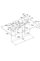
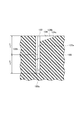
図2に示すように、各空気受入溝22は、U字形の横断面形状とこれを規定する互いに相対する一対の平坦面からなる溝壁面22a、22b及びこれらの両溝壁面22a、22bに連なる、平坦面からなる溝底22cとを有する。空気受入溝22は、図示の例に代えて、例えば、V字形の横断面形状を有するものとすることができる。前記V字形の横断面形状を有する空気受入溝では、互いに相対する一対の溝壁面はそれぞれ平坦な面からなり、また、溝底は両溝壁面の交差部からなり、直線状を呈する。
As shown in FIG. 2, each air receiving groove 22 is connected to a groove wall surface 22a, 22b composed of a U-shaped cross-sectional shape and a pair of opposed flat surfaces defining the U-shaped cross section, and both the groove wall surfaces 22a, 22b. And a groove bottom 22c made of a flat surface. The air receiving groove 22 may have, for example, a V-shaped cross section instead of the illustrated example. In the air receiving groove having the V-shaped cross-sectional shape, the pair of groove wall surfaces facing each other is a flat surface, and the groove bottom is a crossing portion of both groove wall surfaces and has a straight line shape.
各空気受入溝22の溝幅W及びその溝深さD(図2参照)の大きさは、空気受入溝22を設けることによって生じるトレッド部12の剛性の低下、具体的には中央陸部20の剛性の低下を制限するため、W<Dの関係を満たすように設定される。空気受入溝22は、その一例として、交差角度θ=30°、溝幅W=10mm、溝深さD=100mm及びその長手方向の長さL(図2参照)=200mmを有する。
The size of the groove width W and the groove depth D (see FIG. 2) of each air receiving groove 22 is reduced in rigidity of the tread portion 12 caused by providing the air receiving groove 22, specifically, the central land portion 20. Is set to satisfy the relationship of W <D. As an example, the air receiving groove 22 has an intersection angle θ = 30 °, a groove width W = 10 mm, a groove depth D = 100 mm, and a length L in the longitudinal direction (see FIG. 2) = 200 mm.
二組の空気導入溝及び空気案内溝である一組の空気導入溝24及び空気案内溝26と、もう一組の他の空気導入溝28及び空気案内溝30とは、それぞれ前記空気受入溝の長手方向に互いに間隔をおいて配置されており、図2に図示する例では、それぞれ、空気受入溝22の長手方向における両端部に配置されている。これに代えて、前記二組のうちの一方(例えば一組の空気導入溝24及び空気案内溝26)のみを空気受入溝22の両端部のいずれか一方に設けることができる。あるいは、また、前記二組のうちの一方(例えば一組の空気導入溝24及び空気案内溝26)のみを空気受入溝22の一端部に設け、かつ、空気受入溝22の他端部に他の空気導入溝28のみを設けることができる。
Two sets of air introduction grooves and air guide grooves, which are one set of air introduction groove 24 and air guide groove 26, and another set of other air introduction grooves 28 and air guide grooves 30 are respectively the air receiving grooves. In the example illustrated in FIG. 2, the air receiving grooves 22 are disposed at both ends in the longitudinal direction. Instead of this, only one of the two sets (for example, one set of the air introduction groove 24 and the air guide groove 26) can be provided on either one of the both ends of the air receiving groove 22. Alternatively, only one of the two sets (for example, one set of air introduction groove 24 and air guide groove 26) is provided at one end of the air receiving groove 22, and the other is provided at the other end of the air receiving groove 22. Only the air introduction groove 28 can be provided.
図2及び図3に示すように、空気導入溝24、28は、それぞれ、中央陸部20の表面(踏面)に開放している。これにより、タイヤ10の周囲からの空気導入溝24、28内への空気の取入れが可能とされている。また、空気導入溝24、28は、それぞれ、任意の方向、好ましくは、タイヤ周方向に伸びている。これにより、空気導入溝24、28への空気の流入の円滑化を図ることができる。さらに、空気導入溝24、28は、それぞれ、空気受入溝22の溝幅W(図2)を規定する両溝壁面22a、22bのうちの一方22a及び他方22bにおいて、空気受入溝22に連通し該空気受入溝に開口している。これにより、タイヤ10の前記一方向への回転時及びこれと反対方向への回転時おける前記空気の取入れと、空気受入溝22への空気の導入とが可能とされている。
2 and 3, the air introduction grooves 24 and 28 are open to the surface (tread surface) of the central land portion 20, respectively. As a result, air can be taken into the air introduction grooves 24 and 28 from the periphery of the tire 10. The air introduction grooves 24 and 28 each extend in an arbitrary direction, preferably in the tire circumferential direction. Thereby, smooth inflow of the air into the air introduction grooves 24 and 28 can be achieved. Further, the air introduction grooves 24 and 28 communicate with the air reception groove 22 at one of the groove wall surfaces 22a and 22b defining the groove width W (FIG. 2) of the air reception groove 22 and the other 22b, respectively. The air receiving groove opens. Accordingly, the air can be taken in and the air can be introduced into the air receiving groove 22 when the tire 10 is rotated in the one direction and in the opposite direction.
一方の空気導入溝24は、U字形の横断面形状とこれを規定する互いに相対する一対の平坦面からなる溝壁面24a、24b及びこれらの両溝壁面に連なる、平坦面からなる溝底24cとを有し、溝底24cは空気受入溝22の一方の溝壁面22aと交差している。他方の空気導入溝28も、空気導入溝24におけると同様のU字形の横断面形状とこれを規定する互いに相対する一対の平坦面からなる溝壁面28a、28b及びこれらの両溝壁面28a、28bに連なる、平坦面からなる溝底28cとを有し、溝底28cは空気受入溝22の他方の溝壁面22bと交差している。各空気導入溝24、28は、図示の例に代えて、例えば、V字形の横断面形状を有するものとすることができる。前記V字形の横断面形状を有する各空気導入溝にあっては、互いに相対する一対の溝壁面がそれぞれ平坦な面からなり、また、溝底は両溝壁面の交差部からなり、直線状を呈する。
One of the air introduction grooves 24 includes a U-shaped cross-sectional shape, a pair of opposed flat surfaces that define the U-shaped cross section, and groove surfaces 24a and 24b that are opposed to each other, and a groove bottom 24c that is formed of a flat surface that is continuous with both of these groove walls. The groove bottom 24 c intersects one groove wall surface 22 a of the air receiving groove 22. The other air introduction groove 28 also has a U-shaped cross-sectional shape similar to that of the air introduction groove 24 and a pair of opposed flat surfaces that define the U-shaped transverse wall surface 28a, 28b, and both of these groove wall surfaces 28a, 28b. The groove bottom 28 c is a flat surface, and the groove bottom 28 c intersects the other groove wall surface 22 b of the air receiving groove 22. Each of the air introduction grooves 24 and 28 may have, for example, a V-shaped cross section instead of the illustrated example. In each air introduction groove having the V-shaped cross-sectional shape, a pair of groove wall surfaces facing each other is a flat surface, and the groove bottom is an intersection of both groove wall surfaces, and has a linear shape. Present.
空気導入溝24の溝底24c及び空気導入溝28の溝底28cは、それぞれ、中央陸部20の表面(踏面)からタイヤ径方向内側に向けて傾斜する傾斜面からなる。このため、空気受入溝22に向かうにつれて溝深さが次第に深くなり、また、両溝壁面24a、24b及び両溝壁面28a、28bは直角三角形状を呈する。溝底24c及び溝底28cは、それぞれ、非傾斜状態で伸びるものとしてもよいが、これを前記傾斜面とするときは、溝底24cを非傾斜状態にする場合と比べて、空気導入溝24から空気案内溝26に至る空気に、空気受入溝22の溝底に向かうように強制するより大きい推進動力を与えることができる。
The groove bottom 24c of the air introduction groove 24 and the groove bottom 28c of the air introduction groove 28 are respectively inclined surfaces inclined from the surface (tread surface) of the central land portion 20 toward the inside in the tire radial direction. For this reason, the groove depth gradually increases toward the air receiving groove 22, and both the groove wall surfaces 24a and 24b and the both groove wall surfaces 28a and 28b have a right triangle shape. Each of the groove bottom 24c and the groove bottom 28c may extend in a non-inclined state. However, when the groove bottom 24c and the groove bottom 28c are formed as the inclined surface, the air introduction groove 24 is compared with the case where the groove bottom 24c is in a non-inclined state. To the air guide groove 26 can be given more propulsive power forcing it toward the groove bottom of the air receiving groove 22.
空気導入溝24、28の前記傾斜面の傾斜角度すなわち溝底24c、28cの中央陸部20の表面(踏面)に対する傾斜角度α(図2)は、45°以下、好ましくは20°~30°の範囲にあることが望ましい。これは、空気導入溝24、28から空気受入溝22への前記空気の流量が傾斜角度αの増大に伴って増大するが、傾斜角度αが45°を超えると、空気受入溝22の近傍において前記空気の流れが溝底24c、28cから剥離し易くなり、前記空気の流量が減少することによる。
The inclination angle α of the inclined surfaces of the air introduction grooves 24, 28, that is, the inclination angle α (FIG. 2) with respect to the surface (tread surface) of the central land portion 20 of the groove bottoms 24c, 28c is 45 ° or less, preferably 20 ° -30 °. It is desirable to be in the range. This is because the flow rate of the air from the air introduction grooves 24 and 28 to the air receiving groove 22 increases as the inclination angle α increases, but in the vicinity of the air receiving groove 22 when the inclination angle α exceeds 45 °. This is because the air flow is easily separated from the groove bottoms 24c and 28c, and the flow rate of the air is reduced.
また、空気案内溝26は、U字形の横断面形状とこれを規定する互いに相対する一対の平坦面からなる溝壁面26a、26b及びこれらの両溝壁面に連なる平坦面からなる溝底26cとを有する。他の空気案内溝30も、同様に、空気案内溝26と同様のU字形の横断面形状とこれを規定する互いに相対する一対の平坦面からなる溝壁面30a、30b及びこれらの両溝壁面に連なる、平坦面からなる溝底30cとを有する。各空気案内溝26、30は、図示の例に代えて、例えば、V字形の横断面形状を有するものとすることができる(図7(c)参照)。前記V字形の横断面形状を有する各空気案内溝にあっては、互いに相対する一対の溝壁面がそれぞれ平坦な面からなり、また、溝底が両溝壁面の交差部からなり、直線状を呈する。
The air guide groove 26 has a U-shaped cross-sectional shape, a groove wall surface 26a, 26b composed of a pair of opposed flat surfaces defining the U-shaped cross section, and a groove bottom 26c composed of a flat surface connected to both the groove wall surfaces. Have. Similarly, the other air guide grooves 30 are formed on the groove wall surfaces 30a and 30b formed of a U-shaped cross-sectional shape similar to the air guide groove 26 and a pair of opposed flat surfaces that define the U-shaped cross section, and both the groove wall surfaces. And a groove bottom 30c formed of a flat surface. Each of the air guide grooves 26 and 30 may have, for example, a V-shaped cross section instead of the illustrated example (see FIG. 7C). In each air guide groove having the V-shaped cross-sectional shape, a pair of groove wall surfaces facing each other is a flat surface, and the groove bottom is an intersection of both groove wall surfaces. Present.
空気案内溝26、30は、それぞれ、空気受入溝22の周方向他方側の溝壁面22b及び一方側の溝壁面22aに開放しており、また、タイヤ径方向へ伸長している。そして空気案内溝26、30は、空気受入溝22の他方の溝壁面22bまたは一方の溝壁面22aに交差する位置において空気受入溝22の溝長手方向中央位置に対して外向きである溝壁面(空気案内面)26b,30bを有する。このことから、空気受入溝22に導入される前記空気は、空気案内溝26、30が形成される位置において空気受入溝22のみが形成されている場合よりも流体抵抗が小さくなり、空気受入溝22の溝底22cに向けて案内することができる。ここで空気受入溝22の溝長手方向中央位置とは、例えば空気受入溝22の長手方向の中心から、空気受入溝22の長手方向長さLの±5%の範囲をいう。
The air guide grooves 26 and 30 are open to the groove wall surface 22b and the groove wall surface 22a on the other side in the circumferential direction of the air receiving groove 22, respectively, and extend in the tire radial direction. The air guide grooves 26 and 30 are groove wall surfaces that are outward with respect to the center position in the longitudinal direction of the air receiving groove 22 at a position intersecting the other groove wall surface 22b of the air receiving groove 22 or the one groove wall surface 22a. Air guide surfaces) 26b and 30b. Therefore, the air introduced into the air receiving groove 22 has a smaller fluid resistance than the case where only the air receiving groove 22 is formed at the position where the air guide grooves 26 and 30 are formed, and the air receiving groove 22 It can guide toward the groove bottom 22c of 22. Here, the center position in the longitudinal direction of the air receiving groove 22 refers to, for example, a range of ± 5% of the longitudinal length L of the air receiving groove 22 from the center in the longitudinal direction of the air receiving groove 22.
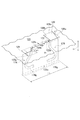
図2及び図3を参照すると、空気案内溝26は、タイヤ径方向における一端(図上おいて外側端)26dと他端(図上において内側端)26eとを有する。空気案内溝26の一端26d及び他端26eは、それぞれ、空気導入溝24の溝底24cと空気受入溝22の一方の溝壁面22aとの交差位置P1(図3)よりもタイヤ径方向外側及び空気受入溝22の溝深さの半分の位置P2(図3)よりもタイヤ径方向内側にある。図示の例において、空気案内溝26は、その一端26dが中央陸部20の表面(踏面)に開放しており、他端26eが空気受入溝22の溝底22cと同じ溝深さである。
2 and 3, the air guide groove 26 has one end (outer end in the figure) 26d and the other end (inner end in the figure) 26e in the tire radial direction. One end 26d and the other end 26e of the air guide groove 26 are respectively located on the outer side in the tire radial direction from the intersection position P1 (FIG. 3) between the groove bottom 24c of the air introduction groove 24 and one groove wall surface 22a of the air receiving groove 22. It is on the inner side in the tire radial direction from the position P2 (FIG. 3) which is half the groove depth of the air receiving groove 22. In the illustrated example, one end 26 d of the air guide groove 26 is open to the surface (tread surface) of the central land portion 20, and the other end 26 e has the same groove depth as the groove bottom 22 c of the air receiving groove 22.
同様に、空気案内溝30も、タイヤ径方向における一端(外側端)30dと他端(内側端)30eとを有する(図2)。また、空気案内溝30の一端30d及び他端30e(図2)も、それぞれ、空気導入溝28の溝底28cと空気受入溝22の他方の溝壁面22bとの交差位置(P1)よりもタイヤ径方向外側及び空気受入溝22の溝深さの半分の位置(P2)よりもタイヤ径方向内側にある。図示の例において、空気案内溝30は、その一端30dが中央陸部20の表面(踏面)に開放しており、他端30eが空気受入溝22の溝底22cと同じ溝深さである。
Similarly, the air guide groove 30 also has one end (outer end) 30d and the other end (inner end) 30e in the tire radial direction (FIG. 2). The one end 30d and the other end 30e (FIG. 2) of the air guide groove 30 are also more tires than the intersection position (P1) between the groove bottom 28c of the air introduction groove 28 and the other groove wall surface 22b of the air receiving groove 22, respectively. It exists in the tire radial direction inner side than the position (P2) of the radial direction outer side and the groove depth of the air receiving groove 22 half. In the illustrated example, the air guide groove 30 has one end 30 d opened to the surface (tread surface) of the central land portion 20, and the other end 30 e has the same groove depth as the groove bottom 22 c of the air receiving groove 22.
空気案内溝26,30の一端26d、30dを位置P1より前記タイヤ径方向外側におくことにより、空気導入溝24、28の溝底24c、28cに沿って空気受入溝22に導入される空気AR(図3)が空気案内溝26、30内に流入可能とすることができる。また、空気案内溝26,30の他端26e、30eを位置P2よりも前記タイヤ径方向内側におくことにより、空気案内溝26、30によって案内される空気ARを、空気受入溝22の溝底22cにより近い位置で解放する。これにより、空気案内溝26、30は、空気受入溝22の溝底22c又はその近傍に空気ARを強制的に送り込むことができる。
The air AR introduced into the air receiving groove 22 along the groove bottoms 24c and 28c of the air introduction grooves 24 and 28 by placing one ends 26d and 30d of the air guide grooves 26 and 30 on the outer side in the tire radial direction from the position P1. (FIG. 3) can flow into the air guide grooves 26, 30. Further, by placing the other ends 26e, 30e of the air guide grooves 26, 30 on the inner side in the tire radial direction from the position P2, the air AR guided by the air guide grooves 26, 30 is allowed to flow into the groove bottom of the air receiving groove 22. Release at a position closer to 22c. Thereby, the air guide grooves 26 and 30 can forcibly send the air AR to the groove bottom 22c of the air receiving groove 22 or the vicinity thereof.
また、空気案内溝26、30は、それぞれ、空気導入溝24、28に対してタイヤ周方向に対向している。図示の例では、空気導入溝24,28と空気案内溝26、30とは、それぞれ、空気受入溝22の長手方向X(図2)に関して同じ大きさの溝幅を有し、前記溝幅の全部において互いに対向している。しかし、これに限らず、空気導入溝24,28と空気案内溝26、30とは、空気受入溝22の長手方向Xに関して、少なくとも部分的に対向する関係又は重なり合う関係にあればよい(図7(a)、(b)参照)。これにより、空気導入溝24、28からの空気ARが、空気受入溝22を横断して、空気案内溝内26,30に到達することができる。
The air guide grooves 26 and 30 are opposed to the air introduction grooves 24 and 28 in the tire circumferential direction, respectively. In the illustrated example, the air introduction grooves 24 and 28 and the air guide grooves 26 and 30 have the same groove width in the longitudinal direction X (FIG. 2) of the air receiving groove 22, respectively. All are facing each other. However, the present invention is not limited to this, and the air introduction grooves 24 and 28 and the air guide grooves 26 and 30 may be at least partially opposed or overlapped with each other in the longitudinal direction X of the air receiving groove 22 (FIG. 7). (Refer to (a) and (b)). Thereby, the air AR from the air introduction grooves 24 and 28 can cross the air receiving groove 22 and reach the air guide grooves 26 and 30.
前記したところにより、空気ARは空気受入溝22内においてその溝底22c上又はその近傍をその長手方向Xへ流動することが可能となり、これがトレッド部12の深部の冷却及びこれに伴う該深部の温度低下に寄与する。
As described above, the air AR can flow in the longitudinal direction X on or near the groove bottom 22c in the air receiving groove 22, and this causes cooling of the deep portion of the tread portion 12 and the accompanying deep portion of the deep portion. Contributes to temperature reduction.
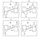
タイヤの中央陸部20を部分的に投影した図7(a)~(d)を参照すると、図7(a)の例においては、空気導入溝24、28が空気案内溝26、30より大きい溝幅を有し、このために空気導入溝24、28と空気案内溝26、30とが空気受入溝22の長手方向X(図2)に関して部分的に対向している。図7(b)の例においては、空気導入溝24、28が空気案内溝26、30より大きい溝幅を有することに加えて、空気案内溝26、30が、それぞれ、伸長方向Xに関して、空気受入溝22の一端から他端に向けて間隔をおいた位置及び他端から一端に向けて間隔をおいた位置に置かれている。このため、空気導入溝24、28と空気案内溝26、30とが長手方向Xに関して部分的に対向している。また、図7(c)及び図7(d)に示す例においては、空気導入溝24,28と空気案内溝26、30とが、それぞれ、空気受入溝22の長手方向Xに関して、同じ大きさの溝幅を有し、これらの溝幅の全部において対向している。
7A to 7D in which the central land portion 20 of the tire is partially projected, the air introduction grooves 24 and 28 are larger than the air guide grooves 26 and 30 in the example of FIG. 7A. The air introduction grooves 24 and 28 and the air guide grooves 26 and 30 are partially opposed to each other with respect to the longitudinal direction X of the air receiving groove 22 (FIG. 2). In the example of FIG. 7B, in addition to the air introduction grooves 24 and 28 having a groove width larger than the air guide grooves 26 and 30, the air guide grooves 26 and 30 The receiving groove 22 is placed at a position spaced from one end to the other end and at a position spaced from the other end toward the one end. For this reason, the air introduction grooves 24 and 28 and the air guide grooves 26 and 30 are partially opposed in the longitudinal direction X. In the example shown in FIGS. 7C and 7D, the air introduction grooves 24 and 28 and the air guide grooves 26 and 30 have the same size with respect to the longitudinal direction X of the air receiving groove 22, respectively. These groove widths are opposed to each other in all of these groove widths.
また、図7(a)~(d)に示すように、空気導入溝24、28の中央陸部20の表面(踏面)における開放面形状及び空気案内溝26,30の一端26d、30d(図1参照)の平面形状すなわち中央陸部20の表面(踏面)における開放面形状は、先の例で示した矩形と異なる任意の形状とすることができる。図7(a)~(d)において、空気導入溝24、28の前記開放面形状は、台形とされている。また、空気案内溝26、30の前記開放面形状は、台形(図7(a)、(b))、三角形(図7(c))、円弧形(図7(d))とされている。なお、図7(d)に示す例にあっては、各空気案内溝26、30の両溝壁面(26a,26b)、(30a,30b)及び溝底(26c)、(30c)が、全体として円筒面の一部を構成し、両溝壁面及び溝底が前記円筒面の一部を構成する連続した3つの円弧面からなる。また、図7(a)~(d)に示す各例に関し、空気受入溝22の長手方向X(図2)における両端のそれぞれにおいて、空気受入溝22に対する各空気導入溝24、28の交差角度βが鋭角をなしている。交差角度βは、これを鋭角とすることに代えて、90度(図2参照)に設定し、あるいは鈍角(図1参照)に設定することが可能である。但し、交差角度βを鋭角に設定すると、他の角度に設定する場合と比べて、空気導入溝24,28を流れる空気が交差角度βを規定する箇所に集まりやすく、その後、空気受入溝22内をその溝底22cに向けて流れやすい。
Further, as shown in FIGS. 7A to 7D, the open surface shape of the air introduction grooves 24 and 28 on the surface (tread surface) of the central land portion 20 and the one ends 26d and 30d of the air guide grooves 26 and 30 (see FIG. 7). 1), that is, the open surface shape on the surface (tread surface) of the central land portion 20 can be an arbitrary shape different from the rectangle shown in the previous example. 7A to 7D, the open surface shape of the air introduction grooves 24 and 28 is a trapezoid. The open surface shapes of the air guide grooves 26 and 30 are trapezoid (FIGS. 7A and 7B), a triangle (FIG. 7C), and an arc shape (FIG. 7D). Yes. In the example shown in FIG. 7D, the groove wall surfaces (26a, 26b), (30a, 30b) and the groove bottoms (26c), (30c) of the air guide grooves 26, 30 are entirely formed. As a part of the cylindrical surface, both the groove wall surface and the groove bottom are composed of three continuous circular arc surfaces constituting a part of the cylindrical surface. 7A to 7D, the crossing angles of the air introduction grooves 24 and 28 with respect to the air receiving groove 22 at both ends in the longitudinal direction X of the air receiving groove 22 (FIG. 2). β forms an acute angle. The crossing angle β can be set to 90 degrees (see FIG. 2) or an obtuse angle (see FIG. 1) instead of making it an acute angle. However, when the crossing angle β is set to an acute angle, the air flowing through the air introduction grooves 24 and 28 is likely to gather at a location that defines the crossing angle β, and then in the air receiving groove 22 as compared with the case where the other angle is set. Tends to flow toward the groove bottom 22c.
さらに、空気案内溝26、30の溝底26c、30cについて、その全部が空気受入溝22の溝壁面22a、22bと平行にタイヤ径方向へ伸びる平坦面からなるものとする先の例(図2)に代えて、次のように設定することができる(図4、図5及び図8参照)。
Further, with respect to the groove bottoms 26c and 30c of the air guide grooves 26 and 30, the previous example in which all of them are formed of flat surfaces extending in the tire radial direction in parallel with the groove wall surfaces 22a and 22b of the air receiving groove 22 (FIG. 2). ) Can be set as follows (see FIGS. 4, 5 and 8).
図4に示す例では、空気案内溝26、30の溝底が平坦面26c1、30c1と傾斜面26c2、30c2とからなる。平坦面26c1、30c1は、空気案内溝26、30の一端26d、30dから空気受入溝22の溝壁面22a、22bと平行にタイヤ径方向内側へ伸びている。また、傾斜面26c2、30c2は、平坦面26c1、30c1に角度をなして連なり、空気案内溝26、30の他端26e、30eに至る。
In the example shown in FIG. 4, the groove bottoms of the air guide grooves 26 and 30 are formed of flat surfaces 26c1 and 30c1 and inclined surfaces 26c2 and 30c2. The flat surfaces 26c1 and 30c1 extend inward in the tire radial direction in parallel with the groove wall surfaces 22a and 22b of the air receiving groove 22 from one ends 26d and 30d of the air guide grooves 26 and 30. The inclined surfaces 26c2 and 30c2 are connected to the flat surfaces 26c1 and 30c1 at an angle and reach the other ends 26e and 30e of the air guide grooves 26 and 30, respectively.
図5に示す例は、図4に示す傾斜面26c2、30c2が、これに代えて、凹状の曲面26c3、30c3とされている。凹状の曲面26c3、30c3は、それぞれ、空気受入溝22の両溝壁面22a、22bに相対している。図4及び図5に示すこれらの例によれば、空気案内溝26、30の体積をより小さいものとすることができる。このため、前記空気案内溝を設けることによる中央陸部20の剛性の低下を制限することができる。
In the example shown in FIG. 5, the inclined surfaces 26c2, 30c2 shown in FIG. 4 are replaced with concave curved surfaces 26c3, 30c3. The concave curved surfaces 26c3 and 30c3 are opposed to both the groove wall surfaces 22a and 22b of the air receiving groove 22, respectively. According to these examples shown in FIGS. 4 and 5, the volume of the air guide grooves 26 and 30 can be made smaller. For this reason, the fall of the rigidity of the central land part 20 by providing the said air guide groove can be restrict | limited.
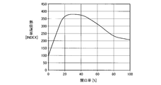
ところで、図2、図4及び図5に示す例では、前記したように、空気案内溝26、30の一端26d、30dが中央陸部20の表面(踏面)に開放している。これは、トレッド部12の剛性を低下させる要因であり、また、トレッド部12とこれに冷却作用を及ぼす空気ARとの間の熱伝達率を変化させる要因でもある。このことから、タイヤ10の前記踏面上における空気導入溝24及び他の空気導入溝28の正投影面積の和(A)に対する空気案内溝26及び他の空気案内溝30の正投影面積の和(B)の比である開口率(B/A)をどのように設定するかは重要である。
By the way, in the example shown in FIGS. 2, 4 and 5, as described above, the one ends 26 d and 30 d of the air guide grooves 26 and 30 are open to the surface (tread) of the central land portion 20. This is a factor that decreases the rigidity of the tread portion 12 and also a factor that changes the heat transfer coefficient between the tread portion 12 and the air AR that exerts a cooling action on the tread portion 12. From this, the sum of the orthographic projection areas of the air guide groove 26 and the other air guide groove 30 with respect to the sum (A) of the orthographic projection areas of the air introduction groove 24 and the other air introduction groove 28 on the tread surface of the tire 10 ( It is important how to set the aperture ratio (B / A) that is the ratio of B).
図6に、実験により得られた開口率(B/A)と前記熱伝導率との関係をグラフで示す。これによれば、開口率(B/A)が30~40%において前記熱伝達率がほぼ最大値を示す。このことから、開口率(B/A)は、これを50%以下とすることが望ましい。
FIG. 6 is a graph showing the relationship between the aperture ratio (B / A) obtained by the experiment and the thermal conductivity. According to this, when the aperture ratio (B / A) is 30 to 40%, the heat transfer coefficient is almost the maximum value. Therefore, it is desirable that the aperture ratio (B / A) is 50% or less.
図8に示すように、空気案内溝26、30は、これらを、空気受入溝22の両溝壁面22a、22bにそれぞれ相対する凹状の曲面からなる凹部である溝底26c、30cを有するものとすることができる。空気案内溝26、30は、溝底26c、30cにそれぞれ連なる両溝壁面26a,26b、30a,30bを有し、両溝壁面26a,26b、30a,30bは、それぞれ、弓張月の形状を呈する。空気案内溝26,30の一端26d、30d及び他端26e、30eはそれぞれ中央陸部20の表面(踏面)20と空気受入溝22の溝底22cとの間に位置する。これらの案内溝26、30にあっても、その一端26d、30dが、空気導入溝24、28の溝底24c、28cと空気受入溝22の溝壁面22b、22aとの交差位置(P1)よりタイヤ径方向外側にあり、また、その他端26e、30eが空気受入溝22の溝深さの半分の位置(P2)よりもタイヤ径方向内側にある。
As shown in FIG. 8, the air guide grooves 26 and 30 have groove bottoms 26 c and 30 c which are concave portions formed of concave curved surfaces respectively opposed to both groove wall surfaces 22 a and 22 b of the air receiving groove 22. can do. The air guide grooves 26, 30 have both groove wall surfaces 26a, 26b, 30a, 30b respectively connected to the groove bottoms 26c, 30c, and the both groove wall surfaces 26a, 26b, 30a, 30b each have the shape of an arched moon. . One end 26d, 30d and the other end 26e, 30e of the air guide grooves 26, 30 are located between the surface (tread surface) 20 of the central land portion 20 and the groove bottom 22c of the air receiving groove 22, respectively. Even in the guide grooves 26 and 30, one end 26 d and 30 d is from the intersection position (P 1) between the groove bottoms 24 c and 28 c of the air introduction grooves 24 and 28 and the groove wall surfaces 22 b and 22 a of the air receiving groove 22. The other ends 26e and 30e are located on the inner side in the tire radial direction from the position (P2) that is half the groove depth of the air receiving groove 22.
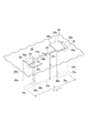
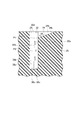
(第2実施形態)
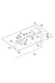
第2実施形態を説明する。図9では、第2実施形態のタイヤ110のトレッド部112の表面の一部が平坦面上に展開された状態で概略的に示されている。図10では、第2実施形態のタイヤ110の踏面の部分斜視図が示されている。図11では、図9の線XI-XIの断面図が示されている。 (Second Embodiment)
A second embodiment will be described. In FIG. 9, a part of the surface of thetread portion 112 of the tire 110 of the second embodiment is schematically shown in a state of being developed on a flat surface. In FIG. 10, the fragmentary perspective view of the tread surface of the tire 110 of 2nd Embodiment is shown. FIG. 11 shows a cross-sectional view taken along line XI-XI in FIG.
第2実施形態を説明する。図9では、第2実施形態のタイヤ110のトレッド部112の表面の一部が平坦面上に展開された状態で概略的に示されている。図10では、第2実施形態のタイヤ110の踏面の部分斜視図が示されている。図11では、図9の線XI-XIの断面図が示されている。 (Second Embodiment)
A second embodiment will be described. In FIG. 9, a part of the surface of the
タイヤ110は、その適用対象を問わないが、典型的には車両系建設機械のような大型車両に用いられる空気入りタイヤからなる。
The tire 110 is not limited to the application target, but is typically a pneumatic tire used for a large vehicle such as a vehicle construction machine.
タイヤ110のトレッド部112は任意のパターン(トレッドパターン)を備える。図9に示すトレッドパターンは、タイヤ周方向(図9において上下方向)へ伸びる一対の周方向溝116と、タイヤ幅方向(図1において紙面左右方向)へ伸びる複数の幅方向溝118とを備える。周方向溝116は、タイヤ110の赤道面CL1の両側にそれぞれ位置する。また、複数の幅方向溝118は、各周方向溝116と各トレッド端TE1との間において、タイヤ周方向へ互いに等間隔をおいて配置されている。各幅方向溝118はその一端において各周方向溝116に連通し、また、その他端が各トレッド端TE1で終わっている。
The tread portion 112 of the tire 110 has an arbitrary pattern (tread pattern). The tread pattern shown in FIG. 9 includes a pair of circumferential grooves 116 extending in the tire circumferential direction (up and down direction in FIG. 9) and a plurality of width direction grooves 118 extending in the tire width direction (left and right direction in FIG. 1). . The circumferential grooves 116 are located on both sides of the equator plane CL1 of the tire 110, respectively. Further, the plurality of width direction grooves 118 are arranged at equal intervals in the tire circumferential direction between each circumferential groove 116 and each tread end TE1. Each width direction groove 118 communicates with each circumferential direction groove 116 at one end, and the other end ends at each tread end TE1.
前記トレッドパターンは、さらに、両周方向溝116によりこれらの間に区画されたタイヤ周方向へ伸びる中央陸部120と、タイヤ周方向に互いに隣接する2つの幅方向溝118によりこれらの間に区画されたブロック状陸部121とを備える。中央陸部120及びブロック状陸部121の表面が、実質的に、タイヤ110の踏面をそれぞれ規定する。
The tread pattern is further divided between the central land portion 120 extending in the tire circumferential direction defined between the two circumferential grooves 116 and the two widthwise grooves 118 adjacent to each other in the tire circumferential direction. The block-shaped land part 121 is provided. The surfaces of the central land portion 120 and the block-shaped land portion 121 substantially define the tread surface of the tire 110, respectively.
トレッド部112の前記トレッドパターンは、いわゆるリブ型パターン、ラグ型パターン、ブロック型パターン等からなるものであってもよい。また、幅方向溝118は、例えば、これがタイヤ幅方向に対してこれと交差する方向へ伸びあるいは互いに異なる幅寸法を有するものであってもよい。
The tread pattern of the tread portion 112 may be a so-called rib pattern, rug pattern, block pattern, or the like. Moreover, the width direction groove | channel 118 may extend in the direction which cross | intersects this with respect to a tire width direction, or may have a mutually different width dimension, for example.
タイヤ110は、これを装着した前記車両の作業又は走行に伴ってそのトレッド部112に生じる熱を放出するためにトレッド部112に設けられた、前記踏面を規定する中央陸部120の表面に開口する空気受入溝122を備える。空気受入溝122は、トレッド部112でタイヤ周方向に交差する方向へ延び、かつ、溝幅が溝深さより小さくされている。
The tire 110 has an opening on the surface of the central land portion 120 that defines the tread surface provided in the tread portion 112 to release heat generated in the tread portion 112 in accordance with the work or running of the vehicle on which the tire 110 is mounted. An air receiving groove 122 is provided. The air receiving groove 122 extends in the tread portion 112 in a direction intersecting the tire circumferential direction, and the groove width is smaller than the groove depth.
また、タイヤ110は、トレッド面側に開口するとともに空気受入溝122に連通し、空気受入溝122側の溝深さが深くなるように溝底124c、128cが傾斜していて、タイヤ回転に伴ってトレッド面側の空気を空気受入溝122へそれぞれ案内する空気導入溝124、128を、空気受入溝122の溝長手方向の両端部側に有する。
The tire 110 opens to the tread surface side, communicates with the air receiving groove 122, and the groove bottoms 124c and 128c are inclined so that the groove depth on the air receiving groove 122 side becomes deep. Thus, air introduction grooves 124 and 128 for guiding the air on the tread surface side to the air receiving groove 122 are provided on both ends in the longitudinal direction of the air receiving groove 122.
更に、タイヤ110は、空気受入溝122の溝壁面122b、122aにそれぞれ配置されて空気受入溝122の溝幅方向へ突出し、タイヤ回転に伴って空気導入溝124、128によって空気受入溝122へ案内された空気を空気受入溝122の溝底側へ案内する空気案内突部(空気案内部)144、146を備える。空気案内突部144、146は、トレッド面視で前記空気受入溝の溝長手方向中央位置に対して溝長手方向両側にそれぞれ配置されている。そして、空気案内突部144、146のタイヤ径方向外側端は、空気導入溝122の溝底のタイヤ径方向内側端よりタイヤ径方向外側に位置しており、空気案内突部144、146のタイヤ径方向内側端は、空気受入溝122の溝深さの半分の位置よりもタイヤ径方向内側に位置している。
Further, the tire 110 is disposed on the groove wall surfaces 122b and 122a of the air receiving groove 122, protrudes in the groove width direction of the air receiving groove 122, and is guided to the air receiving groove 122 by the air introducing grooves 124 and 128 as the tire rotates. Air guide protrusions (air guide portions) 144 and 146 are provided for guiding the generated air to the groove bottom side of the air receiving groove 122. The air guide protrusions 144 and 146 are respectively arranged on both sides in the groove longitudinal direction with respect to the groove longitudinal center position of the air receiving groove in a tread surface view. The tire radial outer ends of the air guide protrusions 144 and 146 are located on the outer side in the tire radial direction from the tire radial inner end of the groove bottom of the air introduction groove 122, and the tires of the air guide protrusions 144 and 146 The radially inner end is located on the inner side in the tire radial direction than the half of the groove depth of the air receiving groove 122.
この構造により、空気受入溝122は、トレッド面視で空気案内突部144、146から溝長手方向中央部側に位置する空気受入溝本体部122mと、トレッド面視で空気案内突部144側の空気導入溝124に連通する空気受入溝サイド部122pと、空気案内突部146側の空気導入溝128に連通する空気受入溝サイド部122qとで構成される。
With this structure, the air receiving groove 122 has an air receiving groove main body part 122m located on the center side in the groove longitudinal direction from the air guiding protrusions 144 and 146 in the tread surface view, and the air guiding protrusion 144 side in the tread surface view. An air receiving groove side portion 122p communicating with the air introducing groove 124 and an air receiving groove side portion 122q communicating with the air introducing groove 128 on the air guiding projection 146 side are configured.
空気導入溝124、128は、トレッド面視で前記空気受入溝の溝長手方向中央位置に対して溝長手方向両側にそれぞれ配置されており、互いの向きが逆方向となるようにタイヤ周方向に延び出している。そして、空気導入溝124、128は、タイヤ周方向に延びるに従い徐々に溝深さが浅くなっており、空気導入溝124、128のそれぞれの底面(溝底)124c、128cは平坦面状の傾斜面(スロープ)にされている。すなわち、底面124cは、空気受入溝サイド部122p側の溝深さが深くなるように傾斜し、底面128cは空気受入溝サイド部122q側の溝深さが深くなるように傾斜している。この構成により、空気導入溝124、128は、それぞれ、タイヤ回転に伴ってトレッド面側の空気を空気受入溝サイド部122p、122qへ案内するようになっている。
The air introduction grooves 124 and 128 are respectively arranged on both sides in the groove longitudinal direction with respect to the center position in the groove longitudinal direction of the air receiving groove in the tread surface view, and are arranged in the tire circumferential direction so that their directions are opposite to each other. It extends. The air introduction grooves 124 and 128 gradually decrease in depth as they extend in the tire circumferential direction, and the bottom surfaces (groove bottoms) 124c and 128c of the air introduction grooves 124 and 128 are inclined in a flat surface shape. It is on the surface (slope). That is, the bottom surface 124c is inclined so that the groove depth on the air receiving groove side portion 122p side is deep, and the bottom surface 128c is inclined so that the groove depth on the air receiving groove side portion 122q side is deep. With this configuration, the air introduction grooves 124 and 128 respectively guide the air on the tread surface side to the air receiving groove side parts 122p and 122q as the tire rotates.
空気案内突部144は、空気受入溝本体部122mと空気受入溝サイド部122pとの境目に配置され、空気案内突部146は、空気受入溝本体部122mと空気受入溝サイド部122qとの境目に配置されている。
The air guide protrusion 144 is disposed at the boundary between the air receiving groove main body part 122m and the air receiving groove side part 122p, and the air guiding protrusion 146 is the boundary between the air receiving groove main body part 122m and the air receiving groove side part 122q. Is arranged.
図10、図11に示すように、空気案内突部144のタイヤ径方向外側端144hの高さは、底面124cのタイヤ径方向内側端124cbの高さ以上にされ、空気案内突部146のタイヤ径方向外側端146hの高さは、底面128cのタイヤ径方向内側端128cbの高さ以上にされている。そして、空気案内突部144、146のタイヤ径方向内側端144b、146bは、空気受入溝122の溝深さD1の半分の位置(D1/2の深さ位置)よりもタイヤ径方向内側に位置する。
As shown in FIGS. 10 and 11, the height of the tire radial outer end 144h of the air guide protrusion 144 is set to be equal to or higher than the height of the tire radial inner end 124cb of the bottom surface 124c. The height of the radially outer end 146h is equal to or higher than the height of the tire radial inner end 128cb of the bottom surface 128c. The tire radial inner ends 144b and 146b of the air guide protrusions 144 and 146 are located on the inner side in the tire radial direction than the half position (D1 / 2 depth position) of the groove depth D1 of the air receiving groove 122. To do.
また、空気導入溝124、128のタイヤ周方向における延び出し方向が上述のように規定されているので、前記車両がその作業又は走行のためにタイヤ110が一方向に回転するとき、空気導入溝124、128は、それぞれ、前記一方向における前方及び後方に位置するように設けられている。この結果、空気導入溝124は、タイヤ110が前記一方向に回転するとき空気導入溝124に流入する空気(大気)を空気受入溝サイド部122pに導入する働きをなす。そして空気案内突部144は、空気案内突部144が形成される位置において、空気受入溝122の溝長手方向中央位置に対して外向きの側壁144f(空気案内壁)が空気受入溝サイド部122pから空気受入溝本体部122mへの溝長手方向の流体抵抗を増加させて、空気導入溝124に流入する空気を空気受入溝本体部122mの溝底部分まで効率よく到達させる働きをなし、空気受入溝サイド部122pから空気受入溝122に流入した空気が空気受入溝サイド部122pに戻ることを抑える働きをなす。このとき、他の空気導入溝128は、空気受入溝122内を流動した後の空気の流出路として働く。
Further, since the extending direction of the air introduction grooves 124 and 128 in the tire circumferential direction is defined as described above, the air introduction groove is used when the tire 110 rotates in one direction for the vehicle to operate or travel. 124 and 128 are provided so as to be positioned forward and backward in the one direction, respectively. As a result, the air introduction groove 124 functions to introduce air (atmosphere) flowing into the air introduction groove 124 into the air receiving groove side portion 122p when the tire 110 rotates in the one direction. The air guide projection 144 has an air receiving groove side portion 122p whose side wall 144f (air guide wall) is outward with respect to the central position in the longitudinal direction of the air receiving groove 122 at the position where the air guiding protrusion 144 is formed. Increases the fluid resistance in the longitudinal direction of the groove from the air receiving groove main body portion 122m to the air receiving groove main body portion 122m, and allows air flowing into the air introducing groove 124 to efficiently reach the groove bottom portion of the air receiving groove main body portion 122m. It functions to suppress the air flowing into the air receiving groove 122 from the groove side portion 122p from returning to the air receiving groove side portion 122p. At this time, the other air introduction groove 128 functions as an air outflow path after flowing in the air receiving groove 122.
また、タイヤ110が反対方向に回転するとき、同様に、他の空気導入溝128は、他の空気導入溝128に流入する空気(大気)を空気受入溝サイド部122qに導入する働きをなす。そして空気案内突部146は、空気案内突部146が形成される位置において、空気受入溝122の溝長手方向中央位置に対して外向きの側壁146f(空気案内壁)が空気受入溝サイド部122qから空気受入溝本体部122mへの溝長手方向の流体抵抗を増加させて、空気導入溝128に流入する空気を空気受入溝本体部122mの溝底部分まで効率よく到達させる働きをなし、空気受入溝サイド部122qから空気受入溝122に流入した空気が空気受入溝サイド部122qに戻ることを抑える働きをなす。このとき、空気導入溝124は、空気受入溝122内を流動した後の空気の流出路として働く。ここにおいて、空気受入溝122を流動する空気(特に溝底で流動する空気)が、トレッド部112から熱を奪う働きをなす。
Similarly, when the tire 110 rotates in the opposite direction, the other air introduction grooves 128 function to introduce air (atmosphere) flowing into the other air introduction grooves 128 into the air receiving groove side portion 122q. The air guide protrusion 146 has an air receiving groove side part 122q that has a side wall 146f (air guide wall) that faces outward in the groove longitudinal center of the air receiving groove 122 at the position where the air guiding protrusion 146 is formed. It increases the fluid resistance in the longitudinal direction of the groove from the air receiving groove main body 122m to the air receiving groove main body 122m, so that the air flowing into the air introducing groove 128 reaches the groove bottom portion of the air receiving groove main body 122m efficiently. It functions to suppress the air flowing into the air receiving groove 122 from the groove side portion 122q from returning to the air receiving groove side portion 122q. At this time, the air introduction groove 124 functions as an air outflow path after flowing in the air receiving groove 122. Here, the air flowing through the air receiving groove 122 (particularly, the air flowing at the groove bottom) serves to remove heat from the tread portion 112.
第2実施形態では、図9に示すように、空気受入溝122などのこれらの構成部がタイヤ周方向に沿って配列されている。
In the second embodiment, as shown in FIG. 9, these components such as the air receiving groove 122 are arranged along the tire circumferential direction.
複数の空気受入溝122は、それぞれ、トレッド部112を構成する中央陸部120の表面(タイヤ110の踏面)に開放している。図示の例では、複数の空気受入溝122はタイヤ周方向に互いに等間隔をおいて、また、互いに平行に配置されている。これに代えて、複数の空気受入溝122を互いに異なる間隔をおいて、あるいは、互いに非平行であるように配置することが可能である。
Each of the plurality of air receiving grooves 122 is open to the surface of the central land portion 120 constituting the tread portion 112 (the tread surface of the tire 110). In the illustrated example, the plurality of air receiving grooves 122 are arranged at equal intervals in the tire circumferential direction and parallel to each other. Alternatively, the plurality of air receiving grooves 122 can be arranged at different intervals or non-parallel to each other.
空気受入溝122は、タイヤ周方向に対して該タイヤ周方向と交差する方向に伸びている。すなわち、タイヤ周方向に対してこれと非平行に伸びている。交差角度θ1は、0°<θ1≦90°の範囲内、好ましくは0°<θ1≦60°の範囲内にあるように設定する。また、図示の空気受入溝122は、その長手方向における一端及び他端が中央陸部120内にある。空気受入溝122は、中央陸部120内を伸びかつ中央陸部120内において終端している。空気受入溝122は、その長手方向における両端の双方又は一方において、両周方向溝116の双方又は一方と連通するものであってもよいが、中央陸部120の剛性の低下を考慮して、図示の例のように非連通とすることが望ましい。
The air receiving groove 122 extends in a direction intersecting the tire circumferential direction with respect to the tire circumferential direction. That is, it extends non-parallel to the tire circumferential direction. The intersection angle θ1 is set so as to be in the range of 0 ° <θ1 ≦ 90 °, and preferably in the range of 0 ° <θ1 ≦ 60 °. In addition, the air receiving groove 122 shown in the figure has one end and the other end in the longitudinal direction in the central land portion 120. The air receiving groove 122 extends in the central land portion 120 and terminates in the central land portion 120. The air receiving groove 122 may be communicated with both or one of the circumferential grooves 116 at both or both ends in the longitudinal direction thereof, but considering the decrease in rigidity of the central land portion 120, It is desirable not to communicate as in the illustrated example.
図10、図11に示すように、各空気受入溝122は、横断面形状がU字状となっており、互いに相対する一対の平坦面からなる溝壁面122a、122bと、両溝壁面122a、122bに連なる平坦面からなる溝底122cとを有する。
As shown in FIGS. 10 and 11, each air receiving groove 122 has a U-shaped cross section, and groove wall surfaces 122 a and 122 b formed of a pair of flat surfaces facing each other, and both groove wall surfaces 122 a, And a groove bottom 122c formed of a flat surface continuous to 122b.
各空気受入溝122の溝幅W1及びその溝深さD1(図10参照)の大きさは、空気受入溝122を設けることによって生じるトレッド部112の剛性の低下、具体的には中央陸部120の剛性の低下を制限するため、W1<D1の関係を満たすように設定される。空気受入溝122は、その一例として、交差角度θ1=30°、溝幅W1=10mm、溝深さD1=100mm及びその長手方向の長さL1(図10参照)=200mmを有する。
The groove width W1 and the groove depth D1 (see FIG. 10) of each air receiving groove 122 are reduced in rigidity of the tread portion 112 caused by providing the air receiving groove 122, specifically, the central land portion 120. Is set so as to satisfy the relationship of W1 <D1. As an example, the air receiving groove 122 has a crossing angle θ1 = 30 °, a groove width W1 = 10 mm, a groove depth D1 = 100 mm, and a length L1 in the longitudinal direction (see FIG. 10) = 200 mm.
図10及び図11に示すように、空気導入溝124、128は、それぞれ、中央陸部120の表面(踏面)に開放している。これにより、タイヤ110の周囲からの空気導入溝124、128内への空気の取入れが可能とされている。
10 and 11, the air introduction grooves 124 and 128 are open to the surface (tread surface) of the central land portion 120, respectively. As a result, air can be taken into the air introduction grooves 124 and 128 from the periphery of the tire 110.
空気導入溝124は、互いに相対する一対の平坦面からなる溝壁面124a、124bと、両溝壁面124a、124bに連なる平坦面からなる底面124cとを有する。空気導入溝128も、同様に、互いに相対する一対の平坦面からなる溝壁面128a、128bと、両溝壁面128a、128bに連なる平坦面からなる底面128cとを有する。
The air introduction groove 124 has groove wall surfaces 124a and 124b made of a pair of flat surfaces facing each other, and a bottom surface 124c made of a flat surface connected to both groove wall surfaces 124a and 124b. Similarly, the air introduction groove 128 has groove wall surfaces 128a and 128b made of a pair of flat surfaces opposed to each other, and a bottom surface 128c made of a flat surface connected to both groove wall surfaces 128a and 128b.
上述したように、空気導入溝124の底面124cは、中央陸部120の表面(踏面)からタイヤ径方向内側に向けて傾斜する傾斜面で形成されている。このため、空気受入溝122に向かうにつれて溝深さが次第に深くなり、また、両溝壁面124a、124bは直角三角形状を呈する。底面124cは、非傾斜状態で延びていてもよいが、これを前記傾斜面とすることで、空気導入溝124から空気受入溝122に流入する空気に、空気受入溝122の溝底に向かうように強制するより大きい推進動力を与えることができる。
As described above, the bottom surface 124c of the air introduction groove 124 is formed as an inclined surface that inclines inward in the tire radial direction from the surface (tread surface) of the central land portion 120. For this reason, the groove depth gradually becomes deeper toward the air receiving groove 122, and both the groove wall surfaces 124a and 124b have a right triangle shape. The bottom surface 124c may extend in a non-inclined state, but by using this as the inclined surface, air flowing into the air receiving groove 122 from the air introduction groove 124 is directed toward the groove bottom of the air receiving groove 122. Can be given greater propulsion power.
空気導入溝124の前記傾斜面の傾斜角度すなわち底面124cの中央陸部120の表面(踏面)に対する傾斜角度α1(図10)は、45°以下、好ましくは20°~30°の範囲にあることが望ましい。これは、空気導入溝124から空気受入溝122への空気の流量が傾斜角度α1の増大に伴って増大するものの、傾斜角度α1が45°を超えると、空気受入溝122の近傍において空気の流れが底面124cから剥離し易くなり、空気の流量が減少することによる。
The inclination angle α1 (FIG. 10) of the inclined surface of the air introduction groove 124 with respect to the surface (tread surface) of the central land portion 120 of the bottom surface 124c is 45 ° or less, preferably in the range of 20 ° to 30 °. Is desirable. This is because the flow rate of air from the air introduction groove 124 to the air receiving groove 122 increases as the inclination angle α1 increases, but when the inclination angle α1 exceeds 45 °, the air flow in the vicinity of the air receiving groove 122. Is easily peeled off from the bottom surface 124c, and the air flow rate is reduced.
また、第2実施形態では、空気導入溝124、128、および、空気案内突部144、146が、空気受入溝122のトレッド面視長手方向両端側に点対称となるように配置されている。従って、空気導入溝128の構成は、空気受入溝124に対し、タイヤ赤道面CL1上の対称の中心M1(図9参照)まわりに点対称(180°回転させると重なる形状)となる構成であり、空気受入溝124と同様の構成である。
Further, in the second embodiment, the air introduction grooves 124 and 128 and the air guide protrusions 144 and 146 are arranged so as to be point-symmetric on both ends of the air receiving groove 122 in the longitudinal direction in the tread surface view. Therefore, the configuration of the air introduction groove 128 is a configuration that is point-symmetrical (a shape that overlaps when rotated by 180 °) around the symmetrical center M1 (see FIG. 9) on the tire equatorial plane CL1 with respect to the air receiving groove 124. The configuration is the same as that of the air receiving groove 124.
以上説明したように、第2実施形態では、空気導入溝124、128から空気案内突部144に沿って空気受入溝122に流入した空気は、空気案内突部144によって、トレッド部112の深部又はその近傍に空気を効率良く流動させることができる。従って、空気受入溝122の溝底、つまりトレッド部112の深部が空気との接触に伴う熱伝達により冷却され、これにより、トレッド部112の深部からの熱の放出とこれに伴うトレッド部112の深部の温度の低下とを図ることができる。よって、トレッド部112の深部を十分に冷却することができるタイヤ110とすることができる。
As described above, in the second embodiment, the air that has flowed into the air receiving groove 122 along the air guide protrusion 144 from the air introduction grooves 124 and 128 passes through the deep portion of the tread portion 112 by the air guide protrusion 144. Air can be efficiently flowed in the vicinity thereof. Therefore, the groove bottom of the air receiving groove 122, that is, the deep portion of the tread portion 112 is cooled by heat transfer accompanying contact with air, thereby releasing heat from the deep portion of the tread portion 112 and accompanying tread portion 112. The temperature of the deep part can be reduced. Therefore, the tire 110 can sufficiently cool the deep portion of the tread portion 112.
なお、空気受入溝122の溝幅方向への空気案内突部144、146のそれぞれの突出高さH1(図11参照)は、空気受入溝122の溝幅W1の15~75%の範囲であることが好ましい。これにより、空気受入溝サイド部122pや空気受入溝サイド部122qから空気受入溝本体部122mに効率的に空気を流入させることができ、空気受入溝122の特に溝底を効率的に冷却させることができる。15%よりも低いと、空気受入溝サイド部122pから空気案内突部144に沿って空気受入溝本体部122mに流入した空気が空気案内突部144を乗り越えて空気受入溝本体部122mの溝底部分に到達し難く、また、空気受入溝サイド部122qから空気案内突部146に沿って空気受入溝本体部122mに流入した空気が空気案内突部146を乗り越えて空気受入溝本体部122mの溝底部分に到達し難く、効率良く溝底122cを冷却できない。75%よりも高いと、空気受入溝サイド部122pから空気案内突部144に沿って空気受入溝本体部122mに流入する空気と空気案内突部144壁面との間の流体抵抗が大きくなるため、空気受入溝本体部122mの溝底部分に到達するまでに流入した空気が減速し易く、空気受入溝本体部122mの溝底部分を効率良く冷却できない。
The protrusion height H1 (see FIG. 11) of each of the air guide protrusions 144 and 146 in the groove width direction of the air receiving groove 122 is in the range of 15 to 75% of the groove width W1 of the air receiving groove 122. It is preferable. Thereby, air can be efficiently flowed into the air receiving groove main body portion 122m from the air receiving groove side portion 122p or the air receiving groove side portion 122q, and the groove bottom of the air receiving groove 122, in particular, the groove bottom can be efficiently cooled. Can do. If it is lower than 15%, the air flowing into the air receiving groove main body portion 122m along the air guiding protrusion 144 from the air receiving groove side portion 122p gets over the air guiding protrusion 144 and the groove bottom of the air receiving groove main body portion 122m. It is difficult to reach the portion, and the air that has flowed into the air receiving groove main body portion 122m along the air guiding protrusion 146 from the air receiving groove side portion 122q passes over the air guiding protrusion 146 and is formed in the groove of the air receiving groove main body portion 122m. It is difficult to reach the bottom portion, and the groove bottom 122c cannot be efficiently cooled. If it is higher than 75%, the fluid resistance between air flowing into the air receiving groove main body portion 122m along the air guiding protrusion 144 from the air receiving groove side portion 122p and the wall surface of the air guiding protrusion 144 increases. The air that has flowed in before reaching the groove bottom portion of the air receiving groove main body portion 122m easily decelerates, and the groove bottom portion of the air receiving groove main body portion 122m cannot be efficiently cooled.
また、空気案内突部144の外側端は、空気受入溝本体部122mと空気受入溝サイド部122pとの境目に配置されることが好ましい。この位置に配置することにより、空気受入溝サイド部122pの溝長手方向中央位置132m寄りに配置する場合に比べ、空気受入溝サイド部122pに導入された空気を効率良く空気案内突部144に沿って溝底122cに導き易い。空気案内突部146の外側端についても、同様の理由により、空気受入溝本体部122mと空気受入溝サイド部122qとの境目に配置されることが好ましい。
Further, it is preferable that the outer end of the air guide protrusion 144 is disposed at the boundary between the air receiving groove main body portion 122m and the air receiving groove side portion 122p. By disposing at this position, the air introduced into the air receiving groove side portion 122p can be efficiently moved along the air guide protrusion 144 compared with the case where the air receiving groove side portion 122p is disposed closer to the center position 132m in the groove longitudinal direction. It is easy to guide to the groove bottom 122c. The outer end of the air guide protrusion 146 is also preferably arranged at the boundary between the air receiving groove main body portion 122m and the air receiving groove side portion 122q for the same reason.
また、第2実施形態では、空気案内突部144、146のタイヤ径方向深さE1(図11参照)が、空気受入溝122の溝深さD1の半分の位置よりもタイヤ径方向内側に位置することで規定しているが、溝深さD1の60~80%の範囲であって空気案内突部144、146が空気受入溝122の溝底122cに到達していないことが更に好ましい。図10、図11では、空気案内突部144、146が空気受入溝122の溝底122cに到達していない例で描いている。これにより、空気受入溝122の溝底での空気流が空気案内突部144、146によって妨げられることが確実に防止される。空気案内突部144の上下方向深さE1が溝深さD1の80%よりも長いと、空気案内突部144のタイヤ径方向内側端部(溝底側の端部)で空気流の流れが妨げられて溝底での放熱効果が弱まり易くなる場合があり得る。また、空気案内突部144の上下方向深さE1が溝深さD1の60%よりも短いと、溝底122cから離れた位置で空気が空気受入溝122側に解放されるため、溝底122cに対して平行な空気流が生じて放熱効果が弱まり易くなる場合があり得る。
Moreover, in 2nd Embodiment, the tire radial direction depth E1 (refer FIG. 11) of the air guidance protrusions 144 and 146 is located in a tire radial direction inner side rather than the half position of the groove depth D1 of the air receiving groove 122. However, it is more preferable that the air guide protrusions 144 and 146 do not reach the groove bottom 122c of the air receiving groove 122 within the range of 60 to 80% of the groove depth D1. In FIGS. 10 and 11, the air guide protrusions 144 and 146 are illustrated as examples that do not reach the groove bottom 122 c of the air receiving groove 122. This reliably prevents the air flow at the bottom of the air receiving groove 122 from being obstructed by the air guide protrusions 144 and 146. When the vertical depth E1 of the air guide protrusion 144 is longer than 80% of the groove depth D1, the air flow flows at the inner end of the air guide protrusion 144 in the tire radial direction (end on the groove bottom side). It may be hindered that the heat dissipation effect at the groove bottom may be weakened. Further, if the vertical depth E1 of the air guide protrusion 144 is shorter than 60% of the groove depth D1, air is released to the air receiving groove 122 side at a position away from the groove bottom 122c. There is a case where a parallel air flow is generated and the heat dissipation effect is easily weakened.
また、空気案内突部144、146に代えて、図12に示すように、突出高さH1がタイヤ径方向内側にかけて徐々に低くなっている低突出部位G1をそれぞれ配置してもよい。これにより、低突出部位G1による溝壁の高強度化を維持しつつ、空気受入溝122の溝底122cでの空気流が低突出部位G1によって妨げられることを効果的に防止し易いタイヤとすることができる。
Further, instead of the air guide protrusions 144 and 146, as shown in FIG. 12, low protrusion portions G1 in which the protrusion height H1 gradually decreases toward the inner side in the tire radial direction may be arranged. As a result, while maintaining high strength of the groove wall due to the low protruding portion G1, the tire easily effectively prevents the air flow at the groove bottom 122c of the air receiving groove 122 from being obstructed by the low protruding portion G1. be able to.
また、中央陸部120に配置されたこれらの溝や空気案内突部などの構成は、中央陸部120に代えて各ブロック状陸部121に設けてもよい。
Further, the configuration of these grooves and air guide protrusions arranged in the central land portion 120 may be provided in each block-shaped land portion 121 instead of the central land portion 120.
また、第2実施形態では、空気導入溝124、128がタイヤ周方向に延びていることで空気導入溝124、128への空気の流入の円滑化を図ることができる例で説明したが、空気導入溝124、128の延びる方向をこれ以外の方向(例えば、タイヤ周方向およびタイヤ幅方向に交差する方向)に延ばす構成にすることも可能である。
In the second embodiment, the air introduction grooves 124 and 128 extend in the tire circumferential direction so that the air can smoothly flow into the air introduction grooves 124 and 128. It is also possible to adopt a configuration in which the direction in which the introduction grooves 124 and 128 extend is extended in other directions (for example, the direction intersecting the tire circumferential direction and the tire width direction).
また、空気受入溝122は、例えば、V字形の横断面形状を有するものとすることができる。前記V字形の横断面形状を有する空気受入溝にあっては、互いに相対する一対の溝壁面はそれぞれ平坦な面からなり、また、溝底は両溝壁面の交差部からなり、直線状を呈することが多い。
Further, the air receiving groove 122 may have, for example, a V-shaped cross section. In the air receiving groove having the V-shaped cross-sectional shape, the pair of groove wall surfaces facing each other is a flat surface, and the groove bottom is a crossing portion of both groove wall surfaces and has a straight line shape. There are many cases.
また、空気導入溝124、128の一方のみを空気受入溝122の両端部のいずれか一方に設ける構成にすることも可能である。
It is also possible to adopt a configuration in which only one of the air introduction grooves 124 and 128 is provided at either one of both end portions of the air receiving groove 122.
(第3実施形態)
次に、第3実施形態を説明する。図13には、第3実施形態のタイヤの踏面の部分斜視図が示されている。 (Third embodiment)
Next, a third embodiment will be described. FIG. 13 is a partial perspective view of the tread surface of the tire according to the third embodiment.
次に、第3実施形態を説明する。図13には、第3実施形態のタイヤの踏面の部分斜視図が示されている。 (Third embodiment)
Next, a third embodiment will be described. FIG. 13 is a partial perspective view of the tread surface of the tire according to the third embodiment.
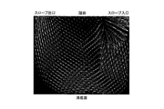
第3実施形態では、第2実施形態に比べ、空気案内突部144、146に代えて、溝深さが深くなるに従い、トレッド面視で空気受入溝122の溝長手方向外側に位置するようにタイヤ径方向K1に対してそれぞれ傾斜している空気案内突部154、156が配置されている。空気案内突部154、156は、何れも、溝壁面側から見て直線状となっている。
In the third embodiment, in place of the air guide protrusions 144 and 146, as compared with the second embodiment, as the groove depth increases, the air receiving groove 122 is positioned on the outer side in the longitudinal direction of the groove in the tread surface view. Air guide protrusions 154 and 156 that are inclined with respect to the tire radial direction K1 are disposed. Each of the air guide protrusions 154 and 156 is linear when viewed from the groove wall surface side.
第2実施形態により、空気案内突部154、156よりもトレッド面視で溝長手方向外側の溝内へ流入した空気は、溝底に行くほど第2実施形態に比べてガイド流路が狭まるので、溝底に向かう空気の流速を増大させることができる。従って、第2実施形態よりも更に放熱性を高める(例えば、第2実施形態に比べて放熱性を一割弱程度高める)ことが可能になる。
According to the second embodiment, the air that has flowed into the groove on the outer side in the longitudinal direction of the groove in the tread surface view from the air guide protrusions 154 and 156 becomes narrower as compared with the second embodiment toward the groove bottom. The flow rate of air toward the groove bottom can be increased. Therefore, it is possible to further improve the heat dissipation performance than the second embodiment (for example, increase the heat dissipation performance by about a little less than 10% compared to the second embodiment).
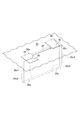
(第4実施形態)
次に、第4実施形態を説明する。図14には、第4実施形態のタイヤの踏面の部分斜視図が示されている。 (Fourth embodiment)
Next, a fourth embodiment will be described. FIG. 14 is a partial perspective view of the tread surface of the tire according to the fourth embodiment.
次に、第4実施形態を説明する。図14には、第4実施形態のタイヤの踏面の部分斜視図が示されている。 (Fourth embodiment)
Next, a fourth embodiment will be described. FIG. 14 is a partial perspective view of the tread surface of the tire according to the fourth embodiment.
第4実施形態では、第2実施形態に比べ、空気案内突部144、146に代えて、溝深さが深くなるに従い、トレッド面視で空気受入溝122の溝長手方向外側に位置するようにタイヤ径方向K1に対してそれぞれ傾斜している空気案内突部164、166が配置されている。
In the fourth embodiment, in place of the air guide protrusions 144 and 146, as compared with the second embodiment, as the groove depth increases, the air receiving groove 122 is positioned on the outer side in the longitudinal direction of the groove in the tread surface view. Air guide protrusions 164 and 166 that are inclined with respect to the tire radial direction K1 are disposed.
第4実施形態では、空気案内突部164、166は、第3実施形態に比べ、溝壁面側から見て湾曲しており、これにより、空気案内突部164、166のタイヤ径方向内側端部(溝底側の端部)にまで空気がスムーズに流れ易くなっている。
In the fourth embodiment, the air guide protrusions 164 and 166 are curved as viewed from the groove wall surface side as compared with the third embodiment, and thereby, the end portions in the tire radial direction of the air guide protrusions 164 and 166 are formed. It is easy for air to smoothly flow to (the end on the groove bottom side).
(第5実施形態)
次に、第5実施形態を説明する。図15には、第5実施形態のタイヤの踏面の部分斜視図が示されている。 (Fifth embodiment)
Next, a fifth embodiment will be described. FIG. 15 is a partial perspective view of the tread surface of the tire according to the fifth embodiment.
次に、第5実施形態を説明する。図15には、第5実施形態のタイヤの踏面の部分斜視図が示されている。 (Fifth embodiment)
Next, a fifth embodiment will be described. FIG. 15 is a partial perspective view of the tread surface of the tire according to the fifth embodiment.
第5実施形態では、第4実施形態に比べ、空気案内突部164、166に代えて空気案内突部174、176が配置されている。空気案内突部174では、タイヤ径方向内側端部(溝底側の端部)に、空気をトレッド面視で溝長手方向内側に案内するタイヤ径方向内側部分174gを有する。同様に、空気案内突部176も、タイヤ径方向内側端部(溝底側の端部)に、空気をトレッド面視で溝長手方向内側に案内するタイヤ径方向内側部分176gを有する。
In the fifth embodiment, air guide protrusions 174 and 176 are arranged instead of the air guide protrusions 164 and 166 as compared with the fourth embodiment. The air guide protrusion 174 has a tire radial inner portion 174g that guides air inward in the longitudinal direction of the groove as viewed in the tread surface, at the tire radial inner end (end on the groove bottom side). Similarly, the air guide protrusion 176 also has a tire radial inner portion 176g that guides air inward in the groove longitudinal direction as viewed in the tread surface, at the tire radial inner end (end on the groove bottom side).
これにより、溝底の表面を流動する空気量が大幅に増大するので、第4実施形態に比べ、更に効率的に溝底を冷却することができる。
This significantly increases the amount of air flowing on the surface of the groove bottom, so that the groove bottom can be cooled more efficiently than in the fourth embodiment.
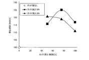
(解析計算例1)
本発明者は、第2実施形態のタイヤ110に関し、突出高さH1を空気受入溝122の50%に設定し、空気受入溝122の溝深さD1に対する空気案内突部144,146の上下方向深さE1の比をパラメータとして変更し(50%、75%、100%)、溝底全体の熱伝達率を解析計算により算出した。ここで溝底全体とは、溝底122cを意味し、その領域平均熱伝達率を算出した(解析計算例2でも同様である)。算出結果を図16に示す。 (Analysis calculation example 1)
The inventor sets the protrusion height H1 to 50% of theair receiving groove 122 in the tire 110 of the second embodiment, and the air guide protrusions 144 and 146 in the vertical direction with respect to the groove depth D1 of the air receiving groove 122. The ratio of the depth E1 was changed as a parameter (50%, 75%, 100%), and the heat transfer coefficient of the entire groove bottom was calculated by analytical calculation. Here, the entire groove bottom means the groove bottom 122c, and the region average heat transfer coefficient was calculated (the same applies to the analytical calculation example 2). The calculation results are shown in FIG.
本発明者は、第2実施形態のタイヤ110に関し、突出高さH1を空気受入溝122の50%に設定し、空気受入溝122の溝深さD1に対する空気案内突部144,146の上下方向深さE1の比をパラメータとして変更し(50%、75%、100%)、溝底全体の熱伝達率を解析計算により算出した。ここで溝底全体とは、溝底122cを意味し、その領域平均熱伝達率を算出した(解析計算例2でも同様である)。算出結果を図16に示す。 (Analysis calculation example 1)
The inventor sets the protrusion height H1 to 50% of the
また、突出高さH1を空気受入溝122の25%に設定し、空気受入溝深さに対するガイド深さの比をパラメータとして変更(50%、75%、100%)することで、同様に解析計算で熱伝達率算出した。算出結果を図16に併せて示す。
Similarly, the projection height H1 is set to 25% of the air receiving groove 122, and the ratio of the guide depth to the air receiving groove depth is changed as a parameter (50%, 75%, 100%) in the same manner. The heat transfer coefficient was calculated. The calculation results are also shown in FIG.
図13に示すように、突出高さH1を空気受入溝122の50%に設定した場合、空気受入溝122の溝深さD1に対する空気案内突部144、146の上下方向深さE1が75%付近で熱伝達率が最も高くなるという結果になった。
As shown in FIG. 13, when the protrusion height H1 is set to 50% of the air receiving groove 122, the vertical depth E1 of the air guide protrusions 144 and 146 with respect to the groove depth D1 of the air receiving groove 122 is 75%. As a result, the heat transfer coefficient was highest in the vicinity.
また、突出高さH1を空気受入溝122の25%に設定した場合、熱伝達率は、空気受入溝122の溝深さD1に対する空気案内突部144、146の上下方向深さE1が50%で最も高く、空気受入溝122の溝深さD1に対する空気案内突部144、146の上下方向深さE1の比がこれ以上大きくなるほど漸減する、という結果になった。
When the protrusion height H1 is set to 25% of the air receiving groove 122, the heat transfer rate is 50% of the vertical depth E1 of the air guiding protrusions 144 and 146 with respect to the groove depth D1 of the air receiving groove 122. As a result, the ratio of the vertical depth E1 of the air guide protrusions 144 and 146 to the groove depth D1 of the air receiving groove 122 gradually decreases as the ratio increases.
(解析計算例2)
本発明者は、第3実施形態のタイヤに関し、突出高さH1を空気受入溝122の50%に設定し、空気受入溝の溝深さD1に対する空気案内突部154、156の上下方向深さE1の比を75%に設定して、溝底全体の熱伝達率を解析計算により算出した。算出結果を図17に示す。なお、図17では、比較のために、解析計算例1で、第2実施形態のタイヤ110に関し、突出高さH1を空気受入溝122の50%に設定し、空気受入溝122の溝深さD1に対する空気案内突部154、156の上下方向深さE1の比を75%に設定したときの熱伝達率の解析計算結果も併せて図示している。 (Analysis calculation example 2)
The inventor sets the protrusion height H1 to 50% of theair receiving groove 122 in the tire of the third embodiment, and the vertical depths of the air guide protrusions 154 and 156 with respect to the groove depth D1 of the air receiving groove. The ratio of E1 was set to 75%, and the heat transfer coefficient of the entire groove bottom was calculated by analytical calculation. The calculation results are shown in FIG. In FIG. 17, for comparison, in analysis calculation example 1, with respect to the tire 110 of the second embodiment, the protrusion height H1 is set to 50% of the air receiving groove 122 and the groove depth of the air receiving groove 122 is set. The analysis calculation result of the heat transfer coefficient when the ratio of the vertical direction depth E1 of the air guide protrusions 154 and 156 to D1 is set to 75% is also illustrated.
本発明者は、第3実施形態のタイヤに関し、突出高さH1を空気受入溝122の50%に設定し、空気受入溝の溝深さD1に対する空気案内突部154、156の上下方向深さE1の比を75%に設定して、溝底全体の熱伝達率を解析計算により算出した。算出結果を図17に示す。なお、図17では、比較のために、解析計算例1で、第2実施形態のタイヤ110に関し、突出高さH1を空気受入溝122の50%に設定し、空気受入溝122の溝深さD1に対する空気案内突部154、156の上下方向深さE1の比を75%に設定したときの熱伝達率の解析計算結果も併せて図示している。 (Analysis calculation example 2)
The inventor sets the protrusion height H1 to 50% of the
図17から判るように、空気受入溝の溝深さD1に対する空気案内突部154、156の上下方向深さE1の比を75%とした場合、第2実施形態よりも第3実施形態のほうが熱伝達率が高いという結果になった。
As can be seen from FIG. 17, when the ratio of the vertical depth E1 of the air guide protrusions 154 and 156 to the groove depth D1 of the air receiving groove is 75%, the third embodiment is more than the second embodiment. The result was a high heat transfer rate.
(解析計算例3)
本発明者は、第2実施形態のタイヤの一例で、空気受入溝122の溝壁面における空気流動を解析計算により求めた。溝壁面での空気流動に関して本解析計算で得られた模式図を図18に示す。 (Analysis calculation example 3)
The present inventor obtained the air flow on the groove wall surface of theair receiving groove 122 by an analytical calculation in an example of the tire of the second embodiment. FIG. 18 shows a schematic diagram obtained by this analysis calculation regarding the air flow on the groove wall surface.
本発明者は、第2実施形態のタイヤの一例で、空気受入溝122の溝壁面における空気流動を解析計算により求めた。溝壁面での空気流動に関して本解析計算で得られた模式図を図18に示す。 (Analysis calculation example 3)
The present inventor obtained the air flow on the groove wall surface of the
また、従来のタイヤの一例として、第2実施形態のタイヤで空気案内突部144を形成しない例について、同様に、空気受入溝およびその両端側にそれぞれ連通する空気受入溝122における空気流動を解析計算により求めた。得られた模式図を図19に示す。
In addition, as an example of a conventional tire, in the example in which the air guide protrusion 144 is not formed in the tire of the second embodiment, similarly, the air flow in the air receiving groove and the air receiving groove 122 communicating with both ends thereof is analyzed. Obtained by calculation. The obtained schematic diagram is shown in FIG.
図18、図19から判るように、空気案内突部144、146を配置したタイヤ(図18、第2実施形態の一例)のほうが配置しないタイヤ(図19、従来例の一例)に比べ、溝底で空気の流動が良好であるという結果になった。
As can be seen from FIGS. 18 and 19, the tire (FIG. 18, an example of the second embodiment) in which the air guiding protrusions 144 and 146 are arranged is more grooved than the tire (FIG. 19, an example of the conventional example) that is not arranged. The result was good air flow at the bottom.
(他の実施形態)
以上、本開示による複数の実施形態について説明したが、本開示は、上記実施形態に限定して解釈されるものではなく、本開示の要旨を逸脱しない範囲内において種々の実施形態及び組み合わせに適用することができる。また、上記実施形態は、この発明の技術的思想を具体化するための例示であり、各実施形態の説明において明示している構成の組み合わせばかりではなく、特に組み合わせに支障が生じなければ、明示していなくても複数の実施形態の構成同士を部分的に組み合せることができる。例えば第1実施形態に第2~5実施形態の空気案内突部を適用してもよい。 (Other embodiments)
Although a plurality of embodiments according to the present disclosure have been described above, the present disclosure is not construed as being limited to the above embodiments, and can be applied to various embodiments and combinations without departing from the gist of the present disclosure. can do. Further, the above embodiment is an example for embodying the technical idea of the present invention, and is not limited to the combination of the configurations specified in the description of each embodiment. Even if it does not do, the structure of several embodiment can be combined partially. For example, the air guide protrusions of the second to fifth embodiments may be applied to the first embodiment.
また、上記第3~5実施形態において、空気案内突部は、溝深さが深くなるに従い、トレッド面視で空気受入溝122の溝長手方向外側に位置するようにタイヤ径方向K1に対してそれぞれ傾斜して配置されている。上記第3~5実施形態と第1実施形態と組み合わせる場合、空気案内溝26、30の空気受入溝22の長手方向Xの溝幅が、溝深さが深くなるに従って狭まるものであってもよい。
Further, in the third to fifth embodiments, the air guide protrusion is positioned with respect to the tire radial direction K1 so as to be positioned on the outer side in the groove longitudinal direction of the air receiving groove 122 in the tread surface view as the groove depth increases. Each is inclined. When the third to fifth embodiments are combined with the first embodiment, the groove width in the longitudinal direction X of the air receiving groove 22 of the air guide grooves 26, 30 may be narrowed as the groove depth increases. .
本出願は、2015年3月19日に出願された日本国特許願第2015-055752号および2015年7月10日に出願された日本国特許願第2015-138538号に基づく優先権を主張しており、この出願の全内容が参照により本明細書に組み込まれる。
This application claims priority based on Japanese Patent Application No. 2015-055552 filed on March 19, 2015 and Japanese Patent Application No. 2015-138538 filed on July 10, 2015. The entire contents of this application are hereby incorporated by reference.
本発明によれば、トレッド部の深部又はその近傍に空気を効率良く流動させることで、トレッド部の深部を十分に冷却することができるタイヤを提供することができる。
According to the present invention, it is possible to provide a tire that can sufficiently cool the deep portion of the tread portion by efficiently flowing air in the deep portion of the tread portion or in the vicinity thereof.
10、110 タイヤ 12、112 トレッド部 20 中央陸部(踏面) 22、122 空気受入溝 22a、22b、122a、122b 空気受入溝の溝壁面 22c、122c 空気受入溝の溝底 122m 空気受入溝本体部 122p、112q 空気受入溝サイド部 24、124 空気導入溝 24a、24b、124a、124b 空気導入溝の溝壁面 24c、124c 空気導入溝の溝底(底面) 124cb タイヤ径方向内側端 26 空気案内溝(空気案内部) 26a 空気案内溝の溝壁面 26b 空気案内溝の溝壁面(空気案内壁) 26c 空気案内溝の溝底 26d、26e 空気案内溝の一端及び他端 28、128 他の空気導入溝 28a、28b、128a、128b 他の空気導入溝の溝壁面 28c、128c 他の空気導入溝の溝底(底面) 30 他の空気案内溝 30a 他の空気案内溝の溝壁面 30b 他の空気案内溝の溝壁面(空気案内壁) 30c 他の空気案内溝の溝底 30d、30e 他の空気案内溝の一端及び他端 144、146、154、156、164、166、174、176 空気案内突部(空気案内部) 144b、146b タイヤ径方向内側端 144h、146h タイヤ径方向外側端 144f、146f 側壁 D、D1 溝深さ W、W1 溝幅 H1 突出高さ
10, 110 tires 12, 112 tread part 20, central land part (tread) 22, 122 air receiving groove 22a, 22b, 122a, 122b air receiving groove groove wall surface 22c, 122c air receiving groove groove bottom 122m air receiving groove main body part 122p, 112q Air receiving groove side portion 24, 124 Air introducing groove 24a, 24b, 124a, 124b Air introducing groove groove wall surface 24c, 124c Air introducing groove groove bottom (bottom surface) 124cb Tire radial inner end 26 Air guiding groove ( Air guide part) 26a Air guide groove wall surface 26b Air guide groove wall surface (air guide wall) 26c Air guide groove groove bottom 26d, 26e Air guide groove one end and other end 28, 128 Other air introduction groove 28a , 28b, 128a, 128b Other air introduction Groove surface 28c, 128c groove bottom (bottom surface) of other air introduction groove 30 other air guide groove 30a groove surface of other air guide groove 30b groove surface of other air guide groove (air guide wall) 30c other air Guide groove groove bottom 30d, 30e One end and the other end of other air guide grooves 144, 146, 154, 156, 164, 166, 174, 176 Air guide protrusions (air guide portions) 144b, 146b Tire radial inner end 144h, 146h, tire radial direction outer end 144f, 146f side wall D, D1, groove depth W, W1, groove width H1, protrusion height
Claims (15)
- タイヤトレッド部に設けられ、タイヤ周方向と交差する方向へ伸び、かつ溝深さより小さい溝幅を有する少なくとも1つの空気受入溝と、
トレッド面側に開口するとともに前記空気受入溝に連通し、タイヤ回転に伴ってトレッド面側の空気を前記空気受入溝へ導入する空気導入溝と、
前記空気受入溝に交差し、かつ前記空気受入溝に交差する位置において前記空気受入溝の溝長手方向中央位置に対して外向きである空気案内面を有し、前記空気導入溝によって前記空気受入溝へ導入された空気を前記空気案内面によって前記空気受入溝の溝底側へ案内する空気案内部と、を備えるタイヤ。 At least one air receiving groove provided in the tire tread portion, extending in a direction crossing the tire circumferential direction and having a groove width smaller than the groove depth;
An air introduction groove that opens on the tread surface side and communicates with the air receiving groove, and introduces air on the tread surface side into the air receiving groove as the tire rotates;
An air guide surface that intersects the air receiving groove and is outward from a central position in the longitudinal direction of the air receiving groove at a position that intersects the air receiving groove, and the air receiving groove is used to receive the air. A tire comprising: an air guide portion that guides air introduced into the groove to the groove bottom side of the air receiving groove by the air guide surface. - 前記空気導入溝は、前記空気受入溝に向かうに連れて溝深さが深くなる請求項1に記載のタイヤ。 The tire according to claim 1, wherein the air introduction groove has a groove depth that becomes deeper toward the air receiving groove.
- 前記空気導入溝は、前記空気受入溝のタイヤ周方向に相対する溝壁面の一方側の溝壁面に連通しており、
前記空気案内部は、
前記空気受入溝と連通し、
前記空気受入溝のタイヤ周方向に相対する溝壁面の他方側の溝壁面に連通し、
タイヤ径方向外側端が、前記空気導入溝と前記空気受入溝が交差する径方向位置よりもタイヤ径方向外側にあり、
タイヤ径方向内側端が、前記空気受入溝の溝深さの半分の位置よりもタイヤ径方向内側にあり、
前記空気導入溝と少なくともタイヤ周方向において部分的に対向している空気案内溝を有する請求項1または2に記載のタイヤ。 The air introduction groove communicates with the groove wall surface on one side of the groove wall surface facing the tire circumferential direction of the air receiving groove,
The air guide part
Communicating with the air receiving groove,
Communicating with the groove wall surface on the other side of the groove wall surface facing the tire circumferential direction of the air receiving groove,
The tire radial direction outer end is on the tire radial direction outer side than the radial position where the air introduction groove and the air receiving groove intersect,
The tire radial direction inner end is located on the tire radial direction inner side than the half position of the groove depth of the air receiving groove,
The tire according to claim 1, further comprising an air guide groove that is partially opposed to the air introduction groove at least in the tire circumferential direction. - 前記空気案内溝は、前記空気受入溝と同じ溝深さを有し、
前記空気案内溝の溝壁は、前記空気受入溝の側壁面と少なくとも一部が径方向において平行である請求項3に記載のタイヤ。 The air guide groove has the same groove depth as the air receiving groove,
The tire according to claim 3, wherein the groove wall of the air guide groove is at least partially parallel to the side wall surface of the air receiving groove in the radial direction. - 前記空気案内溝の一端及び他端は、それぞれ踏面と前記空気受入溝の溝底との間に位置し、前記空気受入溝の溝壁に対して凹む凹部からなる請求項3に記載のタイヤ。 4. The tire according to claim 3, wherein one end and the other end of the air guide groove are each formed between a tread surface and a groove bottom of the air receiving groove and are recessed with respect to a groove wall of the air receiving groove.
- 前記空気受入溝に連通するもう一組の他の空気導入溝及び他の空気案内溝を有し、
前記他の空気導入溝は、前記空気受入溝の周方向に相対する溝壁面のうち他方側の溝壁面に連通し、
前記空気案内溝は、前記空気受入溝の周方向に相対する溝壁面のうち周方向一方側の溝壁面に連通している請求項3~5のいずれか1項に記載のタイヤ。 Another air introduction groove and another air guide groove communicating with the air receiving groove,
The other air introduction groove communicates with the groove wall surface on the other side among the groove wall surfaces facing the circumferential direction of the air receiving groove,
The tire according to any one of claims 3 to 5, wherein the air guide groove communicates with a groove wall surface on one side in a circumferential direction among groove wall surfaces opposed to the circumferential direction of the air receiving groove. - 前記一組の空気導入溝及び空気案内溝と、前記もう一組の他の空気導入溝及び他の空気案内溝とは、それぞれ前記空気受入溝の長手方向に互いに間隔をおいて配置されている請求項6に記載のタイヤ。 The one set of air introduction grooves and air guide grooves and the another set of other air introduction grooves and other air guide grooves are arranged at intervals from each other in the longitudinal direction of the air receiving groove. The tire according to claim 6.
- 前記空気受入溝に連通するもう一組の他の空気導入溝及び他の空気案内溝を有し、前記他の空気導入溝は前記空気受入溝の他方の溝壁面と交差し、また、前記他方の案内溝は前記空気受入溝の一方の溝壁面に開放しており、
前記空気案内溝の一端が踏面に開放しており、
前記タイヤの踏面上における前記空気導入溝及び他の空気導入溝の正投影面積の和(A)に対する前記空気案内溝及び他の空気案内溝の正投影面積の和(B)の比である開口率(B/A)は、50%以下である、請求項3または4に記載のタイヤ。 Another air introduction groove and another air guide groove communicating with the air receiving groove, the other air introduction groove intersecting the other groove wall surface of the air receiving groove, and the other The guide groove is open on one groove wall surface of the air receiving groove,
One end of the air guide groove is open to the tread,
An opening that is a ratio of the sum (B) of the orthographic projection areas of the air guide groove and other air guide grooves to the sum (A) of the orthographic projection areas of the air introduction groove and other air introduction grooves on the tire tread. The tire according to claim 3 or 4, wherein the rate (B / A) is 50% or less. - 前記一組の空気導入溝及び空気案内溝と、前記もう一組の他の空気導入溝及び他の空気案内溝とは、それぞれ前記空気受入溝の長手方向に互いに間隔をおいて配置されている請求項8に記載のタイヤ。 The one set of air introduction grooves and air guide grooves and the another set of other air introduction grooves and other air guide grooves are arranged at intervals from each other in the longitudinal direction of the air receiving groove. The tire according to claim 8.
- 前記空気案内部は、
前記空気受入溝の溝壁に配置されて前記空気受入溝の溝幅方向へ突出し、溝底に向かってタイヤ径方向に延びている空気案内突部を有し、
前記空気案内突部は、タイヤ回転に伴って前記空気導入溝によって前記空気受入溝へ案内された空気を前記空気受入溝の溝底側へ案内する請求項1~9のいずれか1項に記載のタイヤ。 The air guide part
An air guide protrusion that is disposed on the groove wall of the air receiving groove and protrudes in the groove width direction of the air receiving groove and extends in the tire radial direction toward the groove bottom;
10. The air guide protrusion according to claim 1, wherein the air guide protrusion guides air guided to the air receiving groove by the air introduction groove as the tire rotates toward a groove bottom side of the air receiving groove. Tires. - 前記空気導入溝および前記空気案内突部は、トレッド面視で前記空気受入溝の溝長手方向中央位置に対して溝長手方向両側にそれぞれ配置され、
前記空気受入溝は、トレッド面視で、前記空気案内突部から溝長手方向中央部側に位置する空気受入溝本体部と、前記空気案内突部から溝長手方向外側に位置して前記空気導入溝が連通する空気受入溝サイド部とで構成されている、請求項10に記載のタイヤ。 The air introduction groove and the air guide protrusion are respectively disposed on both sides of the groove longitudinal direction with respect to the groove longitudinal center position of the air receiving groove in a tread surface view,
The air receiving groove is, when viewed from the tread surface, the air receiving groove main body portion positioned on the center side in the groove longitudinal direction from the air guiding protrusion, and the air introduction groove positioned on the outer side in the groove longitudinal direction from the air guiding protrusion. The tire according to claim 10, wherein the tire is configured with an air receiving groove side portion that communicates with the groove. - 前記空気案内突部のタイヤ径方向内側端は、前記空気受入溝の溝底に到達していないことを特徴とする請求項10または11に記載のタイヤ。 The tire according to claim 10 or 11, wherein an inner end in the tire radial direction of the air guide protrusion does not reach a groove bottom of the air receiving groove.
- 前記空気案内突部の前記溝幅方向への突出高さは、タイヤ径方向内側に行くに従い徐々に低くなっている請求項10~12のいずれか1項に記載のタイヤ。 The tire according to any one of claims 10 to 12, wherein a protrusion height of the air guide protrusion in the groove width direction is gradually lowered toward the inner side in the tire radial direction.
- 前記空気案内突部は、タイヤ径方向内側に行くに従い前記空気受入溝のトレッド面視長手方向外側へ傾斜している、請求項10~13のいずれか1項に記載のタイヤ。 The tire according to any one of claims 10 to 13, wherein the air guide protrusion is inclined outward in the longitudinal direction of the air receiving groove as viewed in the tread surface as it goes inward in the tire radial direction.
- 前記空気導入溝、および、前記空気案内突部が、前記空気受入溝のトレッド面視長手方向両側に、トレッド面視で点対称となるように配置されている、請求項10~14のいずれか1項に記載のタイヤ。 The air introduction groove and the air guide protrusion are arranged on both sides of the air receiving groove in the longitudinal direction of the tread surface so as to be symmetric with respect to the tread surface. The tire according to item 1.
Priority Applications (4)
| Application Number | Priority Date | Filing Date | Title |
|---|---|---|---|
| US15/558,426 US20180056730A1 (en) | 2015-03-19 | 2016-03-16 | Tire |
| ES16765007T ES2770337T3 (en) | 2015-03-19 | 2016-03-16 | Tire |
| EP16765007.6A EP3272552B1 (en) | 2015-03-19 | 2016-03-16 | Tire |
| CN201680016602.3A CN107428203B (en) | 2015-03-19 | 2016-03-16 | Tire |
Applications Claiming Priority (4)
| Application Number | Priority Date | Filing Date | Title |
|---|---|---|---|
| JP2015-055752 | 2015-03-19 | ||
| JP2015055752A JP6578114B2 (en) | 2015-03-19 | 2015-03-19 | tire |
| JP2015-138538 | 2015-07-10 | ||
| JP2015138538 | 2015-07-10 |
Publications (1)
| Publication Number | Publication Date |
|---|---|
| WO2016148178A1 true WO2016148178A1 (en) | 2016-09-22 |
Family
ID=56919887
Family Applications (1)
| Application Number | Title | Priority Date | Filing Date |
|---|---|---|---|
| PCT/JP2016/058285 WO2016148178A1 (en) | 2015-03-19 | 2016-03-16 | Tire |
Country Status (5)
| Country | Link |
|---|---|
| US (1) | US20180056730A1 (en) |
| EP (1) | EP3272552B1 (en) |
| CN (1) | CN107428203B (en) |
| ES (1) | ES2770337T3 (en) |
| WO (1) | WO2016148178A1 (en) |
Families Citing this family (2)
| Publication number | Priority date | Publication date | Assignee | Title |
|---|---|---|---|---|
| JP6890086B2 (en) | 2017-12-12 | 2021-06-18 | 株式会社ブリヂストン | Heavy load tires |
| JP7215900B2 (en) * | 2018-12-27 | 2023-01-31 | Toyo Tire株式会社 | pneumatic tire |
Citations (7)
| Publication number | Priority date | Publication date | Assignee | Title |
|---|---|---|---|---|
| JP2007191093A (en) * | 2006-01-20 | 2007-08-02 | Bridgestone Corp | Tire for construction vehicle |
| JP2007230399A (en) * | 2006-03-01 | 2007-09-13 | Bridgestone Corp | Pneumatic tire |
| WO2008029563A1 (en) * | 2006-09-05 | 2008-03-13 | Bridgestone Corporation | Tire for construction vehicle |
| JP2009179219A (en) * | 2008-01-31 | 2009-08-13 | Bridgestone Corp | Pneumatic tire |
| JP2012179948A (en) * | 2011-02-28 | 2012-09-20 | Bridgestone Corp | Radial tire for construction vehicle |
| JP2014084109A (en) * | 2012-10-26 | 2014-05-12 | The Goodyear Tire & Rubber Co | Off-road tire |
| WO2014142346A1 (en) * | 2013-03-13 | 2014-09-18 | 株式会社ブリヂストン | Pneumatic tire |
Family Cites Families (7)
| Publication number | Priority date | Publication date | Assignee | Title |
|---|---|---|---|---|
| JPH02241806A (en) * | 1989-03-15 | 1990-09-26 | Bridgestone Corp | Pneumatic tire having sipes with gap difference and sipe forming blade of tire mold |
| DE19651792A1 (en) * | 1996-12-12 | 1998-06-18 | Continental Ag | Vehicle tires with a tread with notches |
| EP1580032B1 (en) * | 2004-03-26 | 2010-10-20 | Continental Reifen Deutschland GmbH | Pneumatic tyre |
| JP5099914B2 (en) * | 2008-10-03 | 2012-12-19 | 東洋ゴム工業株式会社 | Pneumatic tire |
| DE102009044246A1 (en) * | 2009-10-14 | 2011-05-12 | Continental Reifen Deutschland Gmbh | Tread pattern of a pneumatic vehicle tire |
| JP5429267B2 (en) * | 2011-11-28 | 2014-02-26 | 横浜ゴム株式会社 | Pneumatic tire |
| JP5977696B2 (en) * | 2013-03-13 | 2016-08-24 | 株式会社ブリヂストン | Pneumatic tire |
-
2016
- 2016-03-16 EP EP16765007.6A patent/EP3272552B1/en active Active
- 2016-03-16 US US15/558,426 patent/US20180056730A1/en not_active Abandoned
- 2016-03-16 ES ES16765007T patent/ES2770337T3/en active Active
- 2016-03-16 WO PCT/JP2016/058285 patent/WO2016148178A1/en active Application Filing
- 2016-03-16 CN CN201680016602.3A patent/CN107428203B/en active Active
Patent Citations (7)
| Publication number | Priority date | Publication date | Assignee | Title |
|---|---|---|---|---|
| JP2007191093A (en) * | 2006-01-20 | 2007-08-02 | Bridgestone Corp | Tire for construction vehicle |
| JP2007230399A (en) * | 2006-03-01 | 2007-09-13 | Bridgestone Corp | Pneumatic tire |
| WO2008029563A1 (en) * | 2006-09-05 | 2008-03-13 | Bridgestone Corporation | Tire for construction vehicle |
| JP2009179219A (en) * | 2008-01-31 | 2009-08-13 | Bridgestone Corp | Pneumatic tire |
| JP2012179948A (en) * | 2011-02-28 | 2012-09-20 | Bridgestone Corp | Radial tire for construction vehicle |
| JP2014084109A (en) * | 2012-10-26 | 2014-05-12 | The Goodyear Tire & Rubber Co | Off-road tire |
| WO2014142346A1 (en) * | 2013-03-13 | 2014-09-18 | 株式会社ブリヂストン | Pneumatic tire |
Also Published As
| Publication number | Publication date |
|---|---|
| EP3272552B1 (en) | 2019-11-13 |
| EP3272552A1 (en) | 2018-01-24 |
| ES2770337T3 (en) | 2020-07-01 |
| EP3272552A4 (en) | 2018-03-21 |
| US20180056730A1 (en) | 2018-03-01 |
| CN107428203B (en) | 2019-08-27 |
| CN107428203A (en) | 2017-12-01 |
Similar Documents
| Publication | Publication Date | Title |
|---|---|---|
| JP6149032B2 (en) | Tire tread with grooves with internal space | |
| JP6514869B2 (en) | Pneumatic tire | |
| JP5805123B2 (en) | Pneumatic tire | |
| JP2014522772A5 (en) | ||
| JP2006188221A (en) | Tire tread comprising tread block with undercut structure | |
| JP5913238B2 (en) | Pneumatic tire | |
| WO2016148178A1 (en) | Tire | |
| CN112334331B (en) | Heavy load tire | |
| JP6578114B2 (en) | tire | |
| JP5697868B2 (en) | Transport vehicle tires | |
| JP2019098998A (en) | tire | |
| JP4583846B2 (en) | Pneumatic tire | |
| JP4420598B2 (en) | Pneumatic tire | |
| JP2016020169A (en) | tire | |
| JP6735131B2 (en) | tire | |
| JP5557943B1 (en) | Pneumatic tire | |
| JP6161947B2 (en) | tire | |
| JP6161946B2 (en) | tire | |
| JP2013006574A (en) | Pneumatic tire | |
| CN112339506B (en) | Pneumatic tire | |
| JP6534300B2 (en) | tire | |
| JP2014000892A (en) | Tire | |
| JP2014000891A (en) | Tire | |
| JP2009001171A (en) | Pneumatic tire for automated guideway transit vehicle | |
| JP2019104362A (en) | Tire for heavy load |
Legal Events
| Date | Code | Title | Description |
|---|---|---|---|
| 121 | Ep: the epo has been informed by wipo that ep was designated in this application |
Ref document number: 16765007 Country of ref document: EP Kind code of ref document: A1 |
|
| WWE | Wipo information: entry into national phase |
Ref document number: 15558426 Country of ref document: US |
|
| NENP | Non-entry into the national phase |
Ref country code: DE |
|
| REEP | Request for entry into the european phase |
Ref document number: 2016765007 Country of ref document: EP |