WO2016147960A1 - Polarizing plate and circularly polarizing plate - Google Patents
Polarizing plate and circularly polarizing plate Download PDFInfo
- Publication number
- WO2016147960A1 WO2016147960A1 PCT/JP2016/057221 JP2016057221W WO2016147960A1 WO 2016147960 A1 WO2016147960 A1 WO 2016147960A1 JP 2016057221 W JP2016057221 W JP 2016057221W WO 2016147960 A1 WO2016147960 A1 WO 2016147960A1
- Authority
- WO
- WIPO (PCT)
- Prior art keywords
- liquid crystal
- polarizer
- group
- polarizing plate
- formula
- Prior art date
Links
- 0 CCN(CC)c(cc1)ccc1N=Nc(cc1)ccc1N=Nc(cc1)ccc1N=Nc1ccc(*)cc1 Chemical compound CCN(CC)c(cc1)ccc1N=Nc(cc1)ccc1N=Nc(cc1)ccc1N=Nc1ccc(*)cc1 0.000 description 4
- OOLYJQYHQFVPTM-ZQZMJUSDSA-N CCN(CC)c(cc1)ccc1/N=N/c1nc([s]c(/N=N\c(cc2)ccc2C(C)=O)c2)c2[s]1 Chemical compound CCN(CC)c(cc1)ccc1/N=N/c1nc([s]c(/N=N\c(cc2)ccc2C(C)=O)c2)c2[s]1 OOLYJQYHQFVPTM-ZQZMJUSDSA-N 0.000 description 1
Images


Classifications
-
- G—PHYSICS
- G02—OPTICS
- G02B—OPTICAL ELEMENTS, SYSTEMS OR APPARATUS
- G02B5/00—Optical elements other than lenses
- G02B5/30—Polarising elements
-
- G—PHYSICS
- G02—OPTICS
- G02F—OPTICAL DEVICES OR ARRANGEMENTS FOR THE CONTROL OF LIGHT BY MODIFICATION OF THE OPTICAL PROPERTIES OF THE MEDIA OF THE ELEMENTS INVOLVED THEREIN; NON-LINEAR OPTICS; FREQUENCY-CHANGING OF LIGHT; OPTICAL LOGIC ELEMENTS; OPTICAL ANALOGUE/DIGITAL CONVERTERS
- G02F1/00—Devices or arrangements for the control of the intensity, colour, phase, polarisation or direction of light arriving from an independent light source, e.g. switching, gating or modulating; Non-linear optics
- G02F1/01—Devices or arrangements for the control of the intensity, colour, phase, polarisation or direction of light arriving from an independent light source, e.g. switching, gating or modulating; Non-linear optics for the control of the intensity, phase, polarisation or colour
- G02F1/13—Devices or arrangements for the control of the intensity, colour, phase, polarisation or direction of light arriving from an independent light source, e.g. switching, gating or modulating; Non-linear optics for the control of the intensity, phase, polarisation or colour based on liquid crystals, e.g. single liquid crystal display cells
- G02F1/133—Constructional arrangements; Operation of liquid crystal cells; Circuit arrangements
- G02F1/1333—Constructional arrangements; Manufacturing methods
- G02F1/1335—Structural association of cells with optical devices, e.g. polarisers or reflectors
-
- C—CHEMISTRY; METALLURGY
- C09—DYES; PAINTS; POLISHES; NATURAL RESINS; ADHESIVES; COMPOSITIONS NOT OTHERWISE PROVIDED FOR; APPLICATIONS OF MATERIALS NOT OTHERWISE PROVIDED FOR
- C09K—MATERIALS FOR MISCELLANEOUS APPLICATIONS, NOT PROVIDED FOR ELSEWHERE
- C09K19/00—Liquid crystal materials
- C09K19/04—Liquid crystal materials characterised by the chemical structure of the liquid crystal components, e.g. by a specific unit
- C09K19/42—Mixtures of liquid crystal compounds covered by two or more of the preceding groups C09K19/06 - C09K19/40
-
- C—CHEMISTRY; METALLURGY
- C09—DYES; PAINTS; POLISHES; NATURAL RESINS; ADHESIVES; COMPOSITIONS NOT OTHERWISE PROVIDED FOR; APPLICATIONS OF MATERIALS NOT OTHERWISE PROVIDED FOR
- C09K—MATERIALS FOR MISCELLANEOUS APPLICATIONS, NOT PROVIDED FOR ELSEWHERE
- C09K19/00—Liquid crystal materials
- C09K19/52—Liquid crystal materials characterised by components which are not liquid crystals, e.g. additives with special physical aspect: solvents, solid particles
- C09K19/54—Additives having no specific mesophase characterised by their chemical composition
-
- G—PHYSICS
- G02—OPTICS
- G02B—OPTICAL ELEMENTS, SYSTEMS OR APPARATUS
- G02B5/00—Optical elements other than lenses
- G02B5/30—Polarising elements
- G02B5/3025—Polarisers, i.e. arrangements capable of producing a definite output polarisation state from an unpolarised input state
- G02B5/3033—Polarisers, i.e. arrangements capable of producing a definite output polarisation state from an unpolarised input state in the form of a thin sheet or foil, e.g. Polaroid
- G02B5/3041—Polarisers, i.e. arrangements capable of producing a definite output polarisation state from an unpolarised input state in the form of a thin sheet or foil, e.g. Polaroid comprising multiple thin layers, e.g. multilayer stacks
- G02B5/305—Polarisers, i.e. arrangements capable of producing a definite output polarisation state from an unpolarised input state in the form of a thin sheet or foil, e.g. Polaroid comprising multiple thin layers, e.g. multilayer stacks including organic materials, e.g. polymeric layers
-
- G—PHYSICS
- G02—OPTICS
- G02F—OPTICAL DEVICES OR ARRANGEMENTS FOR THE CONTROL OF LIGHT BY MODIFICATION OF THE OPTICAL PROPERTIES OF THE MEDIA OF THE ELEMENTS INVOLVED THEREIN; NON-LINEAR OPTICS; FREQUENCY-CHANGING OF LIGHT; OPTICAL LOGIC ELEMENTS; OPTICAL ANALOGUE/DIGITAL CONVERTERS
- G02F1/00—Devices or arrangements for the control of the intensity, colour, phase, polarisation or direction of light arriving from an independent light source, e.g. switching, gating or modulating; Non-linear optics
- G02F1/01—Devices or arrangements for the control of the intensity, colour, phase, polarisation or direction of light arriving from an independent light source, e.g. switching, gating or modulating; Non-linear optics for the control of the intensity, phase, polarisation or colour
- G02F1/13—Devices or arrangements for the control of the intensity, colour, phase, polarisation or direction of light arriving from an independent light source, e.g. switching, gating or modulating; Non-linear optics for the control of the intensity, phase, polarisation or colour based on liquid crystals, e.g. single liquid crystal display cells
- G02F1/133—Constructional arrangements; Operation of liquid crystal cells; Circuit arrangements
- G02F1/1333—Constructional arrangements; Manufacturing methods
- G02F1/1335—Structural association of cells with optical devices, e.g. polarisers or reflectors
- G02F1/13363—Birefringent elements, e.g. for optical compensation
-
- H—ELECTRICITY
- H05—ELECTRIC TECHNIQUES NOT OTHERWISE PROVIDED FOR
- H05B—ELECTRIC HEATING; ELECTRIC LIGHT SOURCES NOT OTHERWISE PROVIDED FOR; CIRCUIT ARRANGEMENTS FOR ELECTRIC LIGHT SOURCES, IN GENERAL
- H05B33/00—Electroluminescent light sources
- H05B33/02—Details
-
- H—ELECTRICITY
- H10—SEMICONDUCTOR DEVICES; ELECTRIC SOLID-STATE DEVICES NOT OTHERWISE PROVIDED FOR
- H10K—ORGANIC ELECTRIC SOLID-STATE DEVICES
- H10K50/00—Organic light-emitting devices
-
- H—ELECTRICITY
- H10—SEMICONDUCTOR DEVICES; ELECTRIC SOLID-STATE DEVICES NOT OTHERWISE PROVIDED FOR
- H10K—ORGANIC ELECTRIC SOLID-STATE DEVICES
- H10K50/00—Organic light-emitting devices
- H10K50/80—Constructional details
- H10K50/868—Arrangements for polarized light emission
-
- H—ELECTRICITY
- H10—SEMICONDUCTOR DEVICES; ELECTRIC SOLID-STATE DEVICES NOT OTHERWISE PROVIDED FOR
- H10K—ORGANIC ELECTRIC SOLID-STATE DEVICES
- H10K71/00—Manufacture or treatment specially adapted for the organic devices covered by this subclass
-
- C—CHEMISTRY; METALLURGY
- C09—DYES; PAINTS; POLISHES; NATURAL RESINS; ADHESIVES; COMPOSITIONS NOT OTHERWISE PROVIDED FOR; APPLICATIONS OF MATERIALS NOT OTHERWISE PROVIDED FOR
- C09K—MATERIALS FOR MISCELLANEOUS APPLICATIONS, NOT PROVIDED FOR ELSEWHERE
- C09K2323/00—Functional layers of liquid crystal optical display excluding electroactive liquid crystal layer characterised by chemical composition
- C09K2323/03—Viewing layer characterised by chemical composition
- C09K2323/031—Polarizer or dye
-
- G—PHYSICS
- G02—OPTICS
- G02F—OPTICAL DEVICES OR ARRANGEMENTS FOR THE CONTROL OF LIGHT BY MODIFICATION OF THE OPTICAL PROPERTIES OF THE MEDIA OF THE ELEMENTS INVOLVED THEREIN; NON-LINEAR OPTICS; FREQUENCY-CHANGING OF LIGHT; OPTICAL LOGIC ELEMENTS; OPTICAL ANALOGUE/DIGITAL CONVERTERS
- G02F1/00—Devices or arrangements for the control of the intensity, colour, phase, polarisation or direction of light arriving from an independent light source, e.g. switching, gating or modulating; Non-linear optics
- G02F1/01—Devices or arrangements for the control of the intensity, colour, phase, polarisation or direction of light arriving from an independent light source, e.g. switching, gating or modulating; Non-linear optics for the control of the intensity, phase, polarisation or colour
- G02F1/13—Devices or arrangements for the control of the intensity, colour, phase, polarisation or direction of light arriving from an independent light source, e.g. switching, gating or modulating; Non-linear optics for the control of the intensity, phase, polarisation or colour based on liquid crystals, e.g. single liquid crystal display cells
- G02F1/133—Constructional arrangements; Operation of liquid crystal cells; Circuit arrangements
- G02F1/1333—Constructional arrangements; Manufacturing methods
- G02F1/1335—Structural association of cells with optical devices, e.g. polarisers or reflectors
- G02F1/133528—Polarisers
-
- H—ELECTRICITY
- H10—SEMICONDUCTOR DEVICES; ELECTRIC SOLID-STATE DEVICES NOT OTHERWISE PROVIDED FOR
- H10K—ORGANIC ELECTRIC SOLID-STATE DEVICES
- H10K50/00—Organic light-emitting devices
- H10K50/80—Constructional details
- H10K50/86—Arrangements for improving contrast, e.g. preventing reflection of ambient light
Definitions
- the present invention relates to a polarizing plate and a circularly polarizing plate.
- a circularly polarizing plate is used to prevent reflection of external light in a bright place.
- a circularly polarizing plate for example, one including a polarizing plate (iodine-PVA polarizing plate) in which PVA (polyvinyl alcohol) is dyed with iodine is known (see Patent Document 1).
- a polarizing plate having a low absorbance is desired so as not to absorb light emitted from the organic EL element.
- the absorbance can be lowered by lowering the dyeing concentration of iodine.
- the iodine-PVA polarizing plate having such a low concentration has a problem that iodine sublimates and changes in quality depending on the use environment, and a problem that warpage occurs due to relaxation of PVA stretching. There is.
- the iodine-PVA polarizing plate is difficult to be thinned, and there is a limit in applying it to a display device that is required to be thinner.
- an object of the present invention is to provide a polarizing plate and a circularly polarizing plate that have high light absorption selection performance even in a thin film and are excellent in heat resistance.
- a polarizing plate comprising a substrate and a polarizer, the polarizer having a polarizing layer having a thickness of 5 ⁇ m or less in which a dichroic dye is oriented, and the polarizer at 380 to 760 nm
- a polarizing plate having an absorbance (A1) in the absorption axis direction of 0.3 to 1.5 and an absorbance (A2) in the transmission axis direction of 0.001 to 0.15.
- the dichroic dye is an organic dye.
- a polarizing plate and a circularly polarizing plate that have high light absorption selection performance even in a thin film and are excellent in heat resistance.
- the polarizing plate of the present embodiment includes a base material and a polarizer, and the polarizer has a polarizing layer having a thickness of 5 ⁇ m or less in which the dichroic dye is oriented, and the polarizer has a wavelength of 380 to 760 nm.
- the absorbance (A1) in the absorption axis direction is 0.3 or more and 1.5 or less, and the absorbance (A2) in the transmission axis direction is 0.001 or more and 0.15 or less.
- Polarizer The polarizer according to this embodiment has a polarizing layer having a thickness of 5 ⁇ m or less in which the dichroic dye is oriented.
- This polarizing layer can be formed using a composition containing a dichroic dye (hereinafter, sometimes referred to as “polarizer-forming composition”).
- Dichroic dye those having absorption within a wavelength range of 380 to 800 nm can be used, and an organic dye is preferably used.
- examples of the dichroic dye include azo compounds.
- a dichroic dye (1) having an absorption maximum in the wavelength range of 380 to 550 nm can be used.
- the dichroic dye (1) include a compound represented by the following formula (1) (hereinafter sometimes referred to as “compound (1)”). Trans is preferable for the geometric isomerism of the azobenzene moiety of the compound (1).
- Y in formula (1) is a group represented by the following formula (Y1) or formula (Y2), and preferably a group represented by formula (Y1).
- L is an oxygen atom or —NR—
- R is a hydrogen atom or an alkyl group having 1 to 4 carbon atoms.
- the alkyl group include a methyl group, an ethyl group, an n-propyl group, an isopropyl group, an n-butyl group, an isobutyl group, and a t-butyl group.
- L is preferably an oxygen atom or —NH—, and more preferably an oxygen atom.
- R 1 is a group represented by the following formula (R 1 -1), formula (R 1 -2) or formula (R 1 -3), preferably formula (R 1 -2) or formula (R 1 -3). * In the formula represents a bond.
- each ma is independently preferably an integer of 0 to 10, and more preferably an integer of 0 to 5.
- the two ma may be the same or different, but are preferably the same.
- R 2 represents formula (R 2 -1), formula (R 2 -2), formula (R 2 -3), formula (R 2 -4), formula (R 2 -5) or formula (R 2 -6). And a group represented by formula (R 2 -2), formula (R 2 -5) or formula (R 2 -6), preferably represented by formula (R 2 -6) It is more preferable that it is a group represented.
- R 2 is a group represented by formula (R 2 -1), formula (R 2 -2), formula (R 2 -3), formula (R 2 -5) or formula (R 2 -6)
- Mb contained in the group is preferably an integer of 0 to 10, more preferably an integer of 0 to 5.
- Examples of the compound (1) include compounds represented by the following formulas (1-1) to (1-8).
- the compound (1) is represented by the formula (1-1), the formula (1-2), the formula (1-3), the formula (1-5), the formula (1-7), and the formula (1-8).
- the compounds represented by formula (1-1), formula (1-2), formula (1-3) and formula (1-7) are more preferred.
- Compound (1) is produced, for example, from the compound represented by formula (1X) [compound (1X)] and the compound represented by formula (1Y) [compound (1Y)] by the reaction shown in the following scheme. be able to.
- R 1 , R 2 and Y have the same meaning as described above, and Re 1 and Re 2 are groups that react with each other to form a group represented by Y.
- Examples of the combination of Re 1 and Re 2 include a combination of a carboxy group and a hydroxyl group, a combination of a carboxy group and an amino group (the amino group may be substituted with R), a combination of a carbonyl halide group and a hydroxyl group, and a carbonyl halide.
- a combination of a group and an amino group (such an amino group may be substituted with R), a combination of a carbonyloxyalkyl group and a hydroxyl group, a carbonyloxyalkyl group and an amino group (such an amino group may be substituted with R) ).
- R include an alkyl group having 1 to 4 carbon atoms.
- the compound (1X) having R 1 and the compound (1Y) having R 2 will be described, but a compound in which R 1 is protected with an appropriate protecting group, and R 2 is protected with an appropriate protecting group.
- Compound (1) can also be produced by reacting the compounds with each other and then performing an appropriate deprotection reaction.
- reaction conditions for reacting the compound (1X) and the compound (1Y) optimum known conditions can be appropriately selected according to the types of the compound (1X) and the compound (1Y) to be used.
- the reaction conditions when Re 1 is a carboxy group, Re 2 is a hydroxyl group, and Y is —C ( ⁇ O) —O— are, for example, in a solvent in the presence of an esterification condensing agent.
- the conditions to condense are mentioned.
- the solvent include solvents that can dissolve both the compound (1X) and the compound (1Y), such as chloroform.
- esterification condensing agent include diisopropylcarbodiimide (IPC).
- a base such as dimethylaminopyridine (DMAP) is preferably used in combination.
- the reaction temperature is selected according to the kind of the compound (1X) and the compound (1Y), and for example, a range of ⁇ 15 to 70 ° C. is mentioned, and a range of 0 to 40 ° C. is preferable.
- the reaction time is, for example, in the range of 15 minutes to 48 hours.
- the reaction mixture during the reaction is appropriately sampled, and the degree of disappearance of the compound (1X) and the compound (1Y) and the production of the compound (1) by a known analytical means such as liquid chromatography or gas chromatography. It is also possible to determine by checking the degree.
- the compound (1) can be taken out by a known method such as recrystallization, reprecipitation, extraction and various chromatography, or by combining these operations.
- a dichroic dye (2) having an absorption maximum in the wavelength range of 550 to 700 nm can be used.
- the dichroic dye (2) is a dichroic dye (2-1) having an absorption maximum in a wavelength range of 550 to 600 nm and / or a dichroic dye (2-) having an absorption maximum in a wavelength range of 600 to 700 nm. 2) may be included.
- the dichroic dye (2-1) preferably has an absorption maximum in the wavelength range of 570 to 600 nm, and the dichroic dye (2-2) more preferably has an absorption maximum in the wavelength range of 600 to 680 nm.
- dichroic dye (2) examples include a compound represented by the following formula (2) (hereinafter sometimes referred to as “compound (2)”). Trans is preferable for the geometric isomerism of the azobenzene moiety of the compound (2). In the formula (2), n is 1 or 2.
- Ar 1 and Ar 3 are each independently a group represented by formula (AR-1), formula (AR-2), formula (AR-3) or formula (AR-4). * Represents a bond.
- Ar 2 is a group represented by formula (AR2-1), formula (AR2-2), or formula (AR2-3).
- a 1 and A 2 are each independently a group represented by any of formulas (A-1) to (A-9).
- formula (A-2), formula (A-3), formula (A-5) and (A-6) mc is an integer of 0 to 10, and when two mc are present in the same group, The two mcs are the same or different from each other.
- the compound (2) that can be used as the dichroic dye (2-1) is obtained. Determined.
- a compound (2) that can be used as a dichroic dye (2-2) by combining Ar 1 , Ar 2, and Ar 3 so that the compound (2) has absorption in the wavelength range of 600 to 700 nm. ) Is determined.
- Specific examples of the compound (2) include compounds represented by formulas (2-11) to (2-39), respectively.
- examples of the dichroic dye (2-1) include the formula (2-12), the formula (2-13), the formula (2-18), and the formula (2-20). ), Formula (2-21), formula (2-22), formula (2-23), formula (2-24), formula (2-26), formula (2-27), formula (2-28) And the compounds represented by formula (2-29) and formula (2-30), respectively.
- examples of the dichroic dye (2-2) include formula (2-31), formula (2-32), The compounds represented by the formula (2-33), the formula (2-34), the formula (2-35) and the formula (2-36) are applicable.
- the compounds represented by formula (2-11), formula (2-15) and formula (2-16) are not dyes which absorb at a wavelength of 550 to 700 nm, but are used in combination with other dichroic dyes. can do.
- examples of the dichroic dye (2) include the formula (2-15), the formula (2-16), the formula (2-18), the formula (2-20), the formula (2), 2-21), Formula (2-22), Formula (2-23), Formula (2-27), Formula (2-29), Formula (2-31), Formula (2-32), Formula (2) -33), compounds represented by formula (2-34) and formula (2-35), respectively, are preferred.
- the dichroic dye (2) is produced by a known method described in, for example, JP-A Nos. 58-38756 and 63-301850.
- each content of the dichroic dye is expressed as a content with respect to 100 parts by mass of the polymerizable liquid crystal compound described later, and 3 parts by mass or less. Is preferable, 0.1 to 2.5 parts by mass is more preferable, and 1 to 1.5 parts by mass is more preferable. If each content of the dichroic dye is within the above range, the dichroic dye in the composition for forming a polarizer exhibits sufficient solubility in a solvent. When a polarizer is manufactured, a polarizer free from defects is easily obtained.
- the total amount of the dichroic dye contained in the composition for forming a polarizer is represented by a content with respect to 100 parts by mass of the polymerizable liquid crystal compound to be described later, preferably 9 parts by mass or less, and 0.1 parts by mass to 7.5 parts by mass. More preferred is 1 part by mass or more and 4.5 parts by mass or less.
- the polarizer according to this embodiment preferably has a polarizing layer containing a polymer of a polymerizable liquid crystal compound. That is, the said composition for polarizer forming can contain a polymeric liquid crystal compound with a dichroic dye.
- the polymerizable liquid crystal compound is a liquid crystal compound that can be polymerized while being aligned, and has a polymerizable group in the molecule.
- a composition for forming a polarizer containing a polymerizable liquid crystal compound forms a cured film by polymerizing the polymerizable liquid crystal compound in an aligned state.
- the polymerizable group is particularly preferably a radical polymerizable group.
- a radically polymerizable group means a group involved in a radical polymerization reaction.
- the polymerizable liquid crystal compound exhibits a nematic liquid crystal phase (hereinafter, sometimes referred to as “nematic liquid crystal phase”), it is a smectic liquid crystal phase (hereinafter, sometimes referred to as “smectic liquid crystal phase”). Or a nematic liquid crystal phase and a smectic liquid crystal phase, but at least a polymerizable smectic liquid crystal compound exhibiting a smectic liquid crystal phase is preferable.
- a composition for forming a polarizer containing a polymerizable smectic liquid crystal compound has a good neutral hue due to the interaction with the dichroic dye, and a polarizer having more excellent polarization performance can be obtained.
- the high-order smectic liquid crystal phase here means a smectic B phase, a smectic D phase, a smectic E phase, a smectic F phase, a smectic G phase, a smectic H phase, a smectic I phase, a smectic J phase, a smectic K phase, and a smectic L phase.
- a smectic B phase, a smectic F phase, and a smectic I phase are more preferable.
- a polarizer having a higher degree of alignment order can be produced.
- a polarizer produced from a high-order smectic liquid crystal phase having a high degree of orientational order as described above can obtain a Bragg peak derived from a high-order structure such as a hexatic phase or a crystal phase in X-ray diffraction measurement.
- the Bragg peak is a peak derived from a molecular periodic surface periodic structure.
- a polarizer having a period interval of 3.0 to 5.0 mm is obtained. be able to.
- the polymerizable liquid crystal compound exhibits a nematic liquid crystal phase or a smectic liquid crystal phase can be confirmed, for example, as follows. Prepare a suitable base material, apply the composition for forming a polarizer to the base material to form a coating film, and then heat-treat or decompression treatment under conditions where the polymerizable liquid crystal compound is not polymerized. Remove the solvent. Subsequently, the coating film formed on the substrate is heated to the isotropic phase temperature, and the liquid crystal phase that is expressed by gradually cooling is inspected by texture observation, X-ray diffraction measurement or differential scanning calorimetry using a polarizing microscope. To do.
- a polymerizable liquid crystal compound that exhibits a nematic liquid crystal phase by cooling and further exhibits a smectic liquid crystal phase by further cooling is particularly preferable. Whether the polymerizable liquid crystal compound and the dichroic dye are not phase-separated in the nematic liquid crystal phase and the smectic liquid crystal phase can be confirmed by, for example, surface observation with various microscopes or scattering degree measurement with a haze meter.
- Examples of the polymerizable liquid crystal compound include a compound represented by the formula (4) (hereinafter sometimes referred to as “compound (4)”).
- compound (4) a compound represented by the formula (4) (hereinafter sometimes referred to as “compound (4)”).
- X 1 , X 2 and X 3 are each independently a 1,4-phenylene group which may have a substituent or cyclohexane-1,4 which may have a substituent.
- At least one of X 1 , X 2 and X 3 is preferably a cyclohexane-1,4-diyl group which may have a substituent, and X 1 or X 3 has a substituent.
- Particularly preferred is an optionally cyclohexane-1,4-diyl group.
- —CH 2 — constituting the optionally substituted cyclohexane-1,4-diyl group may be replaced by —O—, —S— or —NR—.
- R is an alkyl group having 1 to 6 carbon atoms or a phenyl group.
- the cyclohexane-1,4-diyl group which may have a substituent is preferably a trans-cyclohexane-1,4-diyl group which may have a substituent. More preferably, the trans-cyclohexane-1,4-diyl group not having In the formula (4), at least two of X 1 , X 2 and X 3 may be a 1,4-phenylene group which may have a substituent, or 1,4 which has no substituent. A phenylene group is preferred.
- Examples of the substituent which the optionally substituted 1,4-phenylene group or optionally substituted cyclohexane-1,4-diyl group includes, for example, methyl group, ethyl And an alkyl group having 1 to 4 carbon atoms such as a group and a butyl group, a cyano group, and a halogen atom.
- R a and R b each independently represent a hydrogen atom or an alkyl group having 1 to 4 carbon atoms.
- Y 1 is preferably —CH 2 CH 2 —, —COO— or a single bond
- Y 2 is preferably —CH 2 CH 2 —, —COO— or —CH 2 O—.
- U 1 is a hydrogen atom or a polymerizable group, preferably a polymerizable group.
- U 2 is a polymerizable group.
- U 1 and U 2 are both preferably a polymerizable group, and more preferably a photopolymerizable group.
- the photopolymerizable group refers to a group that can participate in a polymerization reaction by an active radical, an acid, or the like generated from a photopolymerization initiator described later.
- the polymerizable liquid crystal compound having a photopolymerizable group is advantageous in that it can be polymerized under a lower temperature condition.
- the polymerizable groups of U 1 and U 2 may be different from each other, but are preferably the same type.
- the polymerizable group include a vinyl group, vinyloxy group, 1-chlorovinyl group, isopropenyl group, 4-vinylphenyl group, acryloyloxy group, methacryloyloxy group, oxiranyl group, and oxetanyl group.
- an acryloyloxy group, a methacryloyloxy group, a vinyloxy group, an oxiranyl group, and an oxetanyl group are preferable, and an acryloyloxy group is more preferable.
- V 1 and V 2 each independently represent an optionally substituted alkanediyl group having 1 to 20 carbon atoms, and —CH 2 — constituting the alkanediyl group is , —O—, —S— or —NH— may be substituted.
- alkanediyl group having 1 to 20 carbon atoms examples include methylene group, ethylene group, propane-1,3-diyl group, butane-1,3-diyl group, butane-1,4-diyl group, pentane-1 , 5-diyl group, hexane-1,6-diyl group, heptane-1,7-diyl group, octane-1,8-diyl group, decane-1,10-diyl group, tetradecane-1,14-diyl group And icosane-1,20-diyl group.
- V 1 and V 2 are preferably alkanediyl groups having 2 to 12 carbon atoms, and more preferably alkanediyl groups having 6 to 12 carbon atoms.
- the alkanediyl group is preferably unsubstituted, and more preferably unsubstituted and linear.
- W 1 and W 2 each independently represent a single bond, —O—, —S—, —COO— or —OCOO—, preferably a single bond or —O—.
- Examples of the compound (4) include compounds represented by the formulas (4-1) to (4-43).
- the specific example of the compound (4) has a cyclohexane-1,4-diyl group
- the cyclohexane-1,4-diyl group is preferably a trans isomer.
- the polymerizable liquid crystal compound can be used alone or in a mixture of two or more for the composition for forming a polarizer.
- the mixing ratio (mass ratio) in the case of mixing two kinds of polymerizable liquid crystal compounds is usually 1:99 to 50:50 in which polymerizable liquid crystal compound other than compound (4): compound (4) is preferable. Is from 5:95 to 50:50, more preferably from 10:90 to 50:50.
- These compounds can easily polymerize under the temperature conditions below the crystal phase transition temperature, that is, while maintaining the liquid crystal state of the higher order smectic phase sufficiently by interaction with other polymerizable liquid crystal compounds. Can do. Specifically, these compounds can be polymerized under a temperature condition of 70 ° C. or less, preferably 60 ° C. or less, while sufficiently maintaining a liquid crystal state of a higher order smectic phase.
- the content ratio of the polymerizable liquid crystal compound in the composition for forming a polarizer is preferably 50 to 99.9% by mass and more preferably 80 to 99.9% by mass with respect to the solid content of the composition for forming a polarizer. If the content rate of a polymeric liquid crystal compound is in the said range, there exists a tendency for the orientation of a polymeric liquid crystal compound to become high. Solid content means the total amount of the component remove
- Polymerizable liquid crystal compounds are exemplified by Lub et al. Recl. Trav. Chim. It is produced by a known method described in Pays-Bas, 115, 321-328 (1996), Japanese Patent No. 4719156, and the like.
- the composition for forming a polarizer preferably contains a solvent.
- a solvent capable of completely dissolving the dichroic dye and the polymerizable liquid crystal compound is preferable.
- the solvent examples include alcohol solvents such as methanol, ethanol, ethylene glycol, isopropyl alcohol, propylene glycol, ethylene glycol methyl ether, ethylene glycol butyl ether, and propylene glycol monomethyl ether; ethyl acetate, butyl acetate, ethylene glycol methyl ether acetate, ⁇ -Ester solvents such as butyrolactone, propylene glycol methyl ether acetate and ethyl lactate; ketone solvents such as acetone, methyl ethyl ketone, cyclopentanone, cyclohexanone, 2-heptanone and methyl isobutyl ketone; aliphatic hydrocarbon solvents such as pentane, hexane and heptane Aromatic hydrocarbon solvents such as toluene and xylene; nitrile solvents such as acetonitrile; Rofuran and ether solvents such as dim
- the content of the solvent is preferably 50 to 98% by mass with respect to the total amount of the composition for forming a polarizer.
- the solid content in the composition for forming a polarizer is preferably 2 to 50% by mass.
- the solid content is 2% by mass or more, a thin polarizing plate which is one of the objects of the present invention is easily obtained.
- the solid content is 50% by mass or less, the viscosity of the composition for forming a polarizer is lowered, and therefore, the thickness of the polarizer becomes substantially uniform, so that the polarizer is less likely to be uneven.
- the solid content can be determined in consideration of the thickness of the polarizer.
- composition for forming a polarizer according to the present embodiment can optionally contain an additive.
- the additive include a polymerization initiator, a photosensitizer, a polymerization inhibitor, and a leveling agent.
- the composition for forming a polarizer preferably contains a polymerization initiator.
- the polymerization initiator is a compound that can initiate a polymerization reaction of the polymerizable liquid crystal compound.
- a photopolymerization initiator is preferable in that the polymerization reaction can be initiated under low temperature conditions.
- a compound that generates an active radical or an acid by the action of light is used as a photopolymerization initiator.
- polymerization initiators that generate active radicals by the action of light are more preferable.
- polymerization initiator examples include benzoin compounds, benzophenone compounds, alkylphenone compounds, acylphosphine oxide compounds, triazine compounds, iodonium salts, and sulfonium salts.
- benzoin compound examples include benzoin, benzoin methyl ether, benzoin ethyl ether, benzoin isopropyl ether, and benzoin isobutyl ether.
- benzophenone compound examples include benzophenone, methyl o-benzoylbenzoate, 4-phenylbenzophenone, 4-benzoyl-4′-methyldiphenyl sulfide, 3,3 ′, 4,4′-tetra (tert-butylperoxycarbonyl). ) Benzophenone and 2,4,6-trimethylbenzophenone.
- alkylphenone compound examples include diethoxyacetophenone, 2-methyl-2-morpholino-1- (4-methylthiophenyl) propan-1-one, 2-benzyl-2-dimethylamino-1- (4-morpholinophenyl).
- acylphosphine oxide compound examples include 2,4,6-trimethylbenzoyldiphenylphosphine oxide and bis (2,4,6-trimethylbenzoyl) phenylphosphine oxide.
- triazine compound examples include 2,4-bis (trichloromethyl) -6- (4-methoxyphenyl) -1,3,5-triazine, 2,4-bis (trichloromethyl) -6- (4-methoxy Naphthyl) -1,3,5-triazine, 2,4-bis (trichloromethyl) -6- (4-methoxystyryl) -1,3,5-triazine, 2,4-bis (trichloromethyl) -6- [2- (5-methylfuran-2-yl) ethenyl] -1,3,5-triazine, 2,4-bis (trichloromethyl) -6- [2- (furan-2-yl) ethenyl] -1 , 3,5-triazine, 2,4-bis (trichloromethyl) -6- [2- (4-diethylamino-2-methylphenyl) ethenyl] -1,3,5-triazine and 2,4-bis (t
- a commercially available polymerization initiator can also be used.
- Examples of commercially available polymerization initiators include “Irgacure 907”, “Irgacure 184”, “Irgacure 651”, “Irgacure 819”, “Irgacure 250”, “Irgacure 369” (BASF Japan Ltd.); “Sequel BZ”, “Sequential Z”, “Sequential BEE” (Seiko Chemical Co., Ltd.); “Kayacure BP100” (Nippon Kayaku Co., Ltd.); “UVI-6992” (manufactured by Dow Chemical Company); "Adekaoptomer SP-152", “Adekaoptomer SP-170” (ADEKA); “TAZ-A”, “TAZ-PP” (DKSH Japan); and "TAZ-104" ((stock) ) Sanwa Chemical).
- the content of the polymerization initiator with respect to a total of 100 parts by mass of the liquid crystalline compound is 0.1 to 30 parts by mass, preferably 0.5 to 10 parts by mass, more preferably 0.5 to 8 parts by mass. is there. If the content of the polymerizable initiator is within this range, it can be polymerized without disturbing the orientation of the polymerizable liquid crystal compound, which is preferable.
- the composition for forming a polarizer contains a photopolymerization initiator, it may further contain a photosensitizer.
- the photosensitizer include anthracene such as xanthone compounds such as xanthone and thioxanthone (for example, 2,4-diethylthioxanthone and 2-isopropylthioxanthone); anthracene and anthracene containing an alkoxy group (for example, dibutoxyanthracene).
- anthracene such as xanthone compounds such as xanthone and thioxanthone (for example, 2,4-diethylthioxanthone and 2-isopropylthioxanthone)
- anthracene and anthracene containing an alkoxy group for example, dibutoxyanthracene.
- the composition for forming a polarizer contains a photopolymerization initiator and a photosensitizer
- the polymerization reaction of the polymerizable liquid crystal compound contained in the composition for forming a polarizer is further promoted.
- the content of the photosensitizer can be appropriately adjusted according to the type and amount of the photopolymerization initiator and the polymerizable liquid crystal compound to be used together, but is usually 0 with respect to 100 parts by mass of the polymerizable liquid crystal compound. 0.1 to 30 parts by mass, preferably 0.5 to 10 parts by mass, and more preferably 0.5 to 8 parts by mass.
- composition for forming a polarizer may contain a polymerization inhibitor in order to allow the polymerization reaction of the polymerizable liquid crystal compound to proceed stably.
- the progress of the polymerization reaction of the polymerizable liquid crystal compound can be controlled by the polymerization inhibitor.
- polymerization inhibitor examples include radicals such as hydroquinone, alkoxy group-containing hydroquinone, alkoxy group-containing catechol (eg, butyl catechol), pyrogallol, 2,2,6,6-tetramethyl-1-piperidinyloxy radical, etc. Supplementary agents; thiophenols; ⁇ -naphthylamines and ⁇ -naphthols.
- the content of the polymerizable liquid crystal compound is 0.1 to 30 parts by mass, preferably 0.5 to 10 parts by mass, and more preferably 0.5 to 8 parts by mass with respect to 100 parts by mass of the polymerizable liquid crystal compound. If the content of the polymerization inhibitor is within the above range, it can be polymerized without disturbing the orientation of the polymerizable liquid crystal compound contained in the composition for forming a polarizer, which is preferable.
- the composition for forming a polarizer contains a leveling agent.
- the leveling agent has a function of adjusting the fluidity of the composition for forming a polarizer and flattening a coating film obtained by applying the composition for forming a polarizer, and includes a surfactant and the like. be able to.
- the leveling agent which has a polyacrylate compound as a main component and the leveling agent which has a fluorine atom containing compound as a main component is mentioned, for example.
- leveling agents mainly composed of polyacrylate compounds include “BYK-350”, “BYK-352”, “BYK-353”, “BYK-354”, “BYK-355”, “BYK-358N”. “BYK-361N”, “BYK-380”, “BYK-381” and “BYK-392” [BYK Chemie].
- Leveling agents mainly composed of fluorine atom-containing compounds include, for example, megafacks “R-08”, “R-30”, “R-90”, “F-410”, “F-411”, “F -443 “,” F-445 “,” F-470 “,” F-471 “,” F-477 “,” F-479 “,” F-482 “and” F-483 "[DIC Corporation ] Surflon “S-381”, “S-382”, “S-383”, “S-393”, “SC-101”, “SC-105”, “KH-40” and “SA-100” [AGC Seimi Chemical Co., Ltd.]; “E1830”, “E5844” [Daikin Kogyo Co., Ltd.]; Ftop “EF301”, “EF303”, “EF351” and “EF352” [Mitsubishi Materials Electronics Chemical Co., Ltd.] Is mentioned.
- the leveling agent When the leveling agent is contained in the composition for forming a polarizer, the content is usually 0.3 parts by mass or more and 5 parts by mass or less with respect to 100 parts by mass of the polymerizable liquid crystal compound, preferably 0.5 parts by mass or more and 3 parts by mass or less.
- the content of the leveling agent When the content of the leveling agent is within the above range, it is easy to horizontally align the polymerizable liquid crystal compound, and the obtained polarizer tends to be smoother. If the content of the leveling agent with respect to the polymerizable liquid crystal compound exceeds the above range, unevenness tends to occur in the obtained polarizer.
- the composition for polarizer formation may contain 2 or more types of leveling agents.
- the absorbance (A1) in the absorption axis direction at a wavelength of 380 to 760 nm is 0.3 or more and 1.5 or less, preferably 0.3 or more and 1.0 or less. It is more preferably 33 or more and 0.9 or less, and further preferably 0.36 or more and 0.85 or less.
- the absorbance (A2) in the direction of the transmission axis is 0.001 or more and 0.15 or less, preferably 0.001 or more and 0.10 or less, more preferably 0.002 or more and 0.05 or less, More preferably, it is 0.005 or more and 0.040 or less.
- the absorbance is controlled by adjusting the thickness of the polarizer by adjusting the type of dichroic dye contained in the polarizer, the amount of the dichroic dye, the solid content concentration of the composition for forming the polarizer, or the coating amount. It can adjust suitably by these.
- a polarizer is formed by applying a composition for forming a polarizer to a substrate, preferably a transparent substrate.
- a transparent base material is a base material having transparency to the extent that light, particularly visible light, can be transmitted. Transparency refers to the property that the transmittance with respect to a light beam having a wavelength of 380 to 780 nm is 80% or more.
- the transparent substrate include a glass substrate and a plastic substrate, and a plastic substrate is preferable.
- the plastic constituting the plastic substrate include polyolefins such as polyethylene, polypropylene and norbornene polymers; cyclic olefin resins; polyvinyl alcohol; polyethylene terephthalate; polymethacrylic acid esters; polyacrylic acid esters; triacetylcellulose and diacetylcellulose.
- cellulose esters such as cellulose acetate propionate; polyethylene naphthalate; polycarbonate; polysulfone; polyethersulfone; polyetherketone; polyphenylene sulfide and polyphenylene oxide.
- cellulose ester, cyclic olefin resin, polyethylene terephthalate, or polymethacrylic acid ester is particularly preferable from the viewpoint that it can be easily obtained from the market or has excellent transparency.
- a polarizer using a transparent substrate, it can be handled easily without causing damage such as tearing when the transparent substrate is transported or stored. May be pasted.
- retardation may be provided to a plastic base material. In this case, the phase difference may be imparted to the plastic substrate by a stretching process or the like.
- a plastic substrate made of a cellulose ester or a cyclic olefin-based resin is preferable in that the retardation value can be easily controlled.
- the cellulose ester is one in which at least a part of hydroxyl groups contained in cellulose is converted to acetate.
- a cellulose ester film comprising such a cellulose ester can be easily obtained from the market.
- Examples of commercially available triacetyl cellulose films include “Fujitac Film” (Fuji Photo Film Co., Ltd.); “KC8UX2M”, “KC8UY” and “KC4UY” (Konica Minolta Opto Co., Ltd.).
- Such a commercially available triacetyl cellulose film can be used as a transparent substrate as it is or after imparting retardation as necessary.
- the surface of the prepared transparent substrate can be used as a transparent substrate after being subjected to surface treatment such as antiglare treatment, hard coat treatment, antistatic treatment or antireflection treatment.
- a method of stretching the plastic substrate can be used. Any plastic base material made of a thermoplastic resin can be stretched, but a plastic base material made of a cyclic olefin-based resin is more preferable in that the retardation can be easily controlled.
- the cyclic olefin resin is composed of, for example, a polymer or copolymer of a cyclic olefin such as norbornene or a polycyclic norbornene monomer.
- the cyclic olefin-based resin may partially include a ring-opening portion, or may be a hydrogenated cyclic olefin-based resin including a ring-opening portion.
- the cyclic olefin resin is, for example, a copolymer of a cyclic olefin and a chain olefin or a vinylated aromatic compound (such as styrene) in that the transparency is not significantly impaired or the hygroscopicity is not significantly increased. May be.
- the cyclic olefin resin may have a polar group introduced into its molecule.
- the cyclic olefin-based resin is a copolymer of a cyclic olefin and a chain olefin or an aromatic compound having a vinyl group
- examples of the chain olefin include ethylene and propylene, and vinylated aromatic compounds. Examples include styrene, ⁇ -methylstyrene, and alkyl-substituted styrene.
- the content ratio of the structural unit derived from the cyclic olefin is 50 mol% or less, for example, in the range of about 15 to 50 mol% with respect to all the structural units of the cyclic olefin resin.
- the cyclic olefin-based resin is a terpolymer obtained from a cyclic olefin, a chain olefin, and a vinylated aromatic compound
- the content ratio of the structural unit derived from the chain olefin is the cyclic olefin.
- the content of the structural unit derived from the vinylated aromatic compound is about 5 to 80 mol% with respect to the total structural unit of the resin.
- Such a terpolymer cyclic olefin resin has the advantage that the amount of expensive cyclic olefin used can be relatively reduced when the cyclic olefin resin is produced.
- Cyclic olefin resin is easily available from the market.
- Examples of commercially available cyclic olefin resins include “Topas” [Ticona (Germany)]; “Arton” [JSR Corporation]; “ZEONOR” and “ZEONEX” [Nippon Zeon Corporation] )]; “Apel” [Mitsui Chemicals, Inc.].
- Such a cyclic olefin-based resin can be formed into a film (cyclic olefin-based resin film) by, for example, known film forming means such as a solvent casting method or a melt extrusion method.
- the cyclic olefin resin film already marketed with the form of a film can also be used.
- cyclic olefin resin films examples include “Essina” and “SCA40” [Sekisui Chemical Co., Ltd.]; “Zeonor Film” [Optes Corporation]; and “Arton Film” [JSR ( Co.)].
- the plastic substrate can be provided with retardation by a known stretching method.
- a roll in which a plastic substrate is wound around a roll is prepared, the plastic substrate is continuously unwound from the winding body, and the unrolled plastic substrate is transferred to a heating furnace. Transport.
- the set temperature of the heating furnace is in the range of near the glass transition temperature of the plastic substrate (° C.) to [glass transition temperature +100] (° C.), preferably near the glass transition temperature (° C.) to [glass transition temperature +50] (° C. ).
- the conveying direction and tension are adjusted to tilt at an arbitrary angle, and uniaxial or biaxial thermal stretching treatment is performed.
- the stretching ratio is usually in the range of about 1.1 to 6 times, preferably in the range of about 1.1 to 3.5 times.
- the method of stretching in an oblique direction is not particularly limited as long as the orientation axis can be continuously inclined to a desired angle, and a known stretching method can be employed. Examples of such a stretching method include the methods described in JP-A-50-83482 and JP-A-2-113920.
- the thickness of the transparent substrate is preferably thin in terms of weight that allows practical handling and sufficient transparency, but if it is too thin, the strength decreases and the processability is poor.
- a suitable thickness of the glass substrate is, for example, about 100 to 3000 ⁇ m, preferably about 100 to 1000 ⁇ m.
- a suitable thickness of the plastic substrate is, for example, about 5 to 300 ⁇ m, preferably about 20 to 200 ⁇ m.
- the thickness of the transparent substrate is preferably about 20 to 100 ⁇ m.
- stretching is determined by the thickness before extending
- FIG. 1 is a cross-sectional view schematically showing one embodiment of a polarizing plate 10 according to the present invention.
- the polarizing plate 10 includes a substrate 1 and a polarizer (polarizing layer) 3 provided on the substrate 1.
- the dichroic dye 3a is oriented.
- An alignment layer 2 described later may be formed on the substrate 1.
- the orientation layer is formed in the base material used for manufacture of a polarizer.
- the composition for forming a polarizer is applied on the alignment layer.
- an orientation layer has solvent tolerance of the grade which is not melt
- the alignment layer can be formed of an alignment polymer.
- orientation polymer examples include polyamide, gelatin, polyimide, polyamic acid, polyvinyl alcohol, alkyl-modified polyvinyl alcohol, polyacrylamide, polyoxazole, polyethyleneimine, polystyrene, polyvinylpyrrolidone, polyacrylic acid and polyacrylic acid ester. be able to. Among these, polyvinyl alcohol is preferable. These orientation polymers may be used alone or in combination of two or more.
- the alignment polymer can form an alignment layer on the substrate by applying the alignment polymer on the substrate as an alignment polymer composition (solution containing the alignment polymer) dissolved in a solvent.
- the solvent include water; alcohol solvents such as methanol, ethanol, ethylene glycol, isopropyl alcohol, propylene glycol, methyl cellosolve, butyl cellosolve, and propylene glycol monomethyl ether; ethyl acetate, butyl acetate, ethylene glycol methyl ether acetate, and ⁇ -butyrolactone.
- Ester solvents such as propylene glycol methyl ether acetate and ethyl lactate; ketone solvents such as acetone, methyl ethyl ketone, cyclopentanone, cyclohexanone, methyl amyl ketone and methyl isobutyl ketone; aliphatic hydrocarbon solvents such as pentane, hexane and heptane; toluene And aromatic hydrocarbon solvents such as xylene, nitrile solvents such as acetonitrile; tetrahydrofuran and dimethoxyethylene Ethers emissions such as solvents; and chloroform and chlorine-substituted hydrocarbon solvent such as chlorobenzene and the like. These solvents may be used alone or in combination of two or more.
- a commercially available alignment film material may be used as it is as the alignment polymer composition.
- Examples of commercially available alignment film materials include Sunever (registered trademark, manufactured by Nissan Chemical Industries, Ltd.) and Optmer (registered trademark, manufactured by JSR Corporation).
- Examples of the method for forming the alignment layer on the substrate include a method in which an alignment polymer composition or a commercially available alignment film material is applied to the substrate and annealed.
- the thickness of the alignment layer thus obtained is usually in the range of 10 nm to 10000 nm, preferably in the range of 10 nm to 1000 nm.
- the polymerizable liquid crystal compound can be aligned in a desired direction.
- a method of bringing the alignment layer forming coating film into contact with the rotating rubbing roll by placing it on a stage and transporting it toward the rotating rubbing roll can be mentioned.
- the alignment layer may be a photo-alignment layer.
- the photo-alignment layer is a composition comprising a polymer or monomer having a photoreactive group and a solvent (hereinafter sometimes referred to as “photo-alignment layer forming composition”) on a substrate, and polarized (preferably , Refers to an alignment layer imparted with alignment regulating force by irradiation with polarized UV).
- the photoreactive group refers to a group that generates liquid crystal alignment ability when irradiated with light. Specifically, it causes photoreactions that are the origin of liquid crystal alignment ability, such as molecular orientation induction or isomerization reaction, dimerization reaction, photocrosslinking reaction, or photolysis reaction caused by light irradiation. is there.
- a photoreactive group that causes a dimerization reaction or a photocrosslinking reaction is preferable in that it has excellent orientation and maintains a smectic liquid crystal state during polarizer formation.
- an unsaturated bond particularly a group having a double bond is preferable, and a carbon-carbon double bond (C ⁇ C bond), a carbon-nitrogen double bond (C ⁇ N bond), and nitrogen-nitrogen.
- a group having at least one selected from the group consisting of a double bond (N ⁇ N bond) and a carbon-oxygen double bond (C ⁇ O bond) is more preferable.
- Examples of the photoreactive group having a C ⁇ C bond include a vinyl group, a polyene group, a stilbene group, a stilbazole group, a stilbazolium group, a chalcone group, and a cinnamoyl group.
- Examples of the photoreactive group having a C ⁇ N bond include groups having a structure such as an aromatic Schiff base and an aromatic hydrazone.
- Examples of the photoreactive group having an N ⁇ N bond include an azobenzene group, an azonaphthalene group, an aromatic heterocyclic azo group, a bisazo group, a formazan group, and a group having a basic structure of azoxybenzene.
- Examples of the photoreactive group having a C ⁇ O bond include a benzophenone group, a coumarin group, an anthraquinone group, and a maleimide group. These groups may have a substituent such as an alkyl group, an alkoxy group, an aryl group, an allyloxy group, a cyano group, an alkoxycarbonyl group, a hydroxyl group, a sulfonic acid group, or a halogenated alkyl group.
- a photoreactive group capable of causing a photodimerization reaction is preferable, and a cinnamoyl group and a chalcone group have a relatively small amount of polarized light irradiation necessary for photoalignment, and a photoalignment layer having excellent thermal stability and temporal stability. Since it is easy to obtain, it is preferable.
- the polymer having a photoreactive group is more preferably a polymer having a cinnamoyl group in which the terminal portion of the polymer side chain has a cinnamic acid structure.
- a solvent that dissolves a polymer and a monomer having a photoreactive group is preferable, and examples thereof include the solvents used in the above-described aligning polymer composition.
- the concentration of the polymer or monomer having a photoreactive group with respect to the composition for forming a photoalignment layer can be appropriately adjusted depending on the type of polymer or monomer having a photoreactive group and the thickness of the photoalignment layer to be produced. Expressed in terms of partial concentration, it is preferably at least 0.2% by mass, more preferably in the range of 0.3 to 10% by mass. As long as the properties of the photo-alignment layer are not significantly impaired, the composition for forming a photo-alignment layer may contain a polymer material such as polyvinyl alcohol or polyimide, or a photosensitizer.
- Examples of methods for applying the alignment polymer composition or the photo-alignment layer forming composition onto the substrate include spin coating, extrusion, gravure coating, die coating, bar coating, and applicator methods.
- a known method such as a coating method or a printing method such as a flexo method is employed.
- a printing method such as a gravure coating method, a die coating method, or a flexo method is usually employed as the coating method.
- a plurality of regions (patterns) having different orientation directions can be formed by performing masking when performing rubbing or polarized light irradiation.
- composition for polarizer formation is apply
- the method for applying the composition for forming a polarizer include the same method as the method exemplified as a method for applying an alignment polymer composition or a composition for forming a photo-alignment layer to a substrate.
- a dry film is formed by drying and removing the solvent under conditions in which the polymerizable liquid crystal compound contained in the coating film does not polymerize.
- the drying method include natural drying, ventilation drying, heat drying, and reduced pressure drying.
- the nematic liquid crystal phase is changed to a smectic liquid crystal phase.
- the polymerizable liquid crystal compound contained in the dry film is heated to a temperature higher than the temperature at which the nematic liquid crystal phase is exhibited, and then the polymerizable liquid crystal compound is A method of cooling to a temperature showing a smectic liquid crystal phase is employed.
- the polymerizable liquid crystal compound in the dry film is a smectic liquid crystal phase, or when the polymerizable liquid crystal compound is a smectic liquid crystal phase via a nematic liquid crystal phase, by measuring the phase transition temperature of the polymerizable liquid crystal compound, Conditions for controlling the liquid crystal state (heating conditions) can be obtained.
- the measurement conditions of the phase transition temperature are described in the examples of this specification.
- a photopolymerization initiator is contained in the composition for forming a polarizer, and after the liquid crystal state of the polymerizable liquid crystal compound in the dry film is changed to a smectic liquid crystal phase, polymerization is performed while maintaining the liquid crystal state of the smectic liquid crystal phase.
- a method for photopolymerizing the liquid crystalline compound will be described in detail.
- the light applied to the dry film includes the type of photopolymerization initiator contained in the dry film, or the type of polymerizable liquid crystal compound (particularly, the type of polymerizable group possessed by the polymerizable liquid crystal compound) and the amount thereof.
- it can be carried out by light or an active electron beam selected from the group consisting of visible light, ultraviolet light and laser light.
- ultraviolet light is preferable in that it is easy to control the progress of the polymerization reaction and that an apparatus widely used in this field as an apparatus for photopolymerization can be used.
- the kind of the polymerizable liquid crystal compound and the photopolymerization initiator contained in the composition for forming a polarizer so that the photopolymerization can be performed with ultraviolet light.
- polymerization temperature can also be controlled by cooling a dry film with a suitable cooling means with ultraviolet light irradiation. If the polymerizable liquid crystal compound can be polymerized at a lower temperature by employing such a cooling means, there is an advantage that a polarizer can be appropriately formed even if a substrate having a relatively low heat resistance is used.
- the patterned polarizer can also be obtained by performing a masking and image development in the photopolymerization.
- the polymerizable liquid crystal compound is polymerized while maintaining a nematic liquid crystal phase or a smectic liquid crystal phase, preferably a higher-order smectic liquid crystal phase as exemplified above, to form a polarizer.
- a polarizer obtained by polymerizing a polymerizable liquid crystal compound while maintaining a smectic liquid crystal phase is a conventional host guest polarizer, that is, a polymerizable liquid crystal compound is polymerized while maintaining a liquid crystal state of a nematic liquid crystal phase.
- the polarizer has an advantage that it is excellent in strength as compared with a case where only the lyotropic dichroic dye is applied.
- the thickness of the polarizer is preferably in the range of 0.5 ⁇ m to 5 ⁇ m, and more preferably 1 ⁇ m to 5 ⁇ m. Therefore, the thickness of the coating film for forming the polarizer is determined in consideration of the thickness of the obtained polarizer.
- the thickness of the polarizer can be determined by measurement with an interference film thickness meter, a laser microscope, or a stylus thickness meter.
- the formed polarizer has a Bragg peak in X-ray diffraction measurement.
- the polarizer from which the Bragg peak can be obtained include a polarizer showing a diffraction peak derived from a hexatic phase or a crystal phase.
- the polarizer according to the present embodiment is excellent in neutral hue.
- the color coordinate a * value and b * value in the L * a * b * (Lab) color system satisfy the relationship of the following formulas (1F) and (2F): Is. -3 ⁇ chromaticity a * ⁇ 3 (1F) -3 ⁇ chromaticity b * ⁇ 3 (2F)
- the color coordinate a * value and b * value are also referred to as “chromaticity a *” and “chromaticity b *”. Both a * and b * are determined to be polarizers showing a neutral hue as they are closer to 0 (zero). In a display device provided with such a polarizer, good white display without coloring can be obtained.
- each of the orthogonal a * and the orthogonal b * satisfies the relationship of the following expressions (1F ′) and (2F ′).
- These orthogonal a * and orthogonal b * are indexes indicating whether or not the hue of black display is neutral in a display device including a polarizer.
- a method capable of continuously forming the polarizer is required.
- Such a continuous manufacturing method is based on the RolltoRoll format, and is sometimes referred to as “the present manufacturing method”.
- the present manufacturing method it demonstrates centering on the case where a base material is a transparent base material.
- the substrate is a transparent substrate
- what is finally obtained is a polarizing plate having a transparent substrate and a polarizer.
- the manufacturing method includes, for example, a step of preparing a first roll in which a transparent base material is wound around a first core, a step of continuously feeding the transparent base material from the first roll, and a transparent base material.
- a polymerizable liquid crystal compound comprising: a step of continuously forming an alignment layer thereon; a step of continuously applying a polarizer-forming composition on the alignment layer; The step of continuously forming a dry film on the alignment layer by drying under non-polymerization conditions, and the polymerizable liquid crystal compound contained in the dry film is converted into a nematic liquid crystal phase, preferably a smectic liquid crystal phase, By polymerizing a polymerizable liquid crystal compound while maintaining the smectic liquid crystal phase, a film is continuously obtained to obtain a polarizer, and the continuously obtained polarizer is wound around a second core, Obtaining a second roll.
- the polarizing plate obtained by this production method is a polarizing film having a film shape and a long shape.
- the polarizing plate is cut into a desired size according to the scale of the liquid crystal display device.
- the polarizing plate can take the form of a laminate of transparent substrate / photo-alignment layer / polarizer, but the polarizer can also be obtained as a single layer by peeling off the photo-alignment layer and the transparent substrate.
- the polarizing plate may be formed by laminating layers or films other than the transparent substrate / photo-alignment layer / polarizer. As described above, as these layers and films, the polarizing plate may further include a retardation film, or may further include an antireflection layer or a brightness enhancement film.
- FIG. 2 is a cross-sectional view schematically showing an embodiment of the circularly polarizing plate 100 according to the present invention.
- the circularly polarizing plate 100 is 1 on the surface opposite to the surface on which the alignment layer 2 is formed, the polarizer 3 provided on the alignment layer 2, and the surface on which the alignment layer 2 is formed.
- the retardation film 4 which is a / 4 wavelength plate can be included.
- the retardation film 4 may be formed on the polarizer 3 side.
- the circularly polarizing plate 110 can take a form in which the substrate 1, the alignment layer 2, the polarizer 3 and the retardation film 4 are arranged in this order.
- the substrate 1 (retardation film 4) to which the retardation is previously imparted may be used so that the transparent substrate itself also has a function as a retardation layer.
- a circularly polarizing plate or an elliptically polarizing plate in the form of a retardation film / photo-alignment layer / polarizer can be obtained.
- a uniaxially stretched 1 ⁇ 4 wavelength plate is used as the retardation film, by setting the irradiation direction of the polarized UV to be approximately 45 ° with respect to the transport direction of the transparent base material, A polarizing plate can be produced.
- FIG. 4 is a cross-sectional view schematically showing an embodiment of the circularly polarizing plate 120 when the base material itself functions as a retardation film.
- the circularly polarizing plate 120 can take a form composed of the retardation film 4 on which the alignment layer 2 is formed and the polarizer 3 provided on the alignment layer 2.
- a linear polarizing plate roll that is set by shifting the angle of the slow axis and the absorption axis of the polarizer is prepared, on the side opposite to the surface on which the polarizer is formed.
- a broadband circularly polarizing plate can be formed by further forming a quarter-wave plate.
- the birefringence for light with a wavelength of 450 nm, the birefringence with respect to light with a wavelength of 550 nm, and the birefringence with respect to light with a wavelength of 650 nm of the quarter wave plate used as a retardation film are expressed by the following formulas (II) and (III). It is preferable to have reverse wavelength dispersion satisfying the relationship shown.
- ⁇ n ( ⁇ ) represents a birefringence for light having a wavelength of ⁇ nm.
- a retardation film exhibiting such reverse wavelength dispersion characteristics can be produced by the method described in Japanese Patent No. 5463666.
- a display device is a device having a display element and includes a light-emitting element or a light-emitting device as a light-emitting source.
- Examples of the display device include a liquid crystal display device, an organic electroluminescence (EL) display device, an inorganic electroluminescence (EL) display device, an electron emission display device (for example, a field emission display device (FED), a surface field emission display device (SED).
- EL organic electroluminescence
- EL inorganic electroluminescence
- FED field emission display device
- SED surface field emission display device
- Electronic paper display device using electronic ink or electrophoretic element, plasma display device, projection display device (eg, display device having a grating light valve (GLV) display device, digital micromirror device (DMD)), and Examples of the liquid crystal display device include a transmissive liquid crystal display device, a transflective liquid crystal display device, a reflective liquid crystal display device, a direct view liquid crystal display device, and a projection liquid crystal display device.
- the display device may be a display device that displays a two-dimensional image. Stone, or it may be a three-dimensional display apparatus for displaying a three dimensional image.
- the polarizing plate of the present embodiment can be effectively used in particular display device of the organic EL display device or an inorganic EL display device.
- Electronic paper is displayed by molecules such as optical anisotropy and dye molecule orientation, displayed by particles such as electrophoresis, particle movement, particle rotation, and phase change, and one end of the film moves And the like, those displayed by molecular color development / phase change, those displayed by light absorption of molecules, and those displayed by self-emission by combining electrons and holes.
- microcapsule type electrophoresis horizontal movement type electrophoresis, vertical movement type electrophoresis, spherical twist ball, magnetic twist ball, cylindrical twist ball method, charged toner, electronic powder fluid, magnetophoretic type, magnetic thermosensitive Formula, electrowetting, light scattering (transparency / translucency change), cholesteric liquid crystal / photoconductive layer, cholesteric liquid crystal, bistable nematic liquid crystal, ferroelectric liquid crystal, dichroic dye / liquid crystal dispersion type, movable film, leuco dye And color erasing, photochromic, electrochromic, electrodeposition, flexible organic EL, and the like.
- the electronic paper may be used not only for personal use of text and images but also for advertisement display (signage) or the like. According to the polarizing plate of this embodiment, the thickness of electronic paper can be made thin.
- a method of arranging different retardation films alternately like a micropole method has been proposed (Japanese Patent Laid-Open No. 2002-185983).
- Japanese Patent Laid-Open No. 2002-185983 Japanese Patent Laid-Open No. 2002-185983.
- printing is performed. Since patterning is easy by inkjet, photolithography, etc., the manufacturing process of the display device can be shortened, and a retardation film is not required.
- the absorbance of the polarizer was measured as follows.
- the absorbance (A1) in the orientation direction (absorption axis direction) of the dichroic dye and the absorbance (A2) in the orientation plane (transmission axis direction) in the plane of the polarizer are measured with a spectrophotometer (manufactured by Shimadzu Corporation).
- UV-3150 was set in a wavelength range of 2 nm steps 380 to 680 nm by a double beam method using an apparatus in which a folder with a polarizer was set.
- the measurement was performed after correcting the zero point at 800 nm with no light absorption.
- Example 1 [Production of composition for forming photo-alignment layer]
- a photo-alignment material (2 parts) represented by the following formula (3) and o-xylene (98 parts) as a solvent were mixed, and the resulting mixture was stirred at 80 ° C. for 1 hour to produce photo-alignment.
- a layer forming composition was obtained.
- the photoalignable material represented by the following formula (3) was synthesized by the method described in JP2013-33248A.
- composition for forming a polarizer The following components were mixed and stirred at 80 ° C. for 1 hour to obtain a composition for forming a polarizer.
- Polymerizable liquid crystal compound 75 parts of a compound represented by the following formula (4-6) 25 parts of a compound represented by the following formula (4-7)
- Dichroic dye Magenta dye represented by the following formula (2-18) 1.3 parts Yellow dye represented by the following formula (2-15) 1.3 parts represented by the following formula (2-27) Cyan dye 1.3 parts Polymerization initiator; 2-dimethylamino-2-benzyl-1- (4-morpholinophenyl) butan-1-one (Irgacure 369; manufactured by BASF Japan Ltd.) 6 parts leveling agent; polyacrylate compound (BYK-361N; BYK- Chemie) 1.2 parts Solvent; xylene 250 parts
- polarizing film [Production of polarizing film (polarizing plate)]
- a roll of 600 mm wide triacetyl cellulose film (Konica Minolta KC4UY-TAC 40 ⁇ m) is continuously unwound at a speed of 8 m / min.
- a slot die coater is used to form a photo-alignment layer.
- the composition was discharged at a flow rate of 16 mL / min and applied to a width of 400 mm in the center of the film to form a first coating film.
- the solvent was removed by carrying for 2 minutes in the ventilation drying furnace set to 100 degreeC, and the 1st dry film
- the alignment regulation force is imparted by irradiating the first dry film with polarized UV light polarized in a 45 ° direction with respect to the film transport direction so as to have an intensity of 20 mJ / cm 2 (313 nm reference).
- a substrate film with a photo-alignment layer was produced.
- the composition for forming a polarizer was discharged at a flow rate of 30 mL / min with a slot die coater and applied to the width of 400 mm in the center of the film to form a second coating film.
- the solvent was removed by carrying for 2 minutes in the ventilation drying furnace set to 110 degreeC, and the 2nd dry film
- UV light was irradiated at 500 mJ / cm 2 (365 nm standard) to polymerize and cure the polymerizable liquid crystal compound, thereby forming a polarizer.
- the polarizing film roll which has an absorption axis in a 45 degree direction was produced by winding up continuously in roll shape.
- Table 1 shows the film thickness of the polarizer, the absorbance and the absorbance retention at the maximum absorption wavelength of each dichroic dye.
- Example 2 A polarizing film roll was produced in the same manner as in Example 1 except that the application flow rate of the composition for forming a polarizer was 15 mL / min, and the same measurement as in Example 1 was performed.
- Example 3 A polarizing film roll was produced in the same manner as in Example 1 except that the mixing amount of the dichroic dye was changed as follows, and the same measurement as in Example 1 was performed.
- Magenta dye represented by formula (2-18) 2.3 parts
- Yellow dye represented by formula (2-15) 2.3 parts
- Cyan dye represented by formula (2-27) 2.3 parts
- Example 4 A polarizing film roll was produced in the same manner as in Example 2 except that the mixing amount of the dichroic dye was changed as follows, and the same measurement as in Example 2 was performed.
- Magenta dye represented by formula (2-18) 2.3 parts
- Yellow dye represented by formula (2-15) 2.3 parts
- Cyan dye represented by formula (2-27) 2.3 parts
- Comparative Example 1 [Production of iodine PVA polarizing plate] A polyvinyl alcohol film having an average degree of polymerization of about 2400 and a saponification degree of 99.9 mol% or more and a thickness of 75 ⁇ m is uniaxially stretched about 5.5 times in a dry manner and further maintained at 60 ° C. with pure water at 60 ° C. And then immersed in an aqueous solution having a weight ratio of iodine / potassium iodide / water of 0.05 / 5/100 at 23 ° C. for 30 seconds.
- Comparative Example 2 A polarizing film was produced in the same manner as in Comparative Example 1 except that it was immersed in an aqueous solution having a weight ratio of iodine / potassium iodide / water of 0.06 / 6/100 at 23 ° C. for 30 seconds. This polarizing film was sampled and the same measurement as in Example 1 was carried out. As a result, light absorption caused by the I3-PVA complex with 474 nm as the maximum absorption wavelength and light absorption due to the I5-PVA complex with 594 nm as the maximum absorption wavelength were observed. Measured.
- Comparative Example 3 A polarizing film was produced in the same manner as in Comparative Example 1 except that it was immersed in an aqueous solution having a weight ratio of iodine / potassium iodide / water of 0.06 / 6/100 at 23 ° C. for 40 seconds. This polarizing film was sampled and the same measurement as in Example 1 was carried out. As a result, light absorption caused by the I3-PVA complex with 474 nm as the maximum absorption wavelength and light absorption due to the I5-PVA complex with 594 nm as the maximum absorption wavelength were observed. Measured.
- the polarizing plates of Examples 1 to 4 were thin films, they had high light absorption selection performance and extremely high heat resistance even in a region where the absorbance was very low. Further, in the polarizing plates of Examples 1 to 4, no warp or the like occurred after the heat test, and a good film shape was maintained.
- the absorbance due to the light absorption of the I5-PVA complex decreases to about 70 to 77% after the heat test, and the long wavelength light absorption is weaker than the short wavelength light absorption. As a result, it became a reddish hue as a whole. Further, in the polarizing plates of Comparative Examples 1 to 3, the PVA was greatly deformed by heat, and a large warp occurred.
- the polarizing plate of the present invention has high light absorption selection performance even in a thin film and is excellent in heat resistance, it is extremely useful for producing a liquid crystal display device, an (organic) EL display device and a projection type liquid crystal display device. .
- SYMBOLS 1 Base material, 2 ... Orientation layer, 3 ... Polarizer, 3a ... Dichroic dye, 4 ... Retardation film, 10 ... Polarizing plate, 100, 110, 120 ... Circularly polarizing plate.
Landscapes
- Physics & Mathematics (AREA)
- Optics & Photonics (AREA)
- Chemical & Material Sciences (AREA)
- General Physics & Mathematics (AREA)
- Nonlinear Science (AREA)
- Crystallography & Structural Chemistry (AREA)
- Mathematical Physics (AREA)
- Engineering & Computer Science (AREA)
- Materials Engineering (AREA)
- Organic Chemistry (AREA)
- Manufacturing & Machinery (AREA)
- Polarising Elements (AREA)
- Liquid Crystal (AREA)
- Electroluminescent Light Sources (AREA)
Abstract
Description
[1] 基材と、偏光子とを備えた偏光板であって、偏光子は、二色性色素が配向している厚さ5μm以下の偏光層を有し、偏光子の380~760nmにおける吸収軸方向の吸光度(A1)が0.3以上1.5以下であり、透過軸方向の吸光度(A2)が0.001以上0.15以下である、偏光板。
[2] 二色性色素が、有機染料である[1]に記載の偏光板。
[3] 偏光層が、重合性液晶化合物の重合体を含む、[1]又は[2]に記載の偏光板。
[4] 重合性液晶化合物が、スメクチック液晶相を示す化合物である[3]に記載の偏光板。
[5] 重合性液晶化合物が、高次スメクチック液晶相を示す化合物である[4]に記載の偏光板。
[6] X線回折測定においてブラッグピークを示す、[1]~[4]のいずれか記載の偏光板。
[7] [1]~[6]のいずれか記載の偏光板と、1/4波長板とを含む円偏光板。
[8] 1/4波長板の波長450nmの光に対する複屈折率、波長550nmの光に対する複屈折率及び波長650nmの光に対する複屈折率が、下記式(II)及び(III)で示される関係を満足する逆波長分散性を有する[7]記載の円偏光板。
Δn(450)/Δn(550)≦1.00 (II)
1.00≦Δn(650)/Δn(550) (III)
(式中、Δn(λ)は波長λnmの光に対する複屈折率を表す。) The present invention includes the following aspects.
[1] A polarizing plate comprising a substrate and a polarizer, the polarizer having a polarizing layer having a thickness of 5 μm or less in which a dichroic dye is oriented, and the polarizer at 380 to 760 nm A polarizing plate having an absorbance (A1) in the absorption axis direction of 0.3 to 1.5 and an absorbance (A2) in the transmission axis direction of 0.001 to 0.15.
[2] The polarizing plate according to [1], wherein the dichroic dye is an organic dye.
[3] The polarizing plate according to [1] or [2], wherein the polarizing layer contains a polymer of a polymerizable liquid crystal compound.
[4] The polarizing plate according to [3], wherein the polymerizable liquid crystal compound is a compound exhibiting a smectic liquid crystal phase.
[5] The polarizing plate according to [4], wherein the polymerizable liquid crystal compound is a compound exhibiting a higher order smectic liquid crystal phase.
[6] The polarizing plate according to any one of [1] to [4], which exhibits a Bragg peak in X-ray diffraction measurement.
[7] A circularly polarizing plate comprising the polarizing plate according to any one of [1] to [6] and a quarter-wave plate.
[8] The relationship represented by the following formulas (II) and (III) for the birefringence of the quarter-wave plate for light with a wavelength of 450 nm, the birefringence for light with a wavelength of 550 nm, and the birefringence for light with a wavelength of 650 nm The circularly polarizing plate according to [7], which has reverse wavelength dispersion satisfying
Δn (450) / Δn (550) ≦ 1.00 (II)
1.00 ≦ Δn (650) / Δn (550) (III)
(In the formula, Δn (λ) represents a birefringence for light having a wavelength of λ nm.)
本実施形態に係る偏光子は、二色性色素が配向している厚さ5μm以下の偏光層を有している。この偏光層は、二色性色素を含む組成物(以下、場合により「偏光子形成用組成物」という。)を用いて形成することができる。 1. Polarizer The polarizer according to this embodiment has a polarizing layer having a thickness of 5 μm or less in which the dichroic dye is oriented. This polarizing layer can be formed using a composition containing a dichroic dye (hereinafter, sometimes referred to as “polarizer-forming composition”).
二色性色素としては、波長380~800nmの範囲内に吸収を有するものを用いることができ、有機染料を用いることが好ましい。二色性色素として、例えば、アゾ化合物が挙げられる。 1-1. Dichroic dye As the dichroic dye, those having absorption within a wavelength range of 380 to 800 nm can be used, and an organic dye is preferably used. Examples of the dichroic dye include azo compounds.


例えば、Re1がカルボキシ基であり、Re2が水酸基であり、Yが-C(=O)-O-である場合の反応条件としては、例えば、溶媒中、エステル化縮合剤の存在下で縮合する条件が挙げられる。溶媒としては、クロロホルム等の、化合物(1X)及び化合物(1Y)をともに可溶な溶媒が挙げられる。エステル化縮合剤としては、例えばジイソプロピルカルボジイミド(IPC)が挙げられる。ここでは、さらにジメチルアミノピリジン(DMAP)等の塩基を併用するが好ましい。反応温度は、化合物(1X)及び化合物(1Y)の種類に応じて選択されるが、例えば-15~70℃の範囲が挙げられ、好ましくは0~40℃の範囲である。反応時間は、例えば15分~48時間の範囲が挙げられる。 As the reaction conditions for reacting the compound (1X) and the compound (1Y), optimum known conditions can be appropriately selected according to the types of the compound (1X) and the compound (1Y) to be used.
For example, the reaction conditions when Re 1 is a carboxy group, Re 2 is a hydroxyl group, and Y is —C (═O) —O— are, for example, in a solvent in the presence of an esterification condensing agent. The conditions to condense are mentioned. Examples of the solvent include solvents that can dissolve both the compound (1X) and the compound (1Y), such as chloroform. Examples of the esterification condensing agent include diisopropylcarbodiimide (IPC). Here, a base such as dimethylaminopyridine (DMAP) is preferably used in combination. The reaction temperature is selected according to the kind of the compound (1X) and the compound (1Y), and for example, a range of −15 to 70 ° C. is mentioned, and a range of 0 to 40 ° C. is preferable. The reaction time is, for example, in the range of 15 minutes to 48 hours.


本実施形態に係る偏光子は、重合性液晶化合物の重合体を含む偏光層を有することが好ましい。すなわち、上記偏光子形成用組成物は、二色性色素と共に重合性液晶化合物を含有することができる。 1-2. Polymerizable liquid crystal compound The polarizer according to this embodiment preferably has a polarizing layer containing a polymer of a polymerizable liquid crystal compound. That is, the said composition for polarizer forming can contain a polymeric liquid crystal compound with a dichroic dye.
U1-V1-W1-X1-Y1-X2-Y2-X3-W2-V2-U2 (4) Examples of the polymerizable liquid crystal compound include a compound represented by the formula (4) (hereinafter sometimes referred to as “compound (4)”).
U 1 −V 1 −W 1 −X 1 −Y 1 −X 2 −Y 2 −X 3 −W 2 −V 2 −U 2 (4)

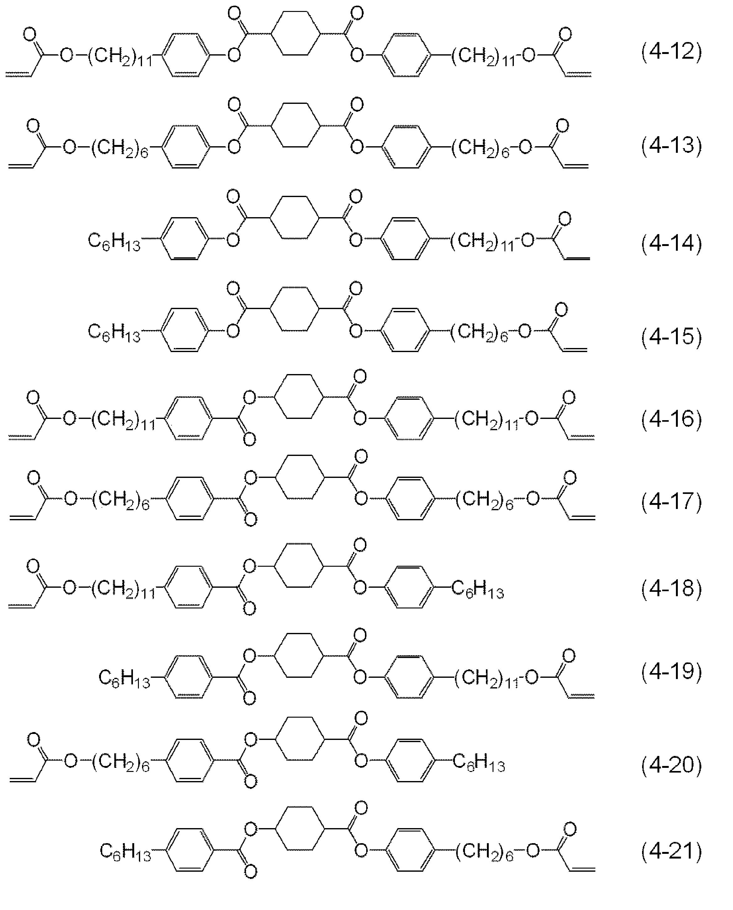


偏光子形成用組成物は、溶剤を含むことが好ましい。溶剤としては、二色性色素及び重合性液晶化合物を完全に溶解し得る溶剤が好ましい。また、偏光子形成用組成物に含まれる重合性液晶化合物の重合反応に不活性な溶剤であることが好ましい。 1-3. Solvent The composition for forming a polarizer preferably contains a solvent. As the solvent, a solvent capable of completely dissolving the dichroic dye and the polymerizable liquid crystal compound is preferable. Moreover, it is preferable that it is a solvent inactive to the polymerization reaction of the polymeric liquid crystal compound contained in the composition for polarizer formation.
本実施形態に係る偏光子形成用組成物は、添加剤を任意に含むことができる。添加剤としては、例えば、重合開始剤、光増感剤、重合禁止剤及びレベリング剤が挙げられる。 1-4. Additive The composition for forming a polarizer according to the present embodiment can optionally contain an additive. Examples of the additive include a polymerization initiator, a photosensitizer, a polymerization inhibitor, and a leveling agent.
偏光子形成用組成物は、重合開始剤を含有すると好ましい。重合開始剤は、重合性液晶化合物の重合反応を開始し得る化合物である。重合開始剤としては、低温条件下で、重合反応を開始できる点で、光重合開始剤が好ましい。具体的には、光の作用により活性ラジカル又は酸を発生する化合物が光重合開始剤として用いられる。当該光重合開始剤の中でも、光の作用により活性ラジカルを発生する重合開始剤がより好ましい。 1-4-1. Polymerization initiator The composition for forming a polarizer preferably contains a polymerization initiator. The polymerization initiator is a compound that can initiate a polymerization reaction of the polymerizable liquid crystal compound. As the polymerization initiator, a photopolymerization initiator is preferable in that the polymerization reaction can be initiated under low temperature conditions. Specifically, a compound that generates an active radical or an acid by the action of light is used as a photopolymerization initiator. Among the photopolymerization initiators, polymerization initiators that generate active radicals by the action of light are more preferable.
偏光子形成用組成物は、光重合開始剤を含有する場合、光増感剤を更に含有してもよい。光増感剤としては、例えば、キサントン及びチオキサントン等のキサントン化合物(例えば、2,4-ジエチルチオキサントン、2-イソプロピルチオキサントン等);アントラセン及びアルコキシ基含有アントラセン(例えば、ジブトキシアントラセン等)等のアントラセン化合物;フェノチアジン及びルブレンが挙げられる。 1-4-2. Photosensitizer When the composition for forming a polarizer contains a photopolymerization initiator, it may further contain a photosensitizer. Examples of the photosensitizer include anthracene such as xanthone compounds such as xanthone and thioxanthone (for example, 2,4-diethylthioxanthone and 2-isopropylthioxanthone); anthracene and anthracene containing an alkoxy group (for example, dibutoxyanthracene). Compounds; phenothiazine and rubrene.
偏光子形成用組成物は、重合性液晶化合物の重合反応を安定的に進行させるために、重合禁止剤を含有していてもよい。重合禁止剤により、重合性液晶化合物の重合反応の進行度合いをコントロールすることができる。 1-4-3. Polymerization inhibitor The composition for forming a polarizer may contain a polymerization inhibitor in order to allow the polymerization reaction of the polymerizable liquid crystal compound to proceed stably. The progress of the polymerization reaction of the polymerizable liquid crystal compound can be controlled by the polymerization inhibitor.
偏光子形成用組成物は、レベリング剤を含有すると好ましい。レベリング剤とは、偏光子形成用組成物の流動性を調整し、偏光子形成用組成物を塗布して得られる塗布膜をより平坦にする機能を有するものであり、界面活性剤等を挙げることができる。レベリング剤としては、例えば、ポリアクリレート化合物を主成分とするレベリング剤及びフッ素原子含有化合物を主成分とするレベリング剤が挙げられる。 1-4-4. Leveling agent It is preferable that the composition for forming a polarizer contains a leveling agent. The leveling agent has a function of adjusting the fluidity of the composition for forming a polarizer and flattening a coating film obtained by applying the composition for forming a polarizer, and includes a surfactant and the like. be able to. As a leveling agent, the leveling agent which has a polyacrylate compound as a main component and the leveling agent which has a fluorine atom containing compound as a main component is mentioned, for example.
偏光子形成用組成物を用いて偏光子を形成する方法について説明する。かかる方法では、偏光子形成用組成物を基材に、好ましくは透明基材に塗布することにより偏光子を形成する。 2. Method for Forming Polarizer A method for forming a polarizer using the composition for forming a polarizer will be described. In such a method, a polarizer is formed by applying a composition for forming a polarizer to a substrate, preferably a transparent substrate.
透明基材とは光、特に可視光を透過し得る程度の透明性を有する基材である。透明性とは、波長380~780nmに渡る光線に対しての透過率が80%以上となる特性をいう。具体的には、透明基材としては、例えば、ガラス基材及びプラスチック基材を挙げることができ、好ましくはプラスチック基材である。プラスチック基材を構成するプラスチックとしては、例えば、ポリエチレン、ポリプロピレン、ノルボルネン系ポリマー等のポリオレフィン;環状オレフィン系樹脂;ポリビニルアルコール;ポリエチレンテレフタレート;ポリメタクリル酸エステル;ポリアクリル酸エステル;トリアセチルセルロース、ジアセチルセルロース及びセルロースアセテートプロピオネート等のセルロースエステル;ポリエチレンナフタレート;ポリカーボネート;ポリスルホン;ポリエーテルスルホン;ポリエーテルケトン;ポリフェニレンスルフィド及びポリフェニレンオキシドが挙げられる。中でも、市場から容易に入手できたり、透明性に優れていたりする点から、とりわけ好ましくは、セルロースエステル、環状オレフィン系樹脂、ポリエチレンテレフタレート又はポリメタクリル酸エステルである。透明基材を用いて、偏光子を製造するに当たり、透明基材を運搬したり、保管したりする際に破れなどの破損を起こすことなく容易に取り扱える点で、透明基材に支持基材等を貼り付けておいてもよい。また、後述するが、偏光子から円偏光板を製造する際に、プラスチック基材に位相差性を付与することがある。この場合には、プラスチック基材に延伸処理などにより、位相差性を付与すればよい。 2-1. Base material A transparent base material is a base material having transparency to the extent that light, particularly visible light, can be transmitted. Transparency refers to the property that the transmittance with respect to a light beam having a wavelength of 380 to 780 nm is 80% or more. Specifically, examples of the transparent substrate include a glass substrate and a plastic substrate, and a plastic substrate is preferable. Examples of the plastic constituting the plastic substrate include polyolefins such as polyethylene, polypropylene and norbornene polymers; cyclic olefin resins; polyvinyl alcohol; polyethylene terephthalate; polymethacrylic acid esters; polyacrylic acid esters; triacetylcellulose and diacetylcellulose. And cellulose esters such as cellulose acetate propionate; polyethylene naphthalate; polycarbonate; polysulfone; polyethersulfone; polyetherketone; polyphenylene sulfide and polyphenylene oxide. Among these, cellulose ester, cyclic olefin resin, polyethylene terephthalate, or polymethacrylic acid ester is particularly preferable from the viewpoint that it can be easily obtained from the market or has excellent transparency. When manufacturing a polarizer using a transparent substrate, it can be handled easily without causing damage such as tearing when the transparent substrate is transported or stored. May be pasted. Moreover, although mentioned later, when manufacturing a circularly-polarizing plate from a polarizer, retardation may be provided to a plastic base material. In this case, the phase difference may be imparted to the plastic substrate by a stretching process or the like.
偏光子の製造に用いる基材には、配向層が形成されていることが好ましい。この場合、偏光子形成用組成物は配向層上に塗布することとなる。このため、配向層は、偏光子形成用組成物の塗布により溶解しない程度の溶剤耐性を有することが好ましい。また、溶剤の除去や液晶の配向のための加熱処理における耐熱性を有することが好ましい。配向層は、配向性ポリマーにより形成することができる。 2-2. Orientation layer It is preferable that the orientation layer is formed in the base material used for manufacture of a polarizer. In this case, the composition for forming a polarizer is applied on the alignment layer. For this reason, it is preferable that an orientation layer has solvent tolerance of the grade which is not melt | dissolved by application | coating of the composition for polarizer formation. Moreover, it is preferable to have heat resistance in the heat treatment for removing the solvent and aligning the liquid crystal. The alignment layer can be formed of an alignment polymer.
基材又は基材に形成された配向層上に、偏光子形成用組成物を塗布して塗布膜を得る。偏光子形成用組成物を塗布する方法としては例えば、配向性ポリマー組成物又は光配向層形成用組成物を基材に塗布する方法として例示した方法と同じ方法が挙げられる。 2-3. Manufacturing method of polarizing plate The composition for polarizer formation is apply | coated on the orientation layer formed in the base material or the base material, and a coating film is obtained. Examples of the method for applying the composition for forming a polarizer include the same method as the method exemplified as a method for applying an alignment polymer composition or a composition for forming a photo-alignment layer to a substrate.
-3≦ 色度a* ≦3 (1F)
-3≦ 色度b* ≦3 (2F) The polarizer according to the present embodiment is excellent in neutral hue. With a polarizer having excellent neutral hue, the color coordinate a * value and b * value in the L * a * b * (Lab) color system satisfy the relationship of the following formulas (1F) and (2F): Is.
-3 ≦ chromaticity a * ≦ 3 (1F)
-3 ≦ chromaticity b * ≦ 3 (2F)
-3≦ 直交a* ≦3 (1F’)
-3≦ 直交b* ≦3 (2F’) In the hue of the polarizer, when two polarizers are overlapped so that the absorption axes are orthogonal to each other, the hue at that time is obtained in the same manner as described above, and "orthogonal a *" and "orthogonal b *" are calculated. More preferably, each of the orthogonal a * and the orthogonal b * satisfies the relationship of the following expressions (1F ′) and (2F ′). These orthogonal a * and orthogonal b * are indexes indicating whether or not the hue of black display is neutral in a display device including a polarizer. The closer both the orthogonal a * and the orthogonal b * are to 0 (zero), the better black display without coloring can be obtained.
-3 ≦ orthogonal a * ≦ 3 (1F ′)
-3 ≦ orthogonal b * ≦ 3 (2F ′)
Δn(450)/Δn(550)≦1.00 (II)
1.00≦Δn(650)/Δn(550) (III)
このような逆波長分散特性を示す位相差フィルムは、特許第5463666号公報に記載の方法により作製することができる。 The birefringence for light with a wavelength of 450 nm, the birefringence with respect to light with a wavelength of 550 nm, and the birefringence with respect to light with a wavelength of 650 nm of the quarter wave plate used as a retardation film are expressed by the following formulas (II) and (III). It is preferable to have reverse wavelength dispersion satisfying the relationship shown. In the formula, Δn (λ) represents a birefringence for light having a wavelength of λ nm.
Δn (450) / Δn (550) ≦ 1.00 (II)
1.00 ≦ Δn (650) / Δn (550) (III)
A retardation film exhibiting such reverse wavelength dispersion characteristics can be produced by the method described in Japanese Patent No. 5463666.
偏光板は、さまざまな表示装置に用いることができる。表示装置とは、表示素子を有する装置であり、発光源として発光素子又は発光装置を含む。表示装置としては、例えば、液晶表示装置、有機エレクトロルミネッセンス(EL)表示装置、無機エレクトロルミネッセンス(EL)表示装置、電子放出表示装置(例えば電場放出表示装置(FED)、表面電界放出表示装置(SED))、電子ペーパー(電子インクや電気泳動素子を用いた表示装置、プラズマ表示装置、投射型表示装置(例えばグレーティングライトバルブ(GLV)表示装置、デジタルマイクロミラーデバイス(DMD)を有する表示装置)及び圧電セラミックディスプレイが挙げられる。液晶表示装置としては、例えば、透過型液晶表示装置、半透過型液晶表示装置、反射型液晶表示装置、直視型液晶表示装置及び投写型液晶表示装置が挙げられる。これらの表示装置は、2次元画像を表示する表示装置であってもよいし、3次元画像を表示する立体表示装置であってもよい。本実施形態の偏光板は、特に有機EL表示装置又は無機EL表示装置の表示装置に有効に用いることができる。 4). Applications of polarizing plates Polarizing plates can be used in various display devices. A display device is a device having a display element and includes a light-emitting element or a light-emitting device as a light-emitting source. Examples of the display device include a liquid crystal display device, an organic electroluminescence (EL) display device, an inorganic electroluminescence (EL) display device, an electron emission display device (for example, a field emission display device (FED), a surface field emission display device (SED). )), Electronic paper (display device using electronic ink or electrophoretic element, plasma display device, projection display device (eg, display device having a grating light valve (GLV) display device, digital micromirror device (DMD)), and Examples of the liquid crystal display device include a transmissive liquid crystal display device, a transflective liquid crystal display device, a reflective liquid crystal display device, a direct view liquid crystal display device, and a projection liquid crystal display device. The display device may be a display device that displays a two-dimensional image. Stone, or it may be a three-dimensional display apparatus for displaying a three dimensional image. The polarizing plate of the present embodiment can be effectively used in particular display device of the organic EL display device or an inorganic EL display device.
偏光子の吸光度を、以下のようにして測定した。二色性色素の配向方向(吸収軸方向)の吸光度(A1)及び偏光子の面内であって配向垂直方向(透過軸方向)の吸光度(A2)を、分光光度計(島津製作所株式会社製 UV-3150)に偏光子付フォルダーをセットした装置を使用して、ダブルビーム法により2nmステップ380~680nmの波長範囲で測定した。尚、偏光板の表面反射による光損失分の寄与を除去するために、測定サンプルをセットした後に、光吸収の無い800nmでゼロ点補正してから測定を実施した。 (Absorbance measurement)
The absorbance of the polarizer was measured as follows. The absorbance (A1) in the orientation direction (absorption axis direction) of the dichroic dye and the absorbance (A2) in the orientation plane (transmission axis direction) in the plane of the polarizer are measured with a spectrophotometer (manufactured by Shimadzu Corporation). UV-3150) was set in a wavelength range of 2 nm steps 380 to 680 nm by a double beam method using an apparatus in which a folder with a polarizer was set. In addition, in order to remove the contribution of the light loss due to the surface reflection of the polarizing plate, after setting the measurement sample, the measurement was performed after correcting the zero point at 800 nm with no light absorption.
粘着剤を介して、偏光板におけるトリアセチルセルロースフィルム面を、ガラス基板に貼合した。そして、23℃において吸収軸方向の吸光度A1を上記の方法により測定した(A1(23℃))。その後、85℃のオーブンに100時間投入し、取り出した後に再び上記の方法により吸光度測定を実施した。下記式(I)により吸光度保持率(%)を算出した。
吸光度保持率(%)=A1(85℃)/A1(23℃)×100 (I)
式中、A1(85℃)は85℃の耐熱オーブン中で偏光板を100時間保持した後の吸収軸方向の吸光度、A1(23℃)は耐熱性試験前に23℃で測定した際の吸収軸方向の吸光度を示す。 [Heat resistance evaluation]
The triacetylcellulose film surface in a polarizing plate was bonded to the glass substrate through the adhesive. And the light absorbency A1 of the absorption-axis direction was measured by said method at 23 degreeC (A1 (23 degreeC)). Thereafter, the sample was put into an 85 ° C. oven for 100 hours, and after taking out, the absorbance was measured again by the above method. Absorbance retention (%) was calculated by the following formula (I).
Absorbance retention (%) = A1 (85 ° C.) / A1 (23 ° C.) × 100 (I)
In the formula, A1 (85 ° C.) is the absorbance in the absorption axis direction after holding the polarizing plate in an 85 ° C. heat-resistant oven for 100 hours, and A 1 (23 ° C.) is the absorption when measured at 23 ° C. before the heat resistance test. The absorbance in the axial direction is shown.
偏光板をミクロトームで切削した後、カーボン蒸着を施した断面を走査型透過電子顕微鏡(STEM、電界放射型走査電子顕微鏡(FE-STEM)、型番:「S-5500」、日立製作所製)により観察することで、偏光子(偏光層)の厚みを測定した。 [Film thickness measurement]
After the polarizing plate is cut with a microtome, the carbon-deposited section is observed with a scanning transmission electron microscope (STEM, field emission scanning electron microscope (FE-STEM), model number: “S-5500”, manufactured by Hitachi, Ltd.) Thus, the thickness of the polarizer (polarizing layer) was measured.
[光配向層形成用組成物の製造]
下記式(3)で表される光配向性材料(2部)と、溶剤としてo-キシレン(98部)とを混合し、得られた混合物を80℃で1時間攪拌することにより、光配向層形成用組成物を得た。下記式(3)で表される光配向性材料は、特開2013-33248号公報記載の方法で合成した。

[Production of composition for forming photo-alignment layer]
A photo-alignment material (2 parts) represented by the following formula (3) and o-xylene (98 parts) as a solvent were mixed, and the resulting mixture was stirred at 80 ° C. for 1 hour to produce photo-alignment. A layer forming composition was obtained. The photoalignable material represented by the following formula (3) was synthesized by the method described in JP2013-33248A.
下記の成分を混合し、80℃で1時間攪拌することで、偏光子形成用組成物を得た。
重合性液晶化合物;下記式(4-6)で表される化合物 75部
下記式(4-7)で表される化合物 25部

下記式(2-15)で表されるYellow色素 1.3部
下記式(2-27)で表されるCyan色素 1.3部

レベリング剤;ポリアクリレート化合物(BYK-361N;BYK-Chemie社製) 1.2部
溶剤;キシレン 250部 (Production of composition for forming a polarizer)
The following components were mixed and stirred at 80 ° C. for 1 hour to obtain a composition for forming a polarizer.
Polymerizable liquid crystal compound: 75 parts of a compound represented by the following formula (4-6) 25 parts of a compound represented by the following formula (4-7)
幅600mmのトリアセチルセルロースフィルム(コニカミノルタ社製KC4UY-TAC 40μm)ロールを8m/分の速度で連続的に巻出し、フィルム表面にプラズマ処理を施した後に、スロットダイコーターにより光配向層形成用組成物を16mL/分の流量で吐出して、フィルム中央部の幅400mm範囲に塗布し、第一塗布膜を形成した。さらに、100℃に設定した通風乾燥炉中に2分間搬送させることで溶剤を除去し、第一乾燥膜を形成した。その後、フィルム搬送方向に対して45°方向に偏光した偏光UV光を該第一乾燥膜に20mJ/cm2(313nm基準)の強度となるように照射することで配向規制力を付与して、光配向層付き基材フィルムを作製した。光配向層面上に、スロットダイコーターにより偏光子形成用組成物を30mL/分の流量で吐出して、フィルム中央部の幅400mm範囲に塗布し、第二塗布膜を形成した。さらに、110℃に設定した通風乾燥炉中に2分間搬送させることで溶剤を除去し、第二乾燥膜を形成した。その後、UV光を500mJ/cm2(365nm基準)で照射して重合性液晶化合物を重合硬化させることで偏光子を形成した。その後、連続的にロール状に巻き上げることで、45°方向に吸収軸を有する偏光フィルムロールを作製した。このように作製した長尺の偏光フィルムロールから3cm角の大きさに切りだしたものを偏光板として用いて種々評価を行った。偏光子の膜厚、各二色性色素の極大吸収波長における吸光度及び吸光度保持率を表1に示す。 [Production of polarizing film (polarizing plate)]
A roll of 600 mm wide triacetyl cellulose film (Konica Minolta KC4UY-TAC 40 μm) is continuously unwound at a speed of 8 m / min. After the plasma treatment is performed on the film surface, a slot die coater is used to form a photo-alignment layer. The composition was discharged at a flow rate of 16 mL / min and applied to a width of 400 mm in the center of the film to form a first coating film. Furthermore, the solvent was removed by carrying for 2 minutes in the ventilation drying furnace set to 100 degreeC, and the 1st dry film | membrane was formed. Then, the alignment regulation force is imparted by irradiating the first dry film with polarized UV light polarized in a 45 ° direction with respect to the film transport direction so as to have an intensity of 20 mJ / cm 2 (313 nm reference). A substrate film with a photo-alignment layer was produced. On the surface of the photo-alignment layer, the composition for forming a polarizer was discharged at a flow rate of 30 mL / min with a slot die coater and applied to the width of 400 mm in the center of the film to form a second coating film. Furthermore, the solvent was removed by carrying for 2 minutes in the ventilation drying furnace set to 110 degreeC, and the 2nd dry film | membrane was formed. Thereafter, UV light was irradiated at 500 mJ / cm 2 (365 nm standard) to polymerize and cure the polymerizable liquid crystal compound, thereby forming a polarizer. Then, the polarizing film roll which has an absorption axis in a 45 degree direction was produced by winding up continuously in roll shape. Various evaluations were performed using the long polarizing film rolls produced in this manner and cut into 3 cm square sizes as polarizing plates. Table 1 shows the film thickness of the polarizer, the absorbance and the absorbance retention at the maximum absorption wavelength of each dichroic dye.
偏光子形成用組成物の塗布流量を15mL/分とした以外は実施例1と同様にして、偏光フィルムロールを作製し、実施例1と同様の測定を実施した。 Example 2
A polarizing film roll was produced in the same manner as in Example 1 except that the application flow rate of the composition for forming a polarizer was 15 mL / min, and the same measurement as in Example 1 was performed.
二色性色素の混合量を以下のように変更した以外は実施例1と同様にして、偏光フィルムロールを作製し、実施例1と同様の測定を実施した。
式(2-18)で表されるMagenta色素 2.3部
式(2-15)で表されるYellow色素 2.3部
式(2-27)で表されるCyan色素 2.3部 Example 3
A polarizing film roll was produced in the same manner as in Example 1 except that the mixing amount of the dichroic dye was changed as follows, and the same measurement as in Example 1 was performed.
Magenta dye represented by formula (2-18) 2.3 parts Yellow dye represented by formula (2-15) 2.3 parts Cyan dye represented by formula (2-27) 2.3 parts
二色性色素の混合量を以下のように変更した以外は実施例2と同様にして、偏光フィルムロールを作製し、実施例2と同様の測定を実施した。
式(2-18)で表されるMagenta色素 2.3部
式(2-15)で表されるYellow色素 2.3部
式(2-27)で表されるCyan色素 2.3部 Example 4
A polarizing film roll was produced in the same manner as in Example 2 except that the mixing amount of the dichroic dye was changed as follows, and the same measurement as in Example 2 was performed.
Magenta dye represented by formula (2-18) 2.3 parts Yellow dye represented by formula (2-15) 2.3 parts Cyan dye represented by formula (2-27) 2.3 parts
〔ヨウ素PVA偏光板の作製〕
平均重合度約2400、ケン化度99.9モル%以上で厚さ75μmのポリビニルアルコールフィルムを、乾式で約5.5倍に一軸延伸し、さらに緊張状態を保ったまま、60℃の純水に60秒間浸漬した後、ヨウ素/ヨウ化カリウム/水の重量比が0.05/5/100の水溶液に23℃で30秒間浸漬した。その後、ヨウ化カリウム/ホウ酸/水の重量比が8.5/8.5/100の水溶液に72℃で300秒間浸漬した。引き続き23℃の純水で15秒間洗浄した後、70℃で2分間乾燥して、ポリビニルアルコール樹脂にヨウ素が吸着配向された偏光子を得た。この偏光子を接触式の膜厚計により測定したところ、25μmであった。このようにして得られた偏光子の両面に、カルボキシル基変性ポリビニルアルコール〔クラレ株式会社製 クラレポバールKL318〕3部と、水溶性ポリアミドエポキシ樹脂〔住化ケムテックス株式会社製 スミレーズレジン(登録商標)650(固形分濃度30%の水溶液)〕1.5部から作製したポリビニルアルコール系接着剤を介して、ケン化処理を施したトリアセチルセルロースフィルム(コニカミノルタ社製KC4UY-TAC 40μm)で両面を保護して偏光板を作製した。この偏光板をサンプリングし、実施例1と同様の測定を実施したところ、474nmを極大吸収波長としてI3-PVA錯体起因の光吸収が、594nmを極大吸収波長としてI5-PVA錯体起因の光吸収が測定された。 Comparative Example 1
[Production of iodine PVA polarizing plate]
A polyvinyl alcohol film having an average degree of polymerization of about 2400 and a saponification degree of 99.9 mol% or more and a thickness of 75 μm is uniaxially stretched about 5.5 times in a dry manner and further maintained at 60 ° C. with pure water at 60 ° C. And then immersed in an aqueous solution having a weight ratio of iodine / potassium iodide / water of 0.05 / 5/100 at 23 ° C. for 30 seconds. Then, it was immersed in an aqueous solution having a weight ratio of potassium iodide / boric acid / water of 8.5 / 8.5 / 100 at 72 ° C. for 300 seconds. Subsequently, it was washed with pure water at 23 ° C. for 15 seconds and then dried at 70 ° C. for 2 minutes to obtain a polarizer in which iodine was adsorbed and oriented on a polyvinyl alcohol resin. It was 25 micrometers when this polarizer was measured with the contact-type film thickness meter. On both sides of the polarizer thus obtained, 3 parts of a carboxyl group-modified polyvinyl alcohol [Kuraray Co., Ltd., Kuraray Poval KL318] and a water-soluble polyamide epoxy resin [Sumika Chemtex Co., Ltd., Sumire's Resin (registered trademark)] 650 (aqueous solution with a solid content concentration of 30%)] Both surfaces were coated with a saponified triacetyl cellulose film (KC4UY-TAC 40 μm manufactured by Konica Minolta Co., Ltd.) through a polyvinyl alcohol adhesive prepared from 1.5 parts. A polarizing plate was produced with protection. This polarizing plate was sampled, and the same measurement as in Example 1 was performed. As a result, light absorption caused by the I3-PVA complex with 474 nm as the maximum absorption wavelength and light absorption caused by the I5-PVA complex with 594 nm as the maximum absorption wavelength were observed. Measured.
ヨウ素/ヨウ化カリウム/水の重量比が0.06/6/100の水溶液に23℃で30秒間浸漬した以外は比較例1と同様にして、偏光フィルムを作製した。この偏光フィルムをサンプリングし、実施例1と同様の測定を実施したところ、474nmを極大吸収波長としてI3-PVA錯体起因の光吸収が、594nmを極大吸収波長としてI5-PVA錯体起因の光吸収が測定された。 Comparative Example 2
A polarizing film was produced in the same manner as in Comparative Example 1 except that it was immersed in an aqueous solution having a weight ratio of iodine / potassium iodide / water of 0.06 / 6/100 at 23 ° C. for 30 seconds. This polarizing film was sampled and the same measurement as in Example 1 was carried out. As a result, light absorption caused by the I3-PVA complex with 474 nm as the maximum absorption wavelength and light absorption due to the I5-PVA complex with 594 nm as the maximum absorption wavelength were observed. Measured.
ヨウ素/ヨウ化カリウム/水の重量比が0.06/6/100の水溶液に23℃で40秒間浸漬した以外は比較例1と同様にして、偏光フィルムを作製した。この偏光フィルムをサンプリングし、実施例1と同様の測定を実施したところ、474nmを極大吸収波長としてI3-PVA錯体起因の光吸収が、594nmを極大吸収波長としてI5-PVA錯体起因の光吸収が測定された。 Comparative Example 3
A polarizing film was produced in the same manner as in Comparative Example 1 except that it was immersed in an aqueous solution having a weight ratio of iodine / potassium iodide / water of 0.06 / 6/100 at 23 ° C. for 40 seconds. This polarizing film was sampled and the same measurement as in Example 1 was carried out. As a result, light absorption caused by the I3-PVA complex with 474 nm as the maximum absorption wavelength and light absorption due to the I5-PVA complex with 594 nm as the maximum absorption wavelength were observed. Measured.

Claims (8)
- 基材と、偏光子とを備えた偏光板であって、
前記偏光子は、二色性色素が配向している厚さ5μm以下の偏光層を有し、
前記偏光子の波長380~760nmにおける、吸収軸方向の吸光度(A1)が0.3以上1.5以下であり、透過軸方向の吸光度(A2)が0.001以上0.15以下である、偏光板。 A polarizing plate comprising a substrate and a polarizer,
The polarizer has a polarizing layer having a thickness of 5 μm or less in which the dichroic dye is oriented,
In the wavelength range of 380 to 760 nm of the polarizer, the absorbance (A1) in the absorption axis direction is 0.3 or more and 1.5 or less, and the absorbance (A2) in the transmission axis direction is 0.001 or more and 0.15 or less. Polarizer. - 前記二色性色素が、有機染料である、請求項1に記載の偏光板。 The polarizing plate according to claim 1, wherein the dichroic dye is an organic dye.
- 前記偏光層が、重合性液晶化合物の重合体を含む、請求項1又は2に記載の偏光板。 The polarizing plate according to claim 1 or 2, wherein the polarizing layer contains a polymer of a polymerizable liquid crystal compound.
- 前記重合性液晶化合物が、スメクチック液晶相を示す化合物である、請求項3に記載の偏光板。 The polarizing plate according to claim 3, wherein the polymerizable liquid crystal compound is a compound exhibiting a smectic liquid crystal phase.
- 前記重合性液晶化合物が、高次スメクチック液晶相を示す化合物である、請求項4に記載の偏光板。 The polarizing plate according to claim 4, wherein the polymerizable liquid crystal compound is a compound exhibiting a high-order smectic liquid crystal phase.
- 前記偏光子が、X線回折測定においてブラッグピークを示す、請求項1~5のいずれか一項に記載の偏光板。 The polarizing plate according to any one of claims 1 to 5, wherein the polarizer exhibits a Bragg peak in X-ray diffraction measurement.
- 請求項1~6のいずれか一項に記載の偏光板と、1/4波長板とを含む円偏光板。 A circularly polarizing plate comprising the polarizing plate according to any one of claims 1 to 6 and a quarter-wave plate.
- 前記1/4波長板の波長450nmの光に対する複屈折率、波長550nmの光に対する複屈折率及び波長650nmの光に対する複屈折率が、下記式(II)及び(III)で示される関係を満足する逆波長分散性を有する、請求項7に記載の円偏光板。
Δn(450)/Δn(550)≦1.00 (II)
1.00≦Δn(650)/Δn(550) (III)
(式中、Δn(λ)は波長λnmの光に対する複屈折率を表す。) The birefringence of the quarter-wave plate with respect to light having a wavelength of 450 nm, the birefringence with respect to light with a wavelength of 550 nm, and the birefringence with respect to light with a wavelength of 650 nm satisfy the relationship represented by the following formulas (II) and (III). The circularly polarizing plate according to claim 7, which has reverse wavelength dispersion.
Δn (450) / Δn (550) ≦ 1.00 (II)
1.00 ≦ Δn (650) / Δn (550) (III)
(In the formula, Δn (λ) represents a birefringence for light having a wavelength of λ nm.)
Priority Applications (5)
| Application Number | Priority Date | Filing Date | Title |
|---|---|---|---|
| KR1020177028837A KR102428495B1 (en) | 2015-03-16 | 2016-03-08 | Polarizing plate and circularly polarizing plate |
| CN201680014684.8A CN107430232B (en) | 2015-03-16 | 2016-03-08 | Polarizing plate and circularly polarizing plate |
| CN202010885121.4A CN111812765B (en) | 2015-03-16 | 2016-03-08 | Polarizing plate and circularly polarizing plate |
| US15/558,756 US10690953B2 (en) | 2015-03-16 | 2016-03-08 | Polarizing plate and circularly polarizing plate |
| US16/864,192 US20200264460A1 (en) | 2015-03-16 | 2020-05-01 | Polarizing plate and circularly polarizing plate |
Applications Claiming Priority (2)
| Application Number | Priority Date | Filing Date | Title |
|---|---|---|---|
| JP2015-051786 | 2015-03-16 | ||
| JP2015051786A JP6483486B2 (en) | 2015-03-16 | 2015-03-16 | Polarizing plate and circularly polarizing plate |
Related Child Applications (2)
| Application Number | Title | Priority Date | Filing Date |
|---|---|---|---|
| US15/558,756 A-371-Of-International US10690953B2 (en) | 2015-03-16 | 2016-03-08 | Polarizing plate and circularly polarizing plate |
| US16/864,192 Continuation US20200264460A1 (en) | 2015-03-16 | 2020-05-01 | Polarizing plate and circularly polarizing plate |
Publications (1)
| Publication Number | Publication Date |
|---|---|
| WO2016147960A1 true WO2016147960A1 (en) | 2016-09-22 |
Family
ID=56918921
Family Applications (1)
| Application Number | Title | Priority Date | Filing Date |
|---|---|---|---|
| PCT/JP2016/057221 WO2016147960A1 (en) | 2015-03-16 | 2016-03-08 | Polarizing plate and circularly polarizing plate |
Country Status (6)
| Country | Link |
|---|---|
| US (2) | US10690953B2 (en) |
| JP (1) | JP6483486B2 (en) |
| KR (1) | KR102428495B1 (en) |
| CN (2) | CN107430232B (en) |
| TW (1) | TWI686632B (en) |
| WO (1) | WO2016147960A1 (en) |
Cited By (1)
| Publication number | Priority date | Publication date | Assignee | Title |
|---|---|---|---|---|
| WO2021251122A1 (en) * | 2020-06-12 | 2021-12-16 | 住友化学株式会社 | Polarizing film and elliptical polarizing plate |
Families Citing this family (15)
| Publication number | Priority date | Publication date | Assignee | Title |
|---|---|---|---|---|
| CN105807359B (en) * | 2016-05-30 | 2017-04-05 | 京东方科技集团股份有限公司 | Line polarisation layer, rotatory polarization layer, flexible display apparatus and preparation method thereof |
| JP2018072710A (en) * | 2016-11-02 | 2018-05-10 | 日東電工株式会社 | Polarization plate |
| JP2018124467A (en) * | 2017-02-02 | 2018-08-09 | 住友化学株式会社 | Composite polarizing plate and liquid crystal display device |
| CN111527426B (en) | 2017-12-28 | 2022-06-28 | 富士胶片株式会社 | Polarizer and image display device |
| CN111819476B (en) * | 2017-12-28 | 2022-05-13 | 富士胶片株式会社 | Polarizer and image display device |
| KR102383293B1 (en) | 2018-01-25 | 2022-04-05 | 주식회사 엘지화학 | Multi-layer liquid crystal film, polarizing plate and method for manufacturing of polarizing plate |
| CN108490680B (en) * | 2018-03-29 | 2021-03-23 | 武汉华星光电技术有限公司 | Liquid crystal panel and manufacturing method thereof |
| JP7163066B2 (en) * | 2018-05-22 | 2022-10-31 | 日東電工株式会社 | Circularly polarizing plate and image display device |
| WO2020004106A1 (en) * | 2018-06-27 | 2020-01-02 | 富士フイルム株式会社 | Polarizer and image display device |
| JP6800359B2 (en) | 2019-03-05 | 2020-12-16 | 住友化学株式会社 | Laminate |
| JP7271721B2 (en) * | 2019-12-17 | 2023-05-11 | 富士フイルム株式会社 | organic electroluminescence display |
| WO2021131792A1 (en) | 2019-12-26 | 2021-07-01 | 富士フイルム株式会社 | Light absorption anisotropic layer, laminate, optical film, image display device, back light module |
| KR20230048011A (en) | 2020-08-03 | 2023-04-10 | 미쯔비시 케미컬 주식회사 | Compound, composition for anisotropic dye film containing the compound, anisotropic dye film, and optical element |
| US20230273358A1 (en) * | 2020-08-04 | 2023-08-31 | Samsung Sdi Co., Ltd. | Polarizing plate and optical display device comprising same |
| KR20220022410A (en) * | 2020-08-18 | 2022-02-25 | 동우 화인켐 주식회사 | Polarizing Plate for Antireflection and Display Device Comprising the Same |
Citations (3)
| Publication number | Priority date | Publication date | Assignee | Title |
|---|---|---|---|---|
| JP2013101328A (en) * | 2011-10-12 | 2013-05-23 | Sumitomo Chemical Co Ltd | Polarizing film, circularly polarizing plate and their manufacturing method |
| JP2013109090A (en) * | 2011-11-18 | 2013-06-06 | Sumitomo Chemical Co Ltd | Polarizing film, circularly polarizing plate, and organic el image display device using these |
| JP2013148883A (en) * | 2011-12-20 | 2013-08-01 | Sumitomo Chemical Co Ltd | Composition for forming polarizing film and polarizing film |
Family Cites Families (23)
| Publication number | Priority date | Publication date | Assignee | Title |
|---|---|---|---|---|
| JPS5083482A (en) | 1973-11-26 | 1975-07-05 | ||
| JPS5838756A (en) | 1981-08-31 | 1983-03-07 | Gosei Senriyou Gijutsu Kenkyu Kumiai | Disazo dye for polyester fiber |
| CA1269555A (en) * | 1984-11-16 | 1990-05-29 | Sumitomo Chemical Company, Limited | Light-polarizing film |
| JPS63301850A (en) | 1988-01-13 | 1988-12-08 | Nippon Kanko Shikiso Kenkyusho:Kk | Azo compound and dichromic pigment for liquid crystal consisting of said azo compound |
| JPH02113920A (en) | 1988-10-25 | 1990-04-26 | Mitsubishi Kasei Corp | Production of stretched film or sheet |
| JPH0527270A (en) * | 1991-07-24 | 1993-02-05 | Mitsubishi Kasei Corp | Light control element |
| US5280373A (en) * | 1991-07-24 | 1994-01-18 | Mitsubishi Kasei Corporation | Light modulating device including a liquid crystal, a polymer and dichroic dyes having maximum absorption in the different wavelength regions |
| JP2761453B2 (en) | 1993-11-17 | 1998-06-04 | 出光興産株式会社 | Organic EL element and organic EL panel |
| JPH11149015A (en) * | 1997-11-14 | 1999-06-02 | Nitto Denko Corp | Laminated wavelength plate, circularly polarized light plate and liquid crystal display device |
| JP3459779B2 (en) * | 1998-10-30 | 2003-10-27 | 帝人株式会社 | Phase difference plate |
| JP2002185983A (en) | 2000-12-13 | 2002-06-28 | Arisawa Mfg Co Ltd | Film for forming 3d video display object and 3d video display device |
| EP2159611B1 (en) | 2003-11-06 | 2018-01-03 | Sumitomo Chemical Company, Limited | Polymerizable liquid crystal and oriented polymer film |
| KR100881982B1 (en) * | 2006-09-08 | 2009-02-05 | 주식회사 엘지화학 | Dichroic Dye for Polarization Film, Composition Comprising the Same for Polarization Film, Method for Forming Polarization Plate and Polarization Plate Prepared Thereby |
| JP5202889B2 (en) * | 2007-06-29 | 2013-06-05 | 日東電工株式会社 | Multilayer polarizing plate, method for producing the same, and liquid crystal display device |
| JP2009103828A (en) | 2007-10-22 | 2009-05-14 | Hitachi Displays Ltd | Liquid crystal display device |
| JP4605206B2 (en) * | 2007-11-06 | 2011-01-05 | ソニー株式会社 | Liquid crystal display device |
| JP5463666B2 (en) | 2007-12-28 | 2014-04-09 | 住友化学株式会社 | Compound, optical film and method for producing optical film |
| JP5300776B2 (en) * | 2010-03-31 | 2013-09-25 | 富士フイルム株式会社 | Polarizing film, display device, and manufacturing method thereof |
| JP5511730B2 (en) * | 2010-09-03 | 2014-06-04 | 日東電工株式会社 | Continuous manufacturing method and apparatus for optical panel assembly |
| TW201311743A (en) | 2011-07-07 | 2013-03-16 | Sumitomo Chemical Co | Photoreactive liquid crystal alignment agent, liquid crystal alignment element and preparation method thereof |
| KR102129135B1 (en) * | 2012-02-28 | 2020-07-01 | 스미또모 가가꾸 가부시키가이샤 | Polarizing film, circular polarizing plate and method of producing the same |
| TWI645962B (en) * | 2013-08-09 | 2019-01-01 | 住友化學股份有限公司 | Optically anisotropic sheet |
| KR20150093591A (en) * | 2014-02-07 | 2015-08-18 | 스미또모 가가꾸 가부시키가이샤 | Process for producing long polarizing film |
-
2015
- 2015-03-16 JP JP2015051786A patent/JP6483486B2/en active Active
-
2016
- 2016-03-08 CN CN201680014684.8A patent/CN107430232B/en active Active
- 2016-03-08 KR KR1020177028837A patent/KR102428495B1/en active IP Right Grant
- 2016-03-08 US US15/558,756 patent/US10690953B2/en active Active
- 2016-03-08 WO PCT/JP2016/057221 patent/WO2016147960A1/en active Application Filing
- 2016-03-08 CN CN202010885121.4A patent/CN111812765B/en active Active
- 2016-03-16 TW TW105108145A patent/TWI686632B/en active
-
2020
- 2020-05-01 US US16/864,192 patent/US20200264460A1/en not_active Abandoned
Patent Citations (3)
| Publication number | Priority date | Publication date | Assignee | Title |
|---|---|---|---|---|
| JP2013101328A (en) * | 2011-10-12 | 2013-05-23 | Sumitomo Chemical Co Ltd | Polarizing film, circularly polarizing plate and their manufacturing method |
| JP2013109090A (en) * | 2011-11-18 | 2013-06-06 | Sumitomo Chemical Co Ltd | Polarizing film, circularly polarizing plate, and organic el image display device using these |
| JP2013148883A (en) * | 2011-12-20 | 2013-08-01 | Sumitomo Chemical Co Ltd | Composition for forming polarizing film and polarizing film |
Cited By (1)
| Publication number | Priority date | Publication date | Assignee | Title |
|---|---|---|---|---|
| WO2021251122A1 (en) * | 2020-06-12 | 2021-12-16 | 住友化学株式会社 | Polarizing film and elliptical polarizing plate |
Also Published As
| Publication number | Publication date |
|---|---|
| CN111812765A (en) | 2020-10-23 |
| CN107430232A (en) | 2017-12-01 |
| KR102428495B1 (en) | 2022-08-02 |
| KR20170127013A (en) | 2017-11-20 |
| CN111812765B (en) | 2022-08-26 |
| JP2016170368A (en) | 2016-09-23 |
| US20180067348A1 (en) | 2018-03-08 |
| US20200264460A1 (en) | 2020-08-20 |
| JP6483486B2 (en) | 2019-03-13 |
| TWI686632B (en) | 2020-03-01 |
| US10690953B2 (en) | 2020-06-23 |
| CN107430232B (en) | 2020-09-18 |
| TW201640158A (en) | 2016-11-16 |
Similar Documents
| Publication | Publication Date | Title |
|---|---|---|
| JP6483486B2 (en) | Polarizing plate and circularly polarizing plate | |
| TWI645974B (en) | Laminated body | |
| KR102359336B1 (en) | Process for producing long retardation film | |
| JP2024051161A (en) | Cured liquid crystal film, optical film including the cured liquid crystal film, and display device | |
| US20160146995A1 (en) | Optical film | |
| US20160124131A1 (en) | Optically anisotropic film and method for producing optically anisotropic film | |
| JP2019194685A (en) | Polarizing plate | |
| WO2016147956A1 (en) | Polarizing plate and circularly polarizing plate | |
| WO2019082745A1 (en) | Polarizing film and method for manufacturing same | |
| CN106367079B (en) | Composition and display device | |
| WO2019208299A1 (en) | Polarizing plate | |
| CN114051586A (en) | Long film | |
| CN113661420A (en) | Laminate and composition for forming vertically aligned liquid crystal cured film | |
| CN112585513B (en) | Laminate comprising horizontally aligned liquid crystal cured film | |
| JP6010910B2 (en) | Composition and optical film | |
| CN112513697A (en) | Horizontally aligned liquid crystal cured film and laminate comprising same |
Legal Events
| Date | Code | Title | Description |
|---|---|---|---|
| 121 | Ep: the epo has been informed by wipo that ep was designated in this application |
Ref document number: 16764790 Country of ref document: EP Kind code of ref document: A1 |
|
| WWE | Wipo information: entry into national phase |
Ref document number: 15558756 Country of ref document: US |
|
| NENP | Non-entry into the national phase |
Ref country code: DE |
|
| ENP | Entry into the national phase |
Ref document number: 20177028837 Country of ref document: KR Kind code of ref document: A |
|
| 122 | Ep: pct application non-entry in european phase |
Ref document number: 16764790 Country of ref document: EP Kind code of ref document: A1 |