WO2016147855A1 - Information processing device, screen switching method, program, and transmission system - Google Patents
Information processing device, screen switching method, program, and transmission system Download PDFInfo
- Publication number
- WO2016147855A1 WO2016147855A1 PCT/JP2016/056292 JP2016056292W WO2016147855A1 WO 2016147855 A1 WO2016147855 A1 WO 2016147855A1 JP 2016056292 W JP2016056292 W JP 2016056292W WO 2016147855 A1 WO2016147855 A1 WO 2016147855A1
- Authority
- WO
- WIPO (PCT)
- Prior art keywords
- image
- switching
- communication
- display
- transmission
- Prior art date
Links
Images


Classifications
-
- H—ELECTRICITY
- H04—ELECTRIC COMMUNICATION TECHNIQUE
- H04B—TRANSMISSION
- H04B17/00—Monitoring; Testing
- H04B17/30—Monitoring; Testing of propagation channels
- H04B17/309—Measuring or estimating channel quality parameters
- H04B17/318—Received signal strength
-
- G—PHYSICS
- G06—COMPUTING; CALCULATING OR COUNTING
- G06F—ELECTRIC DIGITAL DATA PROCESSING
- G06F3/00—Input arrangements for transferring data to be processed into a form capable of being handled by the computer; Output arrangements for transferring data from processing unit to output unit, e.g. interface arrangements
- G06F3/14—Digital output to display device ; Cooperation and interconnection of the display device with other functional units
-
- G—PHYSICS
- G09—EDUCATION; CRYPTOGRAPHY; DISPLAY; ADVERTISING; SEALS
- G09G—ARRANGEMENTS OR CIRCUITS FOR CONTROL OF INDICATING DEVICES USING STATIC MEANS TO PRESENT VARIABLE INFORMATION
- G09G5/00—Control arrangements or circuits for visual indicators common to cathode-ray tube indicators and other visual indicators
-
- H—ELECTRICITY
- H04—ELECTRIC COMMUNICATION TECHNIQUE
- H04B—TRANSMISSION
- H04B17/00—Monitoring; Testing
- H04B17/20—Monitoring; Testing of receivers
- H04B17/23—Indication means, e.g. displays, alarms, audible means
-
- H—ELECTRICITY
- H04—ELECTRIC COMMUNICATION TECHNIQUE
- H04L—TRANSMISSION OF DIGITAL INFORMATION, e.g. TELEGRAPHIC COMMUNICATION
- H04L67/00—Network arrangements or protocols for supporting network services or applications
- H04L67/01—Protocols
- H04L67/10—Protocols in which an application is distributed across nodes in the network
- H04L67/104—Peer-to-peer [P2P] networks
- H04L67/1087—Peer-to-peer [P2P] networks using cross-functional networking aspects
- H04L67/1091—Interfacing with client-server systems or between P2P systems
-
- H—ELECTRICITY
- H04—ELECTRIC COMMUNICATION TECHNIQUE
- H04M—TELEPHONIC COMMUNICATION
- H04M3/00—Automatic or semi-automatic exchanges
- H04M3/42—Systems providing special services or facilities to subscribers
- H04M3/56—Arrangements for connecting several subscribers to a common circuit, i.e. affording conference facilities
-
- H—ELECTRICITY
- H04—ELECTRIC COMMUNICATION TECHNIQUE
- H04N—PICTORIAL COMMUNICATION, e.g. TELEVISION
- H04N21/00—Selective content distribution, e.g. interactive television or video on demand [VOD]
- H04N21/40—Client devices specifically adapted for the reception of or interaction with content, e.g. set-top-box [STB]; Operations thereof
- H04N21/43—Processing of content or additional data, e.g. demultiplexing additional data from a digital video stream; Elementary client operations, e.g. monitoring of home network or synchronising decoder's clock; Client middleware
- H04N21/431—Generation of visual interfaces for content selection or interaction; Content or additional data rendering
-
- H—ELECTRICITY
- H04—ELECTRIC COMMUNICATION TECHNIQUE
- H04N—PICTORIAL COMMUNICATION, e.g. TELEVISION
- H04N23/00—Cameras or camera modules comprising electronic image sensors; Control thereof
-
- H—ELECTRICITY
- H04—ELECTRIC COMMUNICATION TECHNIQUE
- H04N—PICTORIAL COMMUNICATION, e.g. TELEVISION
- H04N7/00—Television systems
- H04N7/14—Systems for two-way working
- H04N7/15—Conference systems
-
- H—ELECTRICITY
- H04—ELECTRIC COMMUNICATION TECHNIQUE
- H04W—WIRELESS COMMUNICATION NETWORKS
- H04W88/00—Devices specially adapted for wireless communication networks, e.g. terminals, base stations or access point devices
- H04W88/02—Terminal devices
-
- G—PHYSICS
- G06—COMPUTING; CALCULATING OR COUNTING
- G06F—ELECTRIC DIGITAL DATA PROCESSING
- G06F13/00—Interconnection of, or transfer of information or other signals between, memories, input/output devices or central processing units
-
- H—ELECTRICITY
- H04—ELECTRIC COMMUNICATION TECHNIQUE
- H04M—TELEPHONIC COMMUNICATION
- H04M3/00—Automatic or semi-automatic exchanges
- H04M3/22—Arrangements for supervision, monitoring or testing
- H04M3/2227—Quality of service monitoring
-
- H—ELECTRICITY
- H04—ELECTRIC COMMUNICATION TECHNIQUE
- H04M—TELEPHONIC COMMUNICATION
- H04M7/00—Arrangements for interconnection between switching centres
- H04M7/12—Arrangements for interconnection between switching centres for working between exchanges having different types of switching equipment, e.g. power-driven and step by step or decimal and non-decimal
- H04M7/1205—Arrangements for interconnection between switching centres for working between exchanges having different types of switching equipment, e.g. power-driven and step by step or decimal and non-decimal where the types of switching equipement comprises PSTN/ISDN equipment and switching equipment of networks other than PSTN/ISDN, e.g. Internet Protocol networks
- H04M7/1285—Details of finding and selecting a gateway for a particular call
Definitions
- the present invention relates to an information processing apparatus, a screen switching method, a program, and a transmission system.
- a video conference system is known as an example of a transmission system for performing a video conference between a plurality of terminal devices via a communication network such as the Internet.
- one transmission terminal transmits image data and audio data collected during a video conference.
- the other transmission terminal receives the image data and the audio data, displays an image on a display or the like, or outputs audio from a speaker, whereby a video conference can be performed between these transmission terminals.
- Patent Document 1 has a problem that it is difficult for the user to grasp the state of the video conference system when switching the communication platform. That is, while the remote communication system such as the video conference system switches the communication platform, the user can not communicate. However, since the reason that communication can not be performed may be due to a failure of the communication or transmission terminal, it is difficult for the user to identify the state of the system used in the remote communication.
- An object of the present invention is to provide an information processing apparatus which makes it easy for a user to grasp what kind of state the system is in when switching communication platforms.
- An embodiment of the present invention is an information processing apparatus for communicating with an information processing apparatus at another site by at least one of a plurality of communication platforms, which receives a transmission image transmitted from an information processing apparatus at the other site.
- An information processing apparatus is provided, wherein the display unit switches the transmission image to the display image read by the reading unit and displays the image on the display device at least in a certain period during switching. There is.
- FIG. 1 is a schematic diagram of an example of a transmission system. It is an example of the hardware block diagram of a transmission terminal. It is an example of the hardware block diagram of a transmission management system. It is an example of a transmission terminal and a functional block diagram of a transmission management system. It is an example of the sequence diagram explaining the procedure which transmission terminal 10aa and 10ab establish a session.
- FIG. 1 and FIG. 2 are an example of a diagram for explaining switching of the communication platform in the present embodiment.
- transmission terminals 10 aa and 10 ab and a transmission management system 50 are connected to the communication network 2.
- the transmission management system 50 notifies the transmission terminals 10aa and 10ab of the existence of each other (by signaling), and causes the transmission terminals 10aa and 10ab to start communication.
- the transmission terminal 10aa communicates with 10ab at another site in a one-to-one (Peer To Peer) communication mode using, for example, an API (Application Interface) called Web Real-Time Communication (WebRTC).
- WebRTC Web Real-Time Communication
- the transmission management system 50 is not involved in transmission and reception of the content data CD (image data and sound data).
- the transmission management system 50 is configured to use H.264. It is determined to switch to a communication platform (hereinafter referred to as communication PF) that communicates using the communication standard of H.323. That is, the transmission management system 50 switches to the communication PF using the relay device 30, and causes the relay device 30 to relay the content data CD, thereby causing communication between the transmission terminals 10aa, 10ab, and 10ac.
- communication PF a communication platform
- the transmission system 1 of the present embodiment switches to the appropriate communication PF even after the start of communication according to the change of the situation.
- FIG.3, FIG.4, FIG.5 is an example of a figure explaining the switching screen displayed on display 120aa (display apparatus) connected to transmission terminal 10aa.
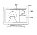
- 3 shows the in-meeting screen 602 before switching the communication PF
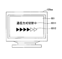
- FIG. 4 shows an example of the switching screen 601 while the communication PF is switched
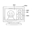
- FIG. 5 shows the in-meeting screen 602 after switching the communication PF. It shows each.
- the screen displayed on the display 120ab is the same.
- an image of the other base (for example, the transmission terminal 10 ab) is displayed in the area 6021, and an image of the second other base (for example, the transmission terminal 10 ac) is displayed in the area 6022.
- an image of the own base is displayed in 6023.
- the communication PF used in the present embodiment will be described.
- the communication PF refers to an infrastructure system or mechanism for communication obtained by combining one or more of a call control method, a communication path, and a video and audio compression method.
- a communication PF in which the transmission terminals 10 communicate with each other using call control using an API called WebRTC is used.
- the transmission terminals 10 aa, 10 ab, and 10 ac are H.264.
- a communication PF is used which is connected by the communication standard 323 (including call control) and communicates via the relay device 30. Therefore, in the above example, the call control and the communication path are switched.
- -Call control (1) H.323 (above), (2) WebRTC (above), (3) SIP (Session Initiation Protocol), (4) Protocol that is an extension of SIP, (5) Protocol of instant messenger, ((5) 6) A protocol using the MESSAGE method of SIP, (7) A protocol of Internet relay chat (IRC (Internet Relay Chat)), and (8) a protocol which is an extension of the protocol of instant messenger.
- Communication path presence or absence of the relay device 30, switching of the relay device 30, switching of functions (interfaces) in the same relay device 30, and the like.
- the video compression method and the audio compression method may be switched independently, or the video compression method and the audio compression method may be switched as a set.
- call control and switching of the communication path involve switching between the video compression method and the audio compression method, they are switched by a set.
- call control or switching of the communication path does not involve switching between the video compression method and the audio compression method, it is not necessary to switch either the video compression method or the audio compression method, and / or either one may be switched.
- FIG. 6 is a schematic view of an example of the transmission system 1 according to the present embodiment.
- the transmission system 1 is a communication system for mutually transmitting information, emotions and the like between a plurality of transmission terminals via the transmission management system 50.
- Examples of the transmission system 1 include a video conference system, a video telephone system, a voice conference system, a voice telephone system, a PC (Personal Computer) screen sharing system, a text chat system, and the like.
- the transmission system 1 further includes a data providing system for transmitting content data in one direction from one transmission terminal to the other transmission terminal via the transmission management system 50.
- the transmission system 1 shown in FIG. 6 includes a plurality of transmission terminals (10aa, 10ab,%), A plurality of mobile terminals (20aa, 20ab,%), And transmission terminals (10aa, 10ab,. .) Are constructed by the display (120aa, 120ab,%), The plurality of relay devices (30a, 30b,%), The transmission management system 50, and the program providing system 90.
- the plurality of transmission terminals 10 transmit and receive image data and audio data as an example of content data. That is, the plurality of transmission terminals 10 are video conference terminals that can use a video conference service. In this embodiment, the transmission terminal 10 is a terminal dedicated to a video conference.
- the plurality of portable terminals 20 transmit and receive image data and audio data as an example of content data.
- the portable terminal 20 may be capable of transmitting and receiving text data. That is, the plurality of mobile terminals 20 may use not only the video conference but also the text chat.
- the mobile terminal 20 is a tablet type terminal, a mobile phone, a smart phone, a PDA (Personal Digital Assistant), a wearable PC, a game machine, a general-purpose PC terminal, a car navigation terminal, an electronic white board, a projector, unless otherwise specified.
- a general-purpose portable terminal such as a projection device.
- the mobile terminal 20 is wirelessly connected to the communication network 2 via, for example, a mobile phone communication network or WiFi (Wireless Fidelity).
- the transmission terminal 10 and the portable terminal 20 are referred to as an information processing apparatus.
- the transmission terminal 10 and the portable terminal 20 are managed by a transmission management system 50 that manages call control of the transmission system 1.
- an arbitrary transmission terminal among the plurality of transmission terminals (10aa, 10ab,...) Is expressed as “transmission terminal 10”, and among the plurality of mobile terminals (20aa, 20ab,.
- the arbitrary portable terminal of is represented as "portable terminal 20". The same applies to the display 120, the relay device 30, and the router 70.
- a terminal that requests the start of a video conference from one transmission terminal 10 or portable terminal 20 to the other transmission terminal 10 or portable terminal 20 is represented as a "request source terminal", and the terminal as the request destination is "destination”. It is expressed as "destination terminal”.
- a management information session for transmitting and receiving various management information is established between the request source terminal and the destination terminal via the transmission management system 50.
- a session for transmitting and receiving content data is established between the request source terminal and the destination terminal via the relay device 30.
- the content data session does not necessarily have to go through the relay device 30, and communication may be performed via the transmission management system 50, or the request source terminal and the destination terminal may directly communicate.
- the relay device 30 relays content data between the plurality of transmission terminals 10 and the portable terminal 20 as described above.
- the transmission management system 50 performs login authentication of the transmission terminal 10 and the portable terminal 20, management of the call status, management of the destination list, notification of the transmission destination of content data to the relay device 30, management of the call status, etc. Do.
- the program providing system 90 stores a terminal program for causing the transmission terminal 10 and the portable terminal 20 to realize various functions in an HD (Hard Disk) 304 described later, and the program for the terminal in the transmission terminal 10 and the portable terminal 20 The program can be sent.
- the program providing system 90 also stores a transmission management program for causing the transmission management system 50 to realize various functions in the HD 304, and can transmit the transmission management program to the transmission management system 50.
- the transmission terminals (10aa, 10ab, 10ac,...), The relay device 30a, and the router 70a are communicably connected by the LAN 2a.
- the transmission terminals (10ba, 10bb, 10bc, ...), the portable terminals (20aa, 20ab, ...), the relay device 30b, and the router 70b are communicably connected by the LAN 2b.
- the LAN 2a and the LAN 2b are communicably connected by a dedicated line 2ab including a router 70ab, and are constructed in a predetermined area A.
- the region A is Japan
- the LAN 2a is built in an office in Tokyo
- the LAN 2b is built in an office in Osaka.
- mobile terminals (20aa, 20ab, ...) are used in the area A.
- the transmission terminals (10ca, 10cb, 10cc,...), The relay device 30c, and the router 70c are communicably connected by the LAN 2c.
- the transmission terminals (10da, 10db, 10dc, ...), the mobile terminals (20ac, 20ad, ...), the relay device 30d, and the router 70d are communicably connected by the LAN 2d.
- the LAN 2 c and the LAN 2 d are communicably connected by a dedicated line 2 cd including a router 70 cd and are constructed in a predetermined area B.
- Region B is the United States
- LAN2c is built in a New York office
- LAN2d is Washington D.W. C. It is built in the office of
- mobile terminals (20ac, 20ad, ...) are used in the area B.
- the transmission management system 50 and the program providing system 90 are communicably connected to the transmission terminal 10, the portable terminal 20, and the relay device 30 via the Internet 2i.
- the transmission management system 50 or the program providing system 90 may be installed in the area A or the area B, or may be installed in areas other than these.
- each transmission terminal 10 each mobile terminal 20, each relay device 30, transmission management system 50, each router 70, and program providing system 90 are general IP address in simple IPv4 is shown.
- FIG. 7 is an example of a hardware configuration diagram of the transmission terminal according to the present embodiment.
- the transmission terminal 10 of the present embodiment has a central processing unit (CPU) 101 that controls the overall operation of the transmission terminal 10.
- CPU central processing unit
- a ROM (Read Only Memory) 102 storing a program used to drive the CPU 101 such as an IPL (Initial Program Loader) and a RAM (Random Access Memory) 103 used as a work area of the CPU 101 are also included.
- IPL Initial Program Loader
- RAM Random Access Memory
- the flash memory 104 further includes a flash memory 104 for storing various data such as image data and audio data, and a solid state drive (SSD) 105 for controlling reading or writing of various data to the flash memory 104 under the control of the CPU 101.
- a media drive 107 controls reading or writing (storage) of data to a recording medium 106 such as a flash memory, and an operation button 108 operated when selecting a destination of the transmission terminal 10 or the like.
- a power switch 109 for switching on / off the power of the transmission terminal 10 and a network I / F (Interface) 111 for data transmission using the communication network 2 are provided.
- the transmission terminal 10 also has a built-in camera 112 that captures an object and obtains image data according to the control of the CPU 101, an imaging element I / F 113 that controls driving of the camera 112, and a built-in microphone that inputs voice. Having 114. Further, it has a built-in speaker 115 for outputting sound, and an audio input / output I / F 116 for processing input / output of an audio signal between the microphone 114 and the speaker 115 under the control of the CPU 101.
- the display I / F 117 transmits image data to the external display 120 according to control of the CPU 101, an external device connection I / F 118 for connecting various external devices, and an authentication acceptance I / F 119. Further, as shown in FIG. 7, a bus line 110 such as an address bus or a data bus is provided to electrically connect the above-described components.
- the display 120 is a display unit configured of a liquid crystal or an organic EL that displays an image of a subject, an operation icon, and the like.
- the display 120 is also connected to the display I / F 117 by a cable 120c.
- the display 120 of the transmission terminal 10 is connected to the display I / F 117 by the cable 120 c, the present invention is not limited thereto.
- the display 120 may be incorporated in the transmission terminal 10.
- An external device such as an external camera, an external microphone, and an external speaker can be connected to the external device connection I / F 118 by a USB (Universal Serial Bus) cable or the like.
- USB Universal Serial Bus
- the authentication acceptance I / F 119 is an interface for receiving input of authentication information from the user, and specifically, corresponds to an IC card reader (for example, NFC (Near field communication), a reader such as an SD card or SIM card). .
- an IC card reader for example, NFC (Near field communication), a reader such as an SD card or SIM card.
- FIG. 8 is an example of a hardware configuration diagram of the transmission management system 50 according to the present embodiment.
- the hardware configuration of the transmission management system 50 etc. shown in the drawings does not have to be housed in one case or provided as a group of devices, and it is preferable that the transmission management system 50 etc. be provided. Indicates a hard element. Also, in order to support cloud computing, the physical configuration of the transmission management system 50 or the like according to the present embodiment may not be fixed, and hardware resources are dynamically connected and disconnected according to the load. May be configured.
- the transmission management system 50 has a CPU 301 that controls the overall operation of the transmission management system 50, a ROM 302 that stores programs used to drive the CPU 301 such as an IPL, and a RAM 303 that is used as a work area of the CPU 301. It also has an HD 304 for storing various data such as a transmission management program, and an HDD (Hard Disk Drive) 305 for controlling reading and writing of various data to the HD 304 under the control of the CPU 301.
- a media drive 307 that controls reading or writing (storage) of data to a recording medium 306 such as a flash memory, and a display 308 that displays various information such as a cursor, a menu, a window, characters, or an image.
- a network I / F 309 for data transmission using the communication network 2 and a keyboard 311 provided with a plurality of keys for inputting characters, numerical values, various instructions and the like.
- a mouse 312 is provided which performs selection and execution of various instructions, selection of a processing target, movement of a cursor, and the like.
- a CD-ROM drive 314 is provided to control reading and writing of various data with respect to a compact disc read only memory (CD-ROM) 313 as an example of a removable recording medium.
- a bus line 310 such as an address bus or a data bus is provided to electrically connect the above-described components.
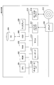
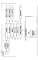
- FIG. 9 is an example of a functional block diagram of the transmission terminal 10 and the transmission management system 50.
- the program providing system 90 is omitted in FIG. 9 because it is not directly related to the present embodiment.
- the portable terminal 20 has almost the same function as the transmission terminal 10, and even if there is a difference, there is no hindrance in realizing the present embodiment.
- the transmission terminal 10 includes a transmission / reception unit 11, a display control unit 12, an imaging unit 13, an audio input unit 14a, an audio output unit 14b, a destination list creation unit 15, an operation input reception unit 16, a login request unit 17, and a switching image determination parameter measurement.
- a unit 18, a switching image determination unit 21, and a storage and readout processing unit 19 are included.
- Each part of the transmission terminal 10 is realized by one of the components shown in FIG. 7 operating according to an instruction from the CPU 101 according to the terminal program 1100 expanded on the RAM 103 from the flash memory 104. Function or means to be functioned.
- the transmission terminal 10 also has a non-volatile storage unit 1000 constructed by the flash memory 104 shown in FIG. 7.
- a non-volatile storage unit 1000 constructed by the flash memory 104 shown in FIG. 7.
- each database built in the non-volatile storage unit 1000 will be described.
- a switching image management DB 1001 configured by a switching image management table as shown in Table 1 is constructed.
- file names are associated with switching image numbers.
- the file name is the name of a file storing the switching image.
- the switching image is an example of a display image.
- the switching image is an image displayed on the switching screen 601 of FIG. 2, FIG. 3 and FIG.
- a video it may include videos with different playing times, promotional videos of musicians, news, advertisements, and the like.
- the creator of the switching image can prepare audio data in addition to the switching image. Therefore, in the case of a moving image, the transmission terminal 10 can reproduce, for example, audio such as “currently switching communication method” while the switching screen 601 is displayed. Further, in the case of a still image, the transmission terminal 10 can reproduce the sound by associating the audio file with the switching image and the switching image number.
- a switching image setting management DB 1002 configured by a switching image setting management table as shown in Table 2 is constructed.
- the switching image setting management table conditions for which switching image of the switching image management table is selected by the switching image determination unit 21 described later are managed.
- a network band communication band
- the number of conference participants, and a switch image number are registered in association with a management number.
- a still image is associated with a large network bandwidth and a small number of conference participants, and a video is associated with a small network bandwidth and a large number of conference participants.
- the switching image determination unit 21 described later has a switching image with a switching image number i_001. Decide to use. Since the switching image number is determined, the switching image determination unit 21 can read the switching image from the switching image management table.
- the network band is listed here because the time required to switch the communication PF is easily changed depending on the network band. Also, as the number of conference participants increases, the time to establish a session tends to be longer. In addition, even if the switching time is long, if it is a moving image, the switching screen displayed by the transmission terminal 10 changes, so that the user can easily understand that it is not a malfunction of the communication or the transmission terminal 10. If the switching time is short, the time during which the still image of the switching screen 601 is displayed is also short, and switching of the communication PF is completed before the user misunderstands whether a problem has occurred (even if the moving image is displayed, It will make you feel uncomfortable instead. Therefore, the transmission terminal 10 can more appropriately notify the user that the communication PF is being switched, by switching the still image or the moving image according to the network band and the number of the conference participants.
- a parameter for determining the switching image the network band and the number of conference participants are listed as an example, but the parameters for determining which switching image is not limited to these.
- a parameter (such as load level of the transmission management system 50) that affects (correlates) the time required to switch the communication PF may be registered in the switching image setting management table.
- the non-volatile storage unit 1000 stores a terminal program 1100.
- the terminal program 1100 is distributed from the program providing system 90 and is also stored in a computer readable recording medium such as the recording medium 106 and distributed as an installable or executable file. It is also good.
- the transmission / reception unit 11 of the transmission terminal 10 is realized by an instruction from the CPU 101 shown in FIG. 7 and the network I / F 111 shown in FIG. 7 and transmits the other transmission terminal 10 via the communication network 2 It transmits and receives various data with the management system 50 and the relay device 30 and the like.
- the transmitter / receiver unit 11 is connected to an ⁇ function unit 11 a and a ⁇ function unit 11 b.
- the function unit for ⁇ 11 a performs processing necessary for the communication PF for ⁇
- the function unit for ⁇ 11 b performs processing necessary for the communication PF for ⁇ .
- the function unit 11a for ⁇ communicates with, for example, the global IP address and port number used in WebRTC
- the function unit 11b for ⁇ is the IP address of the relay apparatus 30 (a global IP address or a private IP address may be used) Communicate to the destination.
- the ⁇ function unit 11a communicates using the communication protocol used for the ⁇ communication PF, and the ⁇ function unit 11b uses the ⁇ for communication PF Communicate with the communication protocol. Furthermore, when the compression method of the video and audio of the communication PF of ⁇ and the communication PF of ⁇ is different, the ⁇ functional unit 11a compresses and expands the video and audio compressed by the compression method used for the communication PF of ⁇ .
- the function unit 11 b for ⁇ compresses / decompresses video and audio compressed by the compression method used for the communication PF of ⁇ .
- the display control unit 12 is realized by an instruction from the CPU 101 shown in FIG. 7 and the display I / F 117 shown in FIG. 7 and transmits (outputs) image data to the external display 120. To control.
- the imaging unit 13 is realized by an instruction from the CPU 101 illustrated in FIG. 7 and the camera 112 and the imaging device I / F 113, captures an image of a subject, and outputs image data obtained by capturing the image.
- the voice input unit 14a is realized by an instruction from the CPU 101 shown in FIG. 7 and the voice input / output I / F 116, and after the user's voice is converted into a voice signal by the microphone 114, the voice related to the voice signal Enter data.
- the audio output unit 14 b is realized by an instruction from the CPU 101 and the audio input / output I / F 116 illustrated in FIG. 7, outputs an audio signal related to audio data to the speaker 115, and causes the speaker 115 to output audio.
- the destination list creation unit 15 is realized by an instruction from the CPU 101 shown in FIG. 7 and receives the destination status information received from the transmission management system 50 (destination candidate terminal and destination candidate transmission terminal 10 and mobile terminal 20 operating status Create and update the destination list on the basis of.
- the operation input receiving unit 16 is realized by an instruction from the CPU 101, the operation button 108, and the power switch 109 shown in FIG. 7, and receives various inputs from the user. For example, when the user turns on the power switch 109 shown in FIG. 7, the operation input receiving unit 16 receives power on and turns on the power.
- the login request unit 17 is realized by an instruction from the CPU 101 shown in FIG. 7 and is a login request information indicating that the transmission management system 50 is requested to log in upon receipt of the power ON, and a request source terminal Automatically send the current IP address of. It may be triggered by the authentication operation of the user. Further, at the time of transmission, the transmission / reception unit 11 transmits via the communication network 2.
- the switching image determination parameter measuring unit 18 measures parameters for the switching image determining unit 21 to select a switching image.
- the parameters are, for example, the network bandwidth and the number of conference participants.
- the switching image determination unit 21 is realized by an instruction from the CPU 101 shown in FIG. 7 and determines the switching image to be displayed on the display 120 of the transmission terminal 10 between the start and the end of switching when the communication PF is switched. Do.
- Storage / read processing unit 19 is realized by an instruction from CPU 101 shown in FIG. 7 and SSD 105 shown in FIG. 7 to store various data in nonvolatile storage unit 1000 or store in nonvolatile storage unit 1000. It performs processing to read out various data.
- the non-volatile storage unit 1000 includes a communication ID (Identification) for identifying the terminal or user of the transmission terminal 10 as a communication destination, type identification information (information indicating the distinction between the transmission terminal 10 and the portable terminal 20), A password or the like is stored.
- the communication ID and the password may not be stored in the non-volatile storage unit 1000, and may be input by the user each time a login request is made to the transmission management system 50, for example.
- the communication ID in the present embodiment indicates identification information such as a language, characters, symbols, or various marks used to uniquely identify a transmission terminal or a user who uses the transmission terminal.
- the communication ID and the relay device ID may be identification information in which at least two of the language, characters, symbols, and various marks are combined.
- the transmission management system 50 includes a transmission / reception unit 51, a PF switching determination unit 52, an authentication unit 53, a session management unit 54, a communication status detection unit 55, and a storage / read processing unit 59. These units are functions or means implemented by any of the components shown in FIG. 8 being operated by an instruction from the CPU 301 according to the development from the HD 304 onto the RAM 303. .
- the transmission management system 50 has a non-volatile storage unit 5000 in which storage of various data (or information) is maintained even when the power of the transmission management system 50 is turned off.
- This non-volatile storage unit 5000 It is constructed by the HD 304 shown in FIG.
- a session management DB 5001 configured of a session management table as shown in Table 3 is constructed.
- this session management table for each session ID used to execute a session for selecting the relay device 30, communication PF, relay device ID of the relay device 30 used for relaying data, communication ID of the request source terminal, The communication ID of the destination terminal and the conference ID are associated and managed. When the relay device 30 is not used, nothing is registered in the relay device ID.
- a destination list management DB 5002 constructed of a destination list management table for managing destination information as shown in Table 4 is constructed.
- the communication IDs of the transmission terminals 10 or the portable terminals 20 of all the destination candidates are managed in association with the communication ID of the request source terminal that requests the start (calling) of the connection in the video conference.
- the communication ID of the destination candidate is the transmission terminal 10 or the portable terminal 20 with which the request source terminal can start communication.
- a terminal management DB 5003 configured of a terminal management table as shown in Table 5 is constructed.
- the operation state of each transmission terminal, the name when each communication ID is a destination, and the IP address of the terminal are associated and managed for each communication ID of the transmission terminal 10.
- an authentication management DB 5004 configured with an authentication management table as shown in Table 6 is constructed.
- the password of each transmission terminal 10 or user is associated and managed for each communication ID of the transmission terminal 10 or user.
- a PF determination management DB 5005 configured by a PF determination table as shown in Table 7 is constructed.
- communication PFs are associated and managed according to the number of bases.
- the communication PF of ⁇ means communication using WebRTC
- the communication PF of ⁇ means communication via the relay device 30 (communication using H.323 as call control).
- a transmission management program 5100 is stored.
- the transmission management program 5100 is distributed from the program providing system 90.
- a file in an installable format or an executable format may be recorded and distributed in a computer readable recording medium such as the recording medium 306 or the CD-ROM 313.
- ⁇ Functional Configuration of Transmission Management System >> Next, each functional configuration of the transmission management system 50 will be described in detail.
- the transmission / reception unit 51 is realized by an instruction from the CPU 301 shown in FIG. 8 and the network I / F 309 shown in FIG. 8 and transmits various data (the transmission terminal 10 and the relay device 30 via the communication network 2). Or send and receive information).
- Authentication unit 53 is realized by an instruction or the like from CPU 301 shown in FIG.
- the authentication unit 53 determines whether the combination of the communication ID and the password included in the login request information received via the transmission and reception unit 51 matches the one registered in the authentication management DB 5004 or not. Or authenticate the user.
- the authentication method is not limited to this, and a client certificate (an authentication method using a public key and a secret key) may be used.
- the session management unit 54 is realized by an instruction from the CPU 301 shown in FIG.
- the session management unit 54 relays the communication PF and content data to the session management DB 5001 when a connection with the destination terminal is requested from the transmission terminal 10 for which authentication has been established by the authentication unit 53 (when start request information is acquired).
- the relay device ID of the relay device 30 (when the relay device 30 relays), the session ID, the communication ID of the request source terminal, the communication ID of the destination terminal, and the conference ID are stored in association with one another and managed.
- the session management unit 54 establishes an appropriate session for each communication PF, the details of which will be described later.
- the communication status detection unit 55 is realized by an instruction from the CPU 301 shown in FIG. 8 and detects the communication status between the transmission terminals 10 and between the transmission terminal 10 and the transmission management system 50.
- the network bandwidth and the number of bases can be raised.
- the PF switching determination unit 52 is realized by an instruction from the CPU 301 shown in FIG. 8 and selects (determines) an appropriate communication PF with reference to the PF determination table according to the communication status. Details of the determination of the communication PF and the determination of switching will be described later. If it is determined that the communication PF is to be switched, the session management unit 54 is notified of the communication PF after switching, and the session establishment is requested.
- Storage / read processing unit 59 is realized by an instruction from CPU 301 shown in FIG. 8 and HDD 305 shown in FIG. 8, stores various data in nonvolatile storage unit 5000, and nonvolatile storage unit A process of reading out various data stored in 5000 is performed.
- ⁇ About establishment of session according to communication PF >> First, establishment of a WebRTC session used in the communication PF of ⁇ will be briefly described. In WebRTC, for example, browsers (or applications having functions equivalent to this) communicate with each other without passing through a server.
- the transmission management system 50 uses the fact that the operation state of the transmission terminal 10 is managed in the terminal management table, and the other user is addressed to the other Allows to identify the user of.
- the destination user can be specified by a destination list screen described later.
- the session management unit 54 functions as a STUN server.
- the transmission terminals 10aa and 10ab are notified of the global IP address and port number outside the NAT (Network Address Translation) apparatus of the in-house network or the home network in which the transmission terminal 10 on the opposite side is arranged. Since the transmission terminals 10aa and 10ab know the other party's global IP address and port number, one-to-one communication becomes possible beyond the NAT device.
- NAT Network Address Translation
- the session management unit 54 selects an appropriate relay device 30.
- various methods can be considered as how to select the relay apparatus 30, the delay time of the transmission from the relay apparatus 30 to the transmission terminal 10 etc. are considered in a present Example.
- the session management unit 54 When determining the relay device 30, the session management unit 54 notifies the relay device 30 of the communication IDs of the transmission terminals 10aa and 10ab communicating in one video conference.
- the session management unit 54 or the relay device 30 numbers the session ID and assigns the conference ID as participating in the same conference.
- the session management unit 54 also notifies the transmission terminals 10aa and 10ab of the IP address of the relay apparatus 30.
- the relay device 30 relays the content data to the transmission terminals 10aa and 10ab participating in the same video conference based on the communication ID.
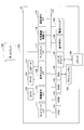
- FIG. 10 is an example of a sequence diagram showing a procedure in which the transmission terminals 10aa and 10ab establish a session.
- the communication PF of ⁇ is used.
- the video conference may be started by the communication PF designated by the user in order for the transmission system 1 to cope with the case where the video conference is scheduled to be performed by three or more users.
- the user can start a video conference on the communication PF of ⁇ by specifying the communication PF of ⁇ as the transmission management system 50.
- S1 When the user turns on the power switch 109, the operation input receiving unit 16 receives power on and turns on the power.
- the login request unit 17 automatically sends login request information indicating a login request to the transmission management system 50 from the transmission / reception unit 11 via the communication network 2 when the power is turned on.
- the login request can be transmitted at any timing by user operation as well as when the power is turned on.
- the login request information includes a communication ID for identifying the transmission terminal 10aa that is the request source, and a password.
- the transmission management system 50 on the receiving side can grasp the IP address (global IP address) of the transmission terminal 10aa.
- S3 The authentication unit 53 of the transmission management system 50 determines whether the same communication ID and password as the communication ID and password contained in the login request information received via the transmission / reception unit 51 are managed in the authentication management table. Perform terminal authentication by doing this.
- S4 When the authentication of the transmission terminal 10aa is established by the authentication unit 53, the session management unit 54 reads the communication ID of the destination terminal that the transmission terminal 10aa takes as a destination candidate from the destination management table, and the operation status of the destination terminal is the terminal management table. Read from In this process, it is assumed that the transmission terminal 10ab which is the destination terminal is online.
- the transmission / reception unit 51 transmits, to the transmission terminal 10aa via the communication network 2, the destination state information including the communication ID and the operation state of each transmission terminal of the destination candidate.
- the destination state information includes the name registered in the terminal management table.
- the transmission terminal 10aa can grasp the current operation state of the transmission terminal 10ab of the destination list that can communicate with the transmission terminal 10aa.
- the transmitting and receiving unit 51 transmits the communication ID of the transmission terminal 10aa that has made the login request and the operation state thereof to the transmission terminal (here, the transmission terminal 10ab) that includes the transmission terminal 10aa in the destination list.
- the transmission terminals 10 of the destination candidate registered in the destination list can mutually grasp the operation state of the other party.
- the destination list creation unit 15 of the transmission terminal 10aa creates a destination list and causes the display 120 to display the destination list.
- the user of the transmission terminal 10aa can select a communication ID for requesting start of communication from the destination list screen. In the present embodiment, it is assumed that the transmission terminal 10ab is selected.
- the start request information includes a request source communication ID and a destination communication ID. Further, as a result, the transmission / reception unit 51 of the transmission management system 50 recognizes the IP address of the request source terminal 10aa.
- S9 The session management unit 54 of the transmission management system 50 performs processing for establishing a session. That is, the session ID, the communication PF, the request source communication ID, the destination communication ID, and the conference ID are registered in the session management table. Further, the operation status is set to "in communication" in association with the transmission terminals 10aa and 10ab in the terminal management table.
- S10, S11 The session management unit 54 of the transmission management system 50 notifies the transmission terminals 10aa and 10ab of the other party's global IP address and port number, respectively, for the NUT crossing described above.
- S12 With this, the transmission terminals 10aa and 10ab can start communication with the communication PF of ⁇ .
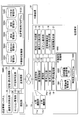
- FIG. 11 is an example of a sequence diagram showing a switching procedure of the communication PF.
- the transmission terminals 10aa and 10ab communicate by the communication PF of ⁇ , and the in-meeting screen 602 is displayed.
- the transmission terminal 10 ac transmits, to the transmission management system 50, start request information in which the transmission terminal 10 aa is the destination terminal.
- the transmission terminal 10aa may invite the transmission terminal 10ac to a video conference by notifying the session ID.
- the transmission / reception unit 11 of the transmission terminal 10ac transmits start request information to the transmission management system 50.
- the start request information includes a request source communication ID and a destination communication ID. Further, as a result, the transmission / reception unit 51 of the transmission management system 50 recognizes the IP address of the request source terminal 10ac.
- the transmission terminal 10ab that has already been teleconferenceed with the transmission terminal 10aa is counted based on the meeting ID of the session management table. Therefore, the number of bases will increase to three.
- the PF determination table when the number of bases is 3 or more, it is determined that the communication PF is switched to ⁇ .
- the communication PF is switched before the transmission terminal 10ac communicates with the communication PF of ⁇ , but the communication PF may be switched after the transmission terminal 10ac participates in a video conference by the communication PF of ⁇ . .
- S4, S5 The PF switching determination unit 52 transmits a switching start notification to the transmission terminals 10aa and 10ab via the transmission / reception unit 51.
- S6, S7 The transmission terminals 10aa, 10ab end the display of the in-meeting screen 602 and perform processing to display the switching screen 601. This process will be described later.
- S8 Next, the session management unit 54 updates the session management table. Table 6 shows the updated session management table.
- the communication PF is changed from ⁇ to ⁇ , and the relay device 30 required for the communication PF of ⁇ is determined and registered in the relay device ID.
- the session ID in the session of the transmission terminals 10aa and 10ac, the communication PF, the relay device ID, the request source communication ID, the destination communication ID, and the conference ID are registered.
- a new session ID or the like may be created.
- a session management table in a format suitable for each communication PF may be prepared, and a session ID or the like may be registered in a session management table in a format corresponding to the switched communication PF.
- the session management unit 54 requests the relay device 30 to start relaying together with the communication IDs of the transmission terminals 10aa, 10ab and 10ac.
- the relay device 30 participates in one video conference of the transmission terminals 10aa, 10ab, and 10ac, and can relay content data transmitted from the transmission terminal 10aa to the transmission terminals 10ab and 10ac, for example.
- S10, 11 The PF switching determination unit 52 of the transmission management system 50 sends a communication platform switching instruction to the transmission terminals 10aa and 10ab. As a result, the communication PF after switching is notified to the transmission terminal 10aa and the transmission terminal 10ab.
- S12, 13 The PF switching determination unit 52 of the transmission management system 50 notifies the transmission terminals 10aa and 10ab of the IP address of the relay device 30. Thus, the transmission terminal 10aa and the transmission terminal 10ab can transmit content data to the relay device 30.
- S14, 15 The transmission terminal 10aa switches the communication PF, and the transmission terminal 10ab switches the communication PF. That is, the transmission terminals 10aa and 10ab switch the communication by the transmission / reception unit 11 and the function unit 11a for ⁇ to the communication by the transmission / reception unit 11 and the function unit 11b for ⁇ .
- S16 As described above, a session is established in which the transmission terminal 10aa and the transmission terminal 10ab can transmit and receive content data through the relay device 30.
- the relay device 30 (which may be the transmission terminal 10 aa or the transmission terminal 10 ab) notifies the transmission management system 50 of the session establishment, so that the transmission management system 50 can determine that it may switch to the in-meeting screen 602.
- the PF switching determination unit 52 of the transmission management system 50 notifies the transmission terminals 10aa and 10ab of the switching end notification. Accordingly, the transmission terminals 10aa and 10ab switch from the switching screen 601 to the in-conference screen 602.
- S19 Next, the PF switching determination unit 52 of the transmission management system 50 notifies the transmission terminal 10ac of the IP address of the relay device 30 and the communication PF.
- the transmission terminal 10 ac can transmit content data to the relay device 30 using the transmission / reception unit 11 and the function unit 11 b for ⁇ .
- S20 As described above, a session in which the transmission terminal 10aa and the transmission terminal 10ac can transmit and receive content data through the relay device 30 has been established.
- the transmission management system 50 may detect the end of the switching of the communication PF.
- the transmission terminals 10aa and 10ab can detect the end of the switching of the communication PF by enabling communication via the relay device 30.
- the timing of switching from the in-conference screen 602 to the switching screen 601 and the timing of switching from the switching screen 601 to the in-conference screen 602 are merely an example.
- FIG. 11 from the transmission terminal 10 in which the communication PF has been switched, the display of the switch image is stopped and the in-conference image is displayed again. That is, the timing at which the in-meeting image is redisplayed differs for each transmission terminal 10. In this method, the time during which each transmission terminal 10 is displaying the switching image can be shortened.
- the switching end notification may be transmitted to each of the transmission terminals 10.
- the time during which each transmission terminal 10 is displaying the switching screen 601 may be long, but all the transmission terminals 10 switch from the switching screen 601 to the in-conference screen 602 almost simultaneously. You can start a video conference at once.
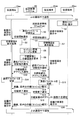
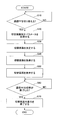
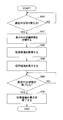
- FIG. 12 is an example of a flowchart diagram showing a procedure of processing of causing the transmission terminal 10 to end the display of the in-meeting screen 602 and display the switching screen 601. The process of FIG. 12 is executed while the in-meeting screen 602 is displayed.
- the switching image determination unit 21 determines whether to switch the communication PF (S10). That is, it is determined whether or not the switching start notification has been transmitted from the transmission management system 50. If the switching start notification is not transmitted, the transmission terminal 10 does nothing.
- the switching image determination parameter measuring unit 18 of the transmission terminal 10 measures a parameter for selecting a switching image (S20).
- the switching image determination parameter measurement unit 18 measures the network bandwidth by transmitting data for measurement of the parameters to the transmission management system 50 or the like.
- the communication PF is WebRTC (P2P)
- the number of conference participation sites is known to the transmission terminal 10 because the number of the transmission terminals 10 transmits the image and the voice (the transmission terminal 10).
- the transmission management system 50 may be inquired about the number of transmission terminals 10 of the same conference ID as that of the user.
- the transmission terminal 10 may superimpose on the in-meeting screen 602 and display a message such as “I will switch the communication platform from now on” on the display 120 when the switching start notification is transmitted. As a result, it is possible to provide a notification period until the in-meeting screen 602 is switched to the switching screen 601.
- the switching image determination unit 21 of the transmission terminal 10 refers to the switching image setting management table based on, for example, the network band and the number of conference participants, and determines the switching image number (S30).
- the switching image determination unit 21 of the transmission terminal 10 reads the file of the switching image number determined in step S30 from the switching image management table (S40).
- the display control unit 12 of the transmission terminal 10 displays the switching screen 601 as shown in FIG. 13, FIG. 14, and FIG. 15 on the display 120 (S50). This makes it possible to display the switching screen 601 appropriate for the network band and the number of conference participants.
- the switching image determination unit 21 of the transmission terminal 10 determines whether the switching of the communication PF is completed (S60). That is, it is determined whether a switching end notification has been obtained from the transmission management system 50 or whether a session with the transmission terminal 10 of the other party via the relay device 30 has been established.
- the display control unit 12 ends the display of the switching screen 601 and resumes the display of the in-meeting screen 602 (S70).
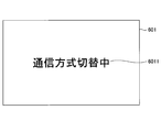
- FIG. 13 is a diagram showing an example of the switching image.
- This switching image may be referred to as a switching screen 601.
- the switching image in FIG. 13 (which may be referred to as a switching screen 601) is a scene with a moving image.
- This switching image has a message 6011 "in switching communication mode", and an icon 6012 indicating that the switching is in progress.
- the colored portion of the icon 6012 changes with time.
- Such a moving image switching image may be created sufficiently longer than the time required to switch the communication PF, or during switching of the communication PF, the display control unit 12 repeatedly reproduces the same switching image. It is also good.
- six still images with different colored parts of the icon 6012 may be prepared (the number is equal to the number of triangles of the icon), and the display control unit 12 may switch with time and display on the display 120 .
- FIG. 14 is an example of a switching image displayed when the time required for switching is short
- FIG. 15 is an example of a switching image displayed when the time required for switching is long. If the time required for switching is long, the amount of information can be increased to reduce the user's feeling that the switching time is long. Also, much information can be given to the user as in the URL 6019 of FIG.
- the switching screen 601 is displayed on the display 120 while the transmission system 1 of the present embodiment switches the communication PF during the video conference, the user grasps what state the transmission system 1 is in. It can be easy to do. For example, when the switching time is long, it is possible to display a long moving image, and when the switching time is long, it is also possible to stream news and promotional videos. Also, an advertisement may be displayed for free users to allow the service provider to collect the charge of the transmission system 1. ⁇ Modification>
- the switching image is not related to the still image or the moving image. If only one is provided, no measurement of the parameters is necessary.
- FIG. 16 is an example of a flowchart showing an example of a process of causing the transmission terminal 10 to end the display of the in-meeting screen 602 and display the switching screen 601.
- step S20 in which the switching image determination parameter measuring unit 18 measures a parameter
- step S30 in which the switching image determining unit 21 determines a switching image.
- step S20 in which the switching image determination parameter measuring unit 18 measures a parameter
- step S30 in which the switching image determining unit 21 determines a switching image.
- there is only one switching image there is no problem in switching to the switching image.
- the transmission terminal 10 which determines the switching image based on the time required to switch the communication PF will be described.
- FIG. 17 is an example of a functional block diagram of the transmission terminal 10 in the present embodiment.
- the transmission management system 50 is omitted because it is the same as FIG. 9 of the first embodiment.
- the components given the same reference numerals in FIG. 9 perform the same functions, and therefore, only main components of the present embodiment may be mainly described.
- a switching image setting management DB 1002 (an example of a switching time storage unit) configured by a switching image setting management table as shown in Table 9 is constructed.
- the function of the switching image setting management table of Table 9 is the same as that of the switching image setting management table of Table 2.
- switching times and switching image numbers are registered in association with management numbers.
- switching image setting management table switching image numbers are managed in association with the time (switching time) taken to switch the communication PF. Therefore, the switching image determination unit 21 of the present embodiment can determine the switching image based on the switching time of the communication PF (the measured past switching time).
- a switching history management DB 1003 configured of a switching history management table as shown in Table 10 is constructed.
- the switching time is managed in association with the switching date and time when the communication PF was switched.
- the switching date and time may not be necessary, but the switching date and time can be referred to, for example, the switching time of the past one week, the same day of the past, and the same time zone, by recording the switching date and time.
- the transmission terminal 10 of the present embodiment has a switching history processing unit 22.
- the switching history processing unit 22 is realized by an instruction from the CPU 101 shown in FIG. 7 and stores the switching time required for switching the communication PF in the switching history management DB 1003 in association with the switching date and time.
- the switching time is, for example, the time from the switching start notification in step S4 of the sequence diagram of FIG. 11 to the switching end notification in step S18, or the switching start notification in step S4 of the sequence diagram of FIG.
- the transmission terminal 10 may acquire the switching time measured by the transmission management system 50 and register the switching time in the switching history management DB 1003.
- the switching image determination unit 21 (an example of the switching time estimation unit) of the present embodiment estimates the switching time of the communication PF based on the switching time stored in the switching history management table.
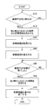
- FIG. 18 is an example of a flowchart showing an example of a process of causing the transmission terminal 10 to end the display of the in-meeting screen 602 and display the switching screen 601.
- the switching image determination unit 21 determines whether to switch the communication PF (S10). That is, it is determined whether or not the switching start notification has been transmitted from the transmission management system 50. If the switching start notification is not transmitted, the transmission terminal 10 does nothing.
- the switching image determination unit 21 determines the switching image with reference to the switching history management table and the switching image setting management table (S15).
- measurement of the switching time is started.
- the trigger for starting the measurement of the switching time is not limited to this.
- the switching image determination unit 21 reads from the switching image setting management table the switching image number associated with the switching time estimated with reference to the switching history management table. For example, when the switching time estimated with reference to the switching history management table is 6s, i_003 is read as the switching image number.
- step S40 The subsequent processes from step S40 to step S60 are the same as in FIG.
- step S70 is the same as that of FIG.
- the transmission terminal 10 can use the optimum switching image in consideration of the actual time taken to switch the communication PF.
- the switching image setting management tables of the first embodiment and the present embodiment may be used in combination.
- Table 11 shows another example of the switching image setting management table.
- the function of the switching image setting management table of Table 11 is the same as that of the switching image setting management table of Table 2.
- the network band, the number of conference participants, the switching time, and the switching image number are registered in association with the management number.
- the switching image determination unit 21 performs switching, which is estimated from the switching history management table, of the switching time associated with the network bandwidth at the time of switching communication PF and the number of conference participants. It is possible to read out the switching image number adapted to the time. Since the switching image number associated with the estimated switching time out of the switching time associated with at least the same network band and the number of conference participants as at the present time is obtained, it becomes easier to select a more appropriate switching image.
- the network band and the number of conference participants may be registered in the switching history management table.
- Table 12 shows another example of the switching history management table.
- the switching history management table of Table 12 the network band, the number of conference participants, and the switching time are registered in association with the switching date and time. Therefore, if such a switching history management table is used, the switching image determination unit 21 can read out the switching time associated with the network band at the time of switching of the communication PF and the number of conference participants. Then, from the switching image setting management table as shown in Table 9, the switching image number associated with the switching time is read out.
- the switching image determination unit 21 It can improve. Therefore, it becomes easy to select an appropriate switching image.
- FIG. 19 is an example of a functional block diagram of the transmission terminal 10 in the present embodiment.
- the transmission management system 50 is omitted because it is the same as FIG. 9 of the first embodiment.
- the components given the same reference numerals in FIG. 9 perform the same functions, and therefore, only main components of the present embodiment may be mainly described.
- the switching image setting management DB 1002 is not constructed in the non-volatile storage unit 1000 of this embodiment. Further, the switching image management DB 1001 of the present embodiment stores the image of the in-meeting screen 602 displayed on the display 120 during the meeting. For example, it is an image of the in-meeting screen 602 displayed on the display immediately before switching of the communication PF. Thereby, the transmission terminal 10 can display the image immediately before the switching of the communication PF is started during the switching of the communication PF.
- the transmission terminal 10 of the present embodiment has an image acquisition unit 23.
- the image acquisition unit 23 is realized by an instruction from the CPU 101 shown in FIG. 7, and captures (captures) an image displayed on the display 120.
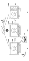
- FIG. 20 is an example of a diagram schematically illustrating the capture of the in-meeting screen 602 displayed on the display 120 and the display of the switching screen 601.
- A) of FIG. 20 shows the in-meeting screen 602 displayed on the display 120aa before the start of switching of the communication PF
- (b) of FIG. 20 shows the switching screen 601 displayed on the display 120aa after the start of switching of the communication PF
- FIG. 20C shows the in-meeting screen 602 displayed on the display 120aa after the switching of the communication PF is completed.
- the transmission terminal 10aa displays the image transmitted from the transmission terminal 10ab on the display 120aa.
- the image acquisition unit 23 of the transmission terminal 10aa takes in the in-conference screen 602 displayed on the display 120aa, and stores the image of the in-conference screen 602 in the switched image management DB 1001.
- the transmission terminal 10aa reads the image of the in-conference screen 602 fetched from the switching image management DB 1001 and displays it on the display 120aa. Further, as shown in (b) of FIG. 20, while the communication PF is being switched, the transmission terminal 10aa reads out the captured image from the switching image management DB 1001 and displays it on the display 120aa. Also, as shown in (c) of FIG. 20, when the switching of the communication PF is completed, the transmission terminal 10aa transmits the in-conference screen 602 including the image transmitted from the transmission terminal 10ab, the other transmission terminal 10ac, etc. to the display 120aa. indicate.
- FIG. 16 is an example of a flowchart showing an example of a process of causing the transmission terminal 10 to end the display of the in-meeting screen 602 and display the switching screen 601.
- the switching image determination unit 21 determines whether to switch the communication PF (S10). That is, it is determined whether or not the switching start notification has been transmitted from the transmission management system 50. If the switching start notification is not transmitted, the transmission terminal 10 does nothing.
- the image acquiring unit 23 loads the in-meeting screen 602 displayed on the display 120 and stores the image of the in-meeting screen 602 in the switching image management DB 1001 as a switching image. (S17).
- the display control unit 12 reads the image captured in step S20 from the switching image management DB 1001 (S40).
- the subsequent processing from step S50 to step S70 is the same as that of FIG.
- the transmission terminal 10 of the present embodiment it is possible to display the switching screen 601 which makes it difficult for the user to notice switching of the communication PF. Moreover, there is no need to prepare a switching image in advance.
- the image acquisition unit 23 may capture a plurality of still images. For example, the image acquisition unit 23 detects that the display content of the screen has largely changed (e.g., when the number of participating bases has changed, when switching from a person to an image of a document, etc.), and captures an image each time. The image acquisition unit 23 may periodically capture a still image.
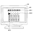
- FIGS. 22, 23 and 24 are diagrams showing an example of the switching screen 601 displayed on the display 120.
- Each of FIGS. 22, 23, and 24 is a switching screen 601.
- the display control unit 12 displays still images stored in the switching image management DB 1001 as the switching screen 601, for example, every several seconds while switching the communication PF.
- the user can refute the contents of the meeting, and can effectively utilize the switching time of the communication PF.
- the image of the on-meeting screen 602 captured by the image acquisition unit 23 does not have to be a still image, and may be a moving image.
- the newest image during the meeting during the latest 10 to 20 seconds is always stored, and this moving image is displayed while switching the communication PF.
- the user can at least know that the transmission terminal 10 has no problem.
- the transmission terminal 10 for displaying the switching phase of the communication PF on the switching screen 601 will be described.
- the switching image setting management DB 1002 of the present embodiment stores conditions for selecting a switching image in accordance with the switching phase of the communication PF.
- Table 13 is an example of the switching image setting management table of this embodiment.
- the switching phase and the switching image number are registered in association with the management number.
- the switching image determination unit 21 can read out the switching image number according to the switching phase.
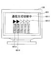
- FIG. 25 and 26 show an example of the switching screen 601.
- FIG. 25 In the switching screen 601 of FIGS. 25 and 26, phases 1 to 5 are displayed under the icon 6012 indicating that the switching is in progress.
- the indicator 6013 of Phase 1 is highlighted with the colored portion being one icon 6012.
- the colored portions are highlighted with two icons 6012 and the markings 6014 of Phase 1 and Phase 2 are highlighted. According to such a switching screen 601, the user can easily grasp how much of all phases of the switching process of the communication PF is in progress.
- the switching image determination unit 21 of this embodiment acquires information on the switching phase of the communication PF from the transmission management system 50 (an example of an acquisition unit).
- phase 1 is a stage at which switching start notification to all terminals is completed
- phase 2 is a stage at which the transmission management system 50 is ready for switching
- phase 3 is a stage at which the relay apparatus 30 is determined
- phase 4 is all transmission terminals
- a phase 5 is a phase where a session is established between all transmission terminals, and the like.
- the switching image determination unit 21 determines the switching image by referring to the switching image setting management table according to the information on the switching phase acquired from the transmission management system 50.
- the signs 6013 and 6014 of phase 1 to phase 5 of the switching image in FIGS. 25 and 26 may be the letters of phase 1 to phase 5 as they are, but they correspond to the switching process performed by the transmission management system 50. Is preferred.
- the appropriate label is described in advance in the switch image by the creator of the switch image. This makes it easy for the user to grasp what stage of switching of the communication PF is.
- the number of transmission terminals 10 for which a session has been established may be used as the switching phase.
- the transmission management system 50 notifies the transmission terminal 10 each time a session is established.
- the switching image determination unit 21 of the transmission terminal 10 determines a switching image according to the number of transmission terminals 10 for which a session has been established. Therefore, on the switching screen 601 in this case, the indication "the first session has been established", the indication "the second session has been established", etc. gradually increase. In addition to these indications, it is preferable to indicate the total number of locations.
- the switching image it is not necessary for the switching image to include the indicators 6013 and 6014 of the phase 1 to the phase 5, and the indicators 6013 and 6014 of the phase 1 to the phase 5 are superimposed and displayed on the switching image of the first to third embodiments. It is also good. That is, the display control unit 12 superimposes and displays the switching phase notified from the transmission management system 50 on the switching screen 601.
- FIG. 9 and the like shown in the above embodiments is divided according to the main functions in order to facilitate understanding of the processing of the transmission terminal 10 and the transmission management system 50.
- the present invention is not limited by the method and name of division of processing units.
- the processing of the transmission terminal 10 and the transmission management system 50 can also be divided into more processing units according to the processing content. Also, one processing unit can be divided to include more processes.
- the transmission terminal 10 has been described as having the switching image management DB 1001, the switching image setting management DB 1002, and the switching history management DB 1003.
- the transmission management system 50 may have one or more of the switching image management DB 1001, the switching image setting management DB 1002, and the switching history management DB 1003.
- the transmission management system 50 transmits, for example, the switching image management DB 1001, the switching image setting management DB 1002, and the switching history management DB 1003 to the transmission terminal 10 that has logged in.
- the transmission management system 50 may determine the switching image.
- the transmission management system 50 can determine the switching image for each transmission terminal 10 according to the network bandwidth and the number of conference participants, and can also determine the same switching image for all the transmission terminals 10 It is.
- the switching image management DB 1001 may be held by the transmission terminal 10 or the transmission management system 50. In the latter case, the switching image determined by the transmission management system 50 may be transmitted to the transmission terminal 10. .
- the transmission terminal 10 displays the switching screen 601.
- the portable terminal 20 can also display the switching screen 601 in the same manner.
- the communication PF is switched according to the number of sites, but the opportunity for switching the communication PF is not limited to this. Changes in available bandwidth, whether or not the transmission terminal 10 or the portable terminal 20 uses the mobile communication network, whether all the transmission terminals 10 are connected to the in-house LAN, or all the transmission terminals 10 are wired The communication PF can be switched depending on whether or not the connection is made.
- the present invention is not limited to this, and it may be a telephone terminal such as an IP (Internet Protocol) telephone or an Internet telephone.
- IP Internet Protocol
- it may be a smartphone, a mobile phone, a car navigation terminal, a wearable computer, a camera, an electronic blackboard, a game machine, or an industrial device having a communication function.
- Wearable computers include watches, head mounted displays, and the like.
- Industrial equipment includes office equipment such as MFP (Multifunction Peripheral / Printer / Product), medical equipment such as an endoscope, and agricultural equipment such as a cultivator.
- the present invention is not limited to this, and for example, food or the like may be used.
Landscapes
- Engineering & Computer Science (AREA)
- Signal Processing (AREA)
- Physics & Mathematics (AREA)
- Multimedia (AREA)
- Theoretical Computer Science (AREA)
- Computer Networks & Wireless Communication (AREA)
- General Physics & Mathematics (AREA)
- Electromagnetism (AREA)
- Computer Hardware Design (AREA)
- Computing Systems (AREA)
- Human Computer Interaction (AREA)
- General Engineering & Computer Science (AREA)
- Quality & Reliability (AREA)
- Telephonic Communication Services (AREA)
- Two-Way Televisions, Distribution Of Moving Picture Or The Like (AREA)
- User Interface Of Digital Computer (AREA)
Abstract
The present invention is an information processing device which communicates with an information processing device in another base using at least one of a plurality of communication platforms. The information processing device comprises: a reception means for receiving a transmitted image transmitted from the information processing device in the other base; a display means for displaying the transmitted image received by the reception means on a display device; and a readout means for, from an image storage means for storing a display image, reading out the display image. The display means switches the transmitted image to the display image read out by the readout means and displays the display image on the display device in at least some period during switching between the communication platforms.
Description
本発明は、情報処理装置、画面切り替え方法、プログラム及び伝送システムに関する。
The present invention relates to an information processing apparatus, a screen switching method, a program, and a transmission system.
インターネット等の通信ネットワークを介して複数の端末装置間でテレビ会議を行う伝送システムの一例としてテレビ会議システムが知られている。このようなテレビ会議システムでは、一方の伝送端末からテレビ会議中に収集された画像データ及び音声データを送信する。他方の伝送端末はこの画像データ及び音声データを受信し、ディスプレイ等に画像を表示したり、スピーカから音声を出力したりすることで、これらの伝送端末間でテレビ会議を行うことができる。
A video conference system is known as an example of a transmission system for performing a video conference between a plurality of terminal devices via a communication network such as the Internet. In such a video conference system, one transmission terminal transmits image data and audio data collected during a video conference. The other transmission terminal receives the image data and the audio data, displays an image on a display or the like, or outputs audio from a speaker, whereby a video conference can be performed between these transmission terminals.
ところで、複数の伝送端末間で画像データ及び音声データを送信するための通信プラットフォーム(通信を行うための基盤システムや仕組み)の多様化が進んでいる。このため、同じ拠点同士でテレビ会議を行う場合でも、サービス提供者やユーザは複数の通信プラットフォームのうちいずれかを採用しうる状況が生じることがある。
そこで、適切な通信プラットフォームに切り替える技術が考案されている(例えば、特許文献1参照。)。特許文献1には、各端末に情報のやり取りを監視させ、例えば回線速度や端末の処理能力などから情報交換の負荷を算出し、閾値を超えたことを検知して、P2P(Peer-to-Peer)形式からサーバクライアント形式へ自動的に移行するネットワークシステムが開示されている。
しかしながら、特許文献1に記載されたネットワークシステムでは、通信プラットフォームの切り替えの際、テレビ会議システムがどのような状態かをユーザが把握しにくいという問題があった。すなわち、テレビ会議システム等の遠隔コミュニケーションシステムが通信プラットフォームを切り替えている間、ユーザはコミュニケーションを行うことができない。しかし、コミュニケーションを行えない理由としては通信や伝送端末の不具合による可能性もあるため、ユーザは遠隔コミュニケーションで利用しているシステムがどのような状態かを特定しにくい。 Meanwhile, diversification of a communication platform (a base system or mechanism for performing communication) for transmitting image data and audio data between a plurality of transmission terminals is in progress. For this reason, even in the case where video conferencing is performed between the same sites, there may be a situation where the service provider or the user can adopt any of a plurality of communication platforms.
Therefore, a technology for switching to an appropriate communication platform has been devised (see, for example, Patent Document 1). InPatent Document 1, each terminal is monitored to exchange information, for example, the load of information exchange is calculated from the line speed and the processing capability of the terminal, and it is detected that the threshold is exceeded, and P2P (Peer-to- A network system is disclosed that automatically transitions from the Peer) format to the server-client format.
However, the network system described inPatent Document 1 has a problem that it is difficult for the user to grasp the state of the video conference system when switching the communication platform. That is, while the remote communication system such as the video conference system switches the communication platform, the user can not communicate. However, since the reason that communication can not be performed may be due to a failure of the communication or transmission terminal, it is difficult for the user to identify the state of the system used in the remote communication.
そこで、適切な通信プラットフォームに切り替える技術が考案されている(例えば、特許文献1参照。)。特許文献1には、各端末に情報のやり取りを監視させ、例えば回線速度や端末の処理能力などから情報交換の負荷を算出し、閾値を超えたことを検知して、P2P(Peer-to-Peer)形式からサーバクライアント形式へ自動的に移行するネットワークシステムが開示されている。
しかしながら、特許文献1に記載されたネットワークシステムでは、通信プラットフォームの切り替えの際、テレビ会議システムがどのような状態かをユーザが把握しにくいという問題があった。すなわち、テレビ会議システム等の遠隔コミュニケーションシステムが通信プラットフォームを切り替えている間、ユーザはコミュニケーションを行うことができない。しかし、コミュニケーションを行えない理由としては通信や伝送端末の不具合による可能性もあるため、ユーザは遠隔コミュニケーションで利用しているシステムがどのような状態かを特定しにくい。 Meanwhile, diversification of a communication platform (a base system or mechanism for performing communication) for transmitting image data and audio data between a plurality of transmission terminals is in progress. For this reason, even in the case where video conferencing is performed between the same sites, there may be a situation where the service provider or the user can adopt any of a plurality of communication platforms.
Therefore, a technology for switching to an appropriate communication platform has been devised (see, for example, Patent Document 1). In
However, the network system described in
本発明は、上記課題に鑑み、通信プラットフォームの切り替えの際にシステムがどのような状態かをユーザが把握しやすい情報処理装置を提供することを目的とする。
An object of the present invention is to provide an information processing apparatus which makes it easy for a user to grasp what kind of state the system is in when switching communication platforms.
本発明の一実施例は、複数の通信プラットフォームの少なくとも1つで他拠点の情報処理装置と通信する情報処理装置であって、前記他拠点の情報処理装置から送信された送信画像を受信する受信手段と、前記受信手段が受信した前記送信画像を表示装置に表示する表示手段と、表示用画像を記憶する画像記憶手段から前記表示用画像を読み出す読出手段と、を有し、前記通信プラットフォームが切り替えられている間の少なくともある期間において、前記表示手段は前記送信画像を前記読出手段が読み出した前記表示用画像に切り替えて前記表示装置に表示することを特徴とする情報処理装置が提供されている。
An embodiment of the present invention is an information processing apparatus for communicating with an information processing apparatus at another site by at least one of a plurality of communication platforms, which receives a transmission image transmitted from an information processing apparatus at the other site. Means for displaying the transmitted image received by the receiving means on a display device, and reading means for reading the display image from an image storage means for storing the display image, the communication platform comprising An information processing apparatus is provided, wherein the display unit switches the transmission image to the display image read by the reading unit and displays the image on the display device at least in a certain period during switching. There is.
本発明の実施例によれば、通信プラットフォームの切り替えの際にシステムがどのような状態かをユーザが把握しやすい情報処理装置を提供することができる。
According to the embodiment of the present invention, it is possible to provide an information processing apparatus in which the user can easily grasp the state of the system when switching the communication platform.
以下、本発明を実施するための形態について図面を参照しながら説明する。
Hereinafter, embodiments of the present invention will be described with reference to the drawings.
図1と図2は、本実施例における通信プラットフォームの切り替えを説明する図の一例である。図1では、通信ネットワーク2に伝送端末10aa、10ab及び伝送管理システム50が接続されている。伝送管理システム50は伝送端末10aaと10abに対し両者の存在を互いに通知して(シグナリングして)、伝送端末10aaと10abに通信を開始させている。伝送端末10aaは他拠点の10abと例えばWebRTC(Web Real-Time Communication)というAPI(Application Interface)を用いて1対1(Peer To Peer)の通信態様で通信する。コンテンツデータCD(画像データ及び音声データ)の送受信に伝送管理システム50は関与しない。
FIG. 1 and FIG. 2 are an example of a diagram for explaining switching of the communication platform in the present embodiment. In FIG. 1, transmission terminals 10 aa and 10 ab and a transmission management system 50 are connected to the communication network 2. The transmission management system 50 notifies the transmission terminals 10aa and 10ab of the existence of each other (by signaling), and causes the transmission terminals 10aa and 10ab to start communication. The transmission terminal 10aa communicates with 10ab at another site in a one-to-one (Peer To Peer) communication mode using, for example, an API (Application Interface) called Web Real-Time Communication (WebRTC). The transmission management system 50 is not involved in transmission and reception of the content data CD (image data and sound data).
次に、図3、図4、図5に示すように、伝送端末10aaと10abの通信に伝送端末10acが加わったものとする。伝送管理システム50は伝送端末10acの参加により、1つのテレビ会議に参加している端末数が3つになったため、H.323という通信規格を用いて通信する通信プラットフォーム(以下、通信PFという)に切り替えると判断する。すなわち、伝送管理システム50は中継装置30を用いる通信PFに切り替えて、中継装置30がコンテンツデータCDを中継することで伝送端末10aa、10ab、10ac間で通信させる。
Next, as shown in FIG. 3, FIG. 4 and FIG. 5, it is assumed that the transmission terminal 10ac is added to the communication of the transmission terminals 10aa and 10ab. Since the number of terminals participating in one video conference has been increased to three due to the participation of the transmission terminal 10 ac, the transmission management system 50 is configured to use H.264. It is determined to switch to a communication platform (hereinafter referred to as communication PF) that communicates using the communication standard of H.323. That is, the transmission management system 50 switches to the communication PF using the relay device 30, and causes the relay device 30 to relay the content data CD, thereby causing communication between the transmission terminals 10aa, 10ab, and 10ac.
このように、本実施例の伝送システム1は、通信の開始後でも状況の変化に応じて適切な通信PFに切り替える。
Thus, the transmission system 1 of the present embodiment switches to the appropriate communication PF even after the start of communication according to the change of the situation.
図3、図4、図5は、伝送端末10aaに接続されたディスプレイ120aa(表示装置)に表示される切替画面を説明する図の一例である。図3は通信PFを切り替える前の会議中画面602を、図4は通信PFが切り替えられている間の切替画面601の一例を、図5は通信PFを切り替えられた後の会議中画面602をそれぞれ示す。なお、ディスプレイ120abに表示される画面も同じである。
FIG.3, FIG.4, FIG.5 is an example of a figure explaining the switching screen displayed on display 120aa (display apparatus) connected to transmission terminal 10aa. 3 shows the in-meeting screen 602 before switching the communication PF, FIG. 4 shows an example of the switching screen 601 while the communication PF is switched, and FIG. 5 shows the in-meeting screen 602 after switching the communication PF. It shows each. The screen displayed on the display 120ab is the same.
通信PFの切り替え前は自分と相手の2拠点でテレビ会議が開催されているため、図3の会議中画面602では、領域6021に相手拠点の画像(送信画像)が表示され領域6022に自拠点の画像が表示される。そして、通信PFの切り替えが始まり表示される図4の切替画面601では、「通信方式切替中」というメッセージ6011が表示されると共に、切り替えが進行していることを示すアイコン6012の着色部分が変化していく。通信PFの切り替え後は自拠点を含め3拠点でテレビ会議が開催されている。このため、図5の会議中画面602では領域6021に相手拠点(例えば伝送端末10ab)の画像が表示され、領域6022に2つめの相手拠点(例えば伝送端末10ac)の画像が表示され、表域6023には自拠点の画像が表示される。
Since the video conference is held at the two bases of oneself and the other before switching of the communication PF, an image (transmission image) of the other base is displayed in the area 6021 on the in-meeting screen 602 of FIG. The image of is displayed. Then, on the switching screen 601 of FIG. 4 in which switching of the communication PF starts and is displayed, a message 6011 of “communication method switching in progress” is displayed, and a colored portion of the icon 6012 indicating that switching is in progress changes I will. After switching the communication PF, video conferences are held at three bases including one's own base. Therefore, in the in-meeting screen 602 of FIG. 5, an image of the other base (for example, the transmission terminal 10 ab) is displayed in the area 6021, and an image of the second other base (for example, the transmission terminal 10 ac) is displayed in the area 6022. In 6023, an image of the own base is displayed.
したがって、本実施形態のテレビ会議システムでは、テレビ会議中に通信PFが切り替えられ際にディスプレイ120aaに切替画面601を表示するので、通信PFの切り替え中であることをユーザが把握できる。
<通信PF>
本実施例で用いる通信PFについて説明する。通信PFとは、呼制御の方式、通信経路、及び、映像や音声の圧縮方式等の1つ以上を組み合わせて得られる通信のための基盤システムや仕組みをいう。例えば、図1の例では、WebRTCというAPIを用いて呼制御し伝送端末10が互いに通信する通信PFが使用されている。図2では、伝送端末10aa,10ab,10acがH.323という通信規格(呼制御が含まれる)で接続され中継装置30を介して通信する通信PFが使用されている。したがって、上記の例では呼制御と通信経路が切り替わっている。 Therefore, in the video conference system of the present embodiment, when the communication PF is switched during the video conference, theswitching screen 601 is displayed on the display 120aa, so that the user can grasp that the communication PF is being switched.
<Communication PF>
The communication PF used in the present embodiment will be described. The communication PF refers to an infrastructure system or mechanism for communication obtained by combining one or more of a call control method, a communication path, and a video and audio compression method. For example, in the example of FIG. 1, a communication PF in which thetransmission terminals 10 communicate with each other using call control using an API called WebRTC is used. In FIG. 2, the transmission terminals 10 aa, 10 ab, and 10 ac are H.264. A communication PF is used which is connected by the communication standard 323 (including call control) and communicates via the relay device 30. Therefore, in the above example, the call control and the communication path are switched.
<通信PF>
本実施例で用いる通信PFについて説明する。通信PFとは、呼制御の方式、通信経路、及び、映像や音声の圧縮方式等の1つ以上を組み合わせて得られる通信のための基盤システムや仕組みをいう。例えば、図1の例では、WebRTCというAPIを用いて呼制御し伝送端末10が互いに通信する通信PFが使用されている。図2では、伝送端末10aa,10ab,10acがH.323という通信規格(呼制御が含まれる)で接続され中継装置30を介して通信する通信PFが使用されている。したがって、上記の例では呼制御と通信経路が切り替わっている。 Therefore, in the video conference system of the present embodiment, when the communication PF is switched during the video conference, the
<Communication PF>
The communication PF used in the present embodiment will be described. The communication PF refers to an infrastructure system or mechanism for communication obtained by combining one or more of a call control method, a communication path, and a video and audio compression method. For example, in the example of FIG. 1, a communication PF in which the
この他、通信PFとなりうる要素には以下のようなものがある。ただし、これらには限られない。
・呼制御… (1)H.323(上記)、(2)WebRTC(上記)、(3)SIP(Session Initiation Protocol)、(4)SIPを拡張したプロトコル、(5)インスタントメッセンジャーのプロトコル、(6)SIPのMESSAGEメソッドを利用したプロトコル、(7)インターネットリレーチャットのプロトコル(IRC(Internet Relay Chat))、(8)インスタントメッセンジャーのプロトコルを拡張したプロトコル等が挙げられる。
・通信経路…中継装置30の有無、中継装置30の切り替え、同じ中継装置30内の機能(インタフェース)の切り替え等。
・映像圧縮方式…H.264、H.264/AVC、H.264/SVC、H.265/HEVC、MPEG4等。
・音声圧縮方式…G.711/G.722、Speex、Opus、iSAC/iLBC等。 Besides these, there are the following elements which can be communication PF. However, it is not limited to these.
-Call control (1) H.323 (above), (2) WebRTC (above), (3) SIP (Session Initiation Protocol), (4) Protocol that is an extension of SIP, (5) Protocol of instant messenger, ((5) 6) A protocol using the MESSAGE method of SIP, (7) A protocol of Internet relay chat (IRC (Internet Relay Chat)), and (8) a protocol which is an extension of the protocol of instant messenger.
Communication path: presence or absence of therelay device 30, switching of the relay device 30, switching of functions (interfaces) in the same relay device 30, and the like.
Video compression method H. H.264. H.264 / AVC, H.264. H.264 / SVC, H. 265 / HEVC, MPEG4 etc.
Voice compression method G. 711 / G. 722, Speex, Opus, iSAC / iLBC etc.
・呼制御… (1)H.323(上記)、(2)WebRTC(上記)、(3)SIP(Session Initiation Protocol)、(4)SIPを拡張したプロトコル、(5)インスタントメッセンジャーのプロトコル、(6)SIPのMESSAGEメソッドを利用したプロトコル、(7)インターネットリレーチャットのプロトコル(IRC(Internet Relay Chat))、(8)インスタントメッセンジャーのプロトコルを拡張したプロトコル等が挙げられる。
・通信経路…中継装置30の有無、中継装置30の切り替え、同じ中継装置30内の機能(インタフェース)の切り替え等。
・映像圧縮方式…H.264、H.264/AVC、H.264/SVC、H.265/HEVC、MPEG4等。
・音声圧縮方式…G.711/G.722、Speex、Opus、iSAC/iLBC等。 Besides these, there are the following elements which can be communication PF. However, it is not limited to these.
-Call control (1) H.323 (above), (2) WebRTC (above), (3) SIP (Session Initiation Protocol), (4) Protocol that is an extension of SIP, (5) Protocol of instant messenger, ((5) 6) A protocol using the MESSAGE method of SIP, (7) A protocol of Internet relay chat (IRC (Internet Relay Chat)), and (8) a protocol which is an extension of the protocol of instant messenger.
Communication path: presence or absence of the
Video compression method H. H.264. H.264 / AVC, H.264. H.264 / SVC, H. 265 / HEVC, MPEG4 etc.
Voice compression method G. 711 / G. 722, Speex, Opus, iSAC / iLBC etc.
なお、映像圧縮方式と音声圧縮方式は独立に切り替えてもよいし、映像圧縮方式と音声圧縮方式はセットで切り替えられてもよい。例えば、呼制御や通信経路の切り替えが映像圧縮方式と音声圧縮方式の切り替えを伴う場合はセットで切り替えられる。呼制御や通信経路の切り替えが映像圧縮方式と音声圧縮方式の切り替えを伴わない場合は、映像圧縮方式と音声圧縮方式のどちらも切り替える必要はないし両方又は一方を切り替えてもよい。また、呼制御や通信経路に関係なく映像圧縮方式と音声圧縮方式のいずれかを独立に切り替えることも可能である。
Note that the video compression method and the audio compression method may be switched independently, or the video compression method and the audio compression method may be switched as a set. For example, when call control and switching of the communication path involve switching between the video compression method and the audio compression method, they are switched by a set. When call control or switching of the communication path does not involve switching between the video compression method and the audio compression method, it is not necessary to switch either the video compression method or the audio compression method, and / or either one may be switched. Also, it is possible to switch between the video compression scheme and the audio compression scheme independently regardless of the call control and the communication path.
なお、呼制御の例えばSIPはアプリケーション層の通信プロトコルに分類される場合がある。また、RTP(Real-time Transport Protocol)、HTTP、HTTPs、TCP/IP、UDP/IP等の通信プロトコルについても通信PFの切り替えに伴い変更される場合がある。これらの通信プロトコルは、各呼制御に適切なものが用いられるため呼制御と共に切り替えられるとしてもよいし、呼制御が切り替わっても同じ通信プロトコルが使用されてもよい。
<伝送システム1の構成例>
図6は、本実施例に係る伝送システム1の一例の概略図である。伝送システム1は、伝送管理システム50を介して複数の伝送端末間で情報や感情等を相互に伝達するためのコミュニケーションシステムである。伝送システム1には、テレビ会議システム、テレビ電話システム、音声会議システム、音声電話システム、PC(Personal Computer)画面共有システム、テキストチャットシステム等が例として挙げられる。また、伝送システム1には、伝送管理システム50を介して一方の伝送端末から他方の伝送端末に一方向でコンテンツデータを伝送するデータ提供システムが含まれる。 For example, SIP of call control may be classified as a communication protocol of an application layer. Also, communication protocols such as Real-time Transport Protocol (RTP), HTTP, HTTPs, TCP / IP, and UDP / IP may be changed as the communication PF is switched. These communication protocols may be switched along with call control because appropriate ones are used for each call control, or the same communication protocol may be used even when call control is switched.
<Configuration Example ofTransmission System 1>
FIG. 6 is a schematic view of an example of thetransmission system 1 according to the present embodiment. The transmission system 1 is a communication system for mutually transmitting information, emotions and the like between a plurality of transmission terminals via the transmission management system 50. Examples of the transmission system 1 include a video conference system, a video telephone system, a voice conference system, a voice telephone system, a PC (Personal Computer) screen sharing system, a text chat system, and the like. The transmission system 1 further includes a data providing system for transmitting content data in one direction from one transmission terminal to the other transmission terminal via the transmission management system 50.
<伝送システム1の構成例>
図6は、本実施例に係る伝送システム1の一例の概略図である。伝送システム1は、伝送管理システム50を介して複数の伝送端末間で情報や感情等を相互に伝達するためのコミュニケーションシステムである。伝送システム1には、テレビ会議システム、テレビ電話システム、音声会議システム、音声電話システム、PC(Personal Computer)画面共有システム、テキストチャットシステム等が例として挙げられる。また、伝送システム1には、伝送管理システム50を介して一方の伝送端末から他方の伝送端末に一方向でコンテンツデータを伝送するデータ提供システムが含まれる。 For example, SIP of call control may be classified as a communication protocol of an application layer. Also, communication protocols such as Real-time Transport Protocol (RTP), HTTP, HTTPs, TCP / IP, and UDP / IP may be changed as the communication PF is switched. These communication protocols may be switched along with call control because appropriate ones are used for each call control, or the same communication protocol may be used even when call control is switched.
<Configuration Example of
FIG. 6 is a schematic view of an example of the
本実施例では、コミュニケーションシステムの一例としてのテレビ会議を行うことができるシステムを想定して説明する。
In this embodiment, a system capable of conducting a video conference as an example of a communication system will be described.
図6に示されている伝送システム1は、複数の伝送端末(10aa,10ab,・・・)、複数の携帯端末(20aa,20ab,・・・)、各伝送端末(10aa,10ab,・・・)用のディスプレイ(120aa,120ab,・・・)、複数の中継装置(30a,30b,・・・)、伝送管理システム50、及び、プログラム提供システム90によって構築されている。
The transmission system 1 shown in FIG. 6 includes a plurality of transmission terminals (10aa, 10ab,...), A plurality of mobile terminals (20aa, 20ab,...), And transmission terminals (10aa, 10ab,. .) Are constructed by the display (120aa, 120ab,...), The plurality of relay devices (30a, 30b,...), The transmission management system 50, and the program providing system 90.
複数の伝送端末10は、コンテンツデータの一例としての画像データ及び音声データの送受信を行う。すなわち、複数の伝送端末10は、テレビ会議サービスを利用することができるテレビ会議端末である。本実施例では、伝送端末10はテレビ会議に専用の端末であるとする。
The plurality of transmission terminals 10 transmit and receive image data and audio data as an example of content data. That is, the plurality of transmission terminals 10 are video conference terminals that can use a video conference service. In this embodiment, the transmission terminal 10 is a terminal dedicated to a video conference.
他方、複数の携帯端末20は、コンテンツデータの一例としての画像データ及び音声データの送受信を行う。携帯端末20はテキストデータを送受信可能であってもよい。すなわち、複数の携帯端末20は、テレビ会議だけでなく、テキストチャットを利用できてもよい。本実施例では、携帯端末20は、特に断らない限り、タブレット型端末、携帯電話、スマートフォン、PDA(Personal Digital Assistant)、ウェアラブルPC、ゲーム機器、汎用PC端末、カーナビゲーション端末、電子ホワイトボード、プロジェクタなどの投影装置などの汎用の携帯端末であるとする。なお、携帯端末20は、例えば携帯電話通信網やWiFi(Wireless Fidelity)などを介して通信ネットワーク2に無線で接続されている。
On the other hand, the plurality of portable terminals 20 transmit and receive image data and audio data as an example of content data. The portable terminal 20 may be capable of transmitting and receiving text data. That is, the plurality of mobile terminals 20 may use not only the video conference but also the text chat. In the present embodiment, the mobile terminal 20 is a tablet type terminal, a mobile phone, a smart phone, a PDA (Personal Digital Assistant), a wearable PC, a game machine, a general-purpose PC terminal, a car navigation terminal, an electronic white board, a projector, unless otherwise specified. And a general-purpose portable terminal such as a projection device. The mobile terminal 20 is wirelessly connected to the communication network 2 via, for example, a mobile phone communication network or WiFi (Wireless Fidelity).
後述するハードウェア構成から明らかなように伝送端末10及び携帯端末20は情報処理装置と称される。
As is apparent from the hardware configuration described later, the transmission terminal 10 and the portable terminal 20 are referred to as an information processing apparatus.
伝送端末10及び携帯端末20は、伝送システム1の呼制御を管理する伝送管理システム50により管理される。
The transmission terminal 10 and the portable terminal 20 are managed by a transmission management system 50 that manages call control of the transmission system 1.
なお、以下では、複数の伝送端末(10aa,10ab,・・・)のうちの任意の伝送端末は「伝送端末10」と表され、複数の携帯端末(20aa,20ab,・・・)のうちの任意の携帯端末は「携帯端末20」と表されている。ディスプレイ120、中継装置30、ルータ70についても同様とする。
In the following, an arbitrary transmission terminal among the plurality of transmission terminals (10aa, 10ab,...) Is expressed as “transmission terminal 10”, and among the plurality of mobile terminals (20aa, 20ab,. The arbitrary portable terminal of is represented as "portable terminal 20". The same applies to the display 120, the relay device 30, and the router 70.
また、一方の伝送端末10又は携帯端末20から他方の伝送端末10又は携帯端末20へテレビ会議の開始を要求する端末は「要求元端末」と表され、要求先である宛先としての端末は「宛先端末」と表されている。
In addition, a terminal that requests the start of a video conference from one transmission terminal 10 or portable terminal 20 to the other transmission terminal 10 or portable terminal 20 is represented as a "request source terminal", and the terminal as the request destination is "destination". It is expressed as "destination terminal".
また、伝送システム1において、要求元端末と宛先端末との間では、伝送管理システム50を介して、各種の管理情報を送受信するための管理情報用セッションが確立される。また、要求元端末と宛先端末との間では、中継装置30を介して、コンテンツデータを送受信するためのセッションが確立される。なお、コンテンツデータのセッションでは、必ず中継装置30を介する必要はなく、伝送管理システム50を介して通信してもよいし、要求元端末と宛先端末とが直接、通信してもよい。
Further, in the transmission system 1, a management information session for transmitting and receiving various management information is established between the request source terminal and the destination terminal via the transmission management system 50. Also, a session for transmitting and receiving content data is established between the request source terminal and the destination terminal via the relay device 30. The content data session does not necessarily have to go through the relay device 30, and communication may be performed via the transmission management system 50, or the request source terminal and the destination terminal may directly communicate.
中継装置30は、上記のように、複数の伝送端末10と携帯端末20との間で、コンテンツデータの中継を行う。
The relay device 30 relays content data between the plurality of transmission terminals 10 and the portable terminal 20 as described above.
伝送管理システム50は、伝送端末10及び携帯端末20のログイン認証、通話状況の管理、宛先リストの管理、及び、中継装置30に対しコンテンツデータの送信先を通知したり通話状況を管理させる等を行う。
The transmission management system 50 performs login authentication of the transmission terminal 10 and the portable terminal 20, management of the call status, management of the destination list, notification of the transmission destination of content data to the relay device 30, management of the call status, etc. Do.
プログラム提供システム90は、後述のHD(Hard Disk)304に、伝送端末10や携帯端末20に各種機能を実現させるための端末用プログラムを記憶しており、伝送端末10や携帯端末20に端末用プログラムを送信することができる。プログラム提供システム90はHD304に、伝送管理システム50に各種機能を実現させるための伝送管理用プログラムをも記憶しており、伝送管理システム50に伝送管理用プログラムを送信することができる。
The program providing system 90 stores a terminal program for causing the transmission terminal 10 and the portable terminal 20 to realize various functions in an HD (Hard Disk) 304 described later, and the program for the terminal in the transmission terminal 10 and the portable terminal 20 The program can be sent. The program providing system 90 also stores a transmission management program for causing the transmission management system 50 to realize various functions in the HD 304, and can transmit the transmission management program to the transmission management system 50.
伝送端末(10aa,10ab,10ac,・・・)、中継装置30a、及びルータ70aは、LAN2aによって通信可能に接続されている。伝送端末(10ba,10bb,10bc,・・・)、携帯端末(20aa、20ab、…)、中継装置30b、及びルータ70bは、LAN2bによって通信可能に接続されている。また、LAN2a及びLAN2bは、ルータ70abが含まれた専用線2abによって通信可能に接続されており、所定の地域A内で構築されている。例えば、地域Aは日本であり、LAN2aは東京の事業所内で構築されており、LAN2bは大阪の事業所内で構築されている。また、携帯端末(20aa,20ab,・・・)は、地域Aで利用されている。
The transmission terminals (10aa, 10ab, 10ac,...), The relay device 30a, and the router 70a are communicably connected by the LAN 2a. The transmission terminals (10ba, 10bb, 10bc, ...), the portable terminals (20aa, 20ab, ...), the relay device 30b, and the router 70b are communicably connected by the LAN 2b. The LAN 2a and the LAN 2b are communicably connected by a dedicated line 2ab including a router 70ab, and are constructed in a predetermined area A. For example, the region A is Japan, the LAN 2a is built in an office in Tokyo, and the LAN 2b is built in an office in Osaka. In addition, mobile terminals (20aa, 20ab, ...) are used in the area A.
一方、伝送端末(10ca,10cb,10cc,・・・)、中継装置30c、及びルータ70cは、LAN2cによって通信可能に接続されている。伝送端末(10da,10db,10dc,・・・)、携帯端末(20ac、20ad、…)、中継装置30d、及びルータ70dは、LAN2dによって通信可能に接続されている。また、LAN2c及びLAN2dは、ルータ70cdが含まれた専用線2cdによって通信可能に接続されており、所定の地域B内で構築されている。例えば、地域Bはアメリカ合衆国であり、LAN2cはニューヨークの事業所内で構築されており、LAN2dはワシントンD.C.の事業所内で構築されている。また、携帯端末(20ac,20ad,・・・)は、地域Bで利用されている。
On the other hand, the transmission terminals (10ca, 10cb, 10cc,...), The relay device 30c, and the router 70c are communicably connected by the LAN 2c. The transmission terminals (10da, 10db, 10dc, ...), the mobile terminals (20ac, 20ad, ...), the relay device 30d, and the router 70d are communicably connected by the LAN 2d. The LAN 2 c and the LAN 2 d are communicably connected by a dedicated line 2 cd including a router 70 cd and are constructed in a predetermined area B. For example, Region B is the United States, LAN2c is built in a New York office, and LAN2d is Washington D.W. C. It is built in the office of In addition, mobile terminals (20ac, 20ad, ...) are used in the area B.
また、伝送管理システム50及びプログラム提供システム90は、インターネット2iを介して、伝送端末10、携帯端末20及び中継装置30と通信可能に接続されている。伝送管理システム50又はプログラム提供システム90は、地域A又は地域Bに設置されていてもよいし、これら以外の地域に設置されていてもよい。
The transmission management system 50 and the program providing system 90 are communicably connected to the transmission terminal 10, the portable terminal 20, and the relay device 30 via the Internet 2i. The transmission management system 50 or the program providing system 90 may be installed in the area A or the area B, or may be installed in areas other than these.
また、図6において、各伝送端末10、各携帯端末20、各中継装置30、伝送管理システム50、各ルータ70、及び、プログラム提供システム90の下に示されている4組の数字は、一般的なIPv4におけるIPアドレスを簡易的に示している。
Also, in FIG. 6, four sets of numbers shown under each transmission terminal 10, each mobile terminal 20, each relay device 30, transmission management system 50, each router 70, and program providing system 90 are general IP address in simple IPv4 is shown.
<ハードウェア構成>
<<伝送端末>>
次に、図7を用いて、伝送端末10のハードウェア構成について説明する。図7は、本実施例に係る伝送端末のハードウェア構成図の一例である。図7に示されているように、本実施例の伝送端末10は、伝送端末10全体の動作を制御するCPU(Central Processing Unit)101を有する。また、IPL(Initial Program Loader)等のCPU101の駆動に用いられるプログラムを記憶したROM(Read Only Memory)102、及び、CPU101のワークエリアとして使用されるRAM(Random Access Memory)103を有する。また、画像データ及び音声データ等の各種データを記憶するフラッシュメモリ104、及び、CPU101の制御にしたがってフラッシュメモリ104に対する各種データの読み出し又は書き込みを制御するSSD(Solid State Drive)105を有する。また、フラッシュメモリ等の記録メディア106に対するデータの読み出し又は書き込み(記憶)を制御するメディアドライブ107、及び、伝送端末10の宛先を選択する場合などに操作される操作ボタン108を有する。また、伝送端末10の電源のON/OFFを切り換えるための電源スイッチ109、通信ネットワーク2を利用してデータ伝送をするためのネットワークI/F(Interface)111を備えている。 <Hardware configuration>
<< Transmission terminal >>
Next, the hardware configuration of thetransmission terminal 10 will be described with reference to FIG. FIG. 7 is an example of a hardware configuration diagram of the transmission terminal according to the present embodiment. As shown in FIG. 7, the transmission terminal 10 of the present embodiment has a central processing unit (CPU) 101 that controls the overall operation of the transmission terminal 10. A ROM (Read Only Memory) 102 storing a program used to drive the CPU 101 such as an IPL (Initial Program Loader) and a RAM (Random Access Memory) 103 used as a work area of the CPU 101 are also included. The flash memory 104 further includes a flash memory 104 for storing various data such as image data and audio data, and a solid state drive (SSD) 105 for controlling reading or writing of various data to the flash memory 104 under the control of the CPU 101. A media drive 107 controls reading or writing (storage) of data to a recording medium 106 such as a flash memory, and an operation button 108 operated when selecting a destination of the transmission terminal 10 or the like. In addition, a power switch 109 for switching on / off the power of the transmission terminal 10 and a network I / F (Interface) 111 for data transmission using the communication network 2 are provided.
<<伝送端末>>
次に、図7を用いて、伝送端末10のハードウェア構成について説明する。図7は、本実施例に係る伝送端末のハードウェア構成図の一例である。図7に示されているように、本実施例の伝送端末10は、伝送端末10全体の動作を制御するCPU(Central Processing Unit)101を有する。また、IPL(Initial Program Loader)等のCPU101の駆動に用いられるプログラムを記憶したROM(Read Only Memory)102、及び、CPU101のワークエリアとして使用されるRAM(Random Access Memory)103を有する。また、画像データ及び音声データ等の各種データを記憶するフラッシュメモリ104、及び、CPU101の制御にしたがってフラッシュメモリ104に対する各種データの読み出し又は書き込みを制御するSSD(Solid State Drive)105を有する。また、フラッシュメモリ等の記録メディア106に対するデータの読み出し又は書き込み(記憶)を制御するメディアドライブ107、及び、伝送端末10の宛先を選択する場合などに操作される操作ボタン108を有する。また、伝送端末10の電源のON/OFFを切り換えるための電源スイッチ109、通信ネットワーク2を利用してデータ伝送をするためのネットワークI/F(Interface)111を備えている。 <Hardware configuration>
<< Transmission terminal >>
Next, the hardware configuration of the
また、伝送端末10は、CPU101の制御に従って被写体を撮像して画像データを得る内蔵型のカメラ112、このカメラ112の駆動を制御する撮像素子I/F113、及び、音声を入力する内蔵型のマイク114を有する。また、音声を出力する内蔵型のスピーカ115、及び、CPU101の制御に従ってマイク114及びスピーカ115との間で音声信号の入出力を処理する音声入出力I/F116を有する。また、CPU101の制御に従って外付けのディスプレイ120に画像データを伝送するディスプレイI/F117、及び、各種の外部機器を接続するための外部機器接続I/F118、認証受付I/F119を有する。また、上記各構成要素を図7に示されているように電気的に接続するためのアドレスバスやデータバス等のバスライン110を備えている。
The transmission terminal 10 also has a built-in camera 112 that captures an object and obtains image data according to the control of the CPU 101, an imaging element I / F 113 that controls driving of the camera 112, and a built-in microphone that inputs voice. Having 114. Further, it has a built-in speaker 115 for outputting sound, and an audio input / output I / F 116 for processing input / output of an audio signal between the microphone 114 and the speaker 115 under the control of the CPU 101. The display I / F 117 transmits image data to the external display 120 according to control of the CPU 101, an external device connection I / F 118 for connecting various external devices, and an authentication acceptance I / F 119. Further, as shown in FIG. 7, a bus line 110 such as an address bus or a data bus is provided to electrically connect the above-described components.
ディスプレイ120は、被写体の画像や操作用アイコン等を表示する液晶や有機ELによって構成された表示部である。また、ディスプレイ120は、ケーブル120cによってディスプレイI/F117に接続される。伝送端末10のディスプレイ120は、ケーブル120cによってディスプレイI/F117に接続されているが、これに限られず、ディスプレイ120は、伝送端末10に内蔵されていてもよい。
The display 120 is a display unit configured of a liquid crystal or an organic EL that displays an image of a subject, an operation icon, and the like. The display 120 is also connected to the display I / F 117 by a cable 120c. Although the display 120 of the transmission terminal 10 is connected to the display I / F 117 by the cable 120 c, the present invention is not limited thereto. The display 120 may be incorporated in the transmission terminal 10.
外部機器接続I/F118には、USB(Universal Serial Bus)ケーブル等によって、外付けカメラ、外付けマイク、及び外付けスピーカ等の外部機器がそれぞれ接続可能である。
An external device such as an external camera, an external microphone, and an external speaker can be connected to the external device connection I / F 118 by a USB (Universal Serial Bus) cable or the like.
認証受付I/F119は、ユーザから認証情報の入力を受け付けるインタフェースであり、具体的には、ICカードリーダや(例えばNFC(Near field communication))、SDカードやSIMカード等の読み取り器が該当する。
The authentication acceptance I / F 119 is an interface for receiving input of authentication information from the user, and specifically, corresponds to an IC card reader (for example, NFC (Near field communication), a reader such as an SD card or SIM card). .
携帯端末20のハードウェア構成については伝送端末10のハードウェア構成と重複している部分が多く、また、その相違があるとしても伝送システム1を構築する上で支障がないものとする。
<<伝送管理システム、中継装置、プログラム提供システム≫
次に、図8を用いて、伝送管理システム50のハードウェア構成について説明する。図8は、本実施例に係る伝送管理システム50のハードウェア構成図の一例である。 Regarding the hardware configuration of theportable terminal 20, there are many parts that overlap with the hardware configuration of the transmission terminal 10, and even if there is a difference between them, there is no problem in constructing the transmission system 1.
<< Transmission Management System, Relay Device, Program Providing System >>
Next, the hardware configuration of thetransmission management system 50 will be described with reference to FIG. FIG. 8 is an example of a hardware configuration diagram of the transmission management system 50 according to the present embodiment.
<<伝送管理システム、中継装置、プログラム提供システム≫
次に、図8を用いて、伝送管理システム50のハードウェア構成について説明する。図8は、本実施例に係る伝送管理システム50のハードウェア構成図の一例である。 Regarding the hardware configuration of the
<< Transmission Management System, Relay Device, Program Providing System >>
Next, the hardware configuration of the
なお、図示する伝送管理システム50等のハードウェア構成は、1つの筐体に収納されていたりひとまとまりの装置として備えられていたりする必要はなく、伝送管理システム50等が備えていることが好ましいハード的な要素を示す。また、クラウドコンピューティングに対応するため、本実施例の伝送管理システム50等の物理的な構成は固定的でなくてもよく、負荷に応じてハード的なリソースが動的に接続・切断されることで構成されてよい。
The hardware configuration of the transmission management system 50 etc. shown in the drawings does not have to be housed in one case or provided as a group of devices, and it is preferable that the transmission management system 50 etc. be provided. Indicates a hard element. Also, in order to support cloud computing, the physical configuration of the transmission management system 50 or the like according to the present embodiment may not be fixed, and hardware resources are dynamically connected and disconnected according to the load. May be configured.
伝送管理システム50は、伝送管理システム50全体の動作を制御するCPU301、IPL等のCPU301の駆動に用いられるプログラムを記憶したROM302、及び、CPU301のワークエリアとして使用されるRAM303を有する。また、伝送管理用プログラム等の各種データを記憶するHD304、及び、CPU301の制御にしたがってHD304に対する各種データの読み出し又は書き込みを制御するHDD(Hard Disk Drive)305を有する。また、フラッシュメモリ等の記録メディア306に対するデータの読み出し又は書き込み(記憶)を制御するメディアドライブ307、カーソル、メニュー、ウィンドウ、文字、又は画像などの各種情報を表示するディスプレイ308を有する。また、通信ネットワーク2を利用してデータ伝送をするためのネットワークI/F309、及び、文字、数値、各種指示などの入力のための複数のキーを備えたキーボード311を有する。また、各種指示の選択や実行、処理対象の選択、カーソルの移動などを行うマウス312を有する。また、着脱可能な記録媒体の一例としてのCD-ROM(Compact Disc Read Only Memory)313に対する各種データの読み出し又は書き込みを制御するCD-ROMドライブ314を有する。また、上記各構成要素を図8に示されているように電気的に接続するためのアドレスバスやデータバス等のバスライン310を備えている。
The transmission management system 50 has a CPU 301 that controls the overall operation of the transmission management system 50, a ROM 302 that stores programs used to drive the CPU 301 such as an IPL, and a RAM 303 that is used as a work area of the CPU 301. It also has an HD 304 for storing various data such as a transmission management program, and an HDD (Hard Disk Drive) 305 for controlling reading and writing of various data to the HD 304 under the control of the CPU 301. A media drive 307 that controls reading or writing (storage) of data to a recording medium 306 such as a flash memory, and a display 308 that displays various information such as a cursor, a menu, a window, characters, or an image. In addition, it has a network I / F 309 for data transmission using the communication network 2 and a keyboard 311 provided with a plurality of keys for inputting characters, numerical values, various instructions and the like. In addition, a mouse 312 is provided which performs selection and execution of various instructions, selection of a processing target, movement of a cursor, and the like. In addition, a CD-ROM drive 314 is provided to control reading and writing of various data with respect to a compact disc read only memory (CD-ROM) 313 as an example of a removable recording medium. Further, as shown in FIG. 8, a bus line 310 such as an address bus or a data bus is provided to electrically connect the above-described components.
また、中継装置30及びプログラム提供システム90は、上記の伝送管理システム50と同様のハードウェア構成を有しているため、その説明を省略する。
<機能構成>
次に、図9を用いて、伝送端末10,及び、伝送管理システム50の機能構成について説明する。図9は、伝送端末10,及び、伝送管理システム50の機能ブロック図の一例である。なお、プログラム提供システム90は、本実施例では直接関係ないため、図9では省略されている。また、携帯端末20は伝送端末10とほぼ同様の機能を備え、相違があるとしても本実施例を実現する上で支障がないものとする。
<<伝送端末の各機能構成>>
伝送端末10は、送受信部11、表示制御部12、撮像部13、音声入力部14a、音声出力部14b、宛先リスト作成部15、操作入力受付部16、ログイン要求部17、切替画像決定パラメータ測定部18、切替画像決定部21、及び、記憶・読出処理部19を有している。 Further, since therelay device 30 and the program providing system 90 have the same hardware configuration as the transmission management system 50 described above, the description thereof will be omitted.
<Functional configuration>
Next, functional configurations of thetransmission terminal 10 and the transmission management system 50 will be described with reference to FIG. FIG. 9 is an example of a functional block diagram of the transmission terminal 10 and the transmission management system 50. The program providing system 90 is omitted in FIG. 9 because it is not directly related to the present embodiment. Moreover, the portable terminal 20 has almost the same function as the transmission terminal 10, and even if there is a difference, there is no hindrance in realizing the present embodiment.
<< Functional configuration of transmission terminal >>
Thetransmission terminal 10 includes a transmission / reception unit 11, a display control unit 12, an imaging unit 13, an audio input unit 14a, an audio output unit 14b, a destination list creation unit 15, an operation input reception unit 16, a login request unit 17, and a switching image determination parameter measurement. A unit 18, a switching image determination unit 21, and a storage and readout processing unit 19 are included.
<機能構成>
次に、図9を用いて、伝送端末10,及び、伝送管理システム50の機能構成について説明する。図9は、伝送端末10,及び、伝送管理システム50の機能ブロック図の一例である。なお、プログラム提供システム90は、本実施例では直接関係ないため、図9では省略されている。また、携帯端末20は伝送端末10とほぼ同様の機能を備え、相違があるとしても本実施例を実現する上で支障がないものとする。
<<伝送端末の各機能構成>>
伝送端末10は、送受信部11、表示制御部12、撮像部13、音声入力部14a、音声出力部14b、宛先リスト作成部15、操作入力受付部16、ログイン要求部17、切替画像決定パラメータ測定部18、切替画像決定部21、及び、記憶・読出処理部19を有している。 Further, since the
<Functional configuration>
Next, functional configurations of the
<< Functional configuration of transmission terminal >>
The
伝送端末10が有する各部は、図7に示されている各構成要素のいずれかが、フラッシュメモリ104からRAM103上に展開された端末用プログラム1100に従ったCPU101からの命令によって動作することで実現される機能、又は機能される手段である。
Each part of the transmission terminal 10 is realized by one of the components shown in FIG. 7 operating according to an instruction from the CPU 101 according to the terminal program 1100 expanded on the RAM 103 from the flash memory 104. Function or means to be functioned.
また、伝送端末10は、図7に示されているフラッシュメモリ104によって構築される不揮発性記憶部1000を有している。以下、不揮発性記憶部1000に構築された各データベースについて説明する。
The transmission terminal 10 also has a non-volatile storage unit 1000 constructed by the flash memory 104 shown in FIG. 7. Hereinafter, each database built in the non-volatile storage unit 1000 will be described.

なお、切替画像の作成者は切替画像の他に音声データも用意しておくことができる。よって、動画の場合には切替画面601の表示中、例えば「現在、通信方式を切り替え中です」などの音声を伝送端末10が再生できる。また、静止画の場合、切替画像と共に音声ファイルを切替画像番号に対応づけておくことで、伝送端末10は音声を再生できる。
The creator of the switching image can prepare audio data in addition to the switching image. Therefore, in the case of a moving image, the transmission terminal 10 can reproduce, for example, audio such as “currently switching communication method” while the switching screen 601 is displayed. Further, in the case of a still image, the transmission terminal 10 can reproduce the sound by associating the audio file with the switching image and the switching image number.
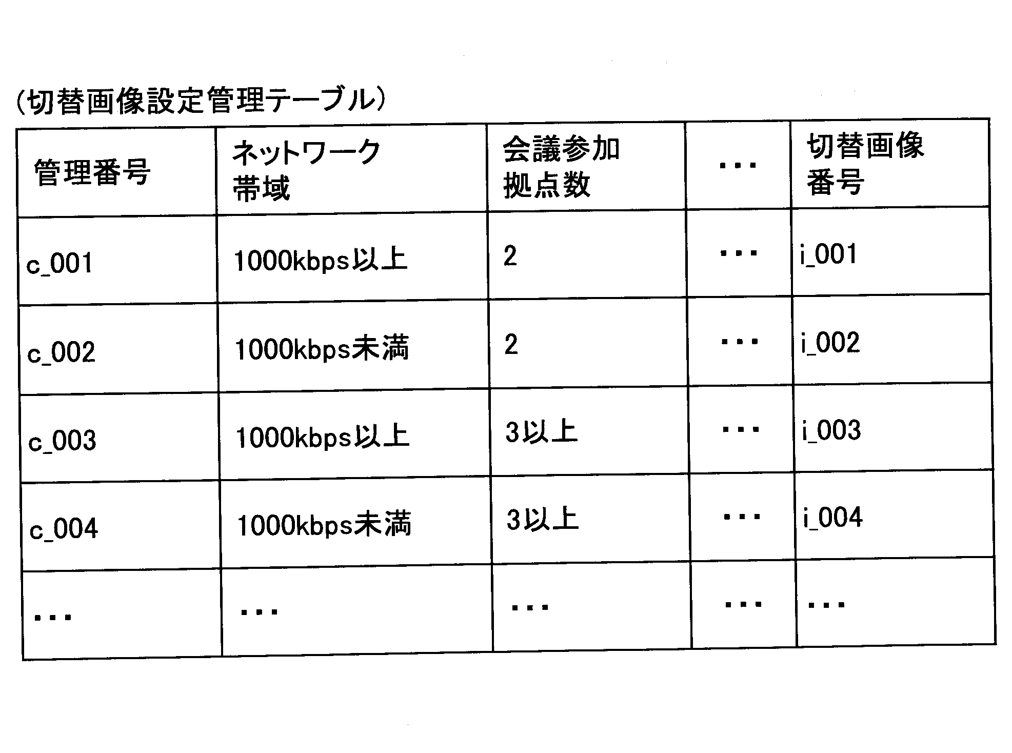
例えば、伝送端末10が通信を行なっているネットワーク帯域が1000kbps以上で、会議に参加している拠点数が2拠点だった場合、後述する切替画像決定部21は切替画像番号がi_001の切替画像を使用すると決定する。切替画像番号が決まるので切替画像決定部21は切替画像管理テーブルから切替画像を読み出すことができる。
For example, when the network bandwidth in which the transmission terminal 10 is communicating is 1000 kbps or more and the number of bases participating in the conference is two bases, the switching image determination unit 21 described later has a switching image with a switching image number i_001. Decide to use. Since the switching image number is determined, the switching image determination unit 21 can read the switching image from the switching image management table.
ここでネットワーク帯域が挙げられているのは、ネットワーク帯域によって通信PFの切り替えに要する時間が変わりやすいためである。また、会議参加拠点数が多いほどセッションを確立する時間が長くなる傾向がある。また、切り替え時間が長くても、動画であれば伝送端末10が表示する切替画面に変化が生じるため、ユーザが通信や伝送端末10の不具合でないことを理解しやすくなる。切り替え時間が短ければ、切替画面601の静止画が表示される時間もが短いのでユーザが不具合が生じたのかと誤解する前に通信PFの切り替えが完了する(動画が表示されてもすぐに終了してしまうので却って違和感を感じやすくなる)。したがって、ネットワーク帯域と会議参加拠点数に応じて、静止画や動画を切り替えることで、伝送端末10は通信PFの切り替え中であることをより適切にユーザに通知できる。
The network band is listed here because the time required to switch the communication PF is easily changed depending on the network band. Also, as the number of conference participants increases, the time to establish a session tends to be longer. In addition, even if the switching time is long, if it is a moving image, the switching screen displayed by the transmission terminal 10 changes, so that the user can easily understand that it is not a malfunction of the communication or the transmission terminal 10. If the switching time is short, the time during which the still image of the switching screen 601 is displayed is also short, and switching of the communication PF is completed before the user misunderstands whether a problem has occurred (even if the moving image is displayed, It will make you feel uncomfortable instead. Therefore, the transmission terminal 10 can more appropriately notify the user that the communication PF is being switched, by switching the still image or the moving image according to the network band and the number of the conference participants.
なお、表2では切替画像を決定するためのパラメータとして、ネットワーク帯域と会議参加拠点数を例として挙げているが、どの切替画像に決定するかのパラメータはこれらに限定されない。この他、通信PFの切り替えに要する時間に影響(相関)するパラメータ(伝送管理システム50の負荷レベルなど)が切替画像設定管理テーブルに登録されていてよい。
In Table 2, as a parameter for determining the switching image, the network band and the number of conference participants are listed as an example, but the parameters for determining which switching image is not limited to these. In addition, a parameter (such as load level of the transmission management system 50) that affects (correlates) the time required to switch the communication PF may be registered in the switching image setting management table.
また、不揮発性記憶部1000には、端末用プログラム1100が記憶されている。端末用プログラム1100はプログラム提供システム90から配信される他、インストール可能な形式又は実行可能な形式のファイルで、上記記録メディア106等のコンピュータで読み取り可能な記録媒体に記録して流通させるようにしてもよい。
(伝送端末の機能)
伝送端末10の送受信部11は、図7に示されているCPU101からの命令、及び図7に示されているネットワークI/F111によって実現され、通信ネットワーク2を介して他の伝送端末10、伝送管理システム50,及び中継装置30等と各種データの送受信を行う。 Further, thenon-volatile storage unit 1000 stores a terminal program 1100. The terminal program 1100 is distributed from the program providing system 90 and is also stored in a computer readable recording medium such as the recording medium 106 and distributed as an installable or executable file. It is also good.
(Function of transmission terminal)
The transmission /reception unit 11 of the transmission terminal 10 is realized by an instruction from the CPU 101 shown in FIG. 7 and the network I / F 111 shown in FIG. 7 and transmits the other transmission terminal 10 via the communication network 2 It transmits and receives various data with the management system 50 and the relay device 30 and the like.
(伝送端末の機能)
伝送端末10の送受信部11は、図7に示されているCPU101からの命令、及び図7に示されているネットワークI/F111によって実現され、通信ネットワーク2を介して他の伝送端末10、伝送管理システム50,及び中継装置30等と各種データの送受信を行う。 Further, the
(Function of transmission terminal)
The transmission /
送受信部11にはα用機能部11aとβ用機能部11bが接続されている。α用機能部11aはαの通信PFに必要な処理を行い、β用機能部11bはβの通信PFに必要な処理を行う。α用機能部11aは、例えば、WebRTCで用いられるグローバルIPアドレスとポート番号を宛先に通信を行い、β用機能部11bは、中継装置30のIPアドレス(グローバルIPアドレスでもプライベートIPアドレスでもよい)を宛先に通信を行う。また、αの通信PFとβの通信PFの通信プロトコルが異なる場合は、α用機能部11aはαの通信PFに用いられる通信プロトコルで通信し、β用機能部11bはβの通信PFに用いられる通信プロトコルで通信する。さらに、αの通信PFとβの通信PFの映像や音声の圧縮方式が異なる場合、α用機能部11aはαの通信PFに用いられる圧縮方式で圧縮された映像や音声を圧縮・伸張する。β用機能部11bはβの通信PFに用いられる圧縮方式で圧縮された映像や音声を圧縮・伸張する。
The transmitter / receiver unit 11 is connected to an α function unit 11 a and a β function unit 11 b. The function unit for α 11 a performs processing necessary for the communication PF for α, and the function unit for β 11 b performs processing necessary for the communication PF for β. The function unit 11a for α communicates with, for example, the global IP address and port number used in WebRTC, and the function unit 11b for β is the IP address of the relay apparatus 30 (a global IP address or a private IP address may be used) Communicate to the destination. If the communication protocols of the communication PF of α and the communication PF of β are different, the α function unit 11a communicates using the communication protocol used for the α communication PF, and the β function unit 11b uses the β for communication PF Communicate with the communication protocol. Furthermore, when the compression method of the video and audio of the communication PF of α and the communication PF of β is different, the α functional unit 11a compresses and expands the video and audio compressed by the compression method used for the communication PF of α. The function unit 11 b for β compresses / decompresses video and audio compressed by the compression method used for the communication PF of β.
表示制御部12は、図7に示されているCPU101からの命令、及び図7に示されているディスプレイI/F117によって実現され、外付けのディスプレイ120に対して画像データを送信(出力)するための制御を行う。
The display control unit 12 is realized by an instruction from the CPU 101 shown in FIG. 7 and the display I / F 117 shown in FIG. 7 and transmits (outputs) image data to the external display 120. To control.
撮像部13は、図7に示されているCPU101からの命令、及びカメラ112及び撮像素子I/F113によって実現され、被写体を撮像して、この撮像して得た画像データを出力する。
The imaging unit 13 is realized by an instruction from the CPU 101 illustrated in FIG. 7 and the camera 112 and the imaging device I / F 113, captures an image of a subject, and outputs image data obtained by capturing the image.
音声入力部14aは、図7に示されているCPU101からの命令、及び音声入出力I/F116によって実現され、マイク114によってユーザの音声が音声信号に変換された後、この音声信号に係る音声データを入力する。
The voice input unit 14a is realized by an instruction from the CPU 101 shown in FIG. 7 and the voice input / output I / F 116, and after the user's voice is converted into a voice signal by the microphone 114, the voice related to the voice signal Enter data.
音声出力部14bは、図7に示されているCPU101からの命令、及び音声入出力I/F116によって実現され、音声データに係る音声信号をスピーカ115に出力し、スピーカ115から音声を出力させる。
The audio output unit 14 b is realized by an instruction from the CPU 101 and the audio input / output I / F 116 illustrated in FIG. 7, outputs an audio signal related to audio data to the speaker 115, and causes the speaker 115 to output audio.
宛先リスト作成部15は、図7に示されているCPU101からの命令によって実現され、伝送管理システム50から受信した宛先状態情報(宛先候補端末及び宛先候補の伝送端末10及び携帯端末20の稼動状態)に基づいて、宛先リストの作成及び更新を行う。
The destination list creation unit 15 is realized by an instruction from the CPU 101 shown in FIG. 7 and receives the destination status information received from the transmission management system 50 (destination candidate terminal and destination candidate transmission terminal 10 and mobile terminal 20 operating status Create and update the destination list on the basis of.
操作入力受付部16は、図7に示されているCPU101からの命令、操作ボタン108及び電源スイッチ109によって実現され、ユーザによる各種入力を受け付ける。例えば、ユーザが、図7に示されている電源スイッチ109をONにすると、操作入力受付部16が電源ONを受け付けて電源をONにする。
The operation input receiving unit 16 is realized by an instruction from the CPU 101, the operation button 108, and the power switch 109 shown in FIG. 7, and receives various inputs from the user. For example, when the user turns on the power switch 109 shown in FIG. 7, the operation input receiving unit 16 receives power on and turns on the power.
ログイン要求部17は、図7に示されているCPU101からの命令によって実現され、上記電源ONの受け付けを契機として伝送管理システム50に、ログインを要求する旨を示すログイン要求情報、及び要求元端末の現時点のIPアドレスを自動的に送信する。ユーザの認証操作を契機としてもよい。また、送信時は、送受信部11が通信ネットワーク2を介して送信する。
The login request unit 17 is realized by an instruction from the CPU 101 shown in FIG. 7 and is a login request information indicating that the transmission management system 50 is requested to log in upon receipt of the power ON, and a request source terminal Automatically send the current IP address of. It may be triggered by the authentication operation of the user. Further, at the time of transmission, the transmission / reception unit 11 transmits via the communication network 2.
切替画像決定パラメータ測定部18は、切替画像決定部21が切替画像を選択するためのパラメータを測定する。パラメータは例えばネットワーク帯域や会議参加拠点数である。
The switching image determination parameter measuring unit 18 measures parameters for the switching image determining unit 21 to select a switching image. The parameters are, for example, the network bandwidth and the number of conference participants.
切替画像決定部21は図7に示されているCPU101からの命令によって実現され、通信PFが切り替えられる際、切り替えの開始から終了までの間に伝送端末10のディスプレイ120に表示する切替画像を決定する。
The switching image determination unit 21 is realized by an instruction from the CPU 101 shown in FIG. 7 and determines the switching image to be displayed on the display 120 of the transmission terminal 10 between the start and the end of switching when the communication PF is switched. Do.
記憶・読出処理部19は、図7に示されているCPU101からの命令、及び図7に示すSSD105によって実現され、不揮発性記憶部1000に各種データを記憶したり、不揮発性記憶部1000に記憶された各種データを読み出したりする処理を行う。この不揮発性記憶部1000には、通信先としての伝送端末10の端末又はユーザを識別するための通信ID(Identification)、タイプ識別情報(伝送端末10や携帯端末20の区別を示す情報)、及びパスワード等が記憶される。なお、通信ID及びパスワードは不揮発性記憶部1000に記憶されていなくてもよく、例えば伝送管理システム50に対してログイン要求を行う際に都度、ユーザが入力するようにしてもよい。
Storage / read processing unit 19 is realized by an instruction from CPU 101 shown in FIG. 7 and SSD 105 shown in FIG. 7 to store various data in nonvolatile storage unit 1000 or store in nonvolatile storage unit 1000. It performs processing to read out various data. The non-volatile storage unit 1000 includes a communication ID (Identification) for identifying the terminal or user of the transmission terminal 10 as a communication destination, type identification information (information indicating the distinction between the transmission terminal 10 and the portable terminal 20), A password or the like is stored. The communication ID and the password may not be stored in the non-volatile storage unit 1000, and may be input by the user each time a login request is made to the transmission management system 50, for example.
なお、本実施例の通信IDは、それぞれ伝送端末若しくはこの伝送端末を利用するユーザを一意に識別するために使われる言語、文字、記号、又は各種のしるし等の識別情報を示す。また、通信ID及び中継装置IDは、上記言語、文字、記号、及び各種のしるしのうち、少なくとも2つが組み合わされた識別情報であってもよい。
<<伝送管理システムの機能構成>>
伝送管理システム50は、送受信部51、PF切替判定部52、認証部53、セッション管理部54、通信状況検出部55、及び、記憶・読出処理部59を有している。これら各部は、図8に示されている各構成要素のいずれかが、HD304からRAM303上に展開されたに従ったCPU301からの命令によって動作することで実現される機能又は機能される手段である。また、伝送管理システム50は、伝送管理システム50の電源をOFFにしても各種データ(または情報)の記憶が維持される不揮発性記憶部5000を有しており、この不揮発性記憶部5000は図8に示されているHD304により構築されている。 The communication ID in the present embodiment indicates identification information such as a language, characters, symbols, or various marks used to uniquely identify a transmission terminal or a user who uses the transmission terminal. The communication ID and the relay device ID may be identification information in which at least two of the language, characters, symbols, and various marks are combined.
<< Functional Configuration of Transmission Management System >>
Thetransmission management system 50 includes a transmission / reception unit 51, a PF switching determination unit 52, an authentication unit 53, a session management unit 54, a communication status detection unit 55, and a storage / read processing unit 59. These units are functions or means implemented by any of the components shown in FIG. 8 being operated by an instruction from the CPU 301 according to the development from the HD 304 onto the RAM 303. . Further, the transmission management system 50 has a non-volatile storage unit 5000 in which storage of various data (or information) is maintained even when the power of the transmission management system 50 is turned off. This non-volatile storage unit 5000 It is constructed by the HD 304 shown in FIG.
<<伝送管理システムの機能構成>>
伝送管理システム50は、送受信部51、PF切替判定部52、認証部53、セッション管理部54、通信状況検出部55、及び、記憶・読出処理部59を有している。これら各部は、図8に示されている各構成要素のいずれかが、HD304からRAM303上に展開されたに従ったCPU301からの命令によって動作することで実現される機能又は機能される手段である。また、伝送管理システム50は、伝送管理システム50の電源をOFFにしても各種データ(または情報)の記憶が維持される不揮発性記憶部5000を有しており、この不揮発性記憶部5000は図8に示されているHD304により構築されている。 The communication ID in the present embodiment indicates identification information such as a language, characters, symbols, or various marks used to uniquely identify a transmission terminal or a user who uses the transmission terminal. The communication ID and the relay device ID may be identification information in which at least two of the language, characters, symbols, and various marks are combined.
<< Functional Configuration of Transmission Management System >>
The
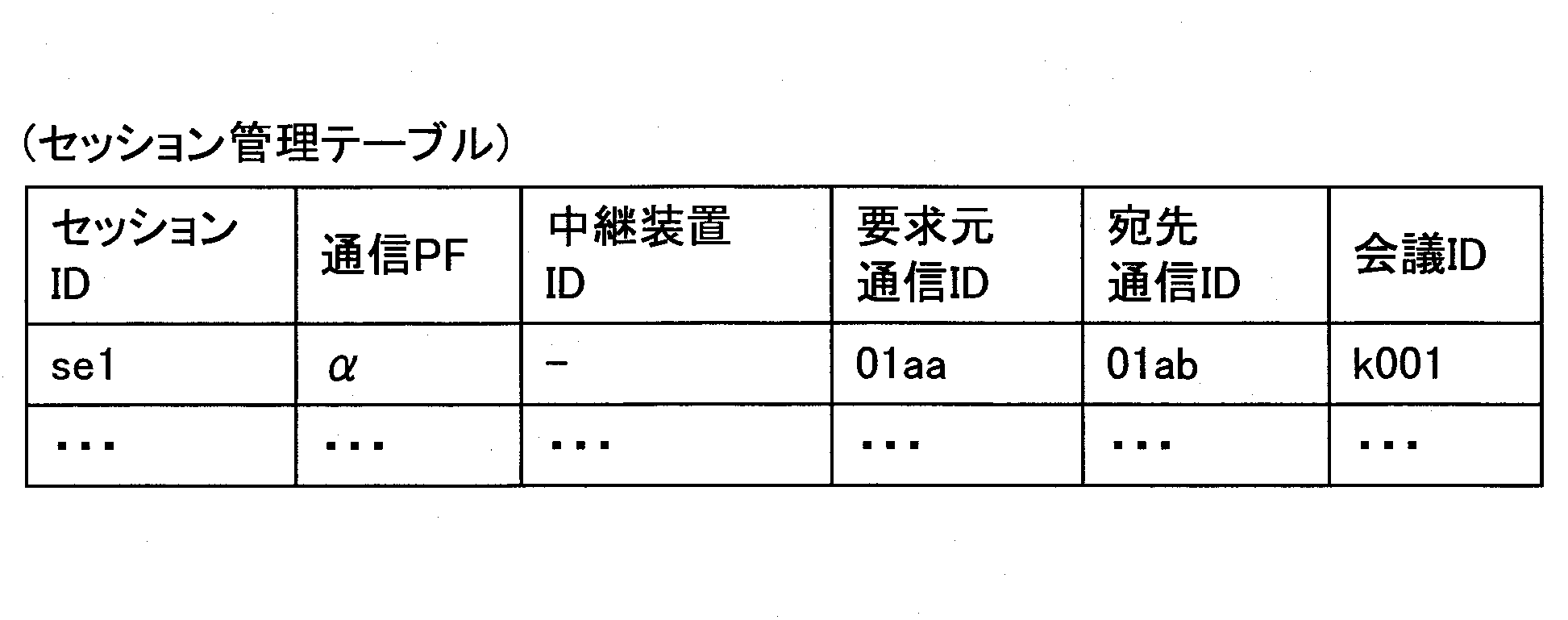
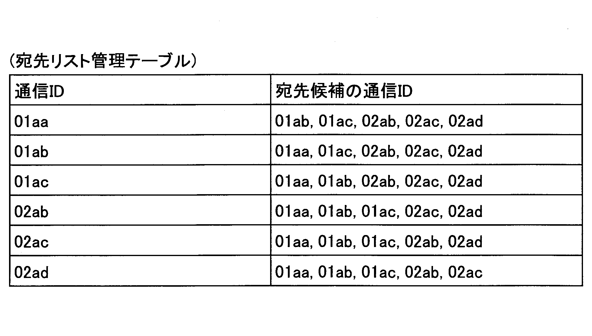


また、不揮発性記憶部5000には、伝送管理用プログラム5100が記憶されている。伝送管理用プログラム5100は、プログラム提供システム90から配信される。また、インストール可能な形式又は実行可能な形式のファイルで、上記記録メディア306やCD-ROM313等のコンピュータで読み取り可能な記録媒体に記録して流通させるようにしてもよい。
<<伝送管理システムの各機能構成>>
次に、伝送管理システム50の各機能構成について詳細に説明する。送受信部51は、図8に示されているCPU301からの命令、及び図8に示されているネットワークI/F309によって実現され、通信ネットワーク2を介して伝送端末10や中継装置30と各種データ(または情報)の送受信を行う。 Further, in thenon-volatile storage unit 5000, a transmission management program 5100 is stored. The transmission management program 5100 is distributed from the program providing system 90. Alternatively, a file in an installable format or an executable format may be recorded and distributed in a computer readable recording medium such as the recording medium 306 or the CD-ROM 313.
<< Functional Configuration of Transmission Management System >>
Next, each functional configuration of thetransmission management system 50 will be described in detail. The transmission / reception unit 51 is realized by an instruction from the CPU 301 shown in FIG. 8 and the network I / F 309 shown in FIG. 8 and transmits various data (the transmission terminal 10 and the relay device 30 via the communication network 2). Or send and receive information).
<<伝送管理システムの各機能構成>>
次に、伝送管理システム50の各機能構成について詳細に説明する。送受信部51は、図8に示されているCPU301からの命令、及び図8に示されているネットワークI/F309によって実現され、通信ネットワーク2を介して伝送端末10や中継装置30と各種データ(または情報)の送受信を行う。 Further, in the
<< Functional Configuration of Transmission Management System >>
Next, each functional configuration of the
認証部53は、図8に示されているCPU301からの命令等によって実現される。認証部53は、送受信部51を介して受信されたログイン要求情報に含まれている通信ID及びパスワードの組み合わせが認証管理DB5004に登録されているものと一致するか否かに応じて伝送端末10又はユーザを認証する。なお、認証方法はこれに限られず、クライアント証明書(公開鍵と秘密鍵を用いた認証方法)を用いてもよい。
Authentication unit 53 is realized by an instruction or the like from CPU 301 shown in FIG. The authentication unit 53 determines whether the combination of the communication ID and the password included in the login request information received via the transmission and reception unit 51 matches the one registered in the authentication management DB 5004 or not. Or authenticate the user. The authentication method is not limited to this, and a client certificate (an authentication method using a public key and a secret key) may be used.
セッション管理部54は、図8に示されているCPU301からの命令によって実現される。セッション管理部54は、認証部53により認証が成立した伝送端末10から宛先端末との接続を要求されると(開始要求情報を取得すると)、セッション管理DB5001に、通信PF、コンテンツデータを中継する中継装置30の中継装置ID(中継装置30が中継する場合)、セッションID、要求元端末の通信ID、宛先端末の通信ID及び会議IDを関連付けて記憶して管理する。なお、セッション管理部54は通信PFごとに適切なセッションを確立するが詳細は後述する。
The session management unit 54 is realized by an instruction from the CPU 301 shown in FIG. The session management unit 54 relays the communication PF and content data to the session management DB 5001 when a connection with the destination terminal is requested from the transmission terminal 10 for which authentication has been established by the authentication unit 53 (when start request information is acquired). The relay device ID of the relay device 30 (when the relay device 30 relays), the session ID, the communication ID of the request source terminal, the communication ID of the destination terminal, and the conference ID are stored in association with one another and managed. The session management unit 54 establishes an appropriate session for each communication PF, the details of which will be described later.
通信状況検出部55は、図8に示されているCPU301からの命令によって実現され、伝送端末10同士及び伝送端末10と伝送管理システム50間の通信状況を検出する。本実施例の通信状況の一例としてはネットワーク帯域や拠点数(会議参加拠点数)が上げられる。
The communication status detection unit 55 is realized by an instruction from the CPU 301 shown in FIG. 8 and detects the communication status between the transmission terminals 10 and between the transmission terminal 10 and the transmission management system 50. As an example of the communication state of the present embodiment, the network bandwidth and the number of bases (the number of meeting participating bases) can be raised.
PF切替判定部52は、図8に示されているCPU301からの命令によって実現され、通信状況に応じてPF判定テーブルを参照して適切な通信PFを選択する(決定する)。通信PFの決定や切り替えの判断について詳細は後述する。通信PFを切り替えると判断した場合、セッション管理部54に切り替え後の通信PFを通知してセッションの確立を要求する。
The PF switching determination unit 52 is realized by an instruction from the CPU 301 shown in FIG. 8 and selects (determines) an appropriate communication PF with reference to the PF determination table according to the communication status. Details of the determination of the communication PF and the determination of switching will be described later. If it is determined that the communication PF is to be switched, the session management unit 54 is notified of the communication PF after switching, and the session establishment is requested.
記憶・読出処理部59は、図8に示されているCPU301からの命令、及び図8に示されているHDD305によって実現され、不揮発性記憶部5000に各種データを記憶したり、不揮発性記憶部5000に記憶された各種データを読み出したりする処理を行う。
<<通信PFに応じたセッションの確立について>>
まず、αの通信PFで用いられるWebRTCのセッションの確立について簡単に説明する。WebRTCでは例えばブラウザ(あるいはこれと同等の機能を持つアプリ)同士がサーバを介さずに通信する。しかし、通信相手を特定する処理(シグナリング)が必要であるため、伝送管理システム50は端末管理テーブルで伝送端末10の稼動状態を管理していることを利用して一方のユーザが宛先となる他方のユーザを特定することを可能にする。例えば後述の宛先リスト画面により宛先のユーザを特定できる。互いに通信する2つの伝送端末10を特定できると、セッション管理部54はSTUNサーバとして機能する。そして、相手側の伝送端末10が配置されている社内ネットワークや家庭内ネットワークのNAT(Network Address Translation)装置の外側のグローバルIPアドレスとポート番号を伝送端末10aaと10abに通知する。伝送端末10aaと10abは相手のグローバルIPアドレスとポート番号が分かるのでNAT装置を超えて1対1の通信が可能になる。 Storage /read processing unit 59 is realized by an instruction from CPU 301 shown in FIG. 8 and HDD 305 shown in FIG. 8, stores various data in nonvolatile storage unit 5000, and nonvolatile storage unit A process of reading out various data stored in 5000 is performed.
<< About establishment of session according to communication PF >>
First, establishment of a WebRTC session used in the communication PF of α will be briefly described. In WebRTC, for example, browsers (or applications having functions equivalent to this) communicate with each other without passing through a server. However, since the process (signaling) for specifying the communication partner is necessary, thetransmission management system 50 uses the fact that the operation state of the transmission terminal 10 is managed in the terminal management table, and the other user is addressed to the other Allows to identify the user of. For example, the destination user can be specified by a destination list screen described later. When the two transmission terminals 10 communicating with each other can be specified, the session management unit 54 functions as a STUN server. Then, the transmission terminals 10aa and 10ab are notified of the global IP address and port number outside the NAT (Network Address Translation) apparatus of the in-house network or the home network in which the transmission terminal 10 on the opposite side is arranged. Since the transmission terminals 10aa and 10ab know the other party's global IP address and port number, one-to-one communication becomes possible beyond the NAT device.
<<通信PFに応じたセッションの確立について>>
まず、αの通信PFで用いられるWebRTCのセッションの確立について簡単に説明する。WebRTCでは例えばブラウザ(あるいはこれと同等の機能を持つアプリ)同士がサーバを介さずに通信する。しかし、通信相手を特定する処理(シグナリング)が必要であるため、伝送管理システム50は端末管理テーブルで伝送端末10の稼動状態を管理していることを利用して一方のユーザが宛先となる他方のユーザを特定することを可能にする。例えば後述の宛先リスト画面により宛先のユーザを特定できる。互いに通信する2つの伝送端末10を特定できると、セッション管理部54はSTUNサーバとして機能する。そして、相手側の伝送端末10が配置されている社内ネットワークや家庭内ネットワークのNAT(Network Address Translation)装置の外側のグローバルIPアドレスとポート番号を伝送端末10aaと10abに通知する。伝送端末10aaと10abは相手のグローバルIPアドレスとポート番号が分かるのでNAT装置を超えて1対1の通信が可能になる。 Storage /
<< About establishment of session according to communication PF >>
First, establishment of a WebRTC session used in the communication PF of α will be briefly described. In WebRTC, for example, browsers (or applications having functions equivalent to this) communicate with each other without passing through a server. However, since the process (signaling) for specifying the communication partner is necessary, the
次に、βの通信PFで用いられるセッションの確立について簡単に説明する。伝送管理システム50にログインした伝送端末10の稼動状態が端末管理テーブルにて管理されるまでは同じである。この後、例えば伝送端末10aaのユーザが通信相手として伝送端末10abを伝送管理システム50に通知すると、セッション管理部54は適切な中継装置30を選択する。中継装置30をどのように選択するかは種々の方法が考えられるが、本実施例では中継装置30から伝送端末10までの伝送の遅延時間などが考慮される。
Next, establishment of a session used in the communication PF of β will be briefly described. It is the same until the operation state of the transmission terminal 10 logged in to the transmission management system 50 is managed by the terminal management table. After that, for example, when the user of the transmission terminal 10aa notifies the transmission management system 50 of the transmission terminal 10ab as a communication partner, the session management unit 54 selects an appropriate relay device 30. Although various methods can be considered as how to select the relay apparatus 30, the delay time of the transmission from the relay apparatus 30 to the transmission terminal 10 etc. are considered in a present Example.
セッション管理部54は中継装置30を決定すると1つのテレビ会議で通信する伝送端末10aa、10abの通信IDを中継装置30に通知する。セッション管理部54又は中継装置30はこれらにセッションIDを採番すると共に同じ会議に参加するものとして会議IDを割り当てる。また、セッション管理部54は伝送端末10aa、10abに中継装置30のIPアドレスを通知する。伝送端末10aa、10abが通信IDと共に中継装置30に接続すると、中継装置30は通信IDに基づいて同じテレビ会議に参加している伝送端末10aa、10abにコンテンツデータを中継する。
<伝送端末10の通信処理>
図10を用いて伝送端末10aaと10abがセッションを確立する手順を説明する。図10は、伝送端末10aaと10abがセッションを確立する手順を示すシーケンス図の一例である。なお、本実施例では、2つ伝送端末10がテレビ会議を開始する場合には、αの通信PFを使用するものとする。しかし、例えばユーザが3人以上でテレビ会議を行う予定がある場合などに伝送システム1が対応するために、ユーザが指定した通信PFでテレビ会議を開始してもよい。ユーザはβの通信PFを伝送管理システム50に指定することで、βの通信PFでテレビ会議を開始できる。
S1:ユーザが電源スイッチ109をONにすると、操作入力受付部16が電源ONを受け付けて、電源をONにする。
S2:ログイン要求部17は上記電源ONを契機とし、送受信部11から通信ネットワーク2を介して伝送管理システム50にログイン要求を示すログイン要求情報を自動的に送信する。ログイン要求は電源ON時だけでなくユーザ操作によって任意のタイミングで送信されることができる。ログイン要求情報には、要求元である伝送端末10aaを識別するための通信ID、及びパスワードが含まれている。なお、伝送端末10aaから伝送管理システム50へログイン要求情報が送信される際、受信側である伝送管理システム50は、伝送端末10aaのIPアドレス(グローバルIPアドレス)を把握することができる。
S3:伝送管理システム50の認証部53は、送受信部51を介して受信したログイン要求情報に含まれている通信ID及びパスワードと同一の通信ID及びパスワードが認証管理テーブルで管理されているかを判断することによって端末認証を行う。
S4:認証部53によって伝送端末10aaの認証が成立した場合、セッション管理部54は宛先管理テーブルから伝送端末10aaが宛先候補とする宛先端末の通信IDを読み出し、宛先端末の稼動状態を端末管理テーブルから読み出す。本処理では宛先端末である伝送端末10abはオンラインであるとする。
S5:次に、送受信部51は、宛先候補の各伝送端末の通信IDと稼動状態とが含まれた宛先状態情報を、通信ネットワーク2を介して伝送端末10aaに送信する。宛先状態情報には、端末管理テーブルに登録されている名称が含まれる。これにより、伝送端末10aaは、伝送端末10aaと通信することができる宛先リストの伝送端末10abの現時点の稼動状態を把握することができる。
S6:なお、送受信部51はログイン要求してきた伝送端末10aaの通信IDとその稼動状態を、伝送端末10aaを宛先リストに含める伝送端末(ここでは伝送端末10ab)に送信する。これにより、宛先リストに登録されている宛先候補の伝送端末10が互いに相手の稼動状態を把握できる。
S7:伝送端末10aaの宛先リスト作成部15は、宛先状態情報を受け取ると、宛先リストを作成し、ディスプレイ120に表示させる。伝送端末10aaのユーザは宛先リスト画面から通信の開始を要求する通信IDを選択することができる。本実施例では伝送端末10abが選択されたものとする。
S8:ユーザが宛先を選択して通信の開始を要求すると、伝送端末10aaの送受信部11は、開始要求情報を伝送管理システム50へ送信する。開始要求情報には要求元通信IDと宛先通信IDが含まれる。また、これにより、伝送管理システム50の送受信部51は要求元端末10aaのIPアドレスを把握することになる。
S9:伝送管理システム50のセッション管理部54は、セッションを確立するための処理を行う。すなわち、セッション管理テーブルにセッションID、通信PF、要求元通信ID、宛先通信ID及び会議IDを登録する。また、端末管理テーブルの伝送端末10aaと10abに対応づけて、稼動状態を「通信中」に設定する。
S10、S11:伝送管理システム50のセッション管理部54は、上記したNUT越えのために伝送端末10aaと10abにそれぞれ相手のグローバルIPアドレスとポート番号を通知する。
S12:これにより、伝送端末10aaと10abはαの通信PFで通信を開始できる。
<<通信PFの切替>>
次に、図11を用いて通信PFの切り替え手順について説明する。図11は、通信PFの切り替え手順を示すシーケンス図の一例である。切り替え前、伝送端末10aaと10abはαの通信PFで通信しており、会議中画面602を表示している。
S1:伝送端末10acは伝送端末10aa、10abと同様に伝送管理システム50にログインし、宛先リストを表示する。これにより、伝送端末10acは伝送管理システム50に対し伝送端末10aaを宛先端末とする開始要求情報を送信する。なお、伝送端末10aaがセッションIDを通知することで伝送端末10acをテレビ会議に招待してもよい。
S2:伝送端末10acの送受信部11は、開始要求情報を伝送管理システム50へ送信する。開始要求情報には要求元通信IDと宛先通信IDが含まれる。また、これにより、伝送管理システム50の送受信部51は要求元端末10acのIPアドレスを把握することになる。
S3:伝送管理システム50のPF切替判定部52は、通信状況検出部55が検出する通信状況に基づき通信PFを切り替えるか否かを判定する。伝送端末10acからの開始要求情報により伝送端末10acと伝送端末10aaは同じテレビ会議に参加することが分かる。また、すでに伝送端末10aaとテレビ会議している伝送端末10abをセッション管理テーブルの会議IDに基づいてカウントする。よって拠点数は3に増える。PF判定テーブルによれば拠点数が3以上の場合、通信PFをβに切り替えると判断される。なお、図16では伝送端末10acがαの通信PFで通信する前に通信PFが切り替えられているが、伝送端末10acがαの通信PFでテレビ会議に参加した後に通信PFが切り替えられてもよい。
S4、S5:PF切替判定部52は送受信部51を介して切替開始通知を伝送端末10aaと10abに送信する。
S6,S7:伝送端末10aa、10abは会議中画面602の表示を終了させて切替画面601を表示する処理を行う。この処理については後述する。
S8:次に、セッション管理部54はセッション管理テーブルを更新する。表6に更新後のセッション管理テーブルを示す。 When determining therelay device 30, the session management unit 54 notifies the relay device 30 of the communication IDs of the transmission terminals 10aa and 10ab communicating in one video conference. The session management unit 54 or the relay device 30 numbers the session ID and assigns the conference ID as participating in the same conference. The session management unit 54 also notifies the transmission terminals 10aa and 10ab of the IP address of the relay apparatus 30. When the transmission terminals 10aa and 10ab connect to the relay device 30 together with the communication ID, the relay device 30 relays the content data to the transmission terminals 10aa and 10ab participating in the same video conference based on the communication ID.
<Communication Processing ofTransmission Terminal 10>
The procedure in which the transmission terminals 10aa and 10ab establish a session will be described using FIG. FIG. 10 is an example of a sequence diagram showing a procedure in which the transmission terminals 10aa and 10ab establish a session. In the present embodiment, when the twotransmission terminals 10 start a video conference, the communication PF of α is used. However, for example, the video conference may be started by the communication PF designated by the user in order for the transmission system 1 to cope with the case where the video conference is scheduled to be performed by three or more users. The user can start a video conference on the communication PF of β by specifying the communication PF of β as the transmission management system 50.
S1: When the user turns on thepower switch 109, the operation input receiving unit 16 receives power on and turns on the power.
S2: Thelogin request unit 17 automatically sends login request information indicating a login request to the transmission management system 50 from the transmission / reception unit 11 via the communication network 2 when the power is turned on. The login request can be transmitted at any timing by user operation as well as when the power is turned on. The login request information includes a communication ID for identifying the transmission terminal 10aa that is the request source, and a password. When log-in request information is transmitted from the transmission terminal 10aa to the transmission management system 50, the transmission management system 50 on the receiving side can grasp the IP address (global IP address) of the transmission terminal 10aa.
S3: Theauthentication unit 53 of the transmission management system 50 determines whether the same communication ID and password as the communication ID and password contained in the login request information received via the transmission / reception unit 51 are managed in the authentication management table. Perform terminal authentication by doing this.
S4: When the authentication of the transmission terminal 10aa is established by theauthentication unit 53, the session management unit 54 reads the communication ID of the destination terminal that the transmission terminal 10aa takes as a destination candidate from the destination management table, and the operation status of the destination terminal is the terminal management table. Read from In this process, it is assumed that the transmission terminal 10ab which is the destination terminal is online.
S5: Next, the transmission /reception unit 51 transmits, to the transmission terminal 10aa via the communication network 2, the destination state information including the communication ID and the operation state of each transmission terminal of the destination candidate. The destination state information includes the name registered in the terminal management table. Thereby, the transmission terminal 10aa can grasp the current operation state of the transmission terminal 10ab of the destination list that can communicate with the transmission terminal 10aa.
S6: The transmitting and receivingunit 51 transmits the communication ID of the transmission terminal 10aa that has made the login request and the operation state thereof to the transmission terminal (here, the transmission terminal 10ab) that includes the transmission terminal 10aa in the destination list. Thereby, the transmission terminals 10 of the destination candidate registered in the destination list can mutually grasp the operation state of the other party.
S7: When receiving the destination status information, the destinationlist creation unit 15 of the transmission terminal 10aa creates a destination list and causes the display 120 to display the destination list. The user of the transmission terminal 10aa can select a communication ID for requesting start of communication from the destination list screen. In the present embodiment, it is assumed that the transmission terminal 10ab is selected.
S8: When the user selects a destination and requests the start of communication, the transmission /reception unit 11 of the transmission terminal 10aa transmits start request information to the transmission management system 50. The start request information includes a request source communication ID and a destination communication ID. Further, as a result, the transmission / reception unit 51 of the transmission management system 50 recognizes the IP address of the request source terminal 10aa.
S9: The session management unit 54 of thetransmission management system 50 performs processing for establishing a session. That is, the session ID, the communication PF, the request source communication ID, the destination communication ID, and the conference ID are registered in the session management table. Further, the operation status is set to "in communication" in association with the transmission terminals 10aa and 10ab in the terminal management table.
S10, S11: The session management unit 54 of thetransmission management system 50 notifies the transmission terminals 10aa and 10ab of the other party's global IP address and port number, respectively, for the NUT crossing described above.
S12: With this, the transmission terminals 10aa and 10ab can start communication with the communication PF of α.
<< Switching of communication PF >>
Next, the switching procedure of the communication PF will be described using FIG. FIG. 11 is an example of a sequence diagram showing a switching procedure of the communication PF. Before switching, the transmission terminals 10aa and 10ab communicate by the communication PF of α, and the in-meeting screen 602 is displayed.
S1: The transmission terminal 10ac logs in to thetransmission management system 50 in the same manner as the transmission terminals 10aa and 10ab, and displays the destination list. As a result, the transmission terminal 10 ac transmits, to the transmission management system 50, start request information in which the transmission terminal 10 aa is the destination terminal. The transmission terminal 10aa may invite the transmission terminal 10ac to a video conference by notifying the session ID.
S2: The transmission /reception unit 11 of the transmission terminal 10ac transmits start request information to the transmission management system 50. The start request information includes a request source communication ID and a destination communication ID. Further, as a result, the transmission / reception unit 51 of the transmission management system 50 recognizes the IP address of the request source terminal 10ac.
S3: The PF switching determination unit 52 of thetransmission management system 50 determines whether to switch the communication PF based on the communication status detected by the communication status detection unit 55. It can be understood from the start request information from the transmission terminal 10 ac that the transmission terminal 10 ac and the transmission terminal 10 aa participate in the same video conference. In addition, the transmission terminal 10ab that has already been teleconferenceed with the transmission terminal 10aa is counted based on the meeting ID of the session management table. Therefore, the number of bases will increase to three. According to the PF determination table, when the number of bases is 3 or more, it is determined that the communication PF is switched to β. In FIG. 16, the communication PF is switched before the transmission terminal 10ac communicates with the communication PF of α, but the communication PF may be switched after the transmission terminal 10ac participates in a video conference by the communication PF of α. .
S4, S5: The PF switching determination unit 52 transmits a switching start notification to the transmission terminals 10aa and 10ab via the transmission /reception unit 51.
S6, S7: The transmission terminals 10aa, 10ab end the display of the in-meeting screen 602 and perform processing to display the switching screen 601. This process will be described later.
S8: Next, the session management unit 54 updates the session management table. Table 6 shows the updated session management table.
<伝送端末10の通信処理>
図10を用いて伝送端末10aaと10abがセッションを確立する手順を説明する。図10は、伝送端末10aaと10abがセッションを確立する手順を示すシーケンス図の一例である。なお、本実施例では、2つ伝送端末10がテレビ会議を開始する場合には、αの通信PFを使用するものとする。しかし、例えばユーザが3人以上でテレビ会議を行う予定がある場合などに伝送システム1が対応するために、ユーザが指定した通信PFでテレビ会議を開始してもよい。ユーザはβの通信PFを伝送管理システム50に指定することで、βの通信PFでテレビ会議を開始できる。
S1:ユーザが電源スイッチ109をONにすると、操作入力受付部16が電源ONを受け付けて、電源をONにする。
S2:ログイン要求部17は上記電源ONを契機とし、送受信部11から通信ネットワーク2を介して伝送管理システム50にログイン要求を示すログイン要求情報を自動的に送信する。ログイン要求は電源ON時だけでなくユーザ操作によって任意のタイミングで送信されることができる。ログイン要求情報には、要求元である伝送端末10aaを識別するための通信ID、及びパスワードが含まれている。なお、伝送端末10aaから伝送管理システム50へログイン要求情報が送信される際、受信側である伝送管理システム50は、伝送端末10aaのIPアドレス(グローバルIPアドレス)を把握することができる。
S3:伝送管理システム50の認証部53は、送受信部51を介して受信したログイン要求情報に含まれている通信ID及びパスワードと同一の通信ID及びパスワードが認証管理テーブルで管理されているかを判断することによって端末認証を行う。
S4:認証部53によって伝送端末10aaの認証が成立した場合、セッション管理部54は宛先管理テーブルから伝送端末10aaが宛先候補とする宛先端末の通信IDを読み出し、宛先端末の稼動状態を端末管理テーブルから読み出す。本処理では宛先端末である伝送端末10abはオンラインであるとする。
S5:次に、送受信部51は、宛先候補の各伝送端末の通信IDと稼動状態とが含まれた宛先状態情報を、通信ネットワーク2を介して伝送端末10aaに送信する。宛先状態情報には、端末管理テーブルに登録されている名称が含まれる。これにより、伝送端末10aaは、伝送端末10aaと通信することができる宛先リストの伝送端末10abの現時点の稼動状態を把握することができる。
S6:なお、送受信部51はログイン要求してきた伝送端末10aaの通信IDとその稼動状態を、伝送端末10aaを宛先リストに含める伝送端末(ここでは伝送端末10ab)に送信する。これにより、宛先リストに登録されている宛先候補の伝送端末10が互いに相手の稼動状態を把握できる。
S7:伝送端末10aaの宛先リスト作成部15は、宛先状態情報を受け取ると、宛先リストを作成し、ディスプレイ120に表示させる。伝送端末10aaのユーザは宛先リスト画面から通信の開始を要求する通信IDを選択することができる。本実施例では伝送端末10abが選択されたものとする。
S8:ユーザが宛先を選択して通信の開始を要求すると、伝送端末10aaの送受信部11は、開始要求情報を伝送管理システム50へ送信する。開始要求情報には要求元通信IDと宛先通信IDが含まれる。また、これにより、伝送管理システム50の送受信部51は要求元端末10aaのIPアドレスを把握することになる。
S9:伝送管理システム50のセッション管理部54は、セッションを確立するための処理を行う。すなわち、セッション管理テーブルにセッションID、通信PF、要求元通信ID、宛先通信ID及び会議IDを登録する。また、端末管理テーブルの伝送端末10aaと10abに対応づけて、稼動状態を「通信中」に設定する。
S10、S11:伝送管理システム50のセッション管理部54は、上記したNUT越えのために伝送端末10aaと10abにそれぞれ相手のグローバルIPアドレスとポート番号を通知する。
S12:これにより、伝送端末10aaと10abはαの通信PFで通信を開始できる。
<<通信PFの切替>>
次に、図11を用いて通信PFの切り替え手順について説明する。図11は、通信PFの切り替え手順を示すシーケンス図の一例である。切り替え前、伝送端末10aaと10abはαの通信PFで通信しており、会議中画面602を表示している。
S1:伝送端末10acは伝送端末10aa、10abと同様に伝送管理システム50にログインし、宛先リストを表示する。これにより、伝送端末10acは伝送管理システム50に対し伝送端末10aaを宛先端末とする開始要求情報を送信する。なお、伝送端末10aaがセッションIDを通知することで伝送端末10acをテレビ会議に招待してもよい。
S2:伝送端末10acの送受信部11は、開始要求情報を伝送管理システム50へ送信する。開始要求情報には要求元通信IDと宛先通信IDが含まれる。また、これにより、伝送管理システム50の送受信部51は要求元端末10acのIPアドレスを把握することになる。
S3:伝送管理システム50のPF切替判定部52は、通信状況検出部55が検出する通信状況に基づき通信PFを切り替えるか否かを判定する。伝送端末10acからの開始要求情報により伝送端末10acと伝送端末10aaは同じテレビ会議に参加することが分かる。また、すでに伝送端末10aaとテレビ会議している伝送端末10abをセッション管理テーブルの会議IDに基づいてカウントする。よって拠点数は3に増える。PF判定テーブルによれば拠点数が3以上の場合、通信PFをβに切り替えると判断される。なお、図16では伝送端末10acがαの通信PFで通信する前に通信PFが切り替えられているが、伝送端末10acがαの通信PFでテレビ会議に参加した後に通信PFが切り替えられてもよい。
S4、S5:PF切替判定部52は送受信部51を介して切替開始通知を伝送端末10aaと10abに送信する。
S6,S7:伝送端末10aa、10abは会議中画面602の表示を終了させて切替画面601を表示する処理を行う。この処理については後述する。
S8:次に、セッション管理部54はセッション管理テーブルを更新する。表6に更新後のセッション管理テーブルを示す。 When determining the
<Communication Processing of
The procedure in which the transmission terminals 10aa and 10ab establish a session will be described using FIG. FIG. 10 is an example of a sequence diagram showing a procedure in which the transmission terminals 10aa and 10ab establish a session. In the present embodiment, when the two
S1: When the user turns on the
S2: The
S3: The
S4: When the authentication of the transmission terminal 10aa is established by the
S5: Next, the transmission /
S6: The transmitting and receiving
S7: When receiving the destination status information, the destination
S8: When the user selects a destination and requests the start of communication, the transmission /
S9: The session management unit 54 of the
S10, S11: The session management unit 54 of the
S12: With this, the transmission terminals 10aa and 10ab can start communication with the communication PF of α.
<< Switching of communication PF >>
Next, the switching procedure of the communication PF will be described using FIG. FIG. 11 is an example of a sequence diagram showing a switching procedure of the communication PF. Before switching, the transmission terminals 10aa and 10ab communicate by the communication PF of α, and the in-
S1: The transmission terminal 10ac logs in to the
S2: The transmission /
S3: The PF switching determination unit 52 of the
S4, S5: The PF switching determination unit 52 transmits a switching start notification to the transmission terminals 10aa and 10ab via the transmission /
S6, S7: The transmission terminals 10aa, 10ab end the display of the in-
S8: Next, the session management unit 54 updates the session management table. Table 6 shows the updated session management table.

S9:セッション管理部54は伝送端末10aa、10ab、10acの通信IDと共に中継装置30に中継開始を要求する。これにより、中継装置30は、伝送端末10aa、10ab、10acが1つのテレビ会議に参加しており、例えば伝送端末10aaから送信されたコンテンツデータを伝送端末10ab、10acに中継できる。
S10,11:伝送管理システム50のPF切替判定部52は通信プラットフォーム切替指示を伝送端末10aa、10abに通知する。これにより、伝送端末10aa及び伝送端末10abに切り替え後の通信PFが通知される。
S12,13:伝送管理システム50のPF切替判定部52は中継装置30のIPアドレスを伝送端末10aa、10abに通知する。これにより、伝送端末10aa及び伝送端末10abは中継装置30にコンテンツデータを送信できる。
S14,15:伝送端末10aaは通信PFを切り替え、伝送端末10abは通信PFを切り替える。すなわち、伝送端末10aaと10abは送受信部11とα用機能部11aによる通信から、送受信部11とβ用機能部11bによる通信に切り替える。
S16:以上で、伝送端末10aa及び伝送端末10abが中継装置30を介してコンテンツデータの送受信が可能となるセッションが確立された。中継装置30(伝送端末10aa及び伝送端末10abでもよい)は伝送管理システム50にセッション確立を通知することで、伝送管理システム50は会議中画面602に切り替えてよいと判断できる。
S17、S18:伝送管理システム50のPF切替判定部52は切替終了通知を伝送端末10aa、10abに通知する。これにより、伝送端末10aa、10abは切替画面601から会議中画面602に切り替える。
S19:次に、伝送管理システム50のPF切替判定部52は中継装置30のIPアドレスと通信PFを伝送端末10acに通知する。これにより、伝送端末10acは、送受信部11とβ用機能部11bを用いて中継装置30にコンテンツデータを送信できる。
S20:以上で、伝送端末10aa及び伝送端末10acが中継装置30を介してコンテンツデータの送受信が可能となるセッションが確立された。
S9: The session management unit 54 requests the
S10, 11: The PF switching determination unit 52 of the
S12, 13: The PF switching determination unit 52 of the
S14, 15: The transmission terminal 10aa switches the communication PF, and the transmission terminal 10ab switches the communication PF. That is, the transmission terminals 10aa and 10ab switch the communication by the transmission /
S16: As described above, a session is established in which the transmission terminal 10aa and the transmission terminal 10ab can transmit and receive content data through the
S17, S18: The PF switching determination unit 52 of the
S19: Next, the PF switching determination unit 52 of the
S20: As described above, a session in which the transmission terminal 10aa and the transmission terminal 10ac can transmit and receive content data through the
なお、図11では、伝送管理システム50が切替終了通知を伝送端末10aa、10abに通知しているが、伝送端末10aa、10abが通信PFの切り替えの終了を検出してもよい。例えば、伝送端末10aa、10abは中継装置30を介した通信が可能となることで通信PFの切り替えの終了を検出できる。
Although the transmission management system 50 notifies the transmission terminals 10aa and 10ab of the switching end notification in FIG. 11, the transmission terminals 10aa and 10ab may detect the end of the switching of the communication PF. For example, the transmission terminals 10aa and 10ab can detect the end of the switching of the communication PF by enabling communication via the relay device 30.
また、会議中画面602から切替画面601への切り替え、及び、切替画面601から会議中画面602への切り替えのタイミングはあくまで一例に過ぎない。図11では、通信PFが切り替わった伝送端末10から順次、切替画像の表示を止め会議中画像を再表示している。すなわち、伝送端末10ごとに会議中画像が再表示されるタイミングが異なっている。この方法では、各伝送端末10が切替画像を表示している時間を短くできる。
Further, the timing of switching from the in-conference screen 602 to the switching screen 601 and the timing of switching from the switching screen 601 to the in-conference screen 602 are merely an example. In FIG. 11, from the transmission terminal 10 in which the communication PF has been switched, the display of the switch image is stopped and the in-conference image is displayed again. That is, the timing at which the in-meeting image is redisplayed differs for each transmission terminal 10. In this method, the time during which each transmission terminal 10 is displaying the switching image can be shortened.
これに対し、伝送管理システム50が全ての伝送端末10との間でセッションを確立し終わった時に、各伝送端末10に切替終了通知を送信してもよい。これにより、各伝送端末10が切替画面601を表示している時間が長くなる可能性があるが、全ての伝送端末10がほぼ同時に切替画面601から会議中画面602に切り替えるので、各拠点のユーザはいっせいにテレビ会議を始めることができる。
On the other hand, when the transmission management system 50 completes the session establishment with all the transmission terminals 10, the switching end notification may be transmitted to each of the transmission terminals 10. As a result, the time during which each transmission terminal 10 is displaying the switching screen 601 may be long, but all the transmission terminals 10 switch from the switching screen 601 to the in-conference screen 602 almost simultaneously. You can start a video conference at once.
また、通信PFの切り替えが終了しても、伝送端末10は切替画面601から会議中画面602への切り替えを行わなくてもよい。例えば、ユーザにとって有用な切替画面601が再生されている場合、ユーザは伝送端末10を操作して切替画面601の表示を継続させることができる。
<<切替画面を表示する処理>>
続いて、図11のステップS6,7において伝送端末10が会議中画面602の表示を終了させて切替画面601を表示する処理について説明する。図12は、伝送端末10が会議中画面602の表示を終了させて切替画面601を表示する処理の手順を示すフローチャート図の一例である。図12の処理は、会議中画面602の表示中、実行される。 Further, even if the switching of the communication PF is completed, thetransmission terminal 10 may not switch from the switching screen 601 to the in-meeting screen 602. For example, when the switching screen 601 useful for the user is reproduced, the user can operate the transmission terminal 10 to continue the display of the switching screen 601.
<< Process of displaying switching screen >>
Subsequently, a process in which thetransmission terminal 10 ends the display of the in-meeting screen 602 and displays the switching screen 601 in steps S6 and S7 of FIG. FIG. 12 is an example of a flowchart diagram showing a procedure of processing of causing the transmission terminal 10 to end the display of the in-meeting screen 602 and display the switching screen 601. The process of FIG. 12 is executed while the in-meeting screen 602 is displayed.
<<切替画面を表示する処理>>
続いて、図11のステップS6,7において伝送端末10が会議中画面602の表示を終了させて切替画面601を表示する処理について説明する。図12は、伝送端末10が会議中画面602の表示を終了させて切替画面601を表示する処理の手順を示すフローチャート図の一例である。図12の処理は、会議中画面602の表示中、実行される。 Further, even if the switching of the communication PF is completed, the
<< Process of displaying switching screen >>
Subsequently, a process in which the
まず、切替画像決定部21は、通信PFを切り替えるか否かを判定する(S10)。すなわち、伝送管理システム50から切替開始通知が送信されたか否かを判定する。切替開始通知が送信されなければ伝送端末10は何もしない。
First, the switching image determination unit 21 determines whether to switch the communication PF (S10). That is, it is determined whether or not the switching start notification has been transmitted from the transmission management system 50. If the switching start notification is not transmitted, the transmission terminal 10 does nothing.
切替開始通知が送信された場合(S10のYes)、伝送端末10の切替画像決定パラメータ測定部18は切替画像を選択するためのパラメータを測定する(S20)。切替画像決定パラメータ測定部18は伝送管理システム50にパラメータの測定用のデータを送信するなどしてネットワーク帯域を測定する。また、通信PFがWebRTC(P2P)の場合、会議参加拠点数は伝送端末10が画像と音声を送信する拠点(伝送端末10)の数なので伝送端末10にとって既知である。あるいは、伝送管理システム50に自分と同じ会議IDの伝送端末10の数を問い合わせてもよい。
When the switching start notification is transmitted (Yes in S10), the switching image determination parameter measuring unit 18 of the transmission terminal 10 measures a parameter for selecting a switching image (S20). The switching image determination parameter measurement unit 18 measures the network bandwidth by transmitting data for measurement of the parameters to the transmission management system 50 or the like. Further, when the communication PF is WebRTC (P2P), the number of conference participation sites is known to the transmission terminal 10 because the number of the transmission terminals 10 transmits the image and the voice (the transmission terminal 10). Alternatively, the transmission management system 50 may be inquired about the number of transmission terminals 10 of the same conference ID as that of the user.
なお、切替開始通知が送信された段階で伝送端末10は会議中画面602に重畳して「これから通信プラットフォームを切り替えます」などのメッセージをディスプレイ120に表示してもよい。これにより、会議中画面602から切替画面601に切り替わるまでの告知期間を設けることができる。
The transmission terminal 10 may superimpose on the in-meeting screen 602 and display a message such as “I will switch the communication platform from now on” on the display 120 when the switching start notification is transmitted. As a result, it is possible to provide a notification period until the in-meeting screen 602 is switched to the switching screen 601.
伝送端末10の切替画像決定部21は、例えばネットワーク帯域と会議参加拠点数に基づき切替画像設定管理テーブルを参照し、切替画像番号を決定する(S30)。
The switching image determination unit 21 of the transmission terminal 10 refers to the switching image setting management table based on, for example, the network band and the number of conference participants, and determines the switching image number (S30).
そして、伝送端末10の切替画像決定部21は、切替画像管理テーブルから、ステップS30で決定した切替画像番号のファイルを読み出す(S40)。
Then, the switching image determination unit 21 of the transmission terminal 10 reads the file of the switching image number determined in step S30 from the switching image management table (S40).
伝送端末10の表示制御部12は図13、図14、図15に示すような切替画面601をディスプレイ120に表示する(S50)。これにより、ネットワーク帯域と会議参加拠点数に対し適切な切替画面601を表示できる。
The display control unit 12 of the transmission terminal 10 displays the switching screen 601 as shown in FIG. 13, FIG. 14, and FIG. 15 on the display 120 (S50). This makes it possible to display the switching screen 601 appropriate for the network band and the number of conference participants.
切替画面601の表示後、伝送端末10の切替画像決定部21は通信PFの切り替えが終了したか否かを判定する(S60)。すなわち、伝送管理システム50から切替終了通知を取得したか、又は、中継装置30を介した相手の伝送端末10とのセッションが確立したか否か等を判定する。
After the display of the switching screen 601, the switching image determination unit 21 of the transmission terminal 10 determines whether the switching of the communication PF is completed (S60). That is, it is determined whether a switching end notification has been obtained from the transmission management system 50 or whether a session with the transmission terminal 10 of the other party via the relay device 30 has been established.
通信PFの切り替えが終了した場合(S60のYes)、表示制御部12は切替画面601の表示を終了して会議中画面602の表示を再開する(S70)。
When the switching of the communication PF is completed (Yes in S60), the display control unit 12 ends the display of the switching screen 601 and resumes the display of the in-meeting screen 602 (S70).
図13は、切替画像の一例を示す図である。この切替画像を切替画面601と称してもよい。図13の切替画像(切替画面601と称してもよい)は動画のある一場面である。この切替画像は「通信方式切替中」というメッセージ6011、及び、切り替えが進行していることを示すアイコン6012を有する。動画であるため、アイコン6012の着色部分が時間と共に変化していく。このような動画の切替画像は、通信PFの切り替えに要する時間よりも十分に長めに作成されていてもよいし、通信PFの切り替えの間、表示制御部12が同じ切替画像を繰り返し再生してもよい。静止画で実現するには、アイコン6012の着色部分が異なる6つの静止画(アイコンの三角形の数だけ)を用意しておき、表示制御部12が時間と共に切り替えてディスプレイ120に表示してもよい。
FIG. 13 is a diagram showing an example of the switching image. This switching image may be referred to as a switching screen 601. The switching image in FIG. 13 (which may be referred to as a switching screen 601) is a scene with a moving image. This switching image has a message 6011 "in switching communication mode", and an icon 6012 indicating that the switching is in progress. As it is a moving image, the colored portion of the icon 6012 changes with time. Such a moving image switching image may be created sufficiently longer than the time required to switch the communication PF, or during switching of the communication PF, the display control unit 12 repeatedly reproduces the same switching image. It is also good. In order to realize the still image, six still images with different colored parts of the icon 6012 may be prepared (the number is equal to the number of triangles of the icon), and the display control unit 12 may switch with time and display on the display 120 .
また、「通信方式切替中」というメッセージ6011に加えて、どの通信PFからどの通信PFに切り替えられているのかを表示してもよい。これにより、どのような通信PFに切り替わるかをユーザに知らせることができるので、ユーザによっては画質や音声がどのように変化するかを予測できる。
Further, in addition to the message 6011 "in switching communication method", it may be displayed which communication PF is switched to which communication PF. As a result, the user can be notified of what kind of communication PF should be switched, so that the user can predict how the image quality and voice change.
また、静止画の切替画像では、切り替えに要する時間が長いほど情報量が多い静止画が選択される。図14は切り替えに要する時間が短い場合に表示される切替画像の一例であり、図15は切り替えに要する時間が長い場合に表示される切替画像の一例である。切り替えに要する時間が長い場合には情報量を多くすることで切替時間が長いとユーザが感じることを和らげる効果が得られる。また、図15のURL6019のように多くの情報をユーザに与えることができる。
Further, in the still image switching image, a still image having a larger amount of information is selected as the time required for switching is longer. FIG. 14 is an example of a switching image displayed when the time required for switching is short, and FIG. 15 is an example of a switching image displayed when the time required for switching is long. If the time required for switching is long, the amount of information can be increased to reduce the user's feeling that the switching time is long. Also, much information can be given to the user as in the URL 6019 of FIG.
以上説明したように、本実施例の伝送システム1はテレビ会議中に通信PFを切り替えている間、ディスプレイ120に切替画面601を表示するので、伝送システム1がどのような状態かをユーザが把握しやすくすることができる。例えば、切替時間が長い場合に長い動画を表示したり、切替時間が長い場合にはニュースやプロモーションビデオを流すことも可能になる。また、無料のユーザには広告を表示させサービス提供者が伝送システム1の料金を回収することを可能にしてもよい。
<変形例>
なお、本実施例では切替画面601で表示される静止画又は動画が複数用意されているため、切替画像を選択するためのパラメータが測定されているが、静止画又は動画に関わりなく切替画像が1つしか用意されていなければ、パラメータの測定は必要ない。この場合の図12に相当するフローチャート図を図16に示す。図16は、伝送端末10が会議中画面602の表示を終了させて切替画面601を表示する処理の手順を示すフローチャート図の一例である。図16では、切替画像決定パラメータ測定部18がパラメータを測定するステップS20、切替画像決定部21が切替画像を決定するステップS30の処理がない。しかし、切替画像も1つしかないため切替画像への切り替えに支障はない。 As described above, since theswitching screen 601 is displayed on the display 120 while the transmission system 1 of the present embodiment switches the communication PF during the video conference, the user grasps what state the transmission system 1 is in. It can be easy to do. For example, when the switching time is long, it is possible to display a long moving image, and when the switching time is long, it is also possible to stream news and promotional videos. Also, an advertisement may be displayed for free users to allow the service provider to collect the charge of the transmission system 1.
<Modification>
In the present embodiment, since a plurality of still images or moving images displayed on theswitching screen 601 are prepared, although parameters for selecting the switching image are measured, the switching image is not related to the still image or the moving image. If only one is provided, no measurement of the parameters is necessary. A flowchart corresponding to FIG. 12 in this case is shown in FIG. FIG. 16 is an example of a flowchart showing an example of a process of causing the transmission terminal 10 to end the display of the in-meeting screen 602 and display the switching screen 601. In FIG. 16, there is no process of step S20 in which the switching image determination parameter measuring unit 18 measures a parameter, and step S30 in which the switching image determining unit 21 determines a switching image. However, since there is only one switching image, there is no problem in switching to the switching image.
<変形例>
なお、本実施例では切替画面601で表示される静止画又は動画が複数用意されているため、切替画像を選択するためのパラメータが測定されているが、静止画又は動画に関わりなく切替画像が1つしか用意されていなければ、パラメータの測定は必要ない。この場合の図12に相当するフローチャート図を図16に示す。図16は、伝送端末10が会議中画面602の表示を終了させて切替画面601を表示する処理の手順を示すフローチャート図の一例である。図16では、切替画像決定パラメータ測定部18がパラメータを測定するステップS20、切替画像決定部21が切替画像を決定するステップS30の処理がない。しかし、切替画像も1つしかないため切替画像への切り替えに支障はない。 As described above, since the
<Modification>
In the present embodiment, since a plurality of still images or moving images displayed on the
あるいは、複数の切替画像が用意されていても、切替画像決定部21が不作為に切替画像を決定するのであれば、切替画像への切り替えに支障はない。
Alternatively, even if a plurality of switching images are prepared, there is no hindrance to switching to the switching image if the switching image determining unit 21 determines the switching image by mistake.
本実施例では通信PFの切り替えに要した時間に基づいて切替画像を決定する伝送端末10について説明する。
In the present embodiment, the transmission terminal 10 which determines the switching image based on the time required to switch the communication PF will be described.
図17は本実施例における伝送端末10の機能ブロック図の一例である。なお、伝送管理システム50については実施例1の図9と同じであるため省略した。本実施例において、図9において同一の符号を付した構成要素は同様の機能を果たすので、主に本実施例の主要な構成要素についてのみ説明する場合がある。
FIG. 17 is an example of a functional block diagram of the transmission terminal 10 in the present embodiment. The transmission management system 50 is omitted because it is the same as FIG. 9 of the first embodiment. In the present embodiment, the components given the same reference numerals in FIG. 9 perform the same functions, and therefore, only main components of the present embodiment may be mainly described.
まず、本実施例の切替画像設定管理DB1002について説明する。
First, the switching image setting management DB 1002 of this embodiment will be described.
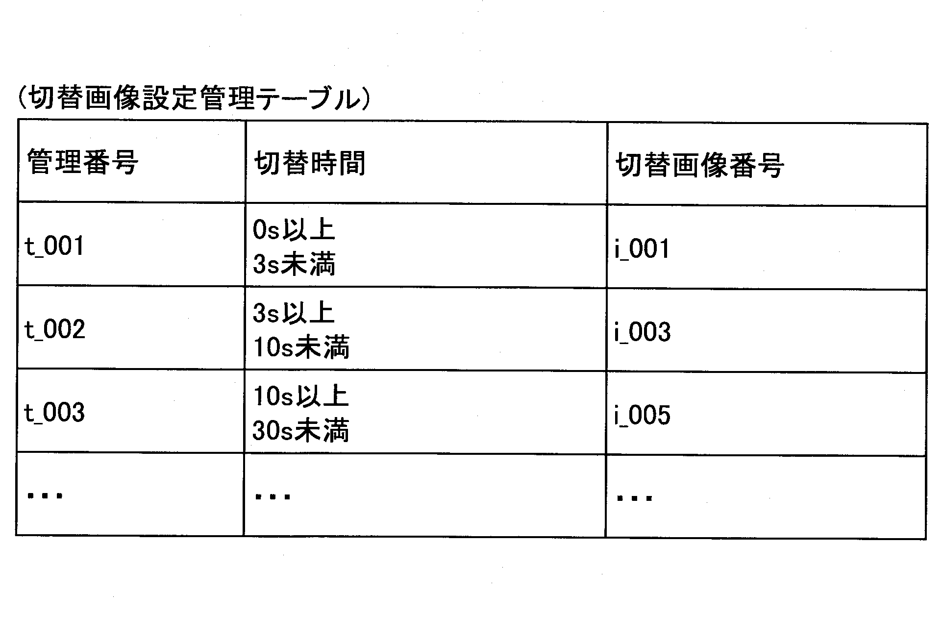
この切替画像設定管理テーブルでは、通信PFの切り替えにかかった時間(切替時間)に切替画像番号が対応づけて管理されている。したがって、本実施例の切替画像決定部21は通信PFの切替時間(測定済みの過去の切替時間)に基づいて切替画像を決定できる。
In this switching image setting management table, switching image numbers are managed in association with the time (switching time) taken to switch the communication PF. Therefore, the switching image determination unit 21 of the present embodiment can determine the switching image based on the switching time of the communication PF (the measured past switching time).
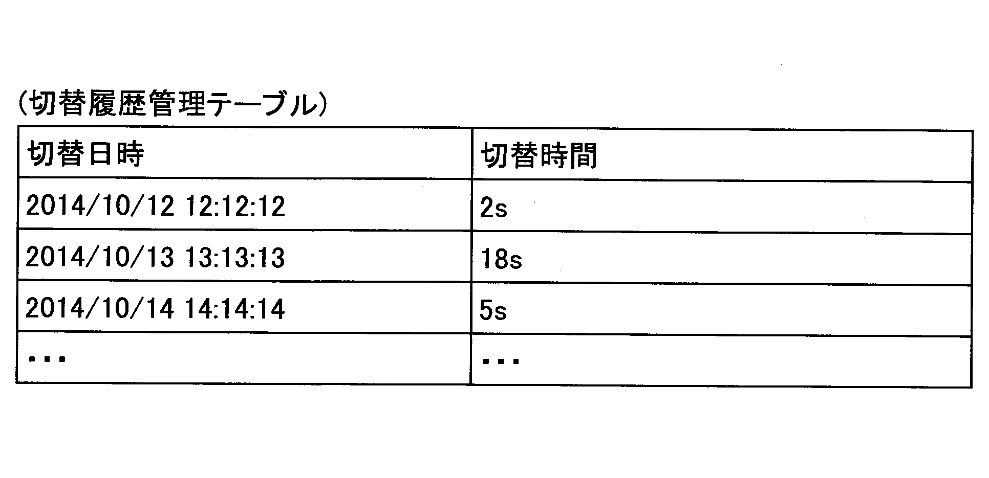
次に、伝送端末10の機能について説明する。図17に示すように、本実施例の伝送端末10は切替履歴処理部22を有している。切替履歴処理部22は、図7に示されているCPU101からの命令によって実現され、通信PFの切り替えに要した切替時間を切替日時と対応づけて切替履歴管理DB1003に記憶させる。切替時間は、例えば、図11のシーケンス図のステップS4の切替開始通知からステップS18の切替終了通知までの時間、又は、図11のシーケンス図のステップS4の切替開始通知からステップS20のセッション確立までの時間、である。この他、例えば、切替画面601を表示してから終了させるまでの時間でもよいし、会議中画面602の表示を終了してから会議中画面602を再表示するまでの時間でもよい。また、伝送管理システム50が測定した切替時間を伝送端末10が取得して切替履歴管理DB1003に登録してもよい。
Next, the function of the transmission terminal 10 will be described. As shown in FIG. 17, the transmission terminal 10 of the present embodiment has a switching history processing unit 22. The switching history processing unit 22 is realized by an instruction from the CPU 101 shown in FIG. 7 and stores the switching time required for switching the communication PF in the switching history management DB 1003 in association with the switching date and time. The switching time is, for example, the time from the switching start notification in step S4 of the sequence diagram of FIG. 11 to the switching end notification in step S18, or the switching start notification in step S4 of the sequence diagram of FIG. It is time for Other than this, for example, the time from the display of the switching screen 601 to the end may be used, or the time from the end of the display of the in-meeting screen 602 to the re-display of the in-meeting screen 602 may be used. The transmission terminal 10 may acquire the switching time measured by the transmission management system 50 and register the switching time in the switching history management DB 1003.
また、本実施例の切替画像決定部21(切替時間推測手段の一例)は、切替履歴管理テーブルに記憶されている切替時間に基づいて通信PFの切替時間を推測する。
Further, the switching image determination unit 21 (an example of the switching time estimation unit) of the present embodiment estimates the switching time of the communication PF based on the switching time stored in the switching history management table.
続いて、図11のステップS6,7における会議中画面602の表示を終了させて伝送端末10が切替画面を表示する処理について説明する。図18は、伝送端末10が会議中画面602の表示を終了させて切替画面601を表示する処理の手順を示すフローチャート図の一例である。
Next, the process of causing the transmission terminal 10 to display the switching screen by ending the display of the in-meeting screen 602 in steps S6 and S7 of FIG. 11 will be described. FIG. 18 is an example of a flowchart showing an example of a process of causing the transmission terminal 10 to end the display of the in-meeting screen 602 and display the switching screen 601.
まず、切替画像決定部21は、通信PFを切り替えるか否かを判定する(S10)。すなわち、伝送管理システム50から切替開始通知が送信されたか否かを判定する。切替開始通知が送信されなければ伝送端末10は何もしない。
First, the switching image determination unit 21 determines whether to switch the communication PF (S10). That is, it is determined whether or not the switching start notification has been transmitted from the transmission management system 50. If the switching start notification is not transmitted, the transmission terminal 10 does nothing.
切替開始通知が送信された場合(S10のYes)、切替画像決定部21は切替履歴管理テーブル及び切替画像設定管理テーブルを参照して切替画像を決定する(S15)。なお、切替開始通知が送信されると切替時間の測定が開始される。切替時間の測定を開始する契機はこれに限られない。
When the switching start notification is transmitted (Yes in S10), the switching image determination unit 21 determines the switching image with reference to the switching history management table and the switching image setting management table (S15). When the switching start notification is transmitted, measurement of the switching time is started. The trigger for starting the measurement of the switching time is not limited to this.
切替画像の決定について説明する。切替履歴管理テーブルでは、例えば以下のような切替時間が参照される。
・日時が一番新しいもの
・全履歴の平均
・過去の所定数の履歴の平均
・過去の1週間分の履歴の平均
・本日と同じ曜日かつ時間帯の過去の履歴の平均
切替画像決定部21は、このように切替履歴管理テーブルを参照して切替時間を推測する。次に、切替画像決定部21は、切替履歴管理テーブルを参照して推測した切替時間に対応づけられている切替画像番号を切替画像設定管理テーブルから読み出す。例えば、切替履歴管理テーブルを参照して推測した切替時間が6sだった場合、切替画像番号としてi_003を読み出す。 The determination of the switching image will be described. In the switching history management table, for example, the following switching time is referred to.
・ The latest date and time ・ Average of all histories ・ Average of a predetermined number of past histories ・ Average of past 1 week's history ・ Average of past history of the same day and time zone as today Thus, the switching time is estimated by referring to the switching history management table. Next, the switchingimage determination unit 21 reads from the switching image setting management table the switching image number associated with the switching time estimated with reference to the switching history management table. For example, when the switching time estimated with reference to the switching history management table is 6s, i_003 is read as the switching image number.
・日時が一番新しいもの
・全履歴の平均
・過去の所定数の履歴の平均
・過去の1週間分の履歴の平均
・本日と同じ曜日かつ時間帯の過去の履歴の平均
切替画像決定部21は、このように切替履歴管理テーブルを参照して切替時間を推測する。次に、切替画像決定部21は、切替履歴管理テーブルを参照して推測した切替時間に対応づけられている切替画像番号を切替画像設定管理テーブルから読み出す。例えば、切替履歴管理テーブルを参照して推測した切替時間が6sだった場合、切替画像番号としてi_003を読み出す。 The determination of the switching image will be described. In the switching history management table, for example, the following switching time is referred to.
・ The latest date and time ・ Average of all histories ・ Average of a predetermined number of past histories ・ Average of past 1 week's history ・ Average of past history of the same day and time zone as today Thus, the switching time is estimated by referring to the switching history management table. Next, the switching
以降のステップS40からS60までの処理は図12と同じである。
The subsequent processes from step S40 to step S60 are the same as in FIG.
次に、通信PFの切り替えが終了すると、切替履歴処理部22は切替時間の測定を終了し、測定した切替時間を切替履歴管理テーブルに日時と共に記憶させる(S65)。ステップS70の処理は図12と同様である。
Next, when the switching of the communication PF is completed, the switching history processing unit 22 ends the measurement of the switching time, and stores the measured switching time in the switching history management table together with the date and time (S65). The process of step S70 is the same as that of FIG.
以上の処理により、通信PFの切り替えにかかった実際の時間をふまえて、伝送端末10が最適な切替画像を使用することができるようになる。
<変形例>
例えば、以下のように、実施例1と本実施例の切替画像設定管理テーブルを組み合わせて用いてもよい。 By the above processing, thetransmission terminal 10 can use the optimum switching image in consideration of the actual time taken to switch the communication PF.
<Modification>
For example, as described below, the switching image setting management tables of the first embodiment and the present embodiment may be used in combination.
<変形例>
例えば、以下のように、実施例1と本実施例の切替画像設定管理テーブルを組み合わせて用いてもよい。 By the above processing, the
<Modification>
For example, as described below, the switching image setting management tables of the first embodiment and the present embodiment may be used in combination.

このような切替画像設定管理テーブルが用いられれば、切替画像決定部21は通信PFの切り替え時のネットワーク帯域及び会議参加拠点数に対応づけられた切替時間のうち、切替履歴管理テーブルから推測した切替時間に適合する切替画像番号を読み出せる。少なくとも現在と同じネットワーク帯域及び会議参加拠点数に対応づけられた切替時間のうち推測された切替時間に対応づけられた切替画像番号を取得するので、より適切な切替画像を選択しやすくなる。
If such a switching image setting management table is used, the switching image determination unit 21 performs switching, which is estimated from the switching history management table, of the switching time associated with the network bandwidth at the time of switching communication PF and the number of conference participants. It is possible to read out the switching image number adapted to the time. Since the switching image number associated with the estimated switching time out of the switching time associated with at least the same network band and the number of conference participants as at the present time is obtained, it becomes easier to select a more appropriate switching image.
また、表12に示すように切替履歴管理テーブルにネットワーク帯域及び会議参加拠点数が登録されていてもよい。
Also, as shown in Table 12, the network band and the number of conference participants may be registered in the switching history management table.

表12の切替履歴管理テーブルのように通信PFの切り替え時の通信状況(ネットワーク帯域及び会議参加拠点数)と同じ通信状況の切替時間が取得できれば、切替画像決定部21は切替時間の予測精度を向上できる。したがって、適切な切替画像を選択しやすくなる。
As in the switching history management table of Table 12, if the switching time of the same communication status as the communication status (network band and the number of conference participants) at the time of switching the communication PF can be acquired, the switching image determination unit 21 It can improve. Therefore, it becomes easy to select an appropriate switching image.
本実施例では会議の画像を切替画像として使用する伝送端末10について説明する。
In this embodiment, a transmission terminal 10 using an image of a conference as a switching image will be described.
図19は本実施例における伝送端末10の機能ブロック図の一例である。なお、伝送管理システム50については実施例1の図9と同じであるため省略した。本実施例において、図9において同一の符号を付した構成要素は同様の機能を果たすので、主に本実施例の主要な構成要素についてのみ説明する場合がある。
FIG. 19 is an example of a functional block diagram of the transmission terminal 10 in the present embodiment. The transmission management system 50 is omitted because it is the same as FIG. 9 of the first embodiment. In the present embodiment, the components given the same reference numerals in FIG. 9 perform the same functions, and therefore, only main components of the present embodiment may be mainly described.
図示するように、本実施例の不揮発性記憶部1000には切替画像設定管理DB1002が構築されていない。また、本実施例の切替画像管理DB1001には会議中にディスプレイ120に表示された会議中画面602の画像が記憶されている。例えば、通信PFの切り替えの直前にディスプレイに表示された会議中画面602の画像である。これにより、通信PFの切り替え中に、通信PFの切り替えが開始される直前の画像を伝送端末10が表示できる。
As illustrated, the switching image setting management DB 1002 is not constructed in the non-volatile storage unit 1000 of this embodiment. Further, the switching image management DB 1001 of the present embodiment stores the image of the in-meeting screen 602 displayed on the display 120 during the meeting. For example, it is an image of the in-meeting screen 602 displayed on the display immediately before switching of the communication PF. Thereby, the transmission terminal 10 can display the image immediately before the switching of the communication PF is started during the switching of the communication PF.
次に、伝送端末10の機能について説明する。図19に示すように、本実施例の伝送端末10は画像取得部23を有している。画像取得部23は、図7に示されているCPU101からの命令によって実現され、ディスプレイ120に表示された画像を取り込む(キャプチャする)。
Next, the function of the transmission terminal 10 will be described. As shown in FIG. 19, the transmission terminal 10 of the present embodiment has an image acquisition unit 23. The image acquisition unit 23 is realized by an instruction from the CPU 101 shown in FIG. 7, and captures (captures) an image displayed on the display 120.
図20を用いて、画像のキャプチャと切替画面601の表示について説明する。図20はディスプレイ120に表示された会議中画面602のキャプチャと切替画面601の表示を模式的に説明する図の一例である。図20の(a)は通信PFの切り替え開始前にディスプレイ120aaに表示される会議中画面602を、図20の(b)は通信PFの切り替え開始後にディスプレイ120aaに表示される切替画面601を、図20の(c)は通信PFの切り替え終了後にディスプレイ120aaに表示される会議中画面602をそれぞれ示す。
Image capture and display of the switching screen 601 will be described with reference to FIG. FIG. 20 is an example of a diagram schematically illustrating the capture of the in-meeting screen 602 displayed on the display 120 and the display of the switching screen 601. (A) of FIG. 20 shows the in-meeting screen 602 displayed on the display 120aa before the start of switching of the communication PF, and (b) of FIG. 20 shows the switching screen 601 displayed on the display 120aa after the start of switching of the communication PF. FIG. 20C shows the in-meeting screen 602 displayed on the display 120aa after the switching of the communication PF is completed.
図20の(a)では、伝送端末10aaは伝送端末10abから送信された画像をディスプレイ120aaに表示している。通信PFの切り替えが開始されると、伝送端末10aaの画像取得部23はディスプレイ120aaに表示されていた会議中画面602を取り込み、会議中画面602の画像を切替画像管理DB1001に記憶させる。
In (a) of FIG. 20, the transmission terminal 10aa displays the image transmitted from the transmission terminal 10ab on the display 120aa. When the switching of the communication PF is started, the image acquisition unit 23 of the transmission terminal 10aa takes in the in-conference screen 602 displayed on the display 120aa, and stores the image of the in-conference screen 602 in the switched image management DB 1001.
図20の(b)に示すように、通信PFの切り替え中、伝送端末10aaは切替画像管理DB1001から取り込んだ会議中画面602の画像を読み出してディスプレイ120aaに表示する。また、図20の(b)に示すように、通信PFの切り替え中、伝送端末10aaは取り込んだ画像を切替画像管理DB1001から読み出してディスプレイ120aaに表示する。また、図20の(c)に示すように、通信PFの切り替えが終了すると、伝送端末10aaは伝送端末10ab、他の伝送端末10acなどから送信された画像を含む会議中画面602をディスプレイ120aaに表示する。
As shown in (b) of FIG. 20, during switching of the communication PF, the transmission terminal 10aa reads the image of the in-conference screen 602 fetched from the switching image management DB 1001 and displays it on the display 120aa. Further, as shown in (b) of FIG. 20, while the communication PF is being switched, the transmission terminal 10aa reads out the captured image from the switching image management DB 1001 and displays it on the display 120aa. Also, as shown in (c) of FIG. 20, when the switching of the communication PF is completed, the transmission terminal 10aa transmits the in-conference screen 602 including the image transmitted from the transmission terminal 10ab, the other transmission terminal 10ac, etc. to the display 120aa. indicate.
したがって、伝送端末10が通信PFを切り替える直前の画像を取り込むことで、通信PFの切り替えを行なっていることをユーザが気づきにくい切替画面601を表示できる。
Therefore, by capturing the image immediately before the transmission terminal 10 switches the communication PF, it is possible to display the switching screen 601 which makes it difficult for the user to notice that the communication PF is switched.
続いて、図11のステップS6,7における会議中画面602の表示を終了させて切替画面601を表示する処理について説明する。図16は、伝送端末10が会議中画面602の表示を終了させて切替画面601を表示する処理の手順を示すフローチャート図の一例である。
Subsequently, a process of ending the display of the in-meeting screen 602 and displaying the switching screen 601 in steps S6 and S7 of FIG. 11 will be described. FIG. 16 is an example of a flowchart showing an example of a process of causing the transmission terminal 10 to end the display of the in-meeting screen 602 and display the switching screen 601.
まず、切替画像決定部21は、通信PFを切り替えるか否かを判定する(S10)。すなわち、伝送管理システム50から切替開始通知が送信されたか否かを判定する。切替開始通知が送信されなければ伝送端末10は何もしない。
First, the switching image determination unit 21 determines whether to switch the communication PF (S10). That is, it is determined whether or not the switching start notification has been transmitted from the transmission management system 50. If the switching start notification is not transmitted, the transmission terminal 10 does nothing.
切替開始通知が送信された場合(S10のYes)、画像取得部23はディスプレイ120に表示している会議中画面602を取り込んで会議中画面602の画像を切替画像管理DB1001に切替画像として記憶させる(S17)。
When the switching start notification is transmitted (Yes in S10), the image acquiring unit 23 loads the in-meeting screen 602 displayed on the display 120 and stores the image of the in-meeting screen 602 in the switching image management DB 1001 as a switching image. (S17).
表示制御部12は、ステップS20で取り込まれた画像を切替画像管理DB1001から読み出す(S40)。以降のステップS50からS70までの処理は図12と同じである。
The display control unit 12 reads the image captured in step S20 from the switching image management DB 1001 (S40). The subsequent processing from step S50 to step S70 is the same as that of FIG.
したがって、本実施例の伝送端末10によれば、ユーザが通信PFの切り替えに気づきにくい切替画面601を表示できる。また、予め切替画像を用意しておく必要がない。
Therefore, according to the transmission terminal 10 of the present embodiment, it is possible to display the switching screen 601 which makes it difficult for the user to notice switching of the communication PF. Moreover, there is no need to prepare a switching image in advance.
なお、画像取得部23は複数の静止画を取り込んでおいてもよい。例えば、画面の表示内容が大きく変化したこと(例えば、参加拠点数が変化した場合、人物から文書の画像に切り替わった場合など)を画像取得部23が検知して、そのたびに画像を取り込む。なお、画像取得部23は静止画の取り込みを定期的に行ってもよい。
The image acquisition unit 23 may capture a plurality of still images. For example, the image acquisition unit 23 detects that the display content of the screen has largely changed (e.g., when the number of participating bases has changed, when switching from a person to an image of a document, etc.), and captures an image each time. The image acquisition unit 23 may periodically capture a still image.
図22、図23、図24は、ディスプレイ120に表示された切替画面601の一例を示す図である。図22、図23、図24はいずれも切替画面601である。表示制御部12は通信PFの切り替え中、切替画像管理DB1001に記憶されている静止画を切替画面601として例えば数秒ずつ表示する。ユーザは会議の内容を反芻することができ、通信PFの切替時間を有効に活用できる。なお、図22、図23、図24の切替画面601では、「通信方式を切り替え中です」などのメッセージを表示することが好ましい。
FIGS. 22, 23 and 24 are diagrams showing an example of the switching screen 601 displayed on the display 120. Each of FIGS. 22, 23, and 24 is a switching screen 601. The display control unit 12 displays still images stored in the switching image management DB 1001 as the switching screen 601, for example, every several seconds while switching the communication PF. The user can refute the contents of the meeting, and can effectively utilize the switching time of the communication PF. In addition, on the switching screen 601 of FIG. 22, FIG. 23, and FIG. 24, it is preferable to display a message such as “switching of communication method”.
また、画像取得部23が取り込む会議中画面602の画像は静止画である必要はなく、動画であってもよい。動画を取り込む場合、例えば最も新しい10~20秒程度の会議中画面602の画像を常に記憶させておき、通信PFの切替中はこの動画を表示する。動画であれば、少なくとも伝送端末10に不具合が生じていないことをユーザが把握できる。
Further, the image of the on-meeting screen 602 captured by the image acquisition unit 23 does not have to be a still image, and may be a moving image. In the case of capturing a moving image, for example, the newest image during the meeting during the latest 10 to 20 seconds is always stored, and this moving image is displayed while switching the communication PF. In the case of a moving image, the user can at least know that the transmission terminal 10 has no problem.
本実施例では通信PFの切り替えフェーズを切替画面601に表示する伝送端末10について説明する。
In this embodiment, the transmission terminal 10 for displaying the switching phase of the communication PF on the switching screen 601 will be described.
なお、本実施例では図9と同じ機能ブロック図を用いるものとして説明する。ただし、本実施例で説明する以下の伝送端末10の機能は実施例1と異なっている。
In this embodiment, the same functional block diagram as that of FIG. 9 is used. However, the function of the following transmission terminal 10 described in the present embodiment is different from that of the first embodiment.
本実施例の切替画像設定管理DB1002には、通信PFの切り替えのフェーズに応じて切替画像を選択するための条件が記憶されている。
The switching image setting management DB 1002 of the present embodiment stores conditions for selecting a switching image in accordance with the switching phase of the communication PF.
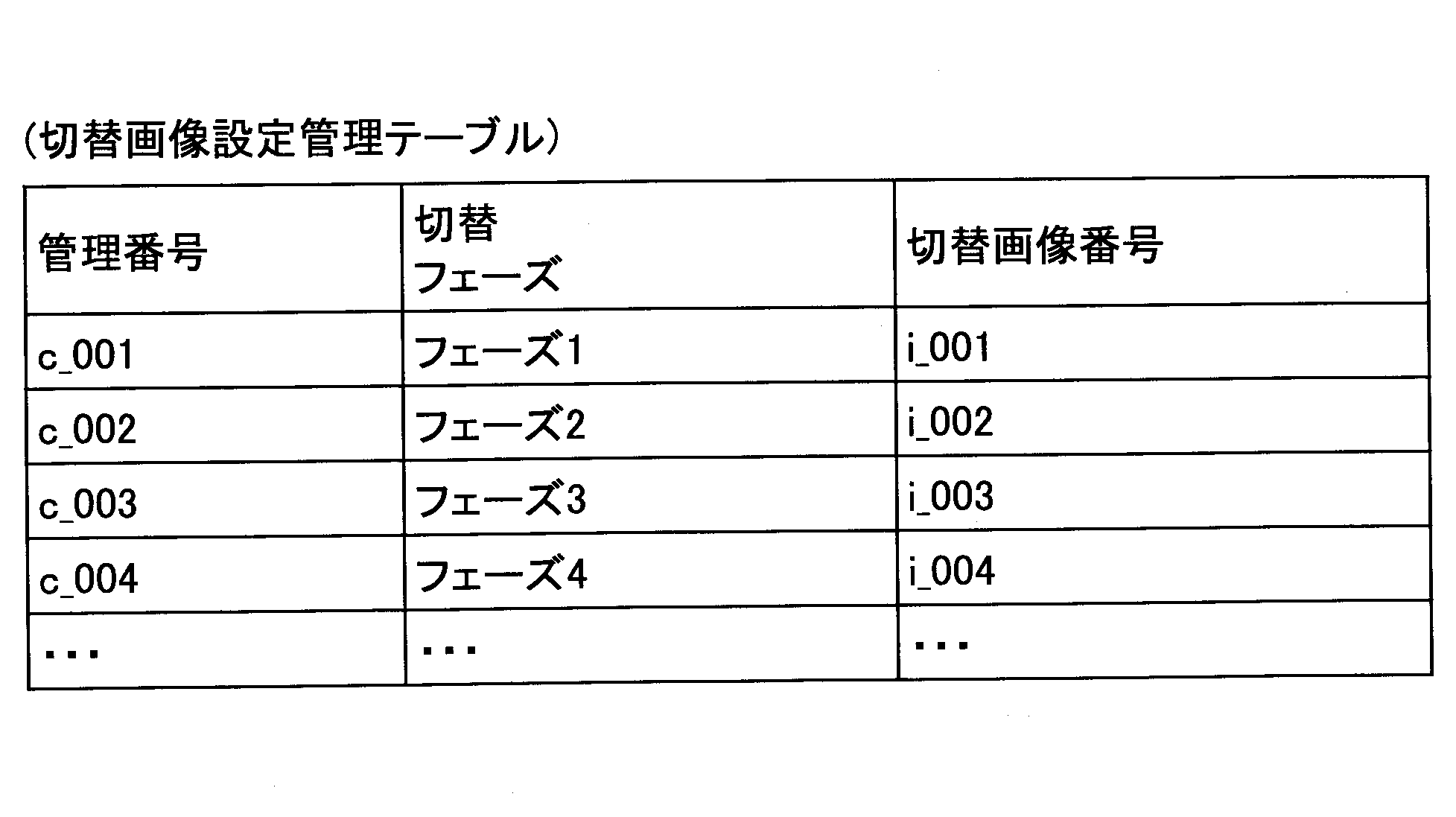
図25、図26は切替画面601の一例を示す図である。図25、図26の切替画面601には、切り替えが進行していることを示すアイコン6012の下にフェーズ1~フェーズ5と表示されている。図25では着色部分が1つのアイコン6012と共にフェーズ1という標示6013が強調表示されている。図26では着色部分が2つのアイコン6012と共にフェーズ1とフェーズ2の標示6014が強調表示されている。このような切替画面601によれば、ユーザは通信PFの切り替え処理の全フェーズのうちどのくらいが進行しているかを把握しやすくなる。
25 and 26 show an example of the switching screen 601. FIG. In the switching screen 601 of FIGS. 25 and 26, phases 1 to 5 are displayed under the icon 6012 indicating that the switching is in progress. In FIG. 25, the indicator 6013 of Phase 1 is highlighted with the colored portion being one icon 6012. In FIG. 26, the colored portions are highlighted with two icons 6012 and the markings 6014 of Phase 1 and Phase 2 are highlighted. According to such a switching screen 601, the user can easily grasp how much of all phases of the switching process of the communication PF is in progress.
本実施例の切替画像決定部21は伝送管理システム50から通信PFの切り替えフェーズに関する情報を取得する(取得手段の一例)。例えば、フェーズ1は全端末へ切り替え開始通知が完了した段階、フェーズ2は伝送管理システム50の切り替えの準備ができた段階、フェーズ3は中継装置30が決まった段階、フェーズ4は全ての伝送端末10が通信PFを切り替えた段階、フェーズ5は全ての伝送端末間でセッションが確立した段階、などが挙げられる。
The switching image determination unit 21 of this embodiment acquires information on the switching phase of the communication PF from the transmission management system 50 (an example of an acquisition unit). For example, phase 1 is a stage at which switching start notification to all terminals is completed, phase 2 is a stage at which the transmission management system 50 is ready for switching, phase 3 is a stage at which the relay apparatus 30 is determined, and phase 4 is all transmission terminals A phase where 10 switches communication PF, a phase 5 is a phase where a session is established between all transmission terminals, and the like.
切替画像決定部21は伝送管理システム50から取得した切り替えフェーズに関する情報に応じて切替画像設定管理テーブルを参照し切替画像を決定する。なお、図25、図26の切替画像のフェーズ1~フェーズ5の標示6013,6014は、フェーズ1~フェーズ5という文字のままでもよいが、伝送管理システム50が行う切り替え処理に応じたものであることが好ましい。適切な標示は、切替画像の作成者が予め切替画像に記述しておく。これにより、ユーザは通信PFの切り替えがどのような段階かを把握しやすくなる。
The switching image determination unit 21 determines the switching image by referring to the switching image setting management table according to the information on the switching phase acquired from the transmission management system 50. The signs 6013 and 6014 of phase 1 to phase 5 of the switching image in FIGS. 25 and 26 may be the letters of phase 1 to phase 5 as they are, but they correspond to the switching process performed by the transmission management system 50. Is preferred. The appropriate label is described in advance in the switch image by the creator of the switch image. This makes it easy for the user to grasp what stage of switching of the communication PF is.
また、切り替えのフェーズとしてセッションが確立した伝送端末10の数を用いてもよい。伝送管理システム50はセッションが確立するごとに伝送端末10に通知する。伝送端末10の切替画像決定部21はセッションが確立した伝送端末10の数に応じて切替画像を決定する。したがって、この場合の切替画面601では、「1つめのセッションが確立しました」という標示、「2つめのセッションが確立しました」という標示などが徐々に増えていく。これらの標示に加え、全拠点数も標示することが好ましい。
Also, the number of transmission terminals 10 for which a session has been established may be used as the switching phase. The transmission management system 50 notifies the transmission terminal 10 each time a session is established. The switching image determination unit 21 of the transmission terminal 10 determines a switching image according to the number of transmission terminals 10 for which a session has been established. Therefore, on the switching screen 601 in this case, the indication "the first session has been established", the indication "the second session has been established", etc. gradually increase. In addition to these indications, it is preferable to indicate the total number of locations.
なお、切替画像にフェーズ1~フェーズ5の標示6013,6014が含まれている必要はなく、実施例1~3の切替画像にフェーズ1~フェーズ5の標示6013,6014を重畳して表示してもよい。すなわち、表示制御部12は伝送管理システム50から通知された切り替えのフェーズを切替画面601に重ねて表示する。
It is not necessary for the switching image to include the indicators 6013 and 6014 of the phase 1 to the phase 5, and the indicators 6013 and 6014 of the phase 1 to the phase 5 are superimposed and displayed on the switching image of the first to third embodiments. It is also good. That is, the display control unit 12 superimposes and displays the switching phase notified from the transmission management system 50 on the switching screen 601.
したがって、本実施例によれば通信PFの切り替え中に伝送端末10が伝送管理システム50と通信することで、切替画面601に切り替えがどの段階まで進んだかを示すフェーズ情報を表示することができる。
<その他の好適な適用例>
本発明を実施するための最良の形態について実施例を用いて説明したが、本発明はこうした実施例に何等限定されるものではなく、本発明の要旨を逸脱しない範囲内において種々の変形及び置換を加えることができる。 Therefore, according to the present embodiment, when thetransmission terminal 10 communicates with the transmission management system 50 while switching the communication PF, it is possible to display on the switching screen 601 phase information indicating to what stage the switching has progressed.
Other Preferred Applications
Although the best mode for carrying out the present invention has been described using examples, the present invention is not limited to these examples in any way, and various modifications and substitutions may be made within the scope of the present invention. Can be added.
<その他の好適な適用例>
本発明を実施するための最良の形態について実施例を用いて説明したが、本発明はこうした実施例に何等限定されるものではなく、本発明の要旨を逸脱しない範囲内において種々の変形及び置換を加えることができる。 Therefore, according to the present embodiment, when the
Other Preferred Applications
Although the best mode for carrying out the present invention has been described using examples, the present invention is not limited to these examples in any way, and various modifications and substitutions may be made within the scope of the present invention. Can be added.
以上の実施例で示した図9などの構成例は、伝送端末10及び伝送管理システム50の処理の理解容易にするために、主な機能に応じて分割したものである。処理単位の分割の仕方や名称によって本願発明が制限されることはない。伝送端末10及び伝送管理システム50の処理は、処理内容に応じてさらに多くの処理単位に分割することもできる。また、1つの処理単位がさらに多くの処理を含むように分割することもできる。
The configuration example of FIG. 9 and the like shown in the above embodiments is divided according to the main functions in order to facilitate understanding of the processing of the transmission terminal 10 and the transmission management system 50. The present invention is not limited by the method and name of division of processing units. The processing of the transmission terminal 10 and the transmission management system 50 can also be divided into more processing units according to the processing content. Also, one processing unit can be divided to include more processes.
また、上記の実施例1~4では、伝送端末10が切替画像管理DB1001、切替画像設定管理DB1002及び切替履歴管理DB1003を有するものとして説明した。しかし、切替画像管理DB1001、切替画像設定管理DB1002及び切替履歴管理DB1003の1つ以上を、伝送管理システム50が有していてもよい。この場合、伝送管理システム50は例えばログインした伝送端末10に切替画像管理DB1001、切替画像設定管理DB1002及び切替履歴管理DB1003を送信する。
Further, in the above-described first to fourth embodiments, the transmission terminal 10 has been described as having the switching image management DB 1001, the switching image setting management DB 1002, and the switching history management DB 1003. However, the transmission management system 50 may have one or more of the switching image management DB 1001, the switching image setting management DB 1002, and the switching history management DB 1003. In this case, the transmission management system 50 transmits, for example, the switching image management DB 1001, the switching image setting management DB 1002, and the switching history management DB 1003 to the transmission terminal 10 that has logged in.
また、上記の実施例1~4では、伝送端末10の切替画像決定部21が切替画像を決定したが、伝送管理システム50が切替画像を決定してもよい。この場合、伝送管理システム50がネットワーク帯域や会議参加拠点数に応じて伝送端末10ごとに切替画像を決定することも可能であり、全ての伝送端末10に対し同じ切替画像を決定することも可能である。この場合も、切替画像管理DB1001は伝送端末10が持っていても伝送管理システム50が持っていてもよく、後者の場合、伝送管理システム50が決定した切替画像を伝送端末10に送信すればよい。
Further, although the switching image determining unit 21 of the transmission terminal 10 determines the switching image in the above-described first to fourth embodiments, the transmission management system 50 may determine the switching image. In this case, the transmission management system 50 can determine the switching image for each transmission terminal 10 according to the network bandwidth and the number of conference participants, and can also determine the same switching image for all the transmission terminals 10 It is. Also in this case, the switching image management DB 1001 may be held by the transmission terminal 10 or the transmission management system 50. In the latter case, the switching image determined by the transmission management system 50 may be transmitted to the transmission terminal 10. .
また、上記の実施例1~4では伝送端末10が切替画面601を表示するとして説明したが、携帯端末20も同様に切替画面601を表示できる。
In the first to fourth embodiments, the transmission terminal 10 displays the switching screen 601. However, the portable terminal 20 can also display the switching screen 601 in the same manner.
また、上記の実施例1~4では、拠点数に応じて通信PFが切り替えられているが、通信PFを切り替える契機はこれに限られない。利用可能帯域の変化、伝送端末10や携帯端末20が移動体通信網を利用しているか否か、全ての伝送端末10が社内LANに接続されているかどうか、又は、全ての伝送端末10が有線接続であるか否かなどに応じて通信PFを切り替えることができる。
Further, in the above-described first to fourth embodiments, the communication PF is switched according to the number of sites, but the opportunity for switching the communication PF is not limited to this. Changes in available bandwidth, whether or not the transmission terminal 10 or the portable terminal 20 uses the mobile communication network, whether all the transmission terminals 10 are connected to the in-house LAN, or all the transmission terminals 10 are wired The communication PF can be switched depending on whether or not the connection is made.
また、上記の実施形態では伝送端末10の一例としてテレビ会議専用端末の場合について説明したが、これに限るものではなく、IP(Internet Protocol)電話やインターネット電話等の電話端末であってもよい。また、スマートフォン、携帯電話機、カーナビゲーション端末、ウェアラブルコンピュータ、カメラ、電子黒板、ゲーム機、又は、通信機能を備えた産業用機器であってもよい。ウェアラブルコンピュータには、腕時計やヘッドマウントディスプレイ等が含まれる。また、産業用機器にはMFP(Multifunction Peripheral/Printer/Product)等のオフィス機器、内視鏡等の医療用機器、耕耘機等の農業用機器などが含まれる。
Further, in the above embodiment, the case of the video conference dedicated terminal has been described as an example of the transmission terminal 10. However, the present invention is not limited to this, and it may be a telephone terminal such as an IP (Internet Protocol) telephone or an Internet telephone. In addition, it may be a smartphone, a mobile phone, a car navigation terminal, a wearable computer, a camera, an electronic blackboard, a game machine, or an industrial device having a communication function. Wearable computers include watches, head mounted displays, and the like. Industrial equipment includes office equipment such as MFP (Multifunction Peripheral / Printer / Product), medical equipment such as an endoscope, and agricultural equipment such as a cultivator.
尚、上述の実施形態は本発明の好適な実施の例ではあるがこれに限定されるものではなく、本発明の要旨を逸脱しない範囲において種々変形実施可能である。
The above-described embodiment is an example of the preferred embodiment of the present invention, but is not limited to this, and various modifications can be made without departing from the scope of the present invention.
例えば、上記実施形態では、PTPシートに包装される錠剤(タブレット)が薬剤である場合について説明したが、これに限定されるものではなく、例えば、食品等であっても良い。
For example, although the case where the tablet (tablet) packaged in the PTP sheet is a medicine has been described in the above embodiment, the present invention is not limited to this, and for example, food or the like may be used.
本国際出願は2015年3月18日に出願された日本国特許出願第2015-055302号に基づく優先権を主張するものであり、日本国特許出願第2015-055302号の全内容をここ本国際出願に援用する。
This international application claims priority based on Japanese Patent Application No. 2015-055302 filed on March 18, 2015, and the entire contents of Japanese Patent Application No. 2015-055302 are incorporated herein by reference. Incorporated in the application.
1 伝送システム
10 伝送端末
18 切替画像決定パラメータ測定部
20 携帯端末
21 切替画像決定部
22 切替履歴処理部
23 画像取得部
30 中継装置
50 伝送管理システム
DESCRIPTION OF
Claims (15)
- 複数の通信プラットフォームの少なくとも1つを用いて他拠点の情報処理装置と通信する情報処理装置であって、
前記他拠点の情報処理装置から送信された送信画像を受信する受信手段と、
前記受信手段が受信した前記送信画像を表示装置に表示する表示手段と、
表示用画像を記憶する画像記憶手段から前記表示用画像を読み出す読出手段と、を有し、
前記通信プラットフォームが切り替えられている間の少なくともある期間において、前記表示手段は前記送信画像を前記読出手段が読み出した前記表示用画像に切り替えて前記表示装置に表示する情報処理装置。 An information processing apparatus that communicates with an information processing apparatus at another site using at least one of a plurality of communication platforms,
A receiving unit configured to receive the transmission image transmitted from the information processing apparatus at the other site;
Display means for displaying the transmission image received by the reception means on a display device;
Reading means for reading the display image from an image storage means for storing a display image;
An information processing apparatus, wherein the display unit switches the transmission image to the display image read by the reading unit and displays the image on the display device at least during a period during which the communication platform is switched. - 前記画像記憶手段には複数の前記表示用画像が記憶されており、
前記他拠点の情報処理装置との通信状況を検出する状況検出手段と、
前記通信状況に対応づけて前記表示用画像の識別情報が登録された画面識別情報記憶手段から、前記状況検出手段が検出した前記通信状況に対応づけられた前記識別情報を取得する画面決定手段と、を有し、
前記読出手段は、前記画面決定手段が取得した前記識別情報の前記表示用画像を前記画像記憶手段から読み出し、
前記通信プラットフォームが切り替えられている間の少なくともある期間において、前記表示手段は前記表示用画像を前記表示装置に表示する請求項1に記載の情報処理装置。 A plurality of the display images are stored in the image storage means,
A condition detection unit that detects a communication condition with the information processing apparatus at the other site;
Screen determination means for acquiring the identification information associated with the communication situation detected by the situation detection means from the screen identification information storage means in which identification information of the display image is registered in association with the communication situation And have
The reading unit reads the display image of the identification information acquired by the screen determination unit from the image storage unit.
The information processing apparatus according to claim 1, wherein the display unit displays the display image on the display device at least during a period during which the communication platform is switched. - 前記状況検出手段は前記通信プラットフォームの切り替えに要する時間に相関する前記通信状況を検出するものであり、
前記画面決定手段は、前記状況検出手段が検出した前記通信状況に基づいて前記表示用画像として動画又は静止画の前記識別情報を画面識別情報記憶手段から取得する請求項2に記載の情報処理装置。 The condition detection means detects the communication condition correlated with the time required to switch the communication platform,
3. The information processing apparatus according to claim 2, wherein the screen determination unit acquires the identification information of a moving image or a still image as the display image from the screen identification information storage unit based on the communication status detected by the status detection unit. . - 前記状況検出手段は前記他拠点の情報処理装置との通信帯域又は拠点数の少なくとも一方を検出するものであり、
前記画面決定手段は、前記状況検出手段が検出した前記通信帯域又は前記拠点数に対応づけられた前記識別情報を画面識別情報記憶手段から取得する請求項3に記載の情報処理装置。 The condition detection means detects at least one of a communication band with the information processing apparatus at the other site and the number of sites,
The information processing apparatus according to claim 3, wherein the screen determination means acquires the identification information associated with the communication band detected by the situation detection means or the number of bases from the screen identification information storage means. - 前記画像記憶手段には複数の前記表示用画像が記憶されており、
前記通信プラットフォームの切り替えに要した切替時間を切替時間記憶手段に記録する記録手段と、
前記切替時間記憶手段に記憶されている過去の前記切替時間に基づいて前記通信プラットフォームの切り替えに要する前記切替時間を推測する切替時間推測手段と、
前記切替時間に対応づけて前記表示用画像の識別情報が登録された画面識別情報記憶手段から、前記切替時間推測手段が推測した前記切替時間に対応づけられた前記識別情報を取得する画面決定手段と、を有し、
前記読出手段は、前記画面決定手段が取得した前記識別情報の前記表示用画像を前記画像記憶手段から読み出し、
前記通信プラットフォームが切り替えられている間の少なくともある期間において、前記表示手段は前記表示用画像を前記表示装置に表示する請求項1に記載の情報処理装置。 A plurality of the display images are stored in the image storage means,
Recording means for recording switching time required for switching the communication platform in switching time storage means;
Switching time estimation means for estimating the switching time required for switching of the communication platform based on the past switching time stored in the switching time storage means;
Screen determination means for acquiring the identification information associated with the switching time estimated by the switching time estimation means from the screen identification information storage means in which identification information of the display image is registered in association with the switching time And
The reading unit reads the display image of the identification information acquired by the screen determination unit from the image storage unit.
The information processing apparatus according to claim 1, wherein the display unit displays the display image on the display device at least during a period during which the communication platform is switched. - 前記他拠点の情報処理装置との通信状況を検出する状況検出手段を有し、
前記画面識別情報記憶手段には、前記切替時間及び前記通信状況に対応づけて前記表示用画像の前記識別情報が登録されており、
前記画面決定手段は、前記画面識別情報記憶手段から、前記切替時間推測手段が推測した前記切替時間及び前記状況検出手段が検出した前記通信状況に対応づけられた前記識別情報を取得する請求項5に記載の情報処理装置。 It has situation detection means for detecting the communication situation with the information processing apparatus at the other site,
In the screen identification information storage means, the identification information of the display image is registered in association with the switching time and the communication state,
The screen determination means acquires, from the screen identification information storage means, the switching time estimated by the switching time estimation means and the identification information associated with the communication status detected by the situation detection means. The information processing apparatus according to claim 1. - 前記他拠点の情報処理装置との通信状況を検出する状況検出手段を有し、
前記記録手段は、前記通信プラットフォームの切り替えに要した切替時間を前記状況検出手段が検出した前記通信状況に対応づけて前記切替時間記憶手段に記録し、
前記切替時間推測手段は、前記切替時間記憶手段において前記状況検出手段が検出した前記通信状況に対応づけられている前記切替時間に基づいて前記通信プラットフォームの切り替えに要する前記切替時間を推測し、
前記画面決定手段は、前記画面識別情報記憶手段から前記切替時間推測手段が推測した前記切替時間に対応づけられた前記識別情報を取得する請求項5に記載の情報処理装置。 It has situation detection means for detecting the communication situation with the information processing apparatus at the other site,
The recording unit associates the switching time required for switching the communication platform with the communication status detected by the status detecting unit and records the switching status in the switching time storage unit.
The switching time estimation unit estimates the switching time required to switch the communication platform based on the switching time associated with the communication status detected by the status detection unit in the switching time storage unit.
The information processing apparatus according to claim 5, wherein the screen determination unit acquires the identification information associated with the switching time estimated by the switching time estimation unit from the screen identification information storage unit. - 前記表示用画像は前記通信プラットフォームの切り替え中であることを示す情報が含まれる請求項1~7いずれか1項に記載の情報処理装置。 The information processing apparatus according to any one of claims 1 to 7, wherein the display image includes information indicating that the communication platform is being switched.
- 前記表示装置に表示された前記送信画像を取り込む取り込み手段を有し、
前記通信プラットフォームが切り替えられている間の少なくともある期間において、前記表示手段は、前記取り込み手段が取り込んだ前記送信画像を前記表示装置に表示する請求項1に記載の情報処理装置。 And a capturing unit configured to capture the transmission image displayed on the display device.
The information processing apparatus according to claim 1, wherein the display unit displays the transmission image captured by the capture unit on the display device at least during a period during which the communication platform is switched. - 前記通信プラットフォームの切り替えが開始される前に、前記取り込み手段は複数の前記送信画像を取り込んでおき、
前記通信プラットフォームが切り替えられている間の少なくともある期間において、前記表示手段は、前記取り込み手段が取り込んだ複数の前記送信画像を切り替えて前記表示装置に表示する請求項9に記載の情報処理装置。 Before the switching of the communication platform is started, the capturing unit captures a plurality of the transmission images,
The information processing apparatus according to claim 9, wherein the display unit switches the plurality of transmission images captured by the capture unit and displays the image on the display device at least during a period during which the communication platform is switched. - 前記通信プラットフォームを切り替える装置から前記通信プラットフォームの切り替えのフェーズ情報を取得する取得手段を有し、
前記表示手段は、前記取得手段が取得した前記フェーズ情報を前記表示用画像と共に前記表示装置に表示する請求項1~10いずれか1項に記載の情報処理装置。 It has acquisition means for acquiring phase information of switching of the communication platform from an apparatus that switches the communication platform,
The information processing apparatus according to any one of claims 1 to 10, wherein the display means displays the phase information acquired by the acquisition means together with the display image on the display device. - 前記複数の通信プラットフォームの少なくとも1つは映像データの送信方法が異なる請求項1~11いずれか1項に記載の情報処理装置。 The information processing apparatus according to any one of claims 1 to 11, wherein at least one of the plurality of communication platforms has a different method of transmitting video data.
- 複数の通信プラットフォームの少なくとも1つを用いて他拠点の情報処理装置と通信する情報処理装置によって行われる画面表示方法であって、
受信手段が、前記他拠点の情報処理装置から送信された送信画像を受信するステップと、
表示手段が、前記受信手段が受信した前記送信画像を表示装置に表示するステップと、
読出手段が、表示用画像を記憶する画像記憶手段から前記表示用画像を読み出すステップと、
前記通信プラットフォームが切り替えられている間の少なくともある期間において、前記表示手段が、前記送信画像を前記読出手段が読み出した前記表示用画像に切り替えて前記表示装置に表示するステップと、を有する画面表示方法。 A screen display method performed by an information processing apparatus communicating with an information processing apparatus at another site using at least one of a plurality of communication platforms,
Receiving means for receiving a transmission image transmitted from the information processing apparatus at the other site;
Displaying the transmission image received by the receiving means on a display device;
Reading the display image from the image storage unit storing the display image;
Displaying the display image on the display device by switching the transmission image to the display image read by the reading unit, at least during a period during which the communication platform is switched. Method. - 複数の通信プラットフォームの少なくとも1つを用いて他拠点の情報処理装置と通信する情報処理装置に、
前記他拠点の情報処理装置から送信された送信画像を受信する受信ステップと、
前記受信ステップにより受信された前記送信画像を表示装置に表示する表示ステップと、
表示用画像を記憶する画像記憶手段から前記表示用画像を読み出す読出ステップと、
前記通信プラットフォームが切り替えられている間の少なくともある期間において、前記送信画像を前記読出ステップにより読み出された前記表示用画像に切り替えて前記表示装置に表示するステップと、
を実行させるためのプログラム。 An information processing apparatus that communicates with an information processing apparatus at another site using at least one of a plurality of communication platforms,
A receiving step of receiving a transmission image transmitted from the information processing apparatus at the other site;
Displaying the transmitted image received by the receiving step on a display device;
Reading out the image for display from the image storage means for storing the image for display;
Switching the transmission image to the display image read out by the reading step for at least a period of time while the communication platform is switched, and displaying the display image on the display device;
A program to run a program. - 複数の通信プラットフォームの少なくとも1つを用いて他拠点の情報処理装置と通信する情報処理装置と、前記通信プラットフォームを切り替える情報処理装置とを有する伝送システムであって、
前記他拠点の情報処理装置から送信された送信画像を受信する受信手段と、
前記受信手段が受信した前記送信画像を表示装置に表示する表示手段と、
表示用画像を記憶する画像記憶手段から前記表示用画像を読み出す読出手段と、を有し、
前記通信プラットフォームが切り替えられている間の少なくともある期間において、前記表示手段は前記送信画像を前記読出手段が読み出した前記表示用画像に切り替えて前記表示装置に表示する伝送システム。
A transmission system comprising: an information processing apparatus that communicates with an information processing apparatus at another site using at least one of a plurality of communication platforms; and an information processing apparatus that switches the communication platform,
A receiving unit configured to receive the transmission image transmitted from the information processing apparatus at the other site;
Display means for displaying the transmission image received by the reception means on a display device;
Reading means for reading the display image from an image storage means for storing a display image;
A transmission system, wherein the display unit switches the transmission image to the display image read by the reading unit and displays the image on the display device at least during a period during which the communication platform is switched.
Priority Applications (4)
| Application Number | Priority Date | Filing Date | Title |
|---|---|---|---|
| CN201680015510.3A CN107431781B (en) | 2015-03-18 | 2016-03-01 | Information processing apparatus, screen switching method, non-transitory recording medium, and transmission system |
| JP2017506186A JP6399204B2 (en) | 2015-03-18 | 2016-03-01 | Information processing apparatus, screen switching method, program, transmission system |
| EP16764685.0A EP3273683A4 (en) | 2015-03-18 | 2016-03-01 | Information processing device, screen switching method, program, and transmission system |
| US15/703,707 US10177864B2 (en) | 2015-03-18 | 2017-09-13 | Information processing apparatus, screen displaying method, and transmission system |
Applications Claiming Priority (2)
| Application Number | Priority Date | Filing Date | Title |
|---|---|---|---|
| JP2015-055302 | 2015-03-18 | ||
| JP2015055302 | 2015-03-18 |
Related Child Applications (1)
| Application Number | Title | Priority Date | Filing Date |
|---|---|---|---|
| US15/703,707 Continuation US10177864B2 (en) | 2015-03-18 | 2017-09-13 | Information processing apparatus, screen displaying method, and transmission system |
Publications (1)
| Publication Number | Publication Date |
|---|---|
| WO2016147855A1 true WO2016147855A1 (en) | 2016-09-22 |
Family
ID=56918904
Family Applications (1)
| Application Number | Title | Priority Date | Filing Date |
|---|---|---|---|
| PCT/JP2016/056292 WO2016147855A1 (en) | 2015-03-18 | 2016-03-01 | Information processing device, screen switching method, program, and transmission system |
Country Status (5)
| Country | Link |
|---|---|
| US (1) | US10177864B2 (en) |
| EP (1) | EP3273683A4 (en) |
| JP (1) | JP6399204B2 (en) |
| CN (1) | CN107431781B (en) |
| WO (1) | WO2016147855A1 (en) |
Cited By (1)
| Publication number | Priority date | Publication date | Assignee | Title |
|---|---|---|---|---|
| JP7555837B2 (en) | 2021-01-28 | 2024-09-25 | 株式会社日立国際電気 | Camera System |
Families Citing this family (8)
| Publication number | Priority date | Publication date | Assignee | Title |
|---|---|---|---|---|
| CN106161179B (en) * | 2015-03-26 | 2019-12-20 | 中兴通讯股份有限公司 | Media processing method and device based on real-time communication of webpage |
| KR102362899B1 (en) * | 2017-10-31 | 2022-02-11 | 삼성에스디에스 주식회사 | Conference system and method for controlling bandwidth thereof |
| CN108446088B (en) * | 2018-04-18 | 2024-09-10 | 广州视源电子科技股份有限公司 | Terminal and screen throwing system |
| US11061641B2 (en) | 2019-02-28 | 2021-07-13 | Ricoh Company, Ltd. | Screen sharing system, and information processing apparatus |
| CN111030921B (en) * | 2019-12-17 | 2023-02-10 | 杭州涂鸦信息技术有限公司 | Multi-window communication method and system based on webpage instant messaging |
| JP2022029341A (en) | 2020-08-04 | 2022-02-17 | 株式会社リコー | Communication system, communication terminal, communication method, and program |
| CN114567619B (en) * | 2020-11-27 | 2023-01-17 | 荣耀终端有限公司 | Equipment recommendation method and electronic equipment |
| JP2022150661A (en) * | 2021-03-26 | 2022-10-07 | ブラザー工業株式会社 | Communication device, computer program for communication device, and, method executed by communication device |
Citations (1)
| Publication number | Priority date | Publication date | Assignee | Title |
|---|---|---|---|---|
| JP2004328402A (en) * | 2003-04-24 | 2004-11-18 | Sony Corp | Site state monitor method and site state monitor device |
Family Cites Families (11)
| Publication number | Priority date | Publication date | Assignee | Title |
|---|---|---|---|---|
| JP2769195B2 (en) * | 1989-07-14 | 1998-06-25 | 日本電信電話株式会社 | Multipoint video conference still image display system |
| JPH11261906A (en) * | 1998-01-12 | 1999-09-24 | Sony Corp | Television broadcast receiver, television broadcast reception method and television broadcast method |
| JP3895982B2 (en) * | 2001-12-20 | 2007-03-22 | 株式会社東芝 | Mobile communication terminal |
| JP4813096B2 (en) * | 2004-07-06 | 2011-11-09 | パナソニック株式会社 | Receiving device, receiving method, program, and semiconductor device |
| JP4332673B2 (en) * | 2005-03-10 | 2009-09-16 | 株式会社カシオ日立モバイルコミュニケーションズ | Communication terminal and radio wave intensity display method |
| JP2007036981A (en) | 2005-07-29 | 2007-02-08 | Canon Inc | Camera with communication function |
| JP2008090651A (en) * | 2006-10-03 | 2008-04-17 | Nagaoka Univ Of Technology | Network system |
| WO2008149647A1 (en) * | 2007-05-30 | 2008-12-11 | Sony Corporation | Broadcast receiver and reproducing method |
| JP5332600B2 (en) * | 2008-12-25 | 2013-11-06 | ソニー株式会社 | Information processing apparatus, communication control method, program, and information processing system |
| JP2010204986A (en) * | 2009-03-04 | 2010-09-16 | Sony Corp | Communication device, communication method, and program |
| EP2797349B1 (en) * | 2009-11-30 | 2018-09-26 | Sun Patent Trust | Communication device with several antennas, communication method, and position determination method |
-
2016
- 2016-03-01 WO PCT/JP2016/056292 patent/WO2016147855A1/en active Application Filing
- 2016-03-01 JP JP2017506186A patent/JP6399204B2/en not_active Expired - Fee Related
- 2016-03-01 EP EP16764685.0A patent/EP3273683A4/en not_active Withdrawn
- 2016-03-01 CN CN201680015510.3A patent/CN107431781B/en not_active Expired - Fee Related
-
2017
- 2017-09-13 US US15/703,707 patent/US10177864B2/en active Active
Patent Citations (1)
| Publication number | Priority date | Publication date | Assignee | Title |
|---|---|---|---|---|
| JP2004328402A (en) * | 2003-04-24 | 2004-11-18 | Sony Corp | Site state monitor method and site state monitor device |
Cited By (1)
| Publication number | Priority date | Publication date | Assignee | Title |
|---|---|---|---|---|
| JP7555837B2 (en) | 2021-01-28 | 2024-09-25 | 株式会社日立国際電気 | Camera System |
Also Published As
| Publication number | Publication date |
|---|---|
| CN107431781B (en) | 2020-05-12 |
| EP3273683A4 (en) | 2018-07-04 |
| EP3273683A1 (en) | 2018-01-24 |
| US10177864B2 (en) | 2019-01-08 |
| CN107431781A (en) | 2017-12-01 |
| JP6399204B2 (en) | 2018-10-03 |
| US20180013503A1 (en) | 2018-01-11 |
| JPWO2016147855A1 (en) | 2018-02-08 |
Similar Documents
| Publication | Publication Date | Title |
|---|---|---|
| JP6399204B2 (en) | Information processing apparatus, screen switching method, program, transmission system | |
| KR101257594B1 (en) | Transmission management system, transmission system, computer-readable recording medium, program providing system, and maintenance system | |
| JP5953689B2 (en) | Transmission management system, transmission system, and program for transmission management system | |
| JP6269610B2 (en) | Information processing apparatus, image display method, communication system, program | |
| JP5811334B2 (en) | Transmission management system, transmission management method, program, and transmission system | |
| JP5655499B2 (en) | Transmission management system, transmission system, transmission management program, program providing system, and maintenance system | |
| JP6634686B2 (en) | Information processing apparatus, program, communication platform determination method, transmission system | |
| JP2012195926A (en) | Transmission management apparatus | |
| JP5983792B2 (en) | Transmission system and transmission method | |
| JP2019110603A (en) | Transmission terminal, program, transmission method, and transmission system | |
| JP2012109935A (en) | Transmission management system, transmission system, transmission management method, transmission management program, program provision system, and maintenance system | |
| JP2014082573A (en) | Transmission terminal transmission method and program | |
| JP2017028658A (en) | Information processing device, image display method, communication system and program | |
| JP2017073794A (en) | Transmission system, transmission method by transmission system, transmission terminal, transmission terminal control method, transmission terminal control program, transmission management device, management method by transmission management device and transmission management program | |
| US9955118B2 (en) | Information processing apparatus, communication system, and recording medium | |
| JP2014072703A (en) | Transmission management system, transmission system, transmission management method, and program | |
| JP6327338B2 (en) | Destination terminal, transmission system, relay device selection method, and recording medium | |
| JP2017028660A (en) | Information processing device, image display method, communication system and program | |
| JP6531391B2 (en) | Transmission management system, transmission system, relay device control method, and program | |
| JP6515436B2 (en) | Transmission system, transmission terminal, and program | |
| JP2017092647A (en) | Information processing system, information processing apparatus, information processing method, and program | |
| JP2018037806A (en) | Transmission management system, transmission management method, and program | |
| JP2016100742A (en) | Transmission management system, transmission system, relay device control method and program | |
| JP2016076772A (en) | Relay device, communication management system, relay method, and program | |
| JP2017216701A (en) | Transmission terminal, transmission method, and program |
Legal Events
| Date | Code | Title | Description |
|---|---|---|---|
| 121 | Ep: the epo has been informed by wipo that ep was designated in this application |
Ref document number: 16764685 Country of ref document: EP Kind code of ref document: A1 |
|
| ENP | Entry into the national phase |
Ref document number: 2017506186 Country of ref document: JP Kind code of ref document: A |
|
| REEP | Request for entry into the european phase |
Ref document number: 2016764685 Country of ref document: EP |
|
| NENP | Non-entry into the national phase |
Ref country code: DE |