WO2016147395A1 - 成形体の切断装置および製造装置 - Google Patents
成形体の切断装置および製造装置 Download PDFInfo
- Publication number
- WO2016147395A1 WO2016147395A1 PCT/JP2015/058305 JP2015058305W WO2016147395A1 WO 2016147395 A1 WO2016147395 A1 WO 2016147395A1 JP 2015058305 W JP2015058305 W JP 2015058305W WO 2016147395 A1 WO2016147395 A1 WO 2016147395A1
- Authority
- WO
- WIPO (PCT)
- Prior art keywords
- vibration
- molded body
- cutting
- cutting wire
- receiving portion
- Prior art date
- Legal status (The legal status is an assumption and is not a legal conclusion. Google has not performed a legal analysis and makes no representation as to the accuracy of the status listed.)
- Ceased
Links
Images




Classifications
-
- A—HUMAN NECESSITIES
- A24—TOBACCO; CIGARS; CIGARETTES; SIMULATED SMOKING DEVICES; SMOKERS' REQUISITES
- A24B—MANUFACTURE OR PREPARATION OF TOBACCO FOR SMOKING OR CHEWING; TOBACCO; SNUFF
- A24B13/00—Tobacco for pipes, for cigars, e.g. cigar inserts, or for cigarettes; Chewing tobacco; Snuff
Definitions
- the present invention relates to a cutting device for cutting a formed body having a honeycomb structure used for a smoking article into a predetermined length. Furthermore, this invention relates to the manufacturing apparatus provided with the cutting device which cut
- Solid tobacco blended with tobacco raw materials pulverized into powder is obtained by cutting a rod-shaped tobacco molded product into a desired length.
- the tobacco molded body is formed, for example, by extruding a tobacco mixture containing a tobacco raw material and water from an extruder.
- the tobacco molded body extruded from the extruder has a honeycomb structure in which a plurality of air passages partitioned from each other are provided in a region surrounded by an outer peripheral wall.
- Patent Document 1 discloses an example of an apparatus for cutting a formed body having a honeycomb structure.
- the cutting device disclosed in Patent Document 1 includes a frame in which a wire for cutting a molded body is fixed in a straight line, and a vibration generating unit that vibrates the wire as main elements.
- the frame has a base part and a frame main body part coupled to the base part via a rotating shaft and a plurality of elastic bodies.
- the base portion is slidably held in a groove provided in the guide, and is movable in a direction intersecting the molded body.
- the frame main body swings in the longitudinal direction of the wire with the rotation axis as a fulcrum, and the swing range of the frame main body is defined by the elastic body being bent and deformed.
- the vibration generating unit is an element that applies vibration to the frame main body at a position eccentric from the rotation axis, and has an eccentric disk driven by a motor.
- the eccentric disk has a center of gravity at a position eccentric from the rotation axis of the motor, and the center of gravity revolves around the rotation axis, so that vibration is applied to the frame main body.
- the frame main body When the vibration is applied from the vibration generating unit to the frame main body, the frame main body reciprocates within a predetermined range along the longitudinal direction of the wire with the rotation axis as the center. As a result, the wire fixed to the frame main body vibrates along the length direction.
- the molded body can be cut to a desired length by pressing the vibrating wire against the molded body and moving it in the radial direction of the molded body together with the base portion.
- the vibration generating unit is configured by swinging the frame main body unit coupled to the base unit around the rotation axis within a range in which the plurality of elastic bodies bend and deform.
- produced into the vibration along the longitudinal direction of a wire is required.
- a dedicated guide for slidably supporting the base unit to which the frame main body is coupled is required.
- An object of the present invention is to obtain a molded body cutting apparatus capable of vibrating a cutting wire with a simple configuration and a manufacturing apparatus including the cutting apparatus.
- a cutting apparatus comprises: A vibration source that emits vibration; A cutting wire in contact with a rod-shaped molded body used for a smoking part; A pair of a vibration receiving portion provided with the vibration generating source and a pair of members extending from the vibration receiving portion along a direction intersecting the vibration receiving portion, facing each other with a space therebetween and spanning the cutting wire And a vibration transmission portion including the arm portion.
- the vibration transmitting unit transmits the vibration generated by the vibration generating unit from the vibration receiving unit to the arm unit, and bends the arm unit in the longitudinal direction of the cutting wire, thereby generating the vibration generating unit.
- the vibration is converted into a reciprocating motion of the arm portion along the longitudinal direction of the cutting wire and transmitted to the cutting wire.
- the vibration transmitting portion described in the first aspect is formed of a material capable of elastic deformation.
- the cutting wire is made of a stretchable material.
- the vibration transmitting portion has a joint portion between the vibration receiving portion and the arm portion. It is a monolithic structure that does not have.
- the vibration receiving portion has a shape extending along the cutting wire, and the vibration The vibration generating source is provided at an intermediate portion along the longitudinal direction of the receiving portion.
- the molded body has a honeycomb structure provided with a plurality of air passages partitioned from each other.
- the said cutting wire is formed with the wire thinner than the shape of the cross section along the radial direction of the said ventilation path.
- the cutting wire is vibrated at a frequency higher than the commercial frequency.
- the support portion that supports the vibration receiving portion of the vibration transmitting portion, the vibration receiving portion, and the And a pair of fulcrum portions spaced from each other with a portion receiving vibration from the vibration generating source as a boundary among the vibration receiving portions.
- the vibration receiving portion is configured to reciprocate in a direction where at least a portion straddling between the fulcrum portions intersects a straight line connecting the fulcrum portions when receiving vibration generated by the vibration generating source. Yes.
- the fulcrum part described in the eighth aspect is formed of a rubber-like elastic body.
- the vibration receiving portion and the support portion at least between the fulcrum portions of the vibration receiving portion.
- a gap is provided to allow the vibration of the portion to straddle.
- the molded body is formed of a tobacco mixture.
- a manufacturing apparatus includes: An extruder for extruding a rod-shaped molded body used for smoking articles; A transport device for receiving and transporting the molded body extruded from the extruder; A cutting device that cuts the molded body that is transported by the transport device into a predetermined length at a cutting position that is defined on the downstream side along the transport direction of the transport device.
- the cutting device is A vibration source that emits vibration; A cutting wire in contact with the molded body; A pair of a vibration receiving portion provided with the vibration generating source and a pair of members extending from the vibration receiving portion along a direction intersecting the vibration receiving portion, facing each other with a space therebetween and spanning the cutting wire And a vibration transmission portion including the arm portion.
- the vibration transmitting unit transmits the vibration generated by the vibration generating unit from the vibration receiving unit to the arm unit, and bends the arm unit in the longitudinal direction of the cutting wire, thereby generating the vibration generating unit.
- the vibration is converted into a reciprocating motion of the arm portion along the longitudinal direction of the cutting wire and transmitted to the cutting wire.
- the conveying device described in the twelfth aspect conveys the molded body extruded from the extruder by the first conveyor and the first conveyor.
- the measuring device for measuring the outer diameter of the molded body conveyed by the first conveyor, and the molding measured by the measuring device.
- a control device that controls the transport speed of the second conveyor based on the outer diameter of the body.
- the control device is configured to increase the tensile force applied to the molded body pushed out from the extruder when the outer diameter of the molded body measured by the measuring device exceeds a maximum allowable value.
- the vibration transmission path from the vibration generating source to the cutting wire can be simplified, and the mechanical operation for vibrating the cutting wire can be simplified. Therefore, it is possible to reduce the cost of the cutting device by reducing the number of parts, and to reduce the size of the cutting device.
- FIG. 1 is a perspective view showing a state in which the solid cigarette according to the first embodiment of the present invention is set in a smoking tool.
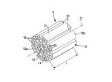
- FIG. 2 is a perspective view of the solid cigarette according to the first embodiment of the present invention.
- FIG. 3 is a front view of the solid cigarette according to the first embodiment of the present invention.
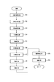
- FIG. 4 is a flowchart showing a process of manufacturing the solid tobacco according to the first embodiment of the present invention.
- FIG. 5 is a side view showing an outline of a production apparatus for producing the solid tobacco according to the first embodiment of the present invention.
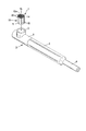
- FIG. 6 is a front view of a cutting device for cutting a rod-shaped tobacco molded body extruded from an extruder into a predetermined length in the first embodiment of the present invention.
- FIG. 7 is a side view of the cutting device viewed from the direction of the arrow F7 in FIG.
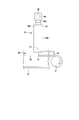
- FIG. 8 is a front view of a cutting device according to the second embodiment of the present invention.
- FIG. 1 discloses a smoke tube-shaped smoking tool 2 in which a solid cigarette 1 is set.
- the solid tobacco 1 is an example of a smoking article.
- the smoking tool 2 is composed mainly of a fire plate 3 into which the solid cigarette 1 is inserted, a mouthpiece 4 which a smoker holds in his mouth, and a metal pipe portion 5 which connects between the fire plate 3 and the mouthpiece 4.
- a portion of the tube portion 5 that is grasped by a smoker by hand is covered with a cover 6 made of silicon.
- the solid cigarette 1 inserted in the pan 3 is burned when ignited.
- a flavor component is released.
- the released flavor component is supplied to the smoker from the tube part 5 through the mouthpiece 4.
- the solid tobacco 1 according to the present embodiment is formed in a cylindrical shape having a central axis O1.
- the solid tobacco 1 includes a honeycomb structure 10 including at least a tobacco raw material.
- tobacco raw materials of the raw material types adopted in general tobacco products such as Orient, yellow and burre can be applied.
- the honeycomb structure 10 has an outer peripheral wall 11, a first end face 12a, and a second end face 12b.
- the outer peripheral wall 11 surrounds the central axis O1 of the solid tobacco 1 coaxially.
- the first end surface 12 a is located at one end along the axial direction of the outer peripheral wall 11.
- the second end surface 12 b is located at the other end along the axial direction of the outer peripheral wall 11.
- the first end surface 12a and the second end surface 12b extend in a direction orthogonal to the central axis O1.
- a plurality of slits 13 are formed in the outer peripheral wall 11.
- the slits 13 extend in the axial direction of the central axis O ⁇ b> 1 and are arranged at intervals in the circumferential direction of the outer peripheral wall 11.
- the slit 13 is opened to the first end surface 12a and the second end surface 12b.
- the honeycomb structure 10 has lattice-shaped partition walls 14 and a center hole 15 in a region surrounded by the outer peripheral wall 11.
- the partition walls 14 define a plurality of ventilation paths 16 inside the honeycomb structure 10.
- the ventilation path 16 extends in the axial direction of the central axis O ⁇ b> 1 and is partitioned from each other by the partition wall 14. Further, the air passage 16 is opened in the first end surface 12 a and the second end surface 12 b of the honeycomb structure 10.
- Various forms such as a square lattice, a hexagonal lattice, and a triangular lattice can be applied as the lattice form, and the form of the lattice is not particularly limited.
- the center hole 15 is formed coaxially with the center axis O1 of the honeycomb structure 10.
- the center hole 15 is surrounded by the air passage 16 and is opened to the first end surface 12 a and the second end surface 12 b of the honeycomb structure 10.
- the total length L of the solid tobacco 1 along the central axis O1 is, for example, 7 mm, and the diameter D of the solid tobacco 1 is, for example, 6.1 mm.
- the thickness t1 of the outer peripheral wall 11 of the honeycomb structure 10 is preferably in the range of 0.1 to 0.5 mm.
- the thickness t2 of the partition wall 14 of the honeycomb structure 10 is preferably in the range of 0.1 to 0.5 mm.
- FIG. 4 is a flowchart schematically showing a manufacturing process of the solid tobacco 1 according to the present embodiment.
- a plurality of tobacco raw material species such as an Orient species, a yellow species and a burre species are pulverized into powder.
- the pulverized tobacco raw material seeds are classified into a plurality of groups according to the size of the particles.
- the pulverized tobacco raw material species, carboxymethyl cellulose (CMC) as a binder, calcium carbonate, polyol (PG and / or G) as a liquid, and water are weighed. Further, the tobacco raw material species, the binder, and the liquid that have been weighed are mixed with a mixer to produce a tobacco mixture having, for example, a moisture content of 30%.
- CMC carboxymethyl cellulose
- PG and / or G polyol
- the tobacco mixture is supplied to the barrel of the extruder in the extrusion molding step S3.
- the extruder kneads the supplied tobacco mixture with a screw in the barrel and then extrudes it from the die.
- a rod-shaped tobacco molded body that is the basis of the honeycomb structure 10 is formed.
- the tobacco molded body is formed into a honeycomb shape having the outer peripheral wall 11, the partition wall 14, the center hole 15, and the air passage 16 similar to the honeycomb structure 10.
- the tobacco molded body extruded from the extruder is received by a transport device such as a conveyor, and is transported along the transport device in a direction away from the extruder.
- the process proceeds to the primary cutting step S4.
- the tobacco molded object conveyed along a conveying apparatus is cut
- the cut tobacco molded body has a length of, for example, 263 mm.
- the tobacco compacts cut by the cutting device are aligned, for example, 10 pieces on the drying tray in the alignment step S5.
- the tray in which the tobacco compacts are arranged is accommodated in the drying chamber of the constant temperature dryer, and the tobacco compacts are dried.
- the moisture contained in the tobacco molded product is reduced to less than 3%, and the amount of polyol retained is reduced to a predetermined value.
- the treatment temperature for drying the tobacco molded body is 40 ° C. or more and less than 100 ° C., and particularly 75 ° C. Further, the treatment time for drying the tobacco molded article is preferably 18 hours when the drying temperature is 75 ° C.
- the process proceeds to the secondary cutting step S7.
- the tobacco molded body after drying is cut into, for example, a length of 7 mm using a rotating cutter blade.
- a semi-finished product having a shape corresponding to the honeycomb structure 10 is cut out from the tobacco molded body.
- the cut out semi-finished products are loaded on the conditioning tray in the alignment step S8.
- a harmony tray loaded with semi-finished products is accommodated in the harmony room of the thermo-hygrostat, and a harmony process for controlling the taste (flavor) by the flavor components is executed.
- the temperature of the environment in which the semi-finished products are harmonized should be 22 ° C. and the humidity should be 60%.
- the moisture contained in the harmonized semi-finished product is, for example, about 10%.
- the process proceeds to the fragrance addition step S10 for differentiating the brand of the solid tobacco 1.
- a predetermined amount of liquid fragrance is injected from the injection nozzle toward the harmonized semi-finished product.
- flavor is added to a semi-finished product, and the solid tobacco 1 which has the honeycomb structure 10 is commercialized.
- the commercialized tobacco 1 is immediately filled into the package in the subsequent packaging step S11.
- the manufacturing apparatus 20 is installed on, for example, a horizontal floor G of a building.
- the manufacturing apparatus 20 includes an extruder 21, a conveying device 22, and a cutting device 23 as main elements.
- the extruder 21 includes a barrel 25 having a hopper 24 and a die 26 connected to the discharge end of the barrel 25.
- the hopper 24 is charged with the tobacco mixture M generated in the mixing step S2.
- the tobacco mixture M is supplied from the hopper 24 to the barrel 25 and is kneaded by a screw that rotates in the barrel 25.
- the extruder 21 forms the rod-shaped tobacco molded body 28 by extruding the kneaded tobacco mixture M from the die 26.
- the tobacco molded body 28 extruded from the die 26 has a cross-sectional shape similar to that of the honeycomb structure 10. That is, the tobacco molded body 28 has the outer peripheral wall 11 in which the plurality of slits 13 are formed, and the plurality of ventilation paths 16 and the center holes 15 that are partitioned by the grid-like partition walls 14 in the region surrounded by the outer peripheral wall 11. have.
- the tobacco molded body 28 immediately after being extruded from the die 26 of the extruder 21 has a high moisture content and is soft.
- the transport device 22 includes a first conveyor 30 and a second conveyor 31.
- the first conveyor 30 has an upstream roller conveyor 32 and a downstream roller conveyor 33.
- the upstream roller conveyor 32 and the downstream roller conveyor 33 are horizontally installed on the floor G, and are arranged in the extrusion direction of the tobacco molded body 28 extruded from the extruder 21.
- the upstream roller conveyor 32 is an element that conveys the tobacco molded body 28 immediately after being extruded from the extruder 21 in the extrusion direction, and has a plurality of rollers 34 that rotatably contact the tobacco molded body 28.
- the rollers 34 extend in a direction orthogonal to the extrusion direction of the tobacco molded body 28 and are arranged at a predetermined interval in the extrusion direction of the tobacco molded body 28.
- the downstream roller conveyor 33 is an element that continuously conveys the tobacco molded body 28 conveyed by the upstream roller conveyor 32 in the extrusion direction, and includes a plurality of rollers 35 that rotatably contact the tobacco molded body 28. .
- the rollers 35 extend in a direction orthogonal to the extrusion direction of the tobacco molded body 28 and are arranged at a predetermined interval in the extrusion direction of the tobacco molded body 28.
- the second conveyor 31 is a belt conveyor and is installed horizontally on the floor G.
- the belt conveyor has a flat belt 39 that is stretched between a driving pulley 37 and a driven pulley 38 that are driven by a servo motor 36.
- the drive pulley 37 rotates by receiving torque from the servo motor 36.
- the flat belt 39 receives the tobacco molded body 28 conveyed by the downstream roller conveyor 33 and travels endlessly so as to continuously convey the received tobacco molded body 28 in the extrusion direction.
- As the flat belt 39 it is desirable to use a silicon flat belt in order to prevent the cigarette molded body 28 from adhering.
- a cutting position P ⁇ b> 1 is defined on the transport path of the second conveyor 31.
- the cutting position P ⁇ b> 1 is preferably located on the downstream side of the intermediate portion along the traveling direction of the flat belt 39. The reason is to ensure the drying time of the tobacco molded body 28 so that the tobacco molded body 28 is not deformed when the tobacco molded body 28 is cut.
- the cutting device 23 is an element used when an operator engaged in the manufacture of the solid tobacco 1 cuts the tobacco molded body 28 at the cutting position P1.
- the configuration of the cutting device 23 will be described later in detail.
- the manufacturing apparatus 20 includes a measuring device 41 that measures the outer diameter D of the tobacco molded body 28 that is conveyed by the first conveyor 30, and the outer diameter D of the tobacco molded body 28 that is measured by the measuring apparatus 41. And a control device 42 for controlling the transport speed of the second conveyor 31 based on the above.
- the measuring device 41 is disposed at the boundary between the upstream roller conveyor 32 and the downstream roller conveyor 33.
- the measuring device 41 has a light source 43 and a light receiving sensor 44.
- the light source 43 and the light receiving sensor 44 face each other across a path through which the tobacco molded body 28 is conveyed.
- the light source 43 emits laser light toward the light receiving sensor 44.
- the tobacco molded body 28 blocks a part of the laser light from the light source 43 toward the light receiving sensor 44.
- the light receiving sensor 44 receives only the remaining part of the laser light. Therefore, the light receiving sensor 44 measures the actual outer diameter D of the tobacco molded body 28 based on the shaded portion of the laser light blocked by the tobacco molded body 28.
- the outer diameter D of the actual cigarette molded body 28 measured by the measuring device 41 is fed back to the control device 42.
- the control device 42 reads the outer diameter D of the actual tobacco molded body 28 and determines whether or not the read outer diameter D exceeds the maximum allowable value.
- the control device 44 When the outer diameter D of the tobacco molded body 28 exceeds the maximum allowable value, the control device 44 outputs a control signal for increasing the traveling speed of the flat belt 39 of the second conveyor 31 to the servo motor 36. For this reason, the 2nd conveyor 31 conveys the tobacco molded object 28 extruded from the extruder 21, pulling. Therefore, the tensile force applied to the tobacco molded body 28 is increased, and the tobacco molded body 28 is plastically deformed so that the outer diameter D is decreased.
- the control device 44 determines whether or not the outer diameter D is below the minimum allowable value. When the outer diameter D of the tobacco molded body 28 is below the minimum allowable value, the control device 44 outputs a control signal for decreasing the traveling speed of the flat belt 39 of the second conveyor 31 to the servo motor 36.
- the outer diameter D of the tobacco molded body 28 is set to a predetermined maximum allowable value. Maintained between the value and the minimum allowable value.
- the tobacco molded body 28 placed on the flat belt 39 is cut into an intermediate product 46 having a predetermined length by using the cutting device 23 when reaching the cutting position P1.
- the cutting device 23 includes a support part 50, a cutting wire 51, a vibration transmission part 52, and a vibrator 53 as main elements.
- the support part 50 is, for example, an elongated rod-like element.
- a grip portion 54 is provided at one end portion of the support portion 50 along the longitudinal direction. The grip part 54 protrudes from the one end part of the support part 50 in the longitudinal direction of the support part 50.
- the cutting wire 51 is an element for cutting the tobacco molded body 28 along the radial direction, and extends in a direction orthogonal to the longitudinal direction of the tobacco molded body 28.
- a piano wire or Dyneema registered trademark which is an example of ultra-high molecular polyethylene can be used, and it is particularly desirable to use a material having stretchability.
- the cutting wire 51 is a wire sufficiently thinner than the cross-sectional shape along the radial direction of the ventilation path 16 of the tobacco molded body 28. That the cutting wire 51 is sufficiently thin means that the diameter of the cutting wire 51 does not block the air passage 16 when the tobacco molded body 28 is cut in the radial direction with the cutting wire 51. ing. Therefore, the diameter of the cutting wire 51 may be set to, for example, 0.2 mm or less and 0.05 mm or more.
- the vibration transmitting portion 52 is formed of a material that can be elastically deformed.
- a material capable of elastic deformation it is desirable to use a synthetic resin material such as polyethylene terephthalate (PET).
- PET polyethylene terephthalate
- the vibration transmission part 52 includes a vibration receiving part 55 and a pair of arm parts 56a and 56b.
- the vibration receiving portion 55 has a straight shape extending in the longitudinal direction of the cutting wire 51.
- the vibration receiving portion 55 includes a first end portion 58a, a second end portion 58b, and an intermediate portion 59.
- the first end 58 a and the second end 58 b are separated from each other in the longitudinal direction of the cutting wire 51.
- the intermediate part 59 is located between the first end part 58a and the second end part 58b.
- one arm portion 56 a of the pair of arm portions 56 a and 56 b extends from the first end portion 58 a of the vibration receiving portion 55 in a direction intersecting with the vibration receiving portion 55.
- the other arm portion 56 b extends from the second end portion 58 b of the vibration receiving portion 55 in a direction intersecting with the vibration receiving portion 55.
- the pair of arm portions 56 a and 56 b are extended in the same direction from the vibration receiving portion 55 so as to face each other with the intermediate portion 59 of the vibration receiving portion 55 interposed therebetween.
- the tips of the pair of arm portions 56a and 56b are free ends, respectively.
- the cutting wire 51 is stretched linearly across the ends of the arm portions 56a, 56b. Therefore, a predetermined tension is applied to the cutting wire 51.
- the vibration transmitting portion 52 is provided between the first end portion 58a of the vibration receiving portion 55 and the one arm portion 56a, and between the second end portion 58b of the vibration receiving portion 55 and the other end portion. It is an integral structure that does not have a joint between the arm portion 56b.
- the vibration transmission part 52 is configured by a single component in which all the regions from the vibration receiving part 55 to the pair of arm parts 56a, 56b are integrally continuous.
- the vibration receiving portion 55 is elastically supported on the lower surface of the support portion 50 through a pair of vibration isolating rubbers 60a and 60b.
- the anti-vibration rubbers 60 a and 60 b are examples of fulcrum portions that support the vibration receiving portion 55, and can be rephrased as viscoelastic bodies.
- the anti-vibration rubbers 60 a and 60 b are interposed between the first end portion 58 a and the second end portion 58 b of the vibration receiving portion 55 and the support portion 50, and the center of the intermediate portion 59 of the vibration receiving portion 55. They are separated from each other by the part. Further, a gap G corresponding to the thickness of the anti-vibration rubbers 60 a and 60 b is formed between the lower surface of the support portion 50 and the vibration receiving portion 55.
- the vibrator 53 is fixed to the lower surface including the center portion of the intermediate portion 59 of the vibration receiving portion 55 so as to be positioned between the arm portions 56a and 56b and the vibration isolating rubbers 60a and 60b.
- the vibrator 53 is an example of a vibration generating source, and in the present embodiment, a pneumatic vibrator that is operated by compressed air is employed. As shown by an arrow A in FIG. 6, the vibrator 53 vibrates at a frequency higher than, for example, a commercial frequency in the vertical direction along the longitudinal direction of the arm portions 56 a and 56 b.
- the frequency generated by the vibrator 53 is preferably in a high frequency range of 450 Hz to 660 Hz.
- the vibration in the high frequency range generated by the vibrator 53 is transmitted from the intermediate portion 59 of the vibration receiving portion 55 to the first end portion 58a and the second end portion 58b.
- the first end portion 58a and the second end portion 58b are supported by the support portion 50 via vibration-proof rubbers 60a and 60b, respectively.
- the intermediate portion 59 of the vibration receiving portion 55 receives vibrations in a high frequency range from the vibrator 53, as shown in FIG. 6, a portion of the vibration receiving portion 55 straddling at least between the vibration isolating rubbers 60a and 60b.
- the vibration is reciprocated in a direction substantially perpendicular to the straight line X1 connecting the anti-vibration rubbers 60a and 60b.
- the vibration receiving portion 55 has a joint portion between the vibration isolating rubber 60a and the first end portion 58a and a joint portion between the vibration isolating rubber 60b and the second end portion 58b.
- the fulcrum is displaced so as to bend in a direction approaching or moving away from the support portion 50.
- the gap G between the support portion 50 and the vibration receiving portion 55 allows a displacement accompanying the vibration of the vibration receiving portion 55.
- the gap G is set to such a size that the vibration receiving portion 55 does not interfere with the support portion 50 when the vibration receiving portion 55 vibrates in a direction toward or away from the support portion 50. .
- the respective tips follow the displacement of the vibration receiving portion 55 and approach each other. It tries to be displaced so as to bend away. Since the tips of the arm portions 56 a and 56 b are connected with the cutting wire 51, the arm portions 56 a and 56 b are displaced so as to bend in the longitudinal direction of the cutting wire 51 due to vibration in a high frequency range transmitted from the vibrator 53.
- the vibration in the high frequency range generated by the vibrator 53 is transmitted to the cutting wire 51 after being converted into the reciprocating motion of the arms 56 a and 56 b along the longitudinal direction of the cutting wire 51. Therefore, the cutting wire 51 receives vibrations in a high frequency range along the longitudinal direction.
- the tobacco molded body 28 extruded from the extruder 21 is manually operated by an operator using the cutting device 23.
- the intermediate product 46 having a predetermined length is cut.
- the vibrator 53 emits vibration in a high frequency range of 450 Hz to 660 Hz, for example.
- the high-frequency vibration generated by the vibrator 53 is converted into vibration along the longitudinal direction of the cutting wire 51 by the vibration transmitting unit 52 and applied to the cutting wire 51.
- the cutting wire 51 to which vibration is applied is pressed against the outer peripheral wall 11 of the tobacco molded body 28, and the cutting device 52 is moved in the radial direction of the tobacco molded body 28. Thereby, the tobacco molded body 28 on the flat belt 39 is cut to a predetermined length by the vibrating cutting wire 51.
- the vibration transmitting unit 52 that transmits the vibration in the high frequency range generated by the vibrator 53 to the cutting wire 51 includes the vibration receiving unit 55 that receives the vibration of the vibrator 53, and the vibration of the vibration receiving unit 55. And a pair of arm portions 56a and 56b which are displaced so as to reciprocate in the longitudinal direction of the cutting wire 51.
- the vibration transmission path from the vibrator 53 to the cutting wire 51 can be made much simpler than the prior art, and the mechanical operation for vibrating the cutting wire 51 can be simplified. Therefore, it is possible to reduce the number of parts of the cutting device 23 and contribute to reducing the cost of the cutting device 23. At the same time, since the configuration of the vibration transmitting portion 52 is simplified, the cutting device 23 can be reduced in size, and workability when the tobacco molded body 28 is manually cut is improved.
- the cutting wire 51 stretched in a straight line with a predetermined tension is imparted with a vibration in a high frequency range, the amplitude of the cutting wire 51 along the longitudinal direction of the cutting wire 51. And the resistance when the cutting wire 51 is in contact with the tobacco molded body 28 is reduced.
- the air passage 16 is cut by the cutting wire 51 when the tobacco molded body 28 is cut. While not obstructing, the contact area between the cutting wire 51 and the tobacco molded body 28 is reduced.
- the tobacco molded body 28 immediately after being extruded from the extruder 21 is soft, the tobacco molded body 28 hardly adheres to the cutting wire 51. Therefore, it is possible to quickly cut the tobacco molded body 28 without causing the cutting wire 51 to greatly deform the cut surface of the tobacco molded body 28 or blocking the air passage 16 of the tobacco molded body 28.
- the tobacco molded body 28 extruded from the extruder 2 is conveyed to the cutting position P1 after the outer diameter D is adjusted to an appropriate value.
- the tobacco molded body 28 is merely placed on the flat belt 39 and is not actively supported. In other words, the tobacco molded body 28 is cut by the cutting device 23 at a place where there is no support.
- the amplitude of the cutting wire 51 is kept small by applying vibration in a high frequency range to the cutting wire 51 that is linearly stretched with a predetermined tension. For this reason, when the cutting wire 51 is pressed against the tobacco molded body 28 placed on the flat belt 39 to perform a cutting operation, the tobacco molded body 28 on the flat belt 39 can be prevented from rolling in the circumferential direction.
- the vibration applied to the cutting wire 51 is efficiently transmitted to the tobacco molded body 28, and the tobacco molded body 28 can be easily cut.
- the cutting wire 51 does not come off the tobacco molded body 28 and inadvertently interferes with the flat belt 39. Therefore, the tobacco molded body 28 can be cut without damaging the flat belt 39.
- the anti-vibration rubber 60a is provided between the support portion 50 having the grip portion 54 gripped by the operator's hand and the vibration transmitting portion 52 that receives the vibration in the high frequency range generated by the vibrator 53. , 60b are interposed. For this reason, when cutting the tobacco molded body 28 with the cutting device 23, vibrations in a high frequency range from the vibration transmitting portion 52 toward the grip portion 54 can be absorbed by the vibration isolating rubbers 60a and 60b, and the cutting device 23 is operated. The vibration is difficult to be transmitted to the worker who performs
- the inventor conducted a test for evaluating the deformation state of the cut surface of the tobacco molded body 28.
- a tobacco molded body having a honeycomb structure having a diameter D of 7.15 mm, a thickness t1 of the outer peripheral wall 11 of 0.5 mm, and a thickness t2 of the partition wall 14 of 0.5 mm is prepared.
- Table 1 shows the diameter of the cutting wire used in Example 1 and Comparative Example 1, the frequency applied to the cutting wire, the amplitude of the cutting wire, and the deformation amount of the cut surface of the tobacco molded body.
- the state of the cut surface was evaluated by examining how much the cut surface was deformed by the external pressure applied to the tobacco molded body when the cutting wire was pressed against the tobacco molded body.
- the evaluation when the cut surface was deformed by 1.0 mm or more was evaluated as bad (x), and the case where the deformation amount of the cut surface was less than 1.0 mm was determined as good ( ⁇ ).
- Example 1 in which the frequency applied to the cutting wire having a diameter of 0.05 mm was set to 450 Hz, the deformation amount of the cut surface of the tobacco molded body was suppressed to less than 1.0 mm. Yes. On the other hand, even with a cutting wire having a diameter of 0.05 mm, in Comparative Example 1 in which the frequency is 0, the deformation amount of the cut surface exceeds 1.0 mm.
- Example 1 in which the tobacco molded body was cut using a cutting wire to which vibration was applied, the crushing of the cut surface was suppressed as compared with Comparative Example 1.
- the frequency of vibration applied to the cutting wire may be, for example, a low frequency range including a commercial frequency (50 to 60 Hz), but the cutting device is sharp enough that the frequency of vibration applied to the cutting wire is higher than the commercial frequency. Will improve. Therefore, as the frequency of vibration applied to the cutting wire is increased, a preferable result can be obtained in cutting a soft tobacco molded body.
- FIG. 8 discloses a second embodiment of the present invention.
- the second embodiment is different from the first embodiment in the configuration in which the cutting wire 51 is bridged between the arm portions 56a and 56b.
- Other configurations of the cutting device 23 are the same as those in the first embodiment. Therefore, in the second embodiment, the same components as those in the first embodiment are denoted by the same reference numerals, and the description thereof is omitted.
- stays 71a and 71b are connected to the tips of a pair of arm portions 56a and 56b constituting the vibration transmitting portion 52, respectively.
- the stay 71a corresponding to one arm portion 56a protrudes obliquely downward toward the tip of the other arm portion 56b.
- the stay 71b corresponding to the other arm portion 56b protrudes obliquely downward toward the tip of the one arm portion 56a.
- Guide pulleys 72a and 72b are rotatably supported at the tips of the stays 71a and 71b, respectively.
- the guide pulleys 72a and 72b are adjacent to the tips of the arm portions 56a and 56b between the arm portions 56a and 56b.
- the cutting wire 51 is bridged between the tips of the arm portions 56a and 56b via the guide pulleys 72a and 72b.
- the cutting wire 51 includes a first portion 51a extending from the tip of one arm portion 56a to the one guide pulley 72a, and a second portion extending from the tip of the other arm portion 56b to the other guide pulley 72b.
- Part 51b and a third part 51c straddling between the guide pulleys 72a and 72b.
- the third portion 51c is stretched in a straight line, and a predetermined tension is applied to the third portion 51c.
- the vibration in the high frequency range generated by the vibrator 53 is transmitted from the vibration receiving portion 55 to the cutting wire 51 through the arm portions 56a and 56b and the guide pulleys 72a and 72b as in the first embodiment. Therefore, the cigarette molded body 28 is moved to a desired shape by moving the cutting device 52 in the radial direction of the tobacco molded body 28 in a state where the third portion 51c of the cutting wire 51 is pressed against the outer peripheral wall 11 of the tobacco molded body 28. Can be cut to length.
- the molded body used for the smoking article is not limited to the tobacco molded body formed of the tobacco mixture, and may be, for example, an element that is a base of a carbonaceous heat source for heating the aerosol generating part.
- the anti-vibration rubber is used as an example of the fulcrum part interposed between the vibration receiving part and the support part, but the fulcrum part is not specified as the anti-vibration rubber.
- a protrusion that protrudes toward the support portion may be provided on each of the first end portion and the second end portion of the vibration receiving portion, and the protruding end of the protrusion may be coupled to the support portion.
- the fulcrum part does not need to have elasticity, and may be constituted by a metal block, for example.
- the anti-vibration rubber or protrusion is not an essential element of the cutting device, so that when the vibration from the vibrator is transmitted to the vibration receiving part, the arm part reciprocates following the vibration of the vibration receiving part. If it can be displaced, the vibration receiving portion may be directly attached to the lower surface of the support portion.
- the tobacco molded product cut by the cutting device is not limited to a cylindrical shape, and may be a polygonal column such as a quadrangular column or a hexagonal column, and the shape of the tobacco molded product is not particularly limited.
- the vibrator of the cutting device is not specified as a pneumatic type using compressed air as a power source, and an electric vibrator may be adopted.
- the cutting device is not limited to a configuration in which an operator manually operates.
- a cylinder mechanism having a table that can be moved up and down at a cutting position may be provided, and the cutting operation of the tobacco molded body may be automated by fixing a support portion of the cutting device to the table.
- a blower may be installed on the transport path of the tobacco molded body from the extruder to the cutting device, and the air blown from the blower may be blown onto the soft tobacco molded body immediately after being extruded from the extruder.
- SYMBOLS 1 Smoking article (solid cigarette), 21 ... Extruder, 22 ... Conveying device, 23 ... Cutting device, 28 ... Molded body (cigarette molded body), 51 ... Cutting wire, 52 ... Vibration transmission part, 53 ... Source of vibration (Vibrator), 55 ... vibration receiving part, 56a, 56b ... arm part.
Landscapes
- Devices For Post-Treatments, Processing, Supply, Discharge, And Other Processes (AREA)
Abstract
棒状の成形体(28)を切断する切断装置は、振動発生源(53)、切断ワイヤ(51)および振動伝達部(52)を備えている。切断ワイヤ(51)は、成形体(28)に接する。振動伝達部(52)は、振動受け部(55)と、振動受け部(55)と交差する方向に沿って振動受け部(55)から延出され、互いに間隔を存して向かい合うとともに切断ワイヤ(51)が架け渡された一対の腕部(56a, 56b)と、を含む。振動伝達部(52)は、振動発生部(53)が発した振動を振動受け部(53)から腕部(56a, 56b)に伝えるとともに、腕部(56a, 56b)を切断ワイヤ(51)の長手方向に撓ませることで、振動発生部(53)が発した振動を切断ワイヤ(51)の長手方向に沿う腕部(56a, 56b)の往復運動に変換して切断ワイヤ(51)に伝える。
Description
本発明は、喫煙物品に用いられるハニカム構造を有する成形体を所定の長さに切断する切断装置に関する。さらに、本発明は、前記成形体を所定の長さに切断する切断装置を備えた製造装置に関する。
粉状に粉砕したたばこ原料をブレンドした固形たばこは、棒状のたばこ成形体を所望の長さに切断することで得られる。たばこ成形体は、例えばたばこ原料および水等を含むたばこ混合物を押出機から押し出すことにより形成されている。押出機から押し出されたたばこ成形体は、外周壁で囲まれた領域に互いに区画された複数の通気路が設けられたハニカム構造を有している。
特許文献1は、ハニカム構造を有する成形体を切断する装置の一例を開示している。特許文献1に開示された切断装置は、成形体を切断するワイヤが直線状に固定されたフレームと、ワイヤを振動させる振動発生部と、を主要な要素として備えている。
フレームは、基台部と、当該基台部の上に回転軸および複数の弾性体を介して結合されたフレーム本体部と、を有している。基台部は、ガイドに設けた溝に摺動可能に保持されており、成形体と交差する方向に移動可能となっている。フレーム本体部は、回転軸を支点としてワイヤの長手方向に揺動するとともに、弾性体が撓み変形することでフレーム本体部の揺動範囲が規定されるようになっている。
振動発生部は、回転軸から偏心した位置でフレーム本体部に振動を付与する要素であって、モータにより駆動される偏心ディスクを有している。偏心ディスクは、モータの回転軸から偏心した位置に重心を有し、当該重心が回転軸に対し公転運動することで、フレーム本体部に振動が付与される。
フレーム本体部に振動発生部から振動が付与されると、フレーム本体部が回転軸を中心としてワイヤの長手方向に沿う所定の範囲内で往復運動する。この結果、フレーム本体部に固定されたワイヤがその長さ方向に沿って振動する。
したがって、振動するワイヤを成形体に押し当てて基台部と一緒に成形体の径方向に移動させることで、成形体を所望の長さに切断することができる。
特許文献1に開示された切断装置では、基台部の上に結合されたフレーム本体部を、複数の弾性体が撓み変形する範囲内で回転軸の周りに揺動させることにより、振動発生部が発した振動をワイヤの長手方向に沿う振動に変換する構成を必要としている。
さらに、ワイヤが固定されたフレーム本体部を成形体の径方向に移動させるために、フレーム本体部が結合された基台部を摺動可能に支持する専用のガイドを必要としている。
したがって、切断装置の部品点数が増大し、切断装置の構成および機械的な動作が複雑化するのを避けられない。この結果、切断装置のコストが増大するとともに、切断装置の大型化を招く一つ要因となる。
本発明の目的は、単純な構成で切断ワイヤを振動させることができる成形体の切断装置および当該切断装置を備えた製造装置を得ることにある。
前記目的を達成するため、本発明の第1の形態に係る切断装置は、
振動を発する振動発生源と、
喫煙部品に用いられる棒状の成形体に接する切断ワイヤと、
前記振動発生源が設けられた振動受け部と、前記振動受け部と交差する方向に沿って前記振動受け部から延出され、互いに間隔を存して向かい合うとともに前記切断ワイヤが架け渡された一対の腕部と、を含む振動伝達部と、を備えている。
前記振動伝達部は、前記振動発生部が発した振動を前記振動受け部から前記腕部に伝えるとともに、前記腕部を前記切断ワイヤの長手方向に撓ませることで、前記振動発生部が発した振動を前記切断ワイヤの長手方向に沿う前記腕部の往復運動に変換して前記切断ワイヤに伝えるように構成されている。
振動を発する振動発生源と、
喫煙部品に用いられる棒状の成形体に接する切断ワイヤと、
前記振動発生源が設けられた振動受け部と、前記振動受け部と交差する方向に沿って前記振動受け部から延出され、互いに間隔を存して向かい合うとともに前記切断ワイヤが架け渡された一対の腕部と、を含む振動伝達部と、を備えている。
前記振動伝達部は、前記振動発生部が発した振動を前記振動受け部から前記腕部に伝えるとともに、前記腕部を前記切断ワイヤの長手方向に撓ませることで、前記振動発生部が発した振動を前記切断ワイヤの長手方向に沿う前記腕部の往復運動に変換して前記切断ワイヤに伝えるように構成されている。
本発明の第2の形態によると、前記第1の形態に記載された前記振動伝達部は、弾性変形が可能な材料で形成されている。
本発明の第3の形態によると、前記第1の形態又は前記第2の形態の記載において、前記切断ワイヤが伸縮性を有する材料で形成されている。
本発明の第4の形態によると、前記第1の形態ないし前記第3の形態のいずれか一つの記載において、前記振動伝達部は、前記振動受け部と前記腕部との間に接合箇所を有しない一体構造物である。この構成を採用することで、振動発生源が発した振動をより円滑に切断ワイヤに伝えることができるとともに、振動伝達部の耐振性が向上する。
本発明の第5の形態によると、前記第1の形態ないし前記第4の形態のいずれか一つの記載において、前記振動受け部は、前記切断ワイヤに沿って延びた形状を有するとともに、当該振動受け部の長手方向に沿う中間部に前記振動発生源が設けられている。この構成を採用することで、振動発生源が発した振動をより円滑に振動受け部から腕部に伝えることができる。
本発明の第6の形態によると、前記第1の形態ないし前記第5の形態のいずれか一つの記載において、前記成形体は、互いに区画された複数の通気路が設けられたハニカム構造を有し、前記切断ワイヤは、前記通気路の径方向に沿う断面の形状よりも細いワイヤで形成されている。
本発明の第7の形態によると、前記第1の形態ないし前記第6の形態のいずれか一つの記載において、前記切断ワイヤは商用周波数よりも高い周波数で振動される。
本発明の第8の形態によると、前記第1の形態ないし前記第7の形態のいずれか一つの記載において、前記振動伝達部の前記振動受け部を支える支持部と、前記振動受け部と前記支持部との間に介在され、前記振動受け部のうち前記振動発生源から振動を受ける部位を境として互いに離れた一対の支点部と、をさらに備えている。前記振動受け部は、前記振動発生源が発した振動を受けた時に、少なくとも前記支点部の間に跨る箇所が前記支点部の間を結ぶ直線と交差する方向に往復振動するように構成されている。この構成を採用することで、振動発生源が発した振動をより円滑に振動受け部から腕部に伝えることができる。
本発明の第9の形態によると、前記第8の形態に記載された前記支点部がゴム状弾性体で形成されている。
本発明の第10の形態によると、前記第8の形態又は前記第9の形態の記載において、前記振動受け部と前記支持部との間に、前記振動受け部の少なくとも前記支点部の間に跨る前記箇所の振動を許容する隙間が設けられている。
本発明の第11の形態によると、前記第1の形態ないし第10の形態のいずれか一つの記載において、前記成形体は、たばこ混合物により形成されている。
前記目的を達成するため、本発明の第12の形態に係る製造装置は、
喫煙物品に用いられる棒状の成形体を押し出す押出機と、
前記押出機から押し出された前記成形体を受け取って搬送する搬送装置と、
前記搬送装置によって搬送される前記成形体を、前記搬送装置の搬送方向に沿う下流側に規定された切断位置で所定の長さに切断する切断装置と、を具備している。
前記切断装置は、
振動を発する振動発生源と、
前記成形体に接する切断ワイヤと、
前記振動発生源が設けられた振動受け部と、前記振動受け部と交差する方向に沿って前記振動受け部から延出され、互いに間隔を存して向かい合うとともに前記切断ワイヤが架け渡された一対の腕部と、を含む振動伝達部と、を備えている。
前記振動伝達部は、前記振動発生部が発した振動を前記振動受け部から前記腕部に伝えるとともに、前記腕部を前記切断ワイヤの長手方向に撓ませることで、前記振動発生部が発した振動を前記切断ワイヤの長手方向に沿う前記腕部の往復運動に変換して前記切断ワイヤに伝えるように構成されている。
喫煙物品に用いられる棒状の成形体を押し出す押出機と、
前記押出機から押し出された前記成形体を受け取って搬送する搬送装置と、
前記搬送装置によって搬送される前記成形体を、前記搬送装置の搬送方向に沿う下流側に規定された切断位置で所定の長さに切断する切断装置と、を具備している。
前記切断装置は、
振動を発する振動発生源と、
前記成形体に接する切断ワイヤと、
前記振動発生源が設けられた振動受け部と、前記振動受け部と交差する方向に沿って前記振動受け部から延出され、互いに間隔を存して向かい合うとともに前記切断ワイヤが架け渡された一対の腕部と、を含む振動伝達部と、を備えている。
前記振動伝達部は、前記振動発生部が発した振動を前記振動受け部から前記腕部に伝えるとともに、前記腕部を前記切断ワイヤの長手方向に撓ませることで、前記振動発生部が発した振動を前記切断ワイヤの長手方向に沿う前記腕部の往復運動に変換して前記切断ワイヤに伝えるように構成されている。
本発明の第13の形態によると、前記第12の形態に記載された前記搬送装置が、前記押出機から押し出された前記成形体を搬送する第1のコンベアと、前記第1のコンベアで搬送された前記成形体を継続して搬送する第2のコンベアと、を備え、前記切断装置は、前記第2のコンベアに沿って搬送される前記成形体を切断する。
本発明の第14の形態によると、前記第13の形態の記載において、前記第1のコンベアによって搬送される前記成形体の外径を測定する測定装置と、前記測定装置で測定された前記成形体の外径に基づいて前記第2のコンベアの搬送速度を制御する制御装置と、をさらに備えている。前記制御装置は、前記測定装置で測定された前記成形体の外径が最大許容値を上回った時に、前記押出機から押し出された前記成形体に加わる引っ張り力が増大するように前記第2のコンベアの搬送速度を増加させ、前記測定装置で測定された前記成形体の外径が最小許容値を下回った時に、前記押出機から押し出された前記成形体に加わる引っ張り力が減少するように前記第2のコンベアの搬送速度を減少させる。
本発明によれば、振動発生源から切断ワイヤに至る振動伝達経路をシンプルな構成として、切断ワイヤを振動させるための機械的な動作を単純化することができる。したがって、部品点数を少なく抑えて切断装置のコストを低減できるとともに、切断装置の小型化が可能となる。
[第1の実施形態]
以下本発明の第1の実施形態を図1ないし図7に基づいて説明する。
以下本発明の第1の実施形態を図1ないし図7に基づいて説明する。
図1は、固形たばこ1がセットされた煙管形の喫煙具2を開示している。固形たばこ1は、喫煙物品の一例である。喫煙具2は、固形たばこ1が差し込まれる火皿3と、喫煙者が口でくわえるマウスピース4と、火皿3とマウスピース4との間を接続する金属製の管部5と、を主要な要素として備えている。管部5のうち喫煙者が手で把持する部分は、シリコン製のカバー6で覆われている。
火皿3に挿入された固形たばこ1は、着火することで燃焼する。固形たばこ1が燃焼すると、香味成分が放出される。放出された香味成分は、管部5からマウスピース4を通じて喫煙者に供給される。
図2および図3は、固形たばこ1の具体的な構成を開示している。本実施形態に係る固形たばこ1は、中心軸線O1を有する円柱状に形成されている。固形たばこ1は、少なくともたばこ原料を含むハニカム構造体10を備えている。たばこ原料としては、オリエント種、黄色種およびバーレ種のような一般的なたばこ製品で採用されている原料種のたばこ原料を適用することができる。
図2および図3に示すように、ハニカム構造体10は、外周壁11、第1の端面12aおよび第2の端面12bを有している。外周壁11は、固形たばこ1の中心軸線O1を同軸状に取り囲んでいる。第1の端面12aは、外周壁11の軸方向に沿う一端に位置されている。第2の端面12bは、外周壁11の軸方向に沿う他端に位置されている。第1の端面12aおよび第2の端面12bは、中心軸線O1と直交する方向に延びている。
複数のスリット13が外周壁11に形成されている。スリット13は、中心軸線O1の軸方向に延びているとともに、外周壁11の周方向に間隔を存して並んでいる。スリット13は、第1の端面12aおよび第2の端面12bに開口されている。
ハニカム構造体10は、外周壁11で囲まれた領域に格子状の隔壁14および中心孔15を有している。隔壁14は、ハニカム構造体10の内部に複数の通気路16を規定している。通気路16は、中心軸線O1の軸方向に延びているとともに、隔壁14によって互いに区画されている。さらに、通気路16は、ハニカム構造体10の第1の端面12aおよび第2の端面12bに開口されている。格子の形態は、例えば正方格子、六角格子および三角格子のような種々な形態を適用することができ、格子の形態に特に制約はない。
中心孔15は、ハニカム構造体10の中心軸線O1と同軸状に形成されている。中心孔15は、通気路16によって取り囲まれているとともに、ハニカム構造体10の第1の端面12aおよび第2の端面12bに開口されている。
本実施形態によると、中心軸線O1に沿う固形たばこ1の全長Lは、例えば7mmであり、固形たばこ1の直径Dは、例えば6.1mmである。さらに、ハニカム構造体10の外周壁11の厚さt1は、0.1~0.5mmの範囲内にあることが望ましい。同様に、ハニカム構造体10の隔壁14の厚さt2は、0.1~0.5mmの範囲内にあることが望ましい。
次に、固形たばこ1を製造する手順について図4を参照して説明する。
図4は、本実施形態に係る固形たばこ1の製造工程を概略的に示すフローチャートである。図4に示すように、たばこ粉砕工程S1では、オリエント種、黄色種およびバーレ種のような複数のたばこ原料種を粉状に粉砕する。粉砕されたたばこ原料種は、粒子の大きさに応じて複数のグループに分級される。
引き続くミキシング工程S2では、粉砕されたたばこ原料種、バインダーとしてのカルボキシメチルセルロース(CMC)、炭酸カルシウムおよび液体としてのポリオール(PGおよび/又はG)および水を秤分けする。さらに、秤分けしたたばこ原料種、バインダーおよび液体をミキサーにて混合し、例えば水分が30%のたばこ混合物を生成する。
たばこ混合物は、押出成形工程S3で押出機のバレルに供給される。押出機は、供給されたたばこ混合物をバレル内のスクリュで混練した後、ダイから押し出す。これにより、ハニカム構造体10の基となる棒状のたばこ成形体が成形される。
たばこ成形体は、ハニカム構造体10と同様の外周壁11、隔壁14、中心孔15および通気路16を有するハニカム状に成形されている。押出機から押し出されたたばこ成形体は、コンベアのような搬送装置で受け止められるとともに、当該搬送装置に沿って押出機から遠ざかる方向に搬送される。
引き続いて一次切断工程S4に移行する。一次切断工程S4では、搬送装置に沿って搬送されるたばこ成形体を、切断装置を用いて所定の長さに切断する。本実施形態では、切断されたたばこ成形体は、例えば263mmの長さを有している。
切断装置で切断されたたばこ成形体は、整列工程S5で乾燥トレイの上に例えば10本ずつ整列される。引き続く定温乾燥工程S6では、定温乾燥機の乾燥室にたばこ成形体が整列されたトレイを収容し、たばこ成形体を乾燥させる。これにより、たばこ成形体に含まれる水分が3%未満に低下されるとともに、ポリオールの保有量が予め決められた値まで低減される。
たばこ成形体を乾燥させるための処理温度は、40℃以上100℃未満とし、特に75℃とするとよい。さらに、たばこ成形体を乾燥させる処理時間は、乾燥温度を75℃とした場合は、18時間とすることが好ましい。
引き続いて二次切断工程S7に移行する。二次切断工程S7では、乾燥後のたばこ成形体を回転するカッターブレードを用いて例えば7mmの長さに切断する。これにより、たばこ成形体からハニカム構造体10に対応した形状を有する半製品が切り出される。切り出された半製品は、整列工程S8で調和トレイに装填される。
引き続く調和工程S9では、恒温恒湿機の調和室に半製品が装填された調和トレイを収容し、香味成分による味わい(喫味)をコントロールする調和処理を実行する。半製品を調和させる環境の温度は22℃とし、湿度は60%とするとよい。調和後の半製品に含まれる水分は、例えば10%程度となる。
この後、固形たばこ1の銘柄を差別化するための香料添加工程S10に移行する。香料添加工程S10では、所定量の液体香料が噴射ノズルから調和済の半製品に向けて噴射される。これにより、半製品に香料が添加され、ハニカム構造体10を有する固形たばこ1が製品化される。
製品化された固形たばこ1は、引き続く包装工程S11で直ちにパッケージに充填される。
前記押出成形工程S3および一次切断工程S4では、図5ないし図7に示すような製造装置20が用いられる。
図5に示すように、製造装置20は、例えば建屋の水平な床面Gの上に据え付けられている。製造装置20は、押出機21、搬送装置22および切断装置23を主要な要素として備えている。
押出機21は、ホッパ24を有するバレル25と、バレル25の吐出端に接続されたダイ26と、を備えている。ホッパ24には、前記ミキシング工程S2で生成されたたばこ混合物Mが投入される。たばこ混合物Mは、ホッパ24からバレル25に供給されるとともに、バレル25内で回転するスクリュにより混練される。押出機21は、混練されたたばこ混合物Mをダイ26から押し出すことで棒状のたばこ成形体28を成形する。
ダイ26から押し出されたたばこ成形体28は、前記ハニカム構造体10と同様の断面形状を有している。すなわち、たばこ成形体28は、複数のスリット13が形成された外周壁11を有するとともに、外周壁11で囲まれた領域に格子状の隔壁14で区画された複数の通気路16および中心孔15を有している。
さらに、押出機21のダイ26から押し出された直後のたばこ成形体28は、含水率が高く、軟質である。
図5に示すように、搬送装置22は、第1のコンベア30および第2のコンベア31を備えている。本実施形態によると、第1のコンベア30は、上流側ローラコンベア32および下流側ローラコンベア33を有している。上流側ローラコンベア32および下流側ローラコンベア33は、床面Gの上に水平に据え付けられているとともに、押出機21から押し出されるたばこ成形体28の押出方向に並んでいる。
上流側ローラコンベア32は、押出機21から押し出された直後のたばこ成形体28を押出方向に搬送する要素であって、たばこ成形体28に回転自在に接する複数のローラ34を有している。ローラ34は、たばこ成形体28の押出方向と直交する方向に延びているとともに、たばこ成形体28の押出方向に所定の間隔を存して配列されている。
下流側ローラコンベア33は、上流側ローラコンベア32によって搬送されたたばこ成形体28を引き続き押出方向に搬送する要素であって、たばこ成形体28に回転自在に接する複数のローラ35を有している。ローラ35は、たばこ成形体28の押出方向と直交する方向に延びているとともに、たばこ成形体28の押出方向に所定の間隔を存して配列されている。
第2のコンベア31は、ベルトコンベアであり、床面Gの上に水平に据え付けられている。ベルトコンベアは、サーボモータ36によって駆動される駆動プーリー37と従動プーリー38との間に架け渡された平ベルト39を有している。駆動プーリー37は、サーボモータ36からトルクを受けることで回転する。平ベルト39は、下流側ローラコンベア33によって搬送されたたばこ成形体28を受け取るとともに、受け取ったたばこ成形体28を押出方向に連続して搬送するように無端走行する。平ベルト39としては、たばこ成形体28の付着を防止するため、シリコン製の平ベルトを用いることが望ましい。
図5に示すように、第2のコンベア31の搬送経路の上に切断位置P1が規定されている。切断位置P1は、平ベルト39の走行方向に沿う中間部よりも下流側に位置されていることが好ましい。その理由は、たばこ成形体28を切断するに際して、たばこ成形体28が変形しないようにたばこ成形体28の乾燥時間を確保するためである。
切断装置23は、固形たばこ1の製造に従事する作業者がたばこ成形体28を切断位置P1で切断する際に使用する要素である。切断装置23の構成については、後で詳細に説明する。
本実施形態に係る製造装置20は、第1のコンベア30によって搬送されるたばこ成形体28の外径Dを測定する測定装置41と、測定装置41で測定されたたばこ成形体28の外径Dに基づいて第2のコンベア31の搬送速度を制御する制御装置42と、をさらに備えている。
図5に示すように、測定装置41は、上流側ローラコンベア32と下流側ローラコンベア33との間の境界に配置されている。測定装置41は、光源43および受光センサ44を有している。光源43および受光センサ44は、たばこ成形体28が搬送される経路を間に挟んで互いに向かい合っている。
光源43は、受光センサ44に向けてレーザ光を発する。たばこ成形体28が第1のコンベア30に沿って搬送されている過程では、たばこ成形体28が光源43から受光センサ44に向かうレーザ光の一部を遮る。受光センサ44は、レーザ光の残部のみを受光する。そのため、受光センサ44は、たばこ成形体28により遮られたレーザ光の陰の部分に基づいて、実際のたばこ成形体28の外径Dを測定する。
測定装置41で測定された実際のたばこ成形体28の外径Dは、制御装置42にフィードバックされる。制御装置42は、実際のたばこ成形体28の外径Dを読み込むとともに、読み込んだ外径Dが最大許容値を上回っているか否かを判定する。
たばこ成形体28の外径Dが最大許容値を上回っている場合、制御装置44は、第2のコンベア31の平ベルト39の走行速度を増加させる制御信号をサーボモータ36に出力する。このため、第2のコンベア31は、押出機21から押し出されたたばこ成形体28を引っ張りながら搬送する。よって、たばこ成形体28に加わる引っ張り力が増大し、たばこ成形体28は、外径Dが減少するように塑性変形する。
一方、たばこ成形体28の外径Dが最大許容値を下回っている場合、制御装置44は、外径Dが最小許容値を下回っているか否かを判定する。たばこ成形体28の外径Dが最小許容値を下回っている場合、制御装置44は、第2のコンベア31の平ベルト39の走行速度を減少させる制御信号をサーボモータ36に出力する。
これにより、第2のコンベア31に沿って搬送されるたばこ成形体28に加わる引っ張り力が減少する。この結果、押出機21から押し出されたたばこ成形体28は、外径Dが増加するように塑性変形する。
以上のことから、第2のコンベア31によって搬送されるたばこ成形体28が第2のコンベア31の上の切断位置P1に達する時点では、たばこ成形体28の外径Dが予め決められた最大許容値と最小許容値との間に維持される。
平ベルト39の上に置かれたたばこ成形体28は、切断位置P1に達した時に切断装置23を用いて所定の長さの中間製品46に切断される。図6および図7に示すように、切断装置23は、支持部50、切断ワイヤ51、振動伝達部52およびバイブレータ53を主要な要素として備えている。
支持部50は、例えば細長い棒状の要素である。支持部50の長手方向に沿う一端部に作業者が手で把持するグリップ部54が設けられている。グリップ部54は、支持部50の一端部から支持部50の長手方向に突出されている。
切断ワイヤ51は、たばこ成形体28を径方向に沿って切断するための要素であって、たばこ成形体28の長手方向と直交する方向に延びている。切断ワイヤ51としては、例えばピアノ線あるいは超高分子ポリエチレンの一例であるダイニーマ(登録商標)等を用いることができ、特に伸縮性を有する材料を用いることが望ましい。
さらに、切断ワイヤ51は、たばこ成形体28が有する通気路16の径方向に沿う断面の形状よりも十分に細いワイヤを用いている。切断ワイヤ51が十分に細いとは、切断ワイヤ51でたばこ成形体28を径方向に切断する時に、切断ワイヤ51の直径が通気路16を塞ぐことが無い程度の大きさであることを意味している。そのため、切断ワイヤ51の直径は、例えば0.2mm以下、0.05mm以上に設定するとよい。
振動伝達部52は、弾性的に変形が可能な材料で形成されている。弾性変形が可能な材料としては、例えばポリエチレンテレフタレート(PET)のような合成樹脂材料を用いることが望ましい。
図6に示すように、振動伝達部52は、振動受け部55と一対の腕部56a,56bとを備えている。振動受け部55は、切断ワイヤ51の長手方向に延びた真っ直ぐな形状を有している。振動受け部55は、第1の端部58a、第2の端部58bおよび中間部59を含んでいる。第1の端部58aおよび第2の端部58bは、切断ワイヤ51の長手方向に互いに離れている。中間部59は、第1の端部58aと第2の端部58bとの間に位置されている。
図6に示すように、一対の腕部56a,56bのうちの一方の腕部56aは、振動受け部55の第1の端部58aから振動受け部55と交差する方向に延出されている。他方の腕部56bは、振動受け部55の第2の端部58bから振動受け部55と交差する方向に延出されている。このため、一対の腕部56a,56bは、振動受け部55の中間部59を間に挟んで互いに向かい合うように、振動受け部55から同一の方向に延出されている。
一対の腕部56a,56bの先端は、夫々自由端となっている。本実施形態によると、前記切断ワイヤ51は、腕部56a,56bの先端の間に跨って直線状に架け渡されている。そのため、切断ワイヤ51には所定の張力が付与されている。
さらに、本実施形態によると、振動伝達部52は、振動受け部55の第1の端部58aと一方の腕部56aとの間、および振動受け部55の第2の端部58bと他方の腕部56bとの間に接合箇所を有しない一体構造物となっている。言い換えると、振動伝達部52は、振動受け部55から一対の腕部56a,56bに至る全ての領域が一体的に連続した単一の部品で構成されている。
振動受け部55は、一対の防振ゴム60a,60bを介して支持部50の下面に弾性的に支持されている。防振ゴム60a,60bは、振動受け部55を支える支点部の一例であって、粘弾性体と言い換えることができる。防振ゴム60a,60bは、振動受け部55の第1の端部58aおよび第2の端部58bと支持部50との間に介在されているとともに、振動受け部55の中間部59のセンター部位を境として互いに離れている。さらに、支持部50の下面と振動受け部55との間には、防振ゴム60a,60bの厚さに相当する隙間Gが形成されている。
バイブレータ53は、腕部56a,56bおよび防振ゴム60a,60bの間に位置するように、振動受け部55の中間部59のセンター部位を含む下面に固定されている。バイブレータ53は、振動発生源の一例であって、本実施形態では圧縮空気により作動する空圧式バイブレータを採用している。図6に矢印Aで示すように、バイブレータ53は、腕部56a,56bの長手方向に沿う縦方向に例えば商用周波数よりも高い周波数で振動する。具体的には、バイブレータ53が発する振動数は、450Hz~660Hzの高周波域とすることが望ましい。
バイブレータ53が発する高周波域の振動は、振動受け部55の中間部59から第1の端部58aおよび第2の端部58bに伝わる。第1の端部58aおよび第2の端部58bは、夫々防振ゴム60a,60bを介して支持部50で支えられている。このことから、振動受け部55の中間部59がバイブレータ53から高周波域の振動を受けると、図6に示すように、振動受け部55のうち少なくとも防振ゴム60a,60bの間に跨る箇所が、防振ゴム60a,60bの間を結ぶ直線X1に対し実質的に直交する方向に往復振動する。
すなわち、図6に矢印Bで示すように、振動受け部55は、防振ゴム60aと第1の端部58aとの接合箇所および防振ゴム60bと第2の端部58bとの接合箇所を支点として支持部50に近づいたり遠ざかる方向に撓むように変位する。
この際、支持部50と振動受け部55との間の隙間Gが振動受け部55の振動に伴う変位を許容する。言い換えると、隙間Gは、振動受け部55が支持部50に近づいたり遠ざかる方向に振動した時に、当該振動受け部55が支持部50と干渉し合うことがない程度の大きさに設定されている。
さらに、振動受け部55から延出された一対の腕部56a,56bにあっては、図6に矢印Cで示すように、夫々の先端が振動受け部55の変位に追従して互いに近づいたり遠ざかる方向に撓むように変位しようとする。腕部56a,56bの先端は、切断ワイヤ51で連結された状態にあるので、腕部56a,56bは、バイブレータ53から伝わる高周波域の振動により切断ワイヤ51の長手方向に撓むように変位する。
この結果、バイブレータ53が発する高周波域の振動は、切断ワイヤ51の長手方向に沿う腕部56a,56bの往復運動に変換された後、切断ワイヤ51に伝達される。よって、切断ワイヤ51は、その長手方向に沿う高周波域の振動を受ける。
次に、たばこ成形体28を切断する際の動作について説明する。
押出機21から押し出されたたばこ成形体28は、その切断すべき箇所が第2のコンベア31の上に規定された切断位置P1に達した時に、切断装置23を用いた作業者の手作業により所定の長さの中間製品46に切断される。
具体的に述べると、作業者は、切断装置23のグリップ部54を手で把持し、バイブレータ53を動作させる。バイブレータ53は、例えば450Hz~660Hzの高周波域の振動を発する。バイブレータ53が発した高周波域の振動は、振動伝達部52により切断ワイヤ51の長手方向に沿う振動に変換されて切断ワイヤ51に付与される。
この状態で、振動が付与された切断ワイヤ51をたばこ成形体28の外周壁11に押し付けるとともに、切断装置52をたばこ成形体28の径方向に移動させる。これにより、平ベルト39の上のたばこ成形体28が、振動する切断ワイヤ51により所定の長さに切断される。
本発明の第1の実施形態によると、バイブレータ53が発した高周波域の振動を切断ワイヤ51に伝える振動伝達部52は、バイブレータ53の振動を受ける振動受け部55と、振動受け部55の振動に追従して切断ワイヤ51の長手方向に往復運動するように変位する一対の腕部56a,56bと、で構成されている。
このため、バイブレータ53から切断ワイヤ51に至る振動伝達経路を前記先行技術よりも遥かにシンプルな構成として、切断ワイヤ51を振動させるための機械的な動作を単純化することができる。したがって、切断装置23の部品点数を少なく抑えることが可能となり、切断装置23のコストの低減に寄与する。それとともに、振動伝達部52の構成が簡素化されるので、切断装置23の小型化を実現でき、たばこ成形体28を手作業で切断する際の作業性が向上する。
さらに、本発明の第1の実施形態では、所定の張力で直線状に張られた切断ワイヤ51に高周波域の振動を付与しているので、切断ワイヤ51の長手方向に沿う切断ワイヤ51の振幅が抑えられ、切断ワイヤ51がたばこ成形体28に接する際の抵抗が減少する。
加えて、第1の実施形態では、たばこ成形体28が有する通気路16の径よりも十分に細い切断ワイヤ51を用いているので、たばこ成形体28の切断時に通気路16が切断ワイヤ51によって塞がれずに済むとともに、切断ワイヤ51とたばこ成形体28との接触面積が減少する。
この結果、押出機21から押し出された直後のたばこ成形体28が軟質であるにも拘らず、たばこ成形体28が切断ワイヤ51に付着し難くなる。よって、切断ワイヤ51がたばこ成形体28の切断面を大きく変形させたり、たばこ成形体28の通気路16を塞いだりすることなく、たばこ成形体28を速やかに切断することができる。
したがって、押出機21から押し出されるたばこ成形体28の通気路16が塞がれることによって、たばこ成形体28の通気路16が潰れるのを回避でき、たばこ成形体28および中間製品46の品質を良好に維持することができる。
第1の実施形態によると、押出機2から押し出されたたばこ成形体28は、外径Dが適切な値に調整された後に切断位置P1に搬送される。切断位置P1では、たばこ成形体28は単に平ベルト39の上に置かれているだけであり、積極的に支えられていない。言い換えると、たばこ成形体28は、支えが無い箇所で切断装置23によって切断されることになる。
しかるに、第1の実施形態では、所定の張力で直線状に張られた切断ワイヤ51に高周波域の振動を付与することで、切断ワイヤ51の振幅を小さく抑えている。このため、平ベルト39の上に置かれたたばこ成形体28に切断ワイヤ51を押し付けて切断作業を実行する時に、平ベルト39の上のたばこ成形体28が周方向に転がるのを防止できる。
この結果、切断ワイヤ51に付与された振動が効率よくたばこ成形体28に伝わり、たばこ成形体28の切断作業を容易に行うことができる。
それとともに、たばこ成形体28が平ベルト39の上で転がり難くなるので、切断ワイヤ51がたばこ成形体28から外れて不用意に平ベルト39と干渉することもない。よって、平ベルト39を傷つけることなくたばこ成形体28を切断できる。
さらに、切断ワイヤ51として伸縮性を有する材料を選択することで、高周波域の振動が付与される切断ワイヤ51の断線を防止できる。
第1の実施形態に係る切断装置23では、作業者が手で把持するグリップ部54を有する支持部50とバイブレータ53が発する高周波域の振動を受ける振動伝達部52との間に防振ゴム60a,60bが介在されている。このため、切断装置23でたばこ成形体28を切断する際に、振動伝達部52からグリップ部54に向かう高周波域の振動を防振ゴム60a,60bで吸収することができ、切断装置23を操作する作業者に振動が伝わり難くなる。
第1の実施形態に係る切断装置23の優位性を実証するため、発明者は、たばこ成形体28の切断面の変形具合を評価する試験を実施した。この試験では、直径Dが7.15mm、外周壁11の厚さt1が0.5mmおよび隔壁14の厚さt2が0.5mmのハニカム構造を有するたばこ成形体を準備するとともに、当該たばこ成形体を図6および図7に示す切断装置で切断した。
表1は、実施例1および比較例1で用いる切断ワイヤの直径、切断ワイヤに付与する振動数、切断ワイヤの振幅およびたばこ成形体の切断面の変形量を示している。表1においては、切断ワイヤがたばこ成形体に押し付けられた時に、たばこ成形体に加わる外圧によって切断面がどの程度変形したかを調べることで切断面の状態を評価した。第1の実施形態では、切断面が1.0mm以上変形した場合の評価を不良(×)とし、切断面の変形量が1.0mm未満の場合を良好(○)とした。

表1から明らかなように、直径が0.05mmの切断ワイヤに付与される振動数を450Hzに設定した実施例1では、たばこ成形体の切断面の変形量が1.0mm未満に抑えられている。これに対し、直径が0.05mmの切断ワイヤであっても、振動数を0とした比較例1では、切断面の変形量が1.0mmを上回っている。
このことから、振動が付与された切断ワイヤを用いてたばこ成形体を切断した実施例1は、比較例1に比べて切断面の潰れが抑制されることが実証された。切断ワイヤに付与する振動の周波数は、例えば商用周波数(50~60Hz)を含む低周波域でもよいが、切断ワイヤに付与する振動の周波数が商用周波数を上回る高周波域となる程に切断装置の切れ味が向上する。よって、切断ワイヤに付与する振動の周波数を高める程、軟質なたばこ成形体を切断する上で好ましい結果が得られる。
[第2の実施形態]
図8は、本発明の第2の実施形態を開示している。第2の実施形態は、切断ワイヤ51を腕部56a,56bの間に架け渡す構成が第1の実施形態と相違している。それ以外の切断装置23の構成は、第1の実施形態と同様である。そのため、第2の実施形態において、第1の実施形態と同一の構成部分については同一の参照符号を付して、その説明を省略する。
図8は、本発明の第2の実施形態を開示している。第2の実施形態は、切断ワイヤ51を腕部56a,56bの間に架け渡す構成が第1の実施形態と相違している。それ以外の切断装置23の構成は、第1の実施形態と同様である。そのため、第2の実施形態において、第1の実施形態と同一の構成部分については同一の参照符号を付して、その説明を省略する。
図8に示すように、振動伝達部52を構成する一対の腕部56a,56bの先端に、夫々ステー71a,71bが連結されている。一方の腕部56aに対応するステー71aは、他方の腕部56bの先端に向けて斜め下向きに突出されている。他方の腕部56bに対応するステー71bは、一方の腕部56aの先端に向けて斜め下向きに突出されている。
ステー71a,71bの先端に夫々ガイドプーリ72a,72bが回転自在に支持されている。ガイドプーリ72a,72bは、腕部56a,56bの間で腕部56a,56bの先端と隣り合っている。
図8に示すように、切断ワイヤ51は、ガイドプーリ72a,72bを経由して腕部56a,56bの先端の間に架け渡されている。具体的に述べると、切断ワイヤ51は、一方の腕部56aの先端から一方のガイドプーリ72aに至る第1の部分51aと、他方の腕部56bの先端から他方のガイドプーリ72bに至る第2の部分51bと、ガイドプーリ72a,72bの間に跨る第3の部分51cと、を有している。切断ワイヤ51のうち、少なくとも第3の部分51cは直線状に架け渡されており、当該第3の部分51cに所定の張力が付与されている。
第2の実施形態によると、バイブレータ53が発した高周波域の振動は、第1の実施形態と同様に振動受け部55から腕部56a,56bおよびガイドプーリ72a,72bを通じて切断ワイヤ51に伝わる。そのため、切断ワイヤ51の第3の部分51cをたばこ成形体28の外周壁11に押し付けた状態で、切断装置52をたばこ成形体28の径方向に移動させることで、たばこ成形体28を所望の長さに切断することができる。
以上、本発明の実施形態を説明したが、当該実施形態は、例として提示したものであり、発明の範囲を限定することは意図していない。前記新規な実施形態は、その他の様々な形態で実施されることが可能であり、発明の要旨を逸脱しない範囲で種々の省略、置き換え、変更を行うことができる。
本発明において、喫煙物品に用いる成形体は、たばこ混合物により形成されたたばこ成形体に特定されるものでなく、例えばエアロゾル発生部を加熱する炭素質熱源の基となる要素であってもよい。
前記実施形態では、振動受け部と支持部との間に介在された支点部の一例として防振ゴムを用いたが、支点部は防振ゴムに特定されない。例えば、振動受け部の第1の端部および第2の端部に夫々支持部に向けて突出する突起を設け、突起の突出端を支持部に結合するようにしてもよい。さらに、支点部は弾性を有する必要はなく、例えば金属製のブロックで構成してもよい。
それとともに、防振ゴム又は突起は、切断装置が必須とする要素ではなく、振動受け部にバイブレータからの振動が伝わった時に、腕部が振動受け部の振動に追従して往復運動するように変位することができれば、振動受け部を支持部の下面に直付けしてもよい。
切断装置で切断するたばこ成形体は、円柱状に限らず、四角柱、六角柱のような多角柱であってもよく、たばこ成形体の形状に特に制約はない。
それとともに、切断装置のバイブレータは、圧縮空気を動力源とする空気圧式に特定されず、電動式のバイブレータを採用してもよい。
さらに、切断装置は、作業者が手動で操作する構成に制約されない。例えば、切断位置に昇降動可能なテーブルを有するシリンダ機構を設け、当該テーブルに切断装置の支持部を固定することでたばこ成形体の切断動作を自動化してもよい。この際、たばこ成形体が切断位置に達したことを検出するセンサを設け、当該センサから出力される検出信号に応じてシリンダ機構を動作させることが望ましい。
加えて、押出機から切断装置に至るたばこ成形体の搬送経路上に送風機を設置し、押出機から押し出された直後の軟質なたばこ成形体に送風機から送風される風を吹き付けるようにしてもよい。
1…喫煙物品(固形たばこ)、21…押出機、22…搬送装置、23…切断装置、28…成形体(たばこ成形体)、51…切断ワイヤ、52…振動伝達部、53…振動発生源(バイブレータ)、55…振動受け部、56a,56b…腕部。
Claims (15)
- 振動を発する振動発生源と、
喫煙部品に用いられる棒状の成形体に接する切断ワイヤと、
前記振動発生源が設けられた振動受け部と、前記振動受け部と交差する方向に沿って前記振動受け部から延出され、互いに間隔を存して向かい合うとともに前記切断ワイヤが架け渡された一対の腕部と、を含み、前記振動発生部が発した振動を前記振動受け部から前記腕部に伝えるとともに、前記腕部を前記切断ワイヤの長手方向に撓ませることで、前記振動発生部が発した振動を前記切断ワイヤの長手方向に沿う前記腕部の往復運動に変換して前記切断ワイヤに伝える振動伝達部と、
を具備した成形体の切断装置。 - 前記振動伝達部は、弾性変形が可能な材料で形成された請求項1に記載の成形体の切断装置。
- 前記切断ワイヤは、伸縮性を有する材料で形成された請求項1又は請求項2に記載の成形体の切断装置。
- 前記振動伝達部は、前記振動受け部と前記腕部との間に接合箇所を有しない一体構造物である請求項1ないし請求項3のいずれか一項に記載の成形体の切断装置。
- 前記振動受け部は、前記切断ワイヤに沿って延びた形状を有するとともに、当該振動受け部の長手方向に沿う中間部に前記振動発生源が設けられた請求項1ないし請求項4のいずれか一項に記載の成形体の切断装置。
- 前記成形体は、隔壁によって区画された複数の通気路が設けられたハニカム構造を有し、前記切断ワイヤは、前記通気路の径方向に沿う断面の形状よりも細いワイヤで形成された請求項1ないし請求項5のいずれか一項に記載の成形体の切断装置。
- 前記切断ワイヤが商用周波数よりも高い周波数で振動される請求項1ないし請求項6のいずれか一項に記載の成形体の切断装置。
- 前記振動伝達部の前記振動受け部を支える支持部と、
前記振動受け部と前記支持部との間に介在され、前記振動受け部のうち前記振動発生源からの振動を受ける部位を境として互いに離れた一対の支点部と、をさらに備え、
前記振動受け部は、前記振動発生源が発した振動を受けた時に、少なくとも前記支点部の間に跨る箇所が前記支点部の間を結ぶ直線と交差する方向に往復振動される請求項1ないし請求項7のいずれか一項に記載の成形体の切断装置。 - 前記支点部が粘弾性体で形成された請求項8に記載の成形体の切断装置。
- 前記振動受け部と前記支持部との間に、前記振動受け部の少なくとも前記支点部の間に跨る前記箇所の振動を許容する隙間が設けられた請求項8又は請求項9に記載の成形体の切断装置。
- 前記成形体は、たばこ混合物により形成された請求項1ないし請求項10のいずれか一項に記載の成形体の切断装置。
- 喫煙物品に用いられる棒状の成形体を押し出す押出機と、
前記押出機から押し出された前記成形体を受け取って搬送する搬送装置と、
前記搬送装置によって搬送される前記成形体を、前記搬送装置の搬送方向に沿う下流側に規定された切断位置で所定の長さに切断する切断装置と、を具備し、
前記切断装置は、
振動を発する振動発生源と、
前記成形体に接する切断ワイヤと、
前記振動発生源が設けられた振動受け部と、前記振動受け部と交差する方向に沿って前記振動受け部から延出され、互いに間隔を存して向かい合うとともに前記切断ワイヤが架け渡された一対の腕部と、を含み、前記振動発生部が発した振動を前記振動受け部から前記腕部に伝えるとともに、前記腕部を前記切断ワイヤの長手方向に撓ませることで、前記振動発生部が発した振動を前記切断ワイヤの長手方向に沿う前記腕部の往復運動に変換して前記切断ワイヤに伝える振動伝達部と、
を含む成形体の製造装置。 - 前記搬送装置は、前記押出機から押し出された前記成形体を搬送する第1のコンベアと、前記第1のコンベアで搬送された前記成形体を継続して搬送する第2のコンベアと、を含み、
前記切断装置は、前記第2のコンベアに沿って搬送される前記成形体を切断する請求項12に記載の成形体の製造装置。 - 前記第1のコンベアによって搬送される前記成形体の外径を測定する測定装置と、
前記測定装置で測定された前記成形体の外径に基づいて前記第2のコンベアの搬送速度を制御する制御装置と、をさらに備え、
前記制御装置は、前記測定装置で測定された前記成形体の外径が最大許容値を上回った時に、前記押出機から押し出された前記成形体に加わる引っ張り力が増大するように前記第2のコンベアの搬送速度を増加させ、前記測定装置で測定された前記成形体の外径が最小許容値を下回った時に、前記押出機から押し出された前記成形体に加わる引っ張り力が減少するように前記第2のコンベアの搬送速度を減少させる請求項13に記載の成形体の製造装置。 - 前記成形体は、たばこ混合物により形成された請求項12ないし請求項14のいずれか一項に記載の成形体の製造装置。
Priority Applications (1)
| Application Number | Priority Date | Filing Date | Title |
|---|---|---|---|
| PCT/JP2015/058305 WO2016147395A1 (ja) | 2015-03-19 | 2015-03-19 | 成形体の切断装置および製造装置 |
Applications Claiming Priority (1)
| Application Number | Priority Date | Filing Date | Title |
|---|---|---|---|
| PCT/JP2015/058305 WO2016147395A1 (ja) | 2015-03-19 | 2015-03-19 | 成形体の切断装置および製造装置 |
Publications (1)
| Publication Number | Publication Date |
|---|---|
| WO2016147395A1 true WO2016147395A1 (ja) | 2016-09-22 |
Family
ID=56918519
Family Applications (1)
| Application Number | Title | Priority Date | Filing Date |
|---|---|---|---|
| PCT/JP2015/058305 Ceased WO2016147395A1 (ja) | 2015-03-19 | 2015-03-19 | 成形体の切断装置および製造装置 |
Country Status (1)
| Country | Link |
|---|---|
| WO (1) | WO2016147395A1 (ja) |
Citations (6)
| Publication number | Priority date | Publication date | Assignee | Title |
|---|---|---|---|---|
| JPS6367105A (ja) * | 1986-09-08 | 1988-03-25 | バブコツク日立株式会社 | セラミツクス成形体の切断装置 |
| JPH10180895A (ja) * | 1996-12-27 | 1998-07-07 | Japan Tobacco Inc | 喫煙物品の燃料ロッド製造機 |
| JP2001129797A (ja) * | 1999-11-02 | 2001-05-15 | Seishiro Yoshihara | ワイアカット機器 |
| WO2012133365A1 (ja) * | 2011-03-30 | 2012-10-04 | 日本たばこ産業株式会社 | 口腔用たばこ及びその製造方法 |
| JP2013524850A (ja) * | 2010-05-06 | 2013-06-20 | アール・ジエイ・レイノルズ・タバコ・カンパニー | セグメント化喫煙物品 |
| WO2015008347A1 (ja) * | 2013-07-17 | 2015-01-22 | 日本たばこ産業株式会社 | ロッド部材の押出成形システム及びその押出成形方法 |
-
2015
- 2015-03-19 WO PCT/JP2015/058305 patent/WO2016147395A1/ja not_active Ceased
Patent Citations (6)
| Publication number | Priority date | Publication date | Assignee | Title |
|---|---|---|---|---|
| JPS6367105A (ja) * | 1986-09-08 | 1988-03-25 | バブコツク日立株式会社 | セラミツクス成形体の切断装置 |
| JPH10180895A (ja) * | 1996-12-27 | 1998-07-07 | Japan Tobacco Inc | 喫煙物品の燃料ロッド製造機 |
| JP2001129797A (ja) * | 1999-11-02 | 2001-05-15 | Seishiro Yoshihara | ワイアカット機器 |
| JP2013524850A (ja) * | 2010-05-06 | 2013-06-20 | アール・ジエイ・レイノルズ・タバコ・カンパニー | セグメント化喫煙物品 |
| WO2012133365A1 (ja) * | 2011-03-30 | 2012-10-04 | 日本たばこ産業株式会社 | 口腔用たばこ及びその製造方法 |
| WO2015008347A1 (ja) * | 2013-07-17 | 2015-01-22 | 日本たばこ産業株式会社 | ロッド部材の押出成形システム及びその押出成形方法 |
Similar Documents
| Publication | Publication Date | Title |
|---|---|---|
| JP2021007398A5 (ja) | ||
| AU2012100187A4 (en) | Packaging machine | |
| MX2014010001A (es) | Molde ultrasonico giratorio. | |
| JP5110317B2 (ja) | 混合又は可塑化又は集塊により材料を処理する装置 | |
| JP4887428B2 (ja) | 原料の定量供給装置及び方法 | |
| CN106455586B (zh) | 用于生产长条形食品的方法和设备 | |
| GB2484410A (en) | Feeder and extrusion device and method of use thereof | |
| CN109430933B (zh) | 一种一次成型的复合降温过滤嘴棒的生产加工装置及制造方法 | |
| PL1829451T3 (pl) | Maszyna i sposób podawania lepkiej masy z pojemnika ładunkowego do maszyny do napełniania kiełbas | |
| WO2016147395A1 (ja) | 成形体の切断装置および製造装置 | |
| KR100898186B1 (ko) | 고무 절단기 | |
| JPH06502083A (ja) | ねり粉製品を押出して乾燥する方法と装置 | |
| JP4698352B2 (ja) | 米飯食品成形装置 | |
| EP2630875B1 (en) | Reconstituted tobacco material and method and apparatus for the production thereof | |
| CN204746879U (zh) | 一种自动筛选制香竹签机 | |
| CN111955778B (zh) | 烟块分片推送加潮装置及方法 | |
| WO2014010427A1 (ja) | 吸収体製造装置 | |
| JP2007074978A (ja) | 粉振り装置及びそれを用いた米飯食品成形装置 | |
| KR101951249B1 (ko) | 펠릿 성형 장치 | |
| CN105283279B (zh) | 具有不等的型腔脱模斜度的切割器 | |
| CN203512076U (zh) | 粘稠物料加料器 | |
| US9440374B2 (en) | Device and method for producing polymer agglomerates | |
| JP3814686B2 (ja) | 米飯食品成形装置 | |
| CN212325366U (zh) | 烟块分片推送加潮装置 | |
| KR100384827B1 (ko) | 국수 제조장치 |
Legal Events
| Date | Code | Title | Description |
|---|---|---|---|
| 121 | Ep: the epo has been informed by wipo that ep was designated in this application |
Ref document number: 15885491 Country of ref document: EP Kind code of ref document: A1 |
|
| NENP | Non-entry into the national phase |
Ref country code: DE |
|
| 122 | Ep: pct application non-entry in european phase |
Ref document number: 15885491 Country of ref document: EP Kind code of ref document: A1 |
|
| NENP | Non-entry into the national phase |
Ref country code: JP |