WO2016147350A1 - 信号制御装置、コンピュータプログラム、記録媒体及び信号制御方法 - Google Patents
信号制御装置、コンピュータプログラム、記録媒体及び信号制御方法 Download PDFInfo
- Publication number
- WO2016147350A1 WO2016147350A1 PCT/JP2015/058098 JP2015058098W WO2016147350A1 WO 2016147350 A1 WO2016147350 A1 WO 2016147350A1 JP 2015058098 W JP2015058098 W JP 2015058098W WO 2016147350 A1 WO2016147350 A1 WO 2016147350A1
- Authority
- WO
- WIPO (PCT)
- Prior art keywords
- time
- unit
- intersection
- seconds
- cycle length
- Prior art date
- Legal status (The legal status is an assumption and is not a legal conclusion. Google has not performed a legal analysis and makes no representation as to the accuracy of the status listed.)
- Ceased
Links
Images



Classifications
-
- G—PHYSICS
- G08—SIGNALLING
- G08G—TRAFFIC CONTROL SYSTEMS
- G08G1/00—Traffic control systems for road vehicles
- G08G1/07—Controlling traffic signals
- G08G1/08—Controlling traffic signals according to detected number or speed of vehicles
Definitions
- the present invention relates to a signal control device, a computer program for realizing the signal control device, a recording medium on which the computer program is recorded, and a signal control method.
- MODERATO Management by Origin-Destination Related to Adaptation for Traffic Optimization
- signal control parameters such as cycle length, split, and offset according to traffic conditions
- the cycle length is the time for the signal display to make a round
- the split is the ratio of the length of time allocated to each display relative to the cycle length.
- the current indication is a time zone in which a right of traffic or a right of traffic is assigned to a set of traffic flows at one intersection.
- the split at the intersection is an important signal control parameter that contributes to the traffic processing capacity.
- MODERATO control the maximum load factor of each inflow path is obtained for each indication, and the indicated load factor is obtained. Is used (see Non-Patent Document 1).
- the load factor is the ratio of the load traffic volume per unit time to the saturated traffic flow rate.
- the load traffic volume is the sum of the processed traffic volume (number of inflows) and the number of vehicles in the traffic jam area (number of remaining cars). is there.
- variables such as the load factor adopt an average value for a relatively long time. Therefore, if the traffic volume fluctuates during a relatively short time, the traffic processing capacity May decrease.
- the present invention has been made in view of such circumstances, and a signal control device capable of improving traffic processing capability at an intersection, a computer program for realizing the signal control device, and the computer program recorded therein It is an object to provide a recording medium and a signal control method.
- a signal control device includes a number acquisition unit that acquires the number of vehicles passing through a predetermined position in a predetermined lane of an inflow path that flows into an intersection, and after the start of a green signal for the inflow path
- a number specifying unit that specifies the number of vehicles passing through the predetermined position between the first time point and the second time point a plurality of times while updating the second time point until the end of the green light, and the second time point is updated.
- a determination unit for determining a signal control parameter at the intersection.
- a computer program according to an embodiment of the present invention is a computer program for causing a computer to perform signal control, and obtains the number of vehicles passing through a predetermined position in a predetermined lane of an inflow path flowing into an intersection.
- a plurality of vehicle number acquisition units that update the second time point until the end of the green signal while updating the number of vehicles passing through the predetermined position between the first time point and the second time point after the start of the green light for the inflow channel.
- a recording medium is a non-transitory recording medium that can be read by a computer in which a computer program for causing a computer to perform signal control is recorded.
- the number acquisition unit for acquiring the number of vehicles passing through a predetermined position of a predetermined lane of the inflow path flowing into the intersection, and the predetermined position between the first time and the second time after the start of the green signal for the inflow path.
- the vehicle number passing through the predetermined position based on the number of vehicles specified each time the second time point is updated, and the number specifying unit that specifies the number of vehicles passing through the second time point until the end of the green light is updated.
- a vehicle number calculation unit for calculating the number of vehicles per predetermined time and a signal control parameter at the intersection based on the calculated number of vehicles per predetermined time. To function as a determination unit for determining the meter.
- the number acquisition unit acquires the number of vehicles passing through a predetermined position of a predetermined lane of the inflow path flowing into the intersection, and the start of the blue signal for the inflow path
- the number calculating unit calculates the number of vehicles per predetermined time passing through the predetermined position based on the specified number of vehicles, and based on the calculated number of vehicles per predetermined time Determining a signal control parameter at the intersection.
- the traffic processing capacity at the intersection can be improved.
- a signal control device includes a number acquisition unit that acquires the number of vehicles passing through a predetermined position in a predetermined lane of an inflow path that flows into an intersection, and after the start of a green signal for the inflow path
- a number specifying unit that specifies the number of vehicles passing through the predetermined position between the first time point and the second time point a plurality of times while updating the second time point until the end of the green light, and the second time point is updated.
- a determination unit for determining a signal control parameter at the intersection.
- a computer program according to an embodiment of the present invention is a computer program for causing a computer to perform signal control, and obtains the number of vehicles passing through a predetermined position in a predetermined lane of an inflow path flowing into an intersection.
- a plurality of vehicle number acquisition units that update the second time point until the end of the green signal while updating the number of vehicles passing through the predetermined position between the first time point and the second time point after the start of the green light for the inflow channel.
- a recording medium is a non-transitory recording medium that can be read by a computer in which a computer program for causing a computer to perform signal control is recorded.
- the number acquisition unit for acquiring the number of vehicles passing through a predetermined position of a predetermined lane of the inflow path flowing into the intersection, and the predetermined position between the first time and the second time after the start of the green signal for the inflow path.
- the vehicle number passing through the predetermined position based on the number of vehicles specified each time the second time point is updated, and the number specifying unit that specifies the number of vehicles passing through the second time point until the end of the green light is updated.
- a vehicle number calculation unit for calculating the number of vehicles per predetermined time and a signal control parameter at the intersection based on the calculated number of vehicles per predetermined time. To function as a determination unit for determining the meter.
- the number acquisition unit acquires the number of vehicles passing through a predetermined position of a predetermined lane of the inflow path flowing into the intersection, and the start of the blue signal for the inflow path
- the number calculating unit calculates the number of vehicles per predetermined time passing through the predetermined position based on the specified number of vehicles, and based on the calculated number of vehicles per predetermined time Determining a signal control parameter at the intersection.
- the number acquisition unit acquires the number of vehicles passing through a predetermined position in a predetermined lane of the inflow path flowing into the intersection.
- the predetermined lane may be any one lane, for example, a typical lane, or a dedicated lane such as a right turn lane or a left turn lane.
- the predetermined lane may be an entire lane.
- the predetermined position can be a stop line before the intersection or a point a required distance from the intersection.
- the number-of-units acquisition unit can acquire the number of vehicles from, for example, a vehicle detector installed near the stop line at the intersection.
- the number specifying unit specifies the number of vehicles passing through a predetermined position between the first time point and the second time point after the start of the green light for the inflow path, while updating the second time point until the end of the green light.
- the time from the first time point to the second time point is also referred to as unit time p (seconds).
- the unit time p can be, for example, 10 seconds, but is not limited thereto.
- the number specifying unit specifies the number of vehicles that pass a predetermined position (for example, a stop line) during the past p (seconds) every N (seconds). .
- the update period N can be set to 1 second, for example.
- the number calculation unit calculates the number of vehicles per predetermined time passing through a predetermined position based on the number of vehicles specified by the number specifying unit every time the second time point is updated.
- the predetermined time can be 1 second, for example, but may be 1 hour or the like.
- the number of vehicles per predetermined time is also referred to as a profit rate. In other words, the number calculation unit repeatedly calculates the profit rate (units / second) within the unit time p at the update period N.
- the determining unit determines signal control parameters at the intersection based on the number of vehicles per predetermined time calculated by the number calculating unit.
- the number-of-units calculation unit repeatedly calculates the profit rate within the unit time p at the update period N after the start of the green light.
- the traffic processing capacity at the intersection is increasing.
- the traffic processing capacity is also maximum. However, it is considered that the traffic processing capacity gradually decreases from the maximum state in the time period when the profit rate decreases from the maximum point.
- the deciding unit signals that the green light time for the inflow route is ended (censored timing) when the profit rate within the unit time calculated by the number calculating unit decreases from the maximum point (when the maximum point elapses).
- the signal control device includes a maximum value specifying unit that specifies the maximum value of the number of vehicles per predetermined time calculated by the number calculating unit, and the determining unit The time from the start point to the predetermined time point when the number of vehicles per predetermined time calculated by the number calculating unit decreases from the maximum value specified by the maximum value specifying unit is determined as a green signal time for the inflow path. It is.
- the maximum value specifying unit specifies the maximum number of vehicles per predetermined time calculated by the number calculating unit. That is, the maximum value specifying unit specifies the maximum point (maximum value) when the blur rate within the unit time gradually increases after the start of the green light.
- the determining unit determines, as a green signal time for the inflow route, a time from a start time of the green signal for the inflow route to a predetermined time when the number of vehicles calculated by the number calculating unit is reduced from the maximum value specified by the maximum value specifying unit. .
- a predetermined time point at which the rate of increase within the unit time decreases after passing the maximum point is determined to be the timing for aborting the green signal, and the green signal time for the inflow path is determined.
- the determination unit is configured such that when the number of vehicles per predetermined time decreases after the predetermined time in one inflow path facing at the intersection, the other When the number of vehicles per predetermined time in the one inflow path increases again before determining the green time for the inflow path, the number of vehicles per predetermined time in both inflow paths is the maximum value specifying unit.
- the green light time is determined on the basis of the time until the predetermined time point that is decreased from the maximum value specified in (1).
- the determination unit determines the time for a predetermined time on one inflow path before determining the green light time for the other inflow path.
- the green light time is determined based on the time until a predetermined time point when the number of vehicles per predetermined time in both inflow paths decreases from the maximum value specified by the maximum value specifying unit.
- the case where the number of vehicles per predetermined time on one inflow path decreases after a predetermined time is, for example, a case where the decrease continues after a predetermined time when the rate of increase in unit time decreases after passing the maximum point.
- the time before determining the green light time for the other inflow path is, for example, before the predetermined time point when the blur rate within the unit time decreases after passing the maximum point, that is, before the green light time is determined. That is, when it is determined that the yield rate of one inflow channel facing at the intersection has decreased from the maximum point and the maximum rate of the yield rate has elapsed, it is determined that the maximum rate of yield rate has elapsed in the other inflow channel.
- the green light time is determined again based on the maximum rate of the yield rate in both inflow channels.
- the signal control apparatus is configured such that the determination unit is configured to perform one predetermined split of the present and the one present among the plural presents of the intersection. Based on the determined green light time, a display time calculation unit is provided for calculating the green light time of other currents other than the one current display.
- the display time calculation unit is based on a predetermined split of one display (designated display) among a plurality of displays at the intersection and a green signal time determined by the determination unit for the one display. Then, the green light time of other displays other than the one display is calculated.
- the presenting of one opposing inflow path at the intersection is represented as presenting 1 (left turn straight forward and right turn), presenting 2 (right turn), and the other facing inflow path is represented as present 3 (left turn straight forward and right turn). ) And present 4 (turn right).
- the current indication 1 is a predetermined designated indication
- the command split of the designated indication is 50%.
- the green signal times determined by the determination unit for the current indications 1, 2, 3, and 4 are 60 seconds, 12 seconds, 36 seconds, and 10 seconds, respectively.
- the designated indication may be set manually in advance, or may be switched to a direction where there is traffic on the inflow path corresponding to the indication or a indication with a large amount of traffic (automatic selection). In the case of automatic selection, when a plurality of indications satisfy a condition, it is possible to compare cycles corresponding to each indication split and select a cycle that maximizes the intersection processing capability.
- the deciding unit adds the green signal times of the current indication 2, the current indication 3 and the current indication 4 once determined to the green light time of the current indication 1 so that the value becomes 120 seconds. 4.
- Determine each green light time For example, when adding the extra number of seconds so that the cycle length is 120 seconds, the green light time can be assigned to the indication that is shortest. Thereby, it is possible to observe a predetermined split (command split).
- a method is also conceivable in which the blue time is determined at the designated maximum yield rate of the present display and the cycle is obtained as a result (the cycle is a byproduct of the present blue time) without being based on the previously given split as described above.
- the determination unit is configured by a plurality of intersections, and determines the green signal time for the inflow path of each intersection of the system section controlled by the same cycle length.
- a cycle length calculation unit that calculates a cycle length of each intersection based on a green signal time with respect to the inflow path of each intersection determined by the determination unit, and the determination unit includes the cycle calculated by the cycle length calculation unit. The maximum cycle length among the lengths is determined as the cycle length of the system section.
- the determining unit determines a green signal time for the inflow path of each intersection of the system section configured by a plurality of intersections and controlled with the same cycle length.
- the cycle length calculation unit calculates the cycle length of each intersection based on the green signal time for the inflow path of each intersection determined by the determination unit.
- the cycle length may be calculated by adding up the green light times for each display.
- the determination unit determines the maximum cycle length among the cycle lengths calculated by the cycle length calculation unit as the cycle length of the system section.
- the intersections of the system sections are C1, C2, and C3, and the cycle lengths calculated by the cycle length calculation unit for the intersections C1, C2, and C3 are 120 seconds, 140 seconds, and 160 seconds, respectively.
- a determination part determines the cycle length of each intersection of a system
- the signal control apparatus may be configured such that a difference between a cycle length of an intersection other than the intersection where the maximum cycle length is calculated among the plurality of intersections and the maximum cycle length. Accordingly, a green signal time correction unit for correcting a green signal time for the inflow path of the other intersection is provided.
- the green light time correction unit corrects the green light time for the inflow path of other intersections according to the difference between the cycle length of the other intersections other than the intersection where the maximum cycle length was calculated among the multiple intersections and the maximum cycle length. To do.
- the present indication of the intersection C1 is the present indication 1, the present indication 2, the present indication 3, and the present indication 4, and the green signal times (green signal times before correction) of the indications 1 to 4 are 60 seconds, 20 seconds, and 30 seconds, respectively. 10 seconds (fixed number of seconds).
- the green signal time correction unit corrects the green signal time by redistributing the difference according to the ratio of the green signal time before correction.
- the green signal times of the present indications 1 to 4 after correction are, for example, 80 seconds, 30 seconds, 40 seconds, and 10 seconds (fixed seconds).
- the signal control device may be configured such that a cycle length acquisition unit that acquires a predetermined cycle length determined in advance for the plurality of intersections and an inflow path of the plurality of intersections.
- a congestion determination unit that determines whether or not at least one of a traffic jam or a saturated state has occurred, and a specified cycle length acquired by the acquisition unit when the traffic jam determination unit determines that no traffic jam or saturation has occurred Or a selection unit that selects any one of the cycle lengths determined by the determination unit.
- the cycle length acquisition unit acquires predetermined cycle lengths predetermined for a plurality of intersections.
- the designated cycle length is calculated by a traffic control center or the like and can be a cycle length calculated by MODERATO control.
- the traffic jam determination unit determines whether at least one of traffic jam or a saturated state (for example, traffic demand is a traffic processing amount state but not traffic jam) occurs in any of the inflow paths of the plurality of intersections.
- the selection unit selects either the acquired designated cycle length or the cycle length determined by the determination unit when the traffic determination unit determines that the traffic jam and the saturated state have not occurred.
- the selection unit determines that at least one of a traffic jam or a saturated state has occurred in the traffic jam determination unit, the cycle determined by the determination unit The length is selected.
- the selection unit selects the cycle length determined by the determination unit when it is determined by the traffic determination unit that at least one of the traffic jam and the saturated state has occurred. If at least one of traffic congestion and saturation occurs in the system section, it is necessary to maximize the traffic processing capacity at the traffic intersection, so by selecting the cycle length determined based on the profit rate , Can improve the traffic processing capacity of traffic jam intersections.
- the signal control apparatus when the traffic congestion determination unit determines that at least one of a traffic jam or a saturated state has occurred, the cycle of each intersection calculated by the cycle length calculation unit When there are a plurality of intersections whose length satisfies a predetermined condition, a system section setting unit that sets the plurality of intersections as new system sections is provided.
- the system section setting unit has a plurality of intersections where the cycle length of each intersection calculated by the cycle length calculation unit satisfies a predetermined condition when it is determined by the traffic congestion determination unit that at least one of traffic jam or saturation has occurred When a plurality of intersections are set as new system sections.
- the predetermined condition is that a difference in cycle length can be set to a predetermined threshold value or less.
- the cycle length of one intersection C1 of adjacent intersections is 120 seconds
- the cycle length of the other intersection C2 is 130 seconds
- the threshold is 10 seconds
- the cycle lengths of the intersections C1 and C2 satisfy a predetermined condition. Therefore, the intersections C1 and C2 are set as the same system section.
- traffic congestion or at least one of saturation occurs in the system section, it is required to maximize the traffic processing capacity at the traffic congestion intersection.
- the same cycle length is set for each intersection as the same system section, an unnecessary waiting time may occur at an intersection where traffic congestion has not occurred. For this reason, by reconstructing the system section, it is possible to set the intersections that are required to maximize the traffic processing capacity as the same system section.
- the number specifying unit specifies the number of vehicles for each of a plurality of time differences having different time differences from the first time point to the second time point.
- the number calculating unit calculates the number of vehicles per predetermined time for each of the plurality of time differences, and the determining unit calculates the number of vehicles for each of the plurality of time differences.
- the signal control parameter at the intersection is determined based on the number of vehicles per predetermined time.
- the number specifying unit specifies the number of vehicles for each of a plurality of time differences with different time differences from the first time point to the second time point.
- the number calculation unit calculates the number of vehicles per predetermined time for each of a plurality of time differences. Assuming that the unit time p (seconds) from the first time point to the second time point is used, the unit time p1 (for example, 10 seconds) and the unit time p2 (for example, 11 seconds) can be obtained. For example, the number calculation unit calculates the profit rate within the unit time p1 and the profit rate within the unit time p2.
- the determining unit determines signal control parameters at the intersection based on the number of vehicles per predetermined time calculated by the number calculating unit for each of a plurality of time differences. For example, the determination unit ends the green light time for the inflow path when the profit rate in the unit time p1 calculated by the number calculation unit decreases from the maximum point and the gain rate in the unit time p2 decreases from the maximum point.
- the signal control parameter is determined so as to be the time (censoring timing). Since the change in the profit rate differs depending on the unit time p, it is possible to accurately determine the decrease in traffic processing capacity by obtaining the profit rate within a plurality of unit times.
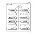
- FIG. 1 is a block diagram showing an example of the configuration of the signal control apparatus 100 of the present embodiment.
- the signal control device 100 includes a CPU 10 that controls the entire device, a traffic volume acquisition unit 11, a communication interface 12, a vehicle number identification unit 13, a vehicle number calculation unit 14, a determination unit 15, a storage unit 16, a current time calculation unit 17, A cycle length calculation unit 18, a green light time correction unit 19, a traffic jam determination unit 20, a selection unit 21, a system section setting unit 22, and the like are provided.
- the signal control device 100 can be incorporated in a traffic signal controller installed near the intersection, or can be configured as a server installed in a traffic control center or the like.
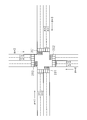
- FIG. 2 is a schematic diagram illustrating an example of an intersection that is signal-controlled by the signal control apparatus 100 according to the present embodiment.
- FIG. 2 is an example in the case of left-hand traffic, and in the case of right-hand traffic, the lane is reversed left and right.
- a vehicle detector (not shown) is installed at the inflow of the intersection.
- the vehicle sensor is an ultrasonic sensor, an image sensor, or the like, and passes through a predetermined position of a predetermined lane (for example, a stop line or a point tens of meters upstream from the intersection) of the inflow path flowing into the intersection.
- Sensing information such as the number of vehicles (traffic volume) and occupation ratio is calculated, and the calculated sensing information is transmitted to the signal control device 100.
- the number of vehicles (traffic volume) can also acquire probe data in real time from the vehicle which passes an intersection. At the same time, using this probe data, the blur rate can be obtained.
- the traffic volume acquisition unit 11 has a function as a number acquisition unit, and acquires the number of vehicles passing through a predetermined position of a predetermined lane of the inflow path flowing into the intersection.
- the predetermined lane may be any one lane, for example, a typical lane, or a dedicated lane such as a right turn lane or a left turn lane.
- the predetermined lane may be an entire lane.
- the predetermined position can be a stop line before the intersection or a point at a required distance (for example, several tens of meters upstream) from the intersection.
- the communication interface 12 receives signal information including a signal control parameter of the traffic signal controller from a server of the traffic control center.
- the communication interface 12 functions as a communication interface with the traffic signal controller installed near the intersection.
- the vehicle number specifying unit 13 has a function as a number specifying unit, and determines the number of vehicles passing through a predetermined position from the first time point to the second time point after the start of the green signal for the inflow path as the second time point. Specify multiple times while updating until the end of the green light.
- the time from the first time point to the second time point is also referred to as unit time p (seconds).
- the unit time p can be, for example, 10 seconds, but is not limited thereto, and can be, for example, about 11 to 30 seconds.
- the vehicle number specifying unit 13 When the update cycle at the second time point is expressed in N (seconds), the vehicle number specifying unit 13 indicates the number of vehicles passing a predetermined position (for example, a stop line) during the past p (seconds) every N (seconds). Identify.
- the update period N can be 1 second, for example, but is not limited to 1 second, and can be any one of 2 to 5 seconds, for example.
- the vehicle number calculation unit 14 has a function as a number calculation unit, and whenever the second time point is updated, the number of vehicles per predetermined time passing through a predetermined position based on the number of vehicles specified by the vehicle number specification unit 13 is calculated. calculate.
- the predetermined time can be 1 second, for example, but may be 1 hour or the like.
- the number of vehicles per predetermined time is also referred to as a profit rate. That is, the vehicle number calculation unit 14 repeatedly calculates the profit rate (units / second) within the unit time p at the update period N.
- the term “gain ratio” is mainly used for the sake of simplicity.
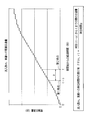
- FIG. 3 is an explanatory diagram showing an example of the accumulated traffic volume after the start of the green light on the inflow path at the intersection.
- the horizontal axis shows the elapsed time (seconds) from the start of the green light, and the vertical axis shows the cumulative traffic volume.
- the current time is defined as the second time point (time t), and the time point from the second time to the past unit time p is defined as the first time point (time (tp)).
- the rate of blurring FR (m, n) ⁇ traffic volume from time (tp) to time t ( The number of vehicles) ⁇ / unit time p can be calculated.
- the vehicle number calculation unit 14 repeatedly calculates the gain rate FR (m, n) within a unit time at an update cycle N (for example, 1 second).
- the average loss rate FR-ave (m) of the inflow channel m can be obtained by averaging FR (m, 1) and FR (m, 2) in the case of two lanes, and in the case of three lanes, It can be determined by the average of FR (m, 1), FR (m, 2) and FR (m, 3).
- the maximum yield rate FR-max (m) of the inflow channel m is the maximum value of FR (m, 1) and FR (m, 2) in the case of two lanes, and FR ( It is the maximum value of m, 1), FR (m, 2) and FR (m, 3).
- the blur rate FR (m) of the inflow channel m may be the average blur rate FR-ave (m) of the inflow channel m or the maximum blur rate FR-max (m) of the inflow channel m.
- the traffic manager can decide which to select.
- the determination unit 15 determines signal control parameters at the intersection based on the yield rate (the number of vehicles per predetermined time) within the unit time calculated by the vehicle number calculation unit 14.
- the traffic processing capacity at the intersection is increasing in the time zone when the profit rate calculated by the vehicle number calculation unit 14 is increased every N update cycles. In the time zone when the profit rate reaches the maximum point (maximum value), the traffic processing capacity is also maximum. However, it is considered that the traffic processing capacity gradually decreases from the maximum state in the time period when the profit rate decreases from the maximum point.
- the deciding unit 15 determines the inflow path at a time point (the time when the maximum point elapses) when the profit rate (the profit rate FR (m) of the inflow path m) within the unit time calculated by the vehicle number calculation unit 14 decreases from the maximum point.
- the signal control parameter so as to be the end point (canceling timing) of the green light time for m, it is possible to improve (optimize) the traffic processing capacity on the inflow path (intersection).
- the first calculation method is a method of directly adopting the profit rate (the profit rate FR (m) of the inflow channel m) within the unit time calculated by the vehicle number calculation unit 14.
- FIG. 4 is an explanatory diagram showing a calculation method at the time when the blurring rate FR (m) of the inflow channel m passes the maximum point by the signal control device 100 of the present embodiment.
- the horizontal axis indicates the elapsed time (seconds) from the start of the green signal
- the vertical axis indicates the rate of gain within the unit time.
- the number-of-vehicles calculation unit 14 has a function as a maximum value specifying unit, and specifies the maximum value of the profit rate FR (m) of the inflow channel m that is repeatedly calculated every update period N. That is, the vehicle number calculation unit 14 specifies the maximum point (maximum value) when the profit rate within the unit time gradually increases after the start of the green light.
- the rate of increase in unit time decreases from the maximum value by a predetermined number of seconds (for example, 5 to 10 seconds) every predetermined update period N (decrease predetermined time point), or a predetermined number of updates.
- the time point that decreases each time is the time point when the maximum point has elapsed.
- the point in time when the maximum point has passed is represented by FR-peak (m).
- the time point FR-peak (m) at which the maximum point has passed may be the last time point t1 of the time when the blur rate is the maximum point. It may be a time point t2 when a predetermined number of seconds (for example, 5 to 10 seconds) have elapsed since the time point t1.
- the determination unit 15 determines the time from the start point of the green signal for the inflow path m to the time point FR-peak (m) when the maximum point has elapsed as the green signal time for the inflow path m.
- the time point at which the rate of increase in unit time decreases after the maximum point is reached is determined to be the timing at which the green signal stops, and the green signal time for the inflow path is determined.
- the second calculation method is a method in which the profit rate within a unit time calculated by the vehicle number calculation unit 14 (the profit rate FR (m) of the inflow channel m) and statistics for a certain period are used together.
- the calculated rate of gain within the unit time (the rate of increase FR of the inflow channel m (m)) is set to a certain time zone (for example, 7 am, 8 am, 6 pm on weekdays)
- a certain days for example, 5 days
- a statistical value for a certain day in a certain time zone at which the time point FR-peak (m) when the maximum point has passed is defined as a statistical time point FR-peak-sta (m).
- the point in time when the maximum point calculated by the first calculation method has elapsed is represented by the actual measurement point FR-peak-real (m).
- FR ⁇ peak (m) ⁇ ⁇ measured time FR ⁇ peak ⁇ real (m) + (1 ⁇ ) ⁇ statistic time FR ⁇ peak ⁇ sta (m).
- the third calculation method is a method that employs only statistical values for a certain period. That is, the third calculation method is a method in which the statistical time point FR-peak-sta (m) calculated by the second calculation method is used as the time point FR-peak (m) when the maximum point has passed. In this case, in order to improve the accuracy, it is possible to collect the statistics for the past several weeks instead of for the past certain days (for example, for five days). Further, when statistical data is accumulated, it is possible to expect improvement in accuracy by dividing and accumulating according to the moon, weather, and the like.
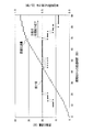
- FIG. 5 is an explanatory diagram showing an example of how traffic processing capacity is optimized by the signal control device 100 of the present embodiment.
- the horizontal axis indicates the elapsed time (seconds) from the start of the green light
- the vertical axis indicates the profit rate (units / second) and the accumulated traffic volume (units) within the unit time.
- the cumulative traffic volume and the profit rate are plotted.
- the cycle length based on the conventional MODERATO control (for example, control based on the present load factor) is 180 seconds
- the split of one inflow path corresponding to the intersection is 50% (green light time: 90 seconds)
- the other The split of the inflow channel is 50% (green signal time: 90 seconds).
- FIG. 5 also shows the profit rate within a unit time (10 seconds) calculated by the signal control apparatus 100 of the present embodiment.
- the blur rate gradually increases after the start of the blue signal, and reaches a maximum point (maximum value) when about 20 seconds elapse from the start of the blue signal. Thereafter, until about 70 seconds elapse from the start of the green light, the blur rate maintains the maximum point. After about 70 seconds from the start of the green light, the blur rate gradually decreases. For this reason, the traffic processing capacity can be maximized (optimized) for the inflow channel by cutting off the green light when about 70 seconds have elapsed from the start of the green light.
- the maximum yield rate time is the FR-peak (m) when the maximum blur rate has passed.
- m the maximum yield rate time
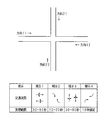
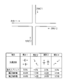
- FIG. 6 is an explanatory diagram showing an example of the inflow path of the single intersection and the present configuration.
- the direction of each inflow channel is defined as direction 11, direction 12, direction 21, and direction 22.
- Current indications for one direction 11 and direction 12 facing each other at the intersection are current indications 1 and 2
- current indications for the other directions 21 and 22 opposite each other at the intersection are current indications 3 and 4. ing.
- Each indication has a realization time in seconds consisting of a minimum guaranteed number of seconds (for example, a safe number of seconds for a pedestrian crossing a pedestrian crossing) and a maximum number of seconds (depending on the location of the intersection).
- a minimum guaranteed number of seconds for example, a safe number of seconds for a pedestrian crossing a pedestrian crossing
- a maximum number of seconds depending on the location of the intersection.
- Each representation can vary within this range.
- the maximum number of seconds is set as an operational limit in consideration of the waiting time of a driver or a pedestrian in signal control.
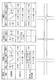
- FIG. 7 is an explanatory diagram showing an example of determining control parameters at a single intersection by the signal control apparatus 100 according to the present embodiment.
- the control parameters shown in FIG. 7 are calculated for the intersection shown in FIG. First, description 1 will be described.
- the maximum yield rate time corresponding to the current indication 1 can be obtained by the maximum value of the maximum yield rate time in the direction 11 and the maximum yield rate time in the direction 12. For example, if the maximum yield rate time in the direction 11 is 60 seconds and the maximum blur rate time in the direction 12 is 53 seconds, the maximum blur rate time corresponding to the current indication 1 is 60 seconds. Here, since 60 seconds is within the realization range, it can be adopted as it is.
- the maximum yield rate time corresponding to the present indication 2 can be obtained by the maximum value of the maximum yield rate time of the right turn lane in the direction 11 and the maximum yield rate time of the right turn lane in the direction 12. For example, if the maximum turn rate time for a right turn in direction 11 is 21 seconds and the maximum turn rate time for a right turn in direction 12 is 23 seconds, the maximum turn rate time corresponding to the present indication 2 is 23 seconds. Here, since 23 seconds is out of the realization range, the maximum number of seconds is shortened to 20 seconds, and the shortened 20 seconds is adopted.
- the determination unit 15 determines the maximum number of seconds as the green signal time when the green signal time exceeds the maximum number of seconds.
- the maximum limit number of seconds is determined by, for example, the location condition of an intersection and is the maximum number of seconds for avoiding useless blue time. Thereby, useless blue time can be avoided.
- the maximum yield rate time corresponding to the present indication 3 can be obtained by the maximum value of the yield rate maximum time in the direction 21 and the maximum yield rate time in the direction 22. For example, if the maximum yield rate time in the direction 21 is 22 seconds and the maximum blur rate time in the direction 22 is 29 seconds, the maximum blur rate time corresponding to the current indication 3 is 29 seconds. Here, since 29 seconds is out of the realization range, it is raised to 30 seconds, which is the minimum guaranteed number of seconds, and the raised 30 seconds is adopted.
- the determining unit 15 determines the minimum guaranteed number of seconds as the green signal time when the green signal time is less than the minimum guaranteed number of seconds.
- the minimum guaranteed number of seconds is, for example, a safe number of seconds for a pedestrian crossing a pedestrian crossing. As a result, a safe number of seconds for a pedestrian crossing the pedestrian crossing can be secured.
- the determination unit 15 determines the longer one as the green signal time when the green signal time for one inflow path facing the intersection and the green signal time for the other inflow path are different. For example, if the green light time for one inflow route is short and the green light time for the other inflow route is long, if the shorter one is determined as the green light time, the green light will be cut off before the traffic processing capacity of the other inflow route reaches its maximum. As a result, it is impossible to improve the traffic processing capability in the present indication. By determining the longer one as the green light time, it is possible to improve the traffic processing capability for the display of the inflow path facing at the intersection.
- the lower display 4 is given as 10 seconds fixed, so 10 seconds is adopted as it is.
- the maximum yield rate time green light time
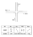
- FIG. 8 is an explanatory diagram showing an example of an inflow path of a single intersection to which a signal control command is given and an example of the present configuration.
- the configuration of the intersection is the same as in the example of FIG.
- command splits of 50%, 10%, 30%, and 10% are given to the current indications 1 to 4, respectively, as signal control commands.
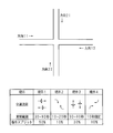
- FIG. 9 is an explanatory diagram showing an example of control parameters determined by the signal control apparatus 100 of the present embodiment.
- the control parameters shown in FIG. 9 are calculated for the intersection shown in FIG.
- the control parameters determined by the signal control device 100 are the same as those in the example of FIG. That is, it is assumed that the maximum yield rate time corresponding to current indication 1, current indication 2, current indication 3 and current indication 4 is 60 seconds, 20 seconds, 30 seconds and 10 seconds, respectively.
- the number of seconds before correction is obtained by recalculating the maximum yield rate time determined (calculated) for each display according to the command split.
- the designated indication is “presentation 1”.
- the designated indication may be, for example, the result of maximum load factor, fixed setting by the traffic manager, setting that changes with time, automatic judgment due to traffic jams, etc., and must comply with the split. It is a display. Since the current indication 1 is the designated current indication, it is necessary to make the maximum yield rate time 60 seconds for the current indication 1 be the command split 50% of the current indication 1. That is, if the cycle length is 120 seconds, the split shown in the present example 1 is 50%. In this case, the number of seconds before correction of the current indication 1 is 60 seconds.
- the command splits of the other indications 2, 3, and 4 are 10%, 30%, and 10% (however, fixed for 10 seconds). 2.
- the number of seconds before correction for current indication 3 and current indication 4 is 12 seconds, 36 seconds, and 10 seconds (fixed).
- the maximum yield rate time should be 12 seconds, but is a fixed 10 seconds, and therefore, a surplus number of seconds (2 seconds) is generated. For this reason, it is necessary to allocate the surplus number of seconds (2 seconds) to any of the indications.
- the number of seconds after correction is the number of seconds after the surplus seconds (2 seconds) are assigned to the display.
- the number of seconds before correction of the display 2 is set to 14 seconds after correction.
- the cycle length is 120 seconds.
- the display time calculation unit 17 determines a split of one predetermined display (designated display) and the one display among a plurality of displays at the intersection. Based on the green light time determined by the unit 15, the green light time of other displays other than the one current display is calculated.
- the presenting of one opposing inflow path at the intersection is represented as presenting 1 (left turn straight forward and right turn), presenting 2 (right turn), and the other facing inflow path is represented as present 3 (left turn straight forward and right turn). ) And present 4 (turn right).
- the current indication 1 is a predetermined indication
- the command split of the indication 1 is 50%.
- the green light times determined by the determination unit 15 for the current indications 1, 2, 3, and 4 are 60 seconds, 12 seconds, 36 seconds, and 10 seconds, respectively.
- the designated indication may be set manually in advance, or may be switched to a direction where there is traffic on the inflow path corresponding to the indication or a indication with a large amount of traffic (automatic selection). In the case of automatic selection, when a plurality of indications satisfy a condition, it is possible to compare cycles corresponding to each indication split and select a cycle that maximizes the intersection processing capability.
- the determination unit 15 adds the green signal times of the current indication 2, the current indication 3 and the current indication 4 once determined to the green light time of the current indication 1 so that the value becomes 120 seconds.
- Each green light time shown in FIG. 4 is determined. For example, when adding the extra number of seconds so that the cycle length is 120 seconds, the green light time can be assigned to the indication that is shortest. Thereby, it is possible to observe a predetermined split (command split).
- the command split may be a value obtained by adding the insufficient seconds to the insufficient display. it can.
- the load factor can be increased.
- FIG. 10 is a schematic diagram showing an example of an intersection of system control. Assume that intersections C1 to C6 exist as shown in FIG. Assume that the intersections C1 to C3 constitute a system section A, and the intersections C4 to C6 constitute a system section B. In this case, the intersections C1 to C3 in the system section A are system controlled with the same cycle length (for example, 150 seconds). Similarly, the intersections C4 to C6 in another system section B are system-controlled with the same cycle length (for example, 120 seconds different from the system section A).
- FIG. 11 is an explanatory diagram showing an example of determining control parameters at the system control intersection by the signal control apparatus 100 according to the present embodiment.
- the intersections in the system section are defined as C1, C2, and C3.
- the calculation examples of the green signal time for the indications 1 to 4 of the intersection C1 by the conventional method are 80 seconds, 20 seconds, 40 seconds, and 10 seconds, respectively.
- the calculation examples of the green signal time for the present indications 1 and 2 of the intersection C2 by the conventional method are 110 seconds and 40 seconds, respectively.
- the calculation examples of the green signal time for the indications 1 to 4 of the intersection C3 by the conventional method are 80 seconds, 20 seconds, 40 seconds, and 10 seconds, respectively.
- the cycle lengths of the intersections C1 to C3 are the same in 150 seconds.
- the “number of seconds determined by the profit rate” by the signal control device 100 for the indications 1 to 4 of the intersection C1 are 60 seconds, 20 seconds, 30 seconds, and 10 seconds, respectively.
- the “determined number of seconds based on the gain rate” by the signal control device 100 for the indications 1 to 4 of the intersection C3 is 86 seconds, 20 seconds, 44 seconds, and 10 seconds, respectively.
- the intersection C2 is assumed to be an intersection with a small amount of traffic on the secondary road, and the calculation process of the maximum yield rate by the signal control device 100 is omitted.
- the determination unit 15 determines a green signal time for the inflow path of each intersection of the system section configured by a plurality of intersections and controlled with the same cycle length.
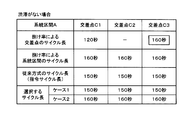
- FIG. 12 is an explanatory diagram showing a calculation example of control parameters when there is no traffic jam by the signal control apparatus 100 according to the present embodiment.
- the cycle length calculation unit 18 calculates the cycle length of each intersection based on the green signal time for the inflow path of each intersection determined by the determination unit 15.
- the cycle length may be calculated by adding up the green light times for each display.
- the cycle length of the intersection according to the blur rate is calculated as 120 seconds at the intersection C1 and 160 seconds at the intersection C3.
- the determining unit 15 determines the maximum cycle length among the cycle lengths calculated by the cycle length calculating unit 18 as the cycle length of the system section. In the example of FIG. 12, 160 seconds, which is the maximum cycle length among the cycle lengths calculated by the cycle length calculation unit 18, is determined as the cycle length of the system section based on the profit rate.
- the intersections of the system sections are C1, C2, and C3, and the cycle lengths calculated by the cycle length calculation unit 18 for the intersections C1, C2, and C3 are 120 seconds and 140 seconds, respectively. 160 seconds.
- the determination unit 15 determines the cycle length of each intersection in the system section as the maximum value of 160 seconds.
- the cycle length calculation unit 18 uses the common cycle using the green signal time in which the traffic processing capacity is optimized based on the profit rate. You can ask for the length.
- the communication interface 12 has a function as a cycle length acquisition unit, and acquires predetermined cycle lengths predetermined for a plurality of intersections.
- the designated cycle length is calculated by a traffic control center or the like and can be a cycle length calculated by MODERATO control.
- 150 seconds is given to the intersections C1 to C3 as the cycle length of the conventional method.
- the traffic jam judgment unit 20 judges whether or not there is a traffic jam on any of the inflow paths of the plurality of intersections. In the example of FIG. 12, it is assumed that there is no traffic jam. Further, the traffic jam determination unit 20 not only determines the presence / absence of traffic jams, but also determines the presence / absence of a saturated state (for example, traffic demand is a traffic processing amount state, not traffic jams) instead of traffic jams. it can. In the following description, the occurrence of traffic congestion includes the case where the vehicle is saturated.
- the selection unit 21 selects either the acquired designated cycle length or the cycle length determined by the determination unit 16.
- case 1 and case 2 are listed as the cycle lengths to be selected.
- Case 1 shows the case of selecting the cycle length of the conventional method
- Case 2 shows the case of selecting the cycle length of the system section according to the profit rate.
- the longer cycle length can be adopted.
- the cycle length fluctuation range minimum to maximum
- the cycle length is within the registered fluctuation range. Can be corrected.
- FIG. 13 is an explanatory diagram showing an example of split correction by the signal control apparatus 100 according to the present embodiment.
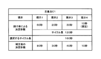
- the green signal time correction unit 19 calculates the green signal time for the inflow path of another intersection according to the difference between the cycle length of the other intersection other than the intersection for which the maximum cycle length is calculated and the maximum cycle length among the plurality of intersections. to correct. As shown in FIG. 12, the intersection where the maximum cycle length is calculated is C3, and the other intersection is C1.
- the cycle length of the intersection C1 is changed from 120 seconds, which is the cycle length based on the determined number of seconds based on the profit rate (the cycle length of the intersection based on the profit ratio), to the cycle length of the system section (the cycle length to be selected). ) which is 160 seconds.
- the difference between the cycle length of the intersection C1 (120 seconds) and the maximum cycle length (160 seconds) is 40 seconds.
- the green light time correction unit 19 corrects the green light time by redistributing the difference according to the ratio of the green light time before correction.
- the difference of 40 seconds is changed to the current indications 1 to 3 in accordance with the ratio of the green light time 60 seconds, 20 seconds, and 30 seconds of the current indications 1 to 3.
- the determined number of seconds after correction of current display 1 can be obtained by the ratio of the number of seconds (60 seconds) of current display 1 before correction + difference (40 seconds) ⁇ the ratio of current display 1 [60 / (60 + 20 + 30)]. it can.
- the first digit of the number of seconds can be rounded to 0, 5, or 10 as appropriate.
- the green signal times of the present indications 1 to 4 after correction are, for example, 80 seconds, 30 seconds, 40 seconds, and 10 seconds (fixed seconds).
- the corrected green light time is outside the upper and lower limit seconds, it can be further corrected so as to be within the upper and lower limits. As a result, if there is a surplus, it may be redistributed according to the ratio of the displayed green light time that can be added. Further, if there is a shortage, it may be redistributed according to the ratio of the displayed green light time that can be subtracted.
- the green light time can be given only to the inflow road on the main road side without giving the green light time to the inflow road on the secondary road side.
- FIG. 14 is a schematic diagram illustrating an example of reconstruction of a system section when there is traffic congestion in the system section.
- the cycle lengths of the intersections according to the yield rates of the intersections C11 to C16 are 120 seconds, 130 seconds, 140 seconds, 110 seconds, and 100, respectively. Second and 90 seconds.
- the cycle length of the system section D can be either the command cycle length of 100 seconds or the maximum cycle length of 140.
- the traffic processing capacity is required to be maximized at the traffic congestion intersection, and at the same time smooth traffic is required at the location or section where there is no traffic congestion.
- traffic congestion congestion intersection or traffic congestion point
- the traffic processing capacity is required to be maximized at the traffic congestion intersection, and at the same time smooth traffic is required at the location or section where there is no traffic congestion.
- unnecessary waiting time other than the traffic jam intersection may occur, so it is necessary to review the system section.
- the system segment setting unit 22 has a plurality of intersections in which the cycle length of each intersection calculated by the cycle length calculation unit 18 satisfies a predetermined condition. In some cases, a plurality of intersections are set as new system sections.
- the predetermined condition is that a difference in cycle length can be set to a predetermined threshold value or less.
- intersections C1 and C2 are set as the same system section.
- the selection unit 21 selects the cycle length determined by the determination unit 15 when the traffic determination unit 20 determines that a traffic jam has occurred.
- the cycle length of the intersection based on the profit rate is not the cycle length of the system section D1, but the designated cycle length of 100 seconds.
- the maximum cycle length of 140 seconds is adopted.
- the cycle length of the system section D2 is the maximum of the designated cycle length of 100 seconds or the cycle length of the intersection according to the profit rate. Any of the cycle lengths of 110 seconds may be adopted. In the example of FIG. 14, a command cycle length of 100 seconds is employed.
- the longer cycle length can be adopted by comparing the designated cycle length with the maximum cycle length of the intersection cycle length according to the profit rate. Regardless of which cycle length is used, the cycle length fluctuation range (minimum to maximum) should be registered in advance in the traffic control system, etc., and the cycle length should be corrected to be within the registered fluctuation range. Can do.
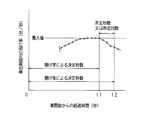
- FIG. 15 is an explanatory diagram illustrating an example of calculating the blur rate within different unit times by the signal control apparatus 100 according to the present embodiment.
- the horizontal axis indicates the elapsed time (seconds) from the start of the green light
- the vertical axis indicates the profit rate (units / second) and the accumulated traffic volume (units) within the unit time.
- the cumulative traffic volume and the profit rate in units of 10 seconds and 11 seconds are plotted.
- the example of FIG. 15 is an example in which the profit rate when the unit time p is 10 seconds (in units of 10 seconds) and the profit rate when the unit time p is 11 seconds (in units of 11 seconds) are calculated simultaneously.
- the vehicle number specifying unit 13 specifies the number of vehicles for each of a plurality of time differences having different time differences from the first time point to the second time point.
- the vehicle number calculation unit 14 calculates the number of vehicles per predetermined time for each of a plurality of time differences. Assuming that the unit time p (seconds) from the first time point to the second time point is used, the unit time p1 (for example, 10 seconds) and the unit time p2 (for example, 11 seconds) can be obtained. That is, the vehicle number calculation unit 14 calculates the profit rate within the unit time p1 and the profit rate within the unit time p2.
- the determining unit 15 determines signal control parameters at the intersection based on the profit rate (the number of vehicles per predetermined time) within a unit time calculated by the vehicle number calculating unit 14 for each of a plurality of time differences. For example, the determination unit 15 generates a green signal for the inflow path when the blur rate in the unit time p1 calculated by the vehicle number calculation unit 14 decreases from the maximum point and the blur rate in the unit time p2 decreases from the maximum point.
- the signal control parameter is determined to be the end point of time (censoring timing). In the example of FIG. 15, the time at which it is considered that both the 10-second unit blur rate and the 11-second unit blur rate have decreased from the maximum point is the maximum blur rate time (in the example of FIG. 15, the elapsed time from the start of the green signal). , Approximately 45 seconds).
- maximum yield rate By performing a moving average process on the maximum point of the yield rate (maximum yield rate), if the number of times (seconds) that falls below a certain set value from the maximum yield rate is exceeded, it may be determined that the yield rate has decreased. it can.
- FIG. 16 is an explanatory diagram showing an example of the restoration of profit rate calculation.
- the horizontal axis indicates the elapsed time (seconds) from the start of the green light
- the vertical axis indicates the profit rate (units / second) and the accumulated traffic volume (units) within the unit time.
- the cumulative traffic volume in direction 11 and the cumulative traffic volume in direction 12, the yield rate in direction 11, and the yield rate in direction 12 are plotted.
- the larger value of the maximum rate of blurring rate in a plurality of directions Will be adopted.
- the maximum blur rate time in only the direction 12 is determined. Even at this time, if recovery due to a re-increase in the rate of blurring in direction 11 is observed before it is determined that the maximum rate of blurring rate in direction 12 has elapsed, the rate of gain in the multiple directions of direction 11 and direction 12 is again maximized. A method of judging time is also conceivable.
- the determination unit 15 determines the green signal time for the other inflow path before determining the green signal time for the other inflow path.
- the green light time is determined based on the time until the predetermined time when the number of vehicles per predetermined time decreases from the maximum value specified by the vehicle number calculation unit 14 in both inflow paths. To do.
- the case where the number of vehicles per predetermined time on one inflow path decreases after a predetermined time is, for example, a case where the decrease continues after a predetermined time when the rate of increase in unit time decreases after passing the maximum point.
- the time before determining the green light time for the other inflow path is, for example, before the predetermined time point when the blur rate within the unit time decreases after passing the maximum point, that is, before the green light time is determined.
- the rate of gain in direction 12 is the maximum when about 12 seconds have elapsed from the start of the green light, and has decreased after about 16 seconds.
- the blurring rate in direction 11 becomes maximum when about 35 seconds have elapsed from the start of the green light. From about 35 seconds after the start of the green light, the blur rate in direction 11 increases almost consistently.
- the profitability in direction 12 has been revived to increase. Therefore, in the case of determining the maximum yield rate in a plurality of directions and before it is determined that the direction 11 has passed the maximum rate of increase, the direction 12 is determined again, and the respective rates of increase are determined. It is desirable to cut off the green light when it falls from the maximum point. In other words, even in a traffic situation where the yield rate once decreases from the maximum value on one inflow channel and then increases again, it is possible to determine a decrease from the maximum value of both yield rates. Can be discontinued.
- the maximum yield rate can be determined again in all registered directions.
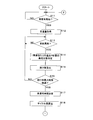
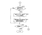
- 17 and 18 are flowcharts showing a first example of the processing procedure of the signal control apparatus 100 according to the present embodiment.
- the processing subject will be described as the CPU 10.
- the CPU 10 determines whether or not the green signal is started (S11). If the green signal is not started (NO in S11), the process of step S11 is continued. When it is a green signal start (it is YES at S11), CPU10 acquires traffic volume (S12).
- the CPU 10 determines whether or not it is the update cycle N (for example, 1 second) (S13), and if it is not the update cycle N (NO in S13), the process of step S13 is continued.
- the update cycle N YES in S13
- the CPU 10 specifies the number of vehicles per lane in the past p seconds (S14), and calculates the profit rate within the unit time p (S15).
- the CPU 10 determines whether or not the maximum yield rate time has elapsed by comparing the calculated yield rate within the unit time and the maximum rate of the yield rate (S16). In addition, the process of step S14, S15 is performed about each inflow path of an intersection.
- the CPU 10 determines the green signal time for each display (S17) and calculates the cycle length of the intersection (S18).
- the CPU 10 determines whether there is a designated split command split (S19). If there is a designated split command split (YES in S19), the CPU 10 calculates the cycle length based on the command split (S20) and designates the designated split. A green signal time for a display other than the display is calculated (S21).
- the CPU 10 When there is no designated display command split (NO in S19), the CPU 10 performs the process of step S22 described later without performing the processes of steps S20 and S21. The CPU 10 determines whether or not to end the process (S22). If the process is not ended (NO in S22), the process after step S11 is repeated, and if the process is ended (YES in S22), the process ends. To do.
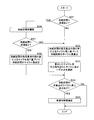
- FIG. 19 is a flowchart showing a second example of the processing procedure of the signal control apparatus 100 of the present embodiment.
- the CPU 10 determines whether or not there is a traffic jam in the system section (S31). If there is no traffic jam (NO in S31), the CPU 10 calculates the cycle length of the system section based on the cycle length based on the yield rate of each intersection of the system section. Then, either the calculated cycle length or the commanded cycle length is selected (S33).
- the CPU 10 determines whether or not there is a difference in the cycle lengths of the intersections in the system section (S34). If there is a difference (YES in S34), the green light time is corrected (S35), and the process ends. If there is no difference (NO in S34), the CPU 10 ends the process without performing the process of step S35.
- the CPU 10 reconstructs the system section (S36) and determines whether there is a traffic jam in the reconstructed system section (S37). When there is no traffic jam in the system section (NO in S37), that is, for the system section where there is no traffic jam, the CPU 10 performs the process of step S32.
- the CPU 10 determines the cycle length of the system section based on the cycle length according to the yield rate of each intersection of the system section. (S38), the process of step S34 is performed.
- the signal control apparatus can be realized using a general-purpose computer including a CPU (processor), a RAM, and the like. That is, as shown in FIGS. 17, 18, and 19, a computer program that defines the procedure of each process (step of a method executed by the CPU) is loaded into a RAM provided in the computer, and the computer program is loaded into the CPU (processor).
- the signal control device can be realized on the computer.
- the computer program that defines the steps of the method executed by the CPU as shown in FIGS. 17, 18 and 19 can be recorded on a non-transitory recording medium that can be read by the computer.
- the traffic processing capacity at the intersection can be maximized (optimized) by determining the maximum yield rate time and performing traffic signal control using the determined signal control parameters. .
- the green signal time has been described for the sake of simplicity. However, in actual operation, a yellow signal or a red signal that is a clearance time (loss time) can be considered.
- the determination unit determines the green signal time for the inflow path
- the minimum guaranteed second is set as the green signal time. I am going to decide.
- the determining unit determines the minimum guaranteed seconds as the green signal time if the green signal time is less than the minimum guaranteed seconds.
- the minimum guaranteed number of seconds is, for example, a safe number of seconds for a pedestrian crossing a pedestrian crossing. As a result, a safe number of seconds for a pedestrian crossing the pedestrian crossing can be secured.
- the determining unit determines the green signal time for the inflow path, when the green signal time exceeds the maximum number of seconds, the maximum number of seconds is determined as the green signal time. I have to do it.
- the determining unit determines the maximum number of seconds as the green signal time when the green signal time exceeds the maximum number of seconds.
- the maximum number of seconds is determined by, for example, the location conditions of an intersection, and is often set as an operational maximum number of seconds in consideration of the waiting time of a driver or a pedestrian in signal control.
- the determining unit determines the longer one as the green signal time when the green signal time for one inflow path facing the intersection and the green signal time for the other inflow path are different. It is.
- the determining unit determines the longer one as the green signal time when the green signal time for one inflow path facing the intersection and the green signal time for the other inflow path are different. For example, if the green light time for one inflow route is short and the green light time for the other inflow route is long, if the shorter one is determined as the green light time, the green light will be cut off before the traffic processing capacity of the other inflow route reaches its maximum. As a result, it is impossible to improve the traffic processing capability in the present indication. By determining the longer one as the green light time, it is possible to improve the traffic processing capability for the display of the inflow path facing at the intersection.
Landscapes
- Physics & Mathematics (AREA)
- General Physics & Mathematics (AREA)
- Traffic Control Systems (AREA)
Abstract
交差点での交通処理能力を向上させることができる信号制御装置、コンピュータプログラム、記録媒体及び信号制御方法を提供する。 信号制御装置は、交差点に流入する流入路の所定車線の所定位置を通過する車両台数を取得する台数取得部と、流入路に対する青信号の開始以降の第1時点から第2時点までの間に所定位置を通過する車両台数を、第2時点を更新しつつ複数回特定する台数特定部と、第2時点を更新する都度、特定した車両台数に基づいて所定位置を通過する所定時間当たりの車両台数を算出する台数算出部と、算出した所定時間当たりの車両台数に基づいて交差点での信号制御パラメータを決定する決定部とを備える。
Description
本発明は、信号制御装置、該信号制御装置を実現するためのコンピュータプログラム、該コンピュータプログラムを記録した記録媒体及び信号制御方法に関する。
従来の交通信号制御では、サイクル長、スプリット、オフセット等の信号制御パラメータを交通状況に応じて更新するMODERATO(Management by Origin-Destination Related Adaptation for Traffic Optimization)制御が広く運用されている。サイクル長は、信号表示が一巡する時間であり、スプリットは、サイクル長に対する各現示に割り当てられる時間の長さの割合である。現示とは、1つの交差点において一組の交通流に対して同時に付与される通行権又は通行権が割り当てられている時間帯である。
交差点でのスプリットは、交通処理能力に寄与する重要な信号制御パラメータであり、MODERATO制御では、現示ごとに各流入路の負荷率の最大値である現示負荷率を求め、現示負荷率の比で正規化されたスプリットを配分する方式を用いている(非特許文献1参照)。
社団法人交通工学研究所 「改訂交通信号の手引き」丸善、p85、2009年
負荷率は、飽和交通流率に対する単位時間当たりの負荷交通量の割合であり、負荷交通量は、処理交通量(流入台数)と渋滞部に存在する車両台数(捌け残り台数)との合計である。しかし、MODERATO制御では、負荷率などの変量は、比較的長い時間の間の平均的な値を採用しているため、交通量が比較的短い時間の間に変動する場合には、交通処理能力が低下する場合が生じる。
本発明は、斯かる事情に鑑みてなされたものであり、交差点での交通処理能力を向上させることができる信号制御装置、該信号制御装置を実現するためのコンピュータプログラム、該コンピュータプログラムを記録した記録媒体及び信号制御方法を提供することを目的とする。
(1)本発明の実施の形態に係る信号制御装置は、交差点に流入する流入路の所定車線の所定位置を通過する車両台数を取得する台数取得部と、前記流入路に対する青信号の開始以降の第1時点から第2時点までの間に前記所定位置を通過する車両台数を、前記第2時点を該青信号の終了まで更新しつつ複数回特定する台数特定部と、前記第2時点を更新する都度、前記台数特定部で特定した車両台数に基づいて前記所定位置を通過する所定時間当たりの車両台数を算出する台数算出部と、該台数算出部で算出した前記所定時間当たりの車両台数に基づいて前記交差点での信号制御パラメータを決定する決定部とを備える。
(11)本発明の実施の形態に係るコンピュータプログラムは、コンピュータに信号制御させるためのコンピュータプログラムであって、コンピュータを、交差点に流入する流入路の所定車線の所定位置を通過する車両台数を取得する台数取得部と、前記流入路に対する青信号の開始以降の第1時点から第2時点までの間に前記所定位置を通過する車両台数を、前記第2時点を該青信号の終了まで更新しつつ複数回特定する台数特定部と、前記第2時点を更新する都度、特定した車両台数に基づいて前記所定位置を通過する所定時間当たりの車両台数を算出する台数算出部と、算出した前記所定時間当たりの車両台数に基づいて前記交差点での信号制御パラメータを決定する決定部として機能させる。
(12)本発明の実施の形態に係る記録媒体は、コンピュータに信号制御させるためのコンピュータプログラムを記録したコンピュータでの読み取りが可能な非一時的な記録媒体であって、前記コンピュータプログラムは、コンピュータを、交差点に流入する流入路の所定車線の所定位置を通過する車両台数を取得する台数取得部と、前記流入路に対する青信号の開始以降の第1時点から第2時点までの間に前記所定位置を通過する車両台数を、前記第2時点を該青信号の終了まで更新しつつ複数回特定する台数特定部と、前記第2時点を更新する都度、特定した車両台数に基づいて前記所定位置を通過する所定時間当たりの車両台数を算出する台数算出部と、算出した前記所定時間当たりの車両台数に基づいて前記交差点での信号制御パラメータを決定する決定部として機能させる。
(13)本発明の実施の形態に係る信号制御方法は、交差点に流入する流入路の所定車線の所定位置を通過する車両台数を台数取得部が取得するステップと、前記流入路に対する青信号の開始以降の第1時点から第2時点までの間に前記所定位置を通過する車両台数を、前記第2時点を該青信号の終了まで更新しつつ複数回台数特定部が特定するステップと、前記第2時点を更新する都度、特定された車両台数に基づいて前記所定位置を通過する所定時間当たりの車両台数を台数算出部が算出するステップと、算出された前記所定時間当たりの車両台数に基づいて前記交差点での信号制御パラメータを決定部が決定するステップとを含む。
本発明によれば、交差点での交通処理能力を向上させることができる。
[本願発明の実施形態の説明]
(1)本発明の実施の形態に係る信号制御装置は、交差点に流入する流入路の所定車線の所定位置を通過する車両台数を取得する台数取得部と、前記流入路に対する青信号の開始以降の第1時点から第2時点までの間に前記所定位置を通過する車両台数を、前記第2時点を該青信号の終了まで更新しつつ複数回特定する台数特定部と、前記第2時点を更新する都度、前記台数特定部で特定した車両台数に基づいて前記所定位置を通過する所定時間当たりの車両台数を算出する台数算出部と、該台数算出部で算出した前記所定時間当たりの車両台数に基づいて前記交差点での信号制御パラメータを決定する決定部とを備える。
(1)本発明の実施の形態に係る信号制御装置は、交差点に流入する流入路の所定車線の所定位置を通過する車両台数を取得する台数取得部と、前記流入路に対する青信号の開始以降の第1時点から第2時点までの間に前記所定位置を通過する車両台数を、前記第2時点を該青信号の終了まで更新しつつ複数回特定する台数特定部と、前記第2時点を更新する都度、前記台数特定部で特定した車両台数に基づいて前記所定位置を通過する所定時間当たりの車両台数を算出する台数算出部と、該台数算出部で算出した前記所定時間当たりの車両台数に基づいて前記交差点での信号制御パラメータを決定する決定部とを備える。
(11)本発明の実施の形態に係るコンピュータプログラムは、コンピュータに信号制御させるためのコンピュータプログラムであって、コンピュータを、交差点に流入する流入路の所定車線の所定位置を通過する車両台数を取得する台数取得部と、前記流入路に対する青信号の開始以降の第1時点から第2時点までの間に前記所定位置を通過する車両台数を、前記第2時点を該青信号の終了まで更新しつつ複数回特定する台数特定部と、前記第2時点を更新する都度、特定した車両台数に基づいて前記所定位置を通過する所定時間当たりの車両台数を算出する台数算出部と、算出した前記所定時間当たりの車両台数に基づいて前記交差点での信号制御パラメータを決定する決定部として機能させる。
(12)本発明の実施の形態に係る記録媒体は、コンピュータに信号制御させるためのコンピュータプログラムを記録したコンピュータでの読み取りが可能な非一時的な記録媒体であって、前記コンピュータプログラムは、コンピュータを、交差点に流入する流入路の所定車線の所定位置を通過する車両台数を取得する台数取得部と、前記流入路に対する青信号の開始以降の第1時点から第2時点までの間に前記所定位置を通過する車両台数を、前記第2時点を該青信号の終了まで更新しつつ複数回特定する台数特定部と、前記第2時点を更新する都度、特定した車両台数に基づいて前記所定位置を通過する所定時間当たりの車両台数を算出する台数算出部と、算出した前記所定時間当たりの車両台数に基づいて前記交差点での信号制御パラメータを決定する決定部として機能させる。
(13)本発明の実施の形態に係る信号制御方法は、交差点に流入する流入路の所定車線の所定位置を通過する車両台数を台数取得部が取得するステップと、前記流入路に対する青信号の開始以降の第1時点から第2時点までの間に前記所定位置を通過する車両台数を、前記第2時点を該青信号の終了まで更新しつつ複数回台数特定部が特定するステップと、前記第2時点を更新する都度、特定された車両台数に基づいて前記所定位置を通過する所定時間当たりの車両台数を台数算出部が算出するステップと、算出された前記所定時間当たりの車両台数に基づいて前記交差点での信号制御パラメータを決定部が決定するステップとを含む。
台数取得部は、交差点に流入する流入路の所定車線の所定位置を通過する車両台数を取得する。所定車線は、流入路に車線が複数ある場合、任意の1車線でよく、例えば、代表的な車線でもよく、右折専用車線又は左折専用車線などの専用車線でもよい。また、所定車線は、全車線でもよい。所定位置は、交差点手前の停止線又は交差点から所要距離の地点とすることができる。台数取得部は、例えば、交差点の停止線付近に設置された車両感知器から車両台数を取得することができる。
台数特定部は、流入路に対する青信号の開始以降の第1時点から第2時点までの間に所定位置を通過する車両台数を、第2時点を当該青信号の終了まで更新しつつ複数回特定する。第1時点から第2時点までの時間を、単位時間p(秒)とも称する。単位時間pは、例えば、10秒とすることができるが、これに限定されない。第2時点の更新周期をN(秒)で表すと、台数特定部は、N(秒)の都度、過去p(秒)間に所定位置(例えば、停止線)を通過する車両台数を特定する。更新周期Nは、例えば、1秒とすることができる。
台数算出部は、第2時点を更新する都度、台数特定部で特定した車両台数に基づいて所定位置を通過する所定時間当たりの車両台数を算出する。所定時間は、例えば、1秒とすることができるが、1時間等でもよい。所定時間当たりの車両台数は、捌け率とも称する。すなわち、台数算出部は、単位時間p内の捌け率(台/秒)を更新周期Nで繰り返し算出する。
決定部は、台数算出部で算出した所定時間当たりの車両台数に基づいて交差点での信号制御パラメータを決定する。台数算出部は、青信号の開始以降、更新周期Nで単位時間p内の捌け率を繰返し算出する。捌け率が増加している時間帯では、交差点での交通処理能力が増加している。捌け率が最大点(最大値)に到達した時間帯では、交通処理能力も最大となっている。しかし、捌け率が最大点から減少する時間帯では、交通処理能力も最大の状態から徐々に低下していると考えられる。決定部は、台数算出部で算出した単位時間内の捌け率が最大点から低下する時点(最大点を経過する時点)で当該流入路に対する青信号時間の終了時点(打ち切りタイミング)とするように信号制御パラメータを決定することにより、当該流入路(交差点)での交通処理能力を向上(最適化)することができる。
(2)本発明の実施の形態に係る信号制御装置は、前記台数算出部で算出する前記所定時間当たりの車両台数の最大値を特定する最大値特定部を備え、前記決定部は、前記青信号の開始時点から、前記台数算出部で算出する前記所定時間当たりの車両台数が前記最大値特定部で特定した最大値より減少する所定時点までの時間を前記流入路に対する青信号時間として決定するようにしてある。
最大値特定部は、台数算出部で算出する所定時間当たりの車両台数の最大値を特定する。すなわち、最大値特定部は、青信号の開始以降、単位時間内の捌け率が徐々に増加する場合の最大点(最大値)を特定する。決定部は、当該流入路に対する青信号の開始時点から、台数算出部で算出する車両台数が最大値特定部で特定した最大値より減少する所定時点までの時間を当該流入路に対する青信号時間として決定する。
すなわち、当該流入路に対する青信号の開始以降、単位時間内の捌け率が最大点を経過して減少する所定時点を青信号の打ち切りタイミングであると判定して当該流入路に対する青信号時間を決定する。これにより、当該流入路に対する青信号を、交通処理能力が低下する前に終了させることができるので交通処理能力を最適化することができる。
(3)本発明の実施の形態に係る信号制御装置は、前記決定部は、前記交差点で対向する一方の流入路で前記所定時間当たりの車両台数が前記所定時点以降で減少する場合に、他方の流入路に対する青信号時間を決定する前に、前記一方の流入路で前記所定時間当たりの車両台数が再度増加するときは、双方の流入路で前記所定時間当たりの車両台数が前記最大値特定部で特定した最大値より減少する所定時点までの時間に基づいて青信号時間を決定するようにしてある。
決定部は、交差点で対向する一方の流入路で所定時間当たりの車両台数が所定時点以降で減少する場合に、他方の流入路に対する青信号時間を決定する前に、一方の流入路で所定時間当たりの車両台数が再度増加するときは、双方の流入路で所定時間当たりの車両台数が最大値特定部で特定した最大値より減少する所定時点までの時間に基づいて青信号時間を決定する。
一方の流入路で所定時間当たりの車両台数が所定時点以降で減少する場合とは、例えば、単位時間内の捌け率が最大点を経過して減少する所定時点以降、さらに減少を続ける場合である。他方の流入路に対する青信号時間を決定する前とは、例えば、単位時間内の捌け率が最大点を経過して減少する所定時点を経過する前、すなわち未だ青信号時間を決定する前である。すなわち、交差点で対向する一方の流入路の捌け率が最大点から低下し、捌け率最大時間を経過したと判断された場合に、他方の流入路において捌け率最大時間を経過したと判断される前に、一方の流入路の捌け率の再上昇による回復が見られるときは、再度双方の流入路における捌け率最大時間に基づいて、青信号時間を決定する。これにより、一方の流入路において一旦捌け率が最大値から減少した後に再度増加するような交通状況であっても、双方の捌け率の最大値からの減少を判定することができるので、青信号を適切に打ち切ることができる。
(4)本発明の実施の形態に係る信号制御装置は、前記交差点の複数の現示のうち、予め定められている一の現示のスプリット及び該一の現示に対して前記決定部で決定した青信号時間に基づいて、前記一の現示を除く他の現示の青信号時間を算出する現示時間算出部を備える。
現示時間算出部は、交差点の複数の現示のうち、予め定められている一の現示(指定現示)のスプリット及び当該一の現示に対して決定部で決定した青信号時間に基づいて、当該一の現示を除く他の現示の青信号時間を算出する。例えば、交差点の一方の対向する流入路の現示を、現示1(左折直進右折)、現示2(右折)とし、他方の対向する流入路の現示を、現示3(左折直進右折)、現示4(右折)とする。現示1が予め定められている指定現示であるとし、指定現示の指令スプリットを50%とする。また、現示1、2、3、4に対して決定部で決定した青信号時間をそれぞれ60秒、12秒、36秒、10秒とする。また、指定現示は、予め人的に設定するものでもよく、現示に対応する流入路の渋滞がある方向や交通量の多い現示に切り替える(自動選択)でもよい。自動選択の場合で、複数現示が条件を満たした場合、それぞれの現示スプリットに対応するサイクルを比較し、交差点処理能力が最大となるサイクルを選択することも考えられる。
現示1の指定スプリットが50%であるので、サイクル長は、120秒となる(サイクル長に対する現示1の青信号時間60秒の割合を50%としなればならないので、サイクル長は120秒としなければならない)。決定部は、現示1の青信号時間に一旦決定した現示2、現示3及び現示4の青信号時間を加えた値が120秒になるように、現示2、現示3及び現示4それぞれの青信号時間を決定する。例えば、サイクル長を120秒とすべく余剰秒数を加える場合には、青信号時間が最も不足している現示に割り当てることができる。これにより、予め定められた現示のスプリット(指令スプリット)を遵守することができる。上記のような予め与えられたスプリットに基づくことなく、指定された現示の最大捌け率で青時間を決定し、その結果サイクルを求める(サイクルは現示青時間の副産物)方法も考えられる。
(5)本発明の実施の形態に係る信号制御装置は、前記決定部は、複数の交差点で構成され、同一サイクル長で制御される系統区間の各交差点の流入路に対する青信号時間を決定するようにしてあり、前記決定部で決定した各交差点の流入路に対する青信号時間に基づいて各交差点のサイクル長を算出するサイクル長算出部を備え、前記決定部は、前記サイクル長算出部で算出したサイクル長のうち最大のサイクル長を前記系統区間のサイクル長として決定するようにしてある。
決定部は、複数の交差点で構成され、同一サイクル長で制御される系統区間の各交差点の流入路に対する青信号時間を決定する。サイクル長算出部は、決定部で決定した各交差点の流入路に対する青信号時間に基づいて各交差点のサイクル長を算出する。サイクル長の算出は、各現示の青信号時間を合計すればよい。決定部は、サイクル長算出部で算出したサイクル長のうち最大のサイクル長を系統区間のサイクル長として決定する。
例えば、系統区間の交差点をC1、C2、C3とし、交差点C1、C2、C3について、サイクル長算出部が算出したサイクル長がそれぞれ120秒、140秒、160秒とする。決定部は、系統区間の各交差点のサイクル長を最大値である160秒に決定する。1つの系統制御系を構成する信号機群には共通のサイクル長を与える必要があり、捌け率に基づいて交通処理能力が最適化された青信号時間を用いた共通のサイクル長を求めることができる。
(6)本発明の実施の形態に係る信号制御装置は、前記複数の交差点のうち前記最大のサイクル長が算出された交差点以外の他の交差点のサイクル長と前記最大のサイクル長との差分に応じて前記他の交差点の流入路に対する青信号時間を補正する青信号時間補正部を備える。
青信号時間補正部は、複数の交差点のうち最大のサイクル長が算出された交差点以外の他の交差点のサイクル長と最大のサイクル長との差分に応じて他の交差点の流入路に対する青信号時間を補正する。
例えば、交差点C1のサイクル長を120秒から最大のサイクル長である160秒に変更するとする。差分は40秒となる。交差点C1の現示を、現示1、現示2、現示3、現示4とし、現示1~4の青信号時間(補正前の青信号時間)をそれぞれ、60秒、20秒、30秒、10秒(固定秒数)とする。青信号時間補正部は、差分を補正前の青信号時間の比率に応じて再配分することにより、青信号時間を補正する。補正後の現示1~4の青信号時間は、例えば、80秒、30秒、40秒、10秒(固定秒数)となる。これにより、共通のサイクル長を用いる系統制御を行う場合に、捌け率に基づいて交通処理能力が最適化された青信号時間を提供することができる。
(7)本発明の実施の形態に係る信号制御装置は、前記複数の交差点に対して予め定められた指定サイクル長を取得するサイクル長取得部と、前記複数の交差点の流入路のいずれかで渋滞又は飽和状態の少なくとも一方が発生しているか否かを判定する渋滞判定部と、該渋滞判定部で渋滞及び飽和状態が発生していないと判定した場合、前記取得部で取得した指定サイクル長又は前記決定部で決定したサイクル長のいずれか一方を選択する選択部とを備える。
サイクル長取得部は、複数の交差点に対して予め定められた指定サイクル長を取得する。指定サイクル長は、例えば、交通管制センタ等で算出され、MODERATO制御により算出されたサイクル長とすることができる。渋滞判定部は、複数の交差点の流入路のいずれかで渋滞又は飽和状態(例えば、渋滞ではないが交通需要が交通処理量の状態)の少なくとも一方が発生しているか否かを判定する。選択部は、渋滞判定部で渋滞及び飽和状態が発生していないと判定した場合、取得した指定サイクル長又は決定部で決定したサイクル長のいずれか一方を選択する。
系統区間に渋滞及び飽和状態が発生していない場合には、渋滞交差点での交通処理能力を最大化するよりも交通流の円滑化が求められる。そして、渋滞が発生していない場合には、MODERATO制御により算出されたサイクル長により交通流の円滑化が図られていると考えられるので、指定サイクル長又は決定部で決定したサイクル長のいずれか一方を選択することができる。
(8)本発明の実施の形態に係る信号制御装置は、前記選択部は、前記渋滞判定部で渋滞又は飽和状態の少なくとも一方が発生していると判定した場合、前記決定部で決定したサイクル長を選択するようにしてある。
選択部は、渋滞判定部で渋滞又は飽和状態の少なくとも一方が発生していると判定した場合、決定部で決定したサイクル長を選択する。系統区間に渋滞又は飽和状態の少なくとも一方が発生している場合には、渋滞交差点での交通処理能力を最大化する必要があるので、捌け率に基づいて決定されたサイクル長を選択することにより、渋滞交差点の交通処理能力を向上させることができる。
(9)本発明の実施の形態に係る信号制御装置は、前記渋滞判定部で渋滞又は飽和状態の少なくとも一方が発生していると判定した場合、前記サイクル長算出部で算出した各交差点のサイクル長が所定条件を充足する複数の交差点があるとき、該複数の交差点を新たな系統区間として設定する系統区間設定部を備える。
系統区間設定部は、渋滞判定部で渋滞又は飽和状態の少なくとも一方が発生していると判定した場合、サイクル長算出部で算出した各交差点のサイクル長が所定条件を充足する複数の交差点があるとき、複数の交差点を新たな系統区間として設定する。所定条件とは、サイクル長の差分が所定の閾値以下とすることができる。
例えば、隣接する交差点の一方の交差点C1のサイクル長が120秒、他方の交差点C2のサイクル長が130秒とし、閾値を10秒とすると、交差点C1、C2のサイクル長は、所定条件を充足するので、交差点C1、C2を同じ系統区間として設定する。系統区間に渋滞又は飽和状態の少なくとも一方が発生している場合、渋滞交差点では交通処理能力の最大化が求められる。しかし、同じ系統区間として各交差点に対して同一のサイクル長を設定した場合、渋滞が発生していない交差点では、却って不必要な待ち時間が発生する可能性がある。このため、系統区間を再構築することにより、交通処理能力の最大化が求められる交差点を同じ系統区間として設定することができる。
(10)本発明の実施の形態に係る信号制御装置は、前記台数特定部は、前記第1時点から第2時点までの時間差が異なる複数の時間差それぞれに対して車両台数を特定するようにしてあり、前記台数算出部は、前記複数の時間差それぞれに対して前記所定時間当たりの車両台数を算出するようにしてあり、前記決定部は、前記複数の時間差それぞれに対して前記台数算出部で算出した前記所定時間当たりの車両台数に基づいて前記交差点での信号制御パラメータを決定するようにしてある。
台数特定部は、第1時点から第2時点までの時間差が異なる複数の時間差それぞれに対して車両台数を特定する。台数算出部は、複数の時間差それぞれに対して所定時間当たりの車両台数を算出する。第1時点から第2時点までの単位時間p(秒)とすると、単位時間p1(例えば、10秒)及び単位時間p2(例えば、11秒)とすることができる。例えば、台数算出部は、単位時間p1内の捌け率及び単位時間p2内の捌け率を算出する。
決定部は、複数の時間差それぞれに対して台数算出部で算出した所定時間当たりの車両台数に基づいて交差点での信号制御パラメータを決定する。例えば、決定部は、台数算出部で算出した単位時間p1内の捌け率が最大点から低下し、かつ単位時間p2内の捌け率が最大点から低下する時点で当該流入路に対する青信号時間の終了時点(打ち切りタイミング)とするように信号制御パラメータを決定する。単位時間pが異なることにより、捌け率の変化が異なるので、複数の単位時間内の捌け率を求めることにより、交通処理能力の低下を精度良く見極めることが可能となる。
[本願発明の実施形態の詳細]
以下、本発明に係る信号制御装置、コンピュータプログラム、記録媒体及び信号制御方法の実施の形態を示す図面に基づいて説明する。図1は本実施の形態の信号制御装置100の構成の一例を示すブロック図である。信号制御装置100は、装置全体を制御するCPU10、交通量取得部11、通信インタフェース12、車両台数特定部13、車両台数算出部14、決定部15、記憶部16、現示時間算出部17、サイクル長算出部18、青信号時間補正部19、渋滞判定部20、選択部21、系統区間設定部22などを備える。
以下、本発明に係る信号制御装置、コンピュータプログラム、記録媒体及び信号制御方法の実施の形態を示す図面に基づいて説明する。図1は本実施の形態の信号制御装置100の構成の一例を示すブロック図である。信号制御装置100は、装置全体を制御するCPU10、交通量取得部11、通信インタフェース12、車両台数特定部13、車両台数算出部14、決定部15、記憶部16、現示時間算出部17、サイクル長算出部18、青信号時間補正部19、渋滞判定部20、選択部21、系統区間設定部22などを備える。
信号制御装置100は、交差点付近に設置された交通信号制御機に組み込むこともでき、あるいは交通管制センタ等に設置されるサーバとして構成することもできる。
図2は本実施の形態の信号制御装置100が信号制御する交差点の一例を示す模式図である。図2に示すように、交差点には、複数の流入路m(m=1、2、3、4)が流入している。流入路m=1、m=3はお互いに対向する流入路であり、流入路m=1、m=3に対して信号灯器201が設けられ、流入路m=2、m=4はお互いに対向する流入路であり、流入路m=2、m=4に対して信号灯器202が設けられている。各流入路は、車線n(n=1、2)の片側2車線であるが、車線数は図2の例に限定されるものではない。なお、交差点の形状は、図2の例に限定されるものではなく、三差路、五差路等であってもよい。また、図2は左側通行の場合の一例であり、右側通行の場合は車線が左右逆になる。
交差点の流入部には車両感知器(不図示)が設置されている。車両感知器は、超音波感知器、あるいは画像感知器等であり、交差点に流入する流入路の所定車線の所定位置(例えば、停止線、又は交差点より数十メートル上流の地点など)を通過する車両台数(交通量)、占有率などの感知情報を算出し、算出した感知情報を信号制御装置100へ送信する。なお、車両台数(交通量)は、交差点を通過する車両からプローブデータをリアルタイムに取得することもできる。同時に、このプローブデータを用いて、捌け率を求めることもできる。
交通量取得部11は、台数取得部としての機能を有し、交差点に流入する流入路の所定車線の所定位置を通過する車両台数を取得する。所定車線は、流入路に車線が複数ある場合、任意の1車線でよく、例えば、代表的な車線でもよく、右折専用車線又は左折専用車線などの専用車線でもよい。また、所定車線は、全車線でもよい。所定位置は、交差点手前の停止線又は交差点から所要距離(例えば、数十m上流)の地点とすることができる。
通信インタフェース12は、信号制御装置100を交通信号制御機に組み込む場合、交通管制センタのサーバ等から、交通信号制御機の信号制御パラメータなどを含む信号情報を受信する。なお、信号制御装置100を交通管制センタのサーバに組み込む場合には、通信インタフェース12は、交差点付近に設置された交通信号制御機との通信インタフェースとして機能する。
車両台数特定部13は、台数特定部としての機能を有し、流入路に対する青信号の開始以降の第1時点から第2時点までの間に所定位置を通過する車両台数を、第2時点を当該青信号の終了まで更新しつつ複数回特定する。第1時点から第2時点までの時間を、単位時間p(秒)とも称する。単位時間pは、例えば、10秒とすることができるが、これに限定されず、例えば、11~30秒程度とすることもできる。第2時点の更新周期をN(秒)で表すと、車両台数特定部13は、N(秒)の都度、過去p(秒)間に所定位置(例えば、停止線)を通過する車両台数を特定する。更新周期Nは、例えば、1秒とすることができるが、1秒に限定されるものではなく、例えば、2~5秒のいずれかとすることもできる。
車両台数算出部14は、台数算出部としての機能を有し、第2時点を更新する都度、車両台数特定部13で特定した車両台数に基づいて所定位置を通過する所定時間当たりの車両台数を算出する。所定時間は、例えば、1秒とすることができるが、1時間等でもよい。所定時間当たりの車両台数は、捌け率とも称する。すなわち、車両台数算出部14は、単位時間p内の捌け率(台/秒)を更新周期Nで繰り返し算出する。以下の説明では、簡便のため捌け率という文言を主に使用する。
次に、捌け率の算出方法について説明する。図3は交差点の流入路の青信号開始以降の累積交通量の一例を示す説明図である。図3は流入路m(m=1~4)の車線n(n=1~2)の累積交通量を示す。横軸は青信号開始からの経過時間(秒)を示し、縦軸は累積交通量を示す。現在の時刻を第2時点(時刻t)とし、第2時間から過去一定の単位時間pの時点を第1時点(時刻(t-p))とする。
流入路mの車線nの単位時間内の捌け率をFR(m、n)で表すと、捌け率FR(m、n)={時刻(t-p)から時刻tまでの間の交通量(車両台数)}/単位時間pという式で算出することができる。車両台数算出部14は、単位時間内の捌け率FR(m、n)を更新周期N(例えば、1秒)で繰り返し算出する。
流入路mの平均捌け率FR-ave(m)は、2車線の場合には、FR(m、1)及びFR(m、2)の平均で求めることができ、3車線の場合には、FR(m、1)、FR(m、2)及びFR(m、3)の平均で求めることができる。
流入路mの最大捌け率FR-max(m)は、2車線の場合には、FR(m、1)及びFR(m、2)の最大値であり、3車線の場合には、FR(m、1)、FR(m、2)及びFR(m、3)の最大値である。
流入路mの捌け率FR(m)は、流入路mの平均捌け率FR-ave(m)でもよく、あるいは流入路mの最大捌け率FR-max(m)でもよい。いずれを選択するかは、交通管理者が決定することができる。
決定部15は、車両台数算出部14で算出した単位時間内の捌け率(所定時間当たりの車両台数)に基づいて交差点での信号制御パラメータを決定する。車両台数算出部14が更新周期Nの都度、算出する捌け率が増加している時間帯では、交差点での交通処理能力が増加している。捌け率が最大点(最大値)に到達した時間帯では、交通処理能力も最大となっている。しかし、捌け率が最大点から減少する時間帯では、交通処理能力も最大の状態から徐々に低下していると考えられる。
決定部15は、車両台数算出部14で算出した単位時間内の捌け率(流入路mの捌け率FR(m))が最大点から低下する時点(最大点を経過する時点)で当該流入路mに対する青信号時間の終了時点(打ち切りタイミング)とするように信号制御パラメータを決定することにより、当該流入路(交差点)での交通処理能力を向上(最適化)することができる。
次に、流入路mの捌け率FR(m)が最大点を経過する時点の算出方法に説明する。第1算出方法は、車両台数算出部14で算出した単位時間内の捌け率(流入路mの捌け率FR(m))を直接採用する方法である。
図4は本実施の形態の信号制御装置100による流入路mの捌け率FR(m)が最大点を経過する時点の算出方法を示す説明図である。図4において、横軸は青信号開始からの経過時間(秒)を示し、縦軸は単位時間内の捌け率を示す。車両台数算出部14は、最大値特定部としての機能を有し、更新周期Nの都度、繰り返し算出する流入路mの捌け率FR(m)の最大値を特定する。すなわち、車両台数算出部14は、青信号の開始以降、単位時間内の捌け率が徐々に増加する場合の最大点(最大値)を特定する。
図4に示すように、単位時間内の捌け率が最大値から更新周期Nの都度、所定秒数(例えば、5~10秒)減少した時点(減少する所定時点)、あるいは所定回数の更新の都度減少した時点(減少する所定時点)を、最大点を経過した時点とする。最大点を経過した時点をFR-peak(m)で表すとする。図4に示すように、最大点を経過した時点FR-peak(m)は、捌け率が最大点である時刻のうち最後の時点t1でもよく、捌け率が最大点である時刻のうち最後の時点t1から所定秒数(例えば、5~10秒)だけ経過した時点t2でもよい。
決定部15は、流入路mに対する青信号の開始時点から、最大点を経過した時点FR-peak(m)までの時間を流入路mに対する青信号時間として決定する。
すなわち、当該流入路に対する青信号の開始以降、単位時間内の捌け率が最大点を経過して減少する時点を青信号の打ち切りタイミングであると判定して当該流入路に対する青信号時間を決定する。これにより、当該流入路に対する青信号を、交通処理能力が低下する前に終了させることができるので交通処理能力を最適化することができる。
第2算出方法は、車両台数算出部14で算出した単位時間内の捌け率(流入路mの捌け率FR(m))及び一定期間の統計を併用する方法である。まず、算出された単位時間内の捌け率(流入路mの捌け率FR(m))を、ある時間帯(例えば、平日の午前7時台、午前8時台、午後6時台の如く)について過去一定日間分(例えば、5日分など)を収集し統計処理する。すなわち、最大点を経過した時点FR-peak(m)のある時間帯の一定日間分の統計値を統計時点FR-peak-sta(m)とする。また、第1算出方法で算出した最大点を経過した時点を便宜上、実測時点FR-peak-real(m)で表すとする。
第2算出方法では、最大点を経過した時点FR-peak(m)は、実測時点FR-peak-real(m)と統計時点FR-peak-sta(m)とを所定割合で加重和して算出する。すなわち、最大点を経過した時点FR-peak(m)=α×実測時点FR-peak-real(m)+(1-α)×統計時点FR-peak-sta(m)という式で算出する。なお、統計データを蓄積する場合、月、天候等に応じて区分して蓄積することにより、精度向上を期待することができる。
第3算出方法は、一定期間の統計値のみを採用する方法である。すなわち、第3算出方法は、第2算出方法で算出した統計時点FR-peak-sta(m)を、最大点を経過した時点FR-peak(m)とする方法である。なお、この場合、精度を向上させるため、過去一定日間分(例えば、5日分など)ではなく、過去数週間単位の統計として収集することができる。また、統計データを蓄積する場合、月、天候等に応じて区分して蓄積することにより、精度向上を期待することができる。
図5は本実施の形態の信号制御装置100により交通処理能力が最適化される様子の一例を示す説明図である。図5において、横軸は青信号開始からの経過時間(秒)を示し、縦軸は単位時間内の捌け率(台/秒)及び累積交通量(台)を示す。図5中、累積交通量及び捌け率をプロットしている。従来のMODERATO制御(例えば、現示負荷率に依拠する制御)に基づくサイクル長が180秒であり、交差点で対応する一方の流入路のスプリットを50%(青信号時間:90秒)とし、他方の流入路のスプリットを50%(青信号時間:90秒)とする。この場合に、交通量の変動により、図5に示すように、累積交通量が変化したとする。図5には、本実施の形態の信号制御装置100が算出した単位時間(10秒)内の捌け率も図示している。図5に示すように、捌け率は、青信号の開始以降、徐々に増加し、青信号開始から約20秒経過した時点で最大点(最大値)となる。その後、青信号開始から約70秒経過するまでの間、捌け率は最大点を維持している。青信号開始から約70秒経過した後は、捌け率は徐々に減少している。このことから、当該流入路については、青信号の開始から約70秒経過した時点で青信号の打ち切ることにより、交通処理能力を最大化(最適化)することができる。
次に、現示対応流入路の捌け率最大時間の算出について説明する。捌け率最大時間は、捌け率が最大点を経過した時点FR-peak(m)である。まず、捌け率最大時間を直接採用する場合について説明する。
図6は単独交差点の流入路と現示構成の一例を示す説明図である。図6に示すように、各流入路の方向を、方向11、方向12、方向21、方向22とする。交差点で対向する一方の方向11及び方向12に対する現示が、現示1、現示2であり、交差点で対向する他方の方向21、22に対する現示が、現示3、現示4となっている。
各現示には、最小保証秒数(例えば、横断歩道を横断する歩行者のための安全秒数)と最大限度秒数(交差点の立地条件による)とからなる実現範囲秒数が設定されており、各現示は、この範囲内で変動することができる。なお、最大限度秒数は、信号制御で運転者や歩行者の待ち時間などを考慮した運用上の限度秒数として設定されていることが多い。
図7は本実施の形態の信号制御装置100による単独交差点での制御パラメータの決定例を示す説明図である。図7に示す制御パラメータは、図6に示す交差点について算出されたものである。まず、現示1について説明する。現示1に対応する捌け率最大時間は、方向11の捌け率最大時間及び方向12の捌け率最大時間の最大値で求めることができる。例えば、方向11の捌け率最大時間を60秒とし、方向12の捌け率最大時間を53秒とすると、現示1に対応する捌け率最大時間は、60秒となる。ここで、60秒は実現範囲内であるので、そのまま採用することができる。
同様に、現示2に対応する捌け率最大時間は、方向11の右折車線の捌け率最大時間及び方向12の右折車線の捌け率最大時間の最大値で求めることができる。例えば、方向11の右折の捌け率最大時間を21秒とし、方向12の右折の捌け率最大時間を23秒とすると、現示2に対応する捌け率最大時間は、23秒となる。ここで、23秒は実現範囲外であるので、最大限度秒数である20秒まで短縮され、短縮された20秒が採用される。
このように、決定部15は、流入路に対する青信号時間を決定する場合、青信号時間が最大限度秒数を超えるときは、最大限度秒数を青信号時間として決定する。最大限度秒数は、例えば、交差点の立地条件等により定められ、無駄な青時間を回避するための最大秒数である。これにより、無駄な青時間を回避することができる。
現示3に対応する捌け率最大時間は、方向21の捌け率最大時間及び方向22の捌け率最大時間の最大値で求めることができる。例えば、方向21の捌け率最大時間を22秒とし、方向22の捌け率最大時間を29秒とすると、現示3に対応する捌け率最大時間は、29秒となる。ここで、29秒は実現範囲外であるので、最小保証秒数である30秒まで引き上げられ、引き上げられた30秒が採用される。
このように、決定部15は、流入路に対する青信号時間を決定する場合、青信号時間が最小保証秒数未満であるときは、最小保証秒数を青信号時間として決定する。最小保証秒数は、例えば、横断歩道を横断する歩行者のための安全秒数である。これにより、横断歩道を横断する歩行者のための安全秒数を確保することができる。
また、上述のように、決定部15は、交差点で対向する一方の流入路に対する青信号時間及び他方の流入路に対する青信号時間が異なる場合、長い方を青信号時間として決定する。例えば、一方の流入路に対する青信号時間が短く、他方の流入路に対する青信号時間が長い場合に、短い方を青信号時間として決定すると、他方の流入路の交通処理能力が最大となる前に青信号が打ち切られることになり、当該現示での交通処理能力を向上させることができない。長い方を青信号時間として決定することにより、交差点で対向する流入路の現示に対する交通処理能力を向上させることができる。
下現示4は、10秒固定として与えられているので、そのまま10秒が採用される。単独交差点の場合、他の交差点との系統を考慮する必要がないので、上述の方式で現示の捌け率最大時間(青信号時間)を算出することができる。
次に、捌け率最大時間を交通管制センタ等による信号制御指令に反映する場合について説明する。図8は信号制御指令が与えられた単独交差点の流入路と現示構成の一例を示す説明図である。交差点の構成は、図6の例と同様である。図8に示すように、信号制御指令として、現示1~4に対して、それぞれ指令スプッリト50%、10%、30%、10%が与えられている。
図9は本実施の形態の信号制御装置100により決定された制御パラメータの一例を示す説明図である。図9に示す制御パラメータは、図8に示す交差点について算出されたものである。まず、信号制御装置100により決定された制御パラメータは、図7の例と同様であるとする。すなわち、現示1、現示2、現示3及び現示4に対応する捌け率最大時間は、それぞれ60秒、20秒、30秒及び10秒であるとする。
補正前秒数は、各現示に対して決定(算出)された捌け率最大時間を、指令スプリットに応じて再計算したものである。指定された現示を「現示1」とする。指定された現示とは、例えば、負荷率最大による結果でもよく、交通管理者による固定設定、時刻により変化する設定、渋滞などによる自動判定などいずれでもよく、当該スプリットを必ず遵守しなければならない現示である。現示1が指定された現示であるので、現示1に対する捌け率最大時間60秒が現示1の指令スプリット50%となるようにする必要がある。すなわち、サイクル長を120秒とすると現示1のスプリットが50%となる。この場合、現示1の補正前秒数は60秒となる。
他の現示2、現示3、現示4の指令スプリットが10%、30%、10%(ただし、10秒固定)であるので、各スプリットにサイクル長120を乗算することにより、現示2、現示3、現示4の補正前秒数は、12秒、36秒、10秒(固定)となる。ここで、現示4については、指令スプリットに従えば捌け率最大時間を12秒とすべきところ、固定の10秒であるので、余剰秒数(2秒)が生じる。このため、余剰秒数(2秒)を、いずれかの現示に割り当てる必要がある。
補正後秒数は、余剰秒数(2秒)を現示に割り当てた後の秒数である。図9の例では、捌け率最大時間が最も短い現示2に対して割り当てることにより、現示2の補正前秒数12秒を補正後秒数14秒としている。補正後秒数では、サイクル長が120秒となっている。
上述のように、現示時間算出部17は、交差点の複数の現示のうち、予め定められている一の現示(指定された現示)のスプリット及び当該一の現示に対して決定部15で決定した青信号時間に基づいて、当該一の現示を除く他の現示の青信号時間を算出する。
例えば、交差点の一方の対向する流入路の現示を、現示1(左折直進右折)、現示2(右折)とし、他方の対向する流入路の現示を、現示3(左折直進右折)、現示4(右折)とする。現示1が予め定められている指定現示であるとし、指定現示1の指令スプリットを50%とする。また、現示1、2、3、4に対して決定部15で決定した青信号時間をそれぞれ60秒、12秒、36秒、10秒とする。また、指定現示は、予め人的に設定するものでもよく、現示に対応する流入路の渋滞がある方向や交通量の多い現示に切り替える(自動選択)でもよい。自動選択の場合で、複数現示が条件を満たした場合、それぞれの現示スプリットに対応するサイクルを比較し、交差点処理能力が最大となるサイクルを選択することも考えられる。
現示1の指令スプリットが50%であるので、サイクル長は、120秒となる(サイクル長に対する現示1の青信号時間60秒の割合を50%としなればならないので、サイクル長は120秒としなければならない)。決定部15は、現示1の青信号時間に一旦決定した現示2、現示3及び現示4の青信号時間を加えた値が120秒になるように、現示2、現示3及び現示4それぞれの青信号時間を決定する。例えば、サイクル長を120秒とすべく余剰秒数を加える場合には、青信号時間が最も不足している現示に割り当てることができる。これにより、予め定められた現示のスプリット(指令スプリット)を遵守することができる。なお、上述のような予め与えられたスプリットに基づくことなく、指定された現示の最大捌け率で青時間を決定し、その結果サイクルを求める(サイクルは現示青時間の副産物)方法も考えられる。
なお、下限秒数などの制約による不足秒数が生じるために青信号時間(捌け率最大時間)を補正する場合には、不足する現示へ不足秒数を加算した値を指令スプリットとすることができる。この場合、サイクル長を5秒、10秒などの倍数へのまるめ処理をするときは、負荷率が高い方向へ与えることができる。
次に、系統制御の交差点の場合について説明する。図10は系統制御の交差点の一例を示す模式図である。図10に示すように、交差点C1~C6が存在しているとする。交差点C1~C3は系統区間Aを構成し、交差点C4~C6は系統区間Bを構成しているとする。この場合、系統区間A内の交差点C1~C3については、同一サイクル長(例えば、150秒)で系統制御される。同様に、別の系統区間B内の交差点C4~C6については、同一サイクル長(例えば、系統区間Aとは異なる120秒)で系統制御される。
図11は本実施の形態の信号制御装置100による系統制御交差点での制御パラメータの決定例を示す説明図である。図11に示すように、系統区間内の交差点をC1、C2、C3とする。交差点C1の現示1~4に対する青信号時間の従来方式(MODERATO制御など)による算出例を、それぞれ80秒、20秒、40秒、10秒とする。また、交差点C2の現示1~2に対する青信号時間の従来方式(MODERATO制御など)による算出例を、それぞれ110秒、40秒とする。また、交差点C3の現示1~4に対する青信号時間の従来方式(MODERATO制御など)による算出例を、それぞれ80秒、20秒、40秒、10秒とする。各交差点C1~C3のサイクル長は150秒で同一になっている。
また、交差点C1の現示1~4に対する、信号制御装置100による「捌け率による決定秒数」をそれぞれ60秒、20秒、30秒、10秒とする。また、交差点C3の現示1~4に対する、信号制御装置100による「捌け率による決定秒数」をそれぞれ86秒、20秒、44秒、10秒とする。なお、交差点C2は、従道路の交通量が少ない交差点であるとし、信号制御装置100による捌け率最大時間の算出処理を省略している。
上述のように、決定部15は、複数の交差点で構成され、同一サイクル長で制御される系統区間の各交差点の流入路に対する青信号時間を決定する。
次に、系統制御の各交差点の制御パラメータの再計算について、系統区間に渋滞が無い場合と渋滞がある場合とに分けて説明する。まず、系統区間に渋滞がない場合について説明する。
図12は本実施の形態の信号制御装置100による渋滞が無い場合の制御パラメータの算出例を示す説明図である。まず、捌け率最大時間によるサイクル長の決定について説明する。サイクル長算出部18は、決定部15で決定した各交差点の流入路に対する青信号時間に基づいて各交差点のサイクル長を算出する。サイクル長の算出は、各現示の青信号時間を合計すればよい。図12の例では、捌け率による交差点のサイクル長として、交差点C1では120秒、交差点C3では160秒が算出されている。
決定部15は、サイクル長算出部18で算出したサイクル長のうち最大のサイクル長を系統区間のサイクル長として決定する。図12の例では、捌け率による系統区間のサイクル長として、サイクル長算出部18で算出されたサイクル長のうち最大サイクル長である160秒を決定している。
また、別の例で説明すれば、例えば、系統区間の交差点をC1、C2、C3とし、交差点C1、C2、C3について、サイクル長算出部18が算出したサイクル長がそれぞれ120秒、140秒、160秒とする。決定部15は、系統区間の各交差点のサイクル長を最大値である160秒に決定する。
1つの系統制御系を構成する信号機群には共通のサイクル長を与える必要があり、サイクル長算出部18により、捌け率に基づいて交通処理能力が最適化された青信号時間を用いた共通のサイクル長を求めることができる。
次に、系統区間のサイクル長の決定について説明する。通信インタフェース12は、サイクル長取得部としての機能を有し、複数の交差点に対して予め定められた指定サイクル長を取得する。指定サイクル長は、例えば、交通管制センタ等で算出され、MODERATO制御により算出されたサイクル長とすることができる。図12の例では、従来方式のサイクル長として、交差点C1~C3に対して150秒が与えられている。
渋滞判定部20は、複数の交差点の流入路のいずれかで渋滞が発生しているか否かを判定する。図12の例では、渋滞がないとしている。また、渋滞判定部20は、渋滞の有無を判定するだけでなく、渋滞の有無に代えて、飽和状態(例えば、渋滞ではないが交通需要が交通処理量の状態)の有無を判定することもできる。なお、以下の説明では、渋滞が発生しているとは、飽和状態となっている場合も含むものとする。
選択部21は、渋滞判定部20で渋滞が発生していないと判定した場合、取得した指定サイクル長又は決定部16で決定したサイクル長のいずれか一方を選択する。図12の例では、選択するサイクル長として、ケース1、ケース2を挙げている。ケース1は、従来方式のサイクル長を選択する場合を示し、ケース2は捌け率による系統区間のサイクル長を選択する場合を示す。なお、ケース1の場合とケース2の場合とを比較して、サイクル長の長い方を採用することもできる。また、ケース1、2のいずれの場合を採用するとしても、サイクル長の変動範囲(最小~最大)を予め交通管制システム等に登録しておき、登録された変動範囲内になるようにサイクル長を補正することができる。
系統区間に渋滞が発生していない場合には、渋滞交差点での交通処理能力を最大化するよりも交通流の円滑化が求められる。そして、渋滞が発生していない場合には、MODERATO制御により算出されたサイクル長により交通流の円滑化が図られていると考えられるので、指定サイクル長又は決定部15で決定したサイクル長のいずれか一方を選択することができる。
次に、交差点のスプリットの補正について説明する。図13は本実施の形態の信号制御装置100によるスプリットの補正の一例を示す説明図である。青信号時間補正部19は、複数の交差点のうち最大のサイクル長が算出された交差点以外の他の交差点のサイクル長と最大のサイクル長との差分に応じて他の交差点の流入路に対する青信号時間を補正する。図12で示したように、最大のサイクル長が算出された交差点はC3であり、他の交差点はC1となる。
例えば、図13に示すように、交差点C1のサイクル長を、捌け率による決定秒数に基づくサイクル長(捌け率による交差点のサイクル長)である120秒から系統区間のサイクル長(選択するサイクル長)である160秒に変更したとする。この場合、交差点C1のサイクル長(120秒)と最大のサイクル長(160秒)との差分は、40秒となる。
青信号時間補正部19は、差分を補正前の青信号時間の比率に応じて再配分することにより、青信号時間を補正する。図13の例では、現示4は10秒固定であるので、差分である40秒を、現示1~3の青信号時間60秒、20秒、30秒の比率に応じて現示1~3に再配分することになる。例えば、現示1の補正後の決定秒数は、補正前の現示1の秒数(60秒)+差分(40秒)×現示1の比率[60/(60+20+30)]で求めることができる。なお、秒数の1桁目の数値は適宜、0、5、又は10にまるめることができる。補正後の現示1~4の青信号時間は、例えば、80秒、30秒、40秒、10秒(固定秒数)となる。
これにより、共通のサイクル長を用いる系統制御を行う場合に、捌け率に基づいて交通処理能力が最適化された青信号時間を提供することができる。
なお、補正後の青信号時間が、上下限秒数の範囲外になる場合には、上下限の範囲内になるようにさらに補正することができる。そこ結果、余剰分がある場合には、加算できる現示の青信号時間の比率に応じて再配分すればよい。また、不足分がある場合には、減算できる現示の青信号時間の比率に応じて再配分すればよい。また、青信号時間を補正する場合、従道路側の流入路に対しては青信号時間を与えずに主道路側の流入路に対してだけに青信号時間を与えることもできる。
次に、系統制御の各交差点の制御パラメータの再計算について、系統区間に渋滞がある場合について説明する。図14は系統区間に渋滞がある場合の系統区間の再構築の一例を示す模式図である。図14に示すように、系統区間D内には交差点C11~C16が存在するとし、交差点C11~C16の捌け率による交差点のサイクル長を、それぞれ120秒、130秒、140秒、110秒、100秒、90秒とする。また、交差点C12と交差点C13の間に渋滞が発生しているとする。仮に渋滞がない場合には、系統区間Dのサイクル長は、指令サイクル長である100秒、あるいは最大のサイクル長である140のいずれかを採用することができる。
しかし、系統区間に渋滞(渋滞交差点又は渋滞地点)がある場合、渋滞交差点では交通処理能力の最大化が求められ、同時に渋滞がない箇所又は区間では、交通の円滑化が求められる。従来の制御方式で形成された系統区間では、渋滞交差点以外で不必要な待ち時間が生じる可能性があるため、系統区間の見直しをする必要がある。
系統区間設定部22は、渋滞判定部20が系統区間内において渋滞が発生していると判定した場合、サイクル長算出部18で算出した各交差点のサイクル長が所定条件を充足する複数の交差点があるとき、複数の交差点を新たな系統区間として設定する。所定条件とは、サイクル長の差分が所定の閾値以下とすることができる。
例えば、隣接する交差点の一方の交差点C1のサイクル長が120秒、他方の交差点C2のサイクル長が130秒とし、閾値を10秒とすると、交差点C1、C2のサイクル長は、所定条件を充足するので、交差点C1、C2を同じ系統区間として設定する。
図14の例では、交差点C11、C12、C13のサイクル長の差が閾値の10秒以下であるので、交差点C11、C12、C13を新たな系統区間D1として再構築する。また、交差点C13とC14のサイクル長の差は30秒であり、閾値である10秒を超えるので、交差点C13、C14は同じ系統区間とはせずに別個の系統区間とする。また、交差点C14、C15、C16のサイクル長の差が閾値の10秒以下であるので、交差点C14、C15、C16を新たな系統区間D2として再構築する。
系統区間に渋滞が発生している場合、渋滞交差点では交通処理能力の最大化が求められる。しかし、同じ系統区間として各交差点に対して同一のサイクル長を設定した場合、渋滞が発生していない交差点では、却って不必要な待ち時間が発生する可能性がある。このため、系統区間を再構築することにより、交通処理能力の最大化が求められる交差点を同じ系統区間として設定することができる。
選択部21は、渋滞判定部20で渋滞が発生していると判定した場合、決定部15で決定したサイクル長を選択する。図14の例では、新たに構築された系統区間D1には、渋滞が発生しているので、系統区間D1のサイクル長として、指定サイクル長である100秒ではなく、捌け率による交差点のサイクル長のうちの最大のサイクル長である140秒を採用している。
系統区間に渋滞が発生している場合には、渋滞交差点での交通処理能力を最大化する必要があるので、捌け率に基づいて決定されたサイクル長を選択することにより、渋滞交差点の交通処理能力を向上させることができる。
一方、新たに構築された系統区間D2には、渋滞が発生していないので、系統区間D2のサイクル長は、指定サイクル長である100秒、あるいは捌け率による交差点のサイクル長のうちの最大のサイクル長である110秒のいずれを採用してもよい。図14の例では、指令サイクル長100秒を採用している。
なお、指定サイクル長と、捌け率による交差点のサイクル長のうちの最大のサイクル長とを比較して、サイクル長の長い方を採用することもできる。また、いずれのサイクル長を採用するとしても、サイクル長の変動範囲(最小~最大)を予め交通管制システム等に登録しておき、登録された変動範囲内になるようにサイクル長を補正することができる。
また、交差点のスプリットの補正は、図13の場合と同様であるので説明は省略する。
次に、単位時間内の捌け率を算出する場合に、独立別個の単位時間を用いて捌け率を算出する例について説明する。図15は本実施の形態の信号制御装置100による異なる単位時間内の捌け率の算出例を示す説明図である。図15において、横軸は青信号開始からの経過時間(秒)を示し、縦軸は単位時間内の捌け率(台/秒)及び累積交通量(台)を示す。図15中、累積交通量、10秒単位及び11秒単位の捌け率をプロットしている。図15の例は、単位時間pが10秒(10秒単位)の捌け率と、単位時間pが11秒(11秒単位)の捌け率とを同時に算出した例である。
車両台数特定部13は、第1時点から第2時点までの時間差が異なる複数の時間差それぞれに対して車両台数を特定する。車両台数算出部14は、複数の時間差それぞれに対して所定時間当たりの車両台数を算出する。第1時点から第2時点までの単位時間p(秒)とすると、単位時間p1(例えば、10秒)及び単位時間p2(例えば、11秒)とすることができる。すなわち、車両台数算出部14は、単位時間p1内の捌け率及び単位時間p2内の捌け率を算出する。
決定部15は、複数の時間差それぞれに対して車両台数算出部14で算出した単位時間内の捌け率(所定時間当たりの車両台数)に基づいて交差点での信号制御パラメータを決定する。例えば、決定部15は、車両台数算出部14で算出した単位時間p1内の捌け率が最大点から低下し、かつ単位時間p2内の捌け率が最大点から低下する時点で当該流入路に対する青信号時間の終了時点(打ち切りタイミング)とするように信号制御パラメータを決定する。図15の例では、10秒単位の捌け率と11秒単位の捌け率の双方が最大点から減少したと見られる時点を捌け率最大時間(図15の例では、青信号開始からの経過時間が、約45秒)として決定する。
単位時間pが異なることにより、捌け率の変化が異なるので、複数の単位時間内の捌け率を求めることにより、交通処理能力の低下を精度良く見極めることが可能となる。
なお、捌け率の最大点(最大捌け率)を移動平均処理することにより、最大捌け率から一定の設定値を下回った回数(秒数)を越えた場合に捌け率の低下として判定することもできる。
図16は捌け率算出の復活の一例を示す説明図である。図16において、横軸は青信号開始からの経過時間(秒)を示し、縦軸は単位時間内の捌け率(台/秒)及び累積交通量(台)を示す。図16中、方向11の累積交通量及び方向12の累積交通量並びに方向11の捌け率及び方向12の捌け率をプロットしている。図7の例で説明したように、交差点で対向する各流入路のように、方向が複数ある場合の捌け率最大時間を求める場合、複数の方向の捌け率最大時間のうちの大きい方の値を採用することになる。仮に方向11の捌け率が最大点から低下し、捌け率最大時間を経過したと判断された場合には、方向12のみにおいて捌け率最大時間を判断することになる。このときでも、方向12の捌け率最大時間を経過したと判断される前に、方向11の捌け率の再上昇による回復が見られる場合、再度方向11と方向12の複数の方向において捌け率最大時間を判断する方法も考えられる。
すなわち、決定部15は、交差点で対向する一方の流入路で所定時間当たりの車両台数が所定時点以降で減少する場合に、他方の流入路に対する青信号時間を決定する前に、一方の流入路で所定時間当たりの車両台数が再度増加するときは、双方の流入路で所定時間当たりの車両台数が車両台数算出部14で特定した最大値より減少する所定時点までの時間に基づいて青信号時間を決定する。
一方の流入路で所定時間当たりの車両台数が所定時点以降で減少する場合とは、例えば、単位時間内の捌け率が最大点を経過して減少する所定時点以降、さらに減少を続ける場合である。他方の流入路に対する青信号時間を決定する前とは、例えば、単位時間内の捌け率が最大点を経過して減少する所定時点を経過する前、すなわち未だ青信号時間を決定する前である。
図16では、方向12の捌け率が青信号開始から約12秒経過した時点で最大となり、約16秒経過した時点から低下している。一方、方向11の捌け率は、青信号開始から約35秒経過した時点で最大となる。青信号開始から約35秒経過するまでの間では、方向11の捌け率はほぼ一貫して増加している。同時に方向12の捌け率も上昇傾向になるように復活している。したがって、複数方向での捌け率最大時間を判定する場合で、方向11が捌け率最大時間を経過したと判定される前であれば、方向12についても、再度判定し、両者それぞれの捌け率が最大点から低下している時点で青信号を打ち切ることが望ましい。すなわち、一方の流入路において一旦捌け率が最大値から減少した後に再度増加するような交通状況であっても、双方の捌け率の最大値からの減少を判定することができるので、青信号を適切に打ち切ることができる。
なお、最小保証時間内(実現範囲の最小値より短い時間内)において捌け率の低下がみられる場合、再度登録ある全ての方向で捌け率最大の判定を行うこともできる。
次に、本実施の形態の信号制御装置100の動作について説明する。図17及び図18は本実施の形態の信号制御装置100の処理手順の第1実施例を示すフローチャートである。以下では、便宜上、処理の主体をCPU10として説明する。CPU10は、青信号開始であるか否かを判定し(S11)、青信号開始でない場合(S11でNO)、ステップS11の処理を続ける。青信号開始である場合(S11でYES)、CPU10は、交通量を取得する(S12)。
CPU10は、更新周期N(例えば、1秒)であるか否かを判定し(S13)、更新周期Nでない場合(S13でNO)、ステップS13の処理を続ける。更新周期Nである場合(S13でYES)、CPU10は、1車線当たりの過去p秒間の車両台数を特定し(S14)、単位時間p内の捌け率を算出する(S15)。
CPU10は、算出した単位時間内の捌け率と捌け率の最大点とを比較することにより、捌け率最大時間を経過したか否かを判定する(S16)。なお、ステップS14、S15の処理は、交差点の各流入路について行う。
捌け率最大時間を経過していない場合(S16でNO)、CPU10は、ステップS13以降の処理を続ける。捌け率最大時間を経過した場合(S16でYES)、CPU10は、各現示の青信号時間を決定し(S17)、交差点のサイクル長を算出する(S18)。
CPU10は、指定現示の指令スプリットがあるか否かを判定し(S19)、指定現示の指令スプリットがある場合(S19でYES)、指令スプリットに基づくサイクル長を算出し(S20)、指定現示以外の現示の青信号時間を算出する(S21)。
指定現示の指令スプリットがない場合(S19でNO)、CPU10は、ステップS20、S21の処理を行うことなく、後述のステップS22の処理を行う。CPU10は、処理を終了するか否かを判定し(S22)、処理を終了しない場合(S22でNO)、ステップS11以降の処理を繰返し、処理を終了する場合(S22でYES)、処理を終了する。
図19は本実施の形態の信号制御装置100の処理手順の第2実施例を示すフローチャートである。CPU10は、系統区間に渋滞があるか否かを判定し(S31)、渋滞がない場合(S31でNO)、系統区間の各交差点の捌け率によるサイクル長に基づいて系統区間のサイクル長を算出し(S32)、算出したサイクル長又は指令されたサイクル長のいずれかを選択する(S33)。
CPU10は、系統区間内の交差点のサイクル長に差分があるか否かを判定し(S34)、差分がある場合(S34でYES)、青信号時間を補正し(S35)、処理を終了する。差分がない場合(S34でNO)、CPU10は、ステップS35の処理を行うことなく、処理を終了する。
系統区間に渋滞がある場合(S31でYES)、CPU10は、系統区間の再構築を行い(S36)、再構築した系統区間に渋滞があるか否かを判定する(S37)。系統区間に渋滞がない場合(S37でNO)、すなわち、渋滞がない系統区間に対しては、CPU10は、ステップS32の処理を行う。
系統区間に渋滞がある場合(S37でYES)、すなわち、渋滞がある系統区間に対しては、CPU10は、系統区間の各交差点の捌け率によるサイクル長に基づいて系統区間のサイクル長を決定し(S38)、ステップS34の処理を行う。
本実施の形態の信号制御装置は、CPU(プロセッサ)、RAMなどを備えた汎用コンピュータを用いて実現することもできる。すなわち、図17、図18及び図19に示すような、各処理の手順(CPUが実行する方法のステップ)を定めたコンピュータプログラムをコンピュータに備えられたRAMにロードし、コンピュータプログラムをCPU(プロセッサ)で実行することにより、コンピュータ上で信号制御装置を実現することができる。
また、図17、図18及び図19に示すような、CPUが実行する方法のステップを定めたコンピュータプログラムは、コンピュータでの読み取りが可能な非一時的な記録媒体に記録することができる。
本実施の形態によれば、捌け率最大時間を決定し、決定した信号制御パラメータを採用して交通信号制御を行うことにより、交差点での交通処理能力を最大化(最適化)することができる。
上述の実施の形態において、簡便のため青信号時間について説明したが、実際の運用では、クリアランス時間(損失時間)である黄信号又は赤信号を考慮することができる。
本実施の形態に係る信号制御装置は、前記決定部は、前記流入路に対する青信号時間を決定する場合、該青信号時間が最小保証秒数未満であるときは、該最小保証秒数を青信号時間として決定するようにしてある。
決定部は、流入路に対する青信号時間を決定する場合、青信号時間が最小保証秒数未満であるときは、最小保証秒数を青信号時間として決定する。最小保証秒数は、例えば、横断歩道を横断する歩行者のための安全秒数である。これにより、横断歩道を横断する歩行者のための安全秒数を確保することができる。
本実施の形態に係る信号制御装置は、前記決定部は、前記流入路に対する青信号時間を決定する場合、該青信号時間が最大限度秒数を超えるときは、該最大限度秒数を青信号時間として決定するようにしてある。
決定部は、流入路に対する青信号時間を決定する場合、青信号時間が最大限度秒数を超えるときは、最大限度秒数を青信号時間として決定する。最大限度秒数は、例えば、交差点の立地条件等により定められ、信号制御で運転者や歩行者の待ち時間などを考慮した運用上の限度秒数として設定されていることが多い。
本実施の形態に係る信号制御装置は、前記決定部は、前記交差点で対向する一方の流入路に対する青信号時間及び他方の流入路に対する青信号時間が異なる場合、長い方を青信号時間として決定するようにしてある。
決定部は、交差点で対向する一方の流入路に対する青信号時間及び他方の流入路に対する青信号時間が異なる場合、長い方を青信号時間として決定する。例えば、一方の流入路に対する青信号時間が短く、他方の流入路に対する青信号時間が長い場合に、短い方を青信号時間として決定すると、他方の流入路の交通処理能力が最大となる前に青信号が打ち切られることになり、当該現示での交通処理能力を向上させることができない。長い方を青信号時間として決定することにより、交差点で対向する流入路の現示に対する交通処理能力を向上させることができる。
開示された実施の形態は、すべての点で例示であって制限的なものではないと考えられるべきである。本発明の範囲は上記した説明ではなくて請求の範囲によって示され、請求の範囲と均等の意味及び範囲内でのすべての変更が含まれることが意図される。
10 CPU
11 交通量取得部
12 通信インタフェース
13 車両台数特定部
14 車両台数算出部
15 決定部
16 記憶部
17 現示時間算出部
18 サイクル長算出部
19 青信号時間補正部
20 渋滞判定部
21 選択部
22 系統区間設定部
11 交通量取得部
12 通信インタフェース
13 車両台数特定部
14 車両台数算出部
15 決定部
16 記憶部
17 現示時間算出部
18 サイクル長算出部
19 青信号時間補正部
20 渋滞判定部
21 選択部
22 系統区間設定部
Claims (13)
- 交差点に流入する流入路の所定車線の所定位置を通過する車両台数を取得する台数取得部と、
前記流入路に対する青信号の開始以降の第1時点から第2時点までの間に前記所定位置を通過する車両台数を、前記第2時点を該青信号の終了まで更新しつつ複数回特定する台数特定部と、
前記第2時点を更新する都度、前記台数特定部で特定した車両台数に基づいて前記所定位置を通過する所定時間当たりの車両台数を算出する台数算出部と、
該台数算出部で算出した前記所定時間当たりの車両台数に基づいて前記交差点での信号制御パラメータを決定する決定部と
を備える信号制御装置。 - 前記台数算出部で算出する前記所定時間当たりの車両台数の最大値を特定する最大値特定部を備え、
前記決定部は、
前記青信号の開始時点から、前記台数算出部で算出する前記所定時間当たりの車両台数が前記最大値特定部で特定した最大値より減少する所定時点までの時間を前記流入路に対する青信号時間として決定するようにしてある請求項1に記載の信号制御装置。 - 前記決定部は、
前記交差点で対向する一方の流入路で前記所定時間当たりの車両台数が前記所定時点以降で減少する場合に、他方の流入路に対する青信号時間を決定する前に、前記一方の流入路で前記所定時間当たりの車両台数が再度増加するときは、双方の流入路で前記所定時間当たりの車両台数が前記最大値特定部で特定した最大値より減少する所定時点までの時間に基づいて青信号時間を決定するようにしてある請求項2に記載の信号制御装置。 - 前記交差点の複数の現示のうち、予め定められている一の現示のスプリット及び該一の現示に対して前記決定部で決定した青信号時間に基づいて、前記一の現示を除く他の現示の青信号時間を算出する現示時間算出部を備える請求項2又は請求項3に記載の信号制御装置。
- 前記決定部は、
複数の交差点で構成され、同一サイクル長で制御される系統区間の各交差点の流入路に対する青信号時間を決定するようにしてあり、
前記決定部で決定した各交差点の流入路に対する青信号時間に基づいて各交差点のサイクル長を算出するサイクル長算出部を備え、
前記決定部は、
前記サイクル長算出部で算出したサイクル長のうち最大のサイクル長を前記系統区間のサイクル長として決定するようにしてある請求項2から請求項4までのいずれか1項に記載の信号制御装置。 - 前記複数の交差点のうち前記最大のサイクル長が算出された交差点以外の他の交差点のサイクル長と前記最大のサイクル長との差分に応じて前記他の交差点の流入路に対する青信号時間を補正する青信号時間補正部を備える請求項5に記載の信号制御装置。
- 前記複数の交差点に対して予め定められた指定サイクル長を取得するサイクル長取得部と、
前記複数の交差点の流入路のいずれかで渋滞又は飽和状態の少なくとも一方が発生しているか否かを判定する渋滞判定部と、
該渋滞判定部で渋滞及び飽和状態が発生していないと判定した場合、前記取得部で取得した指定サイクル長又は前記決定部で決定したサイクル長のいずれか一方を選択する選択部と
を備える請求項5又は請求項6に記載の信号制御装置。 - 前記選択部は、
前記渋滞判定部で渋滞又は飽和状態の少なくとも一方が発生していると判定した場合、前記決定部で決定したサイクル長を選択するようにしてある請求項7に記載の信号制御装置。 - 前記渋滞判定部で渋滞又は飽和状態の少なくとも一方が発生していると判定した場合、前記サイクル長算出部で算出した各交差点のサイクル長が所定条件を充足する複数の交差点があるとき、該複数の交差点を新たな系統区間として設定する系統区間設定部を備える請求項5から請求項8までのいずれか1項に記載の信号制御装置。
- 前記台数特定部は、
前記第1時点から第2時点までの時間差が異なる複数の時間差それぞれに対して車両台数を特定するようにしてあり、
前記台数算出部は、
前記複数の時間差それぞれに対して前記所定時間当たりの車両台数を算出するようにしてあり、
前記決定部は、
前記複数の時間差それぞれに対して前記台数算出部で算出した前記所定時間当たりの車両台数に基づいて前記交差点での信号制御パラメータを決定するようにしてある請求項1から請求項9までのいずれか1項に記載の信号制御装置。 - コンピュータに信号制御させるためのコンピュータプログラムであって、
コンピュータを、
交差点に流入する流入路の所定車線の所定位置を通過する車両台数を取得する台数取得部と、
前記流入路に対する青信号の開始以降の第1時点から第2時点までの間に前記所定位置を通過する車両台数を、前記第2時点を該青信号の終了まで更新しつつ複数回特定する台数特定部と、
前記第2時点を更新する都度、特定した車両台数に基づいて前記所定位置を通過する所定時間当たりの車両台数を算出する台数算出部と、
算出した前記所定時間当たりの車両台数に基づいて前記交差点での信号制御パラメータを決定する決定部と
して機能させるコンピュータプログラム。 - コンピュータに信号制御させるためのコンピュータプログラムを記録したコンピュータでの読み取りが可能な非一時的な記録媒体であって、
前記コンピュータプログラムは、
コンピュータを、
交差点に流入する流入路の所定車線の所定位置を通過する車両台数を取得する台数取得部と、
前記流入路に対する青信号の開始以降の第1時点から第2時点までの間に前記所定位置を通過する車両台数を、前記第2時点を該青信号の終了まで更新しつつ複数回特定する台数特定部と、
前記第2時点を更新する都度、特定した車両台数に基づいて前記所定位置を通過する所定時間当たりの車両台数を算出する台数算出部と、
算出した前記所定時間当たりの車両台数に基づいて前記交差点での信号制御パラメータを決定する決定部と
して機能させるコンピュータでの読み取りが可能な非一時的な記録媒体。 - 交差点に流入する流入路の所定車線の所定位置を通過する車両台数を台数取得部が取得するステップと、
前記流入路に対する青信号の開始以降の第1時点から第2時点までの間に前記所定位置を通過する車両台数を、前記第2時点を該青信号の終了まで更新しつつ複数回台数特定部が特定するステップと、
前記第2時点を更新する都度、特定された車両台数に基づいて前記所定位置を通過する所定時間当たりの車両台数を台数算出部が算出するステップと、
算出された前記所定時間当たりの車両台数に基づいて前記交差点での信号制御パラメータを決定部が決定するステップと
を含む信号制御方法。
Priority Applications (2)
| Application Number | Priority Date | Filing Date | Title |
|---|---|---|---|
| PCT/JP2015/058098 WO2016147350A1 (ja) | 2015-03-18 | 2015-03-18 | 信号制御装置、コンピュータプログラム、記録媒体及び信号制御方法 |
| JP2017505951A JP6460223B2 (ja) | 2015-03-18 | 2015-03-18 | 信号制御装置、コンピュータプログラム、記録媒体及び信号制御方法 |
Applications Claiming Priority (1)
| Application Number | Priority Date | Filing Date | Title |
|---|---|---|---|
| PCT/JP2015/058098 WO2016147350A1 (ja) | 2015-03-18 | 2015-03-18 | 信号制御装置、コンピュータプログラム、記録媒体及び信号制御方法 |
Publications (1)
| Publication Number | Publication Date |
|---|---|
| WO2016147350A1 true WO2016147350A1 (ja) | 2016-09-22 |
Family
ID=56918541
Family Applications (1)
| Application Number | Title | Priority Date | Filing Date |
|---|---|---|---|
| PCT/JP2015/058098 Ceased WO2016147350A1 (ja) | 2015-03-18 | 2015-03-18 | 信号制御装置、コンピュータプログラム、記録媒体及び信号制御方法 |
Country Status (2)
| Country | Link |
|---|---|
| JP (1) | JP6460223B2 (ja) |
| WO (1) | WO2016147350A1 (ja) |
Cited By (4)
| Publication number | Priority date | Publication date | Assignee | Title |
|---|---|---|---|---|
| CN108961787A (zh) * | 2018-08-14 | 2018-12-07 | 西安鸿儒硕学电子科技有限公司 | 一种交通信号灯控制方法及装置 |
| JP2020038647A (ja) * | 2018-08-31 | 2020-03-12 | バイドゥ オンライン ネットワーク テクノロジー (ベイジン) カンパニー リミテッド | 信号機制御システム及び信号機制御方法 |
| US11263900B2 (en) | 2018-10-05 | 2022-03-01 | Sumitomo Electric System Solutions Co., Ltd. | Traffic index computation device, computation method, traffic signal control system, and computer program |
| WO2022185476A1 (ja) * | 2021-03-04 | 2022-09-09 | 日本電気株式会社 | 信号制御装置、信号制御方法及びプログラム |
Citations (5)
| Publication number | Priority date | Publication date | Assignee | Title |
|---|---|---|---|---|
| JPH08297797A (ja) * | 1995-04-26 | 1996-11-12 | Kyosan Electric Mfg Co Ltd | 交通信号制御装置 |
| JP2003331385A (ja) * | 2002-05-13 | 2003-11-21 | Sumitomo Electric Ind Ltd | 交通信号制御方法 |
| JP2006018664A (ja) * | 2004-07-02 | 2006-01-19 | Kyosan Electric Mfg Co Ltd | 歩行者信号制御装置 |
| JP2010266930A (ja) * | 2009-05-12 | 2010-11-25 | Sumitomo Electric Ind Ltd | 信号制御装置及び信号制御方法 |
| JP2011096144A (ja) * | 2009-10-30 | 2011-05-12 | Sumitomo Electric Ind Ltd | 交通信号制御装置及びコンピュータプログラム |
-
2015
- 2015-03-18 JP JP2017505951A patent/JP6460223B2/ja active Active
- 2015-03-18 WO PCT/JP2015/058098 patent/WO2016147350A1/ja not_active Ceased
Patent Citations (5)
| Publication number | Priority date | Publication date | Assignee | Title |
|---|---|---|---|---|
| JPH08297797A (ja) * | 1995-04-26 | 1996-11-12 | Kyosan Electric Mfg Co Ltd | 交通信号制御装置 |
| JP2003331385A (ja) * | 2002-05-13 | 2003-11-21 | Sumitomo Electric Ind Ltd | 交通信号制御方法 |
| JP2006018664A (ja) * | 2004-07-02 | 2006-01-19 | Kyosan Electric Mfg Co Ltd | 歩行者信号制御装置 |
| JP2010266930A (ja) * | 2009-05-12 | 2010-11-25 | Sumitomo Electric Ind Ltd | 信号制御装置及び信号制御方法 |
| JP2011096144A (ja) * | 2009-10-30 | 2011-05-12 | Sumitomo Electric Ind Ltd | 交通信号制御装置及びコンピュータプログラム |
Cited By (7)
| Publication number | Priority date | Publication date | Assignee | Title |
|---|---|---|---|---|
| CN108961787A (zh) * | 2018-08-14 | 2018-12-07 | 西安鸿儒硕学电子科技有限公司 | 一种交通信号灯控制方法及装置 |
| JP2020038647A (ja) * | 2018-08-31 | 2020-03-12 | バイドゥ オンライン ネットワーク テクノロジー (ベイジン) カンパニー リミテッド | 信号機制御システム及び信号機制御方法 |
| JP7016336B2 (ja) | 2018-08-31 | 2022-02-04 | アポロ インテリジェント ドライビング テクノロジー(ペキン)カンパニー リミテッド | 信号機制御システム及び信号機制御方法 |
| US11257367B2 (en) | 2018-08-31 | 2022-02-22 | Apollo Intelligent Driving Technology (Beijing) Co., Ltd. | System and method for controlling traffic lights |
| US11263900B2 (en) | 2018-10-05 | 2022-03-01 | Sumitomo Electric System Solutions Co., Ltd. | Traffic index computation device, computation method, traffic signal control system, and computer program |
| WO2022185476A1 (ja) * | 2021-03-04 | 2022-09-09 | 日本電気株式会社 | 信号制御装置、信号制御方法及びプログラム |
| US12482351B2 (en) | 2021-03-04 | 2025-11-25 | Nec Corporation | Signal control apparatus, signal control method and program |
Also Published As
| Publication number | Publication date |
|---|---|
| JPWO2016147350A1 (ja) | 2018-01-18 |
| JP6460223B2 (ja) | 2019-01-30 |
Similar Documents
| Publication | Publication Date | Title |
|---|---|---|
| CN109597317B (zh) | 一种基于自学习的车辆自动驾驶方法、系统及电子设备 | |
| JP6460223B2 (ja) | 信号制御装置、コンピュータプログラム、記録媒体及び信号制御方法 | |
| CN109690646B (zh) | 分析和调整道路状况的系统和方法 | |
| US11378404B2 (en) | Methods and systems for generating a horizon for use in an advanced driver assistance system (ADAS) | |
| US11222532B2 (en) | Traffic control support system, traffic control support method, and program recording medium | |
| US8417443B2 (en) | Travel pattern information obtaining device, travel pattern information obtaining method, and travel pattern information obtaining program | |
| JP6323614B2 (ja) | プローブデータ収集方法及びプローブデータ収集装置 | |
| JP6517098B2 (ja) | 信号機制御システム及び信号機制御方法 | |
| CN109033966B (zh) | 绕路检测模型训练方法和装置,以及绕路检测方法和装置 | |
| WO2015166876A1 (ja) | 交通信号制御装置、交通信号制御方法、及びコンピュータプログラム | |
| US20200135019A1 (en) | Signal control device, signal control system, and signal control method | |
| US10989543B2 (en) | Controller | |
| JP5625953B2 (ja) | 信号制御装置、コンピュータプログラム及び信号制御方法 | |
| CN111047880B (zh) | 路网的交通控制方法、装置、存储介质和管理设备 | |
| US10950123B2 (en) | Traffic control system, traffic information output device, traffic control method, and recording medium | |
| US20160159346A1 (en) | Methods and systems for generating a horizon for use in an advanced driver assistance system (adas) | |
| CN119152685B (zh) | 一种桥梁重点车辆时空分布推演方法及系统 | |
| CN112766113A (zh) | 一种路口检测方法、装置、设备及存储介质 | |
| JP2009015705A (ja) | 交通信号制御装置及び交通信号制御方法 | |
| CN106683441A (zh) | 交叉口信号配时方案评价方法 | |
| CN116080636A (zh) | 用于控制车辆的设备和方法 | |
| CN102288187B (zh) | 实时路况路线规划方法及设备 | |
| CN109035754B (zh) | 路况分析方法、装置、服务器和计算机可读存储介质 | |
| JP2012048444A (ja) | 交通情報処理装置、交通情報処理システム、プログラム、及び交通情報処理方法 | |
| CN117612365B (zh) | 一种高速公路车道可汇入容量精细化估计方法、系统、设备及介质 |
Legal Events
| Date | Code | Title | Description |
|---|---|---|---|
| 121 | Ep: the epo has been informed by wipo that ep was designated in this application |
Ref document number: 15885446 Country of ref document: EP Kind code of ref document: A1 |
|
| ENP | Entry into the national phase |
Ref document number: 2017505951 Country of ref document: JP Kind code of ref document: A |
|
| NENP | Non-entry into the national phase |
Ref country code: DE |
|
| 122 | Ep: pct application non-entry in european phase |
Ref document number: 15885446 Country of ref document: EP Kind code of ref document: A1 |