WO2016143669A1 - プラズマ化タンパク質水性溶液を用いる細胞の集合固定物の生産方法、及び、当該生産方法による細胞の集合固定物 - Google Patents
プラズマ化タンパク質水性溶液を用いる細胞の集合固定物の生産方法、及び、当該生産方法による細胞の集合固定物 Download PDFInfo
- Publication number
- WO2016143669A1 WO2016143669A1 PCT/JP2016/056632 JP2016056632W WO2016143669A1 WO 2016143669 A1 WO2016143669 A1 WO 2016143669A1 JP 2016056632 W JP2016056632 W JP 2016056632W WO 2016143669 A1 WO2016143669 A1 WO 2016143669A1
- Authority
- WO
- WIPO (PCT)
- Prior art keywords
- protein
- aqueous solution
- cells
- cell
- creeping discharge
- Prior art date
- Legal status (The legal status is an assumption and is not a legal conclusion. Google has not performed a legal analysis and makes no representation as to the accuracy of the status listed.)
- Ceased
Links
Images


Classifications
-
- C—CHEMISTRY; METALLURGY
- C12—BIOCHEMISTRY; BEER; SPIRITS; WINE; VINEGAR; MICROBIOLOGY; ENZYMOLOGY; MUTATION OR GENETIC ENGINEERING
- C12N—MICROORGANISMS OR ENZYMES; COMPOSITIONS THEREOF; PROPAGATING, PRESERVING, OR MAINTAINING MICROORGANISMS; MUTATION OR GENETIC ENGINEERING; CULTURE MEDIA
- C12N1/00—Microorganisms; Compositions thereof; Processes of propagating, maintaining or preserving microorganisms or compositions thereof; Processes of preparing or isolating a composition containing a microorganism; Culture media therefor
-
- C—CHEMISTRY; METALLURGY
- C07—ORGANIC CHEMISTRY
- C07K—PEPTIDES
- C07K1/00—General methods for the preparation of peptides, i.e. processes for the organic chemical preparation of peptides or proteins of any length
- C07K1/14—Extraction; Separation; Purification
- C07K1/24—Extraction; Separation; Purification by electrochemical means
-
- C—CHEMISTRY; METALLURGY
- C07—ORGANIC CHEMISTRY
- C07K—PEPTIDES
- C07K14/00—Peptides having more than 20 amino acids; Gastrins; Somatostatins; Melanotropins; Derivatives thereof
- C07K14/435—Peptides having more than 20 amino acids; Gastrins; Somatostatins; Melanotropins; Derivatives thereof from animals; from humans
- C07K14/78—Connective tissue peptides, e.g. collagen, elastin, laminin, fibronectin, vitronectin or cold insoluble globulin [CIG]
Definitions
- the present invention relates to a cell preparation obtained by applying artificial means. More specifically, the present invention relates to a method for producing an aggregated fixed product of cells using an aqueous protein solution prepared by low-temperature plasma discharge, and It is an invention relating to an assembly of cells produced by the production method.
- Non-patent Document 1 a corneal regeneration treatment using a cell sheet for corneal epithelial stem cell exhaustion.
- a single corneal epithelial cell sheet is simply attached to an affected area. It is possible to adhere to.
- Non-patent Documents 2 and 3 In addition, clinical studies have been conducted on myocardium, periodontals, cartilage, etc. (Non-patent Documents 2 and 3), and in particular, a culture technique for highly efficient differentiation of human iPS cells into cardiomyocytes has recently been established. Basic research using human cardiomyocyte sheets has been conducted (Non-patent Document 4).
- the object of the present invention is to find a means for producing a fixed product between cells by adhering cells or cell masses with a protein such as an extracellular matrix protein, and to contribute to various applications.
- the inventors of the present invention have studied the above problems, and by using a protein aqueous solution obtained by performing plasma conversion of a protein-containing aqueous solution by low-temperature plasma discharge, using cells or cell masses as an adhesive solution, Surprisingly, the present invention was completed by finding that it is possible to produce a cell-fixed product in which cells or cell masses are adhered in a living state.
- the present invention provides a protein aqueous solution (hereinafter also referred to as the aqueous solution of the present invention) that has been converted to plasma by low-temperature plasma discharge in a state where each cell is adhered to the surface of a plurality of cells or cell clusters.
- a protein aqueous solution hereinafter also referred to as the aqueous solution of the present invention
- the aqueous solution of the present invention provides a protein aqueous solution
- the cell-fixed product of the present invention hereinafter, the cell-fixed product of the present invention. It is also an invention that provides.
- the cell fixed thing of this invention can be used as the fixed thing of the "living cell” as mentioned above, in other cases, specifically, it is not alive (dead) It is of course possible to fix the “cells in a state”, and the “cells or cell masses” to be adhered by the production method of the present invention and the “cells” constituting the cell fixed product of the present invention are living cells. It may be a dead cell. Dead cells also include cell isolates such as isolated cell nuclei.
- the cell or cell mass is not particularly limited, and may be a single-cell organism itself or may be isolated from a multicellular organism, for practical use or research in the medical field or food industry field described later. It is possible to select freely according to the purpose to contribute. It may be a eukaryotic unicellular organism or a eukaryotic multicellular organism cell or a prokaryotic cell.
- the plurality of cells or cell masses may be the same type of cell, but two or more types of cells or the plurality of cell masses may be two or more types of cell masses having different constituent cells.
- the present invention is excellent in that it can easily be combined with two or more types of cells or cell clusters.
- epithelial cells or epidermal cells that are originally excellent in adhesion ability as cell types or cell clusters that are selected for adhesion, but it is also possible to use endothelial cells that do not have strong adhesion ability. It is possible to combine them.
- epithelial cells or epidermal cells are contained in a plurality of cells or two or more cell clusters that are a plurality of cell clusters and different constituent cells is recognized.
- endothelial cells are contained separately or in combination is recognized.
- a “cell sheet” can be cited as a preferred embodiment of the cell mass.
- a typical example of the assembly and fixing product of a plurality of cells is a laminated cell sheet in which a plurality of cell sheets are bonded to each other on the sheet surface.
- the cell sheets as the unit to be laminated may be composed of the same cells or different cells. Further, the number of stacked layers is 2 or more and can be appropriately set as necessary.
- the low temperature plasma discharge includes creeping discharge and dielectric barrier discharge, but creeping discharge is suitable in the present invention.
- Creeping discharge is generally known as “a discharge phenomenon that occurs along the dielectric from the application electrode when the application electrode and the induction electrode are present across the dielectric”.
- the protein contained in the aqueous solution of the present invention preferably includes an extracellular matrix protein.
- the aqueous solution of the present invention can contain other functional substances.
- the functional substance should be appropriately selected according to the specific purpose and is not particularly limited. Examples thereof include growth factors, antithrombotic factors, anticancer agents, immunosuppressants, antibodies, sugar chains, antibiotics. Substances and the like.
- the aqueous solution of the present invention has two modes: (1) a “mist type” in which the aqueous solution is misted; and (2) a “droplet type” in which the aqueous solution is a droplet. Yes, the preparation method of each embodiment is different. Also, (3) a description of a creeping discharge device (device of the present invention) suitable for preparing the aqueous solution of the present invention will be given.
- Mist type aqueous solution is a very fine particle (tens of nm) due to the repulsive force between charges due to the repulsive force between the protein molecules surrounded by water when the protein aqueous solution contacts the low temperature plasma discharge. It is thought that the mist is formed by bouncing to a diameter of about several hundred nm. An image of a mist type aqueous solution is shown in FIG.
- the droplet-type aqueous solution is considered to be in a state where an excessive charge is supplied to the aqueous solution containing protein molecules by low-temperature plasma discharge.
- An image of a droplet type aqueous solution is shown in FIG.
- both forms of the aqueous solution of the present invention can be used as the adhesive liquid, but the “droplet type” is generally easier to bond.
- a mist type aqueous solution is performed by bringing the protein aqueous solution before being plasmatized into contact with low temperature plasma by creeping discharge at a specific feed rate, Alternatively, plasma mist formation for repelling the molecules by charging the protein and other functional substance molecules is performed according to the following (a) to (c).
- the frequency of the AC voltage for performing the creeping discharge is 5 to 30 kHz, and the applied voltage is 2 to 4 kV.
- the protein concentration of the protein aqueous solution before the above-described plasmatization is 25 ⁇ g / ml to 5 mg / ml.
- C The specific feed rate of the aqueous protein solution before the above-mentioned plasmatization is 3.0 to 36 mm / min.
- This feed rate unit “mm / min” is the “feed volume of protein aqueous solution per unit time ( ⁇ l or mm 3 / min)” and “the aqueous solution introduction site (described later) of the aqueous solution. It is a value calculated by dividing by “cross-sectional area (mm 2 ) perpendicular to the traveling direction”. Therefore, it is also possible to easily calculate the “feed volume of the protein aqueous solution per unit time” from the “feed speed” and “the cross-sectional area”.
- the apparatus of the present invention described later As a means for creeping discharge in the preparation of the mist type aqueous solution, the apparatus of the present invention described later is suitable.
- the cross-sectional area perpendicular to the traveling direction of the aqueous solution of the introduction field (described later) used as a charging field for the protein aqueous solution is preferable because the protein aqueous solution is charged with a high yield.
- the upper limit is set.
- the cross-sectional area is preferably 30 mm 2 or less.
- the lower limit of the cross-sectional area in the case of this cylindrical state is not particularly limited, but about 1 mm 2 is preferable.
- the distance between the application electrode plates of the opposite creeping discharge bodies is preferably 6 mm or less, and the lower limit is particularly limited. Although it is not, it is preferable that it is about 0.5 mm.
- the surface area of the portion where the application electrode and the ground electrode of the creeping discharge body (described later), which is a creeping discharge generation mechanism, is overlapped is ensured to some extent because the protein aqueous solution is charged with a high yield.
- the shape of the protein aqueous solution introduction field is cylindrical, the surface area is preferably 3 to 30 times, particularly preferably 3 to 10 times the cross-sectional area.
- the distance between the application electrode plates is preferably multiplied by a distance of 3 to 30 times, particularly preferably 3 to 10 times.
- the calculated surface area is preferred.
- Preparation of a droplet-type aqueous solution involves contacting the protein aqueous solution before being plasmatized with low-temperature plasma by creeping discharge at a specific feed rate. Charging of a protein or a molecule of the protein and another functional substance is performed according to the following (a) to (c).
- the frequency of the AC voltage for performing the creeping discharge is 5 to 30 kHz, and the applied voltage is 7.5 to 18 kV.
- the protein concentration of the aqueous protein solution before the above-described plasmatization is 25 ⁇ g / ml to 255 mg / ml.
- the specific feed rate of the aqueous protein solution before the above-mentioned plasmatization is 36 to 180 mm / min.
- the device of the present invention described later is also suitable as a means for creeping discharge in the preparation of the droplet type aqueous solution.
- the cross-sectional area perpendicular to the traveling direction of the aqueous solution of the introduction field (described later) used as a charging field for the protein aqueous solution is preferable because the protein aqueous solution is charged with a high yield.
- the upper limit is set.
- the shape of the introduction field is cylindrical
- the cross-sectional area is preferably 30 mm 2 or less.
- the lower limit of the cross-sectional area in the case of this cylindrical state is not particularly limited, but about 1 mm 2 is preferable.
- the distance between the application electrode plates of the opposite creeping discharge bodies is preferably 6 mm or less, and the lower limit is particularly limited. Although it is not, it is preferable that it is about 0.5 mm.
- the surface area of the portion where the application electrode and the ground electrode of the creeping discharge body (described later), which is a creeping discharge generation mechanism, is overlapped is ensured to some extent because the protein aqueous solution is charged with a high yield.
- the shape of the protein aqueous solution introduction field is cylindrical, the surface area is preferably 3 to 30 times, particularly preferably 3 to 10 times the cross-sectional area.
- the distance between the application electrode plates is preferably multiplied by a distance of 3 to 30 times, particularly preferably 3 to 10 times.
- the calculated surface area is preferred.
- Apparatus according to the present invention is provided with a field for introducing an aqueous protein solution, and in this introduction field, a low-temperature plasma discharge generated from a creeping discharge body is applied to the protein aqueous solution to produce plasma.
- a creeping discharge device for producing a protein wherein the creeping discharge body includes an applied electrode on one of the front and back sides of a planar dielectric, and a ground electrode on the other in contact with the dielectric. The end of the application electrode on the surface of the dielectric and the end of the ground electrode are partly or completely aligned, or the end of the ground electrode is a part of the end of the application electrode.
- the “low-temperature plasma discharge generated from the creeping discharge body” is a low-temperature plasma discharge (non-equilibrium plasma (described later)) having the same electron temperature at atmospheric pressure as the “dielectric barrier discharge” in nature.
- the above-mentioned “protein aqueous solution introduction field” is a field for allowing the low temperature plasma discharge generated from the creeping discharge body to act on the protein aqueous solution before being plasmatized. As a premise for performing this action, it is necessary to introduce a protein solution before being plasmatized into the field. “Introduction” is an action of putting a protein solution before being plasmatized into the field, and includes, for example, entry and injection, regardless of specific means.
- the structure of the “protein aqueous solution introduction field” is not particularly limited as long as it is a structure that allows low temperature plasma discharge by creeping discharge to act on the protein aqueous solution before being introduced into plasma.
- an “introduction port” for introducing the protein aqueous solution before being converted into plasma and an “outlet port” for deriving the plasmad protein are preferably provided.
- the shape include a cylindrical shape, a hollow flat plate shape (the introduction field is formed by a gap between facing plate-shaped creeping discharge bodies), a honeycomb shape, and a hollow laminated plate shape. is there.
- the cylindrical shape includes a cylindrical shape and a polygonal cylindrical shape, and may be an aggregated tube (honeycomb shape or the like) in which the length directions of a plurality of cylindrical units are aligned, but a cylindrical shape is particularly preferable.
- the “creeping discharge body” is a unit for performing low-temperature plasma discharge by the creeping discharge action in the atmosphere of “introduction site of protein aqueous solution”.
- the creeping discharge body includes an application electrode on one of the front and back sides of the planar dielectric, and a ground electrode on the other side in contact with the dielectric. Either the end of the application electrode and part or all of the end of the ground electrode are aligned, or the end of the ground electrode is provided so as to protrude from part or all of the end of the application electrode. It is a unit that performs creeping discharge. The creeping discharge is generated on the “applied electrode side of the creeping edge portion that is aligned or protrudes”.
- a region where creeping discharge to the application electrode side is performed is also referred to as a “creeping discharge portion”.
- the “planar shape” indicating the shape of the dielectric may be planar or curved.
- the curved surface is not particularly limited, such as a columnar curved surface such as a cylindrical curved surface, a developable surface such as a conical surface, a spherical curved surface, and a rotating surface.
- An application electrode and a ground electrode are provided in contact with each other on the front and back surfaces of such a dielectric to constitute a “creeping discharge body”.
- the application electrode is provided on one of the front and back sides of the planar dielectric, and the ground electrode is provided in contact with the dielectric on the other side.
- the end portion of the application electrode and the end portion of the ground electrode are partly or entirely aligned, or the end portion of the ground electrode is provided so as to protrude from a part or all of the end portion of the application electrode. ing.
- the ground electrode end portion and the application electrode end portion are aligned, or in the “creeping discharge body end portion” where the ground electrode end portion protrudes, “the end portion is aligned, or
- the ratio of “the end portion of the ground electrode protrudes” is most preferably 100%, but depending on the design and the like, about 80% is practical and within the preferable range.
- the applied electrode surface of one or two or more “creeping discharge bodies” is a surface in contact with the atmosphere of “introduction site of protein aqueous solution”.
- the number of “creeping discharge bodies” provided so as to be in contact with the atmosphere of the introduction site can be freely designed. By increasing / decreasing the number of “creeping discharge bodies”, it is possible to increase / decrease the number of places where low-temperature plasma is generated by creeping discharge within the “introduction site of protein aqueous solution”.
- the protein aqueous solution introduction site is inside the cylindrical body, and one or two or more of the “creeping discharge bodies” constitute all or part of the cylindrical body.
- a mode in which the “creeping discharge body” is one will be described later.
- the application electrode (inside of the cylinder) and the ground electrode (outside of the cylinder) are in contact with each other at two or more locations on the cylindrical side surface of the cylindrical dielectric, while satisfying the above conditions at the end.
- a plurality of short creeping discharge bodies having a short length are provided by providing an interval in the length direction of the tubular body (the direction connecting both openings).
- a part constituting the “introduction field of the protein aqueous solution” is a dielectric
- the structural part other than the dielectric is an insulating material, or an insulating treatment is performed, Insulation must be maintained.
- a liquid feeding mechanism is provided toward the inner surface of the dielectric of the device of the present invention or the inner space of the cylindrical structure formed by the application electrode.
- the apparatus of the present invention is used as a creeping discharge means, and before being plasmatized toward the “introduction site of the protein aqueous solution” of the creeping discharge device.
- the aqueous solution of the present invention can be efficiently prepared by bringing the aqueous solution of protein at a specific feed rate into contact with the low-temperature plasma of the creeping discharge generated inside the introduction field. . It is preferable that the protein aqueous solution before the treatment is fed through the liquid feeding mechanism.
- a means for efficiently bonding cells or cell masses with high yield is provided.
- the production method of the present invention can maintain the same or different types of cells easily and alive, regardless of the cell culture environment, even for endothelial cells with inherently poor adhesion.
- cell sheets made of the same or different types of cells can be easily adhered to each other and laminated.
- it is easy to combine with a simple cell sheet preparation method for example, Kikuchi, T. et al .: Biomaterials, 35, 2428 (2014)
- Kikuchi, T. et al .: Biomaterials, 35, 2428 (2014) shown in the examples described later, It is possible to perform the adhesion process in a shorter time than a conventional three-dimensional culture method or the like that requires dimensional co-culture.
- the present invention since cell-cell adhesion is easy, until a cell is adhered, a single type of cell may be cultured in a sheet shape or a lump shape, and co-culture of different cells with potential for competition may be performed. There is no need to carry out, and the culture work as a premise can be simply completed.
- the present invention provides a way to freely produce cell-fixed materials such as cell sheets composed of the same or different types of cells, and contributes greatly in the field of regenerative medicine and the food industry.
- cell scaffolds can be easily combined by placing a cell sheet or a cell mass on an aqueous solution containing an extracellular matrix protein such as collagen that is excessively charged.
- Cells are attached to extracellular matrix proteins through the focal adhesion plaque-constituting protein integrin (transmembrane protein), which is a scaffold, and this integrin and extracellular matrix are electrostatically bound to each other.
- the aqueous protein solution has an effect.
- the adhesion is improved by electrostatically attracting the charged protein in the protein aqueous solution to the negatively charged cells.
- the aqueous solution of the present invention is a plasma aqueous solution obtained by converting a protein aqueous solution into plasma by low temperature plasma discharge.
- Low temperature plasma means that the electron temperature (T e ) is clearly larger than the gas temperature (T g ) (T e / T g > 100), and T e and T g Is a plasma that has not reached equilibrium, also known as non-equilibrium plasma.
- the low temperature plasma discharge is a discharge for obtaining this low temperature plasma, and corresponds to glow discharge, corona discharge, dielectric barrier discharge, creeping discharge, and the like. Among these, it is preferable to use creeping discharge or dielectric barrier discharge.
- (1) -1 Creeping discharge
- creeping discharge by applying an alternating voltage of an appropriate frequency from an alternating current power source to the application electrode, a strong electric field is formed in the application electrode in synchronization with the alternating current cycle, A glow-like low-temperature plasma discharge can be obtained by repeating the phenomenon in which the emitted electrons are imparted to the surface of the dielectric and the phenomenon in which they return to the applied electrode again.
- An apparatus for preparing the aqueous solution of the present invention by generating a creeping discharge is an essential equipment for generating the creeping discharge, specifically, an AC power source, a ground electrode, a dielectric, and an applied electrode. If there is, there is no particular limitation, and it can be freely designed and manufactured according to the specific processing purpose.
- the ground electrode, the dielectric, and the application electrode are in contact with each other, and power is supplied from the AC power source to the application electrode, and a ground wire is connected to the ground electrode for grounding.
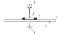
- FIG. 2 is an explanatory sectional view of the principle of creeping discharge used in the present invention.
- an application electrode 3 having a smaller surface area and a ground electrode 4 on the other surface are maintained in contact with each other on one surface of a plate-like dielectric 2 having the largest surface area.
- the application electrode 3 is electrically connected to an AC power source 5 and can supply an AC voltage to these application electrodes.
- the ground electrode 4 is grounded by connecting a ground wire 6.
- the contact area of the ground electrode 4 with the dielectric 2 is larger than the contact area of the application electrode 3 with the dielectric 2. This is the “creeping discharge body” described above.
- the creeping discharge body shown in FIG. 2 generates a low-temperature plasma discharge 7 at the edge of the application electrode 3, and the surface area of the ground electrode 4 is clearly larger than the surface area of the application electrode 3.
- the low-temperature plasma discharge 7 is only generated at the edge of the application electrode 3.
- the low-temperature plasma discharge 7 is applied to the edge of the edge at the protruding portion. It occurs on the electrode 3 side.
- the low temperature plasma discharge 7 is generated on the side of the ground electrode 4 at the edge of the end.
- This low-temperature plasma discharge on the ground side cannot be sufficiently charged because the electric charge flows to the ground, and the plasma effect of the aqueous protein solution is diminished, so it is not used as a plasma means for the aqueous protein solution in the present invention.
- the applied voltage is preferably 2 to 18 kV, and the frequency is preferably 1 to 30 kHz, and particularly preferably 3 to 10 kHz. If the frequency is less than 1 kHz, pulsed micro-discharge in the order of nanoseconds cannot be sustained, and the low-temperature plasma discharge is not stable. As a result, it is necessary to apply an extremely high voltage and it is difficult to generate the low-temperature plasma itself. Is also envisaged. On the other hand, if the frequency exceeds 30 kHz, it is difficult to supply a voltage necessary for generating a polarization electric field, and as a result, it is difficult to generate low-temperature plasma.
- these applied voltage and frequency conditions are conditions that do not take into account specific application to the present invention, and the conditions for proper implementation of the present invention are slightly different from these conditions. For example, if the frequency is too low, the voltage required for generating low-temperature plasma increases, but in the case of a mist type aqueous solution, protein combustion becomes apparent when the applied voltage becomes high.
- the atmospheric pressure for performing creeping discharge is most preferably atmospheric pressure, but it can also be lower than that.
- a special hermetic container is required, which causes problems such as a decrease in the generation efficiency of chemical species and emission of ultraviolet rays.
- a pressure vessel is required, and the generation of low-temperature plasma tends to be difficult. Therefore, it can be said that the actual benefit of carrying out the present invention in an environment other than atmospheric pressure is poor. If the range of atmospheric pressure is enumerated, it is about 0.02 MPa to atmospheric pressure.
- the thickness of the dielectric is determined according to common technical knowledge, taking into account the frequency and voltage of the AC voltage used, as well as atmospheric pressure and dielectric materials. Although it is possible to select, approximately 0.5 to 2.5 mm is preferable. In particular, when this thickness is too thin, the tendency of the dielectric to burn out is recognized. For glass, about 0.2 mm and for polymers, about 0.5 mm are exemplified as the lower limit of the thickness. On the other hand, if this thickness is too thick, the voltage required for generating low-temperature plasma increases in accordance with Paschen's law.
- the dielectric in the creeping discharge corresponds to a paraelectric having a relative dielectric constant of about 100 or less
- the materials include glass, forsterite, aluminum oxide (alumina), barium niobate, barium titanate, Examples thereof include polyvinylidene fluoride (PVDF), vinylidene fluoride-trifluoride ethylene copolymer (VDF / TrFE), vinylidene cyanide vinyl acetate copolymer (VDCN / Vac), etc., but are not limited thereto. Absent.
- the application electrode and the ground electrode may be the same or different, and metal electrodes such as an aluminum electrode, a stainless steel electrode, a copper electrode, a magnesium electrode, an iron electrode, a tungsten electrode, and a platinum electrode can be used. However, it is not limited to these. It is also possible to use an electrode in which materials are appropriately combined.
- Dielectric Barrier Discharge is a discharge form called silent discharge, ozonizer discharge, barrier discharge, dielectric barrier AC discharge, or the like.
- the dielectric barrier discharge is a discharge generated in a gap when an AC voltage is applied with a dielectric interposed between electrodes. Even if a discharge occurs, the electric charge cannot flow into the electrode due to the presence of the dielectric, and a reverse electric field is generated because the electric charge accumulates on the dielectric, so that the discharge stops in the form of glow discharge and the final discharge There is no transition to arc discharge, which is a stage. Therefore, the dielectric barrier discharge can maintain a stable and continuous discharge such as a glow discharge. In particular, the dielectric barrier discharge can stably obtain a glow-like discharge diffused even at atmospheric pressure or higher due to the presence of the dielectric.
- An apparatus for generating a dielectric barrier discharge to prepare the aqueous solution of the present invention includes an essential facility for generating a dielectric barrier discharge, specifically, an AC power source, a feeding electrode, a dielectric, And if a ground electrode is provided, a restriction
- limiting will not be recognized in particular, but it can design and produce freely according to the specific process objective.
- an AC voltage of an appropriate frequency is applied from an AC power source through a dielectric between a power supply electrode and a ground electrode, so that a glow is formed in a gap formed between these electrodes.
- the low temperature plasma discharge can be obtained.
- the frequency of the AC voltage is preferably in the order of 10 to 100 Hz to about 30 kHz, and more preferably 1 to 10 kHz. If it is smaller than the order of 10 to 100 Hz, an extremely high voltage is required for generating the low temperature plasma, and it may be difficult to generate the low temperature plasma itself. If it exceeds 30 kHz, it is difficult to generate low-temperature plasma.
- the applied voltage of the dielectric barrier discharge is several kV to several tens kV, and preferably 5 to 30 kV under atmospheric pressure.
- the atmospheric pressure in the dielectric barrier discharge is most preferably atmospheric pressure, but it can also be lower than that.
- a special hermetic container is required, which causes a problem in that the generation efficiency of chemical species is reduced and ultraviolet rays are emitted.
- dielectric barrier discharge is performed at a pressure higher than atmospheric pressure, a pressure vessel is required, and the generation of low-temperature plasma tends to be difficult. Therefore, it can be said that the actual benefit of carrying out the present invention in an environment other than atmospheric pressure is poor.
- the range of atmospheric pressure is 0.02 MPa to about atmospheric pressure.
- the “feed electrode” and the “ground electrode” may be the same or different. Specifically, the “ground electrode” of the above-described creeping discharge is used. And “applied electrode”. Further, the dielectric is the same as the creeping discharge described above.
- Aqueous solution The aqueous solution of the present invention can be prepared by bringing the aqueous solution into contact with the low-temperature plasma generated as described above and charging the solution molecules.
- the “aqueous solution” that is brought into contact with the low-temperature plasma is a solution in which protein is dissolved as a solute in an aqueous solvent mainly composed of water.
- the aqueous solvent may be water as long as the protein is easily dissolved, but depending on the type of protein, it may be slightly soluble in water. In such a case, an appropriate salt or the like should be added. In some cases, the solubility of the target protein can be improved. About what kind of salt etc. and what amount are added, it can carry out by following the conventional method according to the kind of protein to melt
- the lower limit of the protein concentration in the aqueous solution before being plasmatized is preferably about 25 ⁇ g / ml, and more preferably about 50 ⁇ g / ml. If the protein concentration is lower than 25 ⁇ g / ml, the density of protein fixation on the surface of the object will also be reduced, and it will be difficult to sufficiently exhibit the desired biocompatibility. For example, if the protein is poorly soluble in an aqueous solvent and it is difficult to ensure a large protein concentration, it is possible to compensate for the thinness of the single fixing density by performing the fixing process repeatedly. .
- the upper limit depends on the desired form of the aqueous solution of the present invention.
- the form when the form is a mist type, if the protein concentration is too high, mist formation becomes difficult, and the upper limit is about 3 mg / ml.
- the droplet type is not particularly limited, and the protein concentration can be set up to the limit of dissolution, and in many cases, it is preferably about 255 mg / ml or less.
- Proteins include peptides and also glycoproteins. Although the kind of protein to be used is not particularly limited, it is preferable to include an extracellular matrix protein. In addition, other than extracellular matrix proteins, naturally derived polyamino acids such as polylysine are also suitable.
- extracellular matrix proteins examples include proteins such as collagen, elastin, proteoglycan and glucosaminoglycan; glycoproteins such as fibronectin, laminin and vitronectin; and processed proteins such as gelatin, but are not limited thereto. Absent.
- aqueous solution of the present invention “other functional substances” can be contained.
- the functional substances include growth factors, antithrombotic factors, anticancer agents, and immunosuppressive agents.
- growth factors include growth factors, antithrombotic factors, anticancer agents, and immunosuppressive agents.
- antibodies, sugar chains, antibiotics and the like can be mentioned.
- the aqueous solution of the present invention has two modes of (1) mist type and (2) droplet type, and these modes include application conditions such as applied voltage, By controlling the protein concentration of the aqueous solution and the feed rate, it can be prepared by distinction.
- an embodiment of the apparatus of the present invention that performs creeping discharge will be disclosed with reference to the drawings, and a method for preparing an aqueous solution of the present invention using the apparatus will be described for each of these two types of embodiments.
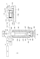
- FIG. 3 is an explanatory diagram in the case of preparing a mist type aqueous solution mainly composed of a longitudinal section in the apparatus 1 of the present invention that performs creeping discharge.
- 1) is the main body portion 10 thereof.
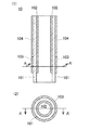
- FIG. 4B is a cross-sectional view taken along the solid line AA ′ in FIG.
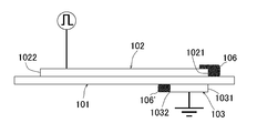
- FIG. 5 is an enlarged explanatory view of a wall section in the vicinity of the outlet 108 of the main body portion 10 where creeping discharge of the device 1 of the present invention is performed.
- the main body portion 10 includes a dielectric tube 101, an application electrode 102, and a ground electrode 103, and the application electrode 102 is in close contact with the entire inner surface except for the vicinity of the lowermost portion of the inner surface of the dielectric tube 101.
- the application electrode 102 is formed on the outer surface of the outer surface of the dielectric tube 101 so that its end does not protrude from the overlapping portion of the ground electrode 103 and the dielectric tube 101. A part of the side surface of the lower region is surrounded and brought into close contact, and is electrically grounded through the ground wire 105.
- the “protein aqueous solution introduction field” 107 is inside the cylindrical main body portion 10.
- the application electrode 102 is in contact with the atmosphere of the introduction field 107.
- the introduction place 107 is provided with a lead-out port 108 through which an atmosphere outside the introduction place 107 can be circulated.
- the outlet 108 is a cylinder port of the introduction place 107.
- the applied electrode 102 is electrically connected to an AC power source via a conductive wire 14 'or the like.
- An insulator 104 surrounds and is in close contact with the remaining upper portion of the outer surface between the dielectrics 101, and electrical insulation of the ground electrode 103 is directed toward the upper portion of the main body portion 10.
- the AC power supply is provided with a function generator 13 and an amplifier 14 and a monitor oscilloscope 15 in order to make it possible to adjust the applied voltage, frequency, etc., and each of them has conductive lines 13 ', 14', and 15 '. And are electrically connected to the application electrode 102.
- An AC voltage based on the AC power source is applied toward the application electrode 102.
- a strong electric field is formed in synchronization with the AC cycle at the edge of the portion of the application electrode 102 facing the ground electrode 103, and electrons emitted from the portion are applied to the dielectric 101.
- the opposite end 1032 of the ground electrode 103 is greatly recessed from the other end 1021 of the application electrode 102 that is clearly longer than the ground electrode 102 in the length direction of the cylinder.
- the low temperature plasma 106 is greatly generated at the edge of the end portion 1021 of the application electrode in the vicinity of the outlet 108, and a part of the low temperature plasma 106 is located on the side of the outlet 108 on the surface of the application electrode 102. Part is covered.
- the low temperature plasma 106 ' is generated at the edge of the opposite end 1032, as described above, this is not used for the plasma conversion of the protein aqueous solution.
- the sealing plug 17 is inserted on the side where the insulator 104 is provided, that is, the upper portion, and the applied electrode 102 on the inner side surface of the main body portion 10 is pressed. Sealed. Further, in the sealing plug 17, one of the arms (162) in the T-shaped hollow conduit 16 is fixed by being penetrated in a state where the pressure from the material of the sealing plug 17 is received. Of the other two arms of the conduit 16, one 161 is connected to the outer cylinder 111 of the syringe 110 of the syringe pump 11 via the conduit 114 in an airtight state, and the other is connected to the air pump 12 in an airtight state. Yes.
- the syringe pump 11 includes a syringe 110 and a support base 115.
- the syringe 110 has one end opened with a collar portion 1112 and the other end provided with a liquid lead-out portion 1111.
- the other end of the syringe 110 is kept airtight at the other end.
- An aqueous rod 1121 is provided which is slidable in the vertical direction and preferably has an inner rod 112 provided with a pressing portion 1122 at the other end.
- One end of the inner rod 112 is inserted with an appropriate amount of the solution 113.
- fixing portions 1153 and 1153 ′ of the guide rod 1152 are provided, and the push-in portion 1154 is penetrated by the guide rod 1152 and guided and supported while being movable on the rod.
- the fixing portion 1153 is provided with a recess 1155 in which the outer cylinder 111 of the syringe 110 can be placed in a stable state.
- the outer cylinder 111 of the syringe 110 is placed in the concave portion, the pressing portion 1122 at the other end of the inner rod 112 is directed to the pushing portion 1154, and the pushing portion 1154 is guided by the guide rod 1152 in the direction of arrow B.
- the aqueous solution 113 By pushing, the aqueous solution 113 can be stably led out to the conduit 114.
- the aqueous protein solution 113 before being converted into plasma enclosed in the syringe pump 11 is pushed out toward the T-shaped conduit 16 by the pressure in the direction of arrow B due to the pressing of the inner rod 112, and further The air pump 12 is pushed toward the opening 162 of the conduit 16 by the pressure in the direction of arrow C by the air pump 12.
- the aqueous protein solution 113 ′ that has been pushed into the main body 10 and has not yet been converted into plasma is fed toward the inner space of the cylindrical structure formed by the application electrode 102, and from the exposed surface of the application electrode 102.
- a desired mist-like aqueous solution 18 of the present invention is generated in contact with the low-temperature plasma 106 formed in a circular shape toward the inner space, and is discharged from the outlet 108 of the introduction field 107 to the outside.
- the preparation method of the mist type aqueous solution is performed according to the following (a) to (c) as described above.
- the frequency of the AC voltage for performing creeping discharge is 5 to 30 kHz, preferably 5 to 10 kHz. If this frequency is less than 5 kHz, the voltage value necessary for low-temperature plasma generation becomes excessively large, and the tendency of the protein itself to burn becomes strong, and if it exceeds 30 kHz, low-temperature plasma generation becomes difficult.
- the applied voltage is 2 to 8 V, preferably 2 to 4 kV. When the applied voltage is less than 2 kV, the charge becomes insufficient, and it becomes difficult to make the protein solution mist. If it exceeds 8 kV, the ratio of protein burning etc. increases as described above, and mist formation becomes inefficient.
- the protein concentration of the aqueous protein solution before being plasmatized is 25 ⁇ g / ml to 5 mg / ml, preferably 50 ⁇ g / ml to 3 mg / ml as described above.
- the pressure of the field is preferably atmospheric pressure, and the gas can be selected from air, an inert gas such as helium and argon, etc., but air is preferred.
- the thickness of the dielectric is as described above.
- the droplet type aqueous solution can be prepared by using the apparatus used for the preparation of the mist type aqueous solution described above.
- the condition (a) regarding the frequency and the applied voltage is that the range of the applied voltage is mist. Unlike the mold, it is 7.5 to 18 kV, preferably 7.5 to 16 kV.
- the reason why the lower limit value and the upper limit value of the applied voltage are specified is that the range of the applied voltage becomes higher than that of the mist type because the feed rate of (c) is larger than that of the mist type.
- the upper limit of the concentration of the protein aqueous solution before being plasmatized is not recognized as in the mist type, and the upper limit is about 255 mg / ml. .
- the feed rate of the aqueous protein solution before the plasma conversion of (c) is 36 to 180 mm / min.
- Cells or cell masses that are subject to cell production by carrying out the production method of the present invention are not particularly limited, and examples include prokaryotic cells, eukaryotic cells, and modified cells derived from these cells. Stem cells Even that is possible. Not only one type but also a combination of two or more types of cells may be used.
- the method of “adhesion of the aqueous solution of the present invention to the surface of a plurality of cells or cell clusters” described above is not particularly limited, and can be freely selected according to the mode and purpose of immobilizing a plurality of cells. it can.
- the aqueous solution is a mist type
- spraying on the surface of a cell or a cell mass, contact with a mist atmosphere, etc. may be mentioned.
- contact with the mist atmosphere accompanied by the movement of the cell or cell mass can also be performed.
- examples include pouring onto the surface of a cell or cell mass, immersion of the cell or cell mass in an aqueous solution, application of an aqueous solution to the cell or cell mass surface, and the like.
- the aqueous solution of the present invention has extremely low surface tension due to the charging of the constituent molecules by low-temperature plasma, and the aqueous solution can be easily and evenly attached to the cell surface by contact. .
- the standard of the amount of contact per time depends on the protein concentration of the aqueous solution of the present invention, but in the case of the mist type, it is set so that the remaining amount of the aqueous solution per unit area of the contact surface is 2 ⁇ l / cm 2 or more. It is preferable to do. In the case of the droplet type, it is preferable to set the residual amount of the aqueous solution per unit area of the contact surface of 48 ⁇ l / cm 2 or more.
- these processes are preferably performed in an environment where the cells continue to be utilized. Therefore, these processes are performed in a short time without drying the cells, and then the produced cell fixed product is subjected to cell survival conditions, preferably cell culture conditions, or cryopreservation conditions. It is preferable to maintain the viability of the cells underneath.
- the use of the cell fixed product obtained by the production method of the present invention is not particularly limited.
- it can be used for practical use and research in the medical field, the food industry field, and the like.
- the present invention can be applied to specific cells and used as a cell fixed product.
- cardiomyocytes, blood vessel-derived cells, muscle-derived cells, epithelial cells, epidermal cells, endothelial cells, mesothelial cells, hepatocytes, cornea-derived cells, etc. using the production method of the present invention, in sheet form, After immobilization so as to form a lump or the like, it can be used for a desired use as the cell fixed product of the present invention.
- endothelial cells the following examples are given with a focus on vascular endothelial cells, but are not limited thereto.
- the cells or cells constituting the cell mass used in the production method of the present invention are not particularly limited, and may be unicellular organisms themselves or separated from multicellular organisms. It is possible to select freely according to the purpose that contributes to practical use and research in the medical field and the food industry field described later. It may be a eukaryotic unicellular organism or a eukaryotic multicellular organism cell or a prokaryotic cell. In addition, for example, even cells and cell lines directly isolated from living organisms, stem cells [ES cells (embryonic stem cells) and iPS cells (induced pluripotent stem cells)], are induced after the stem cells are induced. It may be a differentiated cell or a cell transformed by gene transfer.
- ES cells embryonic stem cells
- iPS cells induced pluripotent stem cells
- the human cells to which the present invention is applied are not particularly limited. For example, if only epithelial cells or epidermal cells originally having strong adhesion ability are used. In addition, endothelial cells having weak adhesive strength can also be applied.
- endothelial cells examples include umbilical vein endothelial cells, coronary artery endothelial cells, saphenous vein endothelial cells, pulmonary vein endothelial cells, pulmonary artery endothelial cells, aortic endothelial cells, skin vascular endothelial cells, bladder microvascular endothelial cells, Cardiac microvascular endothelial cells, cutaneous microlymphatic endothelial cells, mesenteric vascular endothelial cells, kidney glomerular endothelial cells, lymphatic endothelial cells, breast microvascular endothelial cells, ovarian microvascular endothelial cells, placental microvascular endothelial cells, prostate Examples thereof include vascular endothelial cells such as microvascular endothelial cells, retinal microvascular endothelial cells, small intestine microvascular endothelial cells, thyroid vascular endothelial cells, and sinusoidal endothelial cells;
- both the application electrode 102 and the ground electrode 103 are made of aluminum sheet tape (thickness 90 ⁇ m) on the glass tube wall surface with a metal rod. It was extended and used for rubbing. Therefore, the inner diameter of the tube considering the thickness of the application electrode 103 is also approximated to 6 mm (the same applies hereinafter).
- the main body 10 was constructed using an insulating tape (Kapton (registered trademark) / polyimide tape: Toray DuPont) as the insulator 104.
- a glass tube was used as the T-shaped conduit 16, and a rubber plug was used as the sealing plug 17.
- a low-temperature plasma generator was produced.
- a peak voltage of 8 kV and a frequency of 5 kHz are applied to the application electrode of the apparatus described above, and the ground electrode 103 of the main body portion of the low-temperature plasma generator is in contact with the dielectric 101.
- a creeping discharge on the inner peripheral surface of the applied electrode 102 corresponding to the area is performed to generate a low-temperature plasma, and a collagen-containing aqueous solution [3 mg / ml collagen aqueous solution (Thermo Scientific) per 1 ml of the aqueous solution] 0.17 ml of 10-fold concentration Medium 199 (Thermo Scientific), 0.017 ml of 1 mol / l sodium hydroxide aqueous solution (Wako Pure Chemical Industries), and 0.213 ml of ultrapure water
- To the main body via a T-shaped conduit by pressing with a syringe pump Min was flowed by feeding, in contact with the low-temperature plasma, were prepared of the protein aqueous solution of the present invention the droplet type.
- the surface area of the creeping discharge body that generates low-temperature plasma was approximated as the contact area of the ground electrode 103 with respect to the dielectric 101 and was 94 mm 2 .
- the upper layer is (i) Madin-Darby canine kidney cells; MDCK cell, dog kidney renal tubular epithelial cell line (Tohoku University Institute of Aging Medicine, Medical Cell Resource Center, Cell (Bank) and the lower layer were constructed as (ii) human umbilical vein endothelial cells (HUVECs (Cell Applications)).
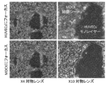
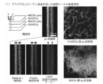
- FIG. 7 shows a photomicrograph image representing the state of a system using a collagen aqueous solution that has been subjected to the droplet-type plasma treatment after incubation at 37 ° C. for 30 minutes on a gelatin-coated plastic dish. It is the photograph of the space
- the other part was entirely covered with MDCK cells.
- the upper two photos (4x on the left and 10x on the right) focus on HUVECs cells, and the two lower photos (4x on the left and 10x on the right) focus on MDCK cells. . It can be seen that both cells are firmly adhered to each other.
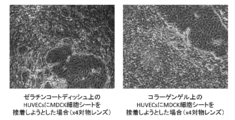
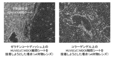
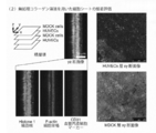
- FIG. 8 (1) shows a microscopic image of a four-fold gap after the above-described cultivation with droplet-type plasma-treated collagen. The left figure is the microscopic image on the gelatin-coated plastic dish, and the right figure is the microscopic image on the collagen gel.
- FIG. 8 (2) shows a microscopic image of a four-fold gap after the above culture with untreated collagen.
- the left figure is the microscopic image on the gelatin-coated plastic dish, and the right figure is the microscopic image on the collagen gel.
- HUVECs cells which are originally endothelial cells with weak adhesive strength, are used.
- stable cell adhesion with a good yield is recognized by the present invention.
- the usefulness of the present invention has been clarified.
- an untreated collagen solution or a collagen solution that has undergone a droplet-type plasma treatment is applied as an adhesive between each cell sheet layer. 250 ⁇ l was applied from the top of each cell sheet.
- the four-layer heterogeneous cell sheet is cultured for 24 hours in the above-described culture medium for HUVECs cells, and then using 4% paraformaldehyde / phosphate buffer (Wako Pure Chemical Industries, Ltd.). Fixing treatment (30 minutes standing, room temperature) was performed.
- FIG. 9 shows the results when a collagen aqueous solution subjected to a droplet type plasma treatment is used, and the results using untreated collagen.
- FIG. 9 (1) shows the result in the system using plasma collagen
- FIG. 9 (2) shows the result in the system using untreated collagen.
- the plasma-treated collagen of the present invention as a cell adhesion liquid, cells of any combination can be easily adhered to each other even if cells with inherently low adhesion such as endothelial cells are included. It turns out that it will be possible. Further, it is obvious that this is not only the sheet type but also other forms such as hetero-type cell clusters.
- Dielectric tube 102 Application electrode 1021: End portion on the outlet side of the application electrode 1022: End portion on the non-outlet port side of the application electrode 103: Ground electrode 1031: Conduction of the ground electrode End portion 1032 on the outlet side: End portion 104 on the non-outlet side of the ground electrode 104: Insulator 105: Ground wire 106: Low temperature plasma discharge 106 ′: Low temperature plasma discharge 107 on the ground electrode side 107: Introduction site 108 of the protein aqueous solution: Outlet 11: Syringe pump 110: Syringe 111: Outer tube 1111: Liquid outlet 1111: Collar 112: Internal rod 1121: Sliding body 1 22: pressing portion 113, 113 ': an aqueous solution before
Landscapes
- Life Sciences & Earth Sciences (AREA)
- Chemical & Material Sciences (AREA)
- Engineering & Computer Science (AREA)
- Health & Medical Sciences (AREA)
- Genetics & Genomics (AREA)
- Biotechnology (AREA)
- Organic Chemistry (AREA)
- Zoology (AREA)
- Bioinformatics & Cheminformatics (AREA)
- Wood Science & Technology (AREA)
- Medicinal Chemistry (AREA)
- Microbiology (AREA)
- Biomedical Technology (AREA)
- Virology (AREA)
- Biochemistry (AREA)
- General Engineering & Computer Science (AREA)
- General Health & Medical Sciences (AREA)
- Tropical Medicine & Parasitology (AREA)
- Micro-Organisms Or Cultivation Processes Thereof (AREA)
- Materials For Medical Uses (AREA)
- Peptides Or Proteins (AREA)
- Apparatus Associated With Microorganisms And Enzymes (AREA)
Abstract
細胞又は細胞塊同士を細胞外マトリックスタンパク質等のタンパク質で接着させて、細胞同士の集合固定物を生産する手段を見出し、様々な応用に資することを目的とするものである。具体的には、好ましくは沿面放電による低温プラズマ放電装置を用いて、細胞外マトリックスタンパク質に対して低温プラズマ放電によるプラズマ化を行い、これにより得られたプラズマ化タンパク質水性溶液を、ミスト又は液滴として、細胞又は細胞塊同士の接着液として用いることにより、これらの細胞の集合固定物を得ることが可能であることを見出し、本発明を完成した。
Description
本発明は、人為的な手段を施して得られる細胞調製物に関する発明であり、さらに具体的には、低温プラズマ放電により調製されるタンパク質水性溶液を用いる、細胞の集合固定物の生産方法、及び、当該生産方法にて生産される細胞の集合固定物に関する発明である。
細胞接着技術は、医療関連技術をはじめ、様々な分野でその重要性を増している。
特に生きた状態の複数の細胞を固定化することにより、様々な応用に向けての可能性が認められる。
例えば、ヒトを含め多細胞生物では、細胞は個々のみならず多細胞の集合体として様々な機能を発揮していることが知られており、この事実を利用した多細胞の集合体を薬剤の効能の試験に用いる試みがなされている。
再生医療分野では、「細胞シート」に関する技術が大きく期待されている。
細胞シート技術としては、角膜上皮幹細胞疲弊症の細胞シートによる角膜再生治療(非特許文献1)が知られており、この場合は1枚の角膜上皮細胞シートを患部に貼り付けるだけで角膜実質層に接着させることが可能である。
この他にも、心筋、歯周、軟骨等を対象にした臨床研究が行われており(非特許文献2、3)、特に近年ヒトiPS細胞を高効率に心筋細胞へ分化させる培養手法が確立され、ヒト心筋細胞シートを用いた基礎研究が行われている(非特許文献4)。
Nishida K, et al., N Engl J Med, 351: 1187-1196, 2004
Haraguchi Y, et al., Stem Cells Transl Med, 1 : 136-141, 2012
Iwata T, et al., J Tissue Eng Regen Med, in press(2015)
Masuura K, et al., Biochem BiophysRes Commun, 425 : 321-327, 2012
本発明は、細胞又は細胞塊同士を細胞外マトリックスタンパク質等のタンパク質で接着させて、細胞同士の固定物を生産する手段を見出し、様々な応用に資することを目的とするものである。
本発明者らは上記の課題について検討を行い、タンパク質を含有する水性溶液を低温プラズマ放電によるプラズマ化を行うことによって得られるタンパク質水性溶液を、細胞又は細胞塊同士を接着液として用いることにより、驚くべきことに細胞又は細胞塊同士が生きた状態で接着した細胞固定物を生産することが可能であることを見出して、本発明を完成した。
すなわち本発明は、低温プラズマ放電によりプラズマ化がなされているタンパク質水性溶液(以下、本発明の水性溶液ともいう)を、複数個の細胞又は細胞塊の表面に付着させた状態で、各々の細胞又は細胞塊同士を接触させることにより、これらの細胞又は細胞塊同士をタンパク質水性溶液の内容成分を介して接着させて集合固定物化することを特徴とする、複数細胞の集合固定物の生産方法(以下、本発明の生産方法ともいう)を提供する発明であり、さらに本発明の生産方法を行うことにより生産されることを特徴とする複数細胞の集合固定物(以下、本発明の細胞固定物ともいう)を提供する発明である。なお、本発明の細胞固定物は、上記のように「生きた状態の細胞」の固定物とすることが可能であるが、それ以外の場合、具体的には「生きていない(死んだ)状態の細胞」を固定することも勿論可能であり、本発明の生産方法で接着させる「細胞又は細胞塊」、及び、本発明の細胞固定物を構成する「細胞」は、生きている細胞であっても、死んだ細胞であってもよい。死んだ細胞には、例えば、分離された細胞核等の細胞分離物も含まれる。
上記の細胞又は細胞塊は、特に限定されず、単細胞生物そのものであっても良く、多細胞生物から分離されたものであっても良く、後述する医療分野や食品工業分野等の実用や研究に資する目的に応じて自由に選択することが可能である。真核単細胞生物又は真核多細胞生物細胞であっても、原核生物細胞であってもよい。
上記の複数個の細胞又は細胞塊は、同一種の細胞であっても良いが、2種以上の細胞、又は、複数個の細胞塊は構成細胞が異なる2種以上の細胞塊とすることが可能であり、特に本発明は、2種以上の細胞や細胞塊を組み合わせて接着対象とすることが容易に可能である点が優れている。
また、接着対象として選択される細胞種又は細胞塊の構成細胞として、元々接着能力が優れる上皮細胞又は表皮細胞とすることも可能であるが、強い接着能力が認められない内皮細胞とすることも可能であり、これらを組み合わせることも可能である。
すなわち、本発明の生産方法として、複数個の細胞、又は、複数個の細胞塊であって構成細胞が異なる2種以上の細胞塊に、上皮細胞又は表皮細胞が含まれている態様が認められ、これとは別個に又は組み合わさって、内皮細胞が含まれている態様が認められる。
また、細胞塊の好適な態様として「細胞シート」が挙げられる。この場合生産される複数細胞の集合固定物は、複数の細胞シート同士がシート面にて接着されている積層細胞シートが典型例である。積層される単位となる細胞シートは互いに同一の細胞で構成されていても、異なる細胞で構成されていてもよい。また、積層数は、2以上で必要に応じて適宜設定することができる。
低温プラズマ放電には、沿面放電と誘電体バリア放電が含まれるが、本発明では沿面放電が好適である。
本発明者らは、上記の本発明の水性溶液の調製において、特にこれに適した沿面放電装置を作製した。沿面放電は、一般的に「誘電体を挟んで印加電極と誘導電極が存在する場合に、印加電極から誘電体に沿ってなされる放電現象」として知られている。
本発明の水性溶液に含有されるタンパク質は、細胞外マトリックスタンパク質を含むことが好適である。また、本発明の水性溶液中には、他の機能性物質を含有させることも可能である。当該機能性物質は、具体的な目的に応じて適宜選択されるべきものであり特に限定されないが、例えば、増殖因子、抗血栓因子、抗がん剤、免疫抑制剤、抗体、糖鎖、抗生物質等が挙げられる。
本発明の水性溶液には、(1)当該水性溶液がミスト化されている「ミスト型」、及び、(2)当該水性溶液が液滴である「液滴型」、の2通りの態様が有り、それぞれの態様の調製方法は異なっている。また、(3)本発明の水性溶液の調製を行うのに好適な沿面放電装置(本発明の装置)についての記載も行う。
ミスト型の水性溶液は、タンパク質水性溶液が低温プラズマ放電に接することにより、水に包まれたタンパク質分子の周りに過剰な電荷が供給され、電荷同士の反発力によって非常に細かい粒子(数十nm~数百nm程度の径)に弾けてミスト化した状態であると考えられる。ミスト型の水性溶液のイメージ図を図1(1)に示した。
液滴型の水性溶液は、タンパク質分子を含有する水溶液中に、低温プラズマ放電により過剰に電荷が供給された状態であると考えられる。液滴型の水性溶液のイメージを図1(2)に示した。
本発明の生産方法においては両形態の本発明の水性溶液を接着液として用いることができるが、「液滴型」の方が、一般的に接着作業が簡便である。
(1)ミスト型の水性溶液の調製
ミスト型の水性溶液の調製は、プラズマ化がなされる前のタンパク質水性溶液を、特定の送り速度で沿面放電による低温プラズマに接触させることにより、当該タンパク質、又は、当該タンパク質と他の機能性物質の分子を荷電化することによって、当該分子同士を反発させるプラズマミスト化を、下記(a)~(c)に従い行うことを特徴とする。
(a) 上記の沿面放電を行うための交流電圧の周波数は5~30kHz、印加電圧は2~4kVである。
(b) 上記のプラズマ化がなされる前のタンパク質水性溶液のタンパク質濃度は、25μg/ml~5mg/mlである。
(c) 上記のプラズマ化がなされる前のタンパク質水性溶液の特定の送り速度は、3.0~36mm/分である。
この送り速度単位である「mm/分」は、「単位時間当たりのタンパク質水性溶液の送り容積(μl又はmm3/分)」を、「タンパク質水性溶液の導入場(後述)の当該水性溶液の進行方向に対して垂直方向の断面積(mm2)」で割って算出される値である。よって、この「送り速度」と「当該断面積」から、「単位時間当たりのタンパク質水性溶液の送り容積」を算出することも容易に可能である。
ミスト型の水性溶液の調製における沿面放電の手段としては、後述する本発明の装置が好適である。この場合、タンパク質水性溶液の荷電化の場として用いられる導入場(後述)の、当該水性溶液の進行方向に対して垂直方向の断面積は、タンパク質水性溶液が歩留まり良くチャージされるために、好適な上限が定められる。例えば、当該導入場の形状が筒状の場合には、当該断面積は30mm2以下であることが好適である。この筒状態様の場合の当該断面積の下限は特に限定されないが、1mm2程度が好適である。また、当該導入場が、向かい合った板状の沿面放電体の間隙からなる場合は、当該向かい合った沿面放電体の印加電極板間の距離は6mm以下であることが好適であり、下限は特に限定されないが0.5mm程度であることが好適である。
沿面放電の発生機構である沿面放電体(後述)の印加電極と接地電極が重なり合っている部分の表面積も同様に、タンパク質水性溶液が歩留まり良くチャージされるために、ある程度は確保されていることが好適である。具体的には、タンパク質水性溶液の導入場の形状が筒状である場合は、上記断面積に対して好適には3~30倍、特に好適には3~10倍の当該表面積である。当該導入場が、向かい合った板状の沿面放電体の間隙からなる場合は、上記印加電極板間の距離に、好適には3~30倍、特に好適には3~10倍の距離を乗じて算出される表面積であることが好適である。
(2)液滴型の水性溶液の調製
液滴型の水性溶液の調製は、プラズマ化がなされる前のタンパク質水性溶液を、特定の送り速度で沿面放電による低温プラズマに接触させることにより、当該タンパク質、又は、当該タンパク質と他の機能性物質の分子の荷電化を、下記(a)~(c)に従い行うことを特徴とする。
(a) 上記の沿面放電を行うための交流電圧の周波数は5~30kHz、印加電圧は7.5~18kVである。
(b) 上記のプラズマ化がなされる前のタンパク質水性溶液のタンパク質濃度は、25μg/ml~255mg/mlである。
(c) 上記のプラズマ化がなされる前のタンパク質水性溶液の特定の送り速度は、36~180mm/分である。
液滴型の水性溶液の調製は、プラズマ化がなされる前のタンパク質水性溶液を、特定の送り速度で沿面放電による低温プラズマに接触させることにより、当該タンパク質、又は、当該タンパク質と他の機能性物質の分子の荷電化を、下記(a)~(c)に従い行うことを特徴とする。
(a) 上記の沿面放電を行うための交流電圧の周波数は5~30kHz、印加電圧は7.5~18kVである。
(b) 上記のプラズマ化がなされる前のタンパク質水性溶液のタンパク質濃度は、25μg/ml~255mg/mlである。
(c) 上記のプラズマ化がなされる前のタンパク質水性溶液の特定の送り速度は、36~180mm/分である。
液滴型の水性溶液の調製における沿面放電の手段としても、後述する本発明の装置が好適である。この場合、タンパク質水性溶液の荷電化の場として用いられる導入場(後述)の、当該水性溶液の進行方向に対して垂直方向の断面積は、タンパク質水性溶液が歩留まり良くチャージされるために、好適な上限が定められる。例えば、当該導入場の形状が筒状の場合には、当該断面積は30mm2以下であることが好適である。この筒状態様の場合の当該断面積の下限は特に限定されないが、1mm2程度が好適である。また、当該導入場が、向かい合った板状の沿面放電体の間隙からなる場合は、当該向かい合った沿面放電体の印加電極板間の距離は6mm以下であることが好適であり、下限は特に限定されないが0.5mm程度であることが好適である。
沿面放電の発生機構である沿面放電体(後述)の印加電極と接地電極が重なり合っている部分の表面積も同様に、タンパク質水性溶液が歩留まり良くチャージされるために、ある程度は確保されていることが好適である。具体的には、タンパク質水性溶液の導入場の形状が筒状である場合は、上記断面積に対して好適には3~30倍、特に好適には3~10倍の当該表面積である。当該導入場が、向かい合った板状の沿面放電体の間隙からなる場合は、上記印加電極板間の距離に、好適には3~30倍、特に好適には3~10倍の距離を乗じて算出される表面積であることが好適である。
(3)本発明の装置
前述の本発明の装置は、タンパク質水性溶液の導入場が設けられ、当該導入場においてタンパク質水性溶液に沿面放電体から発生する低温プラズマ放電を作用させることにより、プラズマ化したタンパク質を生成するための沿面放電装置であって、当該沿面放電体は、面状の誘電体の表裏の一方において印加電極が、他方において接地電極がそれぞれ当該誘電体と接触状態で設けられており、当該誘電体の面上の当該印加電極の端部と当該接地電極の端部の一部又は全部が揃っているか、あるいは、当該接地電極の端部が当該印加電極の端部の一部又は全部からはみ出すように設けられている沿面放電体であって、当該沿面放電体の1個又は2個以上が、タンパク質水性溶液の導入場の雰囲気に対する接触面を印加電極面として設けられていることを特徴とする、沿面放電装置である。なお、「沿面放電体から発生する低温プラズマ放電」は、性質的には「誘電体バリア放電」と同様の低温プラズマ放電(大気圧で電子温度のみが高い非平衡プラズマ(後述))である。
前述の本発明の装置は、タンパク質水性溶液の導入場が設けられ、当該導入場においてタンパク質水性溶液に沿面放電体から発生する低温プラズマ放電を作用させることにより、プラズマ化したタンパク質を生成するための沿面放電装置であって、当該沿面放電体は、面状の誘電体の表裏の一方において印加電極が、他方において接地電極がそれぞれ当該誘電体と接触状態で設けられており、当該誘電体の面上の当該印加電極の端部と当該接地電極の端部の一部又は全部が揃っているか、あるいは、当該接地電極の端部が当該印加電極の端部の一部又は全部からはみ出すように設けられている沿面放電体であって、当該沿面放電体の1個又は2個以上が、タンパク質水性溶液の導入場の雰囲気に対する接触面を印加電極面として設けられていることを特徴とする、沿面放電装置である。なお、「沿面放電体から発生する低温プラズマ放電」は、性質的には「誘電体バリア放電」と同様の低温プラズマ放電(大気圧で電子温度のみが高い非平衡プラズマ(後述))である。
上記した「タンパク質水性溶液の導入場」とは、プラズマ化がなされる前のタンパク質水性溶液に、沿面放電体から発生する低温プラズマ放電を作用させるための場である。当該作用を行う前提として、プラズマ化がなされる前のタンパク質溶液を当該場に導入する必要がある。「導入」とは、当該場にプラズマ化がなされる前のタンパク質溶液を入れる行為であり、具体的な手段を問わず、例えば、進入、注入等を含む。「タンパク質水性溶液の導入場」の構造は、導入されたプラズマ化がなされる前のタンパク質水性溶液に対して、沿面放電による低温プラズマ放電を作用させることができる構造である限り、特に限定されないが、プラズマ化がなされる前のタンパク質水性溶液を導入するための「導入口」と、プラズマ化したタンパク質を導出するための「導出口」が設けられていることが好適である。具体的な形状としては、筒状、中空平板状(当該導入場が、向かい合った板状の沿面放電体の間隙からなる)、ハニカム状、中空積層板状が例示できるが、筒状が好適である。筒状は、円筒状、多角筒状を含み、複数の筒状単位の長さ方向が揃った集合筒(ハニカム状等)であってもよいが、特に円筒状であることが好適である。
「沿面放電体」は、「タンパク質水性溶液の導入場」の雰囲気に対して沿面放電作用により低温プラズマ放電を行う単位である。具体的には、当該沿面放電体は、面状の誘電体の表裏の一方において印加電極が、他方において接地電極がそれぞれ当該誘電体と接触状態で設けられており、当該誘電体の面上の当該印加電極の端部と当該接地電極の端部の一部又は全部が揃っているか、あるいは、当該接地電極の端部が当該印加電極の端部の一部又は全部からはみ出すように設けられていることを特徴とする、沿面放電を行う単位である。沿面放電は、この「揃っているか、又は、はみ出している端部の沿面の印加電極側」において発生する。以下、この印加電極側への沿面放電が行われる領域を「沿面放電部」ともいう。後述するように、印加電極側が接地電極側よりもはみ出している領域では、接地側に沿面放電が発生するが、この領域は「沿面放電部」からは除外される。誘電体の形状を示す「面状」とは、平面状であっても、曲面状であってもよい。曲面は、円柱曲面等の柱曲面、錐面等の可展面、球曲面、回転面等、特に限定されない。印加電極と接地電極がこのような誘電体の表裏にそれぞれ接触状態で設けられて、「沿面放電体」が構成される。
上記のように「沿面放電体」においては、面状の誘電体の表裏の一方において印加電極が、他方において接地電極がそれぞれ当該誘電体と接触状態で設けられており、当該誘電体の面上の当該印加電極の端部と当該接地電極の端部の一部又は全部が揃っているか、あるいは、当該接地電極の端部が当該印加電極の端部の一部又は全部からはみ出すように設けられている。「印加電極と接地電極の端部と接地電極の端部が揃っているか、又は、接地電極の端部がはみ出している」における「はみ出し」の程度、すなわち、「接地電極端部が印加電極端部からはみ出す距離」は特に限定されず、本発明の装置における「タンパク質水性溶液の導入場」の形状等に応じて自由に設定できるが、一般的には当該距離をdとすると、好ましくは0<d≦5mm、特に好ましくは0<d≦1mm(d=0は、端部が揃っている場合)である。ただし、dが5mmを超えて、10mmや20mm、さらにそれ以上であっても「沿面放電による低温プラズマの発生」という機能を発揮させることは可能である。このような沿面放電体の接地電極端部と印加電極端部が揃っているか、又は、接地電極端部がはみ出している「沿面放電体端部」において、「端部が揃っている、又は、接地電極端部がはみ出している」割合は、100%であることが最も好ましいが、設計等によっては80%程度でも実用的であり、好適範囲内である。
1個又は2個以上の「沿面放電体」の印加電極面が、「タンパク質水性溶液の導入場」の雰囲気と接触する面である。当該導入場の雰囲気に接するように設けられる「沿面放電体」の数は、自由に設計することができる。「沿面放電体」の数を増減することによって、沿面放電による低温プラズマの発生箇所を、「タンパク質水性溶液の導入場」内において増減することができる。
例えば、タンパク質水性溶液の導入場が筒状体の内部となっており、「沿面放電体」の1個又は2個以上が当該筒状体の全部又は一部を構成する態様が挙げられる。「沿面放電体」が1個の態様については後述する。例えば、筒状の誘電体の筒側面の2箇所以上に、印加電極(筒の内側)と接地電極(筒の外側)を接触状態で、上記の端部における条件を満たした状態で相対して設けることにより、2個以上の沿面放電体が設けられた、筒内部をタンパク質水性溶液の導入場とする筒状構造の本発明の装置を構成することができる。当該2個以上の沿面放電体の配置としては、例えば、筒状体の長さ方向(両開口部を結ぶ方向)に間隔を設けて、複数の長さの短い筒状の沿面放電体を設けること等が挙げられるが、これに限定されるものではない。また、単一の沿面放電体の中に複数箇所の沿面放電部を設けることも可能である。
なお、「タンパク質水性溶液の導入場」を構成する一部を誘電体とする場合は、当該誘電体以外の構造部分は、絶縁物質であるか、又は、絶縁処理が施されることで、電気的に絶縁状態が保たれていなければならない。本発明の装置の誘電体の内側面又は印加電極が形成する筒状構造の内側空間に向けての送液機構が設けられていることが好適である。
前述のように、本発明の水性溶液の調製において、本発明の装置を沿面放電手段として用い、かつ、当該沿面放電装置の「タンパク質水性溶液の導入場」に向けて、プラズマ化がなされる前のタンパク質水性溶液を特定の送り速度で送液して、当該導入場の内部に発生させた沿面放電の低温プラズマと接触させることにより、本発明の水性溶液の調製を効率的に行うことができる。この処理前のタンパク質水性溶液の送りは、上記の送液機構を介して行うことが好適である。
本発明により、細胞又は細胞塊同士を効率的に、かつ、歩留まり良く接着する手段が提供される。本発明の生産方法は、本来接着性に乏しい内皮細胞等であっても、さらに細胞の培養環境を問わずに同種又は異種の細胞同士を、容易に生きたまま接着させて維持することが可能であり、例えば、細胞シートでは、同種又は異種の細胞からなる細胞シート同士を接着させて積層化することも容易である。また、後述する実施例に示す簡便な細胞シートの作成方法(例えば、Kikuchi, T. et al.: Biomaterials, 35, 2428 (2014))との組み合わせが容易であり、多種細胞に対して同時に3次元共培養を行うことが必要な従来の3次元培養法等よりも短時間に接着工程を行うことが可能である。すなわち、本発明においては細胞間接着が容易であることから、細胞の接着を行うまでは、単一種の細胞をシート状や塊状に培養すれば良く、競合可能性のある異なる細胞の共培養を行う必要が無くなり、前提となる培養作業も簡便に済ませることができる。本発明により、同種又は異種の細胞からなる細胞シート等の細胞固定物を自在に生産する途が提供され、再生医療分野や食品工業分野における貢献は多大である。
本発明の生産方法において、内皮細胞等の本来接着力が弱い細胞までも、細胞接着が極めて容易になる理由は、必ずしも明らかではない。敢えて推測すれば、過剰に荷電されたコラーゲン等の細胞外マトリックスタンパク質を含有する水性溶液の上に細胞シートや細胞塊を載置することで、細胞の足場が結合しやすくなるためとも考えられる。細胞は足場である焦点接着斑構成タンパク質のインテグリン(膜貫通タンパク質)を介して、細胞外マトリックスタンパク質と接着しており、このインテグリンと細胞外マトリックスは静電気的に結合しているため、これにプラズマ化したタンパク質水性溶液が影響を与えることが考えられる。また、負電荷を有する細胞を、タンパク質水性溶液中の荷電したタンパク質が静電気的に引き寄せることで、接着性をあげていることも考えられる。
[本発明の水性溶液]
本発明の水性溶液は、タンパク質水性溶液が低温プラズマ放電によりプラズマ化がなされたプラズマ化水性溶液である。
本発明の水性溶液は、タンパク質水性溶液が低温プラズマ放電によりプラズマ化がなされたプラズマ化水性溶液である。
(1)低温プラズマ
既に言及している「低温プラズマ」とは、電子温度(Te)が気体温度(Tg)よりも明らかに大きく(Te/Tg>100)、TeとTgとが平衡に達していないプラズマであり、別名で非平衡プラズマとして知られている。低温プラズマ放電とは、この低温プラズマを得るための放電であり、グロー放電、コロナ放電、誘電体バリア放電、沿面放電等が該当する。これらの中でも、沿面放電又は誘電体バリア放電を用いることが好ましい。
既に言及している「低温プラズマ」とは、電子温度(Te)が気体温度(Tg)よりも明らかに大きく(Te/Tg>100)、TeとTgとが平衡に達していないプラズマであり、別名で非平衡プラズマとして知られている。低温プラズマ放電とは、この低温プラズマを得るための放電であり、グロー放電、コロナ放電、誘電体バリア放電、沿面放電等が該当する。これらの中でも、沿面放電又は誘電体バリア放電を用いることが好ましい。
(1)-1:沿面放電
沿面放電においては、交流電源から適切な周波数の交流電圧を、印加電極に印加することにより、印加電極において交流周期に同期して強い電界が形成され、当該電界から放出された電子が誘電体の表面に付与される現象と、それらが再び印加電極に戻る現象が繰り返し起こることによりグロー状の低温プラズマ放電を得ることができる。
沿面放電においては、交流電源から適切な周波数の交流電圧を、印加電極に印加することにより、印加電極において交流周期に同期して強い電界が形成され、当該電界から放出された電子が誘電体の表面に付与される現象と、それらが再び印加電極に戻る現象が繰り返し起こることによりグロー状の低温プラズマ放電を得ることができる。
沿面放電を発生させて、本発明の水性溶液を調製するための装置は、沿面放電を発生させるための本質的な設備、具体的には、交流電源、接地電極、誘電体、及び、印加電極が備わっていれば特に制限は認められず、具体的な処理目的に応じて自由に設計し、作製することができる。接地電極、誘電体、及び、印加電極は、互いに接しており、印加電極に交流電源から給電がなされ、接地電極にはアース線が接続されて接地がなされている。
図2は、本発明で用いる沿面放電の原理の説明断面図である。この図面において、最も大きな面面積を有する板状の誘電体2の一方の面に、それよりも面面積の小さな、印加電極3と、他方の面に同接地電極4が、共に接触状態で維持されている。印加電極3は、交流電源5と電気的に接続されており、交流電圧をこれらの印加電極に供給可能である。接地電極4は、アース線6が接続されて接地がなされている。図2に示した沿面放電では、接地電極4の誘電体2との接触面積の方が、印加電極3の誘電体2との接触面積よりも大きい。これが、上記の「沿面放電体」である。
図2に示す沿面放電体は、印加電極3の辺縁部に低温プラズマ放電7を生成するもので、接地電極4の面面積が印加電極3の面面積よりも明らかに大きくなっているが、あくまでも低温プラズマ放電7は、印加電極3の辺縁部において発生する。上述したように、接地電極4と印加電極3の端部が重なり合っている場合と、接地電極4がはみ出している場合、当該はみ出し部分においては、低温プラズマ放電7は当該端部の辺縁の印加電極3側に発生する。逆に、印加電極3が接地電極4の端部からはみ出している部分においては、低温プラズマ放電7は当該端部の辺縁の接地電極4側に発生する。この接地側の低温プラズマ放電は、電荷が接地に流れてしまうため十分な荷電を行えず、タンパク質水性溶液のプラズマ化効果が薄れるので、本発明におけるタンパク質水性溶液に対するプラズマ化手段としては用いない。
図2に示すような本発明で用いる沿面放電を行う場合の印加電圧として2~18kV、周波数は1~30kHzが好適であり、特に3~10kHzが好適である。周波数が1kHz未満であるとナノ秒オーダーのパルス性のマイクロ放電が持続出来ずに低温プラズマ放電が安定せず、結果として極度に高い電圧をかける必要があり、低温プラズマ自体の生成が困難な場合も想定される。また、30kHzを超えると、分極電界生成に至るまでに十分に必要な電圧の供給をさせ難くなり、その結果として低温プラズマの生成は困難となる。ただし、これらの印加電圧と周波数の条件は、あくまでも本発明への具体的な適用を考慮しない条件であり、本発明の適切な実施のための条件は、これらの条件とは若干異なっている。例えば、周波数が低すぎると低温プラズマ発生のために要求される電圧は高くなるが、特にミスト型の水性溶液の場合は印加電圧が高電圧になるとタンパク質の燃焼が顕在化してくる。
また、沿面放電を行うための気圧は、大気圧が最も好適であるが、それより低い気圧下でも可能である。ただし、大気圧より低い気圧で沿面放電を行う場合には、特殊な密閉容器が必要であり、化学種の生成効率の低下、紫外線の放出が問題となる。大気圧より高い気圧で沿面放電を行う場合には、圧力容器が必要であり、低温プラズマの生成自体が困難となる傾向がある。よって、大気圧以外の環境下において本発明を行う実益は乏しいといえる。あえて気圧の範囲を挙げれば、0.02MPa~大気圧程度である。
誘電体の厚さ(接地電極が接した面と印加電極が接した面との距離)は、用いた交流電圧の周波数と電圧、さらに気圧や誘電体の素材等を勘案して、技術常識に従って選択することが可能であるが、概ね0.5~2.5mmが好適である。特にこの厚さが薄すぎると誘電体が焼き切れてしまう傾向が認められ、ガラスでは0.2mm、ポリマー類では0.5mm程度が厚さの下限として例示される。また、この厚さが厚すぎると、パッシェンの法則に従い低温プラズマ発生に必要な電圧が大きくなる。
沿面放電における誘電体は、比誘電率が100以下程度の常誘電体が該当し、素材としては、ガラス類、フォルステライト、酸化アルミニウム(アルミナ)、ニオブ酸マグネシウム酸バリウム、チタン酸ネオジウム酸バリウム、ポリフッ化ビニリデン(PVDF)、フッ化ビニリデン-三フッ化エチレン共重合体(VDF/TrFE)、シアン化ビニリデン酢酸ビニル共重合体(VDCN/Vac)等を例示できるが、これらに限定されるものではない。また、印加電極と接地電極は、同一であっても異なっても良く、アルミニウム電極、ステンレス電極、銅電極、マグネシウム電極、鉄電極、タングステン電極、白金電極等の金属電極等を用いることができるが、これらに限定されるものではない。適宜素材を複合化された電極を用いることも可能である。
(1)-2:誘電体バリア放電
誘電体バリア放電は、無声放電、オゾナイザ放電、バリア放電、誘電体バリア交流放電等とも呼ばれる放電形態である。誘電体バリア放電は、電極間に誘電体を介在させ、交流電圧を印加したときのギャップで生じる放電である。放電が生じても誘電体の存在により電極に電荷が流れ込むことができず、誘電体上に電荷が蓄積するために逆電界が発生して、放電はグロー放電の形態で停止し、放電の最終段階であるアーク放電には移行しない。よって誘電体バリア放電では、グロー放電のような安定で持続的な放電を維持させることが可能である。特に誘電体バリア放電は、誘電体の存在により大気圧以上でも拡散したグロー状の放電を安定して得ることができる。
誘電体バリア放電は、無声放電、オゾナイザ放電、バリア放電、誘電体バリア交流放電等とも呼ばれる放電形態である。誘電体バリア放電は、電極間に誘電体を介在させ、交流電圧を印加したときのギャップで生じる放電である。放電が生じても誘電体の存在により電極に電荷が流れ込むことができず、誘電体上に電荷が蓄積するために逆電界が発生して、放電はグロー放電の形態で停止し、放電の最終段階であるアーク放電には移行しない。よって誘電体バリア放電では、グロー放電のような安定で持続的な放電を維持させることが可能である。特に誘電体バリア放電は、誘電体の存在により大気圧以上でも拡散したグロー状の放電を安定して得ることができる。
誘電体バリア放電を発生させて、本発明の水性溶液を調製するための装置は、誘電体バリア放電を発生させるための本質的な設備、具体的には、交流電源、給電電極、誘電体、及び、接地電極が備わっていれば特に制限は認められず、具体的な処理目的に応じて自由に設計し、作製することができる。
誘電体バリア放電においては、交流電源から適切な周波数の交流電圧を、誘電体を介し、給電電極と接地電極との間で印加することにより、これらの電極の間に形成されたギャップにおいてグロー状の低温プラズマ放電を得ることができる。上記の交流電圧の周波数は、10~100Hzのオーダーから30kHz程度の間が好適であり、特に1~10kHzが好適である。10~100Hzのオーダーよりも小さくなると低温プラズマの生成に極度に高い電圧が必要となり、低温プラズマの生成自体が困難な場合も想定される。30kHzを超えると低温プラズマの生成が困難になる。誘電体バリア放電の印加電圧は、数kV~数十kVであり、好適には大気圧下で5~30kVである。
また、誘電体バリア放電における気圧は、大気圧が最も好適であるが、それより低い気圧下でも可能である。ただし、大気圧より低い気圧で誘電体バリア放電を行う場合には、特殊な密閉容器が必要であり、化学種の生成効率の低下、紫外線の放出が問題となる。大気圧より高い気圧で誘電体バリア放電を行う場合には、圧力容器が必要であり、低温プラズマの生成自体が困難となる傾向がある。よって、大気圧以外の環境下において本発明を行う実益は乏しいといえる。あえて気圧の範囲を挙げれば、0.02MPa~大気圧程度である。
上記の誘電体バリア放電において用いられる本質的な設備のうち、「給電電極」と「接地電極」は、同一であっても異なっても良く、具体的には、上述した沿面放電の「接地電極」と「印加電極」と同様である。さらに誘電体も、上述した沿面放電と同様である。
(2)水性溶液
上記のようにして発生する低温プラズマに水性溶液を接触させて、当該溶液分子を荷電させることにより、本発明の水性溶液を調製することができる。
上記のようにして発生する低温プラズマに水性溶液を接触させて、当該溶液分子を荷電させることにより、本発明の水性溶液を調製することができる。
低温プラズマに接触させる「水性溶液」とは、水を主体とする水性溶媒に、溶質としてタンパク質を溶解した溶液である。水性溶媒は、タンパク質が容易に溶解するのであれば水であっても良いが、タンパク質の種類によっては水に対して難溶性である場合もあり、そのような場合に適宜塩等を添加することによって、目的のタンパク質の溶解度を向上させることが可能となる場合が認められる。どのような塩等をどの程度の量添加するかについては、溶解させるタンパク質の種類に応じた常法に従うことで行うことができる。プラズマ化がなされる前の水性溶液におけるタンパク質濃度の下限は25μg/ml程度であることが好適であり、さらに好適には50μg/ml程度である。25μg/mlよりもタンパク質濃度が小さいと対象物表面におけるタンパク質の定着密度も小さくなってしまい、所望するような生体親和性を十分に発揮させることが難しくなる。例えばタンパク質が水性溶媒に対して難溶性であり、大きなタンパク質濃度を確保することが難しい場合には、重複して定着処理を行うことにより単回の定着密度の薄さを補うことも可能である。上限値は、所望する本発明の水性溶液の形態により異なる。すなわち、当該形態がミスト型である場合にはタンパク質の濃度が高すぎるとミスト化が困難になるため、3mg/ml程度が上限となる。これに対して液滴型の場合には特に限定されず、溶解可能限度までタンパク質濃度を設定することが可能であり、多くの場合255mg/ml以下程度であることが好適である。
「タンパク質」には、ペプチドを含み、さらに糖タンパク質も含まれる。用いるタンパク質の種類は特に限定されないが、細胞外マトリックスタンパク質を含むことが好ましい。また、細胞外マトリックスタンパク質以外であっても、ポリリジン等の天然由来のポリアミノ酸も好適である。
細胞外マトリックスタンパク質としては、例えば、コラーゲン、エラスチン、プロテオグリカン、グルコサミノグリカン等のタンパク質;フィブロネクチン、ラミニン、ビトロネクチン等の糖タンパク質;ゼラチン等の加工タンパク質が挙げられるが、これらに限定されるものではない。
さらに、本発明の水性溶液中には、「他の機能性物質」を含有させることも可能であり、当該機能性物質として、例えば、増殖因子、抗血栓因子、抗がん剤、免疫抑制剤、抗体、糖鎖、抗生物質等が挙げられることは、上述した通りである。
[本発明の水性溶液の調製方法]
上述したように、本発明の水性溶液には、(1)ミスト型、及び、(2)液滴型、の2通りの態様が存在し、これらの態様は、印加電圧等の印加条件、さらに水性溶液のタンパク質濃度と送り速度をコントロールすることにより峻別して調製することができる。以下、沿面放電を行う本発明の装置の一実施態様を、図面を用いて開示を行い、当該装置を用いる本発明の水性溶液の調製方法について、これらの2種類の態様毎に説明する。
上述したように、本発明の水性溶液には、(1)ミスト型、及び、(2)液滴型、の2通りの態様が存在し、これらの態様は、印加電圧等の印加条件、さらに水性溶液のタンパク質濃度と送り速度をコントロールすることにより峻別して調製することができる。以下、沿面放電を行う本発明の装置の一実施態様を、図面を用いて開示を行い、当該装置を用いる本発明の水性溶液の調製方法について、これらの2種類の態様毎に説明する。
(1)ミスト型の水性溶液の調製方法
図3は、沿面放電を行う本発明の装置1における、縦断面を主体としたミスト型の水性溶液を調製する場合の解説図であり、図4(1)は、その本体部分10である。図4(2)は、(1)の実線A-A’での横断面図である。さらに、図5は本発明の装置1の沿面放電がなされる、本体部分10の導出口108近傍の壁断面の拡大解説図である。
図3は、沿面放電を行う本発明の装置1における、縦断面を主体としたミスト型の水性溶液を調製する場合の解説図であり、図4(1)は、その本体部分10である。図4(2)は、(1)の実線A-A’での横断面図である。さらに、図5は本発明の装置1の沿面放電がなされる、本体部分10の導出口108近傍の壁断面の拡大解説図である。
本体部分10は、誘電体管101、印加電極102、及び、接地電極103で構成されており、印加電極102は、誘電体管101内側面の最下部近傍を残して当該内側面全面に密着しており、印加電極102は、その端部が接地電極103と誘電体管101の重なり合っている部分をはみ出さないように、誘電体管101の外側面の最下部近傍を残して当該外側面の下領域の一部の側面を取り巻き密着し、アース線105を介して電気的な接地がなされている。「タンパク質水性溶液の導入場」107は、このような筒状の本体部分10の内部である。当該導入場107の雰囲気に、印加電極102が接触している。当該導入場107には、導入場107と外部の雰囲気が流通可能な導出口108が設けられている。導出口108は、本例では導入場107の筒口である。
印加電極102は、導電線14’等を介して交流電源と電気的に接続されている。誘電体間101の外側面の残りの上部分には絶縁体104が取り巻き密着しており、接地電極103についての電気的遮断が、本体部分10の上部に向けてなされている。
交流電源には、印加電圧、周波数等を調整可能とするために、ファンクションジェネレーター13と増幅器14、さらにモニター用のオシロスコープ15が備わっており、それぞれは導電線13’、14’、及び、15’で連結されて、印加電極102と電気的に接続されている。
当該交流電源に基づく交流電圧は、印加電極102に向けて印加される。そして、特に印加電極102における接地電極103と向かい合っている部分の辺縁部に交流周期に同期して強い電界が形成され、その部分から放出された電子が誘電体101に付与される現象と、それらが再び印加電極102に戻る現象が繰り返し起こり、当該辺縁部において低温プラズマ106が発生する。図5において、外側面おいて誘電体管101の側壁と密着している接地電極103の端部1031と、内側面において誘電体管101の側壁と密着している印加電極102の端部1021は重なり合うか、又は、僅かに接地電極103の端部1031がはみ出している。そして、接地電極103の反対側の端部1032は、筒の長さ方向において接地電極102よりも明らかに長い印加電極102の他端1021からは大きく引っ込んでいる。このような状態で通電を行うと、低温プラズマ106は、導出口108近傍の印加電極の端部1021の辺縁に大きく発生し、その一部により印加電極102の表面の導出口108側の一部が覆われる。反対側の端部1032の辺縁部には低温プラズマ106’が発生するが、前述のようにこれは、タンパク質水性溶液のプラズマ化には用いられない。
次に送液機構についての説明を行う。管状の本体部分10の2カ所の開口部のうち、絶縁体104が設けられている側、すなわち上部に封止栓17が挿入され、本体部分10の内側面の印加電極102を圧した状態で封止がなされている。さらに当該封止栓17においては、T字型の中空の導管16における腕の一つ(162)が、封止栓17の素材による圧力を受けた状態で貫通固定されている。導管16の他の2つの腕のうち、一方161は、導管114を介してシリンジポンプ11の注射器110の外筒111に気密状態で連結されており、他方はエアポンプ12と気密状態で連結されている。
シリンジポンプ11は、注射器110及び支持台115からなっている。注射器110は、一端がつば部1112を伴って開放し、他端に液体導出部1111が設けられている外筒111、及び、一端には気密性を保った状態で外筒111の内部を長さ方向に摺動可能な摺動体1121が設けられ、好ましくは他端に押圧部1122が設けられた内部棒112、からなっており、外筒111の中にプラズマ化がなされる前のタンパク質水性溶液113が適量入った状態で、内部棒112の一端が差し込まれている。この状態から内部棒112を矢印Bの方向に押し込むと、外筒内の水性溶液113は、液体導出部1111を介して、導管114へと押し出される。一方、支持台115の台座1151には、案内棒1152の固定部1153と1153’が設けられ、押し込み部1154は棒上を移動可能な状態で、案内棒1152で貫通されて案内支持されている。固定部1153は、注射器110の外筒111を安定な状態で載置可能な凹部1155が設けられている。注射器110の外筒111を当該凹部に載置し、内部棒112の他端の押圧部1122を押し込み部1154に宛がって、当該押し込み部1154を案内棒1152で案内させつつ矢印B方向に押し込むことにより、安定して上記の水性溶液113の導管114への導出を行うことができる。無論のこと、このような支持台を用いずに注射器110を直接手に持って上記の導出を行うことも可能であり、さらに、他のポンプ機構を用いることも可能である。
このようにして、シリンジポンプ11に封入されたプラズマ化がなされる前のタンパク質水性溶液113が内部棒112の押圧による矢印B方向への圧力によりT字型の導管16に向けて押し出され、さらにエアポンプ12による矢印C方向への圧力により、導管16の開口部162に向けて押し出される。そして本体10内に押し出されたプラズマ化がなされる前のタンパク質水性溶液113’は、ほぼ印加電極102により形成される筒状構造の内側空間に向けて送液され、印加電極102の露出表面から当該内側空間に向けて周回状に形成される低温プラズマ106と接触し、所望するミスト状の本発明の水性溶液18が生成し、導入場107の導出口108から外部に向けて吐き出される。
上記の例示された設備等に基づき、ミスト型の水性溶液の調製方法は前述のように、下記(a)~(c)に従い行うことを特徴とするものである。
(a) 沿面放電を行うための交流電圧の周波数は5~30kHz、好適には5~10kHzである。この周波数が5kHz未満であると低温プラズマ生成に必要な電圧値が過度に大きくなってしまい、タンパク質自体の燃焼が問題となる傾向が強くなり、30kHzを超えると低温プラズマの生成が困難となる。また、印加電圧は2~8V、好適には2~4kVである。この印加電圧が2kV未満であると荷電が不十分となってしまいタンパク質溶液のミスト化が困難となる。8kVを超えると、上記のようにタンパク質等が燃えてしまう比率が多くなり過ぎてミスト化が非効率となる。
(b) プラズマ化がなされる前のタンパク質水性溶液のタンパク質濃度は、上述した通りに25μg/ml~5mg/mlであり、好適には50μg/ml~3mg/mlである。
(c) 上記のプラズマ化がなされる前のタンパク質水性溶液の送り速度は、3.0~36mm/分である。この送り速度の意味については上記した。
その他の条件としては、場の圧力は大気圧が好適であり、ガスは、空気の他、ヘリウム、アルゴン等の不活性ガス等を選択することが可能であるが、空気が好適である。また、誘電体の厚さ(接地電極が接した面と印加電極が接した面との距離)については、上述した通りである。
(2)液滴型の水性溶液の調製方法
液滴型の水性溶液の調製方法について繰り返せば、当該方法は、上述したプラズマ化がなされる前のタンパク質水性溶液を、特定の条件で低温プラズマに接触させることにより、当該タンパク質、又は、当該タンパク質と他の機能性物質の分子の荷電化をする、タンパク質水性溶液の調製方法である。
液滴型の水性溶液の調製方法について繰り返せば、当該方法は、上述したプラズマ化がなされる前のタンパク質水性溶液を、特定の条件で低温プラズマに接触させることにより、当該タンパク質、又は、当該タンパク質と他の機能性物質の分子の荷電化をする、タンパク質水性溶液の調製方法である。
液滴型の水性溶液は、上述したミスト型の水性溶液の調製に用いられる装置を用いて調製することが可能であり、周波数と印加電圧についての条件(a)は、印加電圧の範囲がミスト型と異なり、7.5~18kV、好適には7.5~16kVである。
このような印加電圧の下限値と上限値を規定した理由は、特に(c)の送り速度がミスト型よりも大きいことにより、印加電圧の範囲がミスト型よりも高くなるからである。プラズマ化がなされる前のタンパク質水性溶液のタンパク質濃度(b)についての条件は、上述した通りにミスト型のような濃度上限の制約は認められず、敢えて示せば上限は255mg/ml程度である。(c)のプラズマ化がなされる前のタンパク質水性溶液の送り速度は、36~180mm/分である。
場の圧力、ガスの種類、誘電体の厚さの条件は、ミスト型と同様である。
[本発明の生産方法と細胞固定物]
本発明の生産方法を行って細胞固定物とする対象となる細胞又は細胞塊は、特に限定されず、原核生物、真核生物細胞、さらにこれらの細胞に由来する改変細胞等が挙げられ、幹細胞であっても可能である。1種のみならず2種以上の細胞の組み合わせであってもよい。上述した「複数個の細胞又は細胞塊の表面への本発明の水性溶液の付着」の方式は特に限定されず、複数個の細胞の固定化の態様や目的に応じて自由に選択することができる。代表的な態様として、水性溶液がミスト型であれば、細胞又は細胞塊の表面への吹き付け、ミスト雰囲気との接触等が挙げられる。この接触として、細胞又は細胞塊のミスト雰囲気内への静置の他、細胞又は細胞塊の動きを伴ったミスト雰囲気との接触を行うこともできる。液滴型であれば、細胞又は細胞塊表面への流し掛け、水性溶液への細胞又は細胞塊の浸漬、細胞又は細胞塊表面への水性溶液の塗布等が挙げられる。いずれの態様においても本発明の水性溶液は、低温プラズマによる構成分子の荷電のために表面張力が極端に低くなっており、接触により容易に細胞表面に水性溶液を均等平坦に付着させることができる。1回の接触量の目安は、本発明の水性溶液のタンパク質濃度に依存するが、ミスト型の場合は2μl/cm2以上の接触表面の単位面積当たりの水性溶液の残存量となるように設定することが好適である。液滴型の場合は48μl/cm2以上の接触表面の単位面積当たりの水性溶液の残存量となるように設定することが好適である。
本発明の生産方法を行って細胞固定物とする対象となる細胞又は細胞塊は、特に限定されず、原核生物、真核生物細胞、さらにこれらの細胞に由来する改変細胞等が挙げられ、幹細胞であっても可能である。1種のみならず2種以上の細胞の組み合わせであってもよい。上述した「複数個の細胞又は細胞塊の表面への本発明の水性溶液の付着」の方式は特に限定されず、複数個の細胞の固定化の態様や目的に応じて自由に選択することができる。代表的な態様として、水性溶液がミスト型であれば、細胞又は細胞塊の表面への吹き付け、ミスト雰囲気との接触等が挙げられる。この接触として、細胞又は細胞塊のミスト雰囲気内への静置の他、細胞又は細胞塊の動きを伴ったミスト雰囲気との接触を行うこともできる。液滴型であれば、細胞又は細胞塊表面への流し掛け、水性溶液への細胞又は細胞塊の浸漬、細胞又は細胞塊表面への水性溶液の塗布等が挙げられる。いずれの態様においても本発明の水性溶液は、低温プラズマによる構成分子の荷電のために表面張力が極端に低くなっており、接触により容易に細胞表面に水性溶液を均等平坦に付着させることができる。1回の接触量の目安は、本発明の水性溶液のタンパク質濃度に依存するが、ミスト型の場合は2μl/cm2以上の接触表面の単位面積当たりの水性溶液の残存量となるように設定することが好適である。液滴型の場合は48μl/cm2以上の接触表面の単位面積当たりの水性溶液の残存量となるように設定することが好適である。
このようにして表面に本発明の水性溶液を付着させた細胞又は細胞塊同士を接触させることにより、これらの細胞又は細胞塊同士を接着させて、所望する本発明の細胞固定物を得ることができる。
生きた細胞同士を接着させる場合は、これらの過程は細胞を活かし続ける環境下で行うことが好ましい。そのため、これらの過程を細胞が乾燥させずに、かつ、短時間のうちに行って、その後、生産された細胞固定物を細胞生存条件下、好適には細胞培養条件下、又は、冷凍保存条件下、に置いて細胞の生存を維持することが好ましい。
本発明の生産方法により得られる細胞固定物(本発明の細胞固定物)は、その用途は特に限定されない。例えば、医療分野、食品工業分野等の実用や研究に用いることが可能である。
例えば、生体組織同士の接着の補助や促進のために、特定の細胞に本発明を適用して細胞固定物として用いることができる。具体的には、心筋細胞、血管由来細胞、筋肉由来細胞、上皮細胞、表皮細胞、内皮細胞、中皮細胞、肝細胞、角膜由来細胞等を、本発明の生産方法を用いて、シート状、塊状等となるように固定化させて、これを本発明の細胞固定物として所望の用途に用いることができる。特に、内皮細胞に関しては、血管系内皮細胞を中心に下記例示を行うが、これらに限定されるものではない。
上述したように、本発明の生産方法において用いられる、細胞、又は、細胞塊を構成する細胞は、特に限定されず、単細胞生物そのものであっても良く、多細胞生物から分離されたものであっても良く、後述する医療分野や食品工業分野等の実用や研究に資する目的に応じて自由に選択することが可能である。真核単細胞生物又は真核多細胞生物細胞であっても、原核生物細胞であってもよい。また例えば、直接生体から分離した細胞や細胞株であっても、幹細胞[ES細胞(embryonic stem cell)やiPS細胞(induced pluripotent stem cell)]であっても、幹細胞に誘導をかけて事後的に分化させた細胞であっても、遺伝子導入により形質転換した細胞であってもよい。
ヒトの細胞の細胞固定物は、再生医療分野で非常に重要であるが、本発明の適用対象となるヒト細胞は特に限定されず、例えば、元々強い接着能力を有する上皮細胞や表皮細胞のみならず、接着力が弱い内皮細胞も適用対象とすることができる。当該内皮細胞を例示すれば、例えば、臍帯静脈内皮細胞、冠状動脈内皮細胞、伏在静脈内皮細胞、肺静脈内皮細胞、肺動脈内皮細胞、大動脈内皮細胞、皮膚血管内皮細胞、膀胱微小血管内皮細胞、心臓微小血管内皮細胞、皮膚微小リンパ管内皮細胞、腸間膜血管内皮細胞、腎臓糸球体内皮細胞、リンパ管内皮細胞、乳房微小血管内皮細胞、卵巣微小血管内皮細胞、胎盤微小血管内皮細胞、前立腺微小血管内皮細胞、網膜微小血管内皮細胞、小腸微小血管内皮細胞、甲状腺血管内皮細胞、肝臓類洞内皮細胞等の血管系内皮細胞;角膜内皮細胞、腎臓内皮細胞、脾臓内皮細胞等が挙げられる。
その他、酵母類を固定した本発明の細胞固定物を用いた、発酵の効率化、高質化、個性化の研究と実用化;特定の酵素を伴う細胞を本発明の細胞固定物として基質と接触させた場合の、当該酵素反応の効率化の研究と実用化;生体内部組織の足場(本発明によるものに限定されない)に対象となる再生対象細胞を本発明の細胞固定物として生着させた場合の、細胞の再生の内容と効率の研究と実用化;等が挙げられるが、これらはあくまでも一例である。なお、本発明の生産方法による細胞又は細胞塊同士の接着自体は、当該細胞等を生きたまま接着させることが可能な技術であるが、本発明の細胞固定物の使用時に必ず当該細胞等が生きている必要は無い場合もある。例えば、上記のように特定の酵素の存在を重要視する細胞固定物の場合には、細胞等が必ずしも生きていることを要求されない場合がある。
以下、本発明の実施例を開示する。%は、特に断らない限りは対象に対する質量%である。
[低温プラズマ発生装置の作製と本発明の水性溶液の調製]
低温プラズマ発生装置を図3、4に基づいて作製した。
低温プラズマ発生装置を図3、4に基づいて作製した。
誘電体管101としては、両端が開放したガラス管(外径8mm、内径6mm)を用い、印加電極102及び接地電極103は、共にアルミニウムシートテープ(厚さ90μm)を金属棒でガラス管壁面にこすりつけるように延ばして用いた。よって、印加電極103の厚みを考慮した管の内径も6mmに近似される(以下、同様である)。絶縁体104としては絶縁テープ(カプトン(登録商標)・ポリイミドテープ:東レ・デュポン社)を用いて、本体部分10を構築した。T字型の導管16としてはガラス管を用い、封止栓17はゴム栓を用いた。その他の部品や装置は、市販されている製品を、多少の細工をしつつ用いて、低温プラズマ発生装置を作製した。上記した本装置の印加電極には、液滴型の調製を目的として、場合のピーク電圧8kV、周波数5kHzを印加して、当該低温プラズマ発生装置の本体部分の接地電極103の誘電体101に対する接触面積に相当する、印加電極102の内周回面における沿面放電を行い、低温プラズマを発生させ、これに対して、コラーゲン含有水性溶液[当該水性溶液1mlあたり、3mg/mlコラーゲン水溶液(Thermo Scientific社)を0.67ml、10倍濃度のMedium 199(Thermo Scientific社)を0.1ml、1mol/lの水酸化ナトリウム水溶液(和光純薬工業)を0.017ml、及び、超純水を0.213ml含有する]を、シリンジポンプによる押圧により、T字型導管を介して本体部分に送液して流入させ、上記の低温プラズマと接触させて、液滴型の本発明のタンパク質水性溶液の調製を行った。送り容積は1000μl/分(同じく、送り速度は35.6mm/分)としたところ、所望する液滴型のタンパク質の水性溶液が得られることが確認された。なお、低温プラズマが発生する沿面放電体の表面積(沿面放電体の印加電極と接地電極が重なり合っている面面積)は接地電極103の誘電体101に対する接触面積として近似され、94mm2であった。
[細胞シートの作成試験]
(1)2層の細胞シート
2層細胞シート(接着層は1層)の作成を行い、当該2層細胞シートにおける細胞の接着と生育の評価を行った。
(1)2層の細胞シート
2層細胞シート(接着層は1層)の作成を行い、当該2層細胞シートにおける細胞の接着と生育の評価を行った。
当該2層細胞シートの構成細胞としては、上層を(i)Madin-Darby canine kidney cells;MDCK細胞, イヌ腎臓尿細管上皮細胞由来の細胞株(東北大学加齢医学研究所医用細胞資源センター・細胞バンク)、下層を(ii)ヒト臍帯静脈内皮細胞(HUVECs(Cell Applications社))として構成して作成した。具体的には、(i)細胞シート作成用感熱培養基材(UpCell(登録商標);セルシード社)を用いて作成した、単層のMDCK細胞シートを、(ii)0.1%ゼラチンコートプラスチックディッシュ上で培養したHUVECs細胞モノレイヤー、若しくは、コラーゲンゲル上で培養したHUVECs細胞モノレイヤー、に対して面同士を接触させることで、2層細胞シートの作成を試みた。この面同士の接触の接着液として、前記実施例の液滴型のプラズマ化処理が施されたコラーゲン(Life Technologies社)水溶液を用いた。これと共に、コラーゲン水溶液を使用せずに直接細胞同士を接触させた系、及び、非プラズマ化コラーゲン水溶液を使用した系を対照として用いた。
(a)MDCK細胞シートの作成
上記のUpCell(3.5cmディッシュ)に、MDCK細胞を5×10⁴~1×10⁵細胞播種し、37℃でオーバーコンフルエントとなるまで培養を行った。培地は、DMEM(Gibco社)に10%FBS、1%のペニシリン・ストレプトマイシンを添加したものを用いた。培養完了後、一旦培地の除去を行い、乾燥防止のために同じ培地を50μl上層した。次いで、CellShifterTMをMDCK細胞層上に被せて20℃で30分間培養した後、CellShifterと一緒にMDCK細胞層を剥がして、MDCK細胞の細胞シートを作成した。この段階の細胞シートの位相差顕微鏡像を図6(1)に示した。当該細胞シートは、MDCK細胞が均等に配置された細胞シートであることが確認できる。
上記のUpCell(3.5cmディッシュ)に、MDCK細胞を5×10⁴~1×10⁵細胞播種し、37℃でオーバーコンフルエントとなるまで培養を行った。培地は、DMEM(Gibco社)に10%FBS、1%のペニシリン・ストレプトマイシンを添加したものを用いた。培養完了後、一旦培地の除去を行い、乾燥防止のために同じ培地を50μl上層した。次いで、CellShifterTMをMDCK細胞層上に被せて20℃で30分間培養した後、CellShifterと一緒にMDCK細胞層を剥がして、MDCK細胞の細胞シートを作成した。この段階の細胞シートの位相差顕微鏡像を図6(1)に示した。当該細胞シートは、MDCK細胞が均等に配置された細胞シートであることが確認できる。
(b)HUVECs細胞モノレイヤーの作成
0.1%のゼラチンコーティングが施された3.5cmプラスチックディッシュ(Iwaki社)、又は、コラーゲンゲル(Gibco社)上に、HUVECs細胞を5×10⁴~1×10⁵細胞播種し、37℃でオーバーコンフルエントとなるまで培養を行った。培地は、Medium199(Gibco社)に20%のウシ胎児血清(FBS:Gibco社)、1%のペニシリン・ストレプトマイシン(Gibco社)、10μg/lのヒト塩基性線維芽細胞増殖因子(bFGF;AUSTRAL Biologicals社)を添加したものを用いた。この段階のモノレイヤー(プラスチックディッシュ上)の位相差顕微鏡像を図6(2)に示した。当該モノレイヤーは、HUVECs細胞が均等に配置されたモノレイヤーであることが確認できる。
0.1%のゼラチンコーティングが施された3.5cmプラスチックディッシュ(Iwaki社)、又は、コラーゲンゲル(Gibco社)上に、HUVECs細胞を5×10⁴~1×10⁵細胞播種し、37℃でオーバーコンフルエントとなるまで培養を行った。培地は、Medium199(Gibco社)に20%のウシ胎児血清(FBS:Gibco社)、1%のペニシリン・ストレプトマイシン(Gibco社)、10μg/lのヒト塩基性線維芽細胞増殖因子(bFGF;AUSTRAL Biologicals社)を添加したものを用いた。この段階のモノレイヤー(プラスチックディッシュ上)の位相差顕微鏡像を図6(2)に示した。当該モノレイヤーは、HUVECs細胞が均等に配置されたモノレイヤーであることが確認できる。
(c)細胞シートの接着
上記(b)のプラスチックディッシュ上のHUVECs細胞モノレイヤーの上から、上記(a)のMDCK細胞シートを細胞側から被せてこれらの面同士を接触させた。その際、上記のように、(i)コラーゲン水溶液は用いずに、直接細胞同士を接触させた系、(ii)本発明のプラズマ化タンパク質水溶液である液滴型のプラズマ化コラーゲン水溶液を、予めHUVECs細胞モノレイヤーの上にかけてからMDCK細胞シートの接触を行った系、(iii)当該プラズマ化処理を施していないコラーゲン水溶液を、予めHUVECs細胞モノレイヤーの上にかけてからMDCK細胞シートの接触を行った系、に分けて上記の細胞接触を行った。
上記(b)のプラスチックディッシュ上のHUVECs細胞モノレイヤーの上から、上記(a)のMDCK細胞シートを細胞側から被せてこれらの面同士を接触させた。その際、上記のように、(i)コラーゲン水溶液は用いずに、直接細胞同士を接触させた系、(ii)本発明のプラズマ化タンパク質水溶液である液滴型のプラズマ化コラーゲン水溶液を、予めHUVECs細胞モノレイヤーの上にかけてからMDCK細胞シートの接触を行った系、(iii)当該プラズマ化処理を施していないコラーゲン水溶液を、予めHUVECs細胞モノレイヤーの上にかけてからMDCK細胞シートの接触を行った系、に分けて上記の細胞接触を行った。
上記の細胞接触の後、37℃で30分間インキュベートを行い、次いで、CellShifter上に100μlの培地を垂らし、30秒ほど馴染ませてから、培養物の上からCellShifterを引き剥がして除去した後、上記のHUVECs細胞用の培地を系に加えて、37℃で24時間培養を行った。図7に参考のために、ゼラチンコーティングプラスチックディッシュ上における、上記37℃・30分インキュベート後の液滴型プラズマ化処理を行ったコラーゲン水溶液を用いた系の状態を表す顕微鏡写真像を示す。MDCK細胞シートにたまたま認められた空隙部分の写真である。他の部分は、全面がMDCK細胞に覆われていた。上側2つの写真(左が4倍、右が10倍)がHUVECs細胞にフォーカスした写真であり、下側2つの写真(左が4倍、右が10倍)がMDCK細胞にフォーカスした写真である。両細胞同士がしっかりと接着している様子が分かる。
(d)結果
(i)コラーゲン水溶液を用いない系では、ゼラチンコーティングプラスチックディッシュ上であっても、コラーゲンゲル上であっても、MDCK細胞シートはHUVECsモノレイヤーに全く貼り付かなかった。
(i)コラーゲン水溶液を用いない系では、ゼラチンコーティングプラスチックディッシュ上であっても、コラーゲンゲル上であっても、MDCK細胞シートはHUVECsモノレイヤーに全く貼り付かなかった。
(ii)プラズマ化処理を行ったコラーゲン水溶液
上記の37℃・24時間培養後も、ゼラチンコーティングプラスチックディッシュ上であっても、コラーゲンゲル上であっても、MDCK細胞又はHUVECs細胞の剥離や変質は認められなかった。図8(1)に液滴型プラズマ化処理コラーゲンでの上記培養後の4倍の間隙部分の顕微鏡像を示す。左図がゼラチンコーティングプラスチックディッシュ上における当該顕微鏡像であり、右図がコラーゲンゲル上における当該顕微鏡像である。
上記の37℃・24時間培養後も、ゼラチンコーティングプラスチックディッシュ上であっても、コラーゲンゲル上であっても、MDCK細胞又はHUVECs細胞の剥離や変質は認められなかった。図8(1)に液滴型プラズマ化処理コラーゲンでの上記培養後の4倍の間隙部分の顕微鏡像を示す。左図がゼラチンコーティングプラスチックディッシュ上における当該顕微鏡像であり、右図がコラーゲンゲル上における当該顕微鏡像である。
(iii)無処理のコラーゲン水溶液
上記の37℃・24時間培養後において、コラーゲンゲル上の系には変化が認められなかったが、ゼラチンコーティングプラスチックディッシュ上の系では、MDCK細胞シートが半剥離状態になってしまっていることが認められた。図8(2)に無処理コラーゲンでの上記培養後の4倍の間隙部分の顕微鏡像を示す。左図がゼラチンコーティングプラスチックディッシュ上における当該顕微鏡像であり、右図がコラーゲンゲル上における当該顕微鏡像である。
上記の37℃・24時間培養後において、コラーゲンゲル上の系には変化が認められなかったが、ゼラチンコーティングプラスチックディッシュ上の系では、MDCK細胞シートが半剥離状態になってしまっていることが認められた。図8(2)に無処理コラーゲンでの上記培養後の4倍の間隙部分の顕微鏡像を示す。左図がゼラチンコーティングプラスチックディッシュ上における当該顕微鏡像であり、右図がコラーゲンゲル上における当該顕微鏡像である。
(iv)小括
これらの結果より、プラズマ化処理をおこなったコラーゲン水溶液を用いた系では、MDCK細胞とHUVECs細胞が安定して付着した、2層のヘテロな細胞積層シートを作成することができることが認められた。これに対して、無処理の系の場合は、ゼラチンコーティングディッシュの系の場合には細胞シートの剥がれが認められ、付着される細胞の種類による相性や、培養の際に用いる細胞外マトリックスの種類に依存して2層のヘテロな細胞積層シート作成の歩留まりが大きく変わることが分かった。
これらの結果より、プラズマ化処理をおこなったコラーゲン水溶液を用いた系では、MDCK細胞とHUVECs細胞が安定して付着した、2層のヘテロな細胞積層シートを作成することができることが認められた。これに対して、無処理の系の場合は、ゼラチンコーティングディッシュの系の場合には細胞シートの剥がれが認められ、付着される細胞の種類による相性や、培養の際に用いる細胞外マトリックスの種類に依存して2層のヘテロな細胞積層シート作成の歩留まりが大きく変わることが分かった。
この実施例の系の場合、元々接着力の弱い内皮細胞であるHUVECs細胞を用いており、特にこのような系の場合であっても、本発明により歩留まりの良い安定した細胞接着性が認められ、本発明の有用性が明らかになった。
(2)多層の細胞シート
(a)4層の細胞シートの作成
本発明の有用性をさらに検証するために、「HUVECs-MDCK-HUVECs-MDCK」の4層の積層細胞シートにおける本発明のプラズマ化処理コラーゲン水溶液を用いた結果について詳しく検証を行う。
(a)4層の細胞シートの作成
本発明の有用性をさらに検証するために、「HUVECs-MDCK-HUVECs-MDCK」の4層の積層細胞シートにおける本発明のプラズマ化処理コラーゲン水溶液を用いた結果について詳しく検証を行う。
この4層の細胞シートの作成に際しては、上記(1)(a)の要領で作成した、「MDCK細胞シート」と、(1)(b)の要領で作成した「HUVECs細胞モノレイヤー」、さらに上記(1)(a)の「MDCK細胞」に代えて、「HUVECs細胞」を用いて作成した「HUVECs細胞シート」(ただし、HUVECs細胞の播種の前に、UpCellに0.1%ゼラチン溶液をコートした)を用いた。具体的には、上記の要領で、コラーゲンゲル(Gibco)上に培養した単層の(i)HUVECs細胞モノレイヤーの上から、(ii)MDCK細胞シート、(iii)HUVECs細胞シート、及び、(iv)MDCK細胞シート、の順に積層した。この各々の積層工程を行う際に、各細胞シート層の間に接着液として、無処理のコラーゲン溶液、又は、液滴型のプラズマ化処理を施したコラーゲン溶液を、積層の際の被覆がなされる各々の細胞シートの上から250μlを塗布した。積層工程終了後、当該4層積層のヘテロな細胞シートを、上記のHUVECs細胞用の培養液にて24時間培養後、4%パラホルムアルデヒド・リン酸緩衝液(和光純薬工業社)を用いて固定処理(30分静置・室温)を行った。固定後、PBSにより3回洗浄を行い、1%ブロックエース(DSファーマバイオメディカル社)と0.1%TrironX-100(和光純薬工業社)の混合液を用いて、膜透過処理と抗体非特異的吸着抑制(ブロッキング)処理(30分静置・室温)を行った。その後、1%ブロックエース含有のPBSにより100倍に希釈した1次抗体(CD31抗体(Abcam社)、Histone1抗体(Santa Cruz Biotechnologies社))を添加し、4oCにて24時間静置した。PBSにより3回洗浄を行い、PBSで200倍に希釈した2次抗体(Alexa Fluor 488、633抗体(Thermo Fisher Scientific社))を添加し、再び4oCにて24時間静置した。その後PBSにより3回洗浄を行い、Alexa Fluor 546-Phalloidin(Thermo Fisher Scientific社)を用いてアクチン細胞骨格の染色(30分静置・室温)を行った。さらにPBSにより3回洗浄を行い、PBSに浸した状態で保存、共焦点レーザー顕微鏡を用いて細胞シート積層構造体の蛍光染色像を撮影した。図9に液滴型のプラズマ化処理を施したコラーゲン水溶液を用いた場合の結果と、無処理のコラーゲンを用いた結果を示す。図9(1)がプラズマ化コラーゲンを用いた系における結果であり、図9(2)が無処理のコラーゲンを用いた系における結果である。
(b)結果
図9(1)に示すように、プラズマ化処理コラーゲン溶液を接着液として用いた場合はCD31(血管内皮細胞マーカー)にて4層のうち2層を分けることができ、積層した各細胞シートが綺麗な4層を形成していることが認められた(yz断面像より)。また、それぞれの層のxy断面を見ると、HUVECs細胞の層では、管腔形成により血管網が構築されていることが認められた。一方、無処理のコラーゲン溶液を接着液として用いた場合は、4層の境界がわかりにくく、特に内皮細胞であるHUVECs細胞の層の接着性が悪い傾向が認められた。
図9(1)に示すように、プラズマ化処理コラーゲン溶液を接着液として用いた場合はCD31(血管内皮細胞マーカー)にて4層のうち2層を分けることができ、積層した各細胞シートが綺麗な4層を形成していることが認められた(yz断面像より)。また、それぞれの層のxy断面を見ると、HUVECs細胞の層では、管腔形成により血管網が構築されていることが認められた。一方、無処理のコラーゲン溶液を接着液として用いた場合は、4層の境界がわかりにくく、特に内皮細胞であるHUVECs細胞の層の接着性が悪い傾向が認められた。
上記(1)の2層の細胞シートの実施例の「コラーゲンゲル」を用いた例の顕微鏡像からは、プラズマ化コラーゲン水溶液を施した場合と、無処理のコラーゲン水溶液を施した場合の差異が、必ずしも外観として明らかではなかった。しかしながら、本実施例により、「ゼラチンコーティングデッシュ」のみならず、「コラーゲンゲル」を用いた場合も、プラズマ化コラーゲン水溶液を接着液として用いた方が接着した細胞同士の血管創生を介したネットワーク化が促進され、経時的な生体への歩留まり良い生着を見込むことが可能であり、ヘテロ型の細胞シートとして優れていることが明らかになった。
上述したように、本発明においては細胞間接着が容易であることから、細胞の接着を行うまでは、単一種の細胞をシート状や塊状に培養すれば良く、競合可能性のある異なる細胞の共培養を行う必要が無くなり、前提となる培養作業も簡便に済ませることが可能であり、従来の3次元培養法等よりも短時間に接着工程を行うことが可能であることが明らかになった。
このように、本発明のプラズマ化を施したコラーゲンを細胞の接着液として用いることにより、内皮型細胞等の本来接着性が弱い細胞を含めても、自在な組合せの細胞同士を容易に接着させることが可能になることが分かった。さらに、これはシート型のみならず、他の形態、例えばヘテロ型細胞塊でも同様であることは明らかである。
1: 本発明の装置
2: 原理図における誘電体
3: 原理図における印加電極
4: 原理図における接地電極
5: 原理図における交流電源
6: 原理図におけるアース線
7: 原理図における低温プラズマ放電
10: 本発明の装置の本体部分
101: 誘電体管
102: 印加電極
1021: 印加電極の導出口側の端部
1022: 印加電極の非導出口側の端部
103: 接地電極
1031: 接地電極の導出口側の端部
1032: 接地電極の非導出口側の端部
104: 絶縁体
105: アース線
106: 低温プラズマ放電
106’: 接地電極側の低温プラズマ放電
107: タンパク質水性溶液の導入場
108: 導出口
11: シリンジポンプ
110: 注射器
111: 外筒
1111: 液体導出部
1112: つば部
112: 内部棒
1121: 摺動体
1122: 押圧部
113、113’: プラズマ化がなされる前の水性溶液
114: 導管
115: 支持台
1151: 台座
1152: 案内棒
1153、1153’: 案内棒の固定部set
1154: 押し込み部
1155: 外筒の載置部
12: エアポンプ
13: ファンクションジェネレーター
14: 増幅器
15: オシロスコープ
13’、14’、15’: 導電線
16: T字型導管
161、162: T字型導管の腕
17: 封止栓
18: プラズマ化がなされたミスト状の水性溶液
Claims (20)
- 低温プラズマ放電によりプラズマ化がなされているタンパク質水性溶液を、複数個の細胞又は細胞塊の表面に付着させた状態で、各々の細胞又は細胞塊同士を接触させることにより、これらの細胞又は細胞塊同士をタンパク質水性溶液の内容成分を介して接着させて集合固定物化することを特徴とする、複数細胞の集合固定物の生産方法。
- 複数個の細胞は2種以上の細胞であり、かつ、複数個の細胞塊は構成細胞が異なる2種以上の細胞塊であることを特徴とする、請求項1に記載の生産方法。
- 複数個の細胞、又は、複数個の細胞塊は構成細胞が異なる2種以上の細胞塊に、上皮細胞又は表皮細胞が含まれていることを特徴とする、請求項1又は2に記載の生産方法。
- 複数個の細胞、又は、複数個の細胞塊は構成細胞が異なる2種以上の細胞塊に、内皮細胞が含まれていることを特徴とする、請求項1~3のいずれかに記載の生産方法。
- 細胞塊は、細胞シートであることを特徴とする、請求項1~4のいずれかに記載の生産方法。
- 複数細胞の集合固定物は、複数の細胞シート同士がシート面にて接着されている積層細胞シートであることを特徴とする、請求項5に記載の生産方法。
- 前記タンパク質水性溶液に含有されるタンパク質は、細胞外マトリックスタンパク質を含むことを特徴とする、請求項1~6のいずれかに記載の生産方法。
- 細胞外マトリックスタンパク質は、コラーゲンであることを特徴とする、請求項7に記載の生産方法。
- 前記タンパク質水性溶液に、さらに他の機能性物質が含有されていることを特徴とする、請求項7又は8に記載の生産方法。
- 他の機能性物質は、増殖因子、抗血栓因子、抗がん剤、免疫抑制剤、抗体、糖鎖、又は、抗生物質であることを特徴とする、請求項9に記載の生産方法。
- 前記タンパク質水性溶液がミスト化されていることを特徴とする、請求項1~10のいずれかに記載の生産方法。
- 前記タンパク質水性溶液が液滴であることを特徴とする、請求項1~10のいずれかに記載の生産方法。
- 前記タンパク質水性溶液のミスト化は、プラズマ化がなされる前のタンパク質水性溶液を、特定の送り速度で沿面放電による低温プラズマに接触させることにより、当該タンパク質、又は、当該タンパク質と他の機能性物質の分子を荷電化することによって、当該分子同士を反発させるプラズマミスト化であり、下記(1)~(3)に従い行うことを特徴とする、請求項11に記載の生産方法。
(1) 上記の沿面放電を行うための交流電圧の周波数は5~30kHz、印加電圧は2~4kVである。
(2) 上記のプラズマ化がなされる前のタンパク質水性溶液のタンパク質濃度は、25μg/ml~5mg/mlである。
(3) 上記のプラズマ化がなされる前のタンパク質水性溶液の特定の送り速度は、3.0~36mm/分である。 - 前記タンパク質水性溶液の液滴化は、プラズマ化がなされる前のタンパク質水性溶液を、特定の送り速度で沿面放電による低温プラズマに接触させることにより、当該タンパク質、又は、当該タンパク質と他の機能性物質の分子の荷電化を、下記(1)~(3)に従い行うことを特徴とする、請求項12に記載の生産方法。
(1) 上記の沿面放電を行うための交流電圧の周波数は5~30kHz、印加電圧は7.5~18kVである。
(2) 上記のプラズマ化がなされる前のタンパク質水性溶液のタンパク質濃度は、25μg/ml~255mg/mlである。
(3) 上記のプラズマ化がなされる前のタンパク質水性溶液の特定の送り速度は、36~180mm/分である。 - タンパク質水性溶液のミスト化、又は、液滴化は、「タンパク質水性溶液の導入場が設けられ、当該導入場においてタンパク質水性溶液に沿面放電体から発生する低温プラズマ放電を作用させることにより、プラズマ化したタンパク質を生産するための沿面放電装置であって、当該沿面放電体は、面状の誘電体の表裏の一方において印加電極が、他方において接地電極がそれぞれ当該誘電体と接触状態で設けられており、当該誘電体の面上の当該印加電極の端部と当該接地電極の端部の一部又は全部が揃っているか、あるいは、当該接地電極の端部が当該印加電極の端部の一部又は全部からはみ出すように設けられている沿面放電体であって、当該沿面放電体の1個又は2個以上が、タンパク質水性溶液の導入場の雰囲気に対する接触面を印加電極面として設けられていることを特徴とする、沿面放電装置」を沿面放電手段として用い、かつ、当該沿面放電装置のタンパク質水性溶液の導入場に向けて、プラズマ化がなされる前のタンパク質水性溶液を特定の送り速度で送液して、当該導入場の内部に発生させた低温プラズマと接触させて行われることを特徴とする、請求項13又は14に記載の生産方法。
- 上記沿面放電装置におけるタンパク質水性溶液の導入場において、プラズマ化がなされる前のタンパク質水性溶液を導入するための導入口、及び、プラズマ化したタンパク質の導出口が設けられていることを特徴とする、請求項15に記載の生産方法。
- 上記沿面放電装置におけるタンパク質水性溶液の導入場が筒状体の内部となっており、沿面放電体の1個又は2個以上が当該筒状体の全部又は一部を構成することを特徴とする、請求項15又は16に記載の生産方法。
- 上記沿面放電装置における筒状体の全部又は一部を構成する沿面放電体の数は1個であることを特徴とする、請求項17に記載の生産方法。
- 上記沿面放電装置のタンパク質水性溶液の導入場に向けての送液機構が設けられていることを特徴とする、請求項15~18のいずれかに記載の生産方法。
- 請求項1~19のいずれかに記載の生産方法を行うことにより生産されることを特徴とする、複数細胞の集合固定物。
Priority Applications (1)
| Application Number | Priority Date | Filing Date | Title |
|---|---|---|---|
| JP2017505284A JP6408689B2 (ja) | 2015-03-06 | 2016-03-03 | プラズマ化タンパク質水性溶液を用いる細胞の集合固定物の生産方法 |
Applications Claiming Priority (2)
| Application Number | Priority Date | Filing Date | Title |
|---|---|---|---|
| JP2015044119 | 2015-03-06 | ||
| JP2015-044119 | 2015-03-06 |
Publications (1)
| Publication Number | Publication Date |
|---|---|
| WO2016143669A1 true WO2016143669A1 (ja) | 2016-09-15 |
Family
ID=56879392
Family Applications (1)
| Application Number | Title | Priority Date | Filing Date |
|---|---|---|---|
| PCT/JP2016/056632 Ceased WO2016143669A1 (ja) | 2015-03-06 | 2016-03-03 | プラズマ化タンパク質水性溶液を用いる細胞の集合固定物の生産方法、及び、当該生産方法による細胞の集合固定物 |
Country Status (2)
| Country | Link |
|---|---|
| JP (1) | JP6408689B2 (ja) |
| WO (1) | WO2016143669A1 (ja) |
Cited By (2)
| Publication number | Priority date | Publication date | Assignee | Title |
|---|---|---|---|---|
| JP2020195411A (ja) * | 2017-01-31 | 2020-12-10 | 凸版印刷株式会社 | 三次元組織体及びその製造方法、並びに、三次元組織体の形成剤 |
| JP7361324B1 (ja) * | 2022-11-04 | 2023-10-16 | ナルックス株式会社 | 噴霧装置及び噴霧方法 |
Citations (4)
| Publication number | Priority date | Publication date | Assignee | Title |
|---|---|---|---|---|
| JP2003210156A (ja) * | 2002-01-24 | 2003-07-29 | Sumitomo Bakelite Co Ltd | 細胞培養基材、その細胞培養法及びその生物試験法 |
| WO2006093151A1 (ja) * | 2005-02-28 | 2006-09-08 | Cellseed Inc. | 培養細胞シート、製造方法及びその利用方法 |
| WO2012118099A1 (ja) * | 2011-02-28 | 2012-09-07 | 学校法人 東京女子医科大学 | サイトカイン産生細胞シートとその利用方法 |
| WO2015079759A1 (ja) * | 2013-11-27 | 2015-06-04 | 国立大学法人大阪大学 | 三次元組織体及びその製造方法 |
-
2016
- 2016-03-03 JP JP2017505284A patent/JP6408689B2/ja active Active
- 2016-03-03 WO PCT/JP2016/056632 patent/WO2016143669A1/ja not_active Ceased
Patent Citations (4)
| Publication number | Priority date | Publication date | Assignee | Title |
|---|---|---|---|---|
| JP2003210156A (ja) * | 2002-01-24 | 2003-07-29 | Sumitomo Bakelite Co Ltd | 細胞培養基材、その細胞培養法及びその生物試験法 |
| WO2006093151A1 (ja) * | 2005-02-28 | 2006-09-08 | Cellseed Inc. | 培養細胞シート、製造方法及びその利用方法 |
| WO2012118099A1 (ja) * | 2011-02-28 | 2012-09-07 | 学校法人 東京女子医科大学 | サイトカイン産生細胞シートとその利用方法 |
| WO2015079759A1 (ja) * | 2013-11-27 | 2015-06-04 | 国立大学法人大阪大学 | 三次元組織体及びその製造方法 |
Cited By (6)
| Publication number | Priority date | Publication date | Assignee | Title |
|---|---|---|---|---|
| JP2020195411A (ja) * | 2017-01-31 | 2020-12-10 | 凸版印刷株式会社 | 三次元組織体及びその製造方法、並びに、三次元組織体の形成剤 |
| JP2023030074A (ja) * | 2017-01-31 | 2023-03-07 | 凸版印刷株式会社 | 三次元組織体及びその製造方法、並びに、三次元組織体の形成剤 |
| JP7560050B2 (ja) | 2017-01-31 | 2024-10-02 | Toppanホールディングス株式会社 | 三次元組織体及びその製造方法、並びに、三次元組織体の形成剤 |
| US12616776B2 (en) | 2017-01-31 | 2026-05-05 | Toppan Printing Co., Ltd. | Three-dimensional tissue body, method for producing same, and formation agent for three-dimensional tissue body |
| JP7361324B1 (ja) * | 2022-11-04 | 2023-10-16 | ナルックス株式会社 | 噴霧装置及び噴霧方法 |
| WO2024095447A1 (ja) * | 2022-11-04 | 2024-05-10 | ナルックス株式会社 | 噴霧装置及び噴霧方法 |
Also Published As
| Publication number | Publication date |
|---|---|
| JP6408689B2 (ja) | 2018-10-17 |
| JPWO2016143669A1 (ja) | 2017-12-07 |
Similar Documents
| Publication | Publication Date | Title |
|---|---|---|
| KR101870174B1 (ko) | 하이드로겔을 포함하는 적층화된 세포 시트 | |
| Xiao et al. | Microfabricated perfusable cardiac biowire: a platform that mimics native cardiac bundle | |
| Rashedi et al. | Collagen scaffold enhances the regenerative properties of mesenchymal stromal cells | |
| Zhang et al. | From cardiac tissue engineering to heart-on-a-chip: beating challenges | |
| Matsuo et al. | Efficient long-term survival of cell grafts after myocardial infarction with thick viable cardiac tissue entirely from pluripotent stem cells | |
| JP5080848B2 (ja) | 細胞培養支持体とその製造方法 | |
| Massai et al. | Bioreactors as engineering support to treat cardiac muscle and vascular disease | |
| JP2021501608A (ja) | 細胞内送達及びそのための方法 | |
| EP3548607A1 (en) | Methods for isolating human cardiac ventricular progenitor cells | |
| JP6408689B2 (ja) | プラズマ化タンパク質水性溶液を用いる細胞の集合固定物の生産方法 | |
| WO2015084168A1 (en) | Fluidic device and perfusion system for in vitro complex living tissue reconstruction | |
| Park et al. | In situ formation of proangiogenic mesenchymal stem cell spheroids in hyaluronic acid/alginate core–shell microcapsules | |
| CN109153963B (zh) | 粘附状态的细胞培养物的改变方法 | |
| WO2015025957A1 (ja) | 薬剤候補化合物のスクリーニングに用いる心筋組織チップの製造方法 | |
| Liu et al. | Engineering extracellular vesicles secreted by human brain organoids with different regional identity | |
| CN210176871U (zh) | 电穿孔芯片及电穿孔系统 | |
| Jahn et al. | Engineering of cardiac microtissues by microfluidic cell encapsulation in thermoshrinking non-crosslinked PNIPAAm gels | |
| JP2008054511A (ja) | 複数細胞固定用装置および細胞固定化方法 | |
| JP2016175895A (ja) | プラズマ化タンパク質水性溶液、及び、これを用いて生産される細胞・組織生着性に優れるタンパク質定着表面とその応用 | |
| Xu et al. | Study on the influence of shear stress and pulse electrical stimulation to the growth of cardiomyocytes | |
| US6355485B1 (en) | Electrofusion chamber | |
| AU2001241535A1 (en) | Electrofusion chamber | |
| JP4982752B2 (ja) | タンパク質および細胞が内壁に固定された中空構造体 | |
| Johnston et al. | Music-Inspired Acoustic-Piezoelectric Stimulation Accelerates Extracellular Vesicle Production and Programs Therapeutic Function | |
| Shah et al. | Extracellular vesicles in regenerative medicines |
Legal Events
| Date | Code | Title | Description |
|---|---|---|---|
| 121 | Ep: the epo has been informed by wipo that ep was designated in this application |
Ref document number: 16761639 Country of ref document: EP Kind code of ref document: A1 |
|
| ENP | Entry into the national phase |
Ref document number: 2017505284 Country of ref document: JP Kind code of ref document: A |
|
| NENP | Non-entry into the national phase |
Ref country code: DE |
|
| 122 | Ep: pct application non-entry in european phase |
Ref document number: 16761639 Country of ref document: EP Kind code of ref document: A1 |