WO2016143203A1 - 送信システム、多重化装置及びうるう秒補正対応方法 - Google Patents
送信システム、多重化装置及びうるう秒補正対応方法 Download PDFInfo
- Publication number
- WO2016143203A1 WO2016143203A1 PCT/JP2015/083887 JP2015083887W WO2016143203A1 WO 2016143203 A1 WO2016143203 A1 WO 2016143203A1 JP 2015083887 W JP2015083887 W JP 2015083887W WO 2016143203 A1 WO2016143203 A1 WO 2016143203A1
- Authority
- WO
- WIPO (PCT)
- Prior art keywords
- time
- leap
- information
- mmtp packet
- mmtp
- Prior art date
- Legal status (The legal status is an assumption and is not a legal conclusion. Google has not performed a legal analysis and makes no representation as to the accuracy of the status listed.)
- Ceased
Links
Images





Classifications
-
- H—ELECTRICITY
- H04—ELECTRIC COMMUNICATION TECHNIQUE
- H04J—MULTIPLEX COMMUNICATION
- H04J3/00—Time-division multiplex systems
- H04J3/02—Details
- H04J3/06—Synchronising arrangements
- H04J3/0635—Clock or time synchronisation in a network
- H04J3/0638—Clock or time synchronisation among nodes; Internode synchronisation
- H04J3/0658—Clock or time synchronisation among packet nodes
- H04J3/0661—Clock or time synchronisation among packet nodes using timestamps
-
- H—ELECTRICITY
- H04—ELECTRIC COMMUNICATION TECHNIQUE
- H04N—PICTORIAL COMMUNICATION, e.g. TELEVISION
- H04N21/00—Selective content distribution, e.g. interactive television or video on demand [VOD]
- H04N21/20—Servers specifically adapted for the distribution of content, e.g. VOD servers; Operations thereof
- H04N21/23—Processing of content or additional data; Elementary server operations; Server middleware
- H04N21/242—Synchronisation processes, e.g. processing of PCR [Programme Clock References]
-
- H—ELECTRICITY
- H04—ELECTRIC COMMUNICATION TECHNIQUE
- H04J—MULTIPLEX COMMUNICATION
- H04J3/00—Time-division multiplex systems
- H04J3/02—Details
- H04J3/06—Synchronising arrangements
- H04J3/062—Synchronisation of signals having the same nominal but fluctuating bit rates, e.g. using buffers
- H04J3/0632—Synchronisation of packets and cells, e.g. transmission of voice via a packet network, circuit emulation service [CES]
-
- H—ELECTRICITY
- H04—ELECTRIC COMMUNICATION TECHNIQUE
- H04J—MULTIPLEX COMMUNICATION
- H04J3/00—Time-division multiplex systems
- H04J3/02—Details
- H04J3/06—Synchronising arrangements
- H04J3/0635—Clock or time synchronisation in a network
- H04J3/0685—Clock or time synchronisation in a node; Intranode synchronisation
-
- H—ELECTRICITY
- H04—ELECTRIC COMMUNICATION TECHNIQUE
- H04L—TRANSMISSION OF DIGITAL INFORMATION, e.g. TELEGRAPHIC COMMUNICATION
- H04L65/00—Network arrangements, protocols or services for supporting real-time applications in data packet communication
- H04L65/60—Network streaming of media packets
- H04L65/65—Network streaming protocols, e.g. real-time transport protocol [RTP] or real-time control protocol [RTCP]
-
- H—ELECTRICITY
- H04—ELECTRIC COMMUNICATION TECHNIQUE
- H04L—TRANSMISSION OF DIGITAL INFORMATION, e.g. TELEGRAPHIC COMMUNICATION
- H04L69/00—Network arrangements, protocols or services independent of the application payload and not provided for in the other groups of this subclass
- H04L69/28—Timers or timing mechanisms used in protocols
-
- H—ELECTRICITY
- H04—ELECTRIC COMMUNICATION TECHNIQUE
- H04N—PICTORIAL COMMUNICATION, e.g. TELEVISION
- H04N21/00—Selective content distribution, e.g. interactive television or video on demand [VOD]
- H04N21/40—Client devices specifically adapted for the reception of or interaction with content, e.g. set-top-box [STB]; Operations thereof
- H04N21/43—Processing of content or additional data, e.g. demultiplexing additional data from a digital video stream; Elementary client operations, e.g. monitoring of home network or synchronising decoder's clock; Client middleware
- H04N21/434—Disassembling of a multiplex stream, e.g. demultiplexing audio and video streams, extraction of additional data from a video stream; Remultiplexing of multiplex streams; Extraction or processing of SI; Disassembling of packetised elementary stream
- H04N21/4343—Extraction or processing of packetized elementary streams [PES]
-
- H—ELECTRICITY
- H04—ELECTRIC COMMUNICATION TECHNIQUE
- H04N—PICTORIAL COMMUNICATION, e.g. TELEVISION
- H04N21/00—Selective content distribution, e.g. interactive television or video on demand [VOD]
- H04N21/60—Network structure or processes for video distribution between server and client or between remote clients; Control signalling between clients, server and network components; Transmission of management data between server and client, e.g. sending from server to client commands for recording incoming content stream; Communication details between server and client
- H04N21/63—Control signaling related to video distribution between client, server and network components; Network processes for video distribution between server and clients or between remote clients, e.g. transmitting basic layer and enhancement layers over different transmission paths, setting up a peer-to-peer communication via Internet between remote STB's; Communication protocols; Addressing
- H04N21/643—Communication protocols
- H04N21/64322—IP
-
- H—ELECTRICITY
- H04—ELECTRIC COMMUNICATION TECHNIQUE
- H04J—MULTIPLEX COMMUNICATION
- H04J3/00—Time-division multiplex systems
- H04J3/02—Details
- H04J3/06—Synchronising arrangements
- H04J3/0635—Clock or time synchronisation in a network
- H04J3/0638—Clock or time synchronisation among nodes; Internode synchronisation
- H04J3/0658—Clock or time synchronisation among packet nodes
- H04J3/0661—Clock or time synchronisation among packet nodes using timestamps
- H04J3/0667—Bidirectional timestamps, e.g. NTP or PTP for compensation of clock drift and for compensation of propagation delays
Definitions
- Embodiments of the present invention relate to a transmission system that transmits data using MMT (MPEG Multimedia Transport), a multiplexing device used in the transmission system, and a leap second correction support method used in the multiplexing device.
- MMT MPEG Multimedia Transport
- MPEG-2 TS Motion Picture Experts Group-2 Transport Stream
- RTP Real-time Transport Stream
- a 32-bit short NTP (Network Time Protocol) time stamp is added to the header of an MMTP (MPEG Media Transport Protocol) packet.
- the short format NTP time stamp includes 16 bits of integer second time information and 16 bits of fractional second time information.
- the MMTP packet does not include an index corresponding to leap second information.
- the leap second information is information (LeapLeIndicator) instructing insertion or deletion of leap seconds included in an NTP (Network Time Protocol) packet.
- the MMTP packet header is provided with an NTP short format time stamp and the MMTP packet does not include an index corresponding to leap second information
- an apparatus adopting the MMT standard does not generate errors caused by insertion or deletion of leap seconds.
- the continuous occurrence time cannot be grasped.
- a transmission apparatus that employs the MMT standard may not be able to transmit the MMTP packet in the correct order.
- a receiving apparatus that employs the MMT standard may not be able to receive the MMTP packet in the correct order.
- a device that employs the MMT standard has a problem that MMTP packets cannot be transmitted or received in the correct order when leap second insertion or deletion occurs.
- the object is to provide a transmission system capable of transmitting MMTP packets in the correct order even when leap second insertion or deletion occurs, a multiplexing device used in the transmission system, and the multiplexing
- An object of the present invention is to provide a leap second correction support method used in an apparatus.
- the transmission system includes an output device that transmits an MMTP packet to which a short NTP time stamp is added, and a multiplexing device that multiplexes the MMTP packet.
- the multiplexing apparatus includes an extraction unit, a discontinuity occurrence time acquisition unit, a determination unit, a management information creation unit, a continuity determination unit, and a transmission timing adjustment unit.
- the extraction unit extracts first integer second time information from the short format NTP timestamp added to the MMTP packet.
- the discontinuity occurrence time acquisition unit is configured to process the leap second and correct the leap second based on the leap second information included in the NTP packet and the time information acquired based on the NTP. And second integer second time information about.
- the determination unit determines whether the first integer second time information matches the second integer second time information. If they match, the management information creation unit creates match information indicating that they match and identification information for processing for the leap second.
- the continuity determination unit determines that the short format NTP timestamp is discontinuous based on a difference between the match information, the identification information, and the short format NTP timestamp and time information acquired based on the NTP. It is determined whether or not the MMTP packet is in the vicinity of the MMTP packet.
- the transmission timing adjustment unit adds time information considering processing for leap seconds to the MMTP packet when adjusting the timing of transmitting the MMTP packet in the vicinity of the MMTP packet in which the short NTP time stamp is discontinuous. Write to short NTP timestamp.
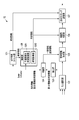
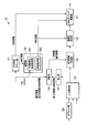
- FIG. 1 is a block diagram illustrating functional configurations of a transmission system and a reception device according to the present embodiment.
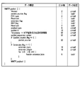
- FIG. 2 is a diagram illustrating a data structure of the MMTP packet according to the present embodiment.
- FIG. 3 is a block diagram showing a functional configuration of the multiplexing apparatus shown in FIG.
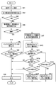
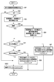
- FIG. 4 is a flowchart showing an operation when the multiplexing apparatus shown in FIG. 3 transmits an MMTP packet in consideration of leap second correction.
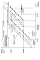
- FIG. 5 is a diagram for explaining the operation of the multiplexing apparatus when a leap second insertion occurs.
- FIG. 6 is a diagram for explaining the operation of the multiplexing apparatus when leap second deletion occurs.
- FIG. 7 is a block diagram showing another example of the functional configuration of the multiplexing apparatus shown in FIG. FIG.
- FIG. 8 is a block diagram showing a functional configuration of the receiving apparatus shown in FIG.
- FIG. 9 is a flowchart showing an operation when the receiving apparatus shown in FIG. 8 buffers an MMTP packet in consideration of leap second correction.
- FIG. 10 is a block diagram illustrating another example of the functional configuration of the receiving apparatus illustrated in FIG.
- FIG. 11 is a block diagram illustrating another example of the functional configuration of the receiving apparatus illustrated in FIG.
- FIG. 1 is a block diagram illustrating an example of functional configurations of the transmission system 10 and the reception device 20 according to the present embodiment.
- the transmission system 10 illustrated in FIG. 1 transmits a multiplexed packet in which MMTP (MPEG Media Transport Protocol) packets are multiplexed.
- MMTP MPEG Media Transport Protocol
- the transmitted multiplexed packet reaches the reception device 20 via a transmission path such as a broadcast network and is received by the reception device 20.
- MMTP MPEG Media Transport Protocol
- the transmission system 10 includes a material output device 11, a multiplexing device 12, and a transmission device 13.
- the material output device 11 includes, for example, a CPU (Central Processing Unit), an FPGA (Field Programmable Gate Array) that executes predetermined processing in accordance with control from the CPU, and a storage memory for storing data.
- the material output device 11 implements functions such as a video encoder and an audio encoder, for example, by the CPU executing functions designed for the FPGA.
- the video encoder for example, encodes video data stored in a storage memory and uses it as a video MMTP packet.
- the audio encoder for example, encodes audio data stored in the storage memory and generates an audio MMTP packet.
- the material output device 11 outputs a plurality of types of MMTP packets for video and audio to the multiplexing device 12.
- the material output device 11 may include an LSI (Large-Scale Integration) instead of the FPGA. Further, the material output device 11 may execute predetermined processing by software processing by the CPU.
- LSI Large-Scale Integration
- FIG. 2 is a diagram showing an example of the data structure of the MMTP packet according to the present embodiment.
- the header of the MMTP packet is given a 32-bit short format NTP (Network Time Protocol) time stamp.
- the short format NTP time stamp includes 16 bits of integer second time information and 16 bits of fractional second time information.
- the short format NTP time stamp describes, for example, the time when the MMTP packet is output from the preceding device, that is, the material output device 11.
- the multiplexing device 12 includes, for example, a CPU and an FPGA that executes predetermined processing in accordance with control from the CPU.
- FIG. 3 is a block diagram illustrating an example of a functional configuration of the multiplexing device 12 illustrated in FIG.
- the control part 128 shown by FIG. 3 is comprised by CPU.
- the multiplexing device 12 may include an LSI instead of the FPGA to realize the function shown in FIG. Further, the multiplexing device 12 may realize the function shown in FIG. 3 by software processing by the CPU.
- the NTP time count unit 121 includes an RTC (Real Time Clock) and generates time information in the multiplexing device 12.
- the NTP time count unit 121 outputs the generated time information to the transmission timing adjustment unit 127 and the control unit 128.
- the NTP time counting unit 121 receives an NTP packet transmitted from an NTP server (not shown), and adjusts time information generated based on the received NTP packet.
- the NTP packet is provided with a 64-bit long format NTP timestamp including 32 seconds of integer second time information and 32 bits of fractional second time information.
- the NTP packet includes leap second information (LeapLeIndicator) indicating insertion or deletion of leap seconds.
- the input selection unit 122 receives a plurality of MMTP packets output from the material output device 11.
- the input selection unit 122 may receive MMTP packets output from devices other than the material output device 11 in parallel.
- the input selection unit 122 includes, for example, a ring buffer (not shown), and temporarily holds a plurality of received MMTP packets in the ring buffer.
- the control unit 128 creates management information when the MMTP packet is held in the ring buffer.
- the management information is information for managing the MMTP packet stored in the buffer.
- the management information includes, for example, the time stamp of the MMTP packet stored in the buffer, the start address of the stored MMTP packet, the size of the stored MMTP packet, and the like.
- the input selection unit 122 selects MMTP packets from the plurality of received MMTP packets in ascending order of time stamp values, and outputs the selected MMTP packets to the extraction unit 123 and the management information creation unit 125.
- the input selection unit 122 selects these MMTP packets one by one in an order according to a predetermined rule. If there is an MMTP packet for which some priority is set, the MMTP packet to which the priority is assigned may be preferentially selected.
- the extraction unit 123 extracts 16-bit integer second time information from the short-format NTP timestamp added to the MMTP packet output from the input selection unit 122.
- the extraction unit 123 outputs the extracted integer second time information to the determination unit 124 as first integer second time information.
- the control unit 128 is realized by, for example, CPU processing and controls the operation of the multiplexing device 12.
- the control unit 128 implements the functions of the discontinuity occurrence time acquisition unit 1281 and the time acquisition unit 1282 by the CPU executing a predetermined program.
- the discontinuity occurrence time acquisition unit 1281 receives 32-bit integer time information output from the NTP time count unit 121 and leap second information included in the NTP packet.
- the leap second is inserted in UTC (Coordinated ⁇ ⁇ Universal Time) after 23:59:59 on December 31 or June 30 of a predetermined year.
- the MTP server 23:59:59 on December 31 or June 30 of a predetermined year is deleted as a leap second in UTC.
- the leap second information is transmitted from the NTP server, for example, several months before the time when the leap second is inserted or deleted.
- the discontinuity occurrence time acquisition unit 1281 determines the discontinuity occurrence time as follows.
- the discontinuity occurrence time is a time related to discontinuity that occurs by correcting leap seconds.
- the discontinuity occurrence time acquisition unit 1281 receives the leap second information based on the leap second information for inserting the leap second and the integer second time information 32 bits output from the NTP time count unit 121. It is determined that the most recent time on December 31 or June 30 at 23:59:59 is the discontinuity occurrence time. Further, the discontinuity occurrence time acquisition unit 1281 is based on the leap second information indicating that the leap second is to be deleted and the integer second time information 32 bits output from the NTP time counting unit 121, and immediately after receiving the leap second information. It is determined that 23:59:58 on December 31 or June 30 is the discontinuity occurrence time.
- the discontinuity occurrence time acquisition unit 1281 When the discontinuity occurrence time acquisition unit 1281 acquires the discontinuity occurrence time, it outputs identification information of processing (insertion or deletion) for leap seconds and lower 16 bits of integer second time information related to the discontinuity occurrence time to the determination unit 124. To do.
- the lower 16 bits of the integer second time information regarding the discontinuity occurrence time are referred to as second integer second time information.
- the discontinuity occurrence time acquisition unit 1281 outputs the identification information and the second integer second time information to the determination unit 124, for example, several minutes before the discontinuity occurrence time.
- the time acquisition unit 1282 acquires time information in a format corresponding to the short format NTP timestamp from the NTP time count unit 121. This time information indicates, for example, the lower 16 bits of integer time information and the upper 16 bits of decimal time information in the long format NTP timestamp.
- the time acquisition unit 1282 outputs the acquired time information to the continuity determination unit 126 and the transmission timing adjustment unit 127.
- the determination unit 124 receives the identification information of the process for leap seconds and the second integer second time information output from the discontinuity occurrence time acquisition unit 1281, and receives the received identification information and second integer second time information. And record.
- the determination unit 124 receives the first integer second time information sequentially output from the extraction unit 123.
- the determination unit 124 determines whether or not the received first integer second time information matches the recorded second integer second time information. If they match, the determination unit 124 outputs to the management information creation unit 125 matching information indicating that they match and identification information for processing for leap seconds.
- the management information creation unit 125 adds the matching information and identification information output from the determination unit 124 to the management information regarding the MMTP packet output from the input selection unit 122.
- the continuity determination unit 126 determines the continuity of the MMTP packet as follows, and deletes the matching information and the identification information from the management information of the MMTP packet after the continuity is interrupted. That is, the continuity determination unit 126 calculates the difference between the short format NTP timestamp attached to the MMTP packet and the time information acquired by the time acquisition unit 1282 of the control unit 128.
- the MMTP packet output from the material output device 11 which is the preceding device arrives at the multiplexing device 12 later than the ideal situation due to factors such as a switch. Therefore, if there is no leap second insertion and deletion, the value of the short-format NTP timestamp attached to the MMTP packet is smaller than the value of the time information acquired by the time acquisition unit 1282.
- the continuity determination unit 126 reads management information and confirms the contents of the management information.
- the management information includes identification information indicating that matching information and leap seconds are to be inserted
- the continuity determination unit 126 detects a change in the sign of the calculated difference.
- the continuity determination unit 126 when the calculated sign of the difference changes as positive, negative, positive, the short format NTP timestamp attached to the MMTP packet when the difference sign changes from negative to positive. Judged to be discontinuous. If it is determined that the short-format NTP timestamp attached to the MMTP packet has become discontinuous, the continuity determination unit 126 deletes the matching information and the identification information from the management information of the MMTP packet after determining that it is discontinuous.
- the continuity determination unit 126 detects a change in the calculated difference.
- the calculated difference changes like a value less than 1 second, a value exceeding 1 second, a value exceeding 1 second, or a value less than 1 second
- the difference is changed from a value exceeding 1 second to a value less than 1 second. It is determined that the short-format NTP timestamp attached to the MMTP packet when it has changed becomes discontinuous. If it is determined that the short-format NTP timestamp attached to the MMTP packet has become discontinuous, the continuity determination unit 126 deletes the matching information and the identification information from the management information of the MMTP packet after determining that it is discontinuous.
- the transmission timing adjustment unit 127 reads the MMTP packet from the buffer.
- the transmission timing adjustment unit 127 determines whether or not it is necessary to rewrite the short format NTP timestamp added to the MMTP packet. For example, when the short format NTP time stamps attached to two MMTP packets simultaneously input to the input selection unit 122 indicate the same time, output after multiplexing cannot be performed simultaneously. That is, after one MMTP packet is output, the other MMTP packet is output. Therefore, the transmission timing adjustment unit 127 rewrites the short format NTP time stamp added to the latter MMTP packet.
- the transmission timing adjustment unit 127 refers to the time information of the short time NTP time stamp of the integer second time information 32 bits output from the NTP time count unit 121 and the fractional second time information 32 bits, and the MMTP packet Is rewritten based on the transmission rate at the time of transmitting to the transmission device 13 and the packet size of the MMTP packet transmitted immediately before.
- the transmission timing adjustment unit 127 transmits the MMTP packet read from the buffer to the transmission device 13 as a multiplexed packet according to the added short format NTP timestamp.
- the transmission timing adjustment unit 127 when the transmission timing adjustment unit 127 reads out the MMTP packet from the buffer, the transmission timing adjustment unit 127 reads out the matching information and the identification information included in the management information.
- the transmission timing adjustment unit 127 calculates a difference between the short format NTP timestamp attached to the MMTP packet and the time information acquired by the time acquisition unit 1282 of the control unit 128.
- the transmission timing adjustment unit 127 sets the rewritten short format NTP timestamp to 00. It is determined whether or not hour 00 minute 00 second is exceeded. In the present embodiment, 00:00:00 means the time when the date changes.
- the transmission timing adjustment unit 127 decreases the value of the short format NTP timestamp after rewriting by 1 second.
- the transmission timing adjustment unit 127 reads the rewritten short format NTP timestamp. It is judged whether or not it exceeds 23:59:59. When the rewritten short format NTP timestamp exceeds 23:59:59, the transmission timing adjustment unit 127 increases the value of the short format NTP timestamp after rewriting by 1 second.
- the transmission device 13 performs transmission processing on the MMTP packet output from the multiplexing device 12.
- the transmission device 13 transmits the MMTP packet subjected to the transmission process.
- FIG. 4 is a flowchart showing an operation when the multiplexing apparatus 12 transmits an MMTP packet in consideration of leap second correction.
- the discontinuity occurrence time acquisition unit 1281 of the control unit 128 receives identification information of processing (insertion or deletion) for leap seconds, and lower 16 bits of integer second time information related to the discontinuity occurrence time (second integer second time) Information) is output to the determination unit 124 in advance.
- FIG. 5 is a diagram for explaining an example of the operation of the multiplexer 12 when a leap second insertion occurs.
- FIG. 6 is a diagram for explaining an example of the operation of the multiplexing device 12 when leap second deletion occurs.
- the horizontal axis represents the time for the system clock (UTC) counted by the NTP time counting unit 121
- the vertical axis represents the time for the time stamp of the MMTP packet.
- the solid line represents the system clock counted by the NTP time counting unit 121
- the broken line represents the time indicated by the time stamp of the MMTP packet received by the input selection unit 122
- the alternate long and short dash line is It represents the time indicated by the time stamp of the MMTP packet sent by the sending timing adjustment unit 127.
- the input selection unit 122 receives a plurality of MMTP packets. 5 and 6, the MMTP packets P (n ⁇ 2), P (n ⁇ 1), and P (n) received by the input selection unit 122 are transmitted because the assigned time stamps are close. It is necessary to adjust the timing.
- the input selection unit 122 selects MMTP packets from the plurality of received MMTP packets in ascending order of time stamp values (step S41).
- the extraction unit 123 extracts 16-bit integer second time information as first integer second time information from the short-format NTP timestamp assigned to the MMTP packet selected by the input selection unit 122 (step S42).
- the determination unit 124 determines whether or not the first integer second time information extracted by the extraction unit 123 matches the recorded second integer second time information (step S43). If they match (Yes in step S43), the determination unit 124 notifies the management information creation unit 125 of the matching information indicating the matching and the processing identification information for the leap second. The management information creation unit 125 adds the matching information and identification information output from the determination unit 124 to the management information about the MMTP packet (step S44).
- the continuity determination unit 126 determines the continuity of the MMTP packet while referring to the management information (step S45).
- the transmission timing adjustment unit 127 reads the MMTP packets from the buffer (step S46).
- the continuity determination unit 126 deletes the matching information and the identification information from the management information of the MMTP packets after the continuity is interrupted (step S47), and the process is performed.
- the process proceeds to S46.
- the matching information and the identification information are deleted from the management information after the MMTP packet P (n) in FIGS. 5 and 6, the management information for the shaded packet includes matching information and identification information.
- the transmission timing adjustment unit 127 determines whether or not it is necessary to rewrite the short format NTP timestamp added to the MMTP packet (step S48). When it is not necessary to rewrite (No in step S48), the transmission timing adjustment unit 127 outputs the MMTP packet to the transmission device 13 as a multiplexed packet according to the added short format NTP timestamp (step S49), and processing End. When it is necessary to rewrite (Yes in step S48), the transmission timing adjustment unit 127 rewrites the short format NTP timestamp (step S410).
- the transmission timing adjustment unit 127 determines whether or not the MMTP packet in which the short format NTP timestamp is rewritten satisfies the first condition (step S411).
- the first condition is that the coincidence information is read, the identification information for inserting the leap second is read, and the sign of the calculated difference is negative.
- the transmission timing adjustment unit 127 determines whether or not the rewritten time stamp exceeds 00:00:00 (step S412).
- the transmission timing adjustment unit 127 further rewrites the rewritten time stamp value by 1 second (step S413), and the process proceeds to step S49. To move to.
- the transmission timing adjustment unit 127 shifts the process to step S49.
- MMTP packets P (n ⁇ 2), P (n ⁇ 1), and P (n) have close time stamps, so that the transmission timing needs to be adjusted.
- the transmission timing adjustment unit 127 rewrites the time stamp so that the MMTP packet P (n ⁇ 1) is transmitted at the timing of the MMTP packet P ′ (n ⁇ 1) indicated on the one-dot chain line. Further, the transmission timing adjustment unit 127 rewrites the time stamp so that the MMTP packet P (n) is transmitted at the timing of the MMTP packet P ′ (n) indicated on the alternate long and short dash line.
- the transmission timing adjustment unit 127 determines whether or not the rewritten time stamp exceeds 00:00:00 because the MMTP packets P ′ (n ⁇ 1) and P ′ (n) satisfy the first condition. . Since the time stamp of the MMTP packet P ′ (n) exceeds 00:00:00, the transmission timing adjustment unit 127 further rewrites the time stamp value of the MMTP packet P ′ (n) by 1 second.
- Step S411 when the MMTP packet does not satisfy the first condition (No in Step S411), the transmission timing adjustment unit 127 determines whether or not the MMTP packet satisfies the second condition (Step S414).
- the second condition is that the coincidence information is read, the identification information for deleting the leap second is read, and the calculated difference exceeds 1 second.
- the transmission timing adjustment unit 127 determines whether or not the rewritten time stamp exceeds 23:59:59 (step S415).
- step S415 When the rewritten time stamp exceeds 23:59:59 (Yes in step S415), the transmission timing adjustment unit 127 further rewrites the rewritten time stamp value by 1 second (step S416), and the process proceeds to step S49. To move to. If the rewritten time stamp does not exceed 23:59:59 (No in step S415), the transmission timing adjustment unit 127 shifts the process to step S49.
- MMTP packets P (n ⁇ 2), P (n ⁇ 1), and P (n) are close in assigned time stamps, so it is necessary to adjust the transmission timing.
- the transmission timing adjustment unit 127 rewrites the time stamp so that the MMTP packet P (n ⁇ 1) is transmitted at the timing of the MMTP packet P ′ (n ⁇ 1) indicated on the one-dot chain line. Further, the transmission timing adjustment unit 127 rewrites the time stamp so that the MMTP packet P (n) is transmitted at the timing of the MMTP packet P ′ (n) indicated on the alternate long and short dash line.
- the transmission timing adjustment unit 127 determines whether or not the rewritten time stamp exceeds 23:59:59 because the MMTP packets P ′ (n ⁇ 1) and P ′ (n) satisfy the second condition. . Since the time stamp of the MMTP packet P ′ (n) exceeds 23:59:59, the transmission timing adjustment unit 127 further rewrites the time stamp value of the MMTP packet P ′ (n) by one second.
- step S43 if the first integer second time information extracted by the extraction unit 123 does not match the recorded second integer second time information (No in step S43), the process proceeds to step S46.
- the determination unit 124 uses the second integer time information output from the extraction unit 123 as the second integer time information output from the discontinuity occurrence time acquisition unit 1281. It is determined whether or not it matches the integer second time information.
- the management information creation unit 125 adds the coincidence information indicating the coincidence and the processing identification information for the leap second to the management information.
- the continuity determining unit 126 determines the difference between the matching information and the identification information included in the management information, the short format NTP time stamp attached to the MMTP packet, and the time information acquired by the time acquiring unit 1282 of the control unit 128.
- a plurality of MMTP packets near the MMTP packet in which the time stamps are discontinuous are specified. Then, when the time stamps of the plurality of identified MMTP packets are rewritten at a time that does not consider the leap second correction, the transmission timing adjustment unit 127 takes into account the leap second correction after the rewriting time. I am trying to rewrite it further. As a result, the order of MMTP packets is maintained correctly.
- MMTP packets can be transmitted in the correct order even when leap second insertion or deletion occurs. For this reason, when the video and audio clocks are reproduced by a PLL or the like using NTP in the transmission device and the reception device, clock synchronization during the leap second correction period is correctly performed. As a result, NTSC subcarriers can be accurately reproduced and audio wow and flutter can be suppressed.
- the multiplexing apparatus 12 may include an offset unit 129 before the input selection unit 122, as shown in FIG.
- the delay time of a predetermined MMTP packet may be larger than the delay times of other MMTP packets.
- the offset unit 129 is set with an offset value that can reduce the difference in delay time between MMTP packets.
- the discontinuity occurrence time acquisition unit 1281 acquires the discontinuity occurrence time, the identification information of the processing (insertion or deletion) for the leap second and the integer second time information lower 16 regarding the discontinuity occurrence time.
- the case where the bits are output to the determination unit 124 has been described as an example. However, it is not limited to this.
- the discontinuity occurrence time acquisition unit 1281 determines the lower 16 bits of the integer second time information out of the 32 bits of the integer second time information output from the NTP time counting unit 121 when the leap second information does not instruct the processing for the leap second.
- the data may be output to the unit 124.
- the discontinuity occurrence time acquisition unit 1281 outputs identification information indicating that there is no processing for leap seconds to the determination unit 124.
- FIG. 8 is a block diagram illustrating an example of a functional configuration of the receiving device 20 illustrated in FIG.
- the receiving device 20 includes, for example, a CPU, an FPGA that executes predetermined processing according to control from the CPU, and a storage memory for storing data.
- the control unit 28 shown in FIG. 8 is configured by a CPU.
- the receiving device 20 may include an LSI instead of the FPGA to realize the function shown in FIG. Further, the receiving device 20 may realize the function shown in FIG. 8 by software processing by the CPU.
- the NTP time counting unit 21 includes an RTC and generates time information in the receiving device 20.
- the NTP time count unit 21 outputs the generated time information to the reception buffer input unit 26 and the control unit 28.
- the NTP time counting unit 21 receives an NTP packet transmitted from an NTP server (not shown), and adjusts time information generated based on the received NTP packet.
- the NTP packet is provided with a 64-bit long format NTP timestamp including 32 seconds of integer second time information and 32 bits of fractional second time information.
- the NTP packet includes leap second information (LeapdicIndicator) instructing insertion or deletion of leap seconds.
- the extraction unit 22 extracts 16-bit integer second time information from the short-format NTP time stamp added to the MMTP packet received by the receiving device 20.
- the extraction unit 22 outputs the extracted integer second time information to the determination unit 23 as first integer second time information.
- the control unit 28 is realized by, for example, CPU processing, and controls the operation of the receiving device 20. Further, the control unit 28 realizes the functions of the discontinuity occurrence time acquisition unit 281 and the time acquisition unit 282 by the CPU executing a predetermined program.
- the discontinuity occurrence time acquisition unit 281 receives the 32-bit integer time information output from the NTP time count unit 21 and the leap second information included in the NTP packet.
- the discontinuity occurrence time acquisition unit 281 determines the discontinuity occurrence time as follows.
- the discontinuity occurrence time acquisition unit 281 receives leap second information based on leap second information for inserting a leap second and integer second time information 32 bits output from the NTP time count unit 21. It is determined that the most recent time on December 31 or June 30 at 23:59:59 is the discontinuity occurrence time. Also, the discontinuity occurrence time acquisition unit 281 is based on the leap second information indicating that the leap second is deleted and the integer second time information 32 bits output from the NTP time counting unit 21, and immediately after receiving the leap second information. It is determined that 23:59:58 on December 31 or June 30 is the discontinuity occurrence time.
- the discontinuity occurrence time acquisition unit 281 When the discontinuity occurrence time acquisition unit 281 acquires the discontinuity occurrence time, it outputs identification information of processing (insertion or deletion) for leap seconds and lower 16 bits of integer second time information related to the discontinuity occurrence time to the determination unit 23. To do.
- the lower 16 bits of the integer second time information regarding the discontinuity occurrence time are referred to as second integer second time information.
- the discontinuity occurrence time acquisition unit 281 outputs the identification information and the second integer second time information to the determination unit 23, for example, several minutes before the discontinuity occurrence time.
- the time acquisition unit 282 acquires time information in a format corresponding to the short format NTP timestamp from the NTP time count unit 21. This time information indicates, for example, the lower 16 bits of integer time information and the upper 16 bits of decimal time information in the long format NTP timestamp.
- the time acquisition unit 282 outputs the acquired time information to the continuity determination unit 25 and the reception buffer input unit 26.
- the determination unit 23 receives the identification information of the process for leap seconds and the second integer second time information output from the discontinuity occurrence time acquisition unit 281 and receives the received identification information and second integer second time information. And record.
- the determination unit 23 receives first integer second time information sequentially output from the extraction unit 22.
- the determination unit 23 determines whether or not the received first integer second time information matches the recorded second integer second time information. If they match, the determination unit 23 outputs matching information indicating that they match and identification information for processing for leap seconds to the management information creation unit 24.
- the management information creation unit 24 adds the matching information and identification information output from the determination unit 23 to the management information about the MMTP packet received by the receiving device 20.
- the reception buffer input unit 26 described later includes, for example, a ring buffer, and temporarily stores the received MMTP packet in the ring buffer.
- the management information is information for managing the MMTP packet stored in the buffer.
- the management information includes, for example, the time stamp of the MMTP packet stored in the buffer, the start address of the stored MMTP packet, the size of the stored MMTP packet, and the like.
- the continuity determination unit 25 determines the continuity of the MMTP packet as described below, and deletes the matching information and the identification information from the management information of the MMTP packet after the continuity is interrupted. That is, the continuity determination unit 25 calculates the difference between the short format NTP timestamp attached to the MMTP packet and the time information acquired by the time acquisition unit 282 of the control unit 28. The continuity determination unit 25 reads management information and confirms the contents of the management information. When the management information includes identification information indicating that matching information and leap seconds are to be inserted, the continuity determination unit 25 detects a change in the sign of the calculated difference. When the calculated difference sign changes from positive to negative to positive, the continuity determination unit 25 uses the short NTP time stamp attached to the MMTP packet when the difference sign changes from negative to positive.
- the continuity determination unit 25 deletes the match information and the identification information from the management information of the MMTP packet that has been determined to be discontinuous. In addition, the continuity determination unit 25 detects the discontinuity of the short-form NTP timestamp attached to the MMTP packet due to the process of inserting the leap second of this packet into the management information of the MMTP packet determined to be discontinuous. A first index indicating that the packet has occurred is added.
- the continuity determination unit 25 detects a change in the calculated difference.
- the calculated difference changes like a value less than 1 second, a value exceeding 1 second, or a value less than 1 second, the difference is changed from a value exceeding 1 second to a value less than 1 second. It is determined that the short-format NTP timestamp attached to the MMTP packet when it has changed becomes discontinuous. If it is determined that the short-format NTP time stamp attached to the MMTP packet has become discontinuous, the continuity determination unit 25 deletes the match information and the identification information from the management information of the MMTP packet that has been determined to be discontinuous.
- the continuity determination unit 25 indicates that the discontinuity of the short format NTP time stamp attached to the MMTP packet accompanying the process of deleting the leap second of this packet is included in the management information of the MMTP packet determined to be discontinuous. A second index indicating that the packet has occurred is added.
- the reception buffer input unit 26 holds the received MMTP packet in the ring buffer.
- the ring buffer may be a FIFO (First In First Out).
- the reception buffer input unit 26 adjusts the order in which the MMTP packets are held in the ring buffer as follows. That is, the reception buffer input unit 26 calculates the difference between the short format NTP timestamp attached to the MMTP packet and the time information acquired by the time acquisition unit 282 of the control unit 28.
- the reception buffer input unit 26 reads the matching information and identification information included in the management information.
- the MMTP packet is held in the buffer so that the MMTP packet to which the management information including the index is added is located.
- the reception buffer input unit 26 outputs the second difference after the MMTP packet to which the calculated difference exceeds 1 second and the management information including the identification information for deleting the coincidence information and the leap second is added.
- the MMTP packet is held in the buffer so that the MMTP packet to which the management information including the index is added is located.
- the reception buffer input unit 26 outputs the held MMTP packet to the reception unit 27 according to predetermined timing or predetermined control.
- FIG. 9 is a flowchart illustrating an operation when the receiving apparatus 20 buffers MMTP packets in consideration of leap second correction.
- the discontinuity occurrence time acquisition unit 281 of the control unit 28 receives identification information of processing (insertion or deletion) for leap seconds, and lower 16 bits of integer second time information related to the discontinuity occurrence time (second integer second time) Information) is output to the determination unit 23 in advance.
- the extraction unit 22 extracts 16-bit integer second time information from the short-format NTP timestamp added to the MMTP packet received by the receiving device 20 (step S91).
- the determining unit 23 determines whether or not the first integer second time information extracted by the extracting unit 22 matches the recorded second integer second time information (step S92). If they match (Yes in step S92), the determination unit 23 notifies the management information creation unit 24 of the match information indicating the match and the process identification information for the leap second.
- the management information creation unit 24 adds the matching information and identification information output from the determination unit 23 to the management information for the MMTP packet (step S93).
- the continuity determination unit 25 determines the continuity of the MMTP packet while referring to the management information (step S94).
- the reception buffer input unit 26 determines whether or not the first index is added to the management information of the MMTP packet (Step S95).
- the short NTP time stamp attached to the MMTP packet is discontinuous (No in step S94)
- the matching information and the identification information are deleted from the management information of the MMTP packet, and the first or second index is added to the management information. Is added (step S96).
- step S95 when the first index is added to the management information of the MMTP packet (Yes in step S95), the reception buffer input unit 26 has a negative sign of the calculated difference, and matches information and leap.
- the MMTP packet is stored in the buffer so that the MMTP packet with the management information including the first index is located next to the MMTP packet with the management information including the identification information for inserting the second. Hold (step S97).
- the reception buffer input unit 26 determines whether or not the second index is added to the management information of the MMTP packet. (Step S98).
- the reception buffer input unit 26 deletes the coincidence information and the leap second when the calculated difference exceeds 1 second.
- the MMTP packet is held in the buffer so that the MMTP packet to which the management information to which the second index is added is located next to the MMTP packet to which the management information including the identification information is assigned (step S99). ).
- step S98 when the second index is not added to the management information of the MMTP packet (No in step S98), the reception buffer input unit 26 holds the MMTP packet in the buffer (step S910).
- the determination unit 23 uses the second integer time information output from the extraction unit 22 as the second integer time information output from the discontinuity occurrence time acquisition unit 281. It is determined whether or not it matches the integer second time information.
- the management information creation unit 24 adds the coincidence information indicating the coincidence and the processing identification information for the leap second to the management information.
- the continuity determination unit 25 determines the difference between the coincidence information and the identification information included in the management information, the short-format NTP timestamp attached to the MMTP packet, and the time information acquired by the time acquisition unit 282 of the control unit 28. Based on the above, the MMTP packet before and after the discontinuity occurrence time is specified.
- the reception buffer input unit 26 holds the MMTP packet immediately after the discontinuity occurrence time in the buffer so that it is positioned next to the MMTP packet immediately before the discontinuity occurrence time. As a result, the order of MMTP packets is maintained correctly.
- the receiving device 20 can receive MMTP packets in the correct order even when leap second insertion or deletion occurs.
- the discontinuity occurrence time acquisition unit 281 acquires the discontinuity occurrence time, the identification information of the process (insertion or deletion) for leap seconds and the integer second time information lower 16 regarding the discontinuity occurrence time.
- the case where the bits are output to the determination unit 23 has been described as an example. However, it is not limited to this.
- the discontinuity occurrence time acquisition unit 281 determines the lower 16 bits of the integer second time information out of the 32 bits of the integer second time information output from the NTP time counting unit 21 when the leap second information does not instruct processing regarding the leap second. You may output to the part 23. At this time, the discontinuity occurrence time acquisition unit 281 outputs identification information indicating that there is no processing for leap seconds to the determination unit 23.
- the receiving apparatus 20 may include an offset / jitter calculating unit 29 as shown in FIG.
- the offset / jitter calculation unit 29 receives the first integer second time information output from the extraction unit 22 and the lower 16 bits of integer second time information output from the discontinuity occurrence time acquisition unit 281 via the determination unit 23. Receive.
- the offset / jitter calculation unit 29 monitors the difference between the first integer second time information and the lower 16 bits of the integer second time information, and stores the maximum value of the transmission line delay in advance.
- the offset / jitter calculation unit 29 outputs the maximum value of the transmission line delay to the determination unit 23 as an offset.
- the determination unit 23 subtracts the offset value from the second integer second time information output from the discontinuity occurrence time acquisition unit 281 and compares the subtracted time with the first integer second time information.
- the receiving device 20 may include an extraction / packet alignment unit 210 instead of the extraction unit 22 as shown in FIG.
- Extraction / packet alignment section 210 uses at least one of packet_counter and packet_sequence_number as auxiliary information, and arranges the order of received MMTP packets. Thereby, even when the network jitter is large on the receiving side, the order of the MMTP packets can be maintained correctly.
Landscapes
- Engineering & Computer Science (AREA)
- Signal Processing (AREA)
- Multimedia (AREA)
- Computer Networks & Wireless Communication (AREA)
- Computer Security & Cryptography (AREA)
- Computer Hardware Design (AREA)
- Two-Way Televisions, Distribution Of Moving Picture Or The Like (AREA)
- Synchronisation In Digital Transmission Systems (AREA)
- Electric Clocks (AREA)
Abstract
送信システムは、出力装置と、多重化装置とを具備する。多重化装置は、抽出部、不連続発生時刻取得部、判断部、管理情報作成部、連続性判定部及び送出タイミング調整部を備える。判断部は、抽出部により抽出された第1の整数秒時刻情報が、不連続発生時刻取得部により取得された第2の整数秒時刻情報と一致するか否かを判断する。管理情報作成部は、一致する場合、一致情報と識別情報とを作成する。連続性判定部は、一致情報及び識別情報等に基づき、短形式NTPタイムスタンプが不連続となるMMTPパケット近傍のMMTPパケットであるか否かを判定する。送出タイミング調整部は、MMTPパケットのタイミング調整時にうるう秒に対する処理を考慮した時刻情報を短形式NTPタイムスタンプに書き込む。
Description
本発明の実施形態は、MMT(MPEG Multimedia Transport)を利用してデータを送信する送信システム、この送信システムで用いられる多重化装置、及び、この多重化装置で用いられるうるう秒補正対応方法に関する。
現在の放送システムでは、MPEG-2 TS(Moving Picture Experts Group-2 Transport Stream)方式、及び、RTP(Real-time Transport Stream)方式のメディアトランスポート方式が広く用いられている。これらの方式では、放送と通信とを協調させようとすると、様々な限界がある。そこで、MPEGを利用して多様なネットワークを用いることを想定した新たなメディアトランスポート方式であるMMT(MPEG Media Transport)が提案されている。
MMT規格(ISO/IEC 23008-1)では、MMTP(MPEG Media Transport Protocol)パケットのヘッダに32ビットの短形式NTP(Network Time Protocol)タイムスタンプが付与されている。短形式NTPタイムスタンプには、整数秒時刻情報16ビットと、小数秒時刻情報16ビットとが含まれる。また、MMT規格では、MMTPパケットにうるう秒情報に相当する指標が含まれていない。なお、うるう秒情報とは、NTP(Network Time Protocol)パケットに含まれる、うるう秒の挿入又は削除を指示する情報(Leap Indicator)である。
MMTPパケットヘッダにはNTP短形式タイムスタンプが付与され、かつ、MMTPパケットにはうるう秒情報に相当する指標が含まれないため、MMT規格を採用する装置は、うるう秒の挿入又は削除により生じる不連続発生時刻を把握することはできない。このため、うるう秒時刻近傍においてMMTPパケットを送信する場合、MMT規格を採用する送信装置は、MMTPパケットを正しい順序で送信できない場合がある。また、うるう秒時刻近傍においてMMTPパケットを受信する場合、MMT規格を採用する受信装置は、MMTPパケットを正しい順序で受信できない場合がある。送信装置及び受信装置において、ビデオ及びオーディオのクロックを、NTPを用いたPLL(Phase Lock Loop)等で再現する場合、うるう秒補正期間中のクロック同期が正しく行われず、NTSC(National Television System Committee)のサブキャリアが正確に再現できなかったり、オーディオのワウフラッターが大きくなり音質低下したりする。
SLEWモード:うるう秒挿入のタイミングで逆進が発生しないように時刻差をゆっくり合わせる、[online]、インターネットURL:http://labunix.hateblo.jp/entry/2012/03/04/194140>
以上のように、MMT規格を採用する装置は、うるう秒の挿入又は削除が発生する場合、MMTPパケットを正しい順序で送信又は受信できないという問題がある。
そこで、目的は、うるう秒の挿入又は削除が発生する場合であっても、MMTPパケットを正しい順序で送信することが可能な送信システム、この送信システムで用いられる多重化装置、及び、この多重化装置で用いられるうるう秒補正対応方法を提供することにある。
実施形態によれば、送信システムは、短形式NTPタイムスタンプが付加されるMMTPパケットを送信する出力装置と、前記MMTPパケットを多重する多重化装置とを具備する。前記多重化装置は、抽出部、不連続発生時刻取得部、判断部、管理情報作成部、連続性判定部及び送出タイミング調整部を備える。抽出部は、前記MMTPパケットに付加される前記短形式NTPタイムスタンプから第1の整数秒時刻情報を抽出する。不連続発生時刻取得部は、NTPパケットに含まれるうるう秒に関する情報及びNTPに基づいて取得される時刻情報に基づき、前記うるう秒に対する処理と、うるう秒を補正することで発生する不連続発生時刻についての第2の整数秒時刻情報とを取得する。判断部は、前記第1の整数秒時刻情報が、前記第2の整数秒時刻情報と一致するか否かを判断する。管理情報作成部は、一致する場合、一致する旨の一致情報と、前記うるう秒に対する処理の識別情報とを作成する。連続性判定部は、前記一致情報、前記識別情報、及び、前記短形式NTPタイムスタンプと、前記NTPに基づいて取得される時刻情報との差に基づき、前記短形式NTPタイムスタンプが不連続となるMMTPパケット近傍のMMTPパケットであるか否かを判定する。送出タイミング調整部は、前記短形式NTPタイムスタンプが不連続となるMMTPパケット近傍のMMTPパケットを送出するタイミングを調整する場合、うるう秒に対する処理を考慮した時刻情報を、前記MMTPパケットに付加される短形式NTPタイムスタンプに書き込む。
以下、実施の形態について、図面を参照して説明する。
図1は、本実施形態に係る送信システム10と、受信装置20との機能構成の例を示すブロック図である。図1に示す送信システム10は、MMTP(MPEG Media Transport Protocol)パケットを多重した多重化パケットを送信する。送信された多重化パケットは、放送ネットワーク等の伝送路を介して受信装置20へ到達し、受信装置20により受信される。
(送信システム10)
送信システム10は、素材出力装置11、多重化装置12及び送信装置13を具備する。
送信システム10は、素材出力装置11、多重化装置12及び送信装置13を具備する。
素材出力装置11は、例えば、CPU(Central Processing Unit)、CPUからの制御に従って所定の処理を実行するFPGA(Field Programmable Gate Array)、及び、データを蓄積するためのストレージメモリ等を備える。素材出力装置11は、CPUがFPGAに設計される機能を実行することで、例えば、ビデオエンコーダ及びオーディオエンコーダ等の機能を実現する。ビデオエンコーダは、例えば、ストレージメモリに蓄積される映像データを符号化し、映像のMMTPパケットとする。オーディオエンコーダは、例えば、ストレージメモリに蓄積される音声データを符号化し、音声のMMTPパケットとする。素材出力装置11は、映像及び音声等についての複数の種類のMMTPパケットを多重化装置12へ出力する。
なお、素材出力装置11は、FPGAの代わりにLSI(Large-Scale Integration)を備えるようにしても構わない。また、素材出力装置11は、CPUによるソフトウェア処理により所定の処理を実行するようにしても構わない。
図2は、本実施形態に係るMMTPパケットのデータ構造の例を示す図である。MMTPパケットのヘッダには、32ビットの短形式NTP(Network Time Protocol)タイムスタンプが付与されている。短形式NTPタイムスタンプには、整数秒時刻情報16ビットと、小数秒時刻情報16ビットとが含まれる。短形式NTPタイムスタンプには、例えば、前段の装置、すなわち、素材出力装置11からMMTPパケットが出力されたときの時刻が記載される。
多重化装置12は、例えば、CPU、及び、CPUからの制御に従って所定の処理を実行するFPGA等を備える。図3は、図1に示される多重化装置12の機能構成の例を示すブロック図である。図3に示されるNTP時刻カウント部121、入力選択部122、抽出部123、判断部124、管理情報作成部125、連続性判定部126及び送出タイミング調整部127の機能は、CPUがFPGAに設計される機能を実行することで実現される。図3に示される制御部128は、CPUにより構成される。なお、多重化装置12は、FPGAの代わりにLSIを備えることで、図3に示される機能を実現するようにしても構わない。また、多重化装置12は、CPUによるソフトウェア処理により、図3に示される機能を実現しても構わない。
NTP時刻カウント部121は、RTC(Real Time Clock)を備え、多重化装置12における時刻情報を生成する。NTP時刻カウント部121は、生成した時刻情報を、送出タイミング調整部127及び制御部128へ出力する。
また、NTP時刻カウント部121は、NTPサーバ(図示せず)から送信されるNTPパケットを受信し、受信したNTPパケットに基づいて生成する時刻情報を調整する。なお、NTPパケットには、整数秒時刻情報32ビットと、小数秒時刻情報32ビットとを含む64ビットの長形式NTPタイムスタンプが付与されている。また、NTPパケットには、うるう秒の挿入又は削除を示すうるう秒情報(Leap Indicator)が含まれる。
入力選択部122は、素材出力装置11から出力される複数のMMTPパケットを受信する。なお、入力選択部122は、素材出力装置11以外の装置から出力されるMMTPパケットを並列して受信しても構わない。入力選択部122は、例えば、リングバッファ(図示せず)を備え、受信した複数のMMTPパケットをリングバッファに一時的に保持する。制御部128は、MMTPパケットがリングバッファに保持される際、管理情報を作成する。管理情報は、バッファに格納されるMMTPパケットを管理するための情報である。管理情報には、例えば、バッファに格納されるMMTPパケットのタイムスタンプ、格納されるMMTPパケットの先頭アドレス、及び、格納されるMMTPパケットのサイズ等が含まれる。
入力選択部122は、受信した複数のMMTPパケットから、タイムスタンプの値が小さい順にMMTPパケットを選択し、選択したMMTPパケットを抽出部123及び管理情報作成部125へ出力する。なお、同一のタイムスタンプが付与されている複数のMMTPパケットを受信した等の場合、入力選択部122は、所定の規則に則った順序で、これらのMMTPパケットを1つずつ選択する。何らかの優先度が設定されているMMTPパケットがある場合には、優先度が付されたMMTPパケットを優先的に選択するようにしても良い。
抽出部123は、入力選択部122から出力されるMMTPパケットに付与された短形式NTPタイムスタンプから、16ビットの整数秒時刻情報を抽出する。抽出部123は、抽出した整数秒時刻情報を第1の整数秒時刻情報として判断部124へ出力する。
制御部128は、例えば、CPUの処理により実現され、多重化装置12の動作を制御する。また、制御部128は、CPUが所定のプログラムを実行することで、不連続発生時刻取得部1281及び時刻取得部1282の機能を実現する。
不連続発生時刻取得部1281は、NTP時刻カウント部121から出力される32ビットの整数時刻情報と、NTPパケットに含まれるうるう秒情報とを受信する。なお、NTPサーバにおいて、うるう秒はUTC(Coordinated Universal Time)で所定の年の12月31日又は6月30日の23時59分59秒の後に挿入される。また、MTPサーバにおいて、UTCで所定の年の12月31日又は6月30日の23時59分59秒がうるう秒として削除される。ちなみに、うるう秒情報は、うるう秒の挿入又は削除が行われる時刻の、例えば数ヶ月前からNTPサーバから送信される。
不連続発生時刻取得部1281は、以下のように、不連続発生時刻を決定する。なお、本実施形態において不連続発生時刻とは、うるう秒を補正することで発生する不連続に係る時刻のことである。
具体的には、不連続発生時刻取得部1281は、うるう秒を挿入する旨のうるう秒情報と、NTP時刻カウント部121から出力される整数秒時刻情報32ビットとに基づき、うるう秒情報の受信後から直近の12月31日又は6月30日の23時59分59秒が不連続発生時刻であると判断する。また、不連続発生時刻取得部1281は、うるう秒を削除する旨のうるう秒情報と、NTP時刻カウント部121から出力される整数秒時刻情報32ビットとに基づき、うるう秒情報の受信後から直近の12月31日又は6月30日の23時59分58秒が不連続発生時刻であると判断する。
不連続発生時刻取得部1281は、不連続発生時刻を取得すると、うるう秒に対する処理(挿入又は削除)の識別情報、及び、不連続発生時刻に関する整数秒時刻情報下位16ビットを判断部124へ出力する。以下では、不連続発生時刻に関する整数秒時刻情報下位16ビットを第2の整数秒時刻情報と称する。不連続発生時刻取得部1281は、識別情報及び第2の整数秒時刻情報を、例えば、不連続発生時刻の数分前に判断部124へ出力する。
時刻取得部1282は、NTP時刻カウント部121から、短形式NTPタイムスタンプに対応する形式の時刻情報を取得する。なお、この時刻情報は、例えば、長形式NTPタイムスタンプにおける整数時刻情報下位16ビットと、小数時刻情報上位16ビットとを指す。時刻取得部1282は、取得した時刻情報を連続性判定部126及び送出タイミング調整部127へ出力する。
判断部124は、不連続発生時刻取得部1281から出力される、うるう秒に対する処理の識別情報と、第2の整数秒時刻情報とを受信し、受信した識別情報及び第2の整数秒時刻情報とを記録する。判断部124は、抽出部123から順次出力される第1の整数秒時刻情報を受信する。判断部124は、受信した第1の整数秒時刻情報が、記録している第2の整数秒時刻情報と一致するか否かを判断する。判断部124は、一致する場合、一致する旨の一致情報及びうるう秒に対する処理の識別情報を管理情報作成部125へ出力する。
管理情報作成部125は、入力選択部122から出力されたMMTPパケットについての管理情報に、判断部124から出力された一致情報及び識別情報を付加する。
連続性判定部126は、以下のように、MMTPパケットの連続性を判定し、連続性が途切れた以降のMMTPパケットの管理情報から、一致情報及び識別情報を削除する。すなわち、連続性判定部126は、MMTPパケットに付された短形式NTPタイムスタンプと、制御部128の時刻取得部1282により取得された時刻情報との差を算出する。前段装置である素材出力装置11から出力されるMMTPパケットは、例えば、スイッチ等の要因のため、多重化装置12に、理想の状況よりも遅れて到達する。そのため、うるう秒の挿入及び削除が存在しなければ、MMTPパケットに付された短形式NTPタイムスタンプの値は、時刻取得部1282により取得された時刻情報の値よりも小さくなる。連続性判定部126は、管理情報を読み込み、管理情報の内容を確認する。管理情報に一致情報及びうるう秒を挿入する旨の識別情報が含まれている場合、連続性判定部126は、算出した差の符号の変化を検出する。連続性判定部126は、算出した差の符号が、正、負、正のように変化する場合、差の符号が負から正へ変化したときにMMTPパケットに付された短形式NTPタイムスタンプが不連続となったと判定する。MMTPパケットに付された短形式NTPタイムスタンプが不連続となったと判定すると、連続性判定部126は、不連続と判定した以降のMMTPパケットの管理情報から、一致情報及び識別情報を削除する。
また、管理情報に一致情報及びうるう秒を削除する旨の識別情報が含まれている場合、連続性判定部126は、算出した差の変化を検出する。連続性判定部126は、算出した差が、1秒未満の値、1秒を超える値、1秒未満の値のように変化する場合、差が1秒を超える値から1秒未満の値へ変化したときにMMTPパケットに付された短形式NTPタイムスタンプが不連続となったと判定する。MMTPパケットに付された短形式NTPタイムスタンプが不連続となったと判定すると、連続性判定部126は、不連続と判定した以降のMMTPパケットの管理情報から、一致情報及び識別情報を削除する。
送出タイミング調整部127は、バッファからMMTPパケットを読み出す。送出タイミング調整部127は、MMTPパケットに付与される短形式NTPタイムスタンプを書き換える必要があるか否かを判断する。例えば、入力選択部122に同時に入力された2個のMMTPパケットに付された短形式NTPタイムスタンプが同じ時刻を示している場合、多重化後の出力は同時に行えない。すなわち、一方のMMTPパケットを出力した後、もう一方のMMTPパケットを出力する。そのため、後者のMMTPパケットに付与される短形式NTPタイムスタンプを送出タイミング調整部127が書き換える。このとき、送出タイミング調整部127は、短形式NTPタイムスタンプを、NTP時刻カウント部121から出力される整数秒時刻情報32ビットと、小数秒時刻情報32ビットとの時刻情報を参照し、MMTPパケットを送信装置13へ送信する際の送信レート、及び、直前に送信するMMTPパケットのパケットサイズに基づいて書き換える。送出タイミング調整部127は、バッファから読み出したMMTPパケットを、付加されている短形式NTPタイムスタンプに従い、多重化パケットとして送信装置13へ送信する。
また、送出タイミング調整部127は、バッファからMMTPパケットを読み出す際、管理情報に含まれる一致情報及び識別情報を読み出す。送出タイミング調整部127は、MMTPパケットに付された短形式NTPタイムスタンプと、制御部128の時刻取得部1282により取得された時刻情報との差を算出する。送出タイミング調整部127は、一致情報が読み出され、うるう秒を挿入する旨の識別情報が読み出され、かつ、算出した差の符号が負である場合、書き換えた短形式NTPタイムスタンプが00時00分00秒を超えるか否かを判断する。なお、本実施形態において、00時00分00秒とは、日付が変わる時刻のことを意味する。送出タイミング調整部127は、書き換えた短形式NTPタイムスタンプが00時00分00秒を超える場合、書き換えた後の短形式NTPタイムスタンプの値を1秒分小さくする。
また、送出タイミング調整部127は、一致情報が読み出され、うるう秒を削除する旨の識別情報が読み出され、かつ、算出した差が1秒を超える場合、書き換えた短形式NTPタイムスタンプが23時59分59秒を超えるか否かを判断する。送出タイミング調整部127は、書き換えた短形式NTPタイムスタンプが23時59分59秒を超える場合、書き換えた後の短形式NTPタイムスタンプの値を1秒分大きくする。
送信装置13は、多重化装置12から出力されるMMTPパケットに送信処理を施す。送信装置13は、送信処理を施したMMTPパケットを送信する。
次に、以上のように構成される多重化装置12がうるう秒の補正を考慮してMMTPパケットを送信する際の動作を説明する。図4は、多重化装置12がうるう秒の補正を考慮してMMTPパケットを送信する際の動作を示すフローチャートである。なお、制御部128の不連続発生時刻取得部1281からは、うるう秒に対する処理(挿入又は削除)の識別情報、及び、不連続発生時刻に関する整数秒時刻情報下位16ビット(第2の整数秒時刻情報)が前もって判断部124へ出力されているものとする。
また、図5は、うるう秒の挿入が発生した場合の多重化装置12の動作の例を説明する図である。また、図6は、うるう秒の削除が発生した場合の多重化装置12の動作の例を説明する図である。図5及び図6において、横軸はNTP時刻カウント部121でカウントされるシステムクロック(UTC)のための時刻を表し、縦軸はMMTPパケットのタイムスタンプのための時刻を表す。また、図5及び図6において、実線はNTP時刻カウント部121でカウントされるシステムクロックを表し、破線は入力選択部122により受信されるMMTPパケットのタイムスタンプにより示される時刻を表し、一点鎖線は送出タイミング調整部127が送出するMMTPパケットのタイムスタンプにより示される時刻を表す。
まず、入力選択部122は、複数のMMTPパケットを受信する。なお、図5及び図6において、入力選択部122により受信されるMMTPパケットP(n-2),P(n-1),P(n)は、付与されているタイムスタンプが近いため、送出するタイミングを調整する必要がある状態となっている。入力選択部122は、受信する複数のMMTPパケットから、タイムスタンプの値が小さい順にMMTPパケットを選択する(ステップS41)。
抽出部123は、入力選択部122により選択されるMMTPパケットに付与された短形式NTPタイムスタンプから、16ビットの整数秒時刻情報を第1の整数秒時刻情報として抽出する(ステップS42)。
判断部124は、抽出部123により抽出された第1の整数秒時刻情報が、記録している第2の整数秒時刻情報と一致するか否かを判断する(ステップS43)。一致する場合(ステップS43のYes)、判断部124は、一致する旨の一致情報及びうるう秒に対する処理の識別情報を管理情報作成部125へ通知する。管理情報作成部125は、MMTPパケットについての管理情報に、判断部124から出力された一致情報及び識別情報を付加する(ステップS44)。
連続性判定部126は、管理情報を参照しながらMMTPパケットの連続性を判定する(ステップS45)。MMTPパケットが連続する場合(ステップS45のYes)、送出タイミング調整部127は、バッファからMMTPパケットを読み出す(ステップS46)。MMTPパケットが連続しない場合(ステップS45のNo)、連続性判定部126は、連続性が途切れた以降のMMTPパケットの管理情報から、一致情報及び識別情報を削除し(ステップS47)、処理をステップS46へ移行する。この処理により、図5及び図6におけるMMTPパケットP(n)より後の管理情報から、一致情報及び識別情報が削除されることとなる。図5及び図6において、網掛けされたパケットについての管理情報には、一致情報及び識別情報が含まれている。
送出タイミング調整部127は、MMTPパケットに付与される短形式NTPタイムスタンプを書き換える必要があるか否かを判断する(ステップS48)。書き換える必要がない場合(ステップS48のNo)、送出タイミング調整部127は、MMTPパケットを、付加されている短形式NTPタイムスタンプに従い、多重化パケットとして送信装置13へ出力し(ステップS49)、処理を終了させる。書き換える必要がある場合(ステップS48のYes)、送出タイミング調整部127は、短形式NTPタイムスタンプを書き換える(ステップS410)。
送出タイミング調整部127は、短形式NTPタイムスタンプを書き換えたMMTPパケットが、第1の条件を満たすか否かを判断する(ステップS411)。ここで、第1の条件とは、一致情報が読み出され、うるう秒を挿入する旨の識別情報が読み出され、かつ、算出した差の符号が負であることである。MMTPパケットが第1の条件を満たす場合(ステップS411のYes)、送出タイミング調整部127は、書き換えたタイムスタンプが00時00分00秒を超えるか否かを判断する(ステップS412)。書き換えたタイムスタンプが00時00分00秒を超える場合(ステップS412のYes)、送出タイミング調整部127は、書き換えたタイムスタンプの値を1秒分小さくさらに書き換え(ステップS413)、処理をステップS49へ移行させる。書き換えたタイムスタンプが00時00分00秒を超えない場合(ステップS412のNo)、送出タイミング調整部127は、処理をステップS49へ移行させる。
図5において、MMTPパケットP(n-2),P(n-1),P(n)は、付与されているタイムスタンプが近いため、送出のタイミングを調整する必要がある。送出タイミング調整部127は、MMTPパケットP(n-1)を一点鎖線上に示されるMMTPパケットP’(n-1)のタイミングで送出するようにタイムスタンプを書き換える。また、送出タイミング調整部127は、MMTPパケットP(n)を一点鎖線上に示されるMMTPパケットP’(n)のタイミングで送出するようにタイムスタンプを書き換える。
送出タイミング調整部127は、MMTPパケットP’(n-1),P’(n)が第1の条件を満たすため、書き換えたタイムスタンプが00時00分00秒を超えるか否かを判断する。送出タイミング調整部127は、MMTPパケットP’(n)のタイムスタンプが00時00分00秒を超えるため、MMTPパケットP’(n)のタイムスタンプの値を1秒分小さくさらに書き換える。
ステップS411において、MMTPパケットが第1の条件を満たさない場合(ステップS411のNo)、送出タイミング調整部127は、MMTPパケットが第2の条件を満たすか否かを判断する(ステップS414)。ここで、第2の条件とは、一致情報が読み出され、うるう秒を削除する旨の識別情報が読み出され、かつ、算出した差が1秒を超えることである。MMTPパケットが第2の条件を満たす場合(ステップS414のYes)、送出タイミング調整部127は、書き換えたタイムスタンプが23時59分59秒を超えるか否かを判断する(ステップS415)。書き換えたタイムスタンプが23時59分59秒を超える場合(ステップS415のYes)、送出タイミング調整部127は、書き換えたタイムスタンプの値を1秒分大きくさらに書き換え(ステップS416)、処理をステップS49へ移行させる。書き換えたタイムスタンプが23時59分59秒を超えない場合(ステップS415のNo)、送出タイミング調整部127は、処理をステップS49へ移行させる。
図6において、MMTPパケットP(n-2),P(n-1),P(n)は、付与されているタイムスタンプが近いため、送出のタイミングを調整する必要がある。送出タイミング調整部127は、MMTPパケットP(n-1)を一点鎖線上に示されるMMTPパケットP’(n-1)のタイミングで送出するようにタイムスタンプを書き換える。また、送出タイミング調整部127は、MMTPパケットP(n)を一点鎖線上に示されるMMTPパケットP’(n)のタイミングで送出するようにタイムスタンプを書き換える。
送出タイミング調整部127は、MMTPパケットP’(n-1),P’(n)が第2の条件を満たすため、書き換えたタイムスタンプが23時59分59秒を超えるか否かを判断する。送出タイミング調整部127は、MMTPパケットP’(n)のタイムスタンプが23時59分59秒を超えるため、MMTPパケットP’(n)のタイムスタンプの値を1秒分大きくさらに書き換える。
ステップS43において、抽出部123により抽出された第1の整数秒時刻情報が、記録している第2の整数秒時刻情報と一致しない場合(ステップS43のNo)、処理をステップS46へ移行する。
以上のように、本実施形態に係る多重化装置12では、判断部124は、抽出部123から出力される第1の整数秒時刻情報が、不連続発生時刻取得部1281から出力される第2の整数秒時刻情報と一致するか否かを判断する。第1及び第2の整数秒時刻情報が一致する場合、管理情報作成部125は、一致する旨の一致情報及びうるう秒に対する処理の識別情報を管理情報に付加する。連続性判定部126は、管理情報に含まれる一致情報及び識別情報、並びに、MMTPパケットに付された短形式NTPタイムスタンプと、制御部128の時刻取得部1282により取得された時刻情報との差に基づき、タイムスタンプが不連続となるMMTPパケット近傍の複数のMMTPパケットを特定する。そして、送出タイミング調整部127は、特定した複数のMMTPパケットのタイムスタンプが、うるう秒の補正を考慮していない時刻に書き換えられた場合、書き換えた後の時刻をうるう秒の補正を考慮した時刻にさらに書き換えるようにしている。これにより、MMTPパケットの順序が正しく保たれることとなる。
したがって、本実施形態に関わる送信システム10及び多重化装置12によれば、うるう秒の挿入又は削除が発生する場合であっても、MMTPパケットを正しい順序で送信することができる。このため、送信装置及び受信装置において、ビデオ及びオーディオのクロックを、NTPを用いたPLL等で再現する場合、うるう秒補正期間中のクロック同期が正しく行われることとなる。これにより、NTSCのサブキャリアが正確に再現可能となると共に、オーディオのワウフラッターを抑えることが可能となる。
なお、上記実施形態に係る多重化装置12は、図7に示すように、入力選択部122の前にオフセット部129を備えるようにしても良い。所定のMMTPパケットの遅延時間が、他のMMTPパケットの遅延時間よりも大きい場合がある。オフセット部129は、MMTPパケット間の遅延時間の差を縮小可能なオフセット値が設定される。
また、上記実施形態では、不連続発生時刻取得部1281は、不連続発生時刻を取得すると、うるう秒に対する処理(挿入又は削除)の識別情報、及び、不連続発生時刻に関する整数秒時刻情報下位16ビットを判断部124へ出力する場合を例に説明した。しかしながら、これに限定されない。不連続発生時刻取得部1281は、うるう秒情報がうるう秒についての処理を指示しない場合、NTP時刻カウント部121から出力される整数秒時刻情報32ビットのうち、整数秒時刻情報下位16ビットを判断部124へ出力しても構わない。このとき、不連続発生時刻取得部1281は、うるう秒についての処理はない旨の識別情報を判断部124へ出力する。
(受信装置20)
図8は、図1に示される受信装置20の機能構成の例を示すブロック図である。受信装置20は、例えば、CPU、CPUからの制御に従って所定の処理を実行するFPGA、及び、データを蓄積するためのストレージメモリ等を備える。図8に示されるNTP時刻カウント部21、抽出部22、判断部23、管理情報作成部24、連続性判定部25、受信バッファ入力部26及び受信部27の機能は、CPUがFPGAに設計される機能を実行することで実現される。図8に示される制御部28は、CPUにより構成される。なお、受信装置20は、FPGAの代わりにLSIを備えることで、図8に示される機能を実現するようにしても構わない。また、受信装置20は、CPUによるソフトウェア処理により、図8に示される機能を実現しても構わない。
図8は、図1に示される受信装置20の機能構成の例を示すブロック図である。受信装置20は、例えば、CPU、CPUからの制御に従って所定の処理を実行するFPGA、及び、データを蓄積するためのストレージメモリ等を備える。図8に示されるNTP時刻カウント部21、抽出部22、判断部23、管理情報作成部24、連続性判定部25、受信バッファ入力部26及び受信部27の機能は、CPUがFPGAに設計される機能を実行することで実現される。図8に示される制御部28は、CPUにより構成される。なお、受信装置20は、FPGAの代わりにLSIを備えることで、図8に示される機能を実現するようにしても構わない。また、受信装置20は、CPUによるソフトウェア処理により、図8に示される機能を実現しても構わない。
NTP時刻カウント部21は、RTCを備え、受信装置20における時刻情報を生成する。NTP時刻カウント部21は、生成した時刻情報を、受信バッファ入力部26及び制御部28へ出力する。
また、NTP時刻カウント部21は、NTPサーバ(図示せず)から送信されるNTPパケットを受信し、受信したNTPパケットに基づいて生成する時刻情報を調整する。なお、NTPパケットには、整数秒時刻情報32ビットと、小数秒時刻情報32ビットとを含む64ビットの長形式NTPタイムスタンプが付与されている。また、NTPパケットには、うるう秒の挿入又は削除を指示するうるう秒情報(Leap Indicator)が含まれる。
抽出部22は、受信装置20で受信されるMMTPパケットに付与された短形式NTPタイムスタンプから、16ビットの整数秒時刻情報を抽出する。抽出部22は、抽出した整数秒時刻情報を第1の整数秒時刻情報として判断部23へ出力する。
制御部28は、例えば、CPUの処理により実現され、受信装置20の動作を制御する。また、制御部28は、CPUが所定のプログラムを実行することで、不連続発生時刻取得部281及び時刻取得部282の機能を実現する。
不連続発生時刻取得部281は、NTP時刻カウント部21から出力される32ビットの整数時刻情報と、NTPパケットに含まれるうるう秒情報とを受信する。
不連続発生時刻取得部281は、以下のように、不連続発生時刻を決定する。
具体的には、不連続発生時刻取得部281は、うるう秒を挿入する旨のうるう秒情報と、NTP時刻カウント部21から出力される整数秒時刻情報32ビットとに基づき、うるう秒情報の受信後から直近の12月31日又は6月30日の23時59分59秒が不連続発生時刻であると判断する。また、不連続発生時刻取得部281は、うるう秒を削除する旨のうるう秒情報と、NTP時刻カウント部21から出力される整数秒時刻情報32ビットとに基づき、うるう秒情報の受信後から直近の12月31日又は6月30日の23時59分58秒が不連続発生時刻であると判断する。
不連続発生時刻取得部281は、不連続発生時刻を取得すると、うるう秒に対する処理(挿入又は削除)の識別情報、及び、不連続発生時刻に関する整数秒時刻情報下位16ビットを判断部23へ出力する。以下では、不連続発生時刻に関する整数秒時刻情報下位16ビットを第2の整数秒時刻情報と称する。不連続発生時刻取得部281は、識別情報及び第2の整数秒時刻情報を、例えば、不連続発生時刻の数分前に判断部23へ出力する。
時刻取得部282は、NTP時刻カウント部21から、短形式NTPタイムスタンプに対応する形式の時刻情報を取得する。なお、この時刻情報は、例えば、長形式NTPタイムスタンプにおける整数時刻情報下位16ビットと、小数時刻情報上位16ビットとを指す。時刻取得部282は、取得した時刻情報を連続性判定部25及び受信バッファ入力部26へ出力する。
判断部23は、不連続発生時刻取得部281から出力される、うるう秒に対する処理の識別情報と、第2の整数秒時刻情報とを受信し、受信した識別情報及び第2の整数秒時刻情報とを記録する。判断部23は、抽出部22から順次出力される第1の整数秒時刻情報を受信する。判断部23は、受信した第1の整数秒時刻情報が、記録している第2の整数秒時刻情報と一致するか否かを判断する。判断部23は、一致する場合、一致する旨の一致情報及びうるう秒に対する処理の識別情報を管理情報作成部24へ出力する。
管理情報作成部24は、受信装置20で受信されるMMTPパケットについての管理情報に、判断部23から出力された一致情報及び識別情報を付加する。後述する受信バッファ入力部26は、例えば、リングバッファを備え、受信したMMTPパケットをリングバッファに一時的に保持する。管理情報は、バッファに格納されるMMTPパケットを管理するための情報である。管理情報には、例えば、バッファに格納されるMMTPパケットのタイムスタンプ、格納されるMMTPパケットの先頭アドレス、及び、格納されるMMTPパケットのサイズ等が含まれる。
連続性判定部25は、以下のように、MMTPパケットの連続性を判定し、連続性が途切れた以降のMMTPパケットの管理情報から、一致情報及び識別情報を削除する。すなわち、連続性判定部25は、MMTPパケットに付された短形式NTPタイムスタンプと、制御部28の時刻取得部282により取得された時刻情報との差を算出する。連続性判定部25は、管理情報を読み込み、管理情報の内容を確認する。管理情報に一致情報及びうるう秒を挿入する旨の識別情報が含まれている場合、連続性判定部25は、算出した差の符号の変化を検出する。連続性判定部25は、算出した差の符号が、正、負、正のように変化する場合、差の符号が負から正へ変化したときにMMTPパケットに付された短形式NTPタイムスタンプが不連続となったと判定する。MMTPパケットに付された短形式NTPタイムスタンプが不連続となったと判定すると、連続性判定部25は、不連続と判定した以降のMMTPパケットの管理情報から、一致情報及び識別情報を削除する。また、連続性判定部25は、不連続となったと判定したMMTPパケットの管理情報に、本パケットがうるう秒を挿入する処理に伴う、MMTPパケットに付された短形式NTPタイムスタンプの不連続が発生したパケットである旨を示す第1の指標を付加する。
また、管理情報に一致情報及びうるう秒を削除する旨の識別情報が含まれている場合、連続性判定部25は、算出した差の変化を検出する。連続性判定部25は、算出した差が、1秒未満の値、1秒を超える値、1秒未満の値のように変化する場合、差が1秒を超える値から1秒未満の値へ変化したときにMMTPパケットに付された短形式NTPタイムスタンプが不連続となったと判定する。MMTPパケットに付された短形式NTPタイムスタンプが不連続となったと判定すると、連続性判定部25は、不連続と判定した以降のMMTPパケットの管理情報から、一致情報及び識別情報を削除する。また、連続性判定部25は、不連続となったと判定したMMTPパケットの管理情報に、本パケットがうるう秒を削除する処理に伴う、MMTPパケットに付された短形式NTPタイムスタンプの不連続が発生したパケットである旨を示す第2の指標を付加する。
受信バッファ入力部26は、受信したMMTPパケットをリングバッファに保持する。リングバッファはFIFO(First In First Out)でもよい。このとき、受信バッファ入力部26は、MMTPパケットをリングバッファに保持する順序を以下のように調整する。すなわち、受信バッファ入力部26は、MMTPパケットに付された短形式NTPタイムスタンプと、制御部28の時刻取得部282により取得された時刻情報との差を算出する。受信バッファ入力部26は、管理情報に含まれる一致情報及び識別情報を読み出す。受信バッファ入力部26は、算出した差の符号が負であり、かつ、一致情報及びうるう秒を挿入する旨の識別情報が含まれる管理情報が付与されているMMTPパケットの次に、第1の指標が含まれる管理情報が付与されているMMTPパケットが位置するようにMMTPパケットをバッファに保持する。また、受信バッファ入力部26は、算出した差が1秒を超え、かつ、一致情報及びうるう秒を削除する旨の識別情報が含まれる管理情報が付与されているMMTPパケットの次に、第2の指標が含まれる管理情報が付与されているMMTPパケットが位置するようにMMTPパケットをバッファに保持する。受信バッファ入力部26は、所定のタイミング、又は、所定の制御に従い、保持するMMTPパケットを受信部27へ出力する。
次に、以上のように構成される受信装置20がうるう秒の補正を考慮してMMTPパケットをバッファリングする際の動作を説明する。図9は、受信装置20がうるう秒の補正を考慮してMMTPパケットをバッファリングする際の動作を示すフローチャートである。なお、制御部28の不連続発生時刻取得部281からは、うるう秒に対する処理(挿入又は削除)の識別情報、及び、不連続発生時刻に関する整数秒時刻情報下位16ビット(第2の整数秒時刻情報)が前もって判断部23へ出力されているものとする。
まず、抽出部22は、受信装置20で受信されるMMTPパケットに付与された短形式NTPタイムスタンプから、16ビットの整数秒時刻情報を抽出する(ステップS91)。
判断部23は、抽出部22により抽出された第1の整数秒時刻情報が、記録している第2の整数秒時刻情報と一致するか否かを判断する(ステップS92)。一致する場合(ステップS92のYes)、判断部23は、一致する旨の一致情報及びうるう秒に対する処理の識別情報を管理情報作成部24へ通知する。管理情報作成部24は、MMTPパケットについての管理情報に、判断部23から出力された一致情報及び識別情報を付加する(ステップS93)。
連続性判定部25は、管理情報を参照しながらMMTPパケットの連続性を判定する(ステップS94)。MMTPパケットが連続する場合(ステップS94のYes)、受信バッファ入力部26は、MMTPパケットの管理情報に第1の指標が付加されているか否かを判断する(ステップS95)。MMTPパケットに付された短形式NTPタイムスタンプが不連続である場合(ステップS94のNo)、MMTPパケットの管理情報から一致情報及び識別情報を削除すると共に、管理情報に第1又は第2の指標を付加する(ステップS96)。
ステップS95において、MMTPパケットの管理情報に第1の指標が付加されている場合(ステップS95のYes)、受信バッファ入力部26は、算出した差の符号が負であり、かつ、一致情報及びうるう秒を挿入する旨の識別情報が含まれる管理情報が付与されているMMTPパケットの次に、第1の指標が含まれる管理情報が付与されているMMTPパケットが位置するようにMMTPパケットをバッファに保持する(ステップS97)。
MMTPパケットの管理情報に第1の指標が付加されていない場合(ステップS95のNo)、受信バッファ入力部26は、MMTPパケットの管理情報に第2の指標が付加されているか否かを判断する(ステップS98)。MMTPパケットの管理情報に第2の指標が付加されている場合(ステップS98のYes)、受信バッファ入力部26は、算出した差が1秒を超え、かつ、一致情報及びうるう秒を削除する旨の識別情報が含まれる管理情報が付与されているMMTPパケットの次に、第2の指標が含まれる管理情報が付与されているMMTPパケットが位置するようにMMTPパケットをバッファに保持する(ステップS99)。
ステップS98において、MMTPパケットの管理情報に第2の指標が付加されていない場合(ステップS98のNo)、受信バッファ入力部26は、MMTPパケットをバッファに保持する(ステップS910)。
以上のように、本実施形態に係る受信装置20では、判断部23は、抽出部22から出力される第1の整数秒時刻情報が、不連続発生時刻取得部281から出力される第2の整数秒時刻情報と一致するか否かを判断する。第1及び第2の整数秒時刻情報が一致する場合、管理情報作成部24は、一致する旨の一致情報及びうるう秒に対する処理の識別情報を管理情報に付加する。連続性判定部25は、管理情報に含まれる一致情報及び識別情報、並びに、MMTPパケットに付された短形式NTPタイムスタンプと、制御部28の時刻取得部282により取得された時刻情報との差に基づき、不連続発生時刻前後のMMTPパケットを特定する。そして、受信バッファ入力部26は、不連続発生時刻直後のMMTPパケットが、不連続発生時刻直前のMMTPパケットの次に位置するようにバッファに保持するようにしている。これにより、MMTPパケットの順序が正しく保たれることとなる。
したがって、本実施形態に関わる受信装置20によれば、うるう秒の挿入又は削除が発生する場合であっても、MMTPパケットを正しい順序で受信することができる。
なお、上記実施形態では、不連続発生時刻取得部281は、不連続発生時刻を取得すると、うるう秒に対する処理(挿入又は削除)の識別情報、及び、不連続発生時刻に関する整数秒時刻情報下位16ビットを判断部23へ出力する場合を例に説明した。しかしながら、これに限定されない。不連続発生時刻取得部281は、うるう秒情報がうるう秒についての処理を指示しない場合、NTP時刻カウント部21から出力される整数秒時刻情報32ビットのうち、整数秒時刻情報下位16ビットを判断部23へ出力しても構わない。このとき、不連続発生時刻取得部281は、うるう秒についての処理はない旨の識別情報を判断部23へ出力する。
また、上記実施形態に係る受信装置20は、図10に示すように、オフセット・ジッタ算出部29を備えるようにしても良い。このとき、不連続発生時刻取得部281から判断部23へ、整数秒時刻情報下位16ビットが出力されるものとする。オフセット・ジッタ算出部29は、判断部23を介し、抽出部22から出力される第1の整数秒時刻情報と、不連続発生時刻取得部281から出力される整数秒時刻情報下位16ビットとを受信する。オフセット・ジッタ算出部29は、第1の整数秒時刻情報と、整数秒時刻情報下位16ビットとの差を監視し、伝送路遅延の最大値を予め記憶する。オフセット・ジッタ算出部29は、伝送路遅延の最大値をオフセットとして判断部23へ出力する。判断部23は、不連続発生時刻取得部281から出力される第2の整数秒時刻情報からオフセット値を減算し、減算後の時刻と、第1の整数秒時刻情報とを比較する。
また、上記実施形態に係る受信装置20は、図11に示すように抽出部22の代わりに、抽出・パケット整列部210を備えていても構わない。抽出・パケット整列部210は、少なくともpacket_counter及びpacket_sequence_numberのうちいずれかを補助情報として用い、受信するMMTPパケットの順序を整える。これにより、受信側でネットワークジッタが大きい場合であっても、MMTPパケットの順序を正しく保つことが可能となる。
本発明のいくつかの実施形態を説明したが、これらの実施形態は、例として提示したものであり、発明の範囲を限定することは意図していない。これら実施形態は、その他の様々な形態で実施されることが可能であり、発明の要旨を逸脱しない範囲で、種々の省略、置き換え、変更を行うことができる。これら実施形態やその変形は、発明の範囲や要旨に含まれると同様に、特許請求の範囲に記載された発明とその均等の範囲に含まれるものである。
Claims (15)
- 短形式NTP(Network Time Protocol)タイムスタンプが付加されるMMTP(MPEG Multimedia Transport Protocol)パケットを送信する出力装置と、前記MMTPパケットを多重する多重化装置とを具備する送信システムにおいて、
前記多重化装置は、
前記MMTPパケットに付加される前記短形式NTPタイムスタンプから第1の整数秒時刻情報を抽出する抽出部と、
NTPパケットに含まれるうるう秒に関する情報及びNTPに基づいて取得される時刻情報に基づき、前記うるう秒に対する処理と、うるう秒を補正することで発生する不連続発生時刻についての第2の整数秒時刻情報とを取得する不連続発生時刻取得部と、
前記第1の整数秒時刻情報が、前記第2の整数秒時刻情報と一致するか否かを判断する判断部と、
一致する場合、一致する旨の一致情報と、前記うるう秒に対する処理の識別情報とを作成する管理情報作成部と、
前記一致情報、前記識別情報、及び、前記短形式NTPタイムスタンプと、前記NTPに基づいて取得される時刻情報との差に基づき、前記短形式NTPタイムスタンプが不連続となるMMTPパケット近傍のMMTPパケットであるか否かを判定する連続性判定部と、
前記短形式NTPタイムスタンプが不連続となるMMTPパケット近傍のMMTPパケットを送出するタイミングを調整する場合、うるう秒に対する処理を考慮した時刻情報を、前記MMTPパケットに付加される短形式NTPタイムスタンプに書き込む送出タイミング調整部とを備える送信システム。 - 前記多重化装置は、
複数のMMTPパケットを受信し、前記複数のMMTPパケットのうち、付加される短形式NTPタイムスタンプが最小のMMTPパケットを選択し、選択したMMTPパケットを前記抽出部へ出力する入力選択部をさらに備える請求項1記載の送信システム。 - 送出タイミング調整部は、前記時刻情報を書き込んだ短形式NTPタイムスタンプが付加されるMMTPパケットを、前記書き込んだ時刻情報に従って出力する請求項1又は2記載の送信システム。
- 前記うるう秒に対する処理がうるう秒の挿入である場合、
前記送出タイミング調整部は、前記短形式NTPタイムスタンプが不連続となるMMTPパケット近傍のMMTPパケットを送出する時刻が0時00分00秒を超えるか否か判断し、超える場合、超えた時刻から1秒減算した時刻情報を前記短形式NTPタイムスタンプに書き込む請求項1乃至3のいずれかに記載の送信システム。 - 前記うるう秒に対する処理がうるう秒の削除である場合、
前記送出タイミング調整部は、前記短形式NTPタイムスタンプが不連続となるMMTPパケット近傍のMMTPパケットを送出する時刻が23時59分59秒を超えるか否か判断し、超える場合、超えた時刻に1秒増算した時刻情報を前記短形式NTPタイムスタンプに書き込む請求項1乃至3のいずれかに記載の送信システム。 - MMTP(MPEG Multimedia Transport Protocol)パケットに付加される短形式NTP(Network Time Protocol)タイムスタンプから第1の整数秒時刻情報を抽出する抽出部と、
NTPパケットに含まれるうるう秒に関する情報及びNTPに基づいて取得される時刻情報に基づき、前記うるう秒に対する処理と、うるう秒を補正することで発生する不連続発生時刻についての第2の整数秒時刻情報とを取得する不連続発生時刻取得部と、
前記第1の整数秒時刻情報が、前記第2の整数秒時刻情報と一致するか否かを判断する判断部と、
一致する場合、一致する旨の一致情報と、前記うるう秒に対する処理の識別情報とを作成する管理情報作成部と、
前記一致情報、前記識別情報、及び、前記短形式NTPタイムスタンプと、前記NTPに基づいて取得される時刻情報との差に基づき、前記短形式NTPタイムスタンプが不連続となるMMTPパケット近傍のMMTPパケットであるか否かを判定する連続性判定部と、
前記短形式NTPタイムスタンプが不連続となるMMTPパケット近傍のMMTPパケットを送出するタイミングを調整する場合、うるう秒に対する処理を考慮した時刻情報を、前記MMTPパケットに付加される短形式NTPタイムスタンプに書き込む送出タイミング調整部とを具備する多重化装置。 - 複数のMMTPパケットを受信し、前記複数のMMTPパケットのうち、付加される短形式NTPタイムスタンプが最小のMMTPパケットを選択し、選択したMMTPパケットを前記抽出部へ出力する入力選択部をさらに具備する請求項6記載の多重化装置。
- 送出タイミング調整部は、前記時刻情報を書き込んだ短形式NTPタイムスタンプが付加されるMMTPパケットを、前記書き込んだ時刻情報に従って出力する請求項6又は7記載の多重化装置。
- 前記うるう秒に対する処理がうるう秒の挿入である場合、
前記送出タイミング調整部は、前記短形式NTPタイムスタンプが不連続となるMMTPパケット近傍のMMTPパケットを送出する時刻が0時00分00秒を超えるか否か判断し、超える場合、超えた時刻から1秒減算した時刻情報を前記短形式NTPタイムスタンプに書き込む請求項6乃至8のいずれかに記載の多重化装置。 - 前記うるう秒に対する処理がうるう秒の削除である場合、
前記送出タイミング調整部は、前記短形式NTPタイムスタンプが不連続となるMMTPパケット近傍のMMTPパケットを送出する時刻が23時59分59秒を超えるか否か判断し、超える場合、超えた時刻に1秒増算した時刻情報を前記短形式NTPタイムスタンプに書き込む請求項6乃至8のいずれかに記載の多重化装置。 - MMTP(MPEG Multimedia Transport Protocol)パケットに付加される短形式NTP(Network Time Protocol)タイムスタンプから第1の整数秒時刻情報を抽出し、
NTPパケットに含まれるうるう秒に関する情報及びNTPに基づいて取得される時刻情報に基づき、前記うるう秒に対する処理と、うるう秒を補正することで発生する不連続発生時刻についての第2の整数秒時刻情報とを取得し、
前記第1の整数秒時刻情報が、前記第2の整数秒時刻情報と一致するか否かを判断し、
一致する場合、一致する旨の一致情報と、前記うるう秒に対する処理の識別情報とを作成し、
前記一致情報、前記識別情報、及び、前記短形式NTPタイムスタンプと、前記NTPに基づいて取得される時刻情報との差に基づき、前記短形式NTPタイムスタンプが不連続となるMMTPパケット近傍のMMTPパケットであるか否かを判定し、
前記短形式NTPタイムスタンプが不連続となるMMTPパケット近傍のMMTPパケットを送出するタイミングを調整する場合、うるう秒に対する処理を考慮した時刻情報を、前記MMTPパケットに付加される短形式NTPタイムスタンプに書き込むうるう秒補正対応方法。 - 複数のMMTPパケットを受信し、
前記複数のMMTPパケットのうち、付加される短形式NTPタイムスタンプが最小のMMTPパケットを選択し、
前記選択したMMTPパケットに付加される短形式NTPタイムスタンプから前記第1の整数秒時刻情報を抽出する請求項11記載のうるう秒補正対応方法。 - 前記時刻情報を書き込んだ短形式NTPタイムスタンプが付加されるMMTPパケットを、前記書き込んだ時刻情報に従って出力する請求項11又は12記載のうるう秒補正対応方法。
- 前記うるう秒に対する処理がうるう秒の挿入である場合、
前記短形式NTPタイムスタンプが不連続となるMMTPパケット近傍のMMTPパケットを送出する時刻が0時00分00秒を超えるか否か判断し、超える場合、超えた時刻から1秒減算した時刻情報を前記短形式NTPタイムスタンプに書き込む請求項11乃至13のいずれかに記載のうるう秒補正対応方法。 - 前記うるう秒に対する処理がうるう秒の削除である場合、
前記短形式NTPタイムスタンプが不連続となるMMTPパケット近傍のMMTPパケットを送出する時刻が23時59分59秒を超えるか否か判断し、超える場合、超えた時刻に1秒増算した時刻情報を前記短形式NTPタイムスタンプに書き込む請求項11乃至13のいずれかに記載のうるう秒補正対応方法。
Priority Applications (2)
| Application Number | Priority Date | Filing Date | Title |
|---|---|---|---|
| CN201580077633.5A CN107431612B (zh) | 2015-03-11 | 2015-12-02 | 发送系统、复用装置以及闰秒校正应对方法 |
| US15/700,397 US10721008B2 (en) | 2015-03-11 | 2017-09-11 | Transmitting system, multiplexing apparatus, and leap second correction method |
Applications Claiming Priority (2)
| Application Number | Priority Date | Filing Date | Title |
|---|---|---|---|
| JP2015-048417 | 2015-03-11 | ||
| JP2015048417A JP6219330B2 (ja) | 2015-03-11 | 2015-03-11 | 送信システム、多重化装置及びうるう秒補正対応方法 |
Related Child Applications (1)
| Application Number | Title | Priority Date | Filing Date |
|---|---|---|---|
| US15/700,397 Continuation US10721008B2 (en) | 2015-03-11 | 2017-09-11 | Transmitting system, multiplexing apparatus, and leap second correction method |
Publications (1)
| Publication Number | Publication Date |
|---|---|
| WO2016143203A1 true WO2016143203A1 (ja) | 2016-09-15 |
Family
ID=56880585
Family Applications (1)
| Application Number | Title | Priority Date | Filing Date |
|---|---|---|---|
| PCT/JP2015/083887 Ceased WO2016143203A1 (ja) | 2015-03-11 | 2015-12-02 | 送信システム、多重化装置及びうるう秒補正対応方法 |
Country Status (4)
| Country | Link |
|---|---|
| US (1) | US10721008B2 (ja) |
| JP (1) | JP6219330B2 (ja) |
| CN (1) | CN107431612B (ja) |
| WO (1) | WO2016143203A1 (ja) |
Cited By (2)
| Publication number | Priority date | Publication date | Assignee | Title |
|---|---|---|---|---|
| WO2018110478A1 (ja) * | 2016-12-13 | 2018-06-21 | 日本電気株式会社 | 受信装置、および通信システム |
| WO2018110475A1 (ja) * | 2016-12-13 | 2018-06-21 | 日本電気株式会社 | 受信装置、送信装置、通信システム、受信方法、送信方法、受信用プログラムが記憶された記憶媒体、および送信用プログラムが記憶された記憶媒体 |
Families Citing this family (5)
| Publication number | Priority date | Publication date | Assignee | Title |
|---|---|---|---|---|
| JP6679314B2 (ja) * | 2015-03-31 | 2020-04-15 | パナソニック インテレクチュアル プロパティ コーポレーション オブ アメリカPanasonic Intellectual Property Corporation of America | 受信方法、受信装置及び送受信システム |
| JP6585508B2 (ja) * | 2015-04-02 | 2019-10-02 | パナソニック インテレクチュアル プロパティ コーポレーション オブ アメリカPanasonic Intellectual Property Corporation of America | 送信方法、受信方法、送信装置及び受信装置 |
| JP6895176B2 (ja) * | 2018-02-27 | 2021-06-30 | サイレックス・テクノロジー株式会社 | 送信装置、受信装置、送信方法および受信方法 |
| CN111836071B (zh) * | 2020-07-16 | 2021-01-05 | 全时云商务服务股份有限公司 | 一种基于云会议的多媒体处理方法、装置及存储介质 |
| US11588697B2 (en) * | 2021-01-21 | 2023-02-21 | Dell Products L.P. | Network time parameter configuration based on logical host group |
Citations (2)
| Publication number | Priority date | Publication date | Assignee | Title |
|---|---|---|---|---|
| JP2000075071A (ja) * | 1998-09-02 | 2000-03-14 | Nippon Telegr & Teleph Corp <Ntt> | 協定世界時供給方法及び装置及び協定世界時供給プログラムを格納した記憶媒体 |
| JP2004507176A (ja) * | 2000-08-15 | 2004-03-04 | マイクロソフト コーポレイション | メディアサンプルをタイムコーディングする方法、システム、およびデータ構造 |
Family Cites Families (8)
| Publication number | Priority date | Publication date | Assignee | Title |
|---|---|---|---|---|
| CN100488196C (zh) * | 2004-07-02 | 2009-05-13 | 大唐电信科技股份有限公司 | 时间同步网络的组网实现方法 |
| CN104330966B (zh) * | 2014-10-22 | 2017-02-08 | 中国人民解放军信息工程大学 | 多模高精度时间、频率标准设备 |
| EP3223526B1 (en) * | 2014-11-20 | 2019-01-30 | Panasonic Intellectual Property Corporation of America | Transmission method, reception method, transmission device, and reception device |
| EP4277170B1 (en) * | 2014-11-20 | 2025-05-07 | Panasonic Intellectual Property Corporation of America | Transmitting method, receiving method, transmitting device, and receiving device |
| US10305617B2 (en) * | 2015-02-10 | 2019-05-28 | Sony Corporation | Transmission apparatus, transmission method, reception apparatus, and reception method |
| WO2016139909A1 (ja) * | 2015-03-02 | 2016-09-09 | 日本電気株式会社 | 復号装置、受信機器、送信機器、送受信システム、復号方法、および復号用プログラムが記憶された記憶媒体 |
| EP3280150B1 (en) * | 2015-03-31 | 2026-01-21 | Panasonic Intellectual Property Corporation of America | Transmission method, reception method, transmission device and reception device |
| EP3361741B1 (en) * | 2015-10-07 | 2024-11-27 | Panasonic Intellectual Property Management Co., Ltd. | Receiving device and receiving method |
-
2015
- 2015-03-11 JP JP2015048417A patent/JP6219330B2/ja active Active
- 2015-12-02 WO PCT/JP2015/083887 patent/WO2016143203A1/ja not_active Ceased
- 2015-12-02 CN CN201580077633.5A patent/CN107431612B/zh not_active Expired - Fee Related
-
2017
- 2017-09-11 US US15/700,397 patent/US10721008B2/en active Active
Patent Citations (2)
| Publication number | Priority date | Publication date | Assignee | Title |
|---|---|---|---|---|
| JP2000075071A (ja) * | 1998-09-02 | 2000-03-14 | Nippon Telegr & Teleph Corp <Ntt> | 協定世界時供給方法及び装置及び協定世界時供給プログラムを格納した記憶媒体 |
| JP2004507176A (ja) * | 2000-08-15 | 2004-03-04 | マイクロソフト コーポレイション | メディアサンプルをタイムコーディングする方法、システム、およびデータ構造 |
Cited By (2)
| Publication number | Priority date | Publication date | Assignee | Title |
|---|---|---|---|---|
| WO2018110478A1 (ja) * | 2016-12-13 | 2018-06-21 | 日本電気株式会社 | 受信装置、および通信システム |
| WO2018110475A1 (ja) * | 2016-12-13 | 2018-06-21 | 日本電気株式会社 | 受信装置、送信装置、通信システム、受信方法、送信方法、受信用プログラムが記憶された記憶媒体、および送信用プログラムが記憶された記憶媒体 |
Also Published As
| Publication number | Publication date |
|---|---|
| CN107431612B (zh) | 2020-06-19 |
| JP2016171385A (ja) | 2016-09-23 |
| JP6219330B2 (ja) | 2017-10-25 |
| US10721008B2 (en) | 2020-07-21 |
| CN107431612A (zh) | 2017-12-01 |
| US20170373779A1 (en) | 2017-12-28 |
Similar Documents
| Publication | Publication Date | Title |
|---|---|---|
| JP6219330B2 (ja) | 送信システム、多重化装置及びうるう秒補正対応方法 | |
| JP7279767B2 (ja) | 送信方法および送信装置 | |
| TW202205870A (zh) | 建立及使用時間映射之方法、運算系統及非暫時性電腦可讀媒體 | |
| US10334293B2 (en) | Multiplexing apparatus, receiving apparatus, multiplexing method, and delay adjustment method | |
| JP6617809B2 (ja) | 復号装置、復号方法、および復号用プログラム | |
| KR102311314B1 (ko) | 새로운 콘텐츠를 얻는데 있어서의 예상되는 레이턴시에 의거한 콘텐츠 수정을 위한 사전 준비 | |
| JP6753500B2 (ja) | 受信機器、および復号・提示方法 | |
| JP2012513139A (ja) | 外部のコプロセッサを有するマルチプレクサにおいてトランスポートストリームを同期させる方法 | |
| CN116261000A (zh) | 一种云会议中音视频的同步方法、装置和电子设备 | |
| JP6957186B2 (ja) | 情報処理装置、情報処理方法、プログラム、および記録媒体製造方法 | |
| JP5383520B2 (ja) | 映像フレーム及び音声フレームとの間の同期外れを補正する中継装置、プログラム、システム及び方法 | |
| US12267154B2 (en) | Frame synchronization apparatus for a video signal | |
| JPWO2011024437A1 (ja) | 記録装置 | |
| JP4612688B2 (ja) | 受信装置 | |
| JP6911989B2 (ja) | 受信装置、および通信システム | |
| JP6484403B2 (ja) | 通信装置、通信プログラム、通信方法 | |
| JP6763439B2 (ja) | 受信装置、送信装置、通信システム、受信方法、送信方法、通信方法、受信用プログラム、および送信用プログラム | |
| KR100568068B1 (ko) | 트랜스포트 스트림 전송 시스템에서의 피씨알 보정 장치 및 그 방법 |
Legal Events
| Date | Code | Title | Description |
|---|---|---|---|
| 121 | Ep: the epo has been informed by wipo that ep was designated in this application |
Ref document number: 15884687 Country of ref document: EP Kind code of ref document: A1 |
|
| NENP | Non-entry into the national phase |
Ref country code: DE |
|
| 122 | Ep: pct application non-entry in european phase |
Ref document number: 15884687 Country of ref document: EP Kind code of ref document: A1 |