WO2016136362A1 - Motor device - Google Patents
Motor device Download PDFInfo
- Publication number
- WO2016136362A1 WO2016136362A1 PCT/JP2016/052169 JP2016052169W WO2016136362A1 WO 2016136362 A1 WO2016136362 A1 WO 2016136362A1 JP 2016052169 W JP2016052169 W JP 2016052169W WO 2016136362 A1 WO2016136362 A1 WO 2016136362A1
- Authority
- WO
- WIPO (PCT)
- Prior art keywords
- pulse output
- output substrate
- substrate
- sensor magnet
- motor
- Prior art date
Links
Images


Classifications
-
- H—ELECTRICITY
- H02—GENERATION; CONVERSION OR DISTRIBUTION OF ELECTRIC POWER
- H02K—DYNAMO-ELECTRIC MACHINES
- H02K11/00—Structural association of dynamo-electric machines with electric components or with devices for shielding, monitoring or protection
- H02K11/20—Structural association of dynamo-electric machines with electric components or with devices for shielding, monitoring or protection for measuring, monitoring, testing, protecting or switching
- H02K11/21—Devices for sensing speed or position, or actuated thereby
- H02K11/215—Magnetic effect devices, e.g. Hall-effect or magneto-resistive elements
-
- H—ELECTRICITY
- H02—GENERATION; CONVERSION OR DISTRIBUTION OF ELECTRIC POWER
- H02K—DYNAMO-ELECTRIC MACHINES
- H02K5/00—Casings; Enclosures; Supports
- H02K5/04—Casings or enclosures characterised by the shape, form or construction thereof
- H02K5/22—Auxiliary parts of casings not covered by groups H02K5/06-H02K5/20, e.g. shaped to form connection boxes or terminal boxes
- H02K5/225—Terminal boxes or connection arrangements
-
- H—ELECTRICITY
- H02—GENERATION; CONVERSION OR DISTRIBUTION OF ELECTRIC POWER
- H02K—DYNAMO-ELECTRIC MACHINES
- H02K7/00—Arrangements for handling mechanical energy structurally associated with dynamo-electric machines, e.g. structural association with mechanical driving motors or auxiliary dynamo-electric machines
- H02K7/10—Structural association with clutches, brakes, gears, pulleys or mechanical starters
- H02K7/116—Structural association with clutches, brakes, gears, pulleys or mechanical starters with gears
- H02K7/1163—Structural association with clutches, brakes, gears, pulleys or mechanical starters with gears where at least two gears have non-parallel axes without having orbital motion
- H02K7/1166—Structural association with clutches, brakes, gears, pulleys or mechanical starters with gears where at least two gears have non-parallel axes without having orbital motion comprising worm and worm-wheel
-
- H—ELECTRICITY
- H02—GENERATION; CONVERSION OR DISTRIBUTION OF ELECTRIC POWER
- H02K—DYNAMO-ELECTRIC MACHINES
- H02K2211/00—Specific aspects not provided for in the other groups of this subclass relating to measuring or protective devices or electric components
- H02K2211/03—Machines characterised by circuit boards, e.g. pcb
-
- H—ELECTRICITY
- H02—GENERATION; CONVERSION OR DISTRIBUTION OF ELECTRIC POWER
- H02K—DYNAMO-ELECTRIC MACHINES
- H02K2213/00—Specific aspects, not otherwise provided for and not covered by codes H02K2201/00 - H02K2211/00
- H02K2213/03—Machines characterised by numerical values, ranges, mathematical expressions or similar information
Definitions
- the present invention relates to a motor device.
- This type of motor device includes a motor having a drive shaft, a sensor magnet that rotates integrally with the drive shaft, a housing that has a sensor housing in which the sensor magnet is located, a hole that detects rotation of the sensor magnet and outputs a pulse.
- a pulse output board substrate which has an element is known.
- the Hall element is mounted on the mounting surface of the base of the pulse output board.
- Patent Document 1 discloses a gear motor in which Hall effect cells of a printed circuit board are positioned facing each other without using a partition plate or the like in the immediate vicinity of a magnetic disk.
- Patent Document 2 discloses a small motor having a speed reduction mechanism.
- the pulse output board is fixed to the sensor holder in such a direction that the mounting surface of the Hall element faces the sensor magnet. Further, between the hall element and the sensor magnet, there are a partition plate of the housing and a bottom plate of the sensor holder.
- the sensor holder is provided with a locking claw for fixing the pulse output board and a positioning projection for positioning the pulse output board.
- lead wires are connected to the Hall element by soldering or the like, and thereby the pulse output substrate is electrically connected to the power window control circuit.
- the mounting surface of the Hall element is opposed to the sensor magnet. For this reason, if the grease supplied to the sliding portion in the vicinity of the drive shaft scatters and adheres to the Hall element as the drive shaft rotates, the output accuracy of the pulses output from the Hall element may be significantly deteriorated. In addition, if a metal foreign object attached to the grease is interposed between the Hall element and the sensor magnet, the pulse output accuracy is further deteriorated.
- Patent Document 2 a structure in which the Hall element is protected from grease or the like by positioning the partition plate of the housing and the bottom plate of the sensor holder between the Hall element and the sensor magnet can be considered.
- this complicates the structure of the housing, which may deteriorate the productivity of the housing and thus the motor.
- the process of soldering the lead wire to the Hall element increases the number of steps for assembling the motor and makes it difficult to automate the process. Also, if the lead wire is pulled or a load is applied to the soldering part, the lead wire may come off from the soldering part and the current to the pulse output board may be cut off, which may prevent the motor quality from being ensured. is there.
- the present invention has been made in view of such problems, and the object of the present invention is to improve the motor rotation speed detection accuracy by the pulse output board with a simple housing structure and improve the quality and productivity of the motor. It is providing the motor apparatus which can do.
- a motor device of the present invention includes a motor having a drive shaft, a sensor magnet that rotates integrally with the drive shaft, a housing that has a sensor housing portion in which the sensor magnet is located, A base, a pulse output board mounted on a mounting surface of the base and having a rotation detection element for detecting rotation of the sensor magnet and outputting a pulse; and a terminal electrically connected to the pulse output board.
- the terminal has an insertion part into which the pulse output board is inserted, and the insertion part opens into the sensor housing part, and the back surface of the mounting surface of the base is inserted along with the insertion of the pulse output board.
- the pulse output substrate is supported in the vicinity of the sensor magnet with the sensor facing the sensor magnet, and the pulse output base is supported. The electrical connection.
- the terminal includes a contact terminal that forms the insertion portion by sandwiching the mounting surface and the back surface of the pulse output board.
- the contact terminal includes a movable pin and a fixed pin, and the movable pin is allowed to be displaced in a direction away from the fixed pin so as to sandwich the pulse output substrate with the fixed pin by elastic deformation.
- the fixed pin is fixed to the housing to prevent displacement in a direction away from the movable pin.
- the sensor housing portion includes an insertion restricting portion that defines an insertion depth of the pulse output substrate with respect to the insertion portion.
- a plurality of the terminals are provided, and the pulse output substrate is formed with a plurality of contact portions that contact the contact terminals of the plurality of terminals when the pulse output substrate is inserted into the insertion portion. .
- the pulse output substrate has a front end surface where insertion of the pulse output substrate into the insertion portion is started, and the front end surface steps the front end surface in the insertion direction of the pulse output substrate. It has a stepped portion that protrudes.
- each of the movable pins of the plurality of terminals has an abutting portion with respect to the pulse output board at a different position in the insertion direction of the pulse output board.
- the motor device of the present invention it is possible to improve the motor rotation speed detection accuracy by the pulse output board with a simple housing structure, and to improve the motor quality and productivity.
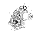
- FIG. 1 is a perspective view of a motor device 1 according to an embodiment of the present invention.
- FIG. 2 is a partial perspective view of the motor device showing a part of the gear unit of FIG. 1 in cross section. It is the fragmentary perspective view which showed the gear housing before installing the pulse output board
- FIG. 6 is a perspective view after the pulse output substrate is installed in FIG. 5. It is the side view which expanded and showed the pulse output board
- substrate is a partial perspective view of the motor device showing a part of the gear unit of FIG.
- FIG. 1 is a perspective view of a motor device 1 according to an embodiment of the present invention.
- the motor device 1 includes a motor 2, a power feeding connector 4, and a gear unit 6.
- the gear unit 6 is, for example, a speed reducer, and the motor device 1 is a DC motor device with a waterproof gear unit. It is used for driving automotive electrical equipment such as electric sliding doors.
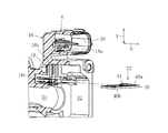
- FIG. 2 is a partial perspective view of the motor device 1 showing a part of the gear unit 6 of FIG. 1 in cross section.
- the motor 2 includes a motor case 8, a drive shaft 10, and an end bell cap 12.
- the motor case 8 has a motor case opening end 14 provided with a flange.
- the drive shaft 10 and the end bell cap 12 protrude from the motor case 8 through a motor case opening end 14 from a completed rotor (not shown).
- the end bell cap 12 is composed of an end bell, a brush holder, a brush, a terminal (all not shown), and the like.
- the power supply connector 4 is resin-molded integrally with a gear housing (housing) 16 described later, and has a plurality of terminals 18 and a bottomed cylindrical connector mounting portion 20.
- the terminals 18 are made of metal and are, for example, four insert-molded in the gear housing 16. From the bottom of the connector mounting portion 20, the connection terminals 18 a of the terminals 18 are directed toward the motor 2 along the axial direction X of the drive shaft 10. Protruding. By attaching an external connector (not shown) to the connector attaching portion 20, it is possible to energize the terminal 18 and thus the pulse output board 22 described later from the connection terminal 18a.
- the gear unit 6 includes a gear housing 16 and a gear train 24 accommodated in the gear housing 16.
- the gear housing 16 has a gear housing opening end 26.
- the drive shaft 10 extends from the motor 2 toward the gear unit 6, and the flange of the motor case opening end 14 is bolted to the gear housing opening end 26 from the axial direction X.
- the gear train 24 includes a worm 28 fixed to the drive shaft 10 and a worm wheel 30 meshed with the worm 28.
- the worm wheel 30 includes an output shaft 31 erected from the center of the wheel main body, and a gear portion 31 a is formed on the outer periphery of the distal end portion of the output shaft 31.
- the gear portion 31a is disposed outside the motor device 1 and meshed with a gear portion of a rotating member (for example, a shaft of a cable drum) connected to a driven device (not shown).
- the rotational driving force of the motor 2 is transmitted to the rotating member, that is, the external driven device via the driving shaft 10 through the worm 28, the worm wheel 30 and the output shaft 31 in order.
- the rotation of the worm wheel 30 may be transmitted to the output shaft 31 via a buffer rubber or the like (not shown).
- a sensor housing portion 32, a shaft housing portion 34, and a gear housing portion 36 are formed in the gear housing 16 as communicating spaces.
- the sensor housing portion 32 is formed at a position adjacent to the power supply connector 4 in the radial direction Y (vertical direction as viewed in FIG. 2) of the drive shaft 10 and is opened by the gear housing opening end 26.
- the end bell cap 12 projecting from the head, the pulse output substrate 22, the sensor magnet 38, which will be described later, and the like are accommodated.
- the shaft accommodating portion 34 extends from the sensor accommodating portion 32 in the direction opposite to the motor 2 along the axial direction X, has a shape whose diameter is reduced from the sensor accommodating portion 32, and accommodates the drive shaft 10, the worm 28, and the like. Yes.
- the gear housing part 36 extends from the shaft housing part 34 along the radial direction Y in the opposite direction to the power supply connector 4 and houses the worm wheel 30 and the like.
- the sensor magnet 38 accommodated in the sensor accommodating portion 32 is formed in an annular shape and fixed to the drive shaft 10 so as to be integrally rotatable, and generates a magnetic flux while rotating integrally with the drive shaft 10.
- the pulse output board 22 is positioned in the sensor housing portion 32 in the vicinity of the sensor magnet 38 so as to face the sensor magnet 38 in the radial direction Y.
- FIG. 3 is a partial perspective view showing a part of the gear housing 16 before the pulse output board 22 is installed
- FIG. 4 is a perspective view after the pulse output board 22 is installed in FIG.
- the pulse output substrate 22 is a single-sided mounting substrate in which patterns, elements, etc. exist only on one side, and has a magnetically permeable base 40.
- a GMR element (rotation detecting element) 41 for detecting the rotation of the sensor magnet 38 based on a change in magnetic flux and an electronic chip such as a capacitor or a diode (not shown) are mounted.
- the GMR element 41 is a giant magnetoresistive element, and is a semiconductor element that utilizes the giant magnetoresistive effect that has a particularly large degree of relative change among the magnetoresistive effects in which the electrical resistance of a substance changes due to a magnetic field.
- a pulse based on the rotation of the magnet 38 is output to a rotation speed control unit (not shown) of the motor 2.
- Each terminal 18 opens to the connection terminal 18a, the vertical part 18b bent in the radial direction Y from the connection terminal 18a and partially embedded in the power supply connector 4, and the sensor housing part 32, and outputs a pulse. And an insertion portion 18c into which the substrate 22 is inserted.
- the insertion portion 18 c moves the pulse output board 22 near the sensor magnet 38 with the back surface 40 b of the mounting surface 40 a of the base 40 facing the sensor magnet 38 as the pulse output board 22 is inserted. (See FIG. 2), and the pulse output substrate 22 is electrically connected to allow the pulse output substrate 22 to be energized.
- FIG. 5 is a partial perspective view showing the gear housing 16 from the gear housing opening end 26 side before the pulse output board 22 is installed
- FIG. 6 is a perspective view after the pulse output board 22 is installed in FIG. FIG.
- each terminal 18 has a contact terminal 42, and the four contact terminals 42 of each terminal 18 are arranged in the radial direction Z of the drive shaft 10 (left and right direction as viewed in FIGS. 5 and 6).
- the insertion portion 18c is formed by sandwiching the mounting surface 40a and the back surface 40b of the pulse output substrate 22 in parallel.
- a substrate guide groove (insertion restricting portion) 43 is formed in the side surface of the sensor housing portion 32 in the gear housing 16.
- the pulse output substrate 22 is accommodated in the sensor accommodating portion 32.
- An abutting portion 43a is formed in the substrate guide groove 43, and when the pulse output substrate 22 is inserted into the substrate guide groove 43, the insertion depth of the pulse output substrate 22 with respect to the insertion portion 18c is limited. That is, the insertion depth of the pulse output substrate 22 with respect to the insertion portion 18 c is defined by the position of the abutting portion 43 a in the substrate guide groove 43.
- FIG. 7 is an enlarged side view showing the pulse output substrate 22 of FIG.
- each contact terminal 42 has a clip shape having an upper movable pin 42a as viewed in FIG. 7 and a lower fixed pin 42b as viewed in FIG.
- the movable pin 42a abuts on the mounting surface 40a, and displacement in a direction away from the fixed pin 42b is allowed to clamp the pulse output substrate 22 between the fixed pin 42b by elastic deformation.
- the fixed pin 42b comes into contact with the back surface 40b and is partially embedded in the gear housing 16 and fixed so as to prevent displacement in a direction away from the movable pin 42a.
- each movable pin 42a is formed with a contact portion 42a2 with respect to the pulse output substrate 22, and the contact portion 42a2 has an arc shape as viewed in FIG.
- the contact area of the movable pin 42a with respect to the pulse output board 22 is reduced, and the pressing force of the movable pin 42a with respect to the mounting surface 40a can be increased, so that the pulse output board 22 is firmly held by the clip-shaped contact terminals 42. It becomes possible.
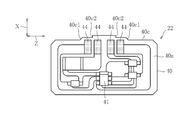
- FIG. 8 is a plan view of the pulse output board 22 as viewed from the mounting surface 40a side.
- the pulse output board 22 has a front end face 40c where the insertion of the pulse output board 22 into the insertion portion 18c is started, and the front end face 40c has an insertion direction of the pulse output board 22 (that is, an axial direction X).
- Two step portions 40c1 and 40c2 that project the front end surface 40c stepwise are provided on the left and right sides.
- the terminal 18 has the insertion portion 18c into which the pulse output substrate 22 is inserted.
- the insertion portion 18c opens to the sensor housing portion 32, and the insertion of the pulse output substrate 22 With the back surface 40b of the mounting surface 40a of the base 40 facing the sensor magnet 38, the pulse output substrate 22 is supported in the vicinity of the sensor magnet 38, and the pulse output substrate 22 is electrically connected and energized.
- the base 40 can prevent the grease and metal foreign matter from being scattered to the pulse output substrate 22 and thus to the GMR element 41. Since the base 40 is made of a magnetically permeable material, the pulse output accuracy from the GMR element 41 is not affected. Thereby, it is not necessary to form a shielding part such as grease on the gear housing 16. Further, since the insertion portion 18c of the pulse output board 22 is formed by the terminal 18, a part such as a sensor holder for fixing and positioning the pulse output board 22 and its locking claw and positioning protrusion is formed in the gear housing 16. do not have to.
- the insertion portion 18c allows the pulse output substrate 22 to be positioned and energized at the same time by sandwiching the mounting surface 40a and the back surface 40b of the pulse output substrate 22 with the contact terminal 42 of the terminal 18.
- the holding of the pulse output substrate 22 by the contact terminal 42 is performed by the movable pin 42a that contacts the mounting surface 40a and the fixed pin 42b that contacts the back surface 40b.
- the movable pin 42a is allowed to be displaced in a direction away from the fixed pin 42b so as to sandwich the pulse output substrate 22 with the fixed pin 42b by elastic deformation, and allows the pulse output substrate 22 to be inserted into the insertion portion 18c. .
- the fixed pin 42b is fixed to the gear housing 16 so as to prevent displacement in a direction away from the movable pin 42a.
- the distance D1 between the back surface 40b and the sensor magnet 38 becomes constant. Since the thickness t of the pulse output substrate 22 is constant, the distance D2 that is the sum of the distance D1 and the thickness t is maintained as the separation distance between the GMR element 41 and the sensor magnet 38.
- the insertion depth of the pulse output substrate 22 with respect to the insertion portion 18c can be defined by the substrate guide groove 43. As a result, it is possible to prevent the pulse output substrate 22 from being pushed too much into the insertion portion 18c and the distance D2 to fluctuate, thereby reducing the pulse output accuracy and hence the rotation speed detection accuracy of the motor 2.
- each electrode portion 44 and the base 40 of the front portion thereof are provided.
- the contact terminals 42 are contacted in stages. Thereby, the insertion load to the pulse output substrate 22 is temporally dispersed, and it is possible to prevent the pulse output substrate 22 from being broken and damaged with the insertion into the insertion portion 18c.
- the present invention is not limited to the above embodiment, and various modifications can be made.
- the insertion portion 18c is formed by the four contact terminals 42 of each terminal 18.
- the number of the terminals 18 and the contact terminals 42 is not limited. It is not limited to that by the terminal 42.
- the GMR element 41 is used for detecting the rotational speed of the sensor magnet 38, but another magnetic sensor (for example, a Hall element) may be used instead of the GMR element 41.
- the pulse output substrate 22 is a single-sided mounting substrate in which the pattern, the 41 GMR elements, and other electronic chips are all present on only one side which is the mounting surface 40a.
- the specification of the pulse output substrate 22 is not limited to this, and it is sufficient that at least the GMR element 41 is mounted on the mounting surface 40a, and an electronic chip other than the pattern and the GMR element 41 exists on the back surface 40b of the mounting surface 40a. May be.
- the stepped portions 40c1 and 40c2 are provided on the front end surface 40c of the pulse output substrate 22.
- the present invention is not limited to this. Instead of providing the stepped portions 40c1 and 40c2 on the front end surface 40c of the pulse output board 22, the length of the movable pin 42a of each contact terminal 42 is changed as shown in FIG.
- the contact part 42a2 may be brought into contact with different positions of the pulse output substrate 22 in stages in the insertion direction of the substrate 22.
- the insertion load on the pulse output substrate 22 by each contact terminal 42 can be dispersed in time to prevent breakage of the pulse output substrate 22 such as breakage. It is.
Abstract
A motor device (1) equipped with: a sensor magnet (38) that rotates integrally with the drive shaft (10) of a motor (2); a housing (16) having a sensor housing section (32) in which the sensor magnet is positioned; a pulse output substrate (22) having a magnetically permeable base (40), and a rotation detection element (41) that is mounted on a mounting surface (40a) of the base, and that detects the rotation of the sensor magnet and outputs a pulse; and a terminal (18) electrically connected to the pulse output substrate. The terminal has an insertion section (18c) into which the pulse output substrate is inserted. The insertion section opens into the sensor housing section, supports the pulse output substrate in the vicinity of the sensor magnet, with the rear surface (40b) of the mounting surface of the base facing the sensor magnet, when the pulse output substrate is inserted, and electrically connects the pulse output substrate.
Description
本発明はモータ装置に関する。
The present invention relates to a motor device.
この種のモータ装置は、駆動軸を有するモータと、駆動軸と一体回転するセンサマグネットと、センサマグネットが位置するセンサ収容部を有するハウジングと、センサマグネットの回転を検出し、パルスを出力するホール素子を有するパルス出力基板とを有するものが知られている。ホール素子は、パルス出力基板のベースの実装面に実装される。
特許文献1には、プリント回路基板のホール効果セルを磁気円盤の直近に隔板等を介することなく対向して位置付けたギアーモータが開示されている。 This type of motor device includes a motor having a drive shaft, a sensor magnet that rotates integrally with the drive shaft, a housing that has a sensor housing in which the sensor magnet is located, a hole that detects rotation of the sensor magnet and outputs a pulse. What has a pulse output board | substrate which has an element is known. The Hall element is mounted on the mounting surface of the base of the pulse output board.
Patent Document 1 discloses a gear motor in which Hall effect cells of a printed circuit board are positioned facing each other without using a partition plate or the like in the immediate vicinity of a magnetic disk.
特許文献1には、プリント回路基板のホール効果セルを磁気円盤の直近に隔板等を介することなく対向して位置付けたギアーモータが開示されている。 This type of motor device includes a motor having a drive shaft, a sensor magnet that rotates integrally with the drive shaft, a housing that has a sensor housing in which the sensor magnet is located, a hole that detects rotation of the sensor magnet and outputs a pulse. What has a pulse output board | substrate which has an element is known. The Hall element is mounted on the mounting surface of the base of the pulse output board.
また、特許文献2には減速機構を備えた小型モータが開示されている。このパルス出力基板は、ホール素子の実装面がセンサマグネットに対向させる向きでセンサホルダに固定されている。また、ホール素子とセンサマグネットとの間には、ハウジングの隔板とセンサホルダの底板とが存在する。また、センサホルダには、パルス出力基板を固定するための係止爪と、パルス出力基板を位置決めするための位置決め突起が設けられている。また、ホール素子にはリード線が半田付け等で接続され、これよりパルス出力基板がパワーウインドウ制御回路と電気的に接続されている。
Patent Document 2 discloses a small motor having a speed reduction mechanism. The pulse output board is fixed to the sensor holder in such a direction that the mounting surface of the Hall element faces the sensor magnet. Further, between the hall element and the sensor magnet, there are a partition plate of the housing and a bottom plate of the sensor holder. The sensor holder is provided with a locking claw for fixing the pulse output board and a positioning projection for positioning the pulse output board. In addition, lead wires are connected to the Hall element by soldering or the like, and thereby the pulse output substrate is electrically connected to the power window control circuit.
上記特許文献1では、ホール素子の実装面がセンサマグネットに対向されている。このため、駆動軸の回転に伴い、駆動軸近傍の摺動部に供給されるグリスが飛散してホール素子に付着すると、ホール素子から出力されるパルスの出力精度が著しく悪化するおそれがある。また、ホール素子とセンサマグネットとの間にグリスに付着した金属異物が介在すると、パルス出力精度のさらなる悪化を招く。
In Patent Document 1, the mounting surface of the Hall element is opposed to the sensor magnet. For this reason, if the grease supplied to the sliding portion in the vicinity of the drive shaft scatters and adheres to the Hall element as the drive shaft rotates, the output accuracy of the pulses output from the Hall element may be significantly deteriorated. In addition, if a metal foreign object attached to the grease is interposed between the Hall element and the sensor magnet, the pulse output accuracy is further deteriorated.
さらには、パルス出力基板に付着したグリス成分によって、パルス出力基板のモールド剤の破壊、腐食、異物ショート等の不具合が生じる懸念もある。そこで、上記特許文献2に示されるように、ホール素子とセンサマグネットとの間にハウジングの隔板とセンサホルダの底板とを位置付けることにより、グリス等からホール素子を保護する構造が考えられる。しかし、これではハウジングの構造が複雑になり、ハウジングひいてはモータの生産性が悪化するおそれがある。
Furthermore, there is a concern that the grease component adhering to the pulse output substrate may cause problems such as destruction of the molding agent on the pulse output substrate, corrosion, and foreign matter short circuit. Therefore, as shown in Patent Document 2, a structure in which the Hall element is protected from grease or the like by positioning the partition plate of the housing and the bottom plate of the sensor holder between the Hall element and the sensor magnet can be considered. However, this complicates the structure of the housing, which may deteriorate the productivity of the housing and thus the motor.
また、ホール素子からのパルス出力精度を確保するためには、センサマグネットに対するパルス出力基板ひいてはホール素子の位置精度を高めなければならない。したがって、上記特許文献2では、パルス出力基板を位置決めするセンサホルダ、及びその係止爪、位置決め突起の寸法精度の厳密な管理が要求され、ハウジングひいてはモータの生産性がさらに悪化しかねない。
Also, in order to ensure the accuracy of pulse output from the Hall element, it is necessary to increase the positional accuracy of the pulse output substrate with respect to the sensor magnet and thus the Hall element. Therefore, in the above-mentioned Patent Document 2, it is required to strictly manage the dimensional accuracy of the sensor holder for positioning the pulse output substrate, its locking claw, and the positioning protrusion, and the productivity of the housing and the motor may be further deteriorated.
また、上記特許文献2において、ホール素子にリード線を半田付けする工程は、モータの組み立て工数を増大し、工程の自動化をも困難にする。また、リード線が引っ張られたりして半田付け部に負荷がかかると、リード線が半田付け部から外れ、パルス出力基板への通電が遮断されることがあり、モータの品質を確保できないおそれもある。
Also, in the above-mentioned Patent Document 2, the process of soldering the lead wire to the Hall element increases the number of steps for assembling the motor and makes it difficult to automate the process. Also, if the lead wire is pulled or a load is applied to the soldering part, the lead wire may come off from the soldering part and the current to the pulse output board may be cut off, which may prevent the motor quality from being ensured. is there.
本発明はこのような課題に鑑みてなされたものであり、その目的とするところは、簡素なハウジングの構造でパルス出力基板によるモータの回転数検出精度を高め、モータの品質及び生産性を向上することができるモータ装置を提供することにある。
The present invention has been made in view of such problems, and the object of the present invention is to improve the motor rotation speed detection accuracy by the pulse output board with a simple housing structure and improve the quality and productivity of the motor. It is providing the motor apparatus which can do.
上記目的を達成するため、本発明のモータ装置は、駆動軸を有するモータと、前記駆動軸と一体回転するセンサマグネットと、前記センサマグネットが位置するセンサ収容部を有するハウジングと、磁気透過性のベース、及び前記ベースの実装面に実装されると共に前記センサマグネットの回転を検出し、パルスを出力する回転検出素子を有するパルス出力基板と、前記パルス出力基板と電気的に接続されるターミナルとを備え、前記ターミナルは、前記パルス出力基板が挿入される挿入部を有し、前記挿入部は、前記センサ収容部に開口し、前記パルス出力基板の挿入に伴い、前記ベースの前記実装面の裏面を前記センサマグネットに対向させた状態で前記パルス出力基板を前記センサマグネット近傍にて支持し、且つ前記パルス出力基板を電気的に接続する。
In order to achieve the above object, a motor device of the present invention includes a motor having a drive shaft, a sensor magnet that rotates integrally with the drive shaft, a housing that has a sensor housing portion in which the sensor magnet is located, A base, a pulse output board mounted on a mounting surface of the base and having a rotation detection element for detecting rotation of the sensor magnet and outputting a pulse; and a terminal electrically connected to the pulse output board. The terminal has an insertion part into which the pulse output board is inserted, and the insertion part opens into the sensor housing part, and the back surface of the mounting surface of the base is inserted along with the insertion of the pulse output board. The pulse output substrate is supported in the vicinity of the sensor magnet with the sensor facing the sensor magnet, and the pulse output base is supported. The electrical connection.
好ましくは、前記ターミナルは、前記パルス出力基板の前記実装面及び前記裏面を挟持することで前記挿入部を形成する接触端子を有する。
好ましくは、前記接触端子は、可動ピンと固定ピンとからなり、前記可動ピンは、弾性変形により前記パルス出力基板を前記固定ピンとの間で挟持するべく前記固定ピンから離間する方向の変位が許容され、一方、前記固定ピンは、前記可動ピンから離間する方向の変位を阻止するべく前記ハウジングに固定されている。 Preferably, the terminal includes a contact terminal that forms the insertion portion by sandwiching the mounting surface and the back surface of the pulse output board.
Preferably, the contact terminal includes a movable pin and a fixed pin, and the movable pin is allowed to be displaced in a direction away from the fixed pin so as to sandwich the pulse output substrate with the fixed pin by elastic deformation. On the other hand, the fixed pin is fixed to the housing to prevent displacement in a direction away from the movable pin.
好ましくは、前記センサ収容部は、前記挿入部に対する前記パルス出力基板の挿入深さを規定する挿入規制部を有する。
好ましくは、前記ターミナルは複数設けられ、前記パルス出力基板には、前記挿入部への前記パルス出力基板の挿入に際し、前記複数のターミナルの前記各接触端子が接触する複数の接触部が形成される。 Preferably, the sensor housing portion includes an insertion restricting portion that defines an insertion depth of the pulse output substrate with respect to the insertion portion.
Preferably, a plurality of the terminals are provided, and the pulse output substrate is formed with a plurality of contact portions that contact the contact terminals of the plurality of terminals when the pulse output substrate is inserted into the insertion portion. .
好ましくは、前記パルス出力基板は、前記挿入部への前記パルス出力基板の挿入が開始される前端面を有し、前記前端面は、前記パルス出力基板の挿入方向に前記前端面を段階的に突出させる段差部を有する。
好ましくは、前記複数のターミナルの前記各可動ピンは、前記パルス出力基板の挿入方向で異なる位置に前記パルス出力基板に対する当接部を有する。 Preferably, the pulse output substrate has a front end surface where insertion of the pulse output substrate into the insertion portion is started, and the front end surface steps the front end surface in the insertion direction of the pulse output substrate. It has a stepped portion that protrudes.
Preferably, each of the movable pins of the plurality of terminals has an abutting portion with respect to the pulse output board at a different position in the insertion direction of the pulse output board.
本発明のモータ装置によれば、簡素なハウジングの構造でパルス出力基板によるモータの回転数検出精度を高め、モータの品質及び生産性を向上することができる。
According to the motor device of the present invention, it is possible to improve the motor rotation speed detection accuracy by the pulse output board with a simple housing structure, and to improve the motor quality and productivity.
以下、図面に基づき本発明の一実施形態について説明する。
図1は本発明の一実施形態に係るモータ装置1の斜視図である。図1に示すように、モータ装置1は、モータ2、給電コネクタ4、及びギヤユニット6を備えている。ギヤユニット6は例えば減速機であって、モータ装置1は、防水仕様のギヤユニット付き直流モータ装置であり、自動車の窓ガラスを自動的に開閉するパワーウインドウ、車体の天井部に取り付けられる電動サンルーフ、電動スライドドア等の自動車用電装機器の駆動に用いられる。 Hereinafter, an embodiment of the present invention will be described with reference to the drawings.
FIG. 1 is a perspective view of amotor device 1 according to an embodiment of the present invention. As shown in FIG. 1, the motor device 1 includes a motor 2, a power feeding connector 4, and a gear unit 6. The gear unit 6 is, for example, a speed reducer, and the motor device 1 is a DC motor device with a waterproof gear unit. It is used for driving automotive electrical equipment such as electric sliding doors.
図1は本発明の一実施形態に係るモータ装置1の斜視図である。図1に示すように、モータ装置1は、モータ2、給電コネクタ4、及びギヤユニット6を備えている。ギヤユニット6は例えば減速機であって、モータ装置1は、防水仕様のギヤユニット付き直流モータ装置であり、自動車の窓ガラスを自動的に開閉するパワーウインドウ、車体の天井部に取り付けられる電動サンルーフ、電動スライドドア等の自動車用電装機器の駆動に用いられる。 Hereinafter, an embodiment of the present invention will be described with reference to the drawings.
FIG. 1 is a perspective view of a
図2は、図1のギヤユニット6の一部を断面で示したモータ装置1の部分的な斜視図である。図2に示すように、モータ2は、モータケース8、駆動軸10、及びエンドベルキャップ12を備えている。モータケース8は、フランジが設けられたモータケース開口端14を有している。駆動軸10及びエンドベルキャップ12は、図示しない完成ロータからモータケース開口端14を通じてモータケース8から突出されている。
FIG. 2 is a partial perspective view of the motor device 1 showing a part of the gear unit 6 of FIG. 1 in cross section. As shown in FIG. 2, the motor 2 includes a motor case 8, a drive shaft 10, and an end bell cap 12. The motor case 8 has a motor case opening end 14 provided with a flange. The drive shaft 10 and the end bell cap 12 protrude from the motor case 8 through a motor case opening end 14 from a completed rotor (not shown).
エンドベルキャップ12は、エンドベル、ブラシホルダ、ブラシ、ターミナル(何れも図示しない)等から構成されている。給電コネクタ4は、後述するギヤハウジング(ハウジング)16と一体に樹脂成形され、複数のターミナル18と有底円筒形状のコネクタ取付部20とを有している。
The end bell cap 12 is composed of an end bell, a brush holder, a brush, a terminal (all not shown), and the like. The power supply connector 4 is resin-molded integrally with a gear housing (housing) 16 described later, and has a plurality of terminals 18 and a bottomed cylindrical connector mounting portion 20.
ターミナル18は、金属製であってギヤハウジング16に例えば4つインサート成形され、コネクタ取付部20の底からは各ターミナル18の接続端子18aが駆動軸10の軸線方向Xに沿ってモータ2に向けて突出されている。コネクタ取付部20に図示しない外部のコネクタを取り付けることにより、接続端子18aからターミナル18ひいては後述するパルス出力基板22に通電することができる。
The terminals 18 are made of metal and are, for example, four insert-molded in the gear housing 16. From the bottom of the connector mounting portion 20, the connection terminals 18 a of the terminals 18 are directed toward the motor 2 along the axial direction X of the drive shaft 10. Protruding. By attaching an external connector (not shown) to the connector attaching portion 20, it is possible to energize the terminal 18 and thus the pulse output board 22 described later from the connection terminal 18a.
ギヤユニット6は、ギヤハウジング16とギヤハウジング16に収容されるギヤ列24とを備えている。ギヤハウジング16は、ギヤハウジング開口端26を有している。モータ2からは、ギヤユニット6に向けて駆動軸10が延び、ギヤハウジング開口端26には、モータケース開口端14のフランジが軸線方向Xからボルト結合される。ギヤ列24は、駆動軸10に固定されたウォーム28と、ウォーム28に噛み合わされるウォームホイール30とから構成されている。
The gear unit 6 includes a gear housing 16 and a gear train 24 accommodated in the gear housing 16. The gear housing 16 has a gear housing opening end 26. The drive shaft 10 extends from the motor 2 toward the gear unit 6, and the flange of the motor case opening end 14 is bolted to the gear housing opening end 26 from the axial direction X. The gear train 24 includes a worm 28 fixed to the drive shaft 10 and a worm wheel 30 meshed with the worm 28.
図1に示すように、ウォームホイール30は、ホイール本体の中央から立設された出力軸31を備え、出力軸31の先端部にはその外周にギヤ部31aが形成されている。ギヤ部31aは、モータ装置1の外部に配置され且つ図示しない被駆動装置と連結された回転部材(例えば、ケーブルドラムの軸)のギヤ部と噛み合わされる。
As shown in FIG. 1, the worm wheel 30 includes an output shaft 31 erected from the center of the wheel main body, and a gear portion 31 a is formed on the outer periphery of the distal end portion of the output shaft 31. The gear portion 31a is disposed outside the motor device 1 and meshed with a gear portion of a rotating member (for example, a shaft of a cable drum) connected to a driven device (not shown).
こうして、モータ2の回転駆動力は、駆動軸10を介して、ウォーム28、ウォームホイール30、出力軸31を順次経て回転部材、すなわち、外部の被駆動装置に伝達される。なお、ウォームホイール30の回転は図示しない緩衝ラバー等を介して出力軸31に伝達されても良い。
Thus, the rotational driving force of the motor 2 is transmitted to the rotating member, that is, the external driven device via the driving shaft 10 through the worm 28, the worm wheel 30 and the output shaft 31 in order. The rotation of the worm wheel 30 may be transmitted to the output shaft 31 via a buffer rubber or the like (not shown).
図2に示すように、ギヤハウジング16内には、連通した空間として、センサ収容部32、軸収容部34、及びギヤ収容部36が形成されている。センサ収容部32は、駆動軸10の径方向Y(図2で見て上下方向)で給電コネクタ4に隣接する位置に形成され、ギヤハウジング開口端26により開口されており、モータケース開口端14から突出したエンドベルキャップ12、パルス出力基板22、及び後述するセンサマグネット38等が収容されている。
As shown in FIG. 2, a sensor housing portion 32, a shaft housing portion 34, and a gear housing portion 36 are formed in the gear housing 16 as communicating spaces. The sensor housing portion 32 is formed at a position adjacent to the power supply connector 4 in the radial direction Y (vertical direction as viewed in FIG. 2) of the drive shaft 10 and is opened by the gear housing opening end 26. The end bell cap 12 projecting from the head, the pulse output substrate 22, the sensor magnet 38, which will be described later, and the like are accommodated.
軸収容部34は、センサ収容部32から軸線方向Xに沿ってモータ2と反対方向に延び、センサ収容部32から縮径された形状を有し、駆動軸10及びウォーム28等が収容されている。ギヤ収容部36は、軸収容部34から径方向Yに沿って給電コネクタ4と反対方向に延び、ウォームホイール30等が収容されている。
The shaft accommodating portion 34 extends from the sensor accommodating portion 32 in the direction opposite to the motor 2 along the axial direction X, has a shape whose diameter is reduced from the sensor accommodating portion 32, and accommodates the drive shaft 10, the worm 28, and the like. Yes. The gear housing part 36 extends from the shaft housing part 34 along the radial direction Y in the opposite direction to the power supply connector 4 and houses the worm wheel 30 and the like.
センサ収容部32内に収容されたセンサマグネット38は、環状に形成されて駆動軸10に一体回転可能に固定され、駆動軸10と一体回転しつつ磁束を発生する。パルス出力基板22は、センサ収容部32内でセンサマグネット38近傍にて、センサマグネット38に径方向Yで対向して位置付けられている。
The sensor magnet 38 accommodated in the sensor accommodating portion 32 is formed in an annular shape and fixed to the drive shaft 10 so as to be integrally rotatable, and generates a magnetic flux while rotating integrally with the drive shaft 10. The pulse output board 22 is positioned in the sensor housing portion 32 in the vicinity of the sensor magnet 38 so as to face the sensor magnet 38 in the radial direction Y.
図3はパルス出力基板22を設置する前のギヤハウジング16を一部断面で示した部分的な斜視図であり、図4は図3にてパルス出力基板22を設置した後の斜視図である。図3に示すように、パルス出力基板22は、パターン及び素子等が片面のみに存在する片面実装基板であり、磁気透過性のベース40を有している。ベース40の実装面40aには、センサマグネット38の回転を磁束の変化に基づいて検出するGMR素子(回転検出素子)41及び図示しないコンデンサやダイオード等の電子チップが実装されている。
FIG. 3 is a partial perspective view showing a part of the gear housing 16 before the pulse output board 22 is installed, and FIG. 4 is a perspective view after the pulse output board 22 is installed in FIG. . As shown in FIG. 3, the pulse output substrate 22 is a single-sided mounting substrate in which patterns, elements, etc. exist only on one side, and has a magnetically permeable base 40. On the mounting surface 40a of the base 40, a GMR element (rotation detecting element) 41 for detecting the rotation of the sensor magnet 38 based on a change in magnetic flux and an electronic chip such as a capacitor or a diode (not shown) are mounted.
GMR素子41は巨大磁気抵抗素子であって、磁場により物質の電気抵抗が変化する磁気抵抗効果の中でも、特にその相対変化の度合いが大きい巨大磁気抵抗効果を利用した半導体素子であり、検出したセンサマグネット38の回転に基づくパルスをモータ2の図示しない回転数制御部に出力する。各ターミナル18は、前述した接続端子18aと、接続端子18aから径方向Yに屈曲されると共に給電コネクタ4内に一部が埋め込まれた垂直部18bと、センサ収容部32に開口し、パルス出力基板22が挿入される挿入部18cとを有している。
The GMR element 41 is a giant magnetoresistive element, and is a semiconductor element that utilizes the giant magnetoresistive effect that has a particularly large degree of relative change among the magnetoresistive effects in which the electrical resistance of a substance changes due to a magnetic field. A pulse based on the rotation of the magnet 38 is output to a rotation speed control unit (not shown) of the motor 2. Each terminal 18 opens to the connection terminal 18a, the vertical part 18b bent in the radial direction Y from the connection terminal 18a and partially embedded in the power supply connector 4, and the sensor housing part 32, and outputs a pulse. And an insertion portion 18c into which the substrate 22 is inserted.
図4に示すように、挿入部18cは、パルス出力基板22の挿入に伴い、ベース40の実装面40aの裏面40bをセンサマグネット38に対向させた状態でパルス出力基板22をセンサマグネット38近傍にて支持し(図2参照)、且つパルス出力基板22を電気的に接続してパルス出力基板22への通電を可能としている。
As shown in FIG. 4, the insertion portion 18 c moves the pulse output board 22 near the sensor magnet 38 with the back surface 40 b of the mounting surface 40 a of the base 40 facing the sensor magnet 38 as the pulse output board 22 is inserted. (See FIG. 2), and the pulse output substrate 22 is electrically connected to allow the pulse output substrate 22 to be energized.
図5はパルス出力基板22を設置する前のギヤハウジング16をギヤハウジング開口端26側から示した部分的な斜視図であり、図6は図5にてパルス出力基板22を設置した後の斜視図である。図5及び図6に示すように、各ターミナル18は接触端子42を有し、各ターミナル18の4つの接触端子42は、駆動軸10の径方向Z(図5及び図6で見て左右方向)に並列され、パルス出力基板22の実装面40a及び裏面40bを挟持することで挿入部18cを形成している。
FIG. 5 is a partial perspective view showing the gear housing 16 from the gear housing opening end 26 side before the pulse output board 22 is installed, and FIG. 6 is a perspective view after the pulse output board 22 is installed in FIG. FIG. As shown in FIGS. 5 and 6, each terminal 18 has a contact terminal 42, and the four contact terminals 42 of each terminal 18 are arranged in the radial direction Z of the drive shaft 10 (left and right direction as viewed in FIGS. 5 and 6). The insertion portion 18c is formed by sandwiching the mounting surface 40a and the back surface 40b of the pulse output substrate 22 in parallel.
図5に示すように、ギヤハウジング16には、センサ収容部32の側面に基板ガイド溝(挿入規制部)43が形成されている。パルス出力基板22を基板ガイド溝43に挿入することにより、センサ収容部32に収容される。基板ガイド溝43には突き当て部43aが形成され、基板ガイド溝43までパルス出力基板22が挿入されると、挿入部18cに対するパルス出力基板22の挿入深さが制限される。すなわち、基板ガイド溝43における突き当て部43aの位置により挿入部18cに対するパルス出力基板22の挿入深さが規定される。
As shown in FIG. 5, a substrate guide groove (insertion restricting portion) 43 is formed in the side surface of the sensor housing portion 32 in the gear housing 16. By inserting the pulse output substrate 22 into the substrate guide groove 43, the pulse output substrate 22 is accommodated in the sensor accommodating portion 32. An abutting portion 43a is formed in the substrate guide groove 43, and when the pulse output substrate 22 is inserted into the substrate guide groove 43, the insertion depth of the pulse output substrate 22 with respect to the insertion portion 18c is limited. That is, the insertion depth of the pulse output substrate 22 with respect to the insertion portion 18 c is defined by the position of the abutting portion 43 a in the substrate guide groove 43.
図7は図2のパルス出力基板22を拡大して示した側面図である。図7にも示すように、各接触端子42は、図7で見て上側の可動ピン42aと、図7で見て下側の固定ピン42bとを有するクリップ形状をなしている。可動ピン42aは、実装面40aに当接し、弾性変形によりパルス出力基板22を固定ピン42bとの間で挟持するべく固定ピン42bから離間する方向の変位が許容されている。一方、固定ピン42bは、裏面40bに当接し、可動ピン42aから離間する方向の変位を阻止するべくギヤハウジング16に一部が埋設されて固定されている。
FIG. 7 is an enlarged side view showing the pulse output substrate 22 of FIG. As shown in FIG. 7, each contact terminal 42 has a clip shape having an upper movable pin 42a as viewed in FIG. 7 and a lower fixed pin 42b as viewed in FIG. The movable pin 42a abuts on the mounting surface 40a, and displacement in a direction away from the fixed pin 42b is allowed to clamp the pulse output substrate 22 between the fixed pin 42b by elastic deformation. On the other hand, the fixed pin 42b comes into contact with the back surface 40b and is partially embedded in the gear housing 16 and fixed so as to prevent displacement in a direction away from the movable pin 42a.
また、各可動ピン42aにはパルス出力基板22に対する当接部42a2が形成され、当接部42a2は図7で見て円弧状をなしている。これにより、パルス出力基板22に対する可動ピン42aの接触面積が小さくなり、実装面40aに対する可動ピン42aの押圧力を高めることができるため、クリップ形状の接触端子42によりパルス出力基板22をしっかりと挟持可能となる。
Further, each movable pin 42a is formed with a contact portion 42a2 with respect to the pulse output substrate 22, and the contact portion 42a2 has an arc shape as viewed in FIG. As a result, the contact area of the movable pin 42a with respect to the pulse output board 22 is reduced, and the pressing force of the movable pin 42a with respect to the mounting surface 40a can be increased, so that the pulse output board 22 is firmly held by the clip-shaped contact terminals 42. It becomes possible.
図8はパルス出力基板22を実装面40a側から見た平面図である。図8に示すように、パルス出力基板22の実装面40aには、挿入部18cへのパルス出力基板22の挿入に際し各接触端子42の可動ピン42aが接触する電極部(接触部)44が4つ形成されている。また、パルス出力基板22は、挿入部18cへのパルス出力基板22の挿入が開始される前端面40cを有し、この前端面40cには、パルス出力基板22の挿入方向(すなわち軸線方向X)に前端面40cを段階的に突出させる2つの段差部40c1、40c2を左右両側に有している。
FIG. 8 is a plan view of the pulse output board 22 as viewed from the mounting surface 40a side. As shown in FIG. 8, on the mounting surface 40a of the pulse output board 22, there are four electrode parts (contact parts) 44 with which the movable pins 42a of the contact terminals 42 come into contact when the pulse output board 22 is inserted into the insertion part 18c. One is formed. The pulse output board 22 has a front end face 40c where the insertion of the pulse output board 22 into the insertion portion 18c is started, and the front end face 40c has an insertion direction of the pulse output board 22 (that is, an axial direction X). Two step portions 40c1 and 40c2 that project the front end surface 40c stepwise are provided on the left and right sides.
以上のように本実施形態では、ターミナル18はパルス出力基板22が挿入される挿入部18cを有し、この挿入部18cは、センサ収容部32に開口し、パルス出力基板22の挿入に伴い、ベース40の実装面40aの裏面40bをセンサマグネット38に対向させた状態でパルス出力基板22をセンサマグネット38近傍にて支持し、且つパルス出力基板22を電気的に接続して通電する。
As described above, in the present embodiment, the terminal 18 has the insertion portion 18c into which the pulse output substrate 22 is inserted. The insertion portion 18c opens to the sensor housing portion 32, and the insertion of the pulse output substrate 22 With the back surface 40b of the mounting surface 40a of the base 40 facing the sensor magnet 38, the pulse output substrate 22 is supported in the vicinity of the sensor magnet 38, and the pulse output substrate 22 is electrically connected and energized.
これにより、パルス出力基板22ひいてはGMR素子41へのグリス及び金属異物の飛散をベース40により遮蔽することができる。ベース40は磁気透過性材料から形成されるため、GMR素子41からのパルス出力精度に影響はない。これにより、ギヤハウジング16にグリス等の遮蔽部を形成する必要はない。また、ターミナル18によりパルス出力基板22の挿入部18cが形成されるため、パルス出力基板22を固定して位置決めするためのセンサホルダ、その係止爪、位置決め突起等の部位をギヤハウジング16に形成する必要はない。
Thereby, the base 40 can prevent the grease and metal foreign matter from being scattered to the pulse output substrate 22 and thus to the GMR element 41. Since the base 40 is made of a magnetically permeable material, the pulse output accuracy from the GMR element 41 is not affected. Thereby, it is not necessary to form a shielding part such as grease on the gear housing 16. Further, since the insertion portion 18c of the pulse output board 22 is formed by the terminal 18, a part such as a sensor holder for fixing and positioning the pulse output board 22 and its locking claw and positioning protrusion is formed in the gear housing 16. do not have to.
また、挿入部18cへのパルス出力基板22の挿入だけでパルス出力基板22への給電と、パルス出力基板22に実装されるGMR素子41等からのパルスを外部へ出力することが可能であることから、パルス出力基板22へのリード線の半田付け工程を削減することができ、また、挿入部18cへのパルス出力基板22の挿入は自動化が容易に可能である。したがって、簡素なギヤハウジング16の構造でパルス出力基板22によるモータ2の回転数検出精度を高め、モータ2の品質及び生産性を向上することができる。
Moreover, it is possible to supply power to the pulse output board 22 and output pulses from the GMR element 41 mounted on the pulse output board 22 to the outside simply by inserting the pulse output board 22 into the insertion portion 18c. Therefore, the soldering process of the lead wire to the pulse output board 22 can be reduced, and the insertion of the pulse output board 22 into the insertion portion 18c can be easily automated. Therefore, it is possible to improve the accuracy of detecting the number of revolutions of the motor 2 by the pulse output board 22 with a simple structure of the gear housing 16, and to improve the quality and productivity of the motor 2.
より詳しくは、挿入部18cはターミナル18の接触端子42でパルス出力基板22の実装面40a及び裏面40bを挟持することでパルス出力基板22の位置決め及び通電を同時に可能とする。接触端子42によるパルス出力基板22の挟持は、実装面40aに接触する可動ピン42aと、裏面40bに接触する固定ピン42bとで行われる。可動ピン42aは、弾性変形によりパルス出力基板22を固定ピン42bとの間で挟持するべく固定ピン42bから離間する方向の変位が許容され、挿入部18cへのパルス出力基板22の挿入を許容する。
More specifically, the insertion portion 18c allows the pulse output substrate 22 to be positioned and energized at the same time by sandwiching the mounting surface 40a and the back surface 40b of the pulse output substrate 22 with the contact terminal 42 of the terminal 18. The holding of the pulse output substrate 22 by the contact terminal 42 is performed by the movable pin 42a that contacts the mounting surface 40a and the fixed pin 42b that contacts the back surface 40b. The movable pin 42a is allowed to be displaced in a direction away from the fixed pin 42b so as to sandwich the pulse output substrate 22 with the fixed pin 42b by elastic deformation, and allows the pulse output substrate 22 to be inserted into the insertion portion 18c. .
一方、固定ピン42bは、可動ピン42aから離間する方向の変位を阻止するべくギヤハウジング16に固定される。これにより、図7に示すように、裏面40bとセンサマグネット38との距離D1が一定となる。パルス出力基板22の厚みtは一定であることから、距離D1と厚みtとの合計の一定となる距離D2がGMR素子41とセンサマグネット38との離間距離として維持される。
On the other hand, the fixed pin 42b is fixed to the gear housing 16 so as to prevent displacement in a direction away from the movable pin 42a. Thereby, as shown in FIG. 7, the distance D1 between the back surface 40b and the sensor magnet 38 becomes constant. Since the thickness t of the pulse output substrate 22 is constant, the distance D2 that is the sum of the distance D1 and the thickness t is maintained as the separation distance between the GMR element 41 and the sensor magnet 38.
また、基板ガイド溝43により、挿入部18cに対するパルス出力基板22の挿入深さを規定可能である。これにより、挿入部18cにパルス出力基板22が押し込まれ過ぎたりして距離D2が変動し、パルス出力精度ひいてはモータ2の回転数検出精度が低下するのを防止することができる。
Further, the insertion depth of the pulse output substrate 22 with respect to the insertion portion 18c can be defined by the substrate guide groove 43. As a result, it is possible to prevent the pulse output substrate 22 from being pushed too much into the insertion portion 18c and the distance D2 to fluctuate, thereby reducing the pulse output accuracy and hence the rotation speed detection accuracy of the motor 2.
また、パルス出力基板22の前端面40cに段差部40c1、40c2が形成されることにより、挿入部18cへのパルス出力基板22の挿入の際、各電極部44及びその前側の部分のベース40に対し各接触端子42が段階的に接触される。これにより、パルス出力基板22への挿入荷重が時間的に分散され、挿入部18cへの挿入に伴いパルス出力基板22が割れて破損するのを防止することができる。
Further, since the stepped portions 40c1 and 40c2 are formed on the front end surface 40c of the pulse output substrate 22, when the pulse output substrate 22 is inserted into the insertion portion 18c, each electrode portion 44 and the base 40 of the front portion thereof are provided. The contact terminals 42 are contacted in stages. Thereby, the insertion load to the pulse output substrate 22 is temporally dispersed, and it is possible to prevent the pulse output substrate 22 from being broken and damaged with the insertion into the insertion portion 18c.
本発明は上記実施形態に制約されるものではなく、種々の変形が可能である。
例えば、上記実施形態では、各ターミナル18の4つの接触端子42により挿入部18cを形成しているが、ターミナル18ひいては接触端子42の数は限定されないし、挿入部18cの態様はクリップ形状の接触端子42によるものに限定されない。
また、上記実施形態では、センサマグネット38の回転数検出にGMR素子41を使用しているが、GMR素子41の代わりに他の磁気センサ(例えばホール素子)を用いても良い。 The present invention is not limited to the above embodiment, and various modifications can be made.
For example, in the above-described embodiment, theinsertion portion 18c is formed by the four contact terminals 42 of each terminal 18. However, the number of the terminals 18 and the contact terminals 42 is not limited. It is not limited to that by the terminal 42.
In the above embodiment, theGMR element 41 is used for detecting the rotational speed of the sensor magnet 38, but another magnetic sensor (for example, a Hall element) may be used instead of the GMR element 41.
例えば、上記実施形態では、各ターミナル18の4つの接触端子42により挿入部18cを形成しているが、ターミナル18ひいては接触端子42の数は限定されないし、挿入部18cの態様はクリップ形状の接触端子42によるものに限定されない。
また、上記実施形態では、センサマグネット38の回転数検出にGMR素子41を使用しているが、GMR素子41の代わりに他の磁気センサ(例えばホール素子)を用いても良い。 The present invention is not limited to the above embodiment, and various modifications can be made.
For example, in the above-described embodiment, the
In the above embodiment, the
また、上記実施形態では、パルス出力基板22は、パターン、GMR素子41素子、及び他の電子チップがすべて実装面40aである片面のみに存在する片面実装基板である。しかし、これに限らず、パルス出力基板22の仕様は、少なくともGMR素子41が実装面40aに実装されていれば良く、パターン及びGMR素子41以外の電子チップが実装面40aの裏面40bに存在しても良い。
In the above-described embodiment, the pulse output substrate 22 is a single-sided mounting substrate in which the pattern, the 41 GMR elements, and other electronic chips are all present on only one side which is the mounting surface 40a. However, the specification of the pulse output substrate 22 is not limited to this, and it is sufficient that at least the GMR element 41 is mounted on the mounting surface 40a, and an electronic chip other than the pattern and the GMR element 41 exists on the back surface 40b of the mounting surface 40a. May be.
また、上記実施形態では、パルス出力基板22の前端面40cに段差部40c1、40c2を設けている。しかし、これに限らず、パルス出力基板22の前端面40cに段差部40c1、40c2を設ける代わりに、図9に示すように、各接触端子42の可動ピン42aの長さを変更し、パルス出力基板22の挿入方向で当接部42a2をパルス出力基板22の異なる位置に段階的に当接させても良い。この場合にも、段差部40c1、40c2を設けた場合と同様に、各接触端子42によるパルス出力基板22への挿入荷重を時間的に分散し、パルス出力基板22の割れ等の破損を防止可能である。
In the above embodiment, the stepped portions 40c1 and 40c2 are provided on the front end surface 40c of the pulse output substrate 22. However, the present invention is not limited to this. Instead of providing the stepped portions 40c1 and 40c2 on the front end surface 40c of the pulse output board 22, the length of the movable pin 42a of each contact terminal 42 is changed as shown in FIG. The contact part 42a2 may be brought into contact with different positions of the pulse output substrate 22 in stages in the insertion direction of the substrate 22. Also in this case, similarly to the case where the stepped portions 40c1 and 40c2 are provided, the insertion load on the pulse output substrate 22 by each contact terminal 42 can be dispersed in time to prevent breakage of the pulse output substrate 22 such as breakage. It is.
1 モータ装置
2 モータ
10 駆動軸
16 ギヤハウジング(ハウジング)
18 ターミナル
18c 挿入部
22 パルス出力基板
32 センサ収容部
38 センサマグネット
40 ベース
40a 実装面
40b 裏面
40c 前端面
40c1、40c2 段差部
41 GMR素子(回転検出素子)
42 接触端子
42a 可動ピン
42b 固定ピン
43 基板ガイド溝(挿入規制部)
42a2 当接部
44 電極部(接触部)
DESCRIPTION OFSYMBOLS 1 Motor apparatus 2 Motor 10 Drive shaft 16 Gear housing (housing)
18Terminal 18c Insertion part 22 Pulse output board 32 Sensor accommodation part 38 Sensor magnet 40 Base 40a Mounting surface 40b Back surface 40c Front end surface 40c1, 40c2 Step part 41 GMR element (rotation detection element)
42Contact terminal 42a Movable pin 42b Fixed pin 43 Substrate guide groove (insertion restricting portion)
42a2 Contactpart 44 Electrode part (contact part)
2 モータ
10 駆動軸
16 ギヤハウジング(ハウジング)
18 ターミナル
18c 挿入部
22 パルス出力基板
32 センサ収容部
38 センサマグネット
40 ベース
40a 実装面
40b 裏面
40c 前端面
40c1、40c2 段差部
41 GMR素子(回転検出素子)
42 接触端子
42a 可動ピン
42b 固定ピン
43 基板ガイド溝(挿入規制部)
42a2 当接部
44 電極部(接触部)
DESCRIPTION OF
18
42
42a2 Contact
Claims (7)
- 駆動軸を有するモータと、
前記駆動軸と一体回転するセンサマグネットと、
前記センサマグネットが位置するセンサ収容部を有するハウジングと、
磁気透過性のベース、及び前記ベースの実装面に実装されると共に前記センサマグネットの回転を検出し、パルスを出力する回転検出素子を有するパルス出力基板と、
前記パルス出力基板と電気的に接続されるターミナルと
を備え、
前記ターミナルは、前記パルス出力基板が挿入される挿入部を有し、
前記挿入部は、前記センサ収容部に開口し、前記パルス出力基板の挿入に伴い、前記ベースの前記実装面の裏面を前記センサマグネットに対向させた状態で前記パルス出力基板を前記センサマグネット近傍にて支持し、且つ前記パルス出力基板を電気的に接続する、モータ装置。 A motor having a drive shaft;
A sensor magnet that rotates integrally with the drive shaft;
A housing having a sensor housing portion in which the sensor magnet is located;
A magnetically permeable base, and a pulse output board that is mounted on the mounting surface of the base and has a rotation detection element that detects rotation of the sensor magnet and outputs a pulse;
A terminal electrically connected to the pulse output substrate;
The terminal has an insertion part into which the pulse output substrate is inserted,
The insertion portion opens to the sensor housing portion, and the pulse output substrate is placed near the sensor magnet with the back surface of the mounting surface of the base facing the sensor magnet as the pulse output substrate is inserted. And a motor device for electrically connecting the pulse output substrate. - 前記ターミナルは、前記パルス出力基板の前記実装面及び前記裏面を挟持することで前記挿入部を形成する接触端子を有する、請求項1に記載のモータ装置。 The motor device according to claim 1, wherein the terminal includes a contact terminal that forms the insertion portion by sandwiching the mounting surface and the back surface of the pulse output board.
- 前記接触端子は、可動ピンと固定ピンとからなり、
前記可動ピンは、弾性変形により前記パルス出力基板を前記固定ピンとの間で挟持するべく前記固定ピンから離間する方向の変位が許容され、一方、前記固定ピンは、前記可動ピンから離間する方向の変位を阻止するべく前記ハウジングに固定されている、請求項2に記載のモータ装置。 The contact terminal comprises a movable pin and a fixed pin,
The movable pin is allowed to be displaced in a direction away from the fixed pin so as to sandwich the pulse output substrate between the fixed pin and elastically deformed, while the fixed pin is in a direction away from the movable pin. The motor device according to claim 2, wherein the motor device is fixed to the housing to prevent displacement. - 前記センサ収容部は、前記挿入部に対する前記パルス出力基板の挿入深さを規定する挿入規制部を有する、請求項3に記載のモータ装置。 The motor device according to claim 3, wherein the sensor housing portion includes an insertion restricting portion that defines an insertion depth of the pulse output substrate with respect to the insertion portion.
- 前記ターミナルは複数設けられ、
前記パルス出力基板には、前記挿入部への前記パルス出力基板の挿入に際し、前記複数のターミナルの前記各接触端子が接触する複数の接触部が形成される、請求項3又は4に記載のモータ装置。 A plurality of the terminals are provided,
5. The motor according to claim 3, wherein the pulse output substrate is formed with a plurality of contact portions that contact the contact terminals of the plurality of terminals when the pulse output substrate is inserted into the insertion portion. apparatus. - 前記パルス出力基板は、前記挿入部への前記パルス出力基板の挿入が開始される前端面を有し、
前記前端面は、前記パルス出力基板の挿入方向に前記前端面を段階的に突出させる段差部を有する、請求項5に記載のモータ装置。 The pulse output substrate has a front end surface where insertion of the pulse output substrate into the insertion portion is started,
The motor device according to claim 5, wherein the front end surface has a stepped portion that projects the front end surface stepwise in an insertion direction of the pulse output substrate. - 前記複数のターミナルの前記各可動ピンは、前記パルス出力基板の挿入方向で異なる位置に前記パルス出力基板に対する当接部を有する、請求項5に記載のモータ装置。
6. The motor device according to claim 5, wherein each of the movable pins of the plurality of terminals has a contact portion with respect to the pulse output board at a different position in an insertion direction of the pulse output board.
Priority Applications (3)
| Application Number | Priority Date | Filing Date | Title |
|---|---|---|---|
| DE112016000903.8T DE112016000903B4 (en) | 2015-02-25 | 2016-01-26 | engine device |
| US15/549,112 US10447118B2 (en) | 2015-02-25 | 2016-01-26 | Motor apparatus |
| CN201680004570.5A CN107112863B (en) | 2015-02-25 | 2016-01-26 | Electric machine |
Applications Claiming Priority (2)
| Application Number | Priority Date | Filing Date | Title |
|---|---|---|---|
| JP2015035271A JP6319848B2 (en) | 2015-02-25 | 2015-02-25 | Motor equipment |
| JP2015-035271 | 2015-02-25 |
Publications (1)
| Publication Number | Publication Date |
|---|---|
| WO2016136362A1 true WO2016136362A1 (en) | 2016-09-01 |
Family
ID=56788409
Family Applications (1)
| Application Number | Title | Priority Date | Filing Date |
|---|---|---|---|
| PCT/JP2016/052169 WO2016136362A1 (en) | 2015-02-25 | 2016-01-26 | Motor device |
Country Status (5)
| Country | Link |
|---|---|
| US (1) | US10447118B2 (en) |
| JP (1) | JP6319848B2 (en) |
| CN (1) | CN107112863B (en) |
| DE (1) | DE112016000903B4 (en) |
| WO (1) | WO2016136362A1 (en) |
Families Citing this family (3)
| Publication number | Priority date | Publication date | Assignee | Title |
|---|---|---|---|---|
| JP7134650B2 (en) | 2018-03-08 | 2022-09-12 | ミネベアミツミ株式会社 | Rotating device, mounting structure of rotating device, and connection structure between rotating device and external connector |
| CN110620303B (en) * | 2018-09-30 | 2021-05-18 | 中航光电科技股份有限公司 | Connector assembly and socket connector thereof |
| DE102019102536A1 (en) * | 2019-02-01 | 2020-08-06 | Nidec Motors & Actuators (Germany) Gmbh | Adjustment drive comprising a brush card arrangement with an integrated printed circuit board |
Citations (6)
| Publication number | Priority date | Publication date | Assignee | Title |
|---|---|---|---|---|
| JPH02199780A (en) * | 1989-01-30 | 1990-08-08 | Yazaki Corp | Low inserting force terminal |
| JPH05115148A (en) * | 1991-10-22 | 1993-05-07 | Mabuchi Motor Co Ltd | Small motor |
| JPH11215774A (en) * | 1998-01-26 | 1999-08-06 | Mitsuba Corp | Electrically driven motor with rotation detection device |
| JP2004166481A (en) * | 2002-09-17 | 2004-06-10 | Asmo Co Ltd | Motor and power window motor |
| JP2008167052A (en) * | 2006-12-27 | 2008-07-17 | Sanyo Electric Co Ltd | Circuit device, and digital broadcast receiver |
| JP2014130755A (en) * | 2012-12-28 | 2014-07-10 | Japan Aviation Electronics Industry Ltd | Connector |
Family Cites Families (8)
| Publication number | Priority date | Publication date | Assignee | Title |
|---|---|---|---|---|
| JPS63235812A (en) * | 1987-03-25 | 1988-09-30 | Hitachi Ltd | Magnetic encoder |
| FR2765043B1 (en) | 1997-06-24 | 2001-02-16 | Rockwell Lvs | MOTOR GEAR ACTIVATION OF A MOTOR VEHICLE FUNCTIONAL |
| JP4121108B2 (en) | 2001-05-31 | 2008-07-23 | 株式会社ミツバ | Small motor |
| DE10342756B4 (en) | 2002-09-17 | 2016-10-06 | Asmo Co., Ltd. | Motor with a connector housing |
| US7187095B2 (en) | 2004-02-24 | 2007-03-06 | Asmo Co., Ltd. | Motor, control circuit member and manufacturing method of motor |
| US20070252487A1 (en) * | 2006-04-28 | 2007-11-01 | Nidec Corporation | Motor and pump having magnetic sensor, connecting method between circuit board having magnetic sensor and stator, and manufacturing method of motor and pump |
| CN201877902U (en) * | 2010-12-16 | 2011-06-22 | 元山科技工业股份有限公司 | Motor stator |
| WO2016006077A1 (en) * | 2014-07-10 | 2016-01-14 | 三菱電機株式会社 | Stator for electric motor, electric motor, and air conditioner |
-
2015
- 2015-02-25 JP JP2015035271A patent/JP6319848B2/en active Active
-
2016
- 2016-01-26 WO PCT/JP2016/052169 patent/WO2016136362A1/en active Application Filing
- 2016-01-26 DE DE112016000903.8T patent/DE112016000903B4/en active Active
- 2016-01-26 US US15/549,112 patent/US10447118B2/en active Active
- 2016-01-26 CN CN201680004570.5A patent/CN107112863B/en active Active
Patent Citations (6)
| Publication number | Priority date | Publication date | Assignee | Title |
|---|---|---|---|---|
| JPH02199780A (en) * | 1989-01-30 | 1990-08-08 | Yazaki Corp | Low inserting force terminal |
| JPH05115148A (en) * | 1991-10-22 | 1993-05-07 | Mabuchi Motor Co Ltd | Small motor |
| JPH11215774A (en) * | 1998-01-26 | 1999-08-06 | Mitsuba Corp | Electrically driven motor with rotation detection device |
| JP2004166481A (en) * | 2002-09-17 | 2004-06-10 | Asmo Co Ltd | Motor and power window motor |
| JP2008167052A (en) * | 2006-12-27 | 2008-07-17 | Sanyo Electric Co Ltd | Circuit device, and digital broadcast receiver |
| JP2014130755A (en) * | 2012-12-28 | 2014-07-10 | Japan Aviation Electronics Industry Ltd | Connector |
Also Published As
| Publication number | Publication date |
|---|---|
| CN107112863A (en) | 2017-08-29 |
| JP6319848B2 (en) | 2018-05-09 |
| DE112016000903B4 (en) | 2022-11-10 |
| JP2016158417A (en) | 2016-09-01 |
| DE112016000903T5 (en) | 2017-11-09 |
| US10447118B2 (en) | 2019-10-15 |
| CN107112863B (en) | 2019-05-28 |
| US20180026497A1 (en) | 2018-01-25 |
Similar Documents
| Publication | Publication Date | Title |
|---|---|---|
| US10494014B2 (en) | Motor including nonmagnetic contamination cover and electric power steering device including same | |
| JP5006714B2 (en) | Brushed electric motor | |
| JP4697597B2 (en) | Busbar and motor | |
| JP6702212B2 (en) | Drive | |
| WO2016136362A1 (en) | Motor device | |
| JP2018125940A (en) | Driving device | |
| CN112398286A (en) | Device for measuring the angular position of a crankshaft | |
| CN113167602B (en) | Absolute encoder | |
| JP2009201277A (en) | Electric motor with speed reduction mechanism | |
| JP2008141914A (en) | Motor | |
| JP4556651B2 (en) | Electronic control device, electric motor with electronic control device | |
| KR20160009033A (en) | Contacting part for a drive module, drive module, and method for producing a contacting part | |
| JP2005135850A (en) | Resin casing structure for electric circuit apparatus | |
| JP4702593B2 (en) | motor | |
| JP5731861B2 (en) | Power supply means and motor unit | |
| JP5139206B2 (en) | Electric motor | |
| JP6887899B2 (en) | Manufacturing method of motor device | |
| JP2010166680A (en) | Control circuit member and motor | |
| JP2007174874A (en) | Method of manufacturing motor controller and method of manufacturing motor | |
| JP2015089161A (en) | Motor | |
| JP5602507B2 (en) | Brushed electric motor | |
| CN213717789U (en) | Electric motor | |
| JP4860208B2 (en) | Circuit component manufacturing method | |
| JP6169937B2 (en) | Inspection method of motor with control circuit | |
| JP5075766B2 (en) | Electric motor |
Legal Events
| Date | Code | Title | Description |
|---|---|---|---|
| 121 | Ep: the epo has been informed by wipo that ep was designated in this application |
Ref document number: 16755112 Country of ref document: EP Kind code of ref document: A1 |
|
| WWE | Wipo information: entry into national phase |
Ref document number: 15549112 Country of ref document: US |
|
| WWE | Wipo information: entry into national phase |
Ref document number: 112016000903 Country of ref document: DE |
|
| 122 | Ep: pct application non-entry in european phase |
Ref document number: 16755112 Country of ref document: EP Kind code of ref document: A1 |