WO2016136307A1 - Information processing device, information processing method, and program - Google Patents
Information processing device, information processing method, and program Download PDFInfo
- Publication number
- WO2016136307A1 WO2016136307A1 PCT/JP2016/050802 JP2016050802W WO2016136307A1 WO 2016136307 A1 WO2016136307 A1 WO 2016136307A1 JP 2016050802 W JP2016050802 W JP 2016050802W WO 2016136307 A1 WO2016136307 A1 WO 2016136307A1
- Authority
- WO
- WIPO (PCT)
- Prior art keywords
- tool
- unit
- display
- information processing
- user
- Prior art date
Links
Images


Classifications
-
- G—PHYSICS
- G06—COMPUTING; CALCULATING OR COUNTING
- G06F—ELECTRIC DIGITAL DATA PROCESSING
- G06F3/00—Input arrangements for transferring data to be processed into a form capable of being handled by the computer; Output arrangements for transferring data from processing unit to output unit, e.g. interface arrangements
- G06F3/01—Input arrangements or combined input and output arrangements for interaction between user and computer
- G06F3/048—Interaction techniques based on graphical user interfaces [GUI]
- G06F3/0481—Interaction techniques based on graphical user interfaces [GUI] based on specific properties of the displayed interaction object or a metaphor-based environment, e.g. interaction with desktop elements like windows or icons, or assisted by a cursor's changing behaviour or appearance
-
- G—PHYSICS
- G06—COMPUTING; CALCULATING OR COUNTING
- G06F—ELECTRIC DIGITAL DATA PROCESSING
- G06F3/00—Input arrangements for transferring data to be processed into a form capable of being handled by the computer; Output arrangements for transferring data from processing unit to output unit, e.g. interface arrangements
- G06F3/01—Input arrangements or combined input and output arrangements for interaction between user and computer
- G06F3/03—Arrangements for converting the position or the displacement of a member into a coded form
- G06F3/041—Digitisers, e.g. for touch screens or touch pads, characterised by the transducing means
- G06F3/042—Digitisers, e.g. for touch screens or touch pads, characterised by the transducing means by opto-electronic means
- G06F3/0425—Digitisers, e.g. for touch screens or touch pads, characterised by the transducing means by opto-electronic means using a single imaging device like a video camera for tracking the absolute position of a single or a plurality of objects with respect to an imaged reference surface, e.g. video camera imaging a display or a projection screen, a table or a wall surface, on which a computer generated image is displayed or projected
-
- G—PHYSICS
- G06—COMPUTING; CALCULATING OR COUNTING
- G06F—ELECTRIC DIGITAL DATA PROCESSING
- G06F3/00—Input arrangements for transferring data to be processed into a form capable of being handled by the computer; Output arrangements for transferring data from processing unit to output unit, e.g. interface arrangements
- G06F3/01—Input arrangements or combined input and output arrangements for interaction between user and computer
- G06F3/048—Interaction techniques based on graphical user interfaces [GUI]
- G06F3/0484—Interaction techniques based on graphical user interfaces [GUI] for the control of specific functions or operations, e.g. selecting or manipulating an object, an image or a displayed text element, setting a parameter value or selecting a range
- G06F3/04842—Selection of displayed objects or displayed text elements
-
- G—PHYSICS
- G06—COMPUTING; CALCULATING OR COUNTING
- G06F—ELECTRIC DIGITAL DATA PROCESSING
- G06F3/00—Input arrangements for transferring data to be processed into a form capable of being handled by the computer; Output arrangements for transferring data from processing unit to output unit, e.g. interface arrangements
- G06F3/01—Input arrangements or combined input and output arrangements for interaction between user and computer
- G06F3/048—Interaction techniques based on graphical user interfaces [GUI]
- G06F3/0487—Interaction techniques based on graphical user interfaces [GUI] using specific features provided by the input device, e.g. functions controlled by the rotation of a mouse with dual sensing arrangements, or of the nature of the input device, e.g. tap gestures based on pressure sensed by a digitiser
- G06F3/0488—Interaction techniques based on graphical user interfaces [GUI] using specific features provided by the input device, e.g. functions controlled by the rotation of a mouse with dual sensing arrangements, or of the nature of the input device, e.g. tap gestures based on pressure sensed by a digitiser using a touch-screen or digitiser, e.g. input of commands through traced gestures
- G06F3/04886—Interaction techniques based on graphical user interfaces [GUI] using specific features provided by the input device, e.g. functions controlled by the rotation of a mouse with dual sensing arrangements, or of the nature of the input device, e.g. tap gestures based on pressure sensed by a digitiser using a touch-screen or digitiser, e.g. input of commands through traced gestures by partitioning the display area of the touch-screen or the surface of the digitising tablet into independently controllable areas, e.g. virtual keyboards or menus
-
- G—PHYSICS
- G06—COMPUTING; CALCULATING OR COUNTING
- G06F—ELECTRIC DIGITAL DATA PROCESSING
- G06F3/00—Input arrangements for transferring data to be processed into a form capable of being handled by the computer; Output arrangements for transferring data from processing unit to output unit, e.g. interface arrangements
- G06F3/01—Input arrangements or combined input and output arrangements for interaction between user and computer
- G06F3/048—Interaction techniques based on graphical user interfaces [GUI]
- G06F3/0484—Interaction techniques based on graphical user interfaces [GUI] for the control of specific functions or operations, e.g. selecting or manipulating an object, an image or a displayed text element, setting a parameter value or selecting a range
- G06F3/04847—Interaction techniques to control parameter settings, e.g. interaction with sliders or dials
Definitions
- the present disclosure relates to an information processing apparatus, an information processing method, and a program.
- GUI Graphic User Interface
- PC Personal Computer
- Patent Document 1 or Patent Document 2 describes a technique for displaying a digital object near a device associated with the digital object on a table surface.
- Patent Document 1 or Patent Document 2 the user may have difficulty understanding the correspondence between the digital object and the device.
- the above technique displays only digital objects near the device. For this reason, for example, when a plurality of devices are located within a narrow range, it is difficult for the user to understand to which device each displayed digital object is associated.
- a new and improved information processing apparatus and information capable of presenting the correspondence between the operation image and the operation unit in a user-friendly manner in a scene where the operation image and the operation unit are associated with each other.
- a processing method and a program are proposed.
- the first display control for displaying the operation image on the display screen
- the second display for displaying the first display indicating the correspondence between the operation image and the operation unit at a position related to the operation unit.
- An information processing apparatus including a display control unit that executes display control is provided.
- the first display control for displaying the operation image on the display screen and the first display indicating the correspondence between the operation image and the operation unit are displayed at a position related to the operation unit.
- An information processing method is provided that includes performing second display control.
- the first display control for causing the computer to display the operation image on the display screen, and the first display indicating the correspondence relationship between the operation image and the operation unit are displayed at positions related to the operation unit.
- a program for causing a display control unit to execute the second display control to be displayed on the display is provided.
- the correspondence between the operation image and the operation unit can be presented to the user in an easily understandable manner.
- the effects described here are not necessarily limited, and may be any of the effects described in the present disclosure.
- FIG. 10 is an explanatory diagram showing an operation example when associating a GUI and a tool 22 according to an application example of the embodiment. It is explanatory drawing which showed the example of a display of the display which shows the correspondence of GUI by the same application example, and the tool. It is explanatory drawing which showed the light emission example of the tool 22 matched with GUI by the application example. It is the flowchart which showed the operation
- FIG. 11 is an explanatory diagram showing an example of projection of timbre assignment information on the keyboard of the music keyboard according to the first modification.
- a plurality of constituent elements having substantially the same functional configuration may be distinguished by adding different alphabets after the same reference numeral.
- a plurality of configurations having substantially the same functional configuration are distinguished as a tool 22a and a tool 22b as necessary.
- only the same reference numerals are given.
- the tool 22a and the tool 22b they are simply referred to as the tool 22.
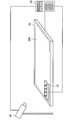
- the information processing system includes a server 10, a display device 20, a tool 22, and a projector 24.
- the server 10 is an example of an information processing device according to the present disclosure.
- the server 10 is a device for controlling operations of the display device 20 and the projector 24 described later.
- the server 10 can transmit / receive information to / from the display device 20, the tool 22, and the projector 24 by wired communication or wireless communication.
- the display device 20 is a device having a display unit 200 that displays a display screen.
- the display device 20 may be, for example, a table plate type device as shown in FIG.
- a monitor such as a monitor for a desktop PC (Personal Computer) may be a device in which the display is oriented in the horizontal direction, or a rear projection type display that projects with a built-in projector from the back of the screen. Good.
- the display device 20 is mainly described as an example of a table plate type device.
- the display device 20 displays image information received from the server 10 on the display unit 200, for example.
- the image information is, for example, information on the screen of the application.
- the display unit 200 is basically composed of a large light emitting display such as an LCD (Liquid Crystal Display) or an OLED (Organic Light Emitting Diode).
- the display unit 200 can also have a touch panel.
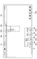
- FIG. 2 is an explanatory diagram showing a display example (application screen 30) of the application screen displayed on the display unit 200.
- the application screen 30 includes a GUI such as a drop-down menu 300, a ribbon 302, a dial 304, and a button 306.
- the GUI is an example of an operation image in the present disclosure.
- the GUI is an image for the user to operate a function corresponding to the GUI, for example.
- the user can cause the server 10 to execute a desired process, for example, by selecting one of a plurality of GUIs displayed on the application screen 30 and operating the selected GUI.
- the application screen 30 may include only one type of GUI or may include a plurality of types of GUI. In the following description, the application screen 30 will be described with a focus on an example including a plurality of types of GUIs.
- the projector 24 is an example of a projection unit in the present disclosure.
- the projector 24 is a device that projects image information by light emission.
- the projector 24 projects image information received from the server 10.
- the projector 24 changes the direction of projection according to the control signal received from the server 10.
- the projector 24 may be configured such that the user can manually change the position and the projection direction.
- 1 illustrates an example in which only one projector 24 is installed.
- the present invention is not limited to this example, and a plurality of projectors may be installed. It is also possible to project so that one content is displayed by projection from a plurality of projectors 24.
- the tool 22 is an example of an operation unit in the present disclosure.
- the tool 22 is a device for the user to input to the application.
- the tool 22 is basically a device having a size and weight that can be carried by a user by hand. Further, as will be described later, the tool 22 may be configured in various shapes.
- the tool 22 can transmit user operation information on the tool 22 to the server 10 by performing wired communication or wireless communication with the server 10, for example.
- the tool 22 may have a display on the surface, and image information may be displayed on the display.
- FIG. 3 is an explanatory view showing the appearance of the tool 22-1 which is an example of the shape of the tool 22.
- the tool 22-1 has a stick 222 for the user to operate.
- the tool 22-1 may have a shape having only one operation system like the tool 22-1a shown in the left diagram of FIG.
- a shape in which a plurality of operation systems 220 such as four, for example, are integrated may be used like a tool 22-1c shown in the right diagram of FIG.
- the user can operate the stick 222 by the operation method as shown in FIG.
- the stick 222 of the tool 22-1 may be rotated counterclockwise by the user and / or may be rotated clockwise.
- an operation of tilting the stick 222 in eight directions that are oblique to the front, back, left, and right may be possible.
- an operation of pushing the stick 222 downward may be possible.
- the user may be able to perform an operation of pinching and pulling up the stick 222.
- the detection of rotation, depression, or depression of the stick 222 shown in FIG. 4 may be detectable by, for example, an electronic device included in the tool 22-1.
- the detection of the operation of the stick 222 is performed by using the pressure at the time of the operation on the tool 22-1. It may be performed by the display unit 200 detecting.
- the display unit 200 has a touch panel, the display device 20 automatically recognizes the position of the tool 22 arranged on the display unit 200 and touches the display area where the tool 22 is arranged. The sensor may be disabled. This makes it possible to prevent touch malfunctions.
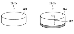
- FIG. 5 is an explanatory view showing an example of the appearance of the tool 22-2 (tool 22-2a and tool 22-2b) which is an example of another shape of the tool 22.
- This tool 22-2 has an invisible marker 224 on the surface of the tool 22-2, for example.
- the invisible marker 224 is a marker that can be engineeringly read based on, for example, an image taken by an infrared camera and cannot be visually recognized by the user. Although details will be described later, the tool 22-2 can recognize the user's operation content on the tool 22-2 based on the detection result of the operation of the invisible marker 224 such as rotation.
- the tool 22-2 may have a single-stage configuration like the tool 22-2a shown in the left figure of FIG. 5, or may be two-stage like the tool 22-2b shown in the right figure of FIG. It may be a configuration. Further, this tool 22-2b may have a stick 222 inside as shown in FIG. Then, when the user presses the tool 22-2b from above, the stick 222 may be pressed to give the user a click feeling. In addition, the tool 22-2b may be mounted so that, for example, when the user rotates the tool 22-2b by hand, a weight at the time of rotation is given to the user.
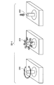
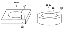
- FIG. 6 is an explanatory view showing another example of the shape of the tool 22-2 (the tool 22-2c and the tool 22-2d).
- the tool 22-2c and the tool 22-2d have a dial part 226 for the user to perform a rotation operation and a determination operation, and the dial part 226 and the invisible marker 224 are separated from each other. Be placed.
- the user With the tool 22-2c and the tool 22-2d, the user basically operates only the dial unit 226. For this reason, it is possible to avoid the invisible marker 224 being blocked (hidden) by the user's hand.
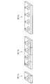
- FIGS. 7 and 8 are explanatory diagrams showing still another example of the shape of the tool 22-2 (tool 22-2e).
- FIG. 7 is an explanatory diagram showing the appearance of the front surface of the tool 22-2e
- FIG. 8 is an explanatory diagram showing the appearance of the back surface of the tool 22-2e.
- the tool 22-2e has a shape in which a plurality of operation systems 220 having the same shape as the tool 22-2c shown in FIG.
- the tool 22-2e has a conductor 228 on the back of each dial part 226.
- the display unit 200 includes a touch panel
- the tool 22-2e is disposed on the display unit 200, and the dial unit 226 is pressed by the user, for example, the display device 20 is connected via the conductor 228. It is possible to recognize that the dial unit 226 has been pressed.
- the tool 22-2e may have a plurality of protrusions 2240 such as three points at positions corresponding to the individual invisible markers 224 on the back surface of the tool 22-2e.
- the tool 22-2e is arranged on the display unit 200, and any one of the dial units 226 is rotated by the user, for example, display is performed.
- the device 20 can recognize that the invisible marker 224 corresponding to the dial unit 226 is rotating (even if the invisible marker 224 is not detected).
- anti-slip 230 may be provided at, for example, the four corners of the back surface of the tool 22-2e.
- the tools 22-2a to 22-2d shown in FIGS. 5 and 6 can also have the conductor 228, the plurality of protrusions 2240, and the anti-slip 230, similarly to the tool 22-2e.
- the tool 22-1 shown in FIG. 3 can also have the conductor 228 and the anti-slip 230.
- the tool 22-2 may have a marker (hereinafter referred to as a visible marker) that can be visually recognized by a human instead of the invisible marker 224. And this visible marker can be read based on the image image
- a visible marker hereinafter referred to as a visible marker
- the tool 22 has been described above. In the following description, the tool 22-1 and the tool 22-2 shown in FIGS. 3 to 8 are simply referred to as the tool 22 when it is not necessary to distinguish between them.
- FIG. 1 shows an example in which the projector 24 projects an image on the display unit 200 (or the tool 22), but the present invention is not limited to such an example.
- the projector 24 can project an image on a desk (not shown) on which the projector 24 is disposed, for example.
- the tool 22 is placed on the desk.
- the display device 20 may be a desktop monitor arranged on the desk.
- the information processing system may further include one or more cameras.
- the server 10 uses a camera image recognition (depth sensing) technique between a projection surface or a projection target object projected by the projector 24 and an operation body (for example, a finger, a stylus, etc.). It is also possible to detect the distance. Then, based on the detection result of the distance, the user's touch interaction with the GUI projected by the projector 24 may be enabled.
- a camera image recognition depth sensing
- GUIs In many application screens, a plurality of types of GUIs are usually arranged as in the application screen 30 shown in FIG. 2, and the individual GUIs are arranged in various locations on the screen. There are many cases. For example, in the example shown in FIG. 2, the drop-down menu 300 is arranged at the upper left in the application screen 30, and the button 306 is arranged at the lower right. In order to operate these GUIs with a mouse, the user must move the mouse pointer between the upper left and lower right on the application screen 30. In addition, the user must move the line of sight largely in order to confirm the position of the mouse pointer displayed on the application screen 30.
- the display has a touch panel
- the user has to move his / her hand greatly, which is troublesome for operation. As the display is larger, the distance to move the finger (and arm) and line of sight increases, and the time required for the operation becomes longer.
- the server 10 according to the present embodiment has been created with the above circumstances in mind.
- the server 10 according to the present embodiment associates a plurality of GUI functions with one tool 22 to allow the user to perform a desired operation collectively at hand. Further, the server 10 can display the correspondence relationship between the GUI and the tool 22 in an easy-to-understand manner for the user.
- GUI GUI
- the server 10 can display the correspondence relationship between the GUI and the tool 22 in an easy-to-understand manner for the user.
- FIG. 9 is a functional block diagram showing the configuration of the server 10 according to the present embodiment.
- the server 10 includes a control unit 100, a communication unit 120, and a storage unit 122.
- the control unit 100 generally controls the operation of the server 10 using hardware such as a CPU (Central Processing Unit) 150 and a RAM (Random Access Memory) 154, which will be described later, built in the server 10. Further, as illustrated in FIG. 9, the control unit 100 includes an association unit 102, a display control unit 104, a function control unit 110, a tool control unit 112, a marker detection unit 114, a warning unit 116, and a data management unit 118.
- the display control unit 104 includes a tool display control unit 106 and a screen display control unit 108.
- the associating unit 102 associates the GUI selected by the user with the tool 22 based on a predetermined operation on the tool 22 and selection by the user of the GUI displayed on the display screen. For example, the association unit 102 is selected when any of a plurality of GUIs displayed on the display screen is selected by the user while the user performs a predetermined operation on the tool 22. The made GUI is associated with the tool 22.
- FIG. 10 shows an example in which the application screen 30 shown in FIG. 2 is displayed on the display unit 200 and the tool 22 is arranged on the display unit 200 (for example, the lower left position in FIG. 10) by the user. Is shown.
- the tool 22 has a shape in which a plurality of operation systems 220 such as four are combined.
- the user desires to associate a specific button 3020b included in the ribbon 302 with the operation system 220d.
- the determination mechanism of the operation system 220d is operated by the user, and the application screen is displayed while the operation is being performed.
- the associating unit 102 associates the button 3020b with the operation system 220d.
- the user can subsequently operate the function corresponding to the button 3020b with the operation system 220d.
- the determination mechanism of the tool 22 may be to quickly rotate the stick 222 left and right as shown in the left diagram of FIG.
- the stick 222 as shown in the right figure of FIG.
- the association unit 102 associates the button 3020b with the operation system 220d based on the user's operation while the mapping mode of the application is activated. For example, when a plurality of GUIs displayed on the application screen are sequentially selected by the user during the activation of the mapping mode, for example, the associating unit 102 selects the GUIs selected in sequence and the respective operation systems. 220 are associated with each other.
- examples of how to select a GUI on the application screen 30 include that the user touches the displayed GUI with a finger or a stylus, or that the user clicks the mouse (after moving the mouse pointer to the GUI position). It is.
- Tool display control unit 106 (2-1-3-1. Tool display control example 1)
- the tool display control unit 106 is an example of a display control unit in the present disclosure.
- the association unit 102 associates the GUI and the tool 22, the tool display control unit 106 displays a display indicating the correspondence between the GUI and the tool 22 at a position related to the tool 22.
- the tool display control unit 106 causes the projector 24 to project a display indicating the correspondence between the GUI and the tool 22 at a position related to the tool 22.
- the tool display control unit 106 displays a display indicating the correspondence on the tool 22 (a display included in the tool 22).
- the position related to the tool 22 may be, for example, near the top of the tool 22 or in the vicinity of the side, or may be on the surface of the tool 22.
- the display indicating the correspondence relationship between the GUI and the tool 22 may include a part of the GUI image associated with the tool 22.
- FIG. 11 is an explanatory view showing a projection example of a display showing a correspondence relationship between the GUI and the tool 22 after the operation shown in FIG. 10 is performed.
- the tool display control unit 106 projects a mapping GUI display 40 indicating the association between the button 3020 b and the operation system 220 d on the projector 24 on the display screen above the operation system 220 d.
- the mapping GUI display 40 may be, for example, an image obtained by cutting out an image of an area including the button 3020b on the display screen as shown in FIG.
- the mapping GUI display 40 may be an image in which the shape or size of the image of the button 3020b is arbitrarily changed.
- the visibility of the mapping GUI display 40 can be improved by enlarging and projecting the image of the button 3020b.
- FIG. 12 is an explanatory diagram showing an example of projection when all the operation systems 220 included in the tool 22 are associated with the GUI on the application screen 30 shown in FIG.
- the tool display control unit 106 arranges the operation system 220a on the display unit 200 as illustrated in FIG.
- a mapping GUI display 40a indicating the correspondence between the drop-down menu 300 and the operation system 220a is projected on the projector 24.
- the tool display control unit 106 causes the projector 24 to project a mapping GUI display 40b indicating the correspondence between the dial 3040a and the operation system 220b on the display unit 200 above the position where the operation system 220b is arranged.
- the position where the mapping GUI display 40 is projected may be fixed.
- the position at which the mapping GUI display 40 is projected may be freely changed by the user according to, for example, a user input to the application or a user operation on the corresponding operation system 220.
- the shape and size of the projected mapping GUI display 40 may be freely set or changed by the user.
- the shape and size of the mapping GUI display 40 may be set in advance.
- the tool display control unit 106 may project the mapping GUI display 40 on the projector 24 darkly while the user is not operating. Furthermore, the tool display control unit 106 may make the mapping GUI display 40 brighter and project it on the projector 24 when the user resumes the operation.
- Tool display control example 2 (2-1-3-2. Tool display control example 2) Further, when the GUI and the tool 22 are associated with each other by the association unit 102, the tool display control unit 106 has the same color as the color of a line displayed around the GUI, for example, by the screen display control unit 108 described later. Can be projected on the projector 24 at a position related to the tool 22, or can be displayed on the tool 22.
- FIG. 13 is an explanatory diagram showing another display example when all the operation systems 220 included in the tool 22 are associated with the GUI on the application screen 30 shown in FIG. 11.
- the tool display control unit 106 displays the mapping relationship display 42a having the same color as the color of the line 44a displayed around the drop-down menu 300 (corresponding to the operation system 220a). Is projected onto the surface of the operation system 220a by the projector 24, or the operation system 220a is caused to emit light.
- the tool display control unit 106 projects the mapping relationship display 42b having the same color as the color of the line 44b displayed around the dial 3040a (associated with the operation system 220b) onto the surface of the operation system 220b. Or displayed on the operation system 220b. The same applies to the operation system 220c and the operation system 220d.
- the tool display control unit 106 displays a mapping GUI display 40 corresponding to the GUI image after the change every time the GUI image associated with the tool 22 is changed by the screen display control unit 108 described later. 24 can be projected.
- the tool display control unit 106 performs an aspect in accordance with the adjusted parameter value every time the parameter value related to the GUI function associated with the tool 22 is adjusted by the function control unit 110 described later. It is also possible to project the mapping GUI display 40 on the projector 24. For example, every time the value of the parameter is adjusted, the tool display control unit 106 changes the parameter value included in the mapping GUI display 40 to the adjusted value, and the changed mapping GUI display 40. Is projected on the projector 24.
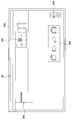
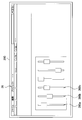
- FIG. 14 is an explanatory diagram showing an example in which another application screen (application screen 32) is displayed on the display unit 200.
- This application screen 32 is, for example, a music-related application screen.
- the application screen 32 has a window 322 including a plurality of dials 320.
- the dial 320 is a GUI for the user to adjust the value of a parameter previously associated with the dial 320 such as “volume”.
- dial 320 includes a display area for parameter values associated with dial 320.
- the dial 320b named “VOLUME” displays “10” as the value of the parameter associated with the dial 320b.
- FIG. 14 shows an example in which the tool 22 is arranged at a position that partially overlaps the display area of the window 322 in the display unit 200.
- the tool display control unit 106 causes the projector 24 to project an image 46a of the dial 320a associated with the operation system 220a on the surface of the operation system 220a.
- the tool display control unit 106 causes the projector 24 to project the image 46a of the dial 320a on the invisible marker 224 of the operation system 220a.
- the image 46 a of the dial 320 a includes parameter values related to the function of the dial 320 a (“1.0” in the example shown in FIG. 14).
- the tool display control unit 106 causes the projector 24 to project the image 46b of the dial 320b (named “VOLUME”) associated with the operation system 220b on the surface of the operation system 220b.
- the image 46b of the dial 320b includes parameter values related to the function of the dial 320b (“10” in the example shown in FIG. 14). The same applies to the operation system 220c and the operation system 220d.
- the tool display control unit 106 further displays an image (a window in the example shown in FIG. 14) displayed under the tool 22 arranged on the display unit 200. It is also possible to cause the projector 24 to project an image of an overlapping area between the 322 and the tool 22 on the surface of the tool 22. According to such a configuration, it is possible to realize an effect that the user perceives as if the tool 22 is transparent. In particular, when the color of the surface of the tool 22 is, for example, a white base color, the projected image looks more beautiful, so that the user can perceive as if it is more transparent.
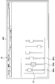
- FIG. 15 is an explanatory diagram showing an example in which another application screen (application screen 34) is displayed on the display unit 200.
- the application screen 34 includes a plurality of GUIs 340 such as a toolbar and a drop-down menu.
- each operation system 220 included in the tool 22 is associated with each GUI 340 displayed on the application screen 34 by the association unit 102.
- the tool display control unit 106 causes the projector 24 to project a partial image 48b of the drop-down menu 340b associated with the operation system 220b onto the surface of the operation system 220b.
- the image 48 b is, for example, a selection candidate where the current cursor is located among a plurality of selection candidates displayed in the drop-down menu 340 b (“1 /” in the example shown in FIG. 15.
- a predetermined number of selection candidate image regions including 8 ”) may be cut out.
- the tool display control unit 106 determines the position of the cursor in the drop-down menu 340b. And the image 48b after the movement of the cursor can be projected on the projector 24 onto the surface of the operation system 220b. If a determination operation such as pressing the stick 222 or the dial unit 226 included in the operation system 220b is detected after the projection, the server 10 selects a plurality of selections displayed in the drop-down menu 340b. It is possible to determine that the selection candidate where the cursor is currently located has been selected by the user.
- -Modification As a modification, for example, when a toolbar is associated with the operation system 220 and the user does not operate the operation system 220, a user operation on the operation system 220 is newly detected. At this time, the tool display control unit 106 displays all or part of the image newly displayed on the application screen 34 when the toolbar associated with the operation system 220 is selected. You may make it project on the projector 24 upwards. For example, in the example shown in FIG. 15, when a user operation on the dial unit 226 included in the operation system 220a is detected, the tool display control unit 106 displays the toolbar 340a associated with the operation system 220a. An image newly displayed on the application screen 34 when selected may be projected on the projector 24 on the surface of the operation system 220a (instead of the image 48a).
- the screen display control unit 108 to be described later can simultaneously display on the application screen 34 an image that is newly displayed when the toolbar is selected.
- the screen display control unit 108 is an example of a display control unit in the present disclosure.
- the screen display control unit 108 causes the display unit 200 to display a display screen including one or more GUIs such as the application screen 30 illustrated in FIG.
- the screen display control unit 108 further displays a display indicating the correspondence between the GUI and the tool 22. It is possible to display at a position related to the GUI on the screen.
- the screen display control unit 108 causes the display unit 200 to display a line 44 of a predetermined color around the GUI associated with the tool 22 as shown in FIG. More specifically, the screen display control unit 108, for example, every time each operation system 220 included in the tool 22 is associated with a GUI, the screen display control unit 108 has a color different from the color of the line 44 of the already associated GUI. The line 44 is displayed on the display unit 200 around the newly associated GUI.
- the screen display control unit 108 causes the display unit 200 to emit light in the vicinity of the arrangement region of the tool 22 on the display unit 200 in the same color as the color of the line displayed around the GUI associated with the tool 22. You may let them.
- the screen display control unit 108 changes the GUI image displayed on the display screen based on the user's operation mode with respect to the tool 22 when the GUI and the tool 22 are associated by the association unit 102. It is possible to make it.
- the screen display control unit 108 may display an image of the dial 3040b so that the dial 3040b continues to rotate with inertia on the display screen.
- the operation system 220b associated with the drop-down menu 340b has a stick 222 like the tool 22-1a shown in FIG. 3, and the operation system 220b has a stick.
- the screen display control unit 108 may display the cursor position in the drop-down menu 340b by moving it at a higher speed.
- the predetermined operation with respect to the stick 222 include an operation of pressing the stick 222 deeper downward, or an operation of tilting the stick 222 forward or backward with a strong force. According to such a configuration, it can be expected that the operation efficiency of the user is increased.
- the function control unit 110 controls a function corresponding to the GUI associated with the tool 22 based on a user operation on the tool 22. For example, the function control unit 110 adjusts the value of the parameter related to the GUI associated with the tool 22 based on the user's operation on the tool 22. For example, in the example shown in FIG. 14, when the dial part 226 of the operation system 220b is rotated clockwise by the user, the function of the dial 320b named “VOLUME” associated with the operation system 220b is used. Increase the value of the relevant parameter (eg “volume”).
- the tool control unit 112 controls the operation of the tool 22 with which the server 10 can communicate, for example.
- the tool control unit 112 operates the tool 22 so that physical feedback is given to the user at a predetermined timing.
- the clock GUI and the tool 22 are associated with each other and the user rotates the tool 22, for example, the tool control unit 112 sets the time indicated by the clock GUI to “12:00”, for example.
- the tool 22 is operated so as to give the user a feeling of clicking lightly.
- the user rotates the tool 22 associated with a certain GUI and the value of the parameter related to the GUI function reaches the maximum value or the minimum value, the user feels that the rotation becomes heavy.
- the tool 22 may be actuated to give or the rotation may be stopped. According to such a configuration, the user can perform a desired operation with little viewing of the GUI on the display screen.
- the tool control unit 112 may change the weight when the tool 22 is rotated according to the type of GUI associated with the tool 22. This makes it possible to give the user a texture similar to a real dial when the tool 22 is rotated.
- the tool control unit 112 gives a click feeling to the user every time the value of the parameter related to the GUI function associated with the tool 22 reaches a predetermined value, for example. It is also possible to operate the tool 22 as described above. According to such a configuration, it is possible to synchronize the change in value and the click feeling given to the user.
- the tool control unit 112 may vibrate the tool 22 every time the selected button among a plurality of buttons included in the ribbon is switched or the position of the cursor in the drop-down menu moves.
- the tool control unit 112 may vibrate the tool 22 when a determination operation using the tool 22 by the user is detected. According to these configurations, when operating the tool 22 associated with the GUI, the user can perform a desired operation even if the number of times of directing the line of sight to the GUI is reduced. And the improvement of operation efficiency can be expected.
- the marker detection unit 114 recognizes the invisible marker 224 from the tool 22 based on, for example, an image captured by the tool 22 using an infrared camera.
- the marker detection unit 114 recognizes the operation content of the user based on the detection result of the movement of the invisible marker 224. For example, when it is detected that the invisible marker 224 is rotating, the marker detection unit 114 recognizes that the user is performing a rotation operation on the tool 22.
- Warning unit 116 notifies the user of a warning when a user operation on the tool 22 is detected and the invisible marker 224 is not detected by the marker detection unit 114.
- the warning unit 116 causes the display unit 200 to display an error display notifying that the operation error of the tool 22 (invisible marker detection error) is caused, or causing the projector 24 to project the error display.
- the warning unit 116 causes the projector 24 to project the error display in the vicinity of the tool 22 having the corresponding invisible marker 224.
- the warning unit 116 may vibrate the tool 22 with a predetermined vibration pattern, or may output a buzzer to a speaker (not shown) that can communicate with the server 10.
- the detection method that the user is operating the tool 22 is, for example, that the tool 22 detects that the user's hand is in contact with the tool 22.
- the data management unit 118 associates mapping information indicating the result of association by the association unit with the application screen displayed on the display unit 200 and stores the mapping information in the mapping information DB 124 described later.
- the mapping information is, for example, information indicating a correspondence relationship between each operation system 220 included in the tool 22 and a GUI included in the application screen.
- mapping information DB 1234 is a database in which mapping information and an application screen displayed when mapping information is generated are registered in association with each other.
- mapping information DB 124 a user ID, an operation date and time, and the like may be registered in association with each other.
- the communication unit 120 transmits and receives information to and from other devices that can communicate with the server 10. For example, the communication unit 120 transmits the screen information of the application screen to the display device 20 according to the control of the screen display control unit 108. In addition, the communication unit 120 transmits image information indicating a correspondence relationship between the GUI and the tool 22 to the projector 24 under the control of the tool display control unit 106. In addition, the communication unit 120 receives a detection result of a user operation on the tool 22 from the tool 22.
- the storage unit 122 can store various data such as the mapping information DB 124 and software, for example.
- the configuration of the server 10 according to the present embodiment is not limited to the configuration described above.
- the mapping information DB 124 can be stored in another device (not shown) that can communicate with the server 10.
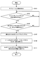
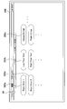
- FIG. 16 is a flowchart showing the operation according to the present embodiment. As shown in FIG. 16, first, the screen display control unit 108 of the server 10 displays an application screen on the display unit 200 (S101).
- the associating unit 102 waits until a detection result indicating that the determination mechanism of the tool 22 is operated by the user is received from the tool 22 (S103).
- the determination mechanism of the tool 22 is operated by the user (S103: Yes)
- the associating unit 102 determines that the tool 22 is in the mapping setting state.
- the associating unit 102 determines whether any of the GUIs displayed on the application screen is selected by a user's touch or a mouse click while the determination mechanism of the tool 22 is operated by the user. Is determined (S105). If the user's operation for the determination mechanism of the tool 22 is canceled before any GUI is selected (S105: No), the server 10 cancels the mapping setting state of the tool 22, and performs the operation of S103 again. Do.
- the associating unit 102 maps the selected GUI to the tool 22 (S107).
- the tool display control unit 106 causes the projector 24 to project a part of the GUI image mapped in S107 on the surface of the tool 22 or in the vicinity of the tool 22 (S109).
- the screen display control unit 108 displays, for example, a predetermined color line indicating the mapping relationship between the GUI mapped in S107 and the tool 22 on the display unit 200 around the GUI on the application screen (S111). .
- the association unit 102 22 may be shifted to a mode for re-mapping (that is, the mapping setting state). Further, when the GUI is mapped in advance to the tool 22 and the stick 222 of the tool 22 is pressed by the user for a short time, the server 10 performs a determination operation on the GUI currently mapped to the tool 22. You may recognize that it was performed by the user.
- the tool display control unit 106 irradiates the projector 24 so that the stick 222 (or the entire tool 22) of the tool 22 blinks, or the tool 22 emits light by itself. You may let them. According to this display example, the user can easily understand whether or not the tool 22 is in the mapping setting state.
- the server 10 displays, for each operation system 220, a correspondence relationship between the GUI and the operation system 220. Is projected on the surface of the operation system 220 or in the vicinity of the operation system 220 or displayed on the operation system 220. Therefore, the user can understand at a glance which GUI is associated with which operation system 220.
- a plurality of GUI images associated with one tool 22 can be displayed on the tool 22 or in the vicinity of the tool 22, so that the movement distance of the user's line of sight for operating the GUI can be reduced. Can be made.
- the operation efficiency can be further improved by sharing the work with the left and right hands.
- the user can perform the touch operation with the right hand or the operation using the mouse or the stylus at the same time while always placing the left hand on the tool 22 and performing the operation.
- FIG. 17 is an explanatory view showing a scene in which the tool 22-2 is arranged on the GUI display area displayed on the display unit 200 by the user.
- the associating unit 102 Associate tool 22-2.
- the type of the tool 22 used in this application example is basically the tool 22-2, that is, the tool 22 having the invisible marker 224. Furthermore, in this application example, basically, a tool 22-2 having only one operation system 220 such as the tool 22-2a shown in FIG. 5 is used.
- association unit 102 automatically cancels the association between the GUI and the tool 22 when the tool 22 is removed from the display unit 200 after the GUI and the tool 22 are associated with each other. .
- the association unit 102 may maintain the association between the GUI and the tool 22 until a predetermined time elapses after the tool 22 is removed from the display unit 200.
- Tool display control unit 106 When the association unit 102 associates the GUI with the tool 22, the tool display control unit 106 according to this application example displays a GUI image associated with the tool 22 on the surface of the tool 22. For example, in the above case, the tool display control unit 106 causes the projector 24 to project the GUI image on the surface of the tool 22 or display the GUI image on the tool 22 (a display included in the tool 22).
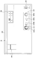
- FIG. 18 is an explanatory diagram showing an example of projection when the application screen 30 shown in FIG. 2 is displayed on the display unit 200 and the tool 22-2 is arranged on the display unit 200 by the user. .
- the tool 22 is arranged on the display area of the dial 3040 a in the display unit 200 and the dial 3040 a and the tool 22 are associated with each other by the association unit 102.
- the tool display control unit 106 causes the projector 24 to project the image of the dial 3040a onto the surface of the tool 22-2.
- the surface of the tool 22-2 is not usually covered with a hand.
- the tool 22-2 is operated as follows. For this reason, it is possible to indirectly prevent the invisible marker 22-2 from being covered with the user's hand, and it is possible to greatly reduce the invisible marker 22-2 from becoming unreadable.
- the tool display control unit 106 when a GUI image is projected on the surface of the tool 22 and the surface of the tool 22 is detected by the user to be pinched or hit with a finger, the tool display control unit 106 The GUI image associated with the tool 22 can be enlarged or reduced and projected onto the surface of the tool 22 or displayed on the tool 22.
- Screen display control unit 108 (3-1-3-1. Screen display example 1)
- the screen display control unit 108 causes the display unit 200 to emit light around the area where the tool 22 is arranged in the display unit 200. To display brightly.
- FIG. 19 shows a state where the tool 22-2 is arranged on the display area of the dial 3040a in the display unit 200, as in FIG.
- the screen display control unit 108 causes the display unit 200 to brightly display, for example, by emitting light around the arrangement area of the tool 22-2. According to this configuration, it is possible to notify the user that the association between the GUI and the tool 22-2 has been completed. Therefore, it is not necessary for the user to operate the tool 22-2 in order to confirm whether or not the association is completed.
- the screen display control unit 108 may use the tool when the tool 22 is translated on the display unit 200 after the GUI and the tool 22 are associated by the association unit 102. It is also possible to move the display position of the window including the GUI associated with the object 22 by following the movement of the tool 22.
- the screen display control unit 108 follows the movement of the tool 22-2 and moves the display position of the window 322 by the same movement direction and the same movement distance as the tool 22-2 for display.
- the user can move the window including the GUI associated with the tool 22 closer to the user by translating the tool 22 closer to the user on the display unit 200. .
- the user can operate the GUI at hand or view a window including the GUI, which makes the operation easier.
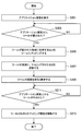
- S201 shown in FIG. 20 is the same as that of S101 according to the present embodiment.
- the associating unit 102 waits until a detection result indicating that the tool 22-2 is arranged on the display unit 200 is received from the display device 20, for example (S203).
- the associating unit 102 displays the GUI displayed in the display area in which the tool 22-2 is arranged on the tool 22-2. 2 is mapped (S205).
- the tool display control unit 106 causes the projector 24 to project the GUI image mapped in S205 onto the surface of the tool 22-2 (S207).
- the screen display control unit 108 causes the display unit 200 to display brightly by, for example, emitting light around the arrangement area of the tool 22 (S209).
- the associating unit 102 waits until the tool 22-2 is removed from the display unit 200 (S211).
- the associating unit 102 cancels the association between the corresponding GUI and the tool 22 (S213).
- the server 10 As described above, for example, with reference to FIG. 20 and the like, the server 10 according to this application example is displayed on the display area where the tool 22 is arranged when the tool 22 is arranged on the display unit 200 by the user. The associated GUI and the tool 22 are automatically associated with each other. Then, the server 10 projects or displays the GUI image associated with the tool 22 on the surface of the tool 22.
- the user can operate the GUI more intuitively and efficiently while looking at the GUI displayed on the surface of the tool 22.
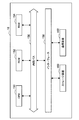
- FIG. 21 is an explanatory diagram showing a display example of an application screen (application screen 36) according to this application example.
- the application screen 36 includes a plurality of slider GUIs 360.
- the slider GUI 360 is a GUI that allows a user to move a knob included in the slider GUI 360 in the vertical direction, for example, to increase or decrease a parameter value of a function corresponding to the slider GUI 360.
- association unit 102 For example, as illustrated in FIG. 22, the association unit 102 according to this application example is an area in which the tool 22 is arranged when the user places the tool 22 on the display area of the knob of the slider GUI 360 in the display unit 200. Are associated with the slider GUI 360 displayed in FIG.
- the user can move the knob of the slider GUI 360 by moving the tool 22 on the display unit 200. For this reason, the user can operate the slider GUI 360 more intuitively.
- the slider GUI 360 that is not yet associated with the tool 22 among the slider GUI 360 on the application screen 36 can be automatically set so as not to accept a mouse operation or a touch operation, for example.
- the user can operate the slider GUI 360 only by using the tool 22 in principle, so that the user can concentrate on the operation of the tool 22. Further, since the user operates only the tool 22 without using a plurality of operation methods, it can be expected that the operation error of the user is reduced.
- the shape of the tool 22 employed in this application example may be the same as or similar to the knob of the slider GUI 360 as shown in FIG. By adopting such a shape, the user can operate the slider GUI 360 on the display unit 200 as if operating a real slider.
- the server 10 includes a CPU 150, a ROM (Read Only Memory) 152, a RAM 154, an internal bus 156, an interface 158, a storage device 160, and a communication device 162.
- the CPU 150 functions as an arithmetic processing device and a control device, and controls the overall operation in the server 10 according to various programs. Further, the CPU 150 realizes the function of the control unit 100 in the server 10.
- the CPU 150 is configured by a processor such as a microprocessor.
- the ROM 152 stores programs used by the CPU 150, control data such as calculation parameters, and the like.
- the RAM 154 temporarily stores a program executed by the CPU 150, for example.
- the internal bus 156 is composed of a CPU bus and the like.
- the internal bus 156 connects the CPU 150, the ROM 152, and the RAM 154 to each other.
- the interface 158 connects the storage device 160 and the communication device 162 to the internal bus 156.
- the storage device 160 exchanges data with the CPU 150 via the interface 158 and the internal bus 156.
- the storage device 160 is a data storage device that functions as the storage unit 122.
- the storage device 160 includes, for example, a storage medium, a recording device that records data on the storage medium, a reading device that reads data from the storage medium, or a deletion device that deletes data recorded on the storage medium.
- the communication device 162 is a communication interface including a communication device for connecting to a communication network such as a public network or the Internet.
- the communication device 162 may be a wireless LAN compatible communication device, an LTE (Long Term Evolution) compatible communication device, or a wire communication device that performs wired communication. This communication device 162 functions as the communication unit 120.
- timbre assignment information can be associated with a keyboard of a music keyboard.
- the user can easily operate the keyboard while viewing the timbre assignment information associated with the keyboard.
- FIG. 24 is an explanatory diagram showing a display example of a tone color assignment screen display example (tone color assignment screen 38) according to the first modification.
- FIG. 25 is an explanatory diagram showing an example of a music keyboard (music keyboard 60).
- the components included in the server 10 according to the first modification are the same as those in the present embodiment. Below, only the component which has a function different from embodiment mentioned above is demonstrated.
- any one of a plurality of tone color selection buttons displayed on the tone color assignment screen is selected by the user while any key included in the music keyboard is pressed by the user. If selected, the keyboard pressed by the user is associated with the timbre assignment information corresponding to the timbre selection button selected by the user.
- the associating unit 102 When the timbre selection button 380a on the timbre assignment screen 38 is selected by the user while the keyboard 600a is pressed by the user, the associating unit 102 The keyboard 600a is associated with timbre assignment information corresponding to the timbre selection button 380a (that is, “Bass Drum 1”).
- the timbre assignment screen 38 may include a selection button 382 for selecting a set (combination) of a plurality of sound sources such as “drum set”.
- the selection button 382 is selected by the user while the keyboard 600a is pressed by the user, for example, the associating unit 102 selects a plurality of tone assignment information (for example, “ Bass Drum ”,“ Snare Drum ”,“ Open Hi-Hat ”,“ Closed Hi-Hat ”, etc.) may be automatically associated with the individual keyboard 600 in the music keyboard 60.
- the associating unit 102 has a plurality of buttons corresponding to the selection button 382 only when the selection button 382 is selected by the user on the timbre assignment screen 38 (that is, even when the keyboard 600 is not operated at all by the user). May be automatically associated with each keyboard 600 in the music keyboard 60.
- the tool display control unit 106 When the association unit 102 associates the keyboard with the timbre assignment information, the tool display control unit 106 according to the first modified example displays the timbre assignment information associated with the keyboard on or near the surface of the keyboard. The image is projected on the projector 24. For example, as shown in FIG. 25, the tool display control unit 106 causes the projector 24 to project a character string “Bass Drum 1”, which is timbre assignment information associated with the keyboard 600a, onto the surface of the keyboard 600a. When the keyboard 600 has a display, the tool display control unit 106 may display timbre assignment information associated with the keyboard 600 on the keyboard 600 itself.
- the tool display control unit 106 can also cause the projector 24 to project the numerical value of the performance information associated with the keyboard 600 onto or near the surface of the keyboard 600.
- the server 10 according to the modified example 1 projects the timbre assignment information associated with the keyboard onto or near the keyboard. For this reason, the user can operate the keyboard while viewing the associated tone color assignment information. And operation efficiency can be improved.
- the user can easily confirm the performance information associated with the keyboard by looking at the keyboard. The user can feed back the confirmation result to the performance in real time.
- the information processing apparatus may be a mobile phone such as a PC or a smartphone, or a game machine.
- the information processing apparatus may be an apparatus in which the function of the server 10 and the display device 20 described above are integrally configured.
- the information processing device may be the display device 20.
- the server 10 may not be provided.
- a first display control for displaying an operation image on a display screen;
- a display control unit that executes a second display control for displaying a first display indicating a correspondence relationship between the operation image and the operation unit at a position related to the operation unit;
- An information processing apparatus comprising: (2) The information processing apparatus according to (1), wherein the display control unit causes the projection unit to project the first display at a position related to the operation unit.
- the information processing apparatus further includes a function control unit that adjusts a parameter value related to the function of the operation image associated with the operation unit based on a user operation on the operation unit.
- the information processing apparatus according to 3).
- the display control unit displays the first display in a mode corresponding to the adjusted parameter value every time the parameter value is adjusted by the function control unit.
- Processing equipment (6)
- the display control unit further displays a second display indicating a correspondence relationship between the operation image and the operation unit at a position related to the operation image on the display screen.
- the information processing apparatus according to any one of (1) to (7), wherein a position related to the operation unit is a surface of the operation unit.
- a marker is installed on the surface of the operation unit, The information processing apparatus according to (8), wherein a user operation content is recognized based on a detection result of the marker movement.
- the information processing apparatus further includes a marker detection unit that detects the marker from the operation unit; The information processing apparatus according to (9), further including a warning unit that notifies the user of a warning when the user's operation on the operation unit is detected and the marker is not detected.
- (11) The information processing apparatus according to any one of (1) to (7), wherein a position related to the operation unit is in the vicinity of the operation unit.
- the information processing apparatus further includes an association unit that associates the selected operation image with the operation unit based on a predetermined operation on the operation unit and selection by the user of the operation image displayed on the display screen.
- the information processing apparatus according to any one of (1) to (11), comprising: (13) A plurality of types of operation images are displayed on the display screen, The information processing apparatus according to (12), wherein the association unit associates an operation image selected by the user from the plurality of types of operation images with the operation unit.
- the information processing apparatus includes: an operation image displayed in a display area where the operation unit is arranged; and the operation unit when the operation unit is arranged by a user on a display unit that displays the display screen.
- the information processing apparatus according to any one of (1) to (11), further including an associating unit that associates.
- the information processing apparatus according to (14), wherein the display control unit further causes the projection unit to project an image displayed in a display area where the operation unit is arranged in the display unit. .
- the plurality of operation units There are a plurality of the operation units, The information processing apparatus according to any one of (1) to (15), wherein the plurality of operation units have a combined shape.
- the operation image is an image for adjusting a function corresponding to the operation image.
- the information processing apparatus according to any one of (1) to (17), further including a data management unit that stores correspondence information indicating the association by the association unit in the storage unit in association with the display screen.
- An information processing method comprising: (20) Computer A first display control for displaying an operation image on a display screen; A display control unit that executes a second display control for displaying a first display indicating a correspondence relationship between the operation image and the operation unit at a position related to the operation unit; Program to function as
- server 20 display device 22 simply tool 22 tool 24 projector 100 control unit 102 association unit 104 display control unit 106 tool display control unit 108 screen display control unit 110 function control unit 112 tool control unit 114 marker detection unit 116 warning unit 118 data Management unit 120 Communication unit 122 Storage unit 124 Mapping information DB 200 Display unit 220 Operation system
Abstract
[Problem] To propose an information processing device, an information processing method, and a program, whereby it is possible to distinctly show, to a user, an association relationship between an operating image and an operating part which are associated with each other. [Solution] An information processing device provided with a display control unit which performs first display control to cause a display screen to display an operating image, and which also performs second display control to cause the display screen to display, at a location associated with an operating part, a first indication indicating an association relationship between the operating image and the operating part.
Description
本開示は、情報処理装置、情報処理方法、およびプログラムに関する。
The present disclosure relates to an information processing apparatus, an information processing method, and a program.
従来、例えばPC(Personal Computer)などの情報処理装置を直感的に操作可能とすることを目的として、GUI(Graphical User Interface)に関する研究が行われている。このGUIでは、例えば、ユーザは表示画面に表示されているアイコンなどのオブジェクトをポインティングデバイスを用いて選択することにより、選択したオブジェクトに対応する処理をコンピュータに実行させることができる。
Conventionally, for example, GUI (Graphical User Interface) has been studied for the purpose of intuitively operating an information processing apparatus such as a PC (Personal Computer). In this GUI, for example, the user can cause a computer to execute processing corresponding to the selected object by selecting an object such as an icon displayed on the display screen by using a pointing device.
例えば、特許文献1または特許文献2には、テーブル表面上において、デジタルオブジェクトに対応づけられたデバイスの近くに当該デジタルオブジェクトを表示する技術が記載されている。
For example, Patent Document 1 or Patent Document 2 describes a technique for displaying a digital object near a device associated with the digital object on a table surface.
しかしながら、特許文献1または特許文献2に記載の技術では、デジタルオブジェクトとデバイスとの対応関係をユーザが理解し辛い場合がある。例えば、上記の技術では、デバイスの近くにデジタルオブジェクトのみを表示する。このため、例えば、複数のデバイスが狭い範囲内に位置する場合には、表示されている各デジタルオブジェクトがいずれのデバイスに対応付けられているかをユーザが理解し辛い。
However, in the technique described in Patent Document 1 or Patent Document 2, the user may have difficulty understanding the correspondence between the digital object and the device. For example, the above technique displays only digital objects near the device. For this reason, for example, when a plurality of devices are located within a narrow range, it is difficult for the user to understand to which device each displayed digital object is associated.
そこで、本開示では、操作画像と操作部とが対応付けられる場面において、操作画像と操作部との対応関係をユーザに分かりやすく提示することが可能な、新規かつ改良された情報処理装置、情報処理方法、およびプログラムを提案する。
Therefore, in the present disclosure, a new and improved information processing apparatus and information capable of presenting the correspondence between the operation image and the operation unit in a user-friendly manner in a scene where the operation image and the operation unit are associated with each other. A processing method and a program are proposed.
本開示によれば、操作画像を表示画面に表示させる第1表示制御と、前記操作画像と操作部との対応関係を示す第1の表示を、前記操作部に関連する位置に表示させる第2表示制御とを実行する表示制御部、を備える、情報処理装置が提供される。
According to the present disclosure, the first display control for displaying the operation image on the display screen, and the second display for displaying the first display indicating the correspondence between the operation image and the operation unit at a position related to the operation unit. An information processing apparatus including a display control unit that executes display control is provided.
また、本開示によれば、操作画像を表示画面に表示させる第1表示制御と、前記操作画像と操作部との対応関係を示す第1の表示を、前記操作部に関連する位置に表示させる第2表示制御とを実行すること、を備える、情報処理方法が提供される。
According to the present disclosure, the first display control for displaying the operation image on the display screen and the first display indicating the correspondence between the operation image and the operation unit are displayed at a position related to the operation unit. An information processing method is provided that includes performing second display control.
また、本開示によれば、コンピュータを、操作画像を表示画面に表示させる第1表示制御と、前記操作画像と操作部との対応関係を示す第1の表示を、前記操作部に関連する位置に表示させる第2表示制御とを実行する表示制御部、として機能させるための、プログラムが提供される。
Further, according to the present disclosure, the first display control for causing the computer to display the operation image on the display screen, and the first display indicating the correspondence relationship between the operation image and the operation unit are displayed at positions related to the operation unit. There is provided a program for causing a display control unit to execute the second display control to be displayed on the display.
以上説明したように本開示によれば、操作画像と操作部とが対応付けられる場面において、操作画像と操作部との対応関係をユーザに分かりやすく提示することができる。なお、ここに記載された効果は必ずしも限定されるものではなく、本開示中に記載されたいずれかの効果であってもよい。
As described above, according to the present disclosure, in a scene where an operation image and an operation unit are associated with each other, the correspondence between the operation image and the operation unit can be presented to the user in an easily understandable manner. Note that the effects described here are not necessarily limited, and may be any of the effects described in the present disclosure.
以下に添付図面を参照しながら、本開示の好適な実施の形態について詳細に説明する。なお、本明細書及び図面において、実質的に同一の機能構成を有する構成要素については、同一の符号を付することにより重複説明を省略する。
Hereinafter, preferred embodiments of the present disclosure will be described in detail with reference to the accompanying drawings. In addition, in this specification and drawing, about the component which has the substantially same function structure, duplication description is abbreviate | omitted by attaching | subjecting the same code | symbol.
また、本明細書及び図面において、実質的に同一の機能構成を有する複数の構成要素を、同一の符号の後に異なるアルファベットを付して区別する場合もある。例えば、実質的に同一の機能構成を有する複数の構成を、必要に応じてツール22aおよびツール22bのように区別する。ただし、実質的に同一の機能構成を有する複数の構成要素の各々を特に区別する必要がない場合、同一符号のみを付する。例えば、ツール22aおよびツール22bを特に区別する必要が無い場合には、単にツール22と称する。
In the present specification and drawings, a plurality of constituent elements having substantially the same functional configuration may be distinguished by adding different alphabets after the same reference numeral. For example, a plurality of configurations having substantially the same functional configuration are distinguished as a tool 22a and a tool 22b as necessary. However, when it is not necessary to particularly distinguish each of a plurality of constituent elements having substantially the same functional configuration, only the same reference numerals are given. For example, when it is not necessary to distinguish between the tool 22a and the tool 22b, they are simply referred to as the tool 22.
また、以下に示す項目順序に従って当該「発明を実施するための形態」を説明する。
1.情報処理システムの基本構成
2.実施形態の詳細な説明
3.応用例
4.ハードウェア構成
5.変形例 Further, the “DETAILED DESCRIPTION OF THE INVENTION” will be described according to the following item order.
1. 1. Basic configuration ofinformation processing system 2. Detailed Description of Embodiments Application example 4. 4. Hardware configuration Modified example
1.情報処理システムの基本構成
2.実施形態の詳細な説明
3.応用例
4.ハードウェア構成
5.変形例 Further, the “DETAILED DESCRIPTION OF THE INVENTION” will be described according to the following item order.
1. 1. Basic configuration of
<<1.情報処理システムの基本構成>>
<1-1.基本構成>
本開示は、一例として「2.実施形態の詳細な説明」において詳細に説明するように、多様な形態で実施され得る。最初に、本実施形態による情報処理システムの基本構成について、図1を参照して説明する。 << 1. Basic configuration of information processing system >>
<1-1. Basic configuration>
The present disclosure may be implemented in various forms, as will be described in detail in “2. Detailed Description of Embodiments” as an example. First, the basic configuration of the information processing system according to the present embodiment will be described with reference to FIG.
図1に示したように、本実施形態による情報処理システムは、サーバ10、表示装置20、ツール22、およびプロジェクタ24を有する。
As shown in FIG. 1, the information processing system according to the present embodiment includes a server 10, a display device 20, a tool 22, and a projector 24.
[1-1-1.サーバ10]
サーバ10は、本開示における情報処理装置の一例である。サーバ10は、後述する表示装置20、および、プロジェクタ24の動作を制御するための装置である。 [1-1-1. Server 10]
Theserver 10 is an example of an information processing device according to the present disclosure. The server 10 is a device for controlling operations of the display device 20 and the projector 24 described later.
サーバ10は、本開示における情報処理装置の一例である。サーバ10は、後述する表示装置20、および、プロジェクタ24の動作を制御するための装置である。 [1-1-1. Server 10]
The
また、サーバ10は、有線通信または無線通信より、表示装置20、ツール22、およびプロジェクタ24との間で情報の送受信を行うことが可能である。
Further, the server 10 can transmit / receive information to / from the display device 20, the tool 22, and the projector 24 by wired communication or wireless communication.
[1-1-2.表示装置20]
表示装置20は、表示画面を表示する表示部200を有する装置である。この表示装置20は、例えば、図1に示したようなテーブル板型の装置であってもよい。または、例えばデスクトップPC(Personal Computer)用のモニタなどの、ディスプレイが水平方向を向いた装置であってもよいし、または、スクリーンの背面から内蔵プロジェクターで投影するリアプロジェクション型のディスプレイであってもよい。なお、以下では、表示装置20がテーブル板型の装置である例を中心として説明を行う。 [1-1-2. Display device 20]
Thedisplay device 20 is a device having a display unit 200 that displays a display screen. The display device 20 may be, for example, a table plate type device as shown in FIG. Alternatively, for example, a monitor such as a monitor for a desktop PC (Personal Computer) may be a device in which the display is oriented in the horizontal direction, or a rear projection type display that projects with a built-in projector from the back of the screen. Good. In the following description, the display device 20 is mainly described as an example of a table plate type device.
表示装置20は、表示画面を表示する表示部200を有する装置である。この表示装置20は、例えば、図1に示したようなテーブル板型の装置であってもよい。または、例えばデスクトップPC(Personal Computer)用のモニタなどの、ディスプレイが水平方向を向いた装置であってもよいし、または、スクリーンの背面から内蔵プロジェクターで投影するリアプロジェクション型のディスプレイであってもよい。なお、以下では、表示装置20がテーブル板型の装置である例を中心として説明を行う。 [1-1-2. Display device 20]
The
表示装置20は、例えば、サーバ10から受信される画像情報を表示部200に表示させる。ここで、画像情報は、例えば、アプリケーションの画面の情報である。
The display device 20 displays image information received from the server 10 on the display unit 200, for example. Here, the image information is, for example, information on the screen of the application.
表示部200は、基本的には大型の、例えばLCD(Liquid Crystal Display)や、OLED(Organic Light Emitting Diode)などの発光型ディスプレイにより構成される。また、表示部200は、タッチパネルを有することも可能である。
The display unit 200 is basically composed of a large light emitting display such as an LCD (Liquid Crystal Display) or an OLED (Organic Light Emitting Diode). The display unit 200 can also have a touch panel.
図2は、表示部200に表示されるアプリケーション画面の表示例(アプリケーション画面30)を示した説明図である。図2に示したように、アプリケーション画面30は、例えば、ドロップダウンメニュー300、リボン302、ダイヤル304、および、ボタン306などのGUIを含む。ここで、GUIは、本開示における操作画像の一例である。GUIは、例えば、GUIに対応する機能をユーザが操作するための画像である。ユーザは、アプリケーション画面30に表示されている複数のGUIの中からいずれかのGUIを選択し、そして、選択したGUIを操作することにより、所望の処理を例えばサーバ10に実行させることができる。
FIG. 2 is an explanatory diagram showing a display example (application screen 30) of the application screen displayed on the display unit 200. As shown in FIG. 2, the application screen 30 includes a GUI such as a drop-down menu 300, a ribbon 302, a dial 304, and a button 306. Here, the GUI is an example of an operation image in the present disclosure. The GUI is an image for the user to operate a function corresponding to the GUI, for example. The user can cause the server 10 to execute a desired process, for example, by selecting one of a plurality of GUIs displayed on the application screen 30 and operating the selected GUI.
なお、アプリケーション画面30は、一種類のGUIだけを含んでもよいし、複数の種類のGUIを含んでもよい。なお、以下では、アプリケーション画面30が複数の種類のGUIを含む例を中心として説明を行う。
Note that the application screen 30 may include only one type of GUI or may include a plurality of types of GUI. In the following description, the application screen 30 will be described with a focus on an example including a plurality of types of GUIs.
[1-1-3.プロジェクタ24]
プロジェクタ24は、本開示における投影部の一例である。プロジェクタ24は、発光により画像情報を投影する装置である。例えば、プロジェクタ24は、サーバ10から受信される画像情報を投影する。 [1-1-3. Projector 24]
Theprojector 24 is an example of a projection unit in the present disclosure. The projector 24 is a device that projects image information by light emission. For example, the projector 24 projects image information received from the server 10.
プロジェクタ24は、本開示における投影部の一例である。プロジェクタ24は、発光により画像情報を投影する装置である。例えば、プロジェクタ24は、サーバ10から受信される画像情報を投影する。 [1-1-3. Projector 24]
The
また、プロジェクタ24は、サーバ10から受信される制御信号に従って、投影の方向を変化させる。
Also, the projector 24 changes the direction of projection according to the control signal received from the server 10.
なお、プロジェクタ24は、位置および投影方向をユーザが手動で変化させることが可能なように構成されてもよい。また、図1では、プロジェクタ24が一台のみ設置されている例を記載しているが、かかる例に限定されず、複数台設置されてもよい。そして、複数のプロジェクタ24からの投影により一つのコンテンツが表示されるように投影させることも可能である。
Note that the projector 24 may be configured such that the user can manually change the position and the projection direction. 1 illustrates an example in which only one projector 24 is installed. However, the present invention is not limited to this example, and a plurality of projectors may be installed. It is also possible to project so that one content is displayed by projection from a plurality of projectors 24.
[1-1-4.ツール22]
ツール22は、本開示における操作部の一例である。ツール22は、ユーザがアプリケーションに対して入力を行うための装置である。また、ツール22は、基本的には、ユーザが手で持ち運び可能なサイズおよび重さを有する装置である。また、後述するように、ツール22は様々な形状で構成され得る。 [1-1-4. Tool 22]
Thetool 22 is an example of an operation unit in the present disclosure. The tool 22 is a device for the user to input to the application. The tool 22 is basically a device having a size and weight that can be carried by a user by hand. Further, as will be described later, the tool 22 may be configured in various shapes.
ツール22は、本開示における操作部の一例である。ツール22は、ユーザがアプリケーションに対して入力を行うための装置である。また、ツール22は、基本的には、ユーザが手で持ち運び可能なサイズおよび重さを有する装置である。また、後述するように、ツール22は様々な形状で構成され得る。 [1-1-4. Tool 22]
The
このツール22は、例えばサーバ10との間で有線通信または無線通信を行うことにより、ツール22に対するユーザの操作情報をサーバ10へ送信することが可能である。なお、変形例として、ツール22は、表面上にディスプレイを有し、そして、画像情報をディスプレイに表示可能であってもよい。
The tool 22 can transmit user operation information on the tool 22 to the server 10 by performing wired communication or wireless communication with the server 10, for example. As a modification, the tool 22 may have a display on the surface, and image information may be displayed on the display.
(1-1-4-1.ツール22‐1)
ここで、図3~図8を参照して、ツール22の形状の例について説明する。図3は、ツール22の形状の一例であるツール22‐1の外観を示した説明図である。ツール22‐1は、ユーザが操作を行うためのスティック222を有する。なお、ツール22‐1は、図3の左図に示したツール22‐1aのように一個の操作系だけを有する形状であってもよい。または、図3の中央図に示したツール22‐1bのように、ツール22‐1aと同じ形状の操作系220が例えば4個など複数個組み合わされた形状であってもよい。または、図3の右図に示したツール22‐1cのように、例えば4個などの複数の操作系220が一体化された形状であってもよい。 (1-1-4-1. Tool 22-1)
Here, an example of the shape of thetool 22 will be described with reference to FIGS. FIG. 3 is an explanatory view showing the appearance of the tool 22-1 which is an example of the shape of the tool 22. As shown in FIG. The tool 22-1 has a stick 222 for the user to operate. The tool 22-1 may have a shape having only one operation system like the tool 22-1a shown in the left diagram of FIG. Alternatively, a shape in which a plurality of operation systems 220 having the same shape as the tool 22-1a, such as four, are combined, as in the tool 22-1b shown in the central view of FIG. Alternatively, a shape in which a plurality of operation systems 220 such as four, for example, are integrated may be used like a tool 22-1c shown in the right diagram of FIG.
ここで、図3~図8を参照して、ツール22の形状の例について説明する。図3は、ツール22の形状の一例であるツール22‐1の外観を示した説明図である。ツール22‐1は、ユーザが操作を行うためのスティック222を有する。なお、ツール22‐1は、図3の左図に示したツール22‐1aのように一個の操作系だけを有する形状であってもよい。または、図3の中央図に示したツール22‐1bのように、ツール22‐1aと同じ形状の操作系220が例えば4個など複数個組み合わされた形状であってもよい。または、図3の右図に示したツール22‐1cのように、例えば4個などの複数の操作系220が一体化された形状であってもよい。 (1-1-4-1. Tool 22-1)
Here, an example of the shape of the
このツール22‐1では、例えば図4に示したような操作方法で、ユーザはスティック222を操作することが可能である。例えば、図4の左図において矢印で示したように、ツール22‐1のスティック222はユーザが半時計回り回転可能であってもよいし、および/または、時計回りに回転可能であってもよい。また、図4の中央図において8個の矢印で示したように、前後左右斜めの8方向にスティック222を倒す操作が可能であってもよい。また、図4の右図において下方向の矢印で示したように、スティック222を下方向へ押し込む操作が可能であってもよい。または、ユーザがスティック222をつまんで引っ張り上げる操作が可能であってもよい。
With this tool 22-1, for example, the user can operate the stick 222 by the operation method as shown in FIG. For example, as indicated by an arrow in the left diagram of FIG. 4, the stick 222 of the tool 22-1 may be rotated counterclockwise by the user and / or may be rotated clockwise. Good. Further, as indicated by eight arrows in the central view of FIG. 4, an operation of tilting the stick 222 in eight directions that are oblique to the front, back, left, and right may be possible. Further, as indicated by the downward arrow in the right diagram of FIG. 4, an operation of pushing the stick 222 downward may be possible. Alternatively, the user may be able to perform an operation of pinching and pulling up the stick 222.
なお、図4に示した、スティック222の回転、押倒し、または押下の検出は、例えば、ツール22‐1に含まれる電子デバイスにより検出可能であってもよい。または、表示部200がタッチパネルを有し、かつ、ツール22‐1が表示部200上に配置される場合には、スティック222の上記の操作の検出は、ツール22‐1に対する操作時の圧力を表示部200が検出することにより行われてもよい。なお、表示部200がタッチパネルを有する場合には、さらに、表示装置20は、表示部200に配置されたツール22の位置を自動で認識し、そして、ツール22が配置されている表示領域のタッチセンサーを無効化してもよい。これにより、タッチの誤作動を防止することが可能となる。
It should be noted that the detection of rotation, depression, or depression of the stick 222 shown in FIG. 4 may be detectable by, for example, an electronic device included in the tool 22-1. Alternatively, when the display unit 200 has a touch panel and the tool 22-1 is disposed on the display unit 200, the detection of the operation of the stick 222 is performed by using the pressure at the time of the operation on the tool 22-1. It may be performed by the display unit 200 detecting. When the display unit 200 has a touch panel, the display device 20 automatically recognizes the position of the tool 22 arranged on the display unit 200 and touches the display area where the tool 22 is arranged. The sensor may be disabled. This makes it possible to prevent touch malfunctions.
(1-1-4-2.ツール22‐2)
また、図5は、ツール22の別の形状の一例であるツール22‐2の外観の例(ツール22‐2a、およびツール22‐2b)を示した説明図である。このツール22‐2は、例えばツール22‐2の表面にインビジブルマーカー224を有する。インビジブルマーカー224は、例えば赤外線カメラにより撮影される画像などに基づいて工学的に読み取り可能であり、かつ、ユーザが視認不能なマーカーである。なお、詳細については後述するが、ツール22‐2では、インビジブルマーカー224の例えば回転などの動作の検出結果に基づいて、ツール22‐2に対するユーザの操作内容が認識可能である。 (1-1-4-2. Tool 22-2)
FIG. 5 is an explanatory view showing an example of the appearance of the tool 22-2 (tool 22-2a and tool 22-2b) which is an example of another shape of thetool 22. This tool 22-2 has an invisible marker 224 on the surface of the tool 22-2, for example. The invisible marker 224 is a marker that can be engineeringly read based on, for example, an image taken by an infrared camera and cannot be visually recognized by the user. Although details will be described later, the tool 22-2 can recognize the user's operation content on the tool 22-2 based on the detection result of the operation of the invisible marker 224 such as rotation.
また、図5は、ツール22の別の形状の一例であるツール22‐2の外観の例(ツール22‐2a、およびツール22‐2b)を示した説明図である。このツール22‐2は、例えばツール22‐2の表面にインビジブルマーカー224を有する。インビジブルマーカー224は、例えば赤外線カメラにより撮影される画像などに基づいて工学的に読み取り可能であり、かつ、ユーザが視認不能なマーカーである。なお、詳細については後述するが、ツール22‐2では、インビジブルマーカー224の例えば回転などの動作の検出結果に基づいて、ツール22‐2に対するユーザの操作内容が認識可能である。 (1-1-4-2. Tool 22-2)
FIG. 5 is an explanatory view showing an example of the appearance of the tool 22-2 (tool 22-2a and tool 22-2b) which is an example of another shape of the
このツール22‐2は、図5の左図に示したツール22‐2aのように一段構成であってもよいし、または、図5の右図に示したツール22‐2bのように二段構成であってもよい。また、このツール22‐2bは、図5に示したように内部にスティック222を有してもよい。そして、ユーザがツール22‐2bを上から押下した場合に、スティック222が押下されることによりクリック感をユーザに与えるように実装されてもよい。また、ツール22‐2bでは、例えば、ユーザがツール22-2bを手で回転させる際に、回転時の重みをユーザに与えるように実装されてもよい。
The tool 22-2 may have a single-stage configuration like the tool 22-2a shown in the left figure of FIG. 5, or may be two-stage like the tool 22-2b shown in the right figure of FIG. It may be a configuration. Further, this tool 22-2b may have a stick 222 inside as shown in FIG. Then, when the user presses the tool 22-2b from above, the stick 222 may be pressed to give the user a click feeling. In addition, the tool 22-2b may be mounted so that, for example, when the user rotates the tool 22-2b by hand, a weight at the time of rotation is given to the user.
また、図6は、ツール22‐2の別の形状の例(ツール22‐2c、およびツール22‐2d)を示した説明図である。図6に示したように、ツール22‐2cおよびツール22‐2dは、ユーザが回転操作や決定操作を行うためのダイヤル部226を有し、かつ、ダイヤル部226とインビジブルマーカー224とが離れて配置される。このツール22‐2cおよびツール22‐2dでは、基本的には、ユーザはダイヤル部226に対してのみ操作を行う。このため、インビジブルマーカー224がユーザの手で塞がれてしまう(隠れてしまう)ことを回避することができる。
FIG. 6 is an explanatory view showing another example of the shape of the tool 22-2 (the tool 22-2c and the tool 22-2d). As shown in FIG. 6, the tool 22-2c and the tool 22-2d have a dial part 226 for the user to perform a rotation operation and a determination operation, and the dial part 226 and the invisible marker 224 are separated from each other. Be placed. With the tool 22-2c and the tool 22-2d, the user basically operates only the dial unit 226. For this reason, it is possible to avoid the invisible marker 224 being blocked (hidden) by the user's hand.
また、図7および図8は、ツール22‐2のさらに別の形状の例(ツール22‐2e)を示した説明図である。なお、図7は、ツール22‐2eの表面の外観を示した説明図であり、また、図8は、ツール22‐2eの裏面の外観を示した説明図である。
FIGS. 7 and 8 are explanatory diagrams showing still another example of the shape of the tool 22-2 (tool 22-2e). FIG. 7 is an explanatory diagram showing the appearance of the front surface of the tool 22-2e, and FIG. 8 is an explanatory diagram showing the appearance of the back surface of the tool 22-2e.
図7に示したように、ツール22‐2eは、図6に示したツール22‐2cと同じ形状である操作系220が例えば4個など複数個組み合わされた形状である。
As shown in FIG. 7, the tool 22-2e has a shape in which a plurality of operation systems 220 having the same shape as the tool 22-2c shown in FIG.
また、図8に示したように、ツール22‐2eは、個々のダイヤル部226の裏に導体228を有する。例えば、表示部200がタッチパネルを有し、ツール22‐2eが表示部200上に配置され、かつ、ダイヤル部226がユーザにより押下された場合には、例えば表示装置20は、導体228を介して、ダイヤル部226が押下されたことを認識することが可能である。
Also, as shown in FIG. 8, the tool 22-2e has a conductor 228 on the back of each dial part 226. For example, when the display unit 200 includes a touch panel, the tool 22-2e is disposed on the display unit 200, and the dial unit 226 is pressed by the user, for example, the display device 20 is connected via the conductor 228. It is possible to recognize that the dial unit 226 has been pressed.
また、図8に示したように、ツール22‐2eは、ツール22‐2eの裏面における個々のインビジブルマーカー224に対応する位置に例えば3点などの複数の突起2240を有してもよい。かかる構成によれば、例えば、表示部200がタッチパネルを有し、ツール22‐2eが表示部200上に配置され、かつ、いずれかのダイヤル部226がユーザにより回転された場合には、例えば表示装置20は、当該ダイヤル部226に対応するインビジブルマーカー224が回転していることを(インビジブルマーカー224を検出しなくても)認識することが可能となる。
As shown in FIG. 8, the tool 22-2e may have a plurality of protrusions 2240 such as three points at positions corresponding to the individual invisible markers 224 on the back surface of the tool 22-2e. According to such a configuration, for example, when the display unit 200 has a touch panel, the tool 22-2e is arranged on the display unit 200, and any one of the dial units 226 is rotated by the user, for example, display is performed. The device 20 can recognize that the invisible marker 224 corresponding to the dial unit 226 is rotating (even if the invisible marker 224 is not detected).
また、図8に示したように、ツール22‐2eの裏面の例えば四隅には、滑り止め230が設けられてもよい。
Further, as shown in FIG. 8, anti-slip 230 may be provided at, for example, the four corners of the back surface of the tool 22-2e.
なお、図5および図6に示したツール22‐2a~ツール22‐2dに関しても、ツール22‐2eと同様に、導体228、複数の突起2240、および、滑り止め230を有することが可能である。また、図3に示したツール22‐1に関しても、導体228、および、滑り止め230を有することが可能である。
Note that the tools 22-2a to 22-2d shown in FIGS. 5 and 6 can also have the conductor 228, the plurality of protrusions 2240, and the anti-slip 230, similarly to the tool 22-2e. . In addition, the tool 22-1 shown in FIG. 3 can also have the conductor 228 and the anti-slip 230.
‐変形例
なお、変形例として、ツール22‐2は、インビジブルマーカー224の代わりに、人間が視認可能なマーカー(以下、ビジブルマーカーと称する)を有してもよい。そして、このビジブルマーカーは、例えば可視光をセンシング可能なカメラにより撮影された画像に基づいて読み取り可能である。さらに、撮影された画像に基づいて、ビジブルマーカーの空間的な位置、姿勢、およびIDが画像認識され、そして、認識された情報はユーザの操作情報として利用可能であってもよい。 -Modification As a modification, the tool 22-2 may have a marker (hereinafter referred to as a visible marker) that can be visually recognized by a human instead of theinvisible marker 224. And this visible marker can be read based on the image image | photographed with the camera which can sense visible light, for example. Further, the spatial position, posture, and ID of the visible marker may be recognized based on the captured image, and the recognized information may be used as user operation information.
なお、変形例として、ツール22‐2は、インビジブルマーカー224の代わりに、人間が視認可能なマーカー(以下、ビジブルマーカーと称する)を有してもよい。そして、このビジブルマーカーは、例えば可視光をセンシング可能なカメラにより撮影された画像に基づいて読み取り可能である。さらに、撮影された画像に基づいて、ビジブルマーカーの空間的な位置、姿勢、およびIDが画像認識され、そして、認識された情報はユーザの操作情報として利用可能であってもよい。 -Modification As a modification, the tool 22-2 may have a marker (hereinafter referred to as a visible marker) that can be visually recognized by a human instead of the
以上、ツール22について説明した。なお、以下では、図3~図8に示したツール22‐1およびツール22‐2を特に区別する必要が無い場合には、単にツール22と称することとする。
The tool 22 has been described above. In the following description, the tool 22-1 and the tool 22-2 shown in FIGS. 3 to 8 are simply referred to as the tool 22 when it is not necessary to distinguish between them.
なお、本実施形態による情報処理システムは、上述した構成に限定されない。例えば、図1では、プロジェクタ24が表示部200(またはツール22)上に画像を投影する例を示しているが、かかる例に限定されない。例えば、プロジェクタ24は、例えばプロジェクタ24が配置されている机(図示省略)上に画像を投影することも可能である。この変形例では、ツール22は当該机上に配置される。また、表示装置20は、当該机上に配置されたデスクトップ型のモニターであってもよい。
Note that the information processing system according to the present embodiment is not limited to the configuration described above. For example, FIG. 1 shows an example in which the projector 24 projects an image on the display unit 200 (or the tool 22), but the present invention is not limited to such an example. For example, the projector 24 can project an image on a desk (not shown) on which the projector 24 is disposed, for example. In this variation, the tool 22 is placed on the desk. The display device 20 may be a desktop monitor arranged on the desk.
また、本情報処理システムは、さらに1以上のカメラを有してもよい。そして、例えば、サーバ10は、カメラの画像認識(デプスセンシング)技術を利用して、プロジェクタ24により投影がなされる投影面や投影対象物体と、操作体(例えば指、スタイラスなど)との間の距離を検出することも可能である。そして、この距離の検出結果に基づいて、プロジェクタ24により投影されるGUIに対するユーザのタッチインタラクションを可能としてもよい。
The information processing system may further include one or more cameras. For example, the server 10 uses a camera image recognition (depth sensing) technique between a projection surface or a projection target object projected by the projector 24 and an operation body (for example, a finger, a stylus, etc.). It is also possible to detect the distance. Then, based on the detection result of the distance, the user's touch interaction with the GUI projected by the projector 24 may be enabled.
<1-2.課題の整理>
ところで、大型のディスプレイに表示されているGUIをマウスにより操作しようとする場合には、マウスポインタの移動距離を大きくする必要がある。このため、ユーザの操作の手間が大きく、また、操作の効率が低くなる。 <1-2. Organizing issues>
By the way, when trying to operate the GUI displayed on the large display with the mouse, it is necessary to increase the moving distance of the mouse pointer. For this reason, the user's operation is troublesome and the operation efficiency is low.
また、多くのアプリケーション画面では、図2に示したアプリケーション画面30のように、通常、複数の種類のGUIが配置されており、かつ、個々のGUIが画面中の様々な場所に散らばって配置されている場合が多い。例えば、図2に示した例では、ドロップダウンメニュー300はアプリケーション画面30における左上に配置されており、また、ボタン306は右下に配置されている。これらの複数のGUIをマウスで操作しようとする場合には、ユーザは、アプリケーション画面30における左上と右下の間でマウスポインタを大きく移動させなければならない。また、ユーザは、アプリケーション画面30に表示されるマウスポインタの位置を確認するために視線を大きく移動させなければならない。
In many application screens, a plurality of types of GUIs are usually arranged as in the application screen 30 shown in FIG. 2, and the individual GUIs are arranged in various locations on the screen. There are many cases. For example, in the example shown in FIG. 2, the drop-down menu 300 is arranged at the upper left in the application screen 30, and the button 306 is arranged at the lower right. In order to operate these GUIs with a mouse, the user must move the mouse pointer between the upper left and lower right on the application screen 30. In addition, the user must move the line of sight largely in order to confirm the position of the mouse pointer displayed on the application screen 30.
なお、ディスプレイがタッチパネルを有する場合には、マウスと比べて、表示画面中の所望の場所をユーザが直接タッチすることができるというメリットがある。一方で、ユーザから遠くに位置する場所を操作しようとする場合、ユーザは手を大きく移動させなければならず、操作の手間が大きい。そして、ディスプレイが大きいほど、指(および腕)および視線を動かす距離が増えるので、操作にかかる時間が長くなる。
In addition, when the display has a touch panel, there is an advantage that the user can directly touch a desired place on the display screen as compared with the mouse. On the other hand, when trying to operate a place located far away from the user, the user has to move his / her hand greatly, which is troublesome for operation. As the display is larger, the distance to move the finger (and arm) and line of sight increases, and the time required for the operation becomes longer.
そこで、上記事情を一着眼点にして、本実施形態によるサーバ10を創作するに至った。本実施形態によるサーバ10は、複数のGUI機能を一つのツール22に対応付けることにより、ユーザが手元でまとめて所望の操作を行うことを可能とする。また、サーバ10は、GUIとツール22との対応関係をユーザに分かりやすく表示させることが可能である。以下、このような本実施形態について順次詳細に説明する。
Therefore, the server 10 according to the present embodiment has been created with the above circumstances in mind. The server 10 according to the present embodiment associates a plurality of GUI functions with one tool 22 to allow the user to perform a desired operation collectively at hand. Further, the server 10 can display the correspondence relationship between the GUI and the tool 22 in an easy-to-understand manner for the user. Hereinafter, such embodiments will be sequentially described in detail.
<<2.実施形態の詳細な説明>>
<2-1.構成>
まず、本実施形態による構成について詳細に説明する。図9は、本実施形態によるサーバ10の構成を示した機能ブロック図である。図9に示したように、サーバ10は、制御部100、通信部120、および記憶部122を有する。 << 2. Detailed Description of Embodiment >>
<2-1. Configuration>
First, the configuration according to the present embodiment will be described in detail. FIG. 9 is a functional block diagram showing the configuration of theserver 10 according to the present embodiment. As illustrated in FIG. 9, the server 10 includes a control unit 100, a communication unit 120, and a storage unit 122.
<2-1.構成>
まず、本実施形態による構成について詳細に説明する。図9は、本実施形態によるサーバ10の構成を示した機能ブロック図である。図9に示したように、サーバ10は、制御部100、通信部120、および記憶部122を有する。 << 2. Detailed Description of Embodiment >>
<2-1. Configuration>
First, the configuration according to the present embodiment will be described in detail. FIG. 9 is a functional block diagram showing the configuration of the
[2-1-1.制御部100]
制御部100は、サーバ10に内蔵される、後述するCPU(Central Processing Unit)150、RAM(Random Access Memory)154などのハードウェアを用いて、サーバ10の動作を全般的に制御する。また、図9に示したように、制御部100は、対応付け部102、表示制御部104、機能制御部110、ツール制御部112、マーカー検出部114、警告部116、および、データ管理部118を有する。また、表示制御部104は、ツール表示制御部106、および、画面表示制御部108を有する。 [2-1-1. Control unit 100]
Thecontrol unit 100 generally controls the operation of the server 10 using hardware such as a CPU (Central Processing Unit) 150 and a RAM (Random Access Memory) 154, which will be described later, built in the server 10. Further, as illustrated in FIG. 9, the control unit 100 includes an association unit 102, a display control unit 104, a function control unit 110, a tool control unit 112, a marker detection unit 114, a warning unit 116, and a data management unit 118. Have The display control unit 104 includes a tool display control unit 106 and a screen display control unit 108.
制御部100は、サーバ10に内蔵される、後述するCPU(Central Processing Unit)150、RAM(Random Access Memory)154などのハードウェアを用いて、サーバ10の動作を全般的に制御する。また、図9に示したように、制御部100は、対応付け部102、表示制御部104、機能制御部110、ツール制御部112、マーカー検出部114、警告部116、および、データ管理部118を有する。また、表示制御部104は、ツール表示制御部106、および、画面表示制御部108を有する。 [2-1-1. Control unit 100]
The
[2-1-2.対応付け部102]
対応付け部102は、ツール22に対する所定の操作、および表示画面に表示されているGUIのユーザによる選択に基づいて、ユーザにより選択されたGUIとツール22とを対応づける。例えば、対応付け部102は、ツール22に対してユーザが所定の操作を行っている間に、表示画面に表示されている複数のGUIのうちのいずれかがユーザにより選択された場合に、選択されたGUIとツール22とを対応付ける。 [2-1-2. Association unit 102]
The associatingunit 102 associates the GUI selected by the user with the tool 22 based on a predetermined operation on the tool 22 and selection by the user of the GUI displayed on the display screen. For example, the association unit 102 is selected when any of a plurality of GUIs displayed on the display screen is selected by the user while the user performs a predetermined operation on the tool 22. The made GUI is associated with the tool 22.
対応付け部102は、ツール22に対する所定の操作、および表示画面に表示されているGUIのユーザによる選択に基づいて、ユーザにより選択されたGUIとツール22とを対応づける。例えば、対応付け部102は、ツール22に対してユーザが所定の操作を行っている間に、表示画面に表示されている複数のGUIのうちのいずれかがユーザにより選択された場合に、選択されたGUIとツール22とを対応付ける。 [2-1-2. Association unit 102]
The associating
ここで、図10を参照して、上記の機能についてより詳細に説明する。図10は、図2に示したアプリケーション画面30が表示部200に表示されており、かつ、ツール22が、表示部200上(例えば、図10における左下の位置)にユーザにより配置されている例を示している。なお、図10に示した例では、ツール22は、例えば4個などの複数の操作系220が組み合わされた形状であることを前提としている。また、図10では、リボン302に含まれる特定のボタン3020bと操作系220dとを対応付けることをユーザが希望している場面を前提としている。
Here, the above functions will be described in more detail with reference to FIG. FIG. 10 shows an example in which the application screen 30 shown in FIG. 2 is displayed on the display unit 200 and the tool 22 is arranged on the display unit 200 (for example, the lower left position in FIG. 10) by the user. Is shown. In the example shown in FIG. 10, it is assumed that the tool 22 has a shape in which a plurality of operation systems 220 such as four are combined. In FIG. 10, it is assumed that the user desires to associate a specific button 3020b included in the ribbon 302 with the operation system 220d.
例えば、後述する決定機構をツール22が有する場合には、図10に示したように、まず、操作系220dの決定機構がユーザにより動作され、そして、当該動作がされている間に、アプリケーション画面30においてユーザによりボタン3020bが選択された場合には、対応付け部102は、ボタン3020bと操作系220dとを対応付ける。これにより、ユーザは、以後、ボタン3020bに対応する機能を、操作系220dにより操作することが可能となる。
For example, when the tool 22 has a determination mechanism to be described later, as shown in FIG. 10, first, the determination mechanism of the operation system 220d is operated by the user, and the application screen is displayed while the operation is being performed. When the button 3020b is selected by the user at 30, the associating unit 102 associates the button 3020b with the operation system 220d. As a result, the user can subsequently operate the function corresponding to the button 3020b with the operation system 220d.
ここで、ツール22の決定機構は、例えばツール22がスティック222を有する場合では、図4の左図に示したようなスティック222を左右に素早く回転させることであってもよいし、または、図4の右図に示したようなスティック222を押し込むことであってもよい。
Here, for example, when the tool 22 has the stick 222, the determination mechanism of the tool 22 may be to quickly rotate the stick 222 left and right as shown in the left diagram of FIG. The stick 222 as shown in the right figure of FIG.
また、ツール22が決定機構を有しない場合には、アプリケーションが有するマッピングモードの起動中において、対応付け部102は、ユーザの操作に基づいて、ボタン3020bと操作系220dとを対応付ける。例えば、マッピングモードの起動中において、アプリケーション画面に表示されている複数のGUIがユーザにより例えば順々に選択された場合には、対応付け部102は、順々に選択されたGUIと各操作系220とをそれぞれ対応づける。
If the tool 22 does not have a determination mechanism, the association unit 102 associates the button 3020b with the operation system 220d based on the user's operation while the mapping mode of the application is activated. For example, when a plurality of GUIs displayed on the application screen are sequentially selected by the user during the activation of the mapping mode, for example, the associating unit 102 selects the GUIs selected in sequence and the respective operation systems. 220 are associated with each other.
なお、アプリケーション画面30におけるGUIの選択方法の例は、表示されているGUIをユーザが指またはスタイラスでタッチすることや、(マウスポインタをGUIの位置に移動させた後に)マウスをクリックすることなどである。
Note that examples of how to select a GUI on the application screen 30 include that the user touches the displayed GUI with a finger or a stylus, or that the user clicks the mouse (after moving the mouse pointer to the GUI position). It is.
[2-1-3.ツール表示制御部106]
(2-1-3-1.ツール表示制御例1)
ツール表示制御部106は、本開示における表示制御部の一例である。ツール表示制御部106は、対応付け部102によりGUIとツール22とが対応付けられた場合に、GUIとツール22との対応関係を示す表示をツール22に関連する位置に表示させる。例えば、ツール表示制御部106は、上記の場合には、GUIとツール22との対応関係を示す表示をツール22に関連する位置にプロジェクタ24に投影させる。または、ツール表示制御部106は、上記の場合には、当該対応関係を示す表示をツール22(が有するディスプレイ)に表示させる。 [2-1-3. Tool display control unit 106]
(2-1-3-1. Tool display control example 1)
The tooldisplay control unit 106 is an example of a display control unit in the present disclosure. When the association unit 102 associates the GUI and the tool 22, the tool display control unit 106 displays a display indicating the correspondence between the GUI and the tool 22 at a position related to the tool 22. For example, in the above case, the tool display control unit 106 causes the projector 24 to project a display indicating the correspondence between the GUI and the tool 22 at a position related to the tool 22. Alternatively, in the above case, the tool display control unit 106 displays a display indicating the correspondence on the tool 22 (a display included in the tool 22).
(2-1-3-1.ツール表示制御例1)
ツール表示制御部106は、本開示における表示制御部の一例である。ツール表示制御部106は、対応付け部102によりGUIとツール22とが対応付けられた場合に、GUIとツール22との対応関係を示す表示をツール22に関連する位置に表示させる。例えば、ツール表示制御部106は、上記の場合には、GUIとツール22との対応関係を示す表示をツール22に関連する位置にプロジェクタ24に投影させる。または、ツール表示制御部106は、上記の場合には、当該対応関係を示す表示をツール22(が有するディスプレイ)に表示させる。 [2-1-3. Tool display control unit 106]
(2-1-3-1. Tool display control example 1)
The tool
ここで、ツール22に関連する位置は、例えば、ツール22の上隣や、横などの近傍であってもよいし、または、ツール22の表面上であってもよい。また、GUIとツール22との対応関係を示す表示は、ツール22に対応づけられたGUIの画像の一部を含んでもよい。
Here, the position related to the tool 22 may be, for example, near the top of the tool 22 or in the vicinity of the side, or may be on the surface of the tool 22. Further, the display indicating the correspondence relationship between the GUI and the tool 22 may include a part of the GUI image associated with the tool 22.
ここで、図11および図12を参照して、上記の内容についてより詳細に説明する。図11は、図10に示した操作が行われた後における、GUIとツール22との対応関係を示す表示の投影例を示した説明図である。図11に示したように、例えば、ツール表示制御部106は、表示画面における、操作系220dの上隣に、ボタン3020bと操作系220dとの対応付けを示すマッピングGUI表示40をプロジェクタ24に投影させる。このマッピングGUI表示40は、図11に示したような、例えば、表示画面におけるボタン3020bを含む領域の画像がそのまま切り出された画像であってもよい。または、マッピングGUI表示40は、ボタン3020bの画像の形状やサイズが任意に変更された画像であってもよい。例えば、ボタン3020bの画像が拡大されて投影されることにより、マッピングGUI表示40の視認性を向上させることができる。
Here, the above contents will be described in more detail with reference to FIGS. FIG. 11 is an explanatory view showing a projection example of a display showing a correspondence relationship between the GUI and the tool 22 after the operation shown in FIG. 10 is performed. As shown in FIG. 11, for example, the tool display control unit 106 projects a mapping GUI display 40 indicating the association between the button 3020 b and the operation system 220 d on the projector 24 on the display screen above the operation system 220 d. Let The mapping GUI display 40 may be, for example, an image obtained by cutting out an image of an area including the button 3020b on the display screen as shown in FIG. Alternatively, the mapping GUI display 40 may be an image in which the shape or size of the image of the button 3020b is arbitrarily changed. For example, the visibility of the mapping GUI display 40 can be improved by enlarging and projecting the image of the button 3020b.
また、図12は、ツール22に含まれる全ての操作系220に関して、図11に示したアプリケーション画面30におけるGUIとの対応付けがなされた場合における投影例を示した説明図である。例えば、操作系220aとドロップダウンメニュー300とが対応付け部102により対応付けられた場合には、図12に示したように、ツール表示制御部106は、表示部200における操作系220aの配置位置の上隣に、ドロップダウンメニュー300と操作系220aとの対応付けを示すマッピングGUI表示40aをプロジェクタ24に投影させる。同様に、ツール表示制御部106は、表示部200における操作系220bの配置位置の上隣に、ダイヤル3040aと操作系220bとの対応付けを示すマッピングGUI表示40bをプロジェクタ24に投影させる。なお、操作系220cに関しても同様である。
FIG. 12 is an explanatory diagram showing an example of projection when all the operation systems 220 included in the tool 22 are associated with the GUI on the application screen 30 shown in FIG. For example, when the operation system 220a and the drop-down menu 300 are associated with each other by the association unit 102, the tool display control unit 106 arranges the operation system 220a on the display unit 200 as illustrated in FIG. A mapping GUI display 40a indicating the correspondence between the drop-down menu 300 and the operation system 220a is projected on the projector 24. Similarly, the tool display control unit 106 causes the projector 24 to project a mapping GUI display 40b indicating the correspondence between the dial 3040a and the operation system 220b on the display unit 200 above the position where the operation system 220b is arranged. The same applies to the operation system 220c.
ここで、マッピングGUI表示40が投影される位置は、固定であってもよい。または、例えばアプリケーションに対するユーザの入力や、該当の操作系220に対するユーザの操作などに応じて、マッピングGUI表示40が投影される位置をユーザが自由に変更可能であってもよい。
Here, the position where the mapping GUI display 40 is projected may be fixed. Alternatively, the position at which the mapping GUI display 40 is projected may be freely changed by the user according to, for example, a user input to the application or a user operation on the corresponding operation system 220.
また、投影されるマッピングGUI表示40の形状およびサイズはユーザが自由に設定または変更可能であってもよい。また、ユーザが頻繁に利用するGUIに関しては、マッピングGUI表示40の形状およびサイズが予め設定されていてもよい。
Also, the shape and size of the projected mapping GUI display 40 may be freely set or changed by the user. In addition, regarding the GUI frequently used by the user, the shape and size of the mapping GUI display 40 may be set in advance.
‐変形例‐
なお、変形例として、ツール表示制御部106は、ユーザが操作していない間には、マッピングGUI表示40を暗めにプロジェクタ24に投影させてもよい。さらに、ツール表示制御部106は、ユーザが操作を再開した場合には、マッピングGUI表示40をより明るくしてプロジェクタ24に投影させてもよい。 -Modification-
As a modification, the tooldisplay control unit 106 may project the mapping GUI display 40 on the projector 24 darkly while the user is not operating. Furthermore, the tool display control unit 106 may make the mapping GUI display 40 brighter and project it on the projector 24 when the user resumes the operation.
なお、変形例として、ツール表示制御部106は、ユーザが操作していない間には、マッピングGUI表示40を暗めにプロジェクタ24に投影させてもよい。さらに、ツール表示制御部106は、ユーザが操作を再開した場合には、マッピングGUI表示40をより明るくしてプロジェクタ24に投影させてもよい。 -Modification-
As a modification, the tool
(2-1-3-2.ツール表示制御例2)
また、ツール表示制御部106は、GUIとツール22とが対応付け部102により対応付けられた場合には、後述する画面表示制御部108によりGUIの例えば周囲に表示されるラインの色と同じ色の表示を、ツール22に関連する位置にプロジェクタ24に投影させたり、または、ツール22に表示させることも可能である。 (2-1-3-2. Tool display control example 2)
Further, when the GUI and thetool 22 are associated with each other by the association unit 102, the tool display control unit 106 has the same color as the color of a line displayed around the GUI, for example, by the screen display control unit 108 described later. Can be projected on the projector 24 at a position related to the tool 22, or can be displayed on the tool 22.
また、ツール表示制御部106は、GUIとツール22とが対応付け部102により対応付けられた場合には、後述する画面表示制御部108によりGUIの例えば周囲に表示されるラインの色と同じ色の表示を、ツール22に関連する位置にプロジェクタ24に投影させたり、または、ツール22に表示させることも可能である。 (2-1-3-2. Tool display control example 2)
Further, when the GUI and the
ここで、図13を参照して、上記の内容についてより詳細に説明する。図13は、ツール22に含まれる全ての操作系220と、図11に示したアプリケーション画面30におけるGUIとの対応付けがなされた場合における別の表示例を示した説明図である。図13に示したように、ツール表示制御部106は、例えば、(操作系220aと対応づけられている)ドロップダウンメニュー300の周囲に表示されるライン44aの色と同じ色のマッピング関係表示42aを操作系220aの表面にプロジェクタ24に投影させたり、または、操作系220aに自発光させる。同様に、ツール表示制御部106は、(操作系220bと対応づけられている)ダイヤル3040aの周囲に表示されるライン44bの色と同じ色のマッピング関係表示42bを操作系220bの表面に投影させたり、または、操作系220bに表示させる。なお、操作系220cおよび操作系220dについても同様である。
Here, the above content will be described in more detail with reference to FIG. FIG. 13 is an explanatory diagram showing another display example when all the operation systems 220 included in the tool 22 are associated with the GUI on the application screen 30 shown in FIG. 11. As shown in FIG. 13, the tool display control unit 106, for example, displays the mapping relationship display 42a having the same color as the color of the line 44a displayed around the drop-down menu 300 (corresponding to the operation system 220a). Is projected onto the surface of the operation system 220a by the projector 24, or the operation system 220a is caused to emit light. Similarly, the tool display control unit 106 projects the mapping relationship display 42b having the same color as the color of the line 44b displayed around the dial 3040a (associated with the operation system 220b) onto the surface of the operation system 220b. Or displayed on the operation system 220b. The same applies to the operation system 220c and the operation system 220d.
(2-1-3-3.ツール表示制御例3)
また、ツール表示制御部106は、ツール22に対応づけられたGUIの画像が、後述する画面表示制御部108により変化される度に、変化後のGUIの画像に応じたマッピングGUI表示40をプロジェクタ24に投影させることが可能である。 (2-1-3-3. Tool display control example 3)
Further, the tooldisplay control unit 106 displays a mapping GUI display 40 corresponding to the GUI image after the change every time the GUI image associated with the tool 22 is changed by the screen display control unit 108 described later. 24 can be projected.
また、ツール表示制御部106は、ツール22に対応づけられたGUIの画像が、後述する画面表示制御部108により変化される度に、変化後のGUIの画像に応じたマッピングGUI表示40をプロジェクタ24に投影させることが可能である。 (2-1-3-3. Tool display control example 3)
Further, the tool
さらに、ツール表示制御部106は、ツール22に対応付けられたGUIの機能に関連するパラメータの値が、後述する機能制御部110により調整される度に、調整後のパラメータの値に応じた態様でマッピングGUI表示40をプロジェクタ24に投影させることも可能である。例えば、ツール表示制御部106は、当該パラメータの値が調整される度に、マッピングGUI表示40に含まれているパラメータの値を調整後の値に変更し、そして、変更後のマッピングGUI表示40をプロジェクタ24に投影させる。
Further, the tool display control unit 106 performs an aspect in accordance with the adjusted parameter value every time the parameter value related to the GUI function associated with the tool 22 is adjusted by the function control unit 110 described later. It is also possible to project the mapping GUI display 40 on the projector 24. For example, every time the value of the parameter is adjusted, the tool display control unit 106 changes the parameter value included in the mapping GUI display 40 to the adjusted value, and the changed mapping GUI display 40. Is projected on the projector 24.
ここで、図14および図15を参照して、上記の内容についてより詳細に説明する。図14は、別のアプリケーション画面(アプリケーション画面32)が表示部200に表示されている例を示した説明図である。このアプリケーション画面32は、例えば、音楽関係のアプリケーション画面である。また、図14に示したように、アプリケーション画面32は、複数のダイヤル320を含むウィンドウ322を有する。ここで、ダイヤル320は、例えば「音量」などの、ダイヤル320に予め対応付けられているパラメータの値をユーザが調節するためのGUIである。また、図14に示したように、ダイヤル320は、ダイヤル320に対応付けられているパラメータの値の表示領域を含む。例えば、「VOLUME」という名称のダイヤル320bには、ダイヤル320bに対応付けられているパラメータの値として「10」が表示されている。
Here, the above contents will be described in more detail with reference to FIG. 14 and FIG. FIG. 14 is an explanatory diagram showing an example in which another application screen (application screen 32) is displayed on the display unit 200. This application screen 32 is, for example, a music-related application screen. Further, as shown in FIG. 14, the application screen 32 has a window 322 including a plurality of dials 320. Here, the dial 320 is a GUI for the user to adjust the value of a parameter previously associated with the dial 320 such as “volume”. Further, as shown in FIG. 14, dial 320 includes a display area for parameter values associated with dial 320. For example, the dial 320b named “VOLUME” displays “10” as the value of the parameter associated with the dial 320b.
また、図14では、ツール22に含まれる例えば操作系220aと、「CUTOFF」という名称のダイヤル320aとが対応づけられているように、各操作系220と、各ダイヤル320とが対応付け部102により対応付けられていることを前提としている。また、図14では、ツール22は、表示部200におけるウィンドウ322の表示領域と一部重複する位置に配置されている例を示している。
In FIG. 14, for example, the operation system 220a included in the tool 22 and the dial 320a named “CUTOFF” are associated with each other, and each operation system 220 and each dial 320 are associated with each other. It is assumed that they are associated with each other. FIG. 14 shows an example in which the tool 22 is arranged at a position that partially overlaps the display area of the window 322 in the display unit 200.
図14に示したように、ツール表示制御部106は、例えば、操作系220aの表面上に、操作系220aに対応づけられたダイヤル320aの画像46aをプロジェクタ24に投影させる。例えば、ツール表示制御部106は、操作系220aのインビジブルマーカー224上に、ダイヤル320aの画像46aをプロジェクタ24に投影させる。ここで、図14に示したように、ダイヤル320aの画像46aは、ダイヤル320aの機能に関連するパラメータの値(図14に示した例では「1.0」)を含む。
As shown in FIG. 14, for example, the tool display control unit 106 causes the projector 24 to project an image 46a of the dial 320a associated with the operation system 220a on the surface of the operation system 220a. For example, the tool display control unit 106 causes the projector 24 to project the image 46a of the dial 320a on the invisible marker 224 of the operation system 220a. Here, as shown in FIG. 14, the image 46 a of the dial 320 a includes parameter values related to the function of the dial 320 a (“1.0” in the example shown in FIG. 14).
同様に、ツール表示制御部106は、操作系220bに対応づけられた(「VOLUME」という名称の)ダイヤル320bの画像46bを操作系220bの表面上にプロジェクタ24に投影させる。そして、ダイヤル320bの画像46bは、ダイヤル320bの機能に関連するパラメータの値(図14に示した例では「10」)を含む。なお、操作系220cおよび操作系220dについても同様である。
Similarly, the tool display control unit 106 causes the projector 24 to project the image 46b of the dial 320b (named “VOLUME”) associated with the operation system 220b on the surface of the operation system 220b. The image 46b of the dial 320b includes parameter values related to the function of the dial 320b (“10” in the example shown in FIG. 14). The same applies to the operation system 220c and the operation system 220d.
なお、変形例として、図14に示したように、ツール表示制御部106は、さらに、表示部200上に配置されたツール22の下に表示されている画像(図14に示した例ではウィンドウ322とツール22との重複領域の画像)をツール22の表面にプロジェクタ24に投影させることも可能である。かかる構成によれば、ツール22が透明であるかのようにユーザに知覚させる演出を実現することができる。特に、ツール22の表面の色が例えば白基調の色である場合には、投影される画像がより綺麗に見えるので、より透明であるかのようにユーザに知覚させることができる。
As a modification, as shown in FIG. 14, the tool display control unit 106 further displays an image (a window in the example shown in FIG. 14) displayed under the tool 22 arranged on the display unit 200. It is also possible to cause the projector 24 to project an image of an overlapping area between the 322 and the tool 22 on the surface of the tool 22. According to such a configuration, it is possible to realize an effect that the user perceives as if the tool 22 is transparent. In particular, when the color of the surface of the tool 22 is, for example, a white base color, the projected image looks more beautiful, so that the user can perceive as if it is more transparent.
また、図15は、さらに別のアプリケーション画面(アプリケーション画面34)が表示部200に表示されている例を示した説明図である。図15に示したように、アプリケーション画面34は、複数のツールバーや、ドロップダウンメニューなどのGUI340を含む。
FIG. 15 is an explanatory diagram showing an example in which another application screen (application screen 34) is displayed on the display unit 200. As shown in FIG. 15, the application screen 34 includes a plurality of GUIs 340 such as a toolbar and a drop-down menu.
また、図15に示したように、ツール22は、表示部200上の任意の位置にユーザにより配置されていることを前提としている。また、図15では、ツール22に含まれる各操作系220と、アプリケーション画面34に表示されている各GUI340とが対応付け部102により対応付けられていることを前提としている。
Further, as shown in FIG. 15, it is assumed that the tool 22 is arranged by the user at an arbitrary position on the display unit 200. In FIG. 15, it is assumed that each operation system 220 included in the tool 22 is associated with each GUI 340 displayed on the application screen 34 by the association unit 102.
図15に示したように、ツール表示制御部106は、操作系220bに対応づけられたドロップダウンメニュー340bの一部の画像48bを操作系220bの表面上にプロジェクタ24に投影させる。ここで、画像48bは、図15に示したように、ドロップダウンメニュー340bに表示されている複数の選択候補のうち、例えば現在カーソルが位置する選択候補(図15に示した例では「1/8」)を含む所定の数の選択候補の画像領域が切り出された画像であってもよい。
As shown in FIG. 15, the tool display control unit 106 causes the projector 24 to project a partial image 48b of the drop-down menu 340b associated with the operation system 220b onto the surface of the operation system 220b. Here, as shown in FIG. 15, the image 48 b is, for example, a selection candidate where the current cursor is located among a plurality of selection candidates displayed in the drop-down menu 340 b (“1 /” in the example shown in FIG. 15. A predetermined number of selection candidate image regions including 8 ”) may be cut out.
なお、操作系220bに含まれるスティック222を例えば前後方向に倒す操作や、ダイヤル部226を回転させる操作などが検出された場合には、ツール表示制御部106は、ドロップダウンメニュー340bにおけるカーソルの位置を移動させ、そして、カーソルの移動後の画像48bを操作系220bの表面上にプロジェクタ24に投影させることが可能である。なお、投影後において、例えば操作系220bに含まれるスティック222またはダイヤル部226を押下するなどの決定操作が検出された場合には、サーバ10は、ドロップダウンメニュー340bに表示されている複数の選択候補のうち現在カーソルが位置する選択候補がユーザにより選択されたと判断することが可能である。
When an operation of tilting the stick 222 included in the operation system 220b, for example, an operation of rotating the dial unit 226 or the like is detected, the tool display control unit 106 determines the position of the cursor in the drop-down menu 340b. And the image 48b after the movement of the cursor can be projected on the projector 24 onto the surface of the operation system 220b. If a determination operation such as pressing the stick 222 or the dial unit 226 included in the operation system 220b is detected after the projection, the server 10 selects a plurality of selections displayed in the drop-down menu 340b. It is possible to determine that the selection candidate where the cursor is currently located has been selected by the user.
‐変形例
なお、変形例として、例えば操作系220にツールバーが対応づけられており、かつ、操作系220をユーザが操作していない場合において、操作系220に対するユーザの操作が新たに検出された際には、ツール表示制御部106は、操作系220に対応付けられているツールバーが選択された際にアプリケーション画面34に新たに表示される画像の全部または一部を該当の操作系220の表面上にプロジェクタ24に投影させてもよい。例えば、図15に示した例では、操作系220aに含まれるダイヤル部226に対するユーザの操作が検出された際には、ツール表示制御部106は、操作系220aに対応付けられているツールバー340aが選択された際にアプリケーション画面34に新たに表示される画像を、(画像48aの代わりに)操作系220aの表面上にプロジェクタ24に投影させてもよい。 -Modification As a modification, for example, when a toolbar is associated with the operation system 220 and the user does not operate the operation system 220, a user operation on the operation system 220 is newly detected. At this time, the tooldisplay control unit 106 displays all or part of the image newly displayed on the application screen 34 when the toolbar associated with the operation system 220 is selected. You may make it project on the projector 24 upwards. For example, in the example shown in FIG. 15, when a user operation on the dial unit 226 included in the operation system 220a is detected, the tool display control unit 106 displays the toolbar 340a associated with the operation system 220a. An image newly displayed on the application screen 34 when selected may be projected on the projector 24 on the surface of the operation system 220a (instead of the image 48a).
なお、変形例として、例えば操作系220にツールバーが対応づけられており、かつ、操作系220をユーザが操作していない場合において、操作系220に対するユーザの操作が新たに検出された際には、ツール表示制御部106は、操作系220に対応付けられているツールバーが選択された際にアプリケーション画面34に新たに表示される画像の全部または一部を該当の操作系220の表面上にプロジェクタ24に投影させてもよい。例えば、図15に示した例では、操作系220aに含まれるダイヤル部226に対するユーザの操作が検出された際には、ツール表示制御部106は、操作系220aに対応付けられているツールバー340aが選択された際にアプリケーション画面34に新たに表示される画像を、(画像48aの代わりに)操作系220aの表面上にプロジェクタ24に投影させてもよい。 -Modification As a modification, for example, when a toolbar is associated with the operation system 220 and the user does not operate the operation system 220, a user operation on the operation system 220 is newly detected. At this time, the tool
さらに、この変形例において、後述する画面表示制御部108は、上記のツールバーが選択された際に新たに表示される画像をアプリケーション画面34に同時に表示させることが可能である。
Furthermore, in this modification, the screen display control unit 108 to be described later can simultaneously display on the application screen 34 an image that is newly displayed when the toolbar is selected.
[2-1-4.画面表示制御部108]
(2-1-4-1.画面表示例1)
画面表示制御部108は、本開示における表示制御部の一例である。画面表示制御部108は、例えば図2に示したアプリケーション画面30のような、1以上のGUIを含む表示画面を表示部200に表示させる。 [2-1-4. Screen display control unit 108]
(2-1-4-1. Screen display example 1)
The screendisplay control unit 108 is an example of a display control unit in the present disclosure. The screen display control unit 108 causes the display unit 200 to display a display screen including one or more GUIs such as the application screen 30 illustrated in FIG.
(2-1-4-1.画面表示例1)
画面表示制御部108は、本開示における表示制御部の一例である。画面表示制御部108は、例えば図2に示したアプリケーション画面30のような、1以上のGUIを含む表示画面を表示部200に表示させる。 [2-1-4. Screen display control unit 108]
(2-1-4-1. Screen display example 1)
The screen
(2-1-4-2.画面表示例2)
また、画面表示制御部108は、表示画面に表示されているGUIとツール22とが対応付け部102により対応付けられた場合には、さらに、GUIとツール22との対応関係を示す表示を表示画面における当該GUIに関連する位置に表示させることが可能である。 (2-1-4-2. Screen display example 2)
Further, when the GUI displayed on the display screen is associated with thetool 22 by the associating unit 102, the screen display control unit 108 further displays a display indicating the correspondence between the GUI and the tool 22. It is possible to display at a position related to the GUI on the screen.
また、画面表示制御部108は、表示画面に表示されているGUIとツール22とが対応付け部102により対応付けられた場合には、さらに、GUIとツール22との対応関係を示す表示を表示画面における当該GUIに関連する位置に表示させることが可能である。 (2-1-4-2. Screen display example 2)
Further, when the GUI displayed on the display screen is associated with the
例えば、画面表示制御部108は、上記の場合には、図13に示したように、ツール22と対応付けられたGUIの周囲に所定の色のライン44を表示部200に表示させる。より具体的には、画面表示制御部108は、例えばツール22に含まれる個々の操作系220がGUIと対応付けられる度に、すでに対応付けられているGUIのライン44の色とは異なる色のライン44を、新たに対応付けられたGUIの周囲に表示部200に表示させる。
For example, in the above case, the screen display control unit 108 causes the display unit 200 to display a line 44 of a predetermined color around the GUI associated with the tool 22 as shown in FIG. More specifically, the screen display control unit 108, for example, every time each operation system 220 included in the tool 22 is associated with a GUI, the screen display control unit 108 has a color different from the color of the line 44 of the already associated GUI. The line 44 is displayed on the display unit 200 around the newly associated GUI.
‐変形例
なお、変形例として、ツール22が表示部200上に配置されており、かつ、アプリケーション画面30に表示されているGUIとツール22とが対応付け部102により対応付けられた場合には、画面表示制御部108は、表示部200におけるツール22の配置領域の近傍の領域を、ツール22に対応付けられているGUIの周囲に表示されるラインの色と同じ色で表示部200に発光させてもよい。 -Modification As a modification, when thetool 22 is arranged on the display unit 200 and the GUI displayed on the application screen 30 and the tool 22 are associated with each other by the association unit 102, The screen display control unit 108 causes the display unit 200 to emit light in the vicinity of the arrangement region of the tool 22 on the display unit 200 in the same color as the color of the line displayed around the GUI associated with the tool 22. You may let them.
なお、変形例として、ツール22が表示部200上に配置されており、かつ、アプリケーション画面30に表示されているGUIとツール22とが対応付け部102により対応付けられた場合には、画面表示制御部108は、表示部200におけるツール22の配置領域の近傍の領域を、ツール22に対応付けられているGUIの周囲に表示されるラインの色と同じ色で表示部200に発光させてもよい。 -Modification As a modification, when the
(2-1-4-3.画面表示例3)
また、画面表示制御部108は、GUIとツール22とが対応付け部102により対応付けられた場合において、ツール22に対するユーザの操作態様に基づいて、表示画面に表示されているGUIの画像を変化させることが可能である。 (2-1-4-3. Screen display example 3)
Further, the screendisplay control unit 108 changes the GUI image displayed on the display screen based on the user's operation mode with respect to the tool 22 when the GUI and the tool 22 are associated by the association unit 102. It is possible to make it.
また、画面表示制御部108は、GUIとツール22とが対応付け部102により対応付けられた場合において、ツール22に対するユーザの操作態様に基づいて、表示画面に表示されているGUIの画像を変化させることが可能である。 (2-1-4-3. Screen display example 3)
Further, the screen
例えば、図12に示した例において、ダイヤル3040bが対応付けられている操作系220bが速い速度でユーザにより回転され、かつ、操作系220bから手を離されたことが検出された場合には、画面表示制御部108は、表示画面においてダイヤル3040bが慣性で回り続けるようにダイヤル3040bの画像を表示させてもよい。
For example, in the example shown in FIG. 12, when it is detected that the operation system 220b associated with the dial 3040b is rotated by the user at a high speed and the hand is released from the operation system 220b, The screen display control unit 108 may display an image of the dial 3040b so that the dial 3040b continues to rotate with inertia on the display screen.
また、図15に示した例において、ドロップダウンメニュー340bに対応付けられている操作系220bが、図3に示したツール22‐1aのようにスティック222を有し、かつ、操作系220bのスティック222に対する所定の操作が検出された場合には、画面表示制御部108は、ドロップダウンメニュー340bにおけるカーソルの位置をより高速に移動させて表示させてもよい。なお、スティック222に対する所定の操作の例は、例えば、スティック222を下方向へより深く押下する操作、またはスティック222を強めの力で前方もしくは後方へ倒す操作などである。かかる構成によれば、ユーザの操作効率が高まることが期待できる。
In the example shown in FIG. 15, the operation system 220b associated with the drop-down menu 340b has a stick 222 like the tool 22-1a shown in FIG. 3, and the operation system 220b has a stick. When a predetermined operation on 222 is detected, the screen display control unit 108 may display the cursor position in the drop-down menu 340b by moving it at a higher speed. Examples of the predetermined operation with respect to the stick 222 include an operation of pressing the stick 222 deeper downward, or an operation of tilting the stick 222 forward or backward with a strong force. According to such a configuration, it can be expected that the operation efficiency of the user is increased.
(2-1-4-4.画面表示例4)
なお、変形例として、表示装置20がデスクトップPC用のモニタである場合には、操作対象のツール22がユーザにより例えば机上に置かれたことが検出された際に、画面表示制御部108は、表示画面における所定の位置にツール22の画像を表示させることも可能である。なお、ツール22が机上に置かれたことの検出方法は、例えば、ツール22の裏面に設置されたタッチセンサにより検出することである。 (2-1-4-4. Screen display example 4)
As a modification, when thedisplay device 20 is a monitor for a desktop PC, when the user detects that the operation target tool 22 is placed on a desk, for example, the screen display control unit 108 It is also possible to display the image of the tool 22 at a predetermined position on the display screen. The detection method that the tool 22 is placed on the desk is, for example, detection by a touch sensor installed on the back surface of the tool 22.
なお、変形例として、表示装置20がデスクトップPC用のモニタである場合には、操作対象のツール22がユーザにより例えば机上に置かれたことが検出された際に、画面表示制御部108は、表示画面における所定の位置にツール22の画像を表示させることも可能である。なお、ツール22が机上に置かれたことの検出方法は、例えば、ツール22の裏面に設置されたタッチセンサにより検出することである。 (2-1-4-4. Screen display example 4)
As a modification, when the
[2-1-5.機能制御部110]
機能制御部110は、ツール22に対応づけられたGUIに対応する機能を、ツール22に対するユーザの操作に基づいて制御する。例えば、機能制御部110は、ツール22に対応づけられたGUIに関連するパラメータの値を、ツール22に対するユーザの操作に基づいて調整する。例えば、図14に示した例では、操作系220bのダイヤル部226がユーザにより右回りに回転された場合には、操作系220bに対応付けられている「VOLUME」という名称のダイヤル320bの機能に関連するパラメータ(例えば「音量」)の値を増加させる。 [2-1-5. Function control unit 110]
Thefunction control unit 110 controls a function corresponding to the GUI associated with the tool 22 based on a user operation on the tool 22. For example, the function control unit 110 adjusts the value of the parameter related to the GUI associated with the tool 22 based on the user's operation on the tool 22. For example, in the example shown in FIG. 14, when the dial part 226 of the operation system 220b is rotated clockwise by the user, the function of the dial 320b named “VOLUME” associated with the operation system 220b is used. Increase the value of the relevant parameter (eg “volume”).
機能制御部110は、ツール22に対応づけられたGUIに対応する機能を、ツール22に対するユーザの操作に基づいて制御する。例えば、機能制御部110は、ツール22に対応づけられたGUIに関連するパラメータの値を、ツール22に対するユーザの操作に基づいて調整する。例えば、図14に示した例では、操作系220bのダイヤル部226がユーザにより右回りに回転された場合には、操作系220bに対応付けられている「VOLUME」という名称のダイヤル320bの機能に関連するパラメータ(例えば「音量」)の値を増加させる。 [2-1-5. Function control unit 110]
The
[2-1-6.ツール制御部112]
ツール制御部112は、例えばサーバ10が通信可能なツール22の動作を制御する。例えば、ツール制御部112は、ユーザがツール22を操作する際に、所定のタイミングで物理的なフィードバックをユーザに与えるようにツール22を動作させる。一例として、例えば時計のGUIとツール22とが対応づけられており、かつ、ユーザがツール22を回転させる場合には、ツール制御部112は、例えば時計のGUIが示す時刻が「12時」に達した際に、軽くクリックするような感覚をユーザに与えるようにツール22に動作させる。または、あるGUIと対応づけられたツール22をユーザが回転させ、かつ、GUIの機能に関連するパラメータの値が最大値または最小値に達した場合には、回転が重くなるような感覚をユーザに与えるようにツール22に動作させてもよいし、または、回転を停止させてもよい。かかる構成によれば、ユーザは、表示画面におけるGUIをほとんど見なくても所望の操作を行うことが可能となる。 [2-1-6. Tool control unit 112]
Thetool control unit 112 controls the operation of the tool 22 with which the server 10 can communicate, for example. For example, when the user operates the tool 22, the tool control unit 112 operates the tool 22 so that physical feedback is given to the user at a predetermined timing. For example, when the clock GUI and the tool 22 are associated with each other and the user rotates the tool 22, for example, the tool control unit 112 sets the time indicated by the clock GUI to “12:00”, for example. When reaching, the tool 22 is operated so as to give the user a feeling of clicking lightly. Alternatively, when the user rotates the tool 22 associated with a certain GUI and the value of the parameter related to the GUI function reaches the maximum value or the minimum value, the user feels that the rotation becomes heavy. The tool 22 may be actuated to give or the rotation may be stopped. According to such a configuration, the user can perform a desired operation with little viewing of the GUI on the display screen.
ツール制御部112は、例えばサーバ10が通信可能なツール22の動作を制御する。例えば、ツール制御部112は、ユーザがツール22を操作する際に、所定のタイミングで物理的なフィードバックをユーザに与えるようにツール22を動作させる。一例として、例えば時計のGUIとツール22とが対応づけられており、かつ、ユーザがツール22を回転させる場合には、ツール制御部112は、例えば時計のGUIが示す時刻が「12時」に達した際に、軽くクリックするような感覚をユーザに与えるようにツール22に動作させる。または、あるGUIと対応づけられたツール22をユーザが回転させ、かつ、GUIの機能に関連するパラメータの値が最大値または最小値に達した場合には、回転が重くなるような感覚をユーザに与えるようにツール22に動作させてもよいし、または、回転を停止させてもよい。かかる構成によれば、ユーザは、表示画面におけるGUIをほとんど見なくても所望の操作を行うことが可能となる。 [2-1-6. Tool control unit 112]
The
または、ツール制御部112は、ツール22の回転操作時の重みを、ツール22に対応付けられたGUIの種類に応じて変化させてもよい。これにより、ツール22の回転操作時に、実物のダイヤルに類似した質感をユーザに与えることが可能となる。
Alternatively, the tool control unit 112 may change the weight when the tool 22 is rotated according to the type of GUI associated with the tool 22. This makes it possible to give the user a texture similar to a real dial when the tool 22 is rotated.
または、ツール制御部112は、ユーザがツール22を回転させる際に、ツール22に対応付けられたGUIの機能に関連するパラメータの値が例えば所定の値に達するごとに、クリック感をユーザに与えるようにツール22を動作させることも可能である。かかる構成によれば、値の変化とユーザに与えるクリック感とを同期させることが可能となる。
Alternatively, when the user rotates the tool 22, the tool control unit 112 gives a click feeling to the user every time the value of the parameter related to the GUI function associated with the tool 22 reaches a predetermined value, for example. It is also possible to operate the tool 22 as described above. According to such a configuration, it is possible to synchronize the change in value and the click feeling given to the user.
または、ツール制御部112は、例えばリボンに含まれる複数のボタンのうち選択中のボタンが切り替わる度や、ドロップダウンメニューにおけるカーソルの位置が移動する度に、ツール22を振動させてもよい。または、ツール制御部112は、ユーザによるツール22を用いた決定操作が検出された場合に、ツール22を振動させてもよい。これらの構成によれば、GUIに対応づけられたツール22を操作する際に、当該GUIへ視線を向ける回数を減らしてもユーザは所望の操作を行うことが可能となる。そして、操作効率の向上が期待できる。
Alternatively, the tool control unit 112 may vibrate the tool 22 every time the selected button among a plurality of buttons included in the ribbon is switched or the position of the cursor in the drop-down menu moves. Alternatively, the tool control unit 112 may vibrate the tool 22 when a determination operation using the tool 22 by the user is detected. According to these configurations, when operating the tool 22 associated with the GUI, the user can perform a desired operation even if the number of times of directing the line of sight to the GUI is reduced. And the improvement of operation efficiency can be expected.
[2-1-7.マーカー検出部114]
マーカー検出部114は、ツール22がインビジブルマーカー224を含む場合には、例えば赤外線カメラによるツール22の撮影画像などに基づいて、ツール22からインビジブルマーカー224を認識する。 [2-1-7. Marker detection unit 114]
When thetool 22 includes the invisible marker 224, the marker detection unit 114 recognizes the invisible marker 224 from the tool 22 based on, for example, an image captured by the tool 22 using an infrared camera.
マーカー検出部114は、ツール22がインビジブルマーカー224を含む場合には、例えば赤外線カメラによるツール22の撮影画像などに基づいて、ツール22からインビジブルマーカー224を認識する。 [2-1-7. Marker detection unit 114]
When the
また、マーカー検出部114は、インビジブルマーカー224の動きの検出結果に基づいて、ユーザの操作内容を認識する。例えば、マーカー検出部114は、インビジブルマーカー224が回転していることが検出された場合には、ユーザがツール22に対して回転操作を行っていることを認識する。
In addition, the marker detection unit 114 recognizes the operation content of the user based on the detection result of the movement of the invisible marker 224. For example, when it is detected that the invisible marker 224 is rotating, the marker detection unit 114 recognizes that the user is performing a rotation operation on the tool 22.
[2-1-8.警告部116]
警告部116は、ツール22に対するユーザの操作が検出され、かつ、マーカー検出部114によりインビジブルマーカー224が検出されない場合には、ユーザに警告を通知する。例えば、警告部116は、上記の場合には、ツール22の操作エラーであること(インビジブルマーカーの検出エラーであること)を通知するエラー表示を表示部200に表示させたり、プロジェクタ24に投影させる。一例として、警告部116は、該当のインビジブルマーカー224を有するツール22の近傍に当該エラー表示をプロジェクタ24に投影させる。 [2-1-8. Warning unit 116]
Thewarning unit 116 notifies the user of a warning when a user operation on the tool 22 is detected and the invisible marker 224 is not detected by the marker detection unit 114. For example, in the above case, the warning unit 116 causes the display unit 200 to display an error display notifying that the operation error of the tool 22 (invisible marker detection error) is caused, or causing the projector 24 to project the error display. . As an example, the warning unit 116 causes the projector 24 to project the error display in the vicinity of the tool 22 having the corresponding invisible marker 224.
警告部116は、ツール22に対するユーザの操作が検出され、かつ、マーカー検出部114によりインビジブルマーカー224が検出されない場合には、ユーザに警告を通知する。例えば、警告部116は、上記の場合には、ツール22の操作エラーであること(インビジブルマーカーの検出エラーであること)を通知するエラー表示を表示部200に表示させたり、プロジェクタ24に投影させる。一例として、警告部116は、該当のインビジブルマーカー224を有するツール22の近傍に当該エラー表示をプロジェクタ24に投影させる。 [2-1-8. Warning unit 116]
The
または、警告部116は、上記の場合には、ツール22を所定の振動パターンで振動させてもよいし、または、サーバ10と通信可能なスピーカー(図示省略)にブザーを出力させてもよい。
Alternatively, in the above case, the warning unit 116 may vibrate the tool 22 with a predetermined vibration pattern, or may output a buzzer to a speaker (not shown) that can communicate with the server 10.
なお、ツール22をユーザが操作していることの検出方法は、例えば、ユーザの手がツール22に接触していることをツール22が検出することである。
In addition, the detection method that the user is operating the tool 22 is, for example, that the tool 22 detects that the user's hand is in contact with the tool 22.
[2-1-9.データ管理部118]
データ管理部118は、対応付け部による対応付けの結果を示すマッピング情報を、表示部200に表示されているアプリケーション画面と対応づけて、後述するマッピング情報DB124に格納する。ここで、マッピング情報は、例えば、ツール22に含まれる個々の操作系220と、アプリケーション画面に含まれるGUIとの対応関係を示す情報である。 [2-1-9. Data management unit 118]
Thedata management unit 118 associates mapping information indicating the result of association by the association unit with the application screen displayed on the display unit 200 and stores the mapping information in the mapping information DB 124 described later. Here, the mapping information is, for example, information indicating a correspondence relationship between each operation system 220 included in the tool 22 and a GUI included in the application screen.
データ管理部118は、対応付け部による対応付けの結果を示すマッピング情報を、表示部200に表示されているアプリケーション画面と対応づけて、後述するマッピング情報DB124に格納する。ここで、マッピング情報は、例えば、ツール22に含まれる個々の操作系220と、アプリケーション画面に含まれるGUIとの対応関係を示す情報である。 [2-1-9. Data management unit 118]
The
かかる構成によれば、現在表示中のアプリケーション画面から他の画面に表示が切り替えられた後に、再度同じアプリケーション画面が表示された場合に、ユーザは、同じマッピング操作を再度行うことを省略することができる。そして、操作効率の向上につながる。
According to such a configuration, when the same application screen is displayed again after the display is switched from the currently displayed application screen to another screen, the user may omit performing the same mapping operation again. it can. And it leads to the improvement of operation efficiency.
(2-1-9-1.マッピング情報DB124)
マッピング情報DB124は、マッピング情報と、マッピング情報の生成時に表示されているアプリケーション画面とが対応付けて登録されるデータベースである。なお、マッピング情報DB124には、さらに、ユーザID、および操作日時などが対応づけて登録されてもよい。 (2-1-9-1. Mapping information DB 124)
Themapping information DB 124 is a database in which mapping information and an application screen displayed when mapping information is generated are registered in association with each other. In the mapping information DB 124, a user ID, an operation date and time, and the like may be registered in association with each other.
マッピング情報DB124は、マッピング情報と、マッピング情報の生成時に表示されているアプリケーション画面とが対応付けて登録されるデータベースである。なお、マッピング情報DB124には、さらに、ユーザID、および操作日時などが対応づけて登録されてもよい。 (2-1-9-1. Mapping information DB 124)
The
[2-1-10.通信部120]
通信部120は、サーバ10と通信可能な他の装置との間で情報の送受信を行う。例えば、通信部120は、画面表示制御部108の制御に従って、アプリケーション画面の画面情報を表示装置20に送信する。また、通信部120は、ツール表示制御部106の制御に従って、GUIとツール22との対応関係を示す画像情報をプロジェクタ24に送信する。また、通信部120は、ツール22に対するユーザの操作の検出結果をツール22から受信する。 [2-1-10. Communication unit 120]
Thecommunication unit 120 transmits and receives information to and from other devices that can communicate with the server 10. For example, the communication unit 120 transmits the screen information of the application screen to the display device 20 according to the control of the screen display control unit 108. In addition, the communication unit 120 transmits image information indicating a correspondence relationship between the GUI and the tool 22 to the projector 24 under the control of the tool display control unit 106. In addition, the communication unit 120 receives a detection result of a user operation on the tool 22 from the tool 22.
通信部120は、サーバ10と通信可能な他の装置との間で情報の送受信を行う。例えば、通信部120は、画面表示制御部108の制御に従って、アプリケーション画面の画面情報を表示装置20に送信する。また、通信部120は、ツール表示制御部106の制御に従って、GUIとツール22との対応関係を示す画像情報をプロジェクタ24に送信する。また、通信部120は、ツール22に対するユーザの操作の検出結果をツール22から受信する。 [2-1-10. Communication unit 120]
The
[2-1-11.記憶部122]
記憶部122は、例えば、マッピング情報DB124などの各種のデータやソフトウェアを記憶することが可能である。 [2-1-11. Storage unit 122]
Thestorage unit 122 can store various data such as the mapping information DB 124 and software, for example.
記憶部122は、例えば、マッピング情報DB124などの各種のデータやソフトウェアを記憶することが可能である。 [2-1-11. Storage unit 122]
The
なお、本実施形態によるサーバ10の構成は、上述した構成に限定されない。例えば、マッピング情報DB124は、記憶部122に記憶される代わりに、サーバ10と通信可能な他の装置(図示省略)に記憶されることも可能である。
Note that the configuration of the server 10 according to the present embodiment is not limited to the configuration described above. For example, instead of being stored in the storage unit 122, the mapping information DB 124 can be stored in another device (not shown) that can communicate with the server 10.
<2-2.動作>
以上、本実施形態による構成について説明した。続いて、本実施形態による動作について、図16を参照して説明する。なお、ここでは、上述した決定機構をツール22が有していることを前提とする。また、ツール22にGUIがマッピングされていない場面における動作例について説明する。 <2-2. Operation>
The configuration according to this embodiment has been described above. Next, the operation according to the present embodiment will be described with reference to FIG. Here, it is assumed that thetool 22 has the above-described determination mechanism. In addition, an operation example in a scene where the GUI is not mapped to the tool 22 will be described.
以上、本実施形態による構成について説明した。続いて、本実施形態による動作について、図16を参照して説明する。なお、ここでは、上述した決定機構をツール22が有していることを前提とする。また、ツール22にGUIがマッピングされていない場面における動作例について説明する。 <2-2. Operation>
The configuration according to this embodiment has been described above. Next, the operation according to the present embodiment will be described with reference to FIG. Here, it is assumed that the
図16は、本実施形態による動作を示したフローチャートである。図16に示したように、まず、サーバ10の画面表示制御部108は、アプリケーション画面を表示部200に表示させる(S101)。
FIG. 16 is a flowchart showing the operation according to the present embodiment. As shown in FIG. 16, first, the screen display control unit 108 of the server 10 displays an application screen on the display unit 200 (S101).
その後、対応付け部102は、ツール22の決定機構がユーザにより動作されたことの検出結果がツール22から受信されるまで待機する(S103)。ツール22の決定機構がユーザにより動作された場合には(S103:Yes)、対応付け部102は、ツール22がマッピング設定状態になったと判定する。そして、対応付け部102は、ツール22の決定機構がユーザにより動作されている間に、アプリケーション画面に表示されているGUIのうちいずれかがユーザのタッチやマウスのクリックなどにより選択されたか否かを判定する(S105)。いずれのGUIも選択されないうちに、ツール22の決定機構に対するユーザの動作が中止された場合には(S105:No)、サーバ10は、ツール22のマッピング設定状態を解除し、再びS103の動作を行う。
Thereafter, the associating unit 102 waits until a detection result indicating that the determination mechanism of the tool 22 is operated by the user is received from the tool 22 (S103). When the determination mechanism of the tool 22 is operated by the user (S103: Yes), the associating unit 102 determines that the tool 22 is in the mapping setting state. Then, the associating unit 102 determines whether any of the GUIs displayed on the application screen is selected by a user's touch or a mouse click while the determination mechanism of the tool 22 is operated by the user. Is determined (S105). If the user's operation for the determination mechanism of the tool 22 is canceled before any GUI is selected (S105: No), the server 10 cancels the mapping setting state of the tool 22, and performs the operation of S103 again. Do.
一方、表示されているGUIのうちいずれかが所定時間内にユーザにより選択された場合には(S105:Yes)、対応付け部102は、選択されたGUIをツール22にマッピングする(S107)。
On the other hand, when any of the displayed GUIs is selected by the user within a predetermined time (S105: Yes), the associating unit 102 maps the selected GUI to the tool 22 (S107).
続いて、ツール表示制御部106は、S107でマッピングされたGUIの画像の一部を、ツール22の表面上またはツール22の近傍にプロジェクタ24に投影させる(S109)。
Subsequently, the tool display control unit 106 causes the projector 24 to project a part of the GUI image mapped in S107 on the surface of the tool 22 or in the vicinity of the tool 22 (S109).
その後、画面表示制御部108は、S107でマッピングされたGUIとツール22とのマッピング関係を示す例えば所定の色のラインを、アプリケーション画面における該当のGUIの周囲に表示部200に表示させる(S111)。
Thereafter, the screen display control unit 108 displays, for example, a predetermined color line indicating the mapping relationship between the GUI mapped in S107 and the tool 22 on the display unit 200 around the GUI on the application screen (S111). .
[2-2-1.変形例]
なお、上述した動作の変形例として、ツール22に予め何らかのGUIがマッピングされている場合で、かつ、例えばツール22のスティック222がユーザに長押しされた場合には、対応付け部102は、ツール22を再度マッピングし直すモード(つまり、マッピング設定状態)に移行させてもよい。また、ツール22に予めGUIがマッピングされている場合で、かつ、ツール22のスティック222がユーザに短く押された場合には、サーバ10は、ツール22に現在マッピングされているGUIに対する決定操作がユーザにより行われたと認識してもよい。 [2-2-1. Modified example]
As a modification of the above-described operation, when any GUI is mapped to thetool 22 in advance and, for example, when the user sticks the stick 222 of the tool 22 for a long time, the association unit 102 22 may be shifted to a mode for re-mapping (that is, the mapping setting state). Further, when the GUI is mapped in advance to the tool 22 and the stick 222 of the tool 22 is pressed by the user for a short time, the server 10 performs a determination operation on the GUI currently mapped to the tool 22. You may recognize that it was performed by the user.
なお、上述した動作の変形例として、ツール22に予め何らかのGUIがマッピングされている場合で、かつ、例えばツール22のスティック222がユーザに長押しされた場合には、対応付け部102は、ツール22を再度マッピングし直すモード(つまり、マッピング設定状態)に移行させてもよい。また、ツール22に予めGUIがマッピングされている場合で、かつ、ツール22のスティック222がユーザに短く押された場合には、サーバ10は、ツール22に現在マッピングされているGUIに対する決定操作がユーザにより行われたと認識してもよい。 [2-2-1. Modified example]
As a modification of the above-described operation, when any GUI is mapped to the
また、ツール22がマッピング設定状態になっている間は、ツール表示制御部106は、ツール22のスティック222(またはツール22全体)が点滅するようにプロジェクタ24に照射させたり、ツール22に自発光させてもよい。この表示例によれば、ツール22がマッピング設定状態にあるか否かをユーザが容易に理解することができる。
Further, while the tool 22 is in the mapping setting state, the tool display control unit 106 irradiates the projector 24 so that the stick 222 (or the entire tool 22) of the tool 22 blinks, or the tool 22 emits light by itself. You may let them. According to this display example, the user can easily understand whether or not the tool 22 is in the mapping setting state.
<2-3.効果>
[2-3-1.効果1]
以上、例えば図9、図16等を参照して説明したように、本実施形態によれば、アプリケーション画面において様々な場所に配置されている複数のGUIの中から所望のGUIと、一つのツール22(に含まれる個々の操作系220)とをユーザは簡単な操作により対応付けることが可能である。 <2-3. Effect>
[2-3-1. Effect 1]
As described above with reference to FIGS. 9 and 16, for example, according to the present embodiment, a desired GUI and a single tool from among a plurality of GUIs arranged at various locations on the application screen. 22 (individual operation systems 220 included) can be associated with a simple operation by the user.
[2-3-2.効果2]
また、複数のGUIの各々と、一つのツール22が有する個々の操作系220とが対応付けられることにより、ユーザは複数のGUIを手元でまとめて操作することができる。このため、例えばタッチ操作やマウスを用いた操作と比較して、GUIを操作するためのユーザの手の移動距離を小さくさせることができ、ユーザの手間を減少させることができる。また、一つのツール22により複数のGUI機能を同時に操作することができるので、操作効率を向上させることができる。 [2-3-2. Effect 2]
Further, by associating each of the plurality of GUIs with each operation system 220 included in onetool 22, the user can operate the plurality of GUIs collectively at hand. For this reason, compared with, for example, a touch operation or an operation using a mouse, the movement distance of the user's hand for operating the GUI can be reduced, and the user's effort can be reduced. In addition, since a plurality of GUI functions can be operated simultaneously with one tool 22, the operation efficiency can be improved.
また、複数のGUIの各々と、一つのツール22が有する個々の操作系220とが対応付けられることにより、ユーザは複数のGUIを手元でまとめて操作することができる。このため、例えばタッチ操作やマウスを用いた操作と比較して、GUIを操作するためのユーザの手の移動距離を小さくさせることができ、ユーザの手間を減少させることができる。また、一つのツール22により複数のGUI機能を同時に操作することができるので、操作効率を向上させることができる。 [2-3-2. Effect 2]
Further, by associating each of the plurality of GUIs with each operation system 220 included in one
[2-3-3.効果3]
また、サーバ10は、複数のGUIの各々とツール22に含まれる個々の操作系220とが対応付けられた場合に、操作系220ごとに、GUIと当該操作系220との対応関係を示す表示を当該操作系220の表面上または当該操作系220の近傍に投影させたり、当該操作系220に表示させる。このため、ユーザは、いずれの操作系220にいずれのGUIが対応付けられているかを一目で理解することができる。 [2-3-3. Effect 3]
In addition, when each of the plurality of GUIs and each operation system 220 included in thetool 22 are associated with each other, the server 10 displays, for each operation system 220, a correspondence relationship between the GUI and the operation system 220. Is projected on the surface of the operation system 220 or in the vicinity of the operation system 220 or displayed on the operation system 220. Therefore, the user can understand at a glance which GUI is associated with which operation system 220.
また、サーバ10は、複数のGUIの各々とツール22に含まれる個々の操作系220とが対応付けられた場合に、操作系220ごとに、GUIと当該操作系220との対応関係を示す表示を当該操作系220の表面上または当該操作系220の近傍に投影させたり、当該操作系220に表示させる。このため、ユーザは、いずれの操作系220にいずれのGUIが対応付けられているかを一目で理解することができる。 [2-3-3. Effect 3]
In addition, when each of the plurality of GUIs and each operation system 220 included in the
また、例えば一つのツール22に対応付けられた複数のGUIの画像がツール22上またはツール22の近傍に表示させることも可能であるので、GUIを操作するためのユーザの視線の移動距離を小さくさせることができる。
Further, for example, a plurality of GUI images associated with one tool 22 can be displayed on the tool 22 or in the vicinity of the tool 22, so that the movement distance of the user's line of sight for operating the GUI can be reduced. Can be made.
[2-3-4.効果4]
また、操作内容によっては左右の手で作業分担させることにより、さらに操作効率を向上させることができる。例えば、ユーザは、左手を常にツール22に置いて操作しながら、かつ、右手でタッチ操作、またはマウスやスタイラスを用いた操作を同時に行うことができる。 [2-3-4. Effect 4]
Further, depending on the operation content, the operation efficiency can be further improved by sharing the work with the left and right hands. For example, the user can perform the touch operation with the right hand or the operation using the mouse or the stylus at the same time while always placing the left hand on thetool 22 and performing the operation.
また、操作内容によっては左右の手で作業分担させることにより、さらに操作効率を向上させることができる。例えば、ユーザは、左手を常にツール22に置いて操作しながら、かつ、右手でタッチ操作、またはマウスやスタイラスを用いた操作を同時に行うことができる。 [2-3-4. Effect 4]
Further, depending on the operation content, the operation efficiency can be further improved by sharing the work with the left and right hands. For example, the user can perform the touch operation with the right hand or the operation using the mouse or the stylus at the same time while always placing the left hand on the
<<3.応用例>>
以上、本実施形態について説明した。続いて、本実施形態の応用例について説明する。なお、本実施形態の応用例による情報処理システムの構成は、図1に示した本実施形態と概略同様である。 << 3. Application example >>
The present embodiment has been described above. Next, an application example of this embodiment will be described. The configuration of the information processing system according to the application example of the present embodiment is substantially the same as that of the present embodiment shown in FIG.
<3-1.構成>
まず、本応用例によるサーバ10の構成について説明する。なお、本応用例によるサーバ10に含まれる構成要素は、本実施形態と同様である。以下では、上述した実施形態と異なる機能を有する構成要素についてのみ説明を行う。 <3-1. Configuration>
First, the configuration of theserver 10 according to this application example will be described. Note that the components included in the server 10 according to this application example are the same as those in the present embodiment. Below, only the component which has a function different from embodiment mentioned above is demonstrated.
まず、本応用例によるサーバ10の構成について説明する。なお、本応用例によるサーバ10に含まれる構成要素は、本実施形態と同様である。以下では、上述した実施形態と異なる機能を有する構成要素についてのみ説明を行う。 <3-1. Configuration>
First, the configuration of the
[3-1-1.対応付け部102]
(3-1-1-1.対応付け)
本応用例による対応付け部102は、表示部200の上にユーザによりツール22が配置された場合に、ツール22が配置された表示領域に表示されているGUIとツール22とを自動的に対応づける。 [3-1-1. Association unit 102]
(3-1-1-1. Association)
When thetool 22 is arranged on the display unit 200 by the user, the associating unit 102 according to this application example automatically associates the GUI displayed on the display area where the tool 22 is arranged with the tool 22. Put it on.
(3-1-1-1.対応付け)
本応用例による対応付け部102は、表示部200の上にユーザによりツール22が配置された場合に、ツール22が配置された表示領域に表示されているGUIとツール22とを自動的に対応づける。 [3-1-1. Association unit 102]
(3-1-1-1. Association)
When the
ここで、図17を参照して、上記の機能についてより詳細に説明する。図17は、表示部200に表示されているGUIの表示領域上にツール22‐2がユーザにより配置されている場面を示した説明図である。図17に示したように、表示部200における(「YYY」という名称の)ダイヤル320の表示領域上にツール22‐2がユーザにより配置された際には、対応付け部102は、ダイヤル320とツール22‐2とを対応付ける。
Here, the above functions will be described in more detail with reference to FIG. FIG. 17 is an explanatory view showing a scene in which the tool 22-2 is arranged on the GUI display area displayed on the display unit 200 by the user. As shown in FIG. 17, when the tool 22-2 is placed on the display area of the dial 320 (named “YYY”) on the display unit 200, the associating unit 102 Associate tool 22-2.
なお、本応用例において利用されるツール22の種類は、基本的にはツール22‐2、つまり、インビジブルマーカー224を有するツール22である。さらに、本応用例では、基本的には、図5に示したツール22‐2aのような、1個の操作系220だけを有するツール22‐2が利用される。
The type of the tool 22 used in this application example is basically the tool 22-2, that is, the tool 22 having the invisible marker 224. Furthermore, in this application example, basically, a tool 22-2 having only one operation system 220 such as the tool 22-2a shown in FIG. 5 is used.
(3-1-1-2.対応付けの解除)
また、対応付け部102は、GUIとツール22とが対応づけられた後に、表示部200からツール22がユーザにより外された場合には、GUIとツール22との対応付けを自動的に解除する。 (3-1-1-2. Cancellation of association)
Further, theassociation unit 102 automatically cancels the association between the GUI and the tool 22 when the tool 22 is removed from the display unit 200 after the GUI and the tool 22 are associated with each other. .
また、対応付け部102は、GUIとツール22とが対応づけられた後に、表示部200からツール22がユーザにより外された場合には、GUIとツール22との対応付けを自動的に解除する。 (3-1-1-2. Cancellation of association)
Further, the
‐変形例
なお、変形例として、表示部200からツール22が外された場合であっても、GUIとツール22との対応付けを維持させることも可能である。例えば、対応付け部102は、表示部200からツール22が外された時から所定の時間が経過するまでの間は、GUIとツール22との対応付けを維持させてもよい。 -Modification As a modification, even if thetool 22 is removed from the display unit 200, the association between the GUI and the tool 22 can be maintained. For example, the association unit 102 may maintain the association between the GUI and the tool 22 until a predetermined time elapses after the tool 22 is removed from the display unit 200.
なお、変形例として、表示部200からツール22が外された場合であっても、GUIとツール22との対応付けを維持させることも可能である。例えば、対応付け部102は、表示部200からツール22が外された時から所定の時間が経過するまでの間は、GUIとツール22との対応付けを維持させてもよい。 -Modification As a modification, even if the
[3-1-2.ツール表示制御部106]
本応用例によるツール表示制御部106は、対応付け部102によりGUIとツール22とが対応付けられた場合には、ツール22に対応付けられたGUIの画像をツール22の表面上に表示させる。例えば、ツール表示制御部106は、上記の場合には、当該GUIの画像をツール22の表面上にプロジェクタ24に投影させたり、ツール22(が有するディスプレイ)に表示させる。 [3-1-2. Tool display control unit 106]
When theassociation unit 102 associates the GUI with the tool 22, the tool display control unit 106 according to this application example displays a GUI image associated with the tool 22 on the surface of the tool 22. For example, in the above case, the tool display control unit 106 causes the projector 24 to project the GUI image on the surface of the tool 22 or display the GUI image on the tool 22 (a display included in the tool 22).
本応用例によるツール表示制御部106は、対応付け部102によりGUIとツール22とが対応付けられた場合には、ツール22に対応付けられたGUIの画像をツール22の表面上に表示させる。例えば、ツール表示制御部106は、上記の場合には、当該GUIの画像をツール22の表面上にプロジェクタ24に投影させたり、ツール22(が有するディスプレイ)に表示させる。 [3-1-2. Tool display control unit 106]
When the
ここで、図18を参照して、上記の機能についてより詳細に説明する。図18は、図2に示したアプリケーション画面30が表示部200に表示されており、かつ、表示部200上にユーザによりツール22‐2が配置された場合における投影例を示した説明図である。なお、図18では、表示部200におけるダイヤル3040aの表示領域上にツール22が配置され、そして、ダイヤル3040aとツール22とが対応付け部102により対応付けられていることを前提とする。
Here, the above functions will be described in more detail with reference to FIG. FIG. 18 is an explanatory diagram showing an example of projection when the application screen 30 shown in FIG. 2 is displayed on the display unit 200 and the tool 22-2 is arranged on the display unit 200 by the user. . In FIG. 18, it is assumed that the tool 22 is arranged on the display area of the dial 3040 a in the display unit 200 and the dial 3040 a and the tool 22 are associated with each other by the association unit 102.
図18に示したように、ツール表示制御部106は、ダイヤル3040aの画像をツール22‐2の表面上にプロジェクタ24に投影させる。この投影例によれば、ツール22‐2の表面に投影されているGUIの画像を見ながらユーザはツール22‐2を操作しようとするので、通常、ツール22‐2の表面を手で覆わないようにツール22‐2を操作する。このため、インビジブルマーカー22‐2がユーザの手で覆われることを間接的に防止することができ、そして、インビジブルマーカー22‐2が読み取り不能になることを大きく減少させることができる。
As shown in FIG. 18, the tool display control unit 106 causes the projector 24 to project the image of the dial 3040a onto the surface of the tool 22-2. According to this projection example, since the user tries to operate the tool 22-2 while viewing the GUI image projected on the surface of the tool 22-2, the surface of the tool 22-2 is not usually covered with a hand. The tool 22-2 is operated as follows. For this reason, it is possible to indirectly prevent the invisible marker 22-2 from being covered with the user's hand, and it is possible to greatly reduce the invisible marker 22-2 from becoming unreadable.
なお、変形例として、ツール22の表面にGUIの画像が投影された後に、ツール22の表面がユーザによりピンチされたり、指で叩かれること等が検出された場合には、ツール表示制御部106は、ツール22に対応づけられたGUIの画像を拡大または縮小して、ツール22の表面上に投影させたり、ツール22に表示させることも可能である。
As a modified example, when a GUI image is projected on the surface of the tool 22 and the surface of the tool 22 is detected by the user to be pinched or hit with a finger, the tool display control unit 106 The GUI image associated with the tool 22 can be enlarged or reduced and projected onto the surface of the tool 22 or displayed on the tool 22.
[3-1-3.画面表示制御部108]
(3-1-3-1.画面表示例1)
本応用例による画面表示制御部108は、対応付け部102によりGUIとツール22とが対応付けられた場合には、表示部200におけるツール22の配置領域の周囲を例えば表示部200に発光させるなどにより、明るく表示させる。 [3-1-3. Screen display control unit 108]
(3-1-3-1. Screen display example 1)
When theassociation unit 102 associates the GUI and the tool 22, the screen display control unit 108 according to this application example causes the display unit 200 to emit light around the area where the tool 22 is arranged in the display unit 200. To display brightly.
(3-1-3-1.画面表示例1)
本応用例による画面表示制御部108は、対応付け部102によりGUIとツール22とが対応付けられた場合には、表示部200におけるツール22の配置領域の周囲を例えば表示部200に発光させるなどにより、明るく表示させる。 [3-1-3. Screen display control unit 108]
(3-1-3-1. Screen display example 1)
When the
ここで、図19を参照して、上記の機能についてより詳細に説明する。図19は、図18と同様に、表示部200におけるダイヤル3040aの表示領域上にツール22‐2が配置された状態を示している。
Here, the above functions will be described in more detail with reference to FIG. FIG. 19 shows a state where the tool 22-2 is arranged on the display area of the dial 3040a in the display unit 200, as in FIG.
図19に示した発光52のように、画面表示制御部108は、表示部200におけるツール22‐2の配置領域の周囲を例えば発光させるなどにより、明るく表示させる。かかる構成によれば、GUIとツール22‐2との対応付けが完了していることをユーザに知らせることができる。従って、対応付けが完了しているか否かを確認するために、ユーザは、ツール22‐2を操作する必要がない。
19, like the light emission 52 shown in FIG. 19, the screen display control unit 108 causes the display unit 200 to brightly display, for example, by emitting light around the arrangement area of the tool 22-2. According to this configuration, it is possible to notify the user that the association between the GUI and the tool 22-2 has been completed. Therefore, it is not necessary for the user to operate the tool 22-2 in order to confirm whether or not the association is completed.
(3-1-3-2.画面表示例2)
なお、変形例として、画面表示制御部108は、対応付け部102によりGUIとツール22とが対応付けられた後において、表示部200上でユーザによりツール22が平行移動された場合には、ツール22に対応付けられたGUIを含むウィンドウの表示位置を、ツール22の移動に追随させて移動させることも可能である。 (3-1-3-2. Screen display example 2)
As a modified example, the screendisplay control unit 108 may use the tool when the tool 22 is translated on the display unit 200 after the GUI and the tool 22 are associated by the association unit 102. It is also possible to move the display position of the window including the GUI associated with the object 22 by following the movement of the tool 22.
なお、変形例として、画面表示制御部108は、対応付け部102によりGUIとツール22とが対応付けられた後において、表示部200上でユーザによりツール22が平行移動された場合には、ツール22に対応付けられたGUIを含むウィンドウの表示位置を、ツール22の移動に追随させて移動させることも可能である。 (3-1-3-2. Screen display example 2)
As a modified example, the screen
例えば、図17に示した例において、ツール22‐2とダイヤル320とが対応付けられた後において、表示部200上で、図17における左の方向へユーザによりツール22‐2が平行移動された場合には、画面表示制御部108は、ツール22‐2の移動に追随させて、ツール22‐2と同じ移動方向で、かつ同じ移動距離だけウィンドウ322の表示位置を移動させて表示させる。
For example, in the example shown in FIG. 17, after the tool 22-2 and the dial 320 are associated with each other, the tool 22-2 is translated in the left direction in FIG. In this case, the screen display control unit 108 follows the movement of the tool 22-2 and moves the display position of the window 322 by the same movement direction and the same movement distance as the tool 22-2 for display.
かかる構成によれば、ユーザは、例えば、表示部200上でツール22をユーザの近くに平行移動させることにより、ツール22に対応付けられたGUIを含むウィンドウをユーザの近くに移動させることができる。このため、ユーザは手元でGUIを操作したり、GUIを含むウィンドウを見ることができるので、操作がより容易になる。
According to such a configuration, for example, the user can move the window including the GUI associated with the tool 22 closer to the user by translating the tool 22 closer to the user on the display unit 200. . For this reason, the user can operate the GUI at hand or view a window including the GUI, which makes the operation easier.
なお、他の構成要素の機能については、本実施形態と同様である。
Note that the functions of the other components are the same as in this embodiment.
<3-2.動作>
以上、本応用例による構成について説明した。続いて、本応用例による動作について、図20を参照して説明する。なお、ここでは、ツール22の種類としてツール22‐2が利用されることを前提とする。 <3-2. Operation>
The configuration according to this application example has been described above. Next, the operation according to this application example will be described with reference to FIG. Here, it is assumed that the tool 22-2 is used as the type of thetool 22.
以上、本応用例による構成について説明した。続いて、本応用例による動作について、図20を参照して説明する。なお、ここでは、ツール22の種類としてツール22‐2が利用されることを前提とする。 <3-2. Operation>
The configuration according to this application example has been described above. Next, the operation according to this application example will be described with reference to FIG. Here, it is assumed that the tool 22-2 is used as the type of the
図20に示したS201の動作は、本実施形態によるS101と同様である。
The operation of S201 shown in FIG. 20 is the same as that of S101 according to the present embodiment.
S201の後に、対応付け部102は、ツール22‐2が表示部200上に配置されたことの検出結果が例えば表示装置20から受信されるまで待機する(S203)。
After S201, the associating unit 102 waits until a detection result indicating that the tool 22-2 is arranged on the display unit 200 is received from the display device 20, for example (S203).
そして、ツール22‐2が表示部200上に配置された場合には(S203:Yes)、対応付け部102は、ツール22‐2が配置された表示領域に表示されているGUIをツール22‐2にマッピングする(S205)。
When the tool 22-2 is arranged on the display unit 200 (S203: Yes), the associating unit 102 displays the GUI displayed in the display area in which the tool 22-2 is arranged on the tool 22-2. 2 is mapped (S205).
続いて、ツール表示制御部106は、S205でマッピングされたGUIの画像をツール22‐2の表面上にプロジェクタ24に投影させる(S207)。
Subsequently, the tool display control unit 106 causes the projector 24 to project the GUI image mapped in S205 onto the surface of the tool 22-2 (S207).
続いて、画面表示制御部108は、表示部200におけるツール22の配置領域の周囲を発光させるなどにより、明るく表示させる(S209)。
Subsequently, the screen display control unit 108 causes the display unit 200 to display brightly by, for example, emitting light around the arrangement area of the tool 22 (S209).
その後、対応付け部102は、ツール22‐2が表示部200から外されるまで待機する(S211)。
Thereafter, the associating unit 102 waits until the tool 22-2 is removed from the display unit 200 (S211).
そして、ツール22‐2が表示部200から外された場合には(S211:Yes)、対応付け部102は、該当のGUIとツール22との対応付けを解除する(S213)。
When the tool 22-2 is removed from the display unit 200 (S211: Yes), the associating unit 102 cancels the association between the corresponding GUI and the tool 22 (S213).
<3-3.効果>
[3-3-1.効果1]
以上、例えば図20等を参照して説明したように、本応用例によるサーバ10は、表示部200上にツール22がユーザにより配置された際に、ツール22が配置された表示領域に表示されているGUIとツール22とを自動的に対応づける。そして、サーバ10は、ツール22に対応付けられたGUIの画像をツール22の表面上に投影させたり、ツール22に表示させる。 <3-3. Effect>
[3-3-1. Effect 1]
As described above, for example, with reference to FIG. 20 and the like, theserver 10 according to this application example is displayed on the display area where the tool 22 is arranged when the tool 22 is arranged on the display unit 200 by the user. The associated GUI and the tool 22 are automatically associated with each other. Then, the server 10 projects or displays the GUI image associated with the tool 22 on the surface of the tool 22.
[3-3-1.効果1]
以上、例えば図20等を参照して説明したように、本応用例によるサーバ10は、表示部200上にツール22がユーザにより配置された際に、ツール22が配置された表示領域に表示されているGUIとツール22とを自動的に対応づける。そして、サーバ10は、ツール22に対応付けられたGUIの画像をツール22の表面上に投影させたり、ツール22に表示させる。 <3-3. Effect>
[3-3-1. Effect 1]
As described above, for example, with reference to FIG. 20 and the like, the
このため、ユーザは、ツール22の表面に表示されたGUIを見ながら、さらに直感的、かつ効率的にGUIを操作することができる。
Therefore, the user can operate the GUI more intuitively and efficiently while looking at the GUI displayed on the surface of the tool 22.
[3-3-2.効果2]
また、本応用例によれば、アプリケーション画面上にユーザがツール22を直接置いて操作する。このため、例えば、アプリケーション画面に対して複数のユーザが同時に操作を行うような場面において、どのユーザがどのような意思を持って操作しようとしているかを他のユーザが一目で理解することができる。このため、複数のユーザの操作時における操作効率の向上が期待できる。 [3-3-2. Effect 2]
According to this application example, the user directly operates thetool 22 on the application screen. For this reason, for example, in a scene where a plurality of users perform operations on the application screen at the same time, other users can understand at a glance which user is trying to operate with what intention. For this reason, improvement of operation efficiency at the time of operation of a plurality of users can be expected.
また、本応用例によれば、アプリケーション画面上にユーザがツール22を直接置いて操作する。このため、例えば、アプリケーション画面に対して複数のユーザが同時に操作を行うような場面において、どのユーザがどのような意思を持って操作しようとしているかを他のユーザが一目で理解することができる。このため、複数のユーザの操作時における操作効率の向上が期待できる。 [3-3-2. Effect 2]
According to this application example, the user directly operates the
<3-4.適用例>
次に、本応用例の適用例について、図21~図22を参照して説明する。なお、以下では、上述した説明と重複する内容については説明を省略する。 <3-4. Application example>
Next, application examples of this application example will be described with reference to FIGS. In addition, below, description is abbreviate | omitted about the content which overlaps with the description mentioned above.
図21は、本適用例によるアプリケーション画面(アプリケーション画面36)の表示例を示した説明図である。図21に示したように、アプリケーション画面36は、複数のスライダーGUI360を含む。このスライダーGUI360は、スライダーGUI360に含まれるつまみをユーザが上下方向に移動させることにより、例えば、スライダーGUI360に対応する機能のパラメータの値を増減させることが可能なGUIである。
FIG. 21 is an explanatory diagram showing a display example of an application screen (application screen 36) according to this application example. As shown in FIG. 21, the application screen 36 includes a plurality of slider GUIs 360. The slider GUI 360 is a GUI that allows a user to move a knob included in the slider GUI 360 in the vertical direction, for example, to increase or decrease a parameter value of a function corresponding to the slider GUI 360.
[3-4-1.対応付け部102]
本適用例による対応付け部102は、例えば図22に示したように、表示部200におけるスライダーGUI360のつまみの表示領域上にユーザによりツール22が配置された場合に、ツール22が配置された領域に表示されているスライダーGUI360とツール22とを対応づける。 [3-4-1. Association unit 102]
For example, as illustrated in FIG. 22, theassociation unit 102 according to this application example is an area in which the tool 22 is arranged when the user places the tool 22 on the display area of the knob of the slider GUI 360 in the display unit 200. Are associated with the slider GUI 360 displayed in FIG.
本適用例による対応付け部102は、例えば図22に示したように、表示部200におけるスライダーGUI360のつまみの表示領域上にユーザによりツール22が配置された場合に、ツール22が配置された領域に表示されているスライダーGUI360とツール22とを対応づける。 [3-4-1. Association unit 102]
For example, as illustrated in FIG. 22, the
この対応付けによれば、ユーザは、表示部200上でツール22を移動させることにより、スライダーGUI360のつまみを移動させることが可能となる。このため、ユーザは、スライダーGUI360をより直感的に操作することが可能となる。
According to this association, the user can move the knob of the slider GUI 360 by moving the tool 22 on the display unit 200. For this reason, the user can operate the slider GUI 360 more intuitively.
(3-4-1-1.変形例)
なお、変形例として、アプリケーション画面36におけるスライダーGUI360のうちツール22とまだ対応付けられていないスライダーGUI360に関しては、例えばマウス操作やタッチ操作を受け付けないように自動的に設定することも可能である。かかる構成によれば、ユーザは、原則として、ツール22を用いてのみスライダーGUI360を操作可能となるので、ユーザは、ツール22の操作に集中することができる。また、ユーザは複数の操作方法を使用せず、ツール22だけを操作するようになるので、ユーザの操作エラーが減少することが期待できる。 (3-4-1-1. Modifications)
As a modified example, the slider GUI 360 that is not yet associated with thetool 22 among the slider GUI 360 on the application screen 36 can be automatically set so as not to accept a mouse operation or a touch operation, for example. According to such a configuration, the user can operate the slider GUI 360 only by using the tool 22 in principle, so that the user can concentrate on the operation of the tool 22. Further, since the user operates only the tool 22 without using a plurality of operation methods, it can be expected that the operation error of the user is reduced.
なお、変形例として、アプリケーション画面36におけるスライダーGUI360のうちツール22とまだ対応付けられていないスライダーGUI360に関しては、例えばマウス操作やタッチ操作を受け付けないように自動的に設定することも可能である。かかる構成によれば、ユーザは、原則として、ツール22を用いてのみスライダーGUI360を操作可能となるので、ユーザは、ツール22の操作に集中することができる。また、ユーザは複数の操作方法を使用せず、ツール22だけを操作するようになるので、ユーザの操作エラーが減少することが期待できる。 (3-4-1-1. Modifications)
As a modified example, the slider GUI 360 that is not yet associated with the
なお、本適用例に採用されるツール22の形状は、図22に示したような、スライダーGUI360のつまみと同一または類似の形状であってもよい。このような形状を採用することにより、ユーザは、実物のスライダーを操作するような感覚で、表示部200上でスライダーGUI360を操作することができる。
Note that the shape of the tool 22 employed in this application example may be the same as or similar to the knob of the slider GUI 360 as shown in FIG. By adopting such a shape, the user can operate the slider GUI 360 on the display unit 200 as if operating a real slider.
<<4.ハードウェア構成>>
次に、本実施形態によるサーバ10のハードウェア構成について、図23を参照して説明する。図23に示したように、サーバ10は、CPU150、ROM(Read Only Memory)152、RAM154、内部バス156、インターフェース158、ストレージ装置160、および通信装置162を備える。 << 4. Hardware configuration >>
Next, the hardware configuration of theserver 10 according to the present embodiment will be described with reference to FIG. As illustrated in FIG. 23, the server 10 includes a CPU 150, a ROM (Read Only Memory) 152, a RAM 154, an internal bus 156, an interface 158, a storage device 160, and a communication device 162.
次に、本実施形態によるサーバ10のハードウェア構成について、図23を参照して説明する。図23に示したように、サーバ10は、CPU150、ROM(Read Only Memory)152、RAM154、内部バス156、インターフェース158、ストレージ装置160、および通信装置162を備える。 << 4. Hardware configuration >>
Next, the hardware configuration of the
<4-1.CPU150>
CPU150は、演算処理装置および制御装置として機能し、各種プログラムに従ってサーバ10内の動作全般を制御する。また、CPU150は、サーバ10において制御部100の機能を実現する。なお、CPU150は、マイクロプロセッサなどのプロセッサにより構成される。 <4-1.CPU 150>
TheCPU 150 functions as an arithmetic processing device and a control device, and controls the overall operation in the server 10 according to various programs. Further, the CPU 150 realizes the function of the control unit 100 in the server 10. The CPU 150 is configured by a processor such as a microprocessor.
CPU150は、演算処理装置および制御装置として機能し、各種プログラムに従ってサーバ10内の動作全般を制御する。また、CPU150は、サーバ10において制御部100の機能を実現する。なお、CPU150は、マイクロプロセッサなどのプロセッサにより構成される。 <4-1.
The
<4-2.ROM152>
ROM152は、CPU150が使用するプログラムや演算パラメータなどの制御用データなどを記憶する。 <4-2. ROM152>
TheROM 152 stores programs used by the CPU 150, control data such as calculation parameters, and the like.
ROM152は、CPU150が使用するプログラムや演算パラメータなどの制御用データなどを記憶する。 <4-2. ROM152>
The
<4-3.RAM154>
RAM154は、例えば、CPU150により実行されるプログラムなどを一時的に記憶する。 <4-3. RAM154>
TheRAM 154 temporarily stores a program executed by the CPU 150, for example.
RAM154は、例えば、CPU150により実行されるプログラムなどを一時的に記憶する。 <4-3. RAM154>
The
<4-4.内部バス156>
内部バス156は、CPUバスなどから構成される。この内部バス156は、CPU150、ROM152、およびRAM154を相互に接続する。 <4-4.Internal bus 156>
Theinternal bus 156 is composed of a CPU bus and the like. The internal bus 156 connects the CPU 150, the ROM 152, and the RAM 154 to each other.
内部バス156は、CPUバスなどから構成される。この内部バス156は、CPU150、ROM152、およびRAM154を相互に接続する。 <4-4.
The
<4-5.インターフェース158>
インターフェース158は、ストレージ装置160、および通信装置162を、内部バス156と接続する。例えばストレージ装置160は、このインターフェース158および内部バス156を介して、CPU150との間でデータをやり取りする。 <4-5. Interface 158>
Theinterface 158 connects the storage device 160 and the communication device 162 to the internal bus 156. For example, the storage device 160 exchanges data with the CPU 150 via the interface 158 and the internal bus 156.
インターフェース158は、ストレージ装置160、および通信装置162を、内部バス156と接続する。例えばストレージ装置160は、このインターフェース158および内部バス156を介して、CPU150との間でデータをやり取りする。 <4-5. Interface 158>
The
<4-6.ストレージ装置160>
ストレージ装置160は、記憶部122として機能する、データ格納用の装置である。ストレージ装置160は、例えば、記憶媒体、記憶媒体にデータを記録する記録装置、記憶媒体からデータを読み出す読出し装置、または記憶媒体に記録されたデータを削除する削除装置などを含む。 <4-6.Storage device 160>
Thestorage device 160 is a data storage device that functions as the storage unit 122. The storage device 160 includes, for example, a storage medium, a recording device that records data on the storage medium, a reading device that reads data from the storage medium, or a deletion device that deletes data recorded on the storage medium.
ストレージ装置160は、記憶部122として機能する、データ格納用の装置である。ストレージ装置160は、例えば、記憶媒体、記憶媒体にデータを記録する記録装置、記憶媒体からデータを読み出す読出し装置、または記憶媒体に記録されたデータを削除する削除装置などを含む。 <4-6.
The
<4-7.通信装置162>
通信装置162は、例えば公衆網やインターネットなどの通信網に接続するための通信デバイス等で構成された通信インターフェースである。また、通信装置162は、無線LAN対応通信装置、LTE(Long Term Evolution)対応通信装置、または有線による通信を行うワイヤー通信装置であってもよい。この通信装置162は、通信部120として機能する。 <4-7.Communication device 162>
Thecommunication device 162 is a communication interface including a communication device for connecting to a communication network such as a public network or the Internet. The communication device 162 may be a wireless LAN compatible communication device, an LTE (Long Term Evolution) compatible communication device, or a wire communication device that performs wired communication. This communication device 162 functions as the communication unit 120.
通信装置162は、例えば公衆網やインターネットなどの通信網に接続するための通信デバイス等で構成された通信インターフェースである。また、通信装置162は、無線LAN対応通信装置、LTE(Long Term Evolution)対応通信装置、または有線による通信を行うワイヤー通信装置であってもよい。この通信装置162は、通信部120として機能する。 <4-7.
The
<<5.変形例>>
以上、添付図面を参照しながら本開示の好適な実施形態について詳細に説明したが、本開示はかかる例に限定されない。本開示の属する技術の分野における通常の知識を有する者であれば、請求の範囲に記載された技術的思想の範疇内において、各種の変更例または修正例に想到し得ることは明らかであり、これらについても、当然に本開示の技術的範囲に属するものと了解される。 << 5. Modification >>
The preferred embodiments of the present disclosure have been described in detail above with reference to the accompanying drawings, but the present disclosure is not limited to such examples. It is obvious that a person having ordinary knowledge in the technical field to which the present disclosure belongs can come up with various changes or modifications within the scope of the technical idea described in the claims. Of course, it is understood that these also belong to the technical scope of the present disclosure.
<5-1.変形例1>
例えば、上述した実施形態では、アプリケーション画面に表示されているGUIとツール22とを対応付ける例について説明したが、本開示はかかる例に限定されない。変形例1として、音色アサイン情報と音楽キーボードの鍵盤とを対応付けることも可能である。 <5-1.Modification 1>
For example, in the above-described embodiment, the example in which the GUI displayed on the application screen is associated with thetool 22 has been described, but the present disclosure is not limited to such an example. As a first modification, timbre assignment information can be associated with a keyboard of a music keyboard.
例えば、上述した実施形態では、アプリケーション画面に表示されているGUIとツール22とを対応付ける例について説明したが、本開示はかかる例に限定されない。変形例1として、音色アサイン情報と音楽キーボードの鍵盤とを対応付けることも可能である。 <5-1.
For example, in the above-described embodiment, the example in which the GUI displayed on the application screen is associated with the
ここで、変形例1を創作するに至った背景について説明する。従来、音楽キーボードの鍵盤に音色アサイン情報を割り当てる方法が提案されている。しかしながら、公知の技術では、割り当てられた音色アサイン情報が例えば所定のモニターなど、鍵盤から離れた位置に表示される。このため、ユーザが音楽キーボードの演奏時に、音色アサイン情報を確認し辛く、また、操作効率が低い。
Here, the background that led to the creation of Modification 1 will be described. Conventionally, a method of assigning timbre assignment information to a keyboard of a music keyboard has been proposed. However, in the known technique, the assigned tone color assignment information is displayed at a position away from the keyboard, for example, a predetermined monitor. For this reason, it is difficult for the user to confirm the timbre assignment information when playing the music keyboard, and the operation efficiency is low.
後述するように、変形例1によれば、鍵盤に対応付けられている音色アサイン情報を見ながら、ユーザは容易に鍵盤を操作することができる。
As will be described later, according to the first modification, the user can easily operate the keyboard while viewing the timbre assignment information associated with the keyboard.
[5-1-1.構成]
次に、変形例1による構成について、図24~図25を参照して説明する。図24は、変形例1による音色アサイン画面の表示例(音色アサイン画面38)の表示例を示した説明図である。また、図25は、音楽キーボードの例(音楽キーボード60)を示した説明図である。 [5-1-1. Constitution]
Next, a configuration according to the first modification will be described with reference to FIGS. FIG. 24 is an explanatory diagram showing a display example of a tone color assignment screen display example (tone color assignment screen 38) according to the first modification. FIG. 25 is an explanatory diagram showing an example of a music keyboard (music keyboard 60).
なお、変形例1によるサーバ10に含まれる構成要素は、本実施形態と同様である。以下では、上述した実施形態と異なる機能を有する構成要素についてのみ説明を行う。
The components included in the server 10 according to the first modification are the same as those in the present embodiment. Below, only the component which has a function different from embodiment mentioned above is demonstrated.
(5-1-1-1.対応付け部102)
変形例1による対応付け部102は、音楽キーボードに含まれるいずれかの鍵盤がユーザにより押下されている間に、例えば音色アサイン画面に表示されている複数の音色選択ボタンのうちいずれかがユーザにより選択された場合には、ユーザにより押下されている鍵盤と、ユーザにより選択された音色選択ボタンに対応する音色アサイン情報とを対応付ける。 (5-1-1-1. Association unit 102)
In the associatingunit 102 according to the first modification, any one of a plurality of tone color selection buttons displayed on the tone color assignment screen is selected by the user while any key included in the music keyboard is pressed by the user. If selected, the keyboard pressed by the user is associated with the timbre assignment information corresponding to the timbre selection button selected by the user.
変形例1による対応付け部102は、音楽キーボードに含まれるいずれかの鍵盤がユーザにより押下されている間に、例えば音色アサイン画面に表示されている複数の音色選択ボタンのうちいずれかがユーザにより選択された場合には、ユーザにより押下されている鍵盤と、ユーザにより選択された音色選択ボタンに対応する音色アサイン情報とを対応付ける。 (5-1-1-1. Association unit 102)
In the associating
例えば、図24および図25に示した例では、鍵盤600aがユーザにより押下されている間に、音色アサイン画面38における音色選択ボタン380aがユーザにより選択された場合には、対応付け部102は、鍵盤600aと、音色選択ボタン380aに対応する音色アサイン情報(つまり「Bass Drum 1」)とを対応付ける。
For example, in the example shown in FIGS. 24 and 25, when the timbre selection button 380a on the timbre assignment screen 38 is selected by the user while the keyboard 600a is pressed by the user, the associating unit 102 The keyboard 600a is associated with timbre assignment information corresponding to the timbre selection button 380a (that is, “Bass Drum 1”).
なお、変形例として、音色アサイン画面38は、例えば「ドラムセット」のような複数の音源の集合(組み合わせ)を選択するための選択ボタン382を含んでもよい。そして、対応付け部102は、例えば鍵盤600aがユーザにより押下されている間に、この選択ボタン382がユーザに選択された場合には、当該選択ボタン382に対応する複数の音色アサイン情報(例えば「Bass Drum」、「Snare Drum」、「Open Hi‐Hat」、および「Closed Hi‐Hat」など)の各々を音楽キーボード60における個々の鍵盤600に自動的に対応付けてもよい。
As a modification, the timbre assignment screen 38 may include a selection button 382 for selecting a set (combination) of a plurality of sound sources such as “drum set”. When the selection button 382 is selected by the user while the keyboard 600a is pressed by the user, for example, the associating unit 102 selects a plurality of tone assignment information (for example, “ Bass Drum ”,“ Snare Drum ”,“ Open Hi-Hat ”,“ Closed Hi-Hat ”, etc.) may be automatically associated with the individual keyboard 600 in the music keyboard 60.
あるいは、対応付け部102は、音色アサイン画面38において選択ボタン382がユーザにより選択されただけで(つまり、鍵盤600がユーザにより全く操作されない場合であっても)、当該選択ボタン382に対応する複数の音色アサイン情報の各々を音楽キーボード60における個々の鍵盤600に自動的に対応付けてもよい。
Alternatively, the associating unit 102 has a plurality of buttons corresponding to the selection button 382 only when the selection button 382 is selected by the user on the timbre assignment screen 38 (that is, even when the keyboard 600 is not operated at all by the user). May be automatically associated with each keyboard 600 in the music keyboard 60.
(5-1-1-2.ツール表示制御部106)
変形例1によるツール表示制御部106は、対応付け部102により鍵盤と音色アサイン情報とが対応付けられた場合には、当該鍵盤の表面または近傍に、当該鍵盤に対応付けられた音色アサイン情報をプロジェクタ24に投影させる。例えば、図25に示したように、ツール表示制御部106は、鍵盤600aの表面に、鍵盤600aに対応付けられた音色アサイン情報である「Bass Drum 1」という文字列をプロジェクタ24に投影させる。なお、鍵盤600がディスプレイを有する場合には、ツール表示制御部106は、鍵盤600に対応付けられた音色アサイン情報を鍵盤600自体に表示させてもよい。 (5-1-1-2. Tool Display Control Unit 106)
When theassociation unit 102 associates the keyboard with the timbre assignment information, the tool display control unit 106 according to the first modified example displays the timbre assignment information associated with the keyboard on or near the surface of the keyboard. The image is projected on the projector 24. For example, as shown in FIG. 25, the tool display control unit 106 causes the projector 24 to project a character string “Bass Drum 1”, which is timbre assignment information associated with the keyboard 600a, onto the surface of the keyboard 600a. When the keyboard 600 has a display, the tool display control unit 106 may display timbre assignment information associated with the keyboard 600 on the keyboard 600 itself.
変形例1によるツール表示制御部106は、対応付け部102により鍵盤と音色アサイン情報とが対応付けられた場合には、当該鍵盤の表面または近傍に、当該鍵盤に対応付けられた音色アサイン情報をプロジェクタ24に投影させる。例えば、図25に示したように、ツール表示制御部106は、鍵盤600aの表面に、鍵盤600aに対応付けられた音色アサイン情報である「Bass Drum 1」という文字列をプロジェクタ24に投影させる。なお、鍵盤600がディスプレイを有する場合には、ツール表示制御部106は、鍵盤600に対応付けられた音色アサイン情報を鍵盤600自体に表示させてもよい。 (5-1-1-2. Tool Display Control Unit 106)
When the
また、ツール表示制御部106は、さらに、鍵盤600に対応づけられている演奏情報の数値を鍵盤600の表面または近傍にプロジェクタ24に投影させることも可能である。
Further, the tool display control unit 106 can also cause the projector 24 to project the numerical value of the performance information associated with the keyboard 600 onto or near the surface of the keyboard 600.
[5-1-2.効果]
以上、図24~図25を参照して説明したように、変形例1によれば、ユーザは、音楽キーボードにおける鍵盤に所望の音色アサイン情報を容易に対応付けることが可能である。 [5-1-2. effect]
As described above with reference to FIGS. 24 to 25, according to the first modification, the user can easily associate the desired timbre assignment information with the keyboard of the music keyboard.
以上、図24~図25を参照して説明したように、変形例1によれば、ユーザは、音楽キーボードにおける鍵盤に所望の音色アサイン情報を容易に対応付けることが可能である。 [5-1-2. effect]
As described above with reference to FIGS. 24 to 25, according to the first modification, the user can easily associate the desired timbre assignment information with the keyboard of the music keyboard.
また、変形例1によるサーバ10は、鍵盤に対応付けられている音色アサイン情報を鍵盤の表面または近傍に投影させる。このため、ユーザは、対応付けられている音色アサイン情報を見ながら鍵盤を操作することができる。そして、操作効率を向上させることができる。
Also, the server 10 according to the modified example 1 projects the timbre assignment information associated with the keyboard onto or near the keyboard. For this reason, the user can operate the keyboard while viewing the associated tone color assignment information. And operation efficiency can be improved.
また、鍵盤に対応付けられている演奏情報に関しても、ユーザは鍵盤を見ることにより容易に確認することができる。そして、ユーザは、確認結果をリアルタイムに演奏にフィードバックさせることができる。
Also, the user can easily confirm the performance information associated with the keyboard by looking at the keyboard. The user can feed back the confirmation result to the performance in real time.
<5-2.変形例2>
また、上述した実施形態では、本開示による情報処理装置が、サーバ10である例について説明したが、本開示はかかる例に限定されない。例えば、本開示による情報処理装置は、PC、スマートフォンなどの携帯電話、または、ゲーム機などであってもよい。 <5-2.Modification 2>
Moreover, although embodiment mentioned above demonstrated the example which is theserver 10 the information processing apparatus by this indication, this indication is not limited to this example. For example, the information processing apparatus according to the present disclosure may be a mobile phone such as a PC or a smartphone, or a game machine.
また、上述した実施形態では、本開示による情報処理装置が、サーバ10である例について説明したが、本開示はかかる例に限定されない。例えば、本開示による情報処理装置は、PC、スマートフォンなどの携帯電話、または、ゲーム機などであってもよい。 <5-2.
Moreover, although embodiment mentioned above demonstrated the example which is the
または、当該情報処理装置は、上述したサーバ10の機能と表示装置20とが一体的に構成された装置であってもよい。例えば、上述した制御部100に含まれる構成要素の全てを表示装置20が有する場合には、当該情報処理装置は、表示装置20であってもよい。なお、この変形例では、サーバ10は設けられなくてもよい。
Alternatively, the information processing apparatus may be an apparatus in which the function of the server 10 and the display device 20 described above are integrally configured. For example, when the display device 20 has all the components included in the control unit 100 described above, the information processing device may be the display device 20. In this modified example, the server 10 may not be provided.
<5-3.変形例3>
また、本実施形態によれば、CPU150、ROM152、およびRAM154などのハードウェアを、上述したサーバ10の各構成と同等の機能を発揮させるためのコンピュータプログラムも提供可能である。また、該コンピュータプログラムが記録された記録媒体も提供される。 <5-3.Modification 3>
Further, according to the present embodiment, it is possible to provide a computer program for causing hardware such as theCPU 150, the ROM 152, and the RAM 154 to perform the same functions as the components of the server 10 described above. A recording medium on which the computer program is recorded is also provided.
また、本実施形態によれば、CPU150、ROM152、およびRAM154などのハードウェアを、上述したサーバ10の各構成と同等の機能を発揮させるためのコンピュータプログラムも提供可能である。また、該コンピュータプログラムが記録された記録媒体も提供される。 <5-3.
Further, according to the present embodiment, it is possible to provide a computer program for causing hardware such as the
なお、以下のような構成も本開示の技術的範囲に属する。
(1)
操作画像を表示画面に表示させる第1表示制御と、
前記操作画像と操作部との対応関係を示す第1の表示を、前記操作部に関連する位置に表示させる第2表示制御とを実行する表示制御部、
を備える、情報処理装置。
(2)
前記表示制御部は、前記第1の表示を前記操作部に関連する位置に投影部に投影させる、前記(1)に記載の情報処理装置。
(3)
前記第1の表示は、前記操作部に対応づけられた操作画像の機能に関連するパラメータを含む、前記(2)に記載の情報処理装置。
(4)
前記情報処理装置は、さらに、前記操作部に対応づけられた前記操作画像の機能に関連するパラメータの値を、前記操作部に対するユーザの操作に基づいて調整する機能制御部をさらに備える、前記(3)に記載の情報処理装置。
(5)
前記表示制御部は、前記機能制御部により前記パラメータの値が調整される度に、調整後のパラメータの値に応じた態様で前記第1の表示を表示させる、前記(4)に記載の情報処理装置。
(6)
前記第1の表示は、前記操作部に対応づけられた操作画像の一部を含む、前記(2)~(5)のいずれか一項に記載の情報処理装置。
(7)
前記表示制御部は、さらに、前記操作画像と前記操作部との対応関係を示す第2の表示を前記表示画面における前記操作画像に関連する位置に表示させる、前記(1)~(6)のいずれか一項に記載の情報処理装置。
(8)
前記操作部に関連する位置は、前記操作部の表面である、前記(1)~(7)のいずれか一項に記載の情報処理装置。
(9)
前記操作部の表面には、マーカーが設置されており、
前記マーカーの動きの検出結果に基づいてユーザの操作内容が認識される、前記(8)に記載の情報処理装置。
(10)
前記情報処理装置は、さらに、前記操作部から前記マーカーを検出するマーカー検出部と、
前記操作部に対する前記ユーザの操作が検出され、かつ、前記マーカーが検出されない場合に、前記ユーザに警告を通知する警告部をさらに備える、前記(9)に記載の情報処理装置。
(11)
前記操作部に関連する位置は、前記操作部の近傍である、前記(1)~(7)のいずれか一項に記載の情報処理装置。
(12)
前記情報処理装置は、前記操作部に対する所定の操作、および前記表示画面に表示される操作画像のユーザによる選択に基づいて、選択された操作画像と前記操作部とを対応づける対応付け部をさらに備える、前記(1)~(11)のいずれか一項に記載の情報処理装置。
(13)
前記表示画面には、複数の種類の操作画像が表示されており、
前記対応付け部は、前記複数の種類の操作画像の中からユーザにより選択された操作画像と前記操作部とを対応づける、前記(12)に記載の情報処理装置。
(14)
前記情報処理装置は、前記表示画面を表示する表示部の上にユーザにより前記操作部が配置された場合に、前記操作部が配置された表示領域に表示されている操作画像と前記操作部とを対応づける対応付け部をさらに備える、前記(1)~(11)のいずれか一項に記載の情報処理装置。
(15)
前記表示制御部は、さらに、前記表示部において前記操作部が配置された表示領域に表示されている画像を前記操作部の上に投影部に投影させる、前記(14)に記載の情報処理装置。
(16)
前記操作部は複数あり、
前記複数の操作部は、組み合わされた形状を有する、前記(1)~(15)のいずれか一項に記載の情報処理装置。
(17)
前記操作画像は、前記操作画像に対応する機能を調整するための画像である、前記(1)~(16)のいずれか一項に記載の情報処理装置。
(18)
前記情報処理装置は、前記対応付け部による対応付けを示す対応情報を前記表示画面に対応づけて記憶部に格納するデータ管理部をさらに備える、前記(1)~(17)のいずれか一項に記載の情報処理装置。
(19)
操作画像を表示画面に表示させる第1表示制御と、
前記操作画像と操作部との対応関係を示す第1の表示を、前記操作部に関連する位置に表示させる第2表示制御とを実行すること、
を備える、情報処理方法。
(20)
コンピュータを、
操作画像を表示画面に表示させる第1表示制御と、
前記操作画像と操作部との対応関係を示す第1の表示を、前記操作部に関連する位置に表示させる第2表示制御とを実行する表示制御部、
として機能させるための、プログラム。 The following configurations also belong to the technical scope of the present disclosure.
(1)
A first display control for displaying an operation image on a display screen;
A display control unit that executes a second display control for displaying a first display indicating a correspondence relationship between the operation image and the operation unit at a position related to the operation unit;
An information processing apparatus comprising:
(2)
The information processing apparatus according to (1), wherein the display control unit causes the projection unit to project the first display at a position related to the operation unit.
(3)
The information processing apparatus according to (2), wherein the first display includes a parameter related to a function of an operation image associated with the operation unit.
(4)
The information processing apparatus further includes a function control unit that adjusts a parameter value related to the function of the operation image associated with the operation unit based on a user operation on the operation unit. The information processing apparatus according to 3).
(5)
The information according to (4), wherein the display control unit displays the first display in a mode corresponding to the adjusted parameter value every time the parameter value is adjusted by the function control unit. Processing equipment.
(6)
The information processing apparatus according to any one of (2) to (5), wherein the first display includes a part of an operation image associated with the operation unit.
(7)
The display control unit further displays a second display indicating a correspondence relationship between the operation image and the operation unit at a position related to the operation image on the display screen. The information processing apparatus according to any one of claims.
(8)
The information processing apparatus according to any one of (1) to (7), wherein a position related to the operation unit is a surface of the operation unit.
(9)
A marker is installed on the surface of the operation unit,
The information processing apparatus according to (8), wherein a user operation content is recognized based on a detection result of the marker movement.
(10)
The information processing apparatus further includes a marker detection unit that detects the marker from the operation unit;
The information processing apparatus according to (9), further including a warning unit that notifies the user of a warning when the user's operation on the operation unit is detected and the marker is not detected.
(11)
The information processing apparatus according to any one of (1) to (7), wherein a position related to the operation unit is in the vicinity of the operation unit.
(12)
The information processing apparatus further includes an association unit that associates the selected operation image with the operation unit based on a predetermined operation on the operation unit and selection by the user of the operation image displayed on the display screen. The information processing apparatus according to any one of (1) to (11), comprising:
(13)
A plurality of types of operation images are displayed on the display screen,
The information processing apparatus according to (12), wherein the association unit associates an operation image selected by the user from the plurality of types of operation images with the operation unit.
(14)
The information processing apparatus includes: an operation image displayed in a display area where the operation unit is arranged; and the operation unit when the operation unit is arranged by a user on a display unit that displays the display screen. The information processing apparatus according to any one of (1) to (11), further including an associating unit that associates.
(15)
The information processing apparatus according to (14), wherein the display control unit further causes the projection unit to project an image displayed in a display area where the operation unit is arranged in the display unit. .
(16)
There are a plurality of the operation units,
The information processing apparatus according to any one of (1) to (15), wherein the plurality of operation units have a combined shape.
(17)
The information processing apparatus according to any one of (1) to (16), wherein the operation image is an image for adjusting a function corresponding to the operation image.
(18)
The information processing apparatus according to any one of (1) to (17), further including a data management unit that stores correspondence information indicating the association by the association unit in the storage unit in association with the display screen. The information processing apparatus described in 1.
(19)
A first display control for displaying an operation image on a display screen;
Executing a second display control for displaying a first display indicating a correspondence relationship between the operation image and the operation unit at a position related to the operation unit;
An information processing method comprising:
(20)
Computer
A first display control for displaying an operation image on a display screen;
A display control unit that executes a second display control for displaying a first display indicating a correspondence relationship between the operation image and the operation unit at a position related to the operation unit;
Program to function as
(1)
操作画像を表示画面に表示させる第1表示制御と、
前記操作画像と操作部との対応関係を示す第1の表示を、前記操作部に関連する位置に表示させる第2表示制御とを実行する表示制御部、
を備える、情報処理装置。
(2)
前記表示制御部は、前記第1の表示を前記操作部に関連する位置に投影部に投影させる、前記(1)に記載の情報処理装置。
(3)
前記第1の表示は、前記操作部に対応づけられた操作画像の機能に関連するパラメータを含む、前記(2)に記載の情報処理装置。
(4)
前記情報処理装置は、さらに、前記操作部に対応づけられた前記操作画像の機能に関連するパラメータの値を、前記操作部に対するユーザの操作に基づいて調整する機能制御部をさらに備える、前記(3)に記載の情報処理装置。
(5)
前記表示制御部は、前記機能制御部により前記パラメータの値が調整される度に、調整後のパラメータの値に応じた態様で前記第1の表示を表示させる、前記(4)に記載の情報処理装置。
(6)
前記第1の表示は、前記操作部に対応づけられた操作画像の一部を含む、前記(2)~(5)のいずれか一項に記載の情報処理装置。
(7)
前記表示制御部は、さらに、前記操作画像と前記操作部との対応関係を示す第2の表示を前記表示画面における前記操作画像に関連する位置に表示させる、前記(1)~(6)のいずれか一項に記載の情報処理装置。
(8)
前記操作部に関連する位置は、前記操作部の表面である、前記(1)~(7)のいずれか一項に記載の情報処理装置。
(9)
前記操作部の表面には、マーカーが設置されており、
前記マーカーの動きの検出結果に基づいてユーザの操作内容が認識される、前記(8)に記載の情報処理装置。
(10)
前記情報処理装置は、さらに、前記操作部から前記マーカーを検出するマーカー検出部と、
前記操作部に対する前記ユーザの操作が検出され、かつ、前記マーカーが検出されない場合に、前記ユーザに警告を通知する警告部をさらに備える、前記(9)に記載の情報処理装置。
(11)
前記操作部に関連する位置は、前記操作部の近傍である、前記(1)~(7)のいずれか一項に記載の情報処理装置。
(12)
前記情報処理装置は、前記操作部に対する所定の操作、および前記表示画面に表示される操作画像のユーザによる選択に基づいて、選択された操作画像と前記操作部とを対応づける対応付け部をさらに備える、前記(1)~(11)のいずれか一項に記載の情報処理装置。
(13)
前記表示画面には、複数の種類の操作画像が表示されており、
前記対応付け部は、前記複数の種類の操作画像の中からユーザにより選択された操作画像と前記操作部とを対応づける、前記(12)に記載の情報処理装置。
(14)
前記情報処理装置は、前記表示画面を表示する表示部の上にユーザにより前記操作部が配置された場合に、前記操作部が配置された表示領域に表示されている操作画像と前記操作部とを対応づける対応付け部をさらに備える、前記(1)~(11)のいずれか一項に記載の情報処理装置。
(15)
前記表示制御部は、さらに、前記表示部において前記操作部が配置された表示領域に表示されている画像を前記操作部の上に投影部に投影させる、前記(14)に記載の情報処理装置。
(16)
前記操作部は複数あり、
前記複数の操作部は、組み合わされた形状を有する、前記(1)~(15)のいずれか一項に記載の情報処理装置。
(17)
前記操作画像は、前記操作画像に対応する機能を調整するための画像である、前記(1)~(16)のいずれか一項に記載の情報処理装置。
(18)
前記情報処理装置は、前記対応付け部による対応付けを示す対応情報を前記表示画面に対応づけて記憶部に格納するデータ管理部をさらに備える、前記(1)~(17)のいずれか一項に記載の情報処理装置。
(19)
操作画像を表示画面に表示させる第1表示制御と、
前記操作画像と操作部との対応関係を示す第1の表示を、前記操作部に関連する位置に表示させる第2表示制御とを実行すること、
を備える、情報処理方法。
(20)
コンピュータを、
操作画像を表示画面に表示させる第1表示制御と、
前記操作画像と操作部との対応関係を示す第1の表示を、前記操作部に関連する位置に表示させる第2表示制御とを実行する表示制御部、
として機能させるための、プログラム。 The following configurations also belong to the technical scope of the present disclosure.
(1)
A first display control for displaying an operation image on a display screen;
A display control unit that executes a second display control for displaying a first display indicating a correspondence relationship between the operation image and the operation unit at a position related to the operation unit;
An information processing apparatus comprising:
(2)
The information processing apparatus according to (1), wherein the display control unit causes the projection unit to project the first display at a position related to the operation unit.
(3)
The information processing apparatus according to (2), wherein the first display includes a parameter related to a function of an operation image associated with the operation unit.
(4)
The information processing apparatus further includes a function control unit that adjusts a parameter value related to the function of the operation image associated with the operation unit based on a user operation on the operation unit. The information processing apparatus according to 3).
(5)
The information according to (4), wherein the display control unit displays the first display in a mode corresponding to the adjusted parameter value every time the parameter value is adjusted by the function control unit. Processing equipment.
(6)
The information processing apparatus according to any one of (2) to (5), wherein the first display includes a part of an operation image associated with the operation unit.
(7)
The display control unit further displays a second display indicating a correspondence relationship between the operation image and the operation unit at a position related to the operation image on the display screen. The information processing apparatus according to any one of claims.
(8)
The information processing apparatus according to any one of (1) to (7), wherein a position related to the operation unit is a surface of the operation unit.
(9)
A marker is installed on the surface of the operation unit,
The information processing apparatus according to (8), wherein a user operation content is recognized based on a detection result of the marker movement.
(10)
The information processing apparatus further includes a marker detection unit that detects the marker from the operation unit;
The information processing apparatus according to (9), further including a warning unit that notifies the user of a warning when the user's operation on the operation unit is detected and the marker is not detected.
(11)
The information processing apparatus according to any one of (1) to (7), wherein a position related to the operation unit is in the vicinity of the operation unit.
(12)
The information processing apparatus further includes an association unit that associates the selected operation image with the operation unit based on a predetermined operation on the operation unit and selection by the user of the operation image displayed on the display screen. The information processing apparatus according to any one of (1) to (11), comprising:
(13)
A plurality of types of operation images are displayed on the display screen,
The information processing apparatus according to (12), wherein the association unit associates an operation image selected by the user from the plurality of types of operation images with the operation unit.
(14)
The information processing apparatus includes: an operation image displayed in a display area where the operation unit is arranged; and the operation unit when the operation unit is arranged by a user on a display unit that displays the display screen. The information processing apparatus according to any one of (1) to (11), further including an associating unit that associates.
(15)
The information processing apparatus according to (14), wherein the display control unit further causes the projection unit to project an image displayed in a display area where the operation unit is arranged in the display unit. .
(16)
There are a plurality of the operation units,
The information processing apparatus according to any one of (1) to (15), wherein the plurality of operation units have a combined shape.
(17)
The information processing apparatus according to any one of (1) to (16), wherein the operation image is an image for adjusting a function corresponding to the operation image.
(18)
The information processing apparatus according to any one of (1) to (17), further including a data management unit that stores correspondence information indicating the association by the association unit in the storage unit in association with the display screen. The information processing apparatus described in 1.
(19)
A first display control for displaying an operation image on a display screen;
Executing a second display control for displaying a first display indicating a correspondence relationship between the operation image and the operation unit at a position related to the operation unit;
An information processing method comprising:
(20)
Computer
A first display control for displaying an operation image on a display screen;
A display control unit that executes a second display control for displaying a first display indicating a correspondence relationship between the operation image and the operation unit at a position related to the operation unit;
Program to function as
10 サーバ
20 表示装置
22 単にツール
22 ツール
24 プロジェクタ
100 制御部
102 対応付け部
104 表示制御部
106 ツール表示制御部
108 画面表示制御部
110 機能制御部
112 ツール制御部
114 マーカー検出部
116 警告部
118 データ管理部
120 通信部
122 記憶部
124 マッピング情報DB
200 表示部
220 操作系 10server 20 display device 22 simply tool 22 tool 24 projector 100 control unit 102 association unit 104 display control unit 106 tool display control unit 108 screen display control unit 110 function control unit 112 tool control unit 114 marker detection unit 116 warning unit 118 data Management unit 120 Communication unit 122 Storage unit 124 Mapping information DB
200 Display unit 220 Operation system
20 表示装置
22 単にツール
22 ツール
24 プロジェクタ
100 制御部
102 対応付け部
104 表示制御部
106 ツール表示制御部
108 画面表示制御部
110 機能制御部
112 ツール制御部
114 マーカー検出部
116 警告部
118 データ管理部
120 通信部
122 記憶部
124 マッピング情報DB
200 表示部
220 操作系 10
200 Display unit 220 Operation system
Claims (20)
- 操作画像を表示画面に表示させる第1表示制御と、
前記操作画像と操作部との対応関係を示す第1の表示を、前記操作部に関連する位置に表示させる第2表示制御とを実行する表示制御部、
を備える、情報処理装置。 A first display control for displaying an operation image on a display screen;
A display control unit that executes a second display control for displaying a first display indicating a correspondence relationship between the operation image and the operation unit at a position related to the operation unit;
An information processing apparatus comprising: - 前記表示制御部は、前記第1の表示を前記操作部に関連する位置に投影部に投影させる、請求項1に記載の情報処理装置。 The information processing apparatus according to claim 1, wherein the display control unit causes the projection unit to project the first display at a position related to the operation unit.
- 前記第1の表示は、前記操作部に対応づけられた操作画像の機能に関連するパラメータを含む、請求項2に記載の情報処理装置。 The information processing apparatus according to claim 2, wherein the first display includes a parameter related to a function of an operation image associated with the operation unit.
- 前記情報処理装置は、さらに、前記操作部に対応づけられた前記操作画像の機能に関連するパラメータの値を、前記操作部に対するユーザの操作に基づいて調整する機能制御部をさらに備える、請求項3に記載の情報処理装置。 The information processing apparatus further includes a function control unit that adjusts a value of a parameter related to the function of the operation image associated with the operation unit based on a user operation on the operation unit. 3. The information processing apparatus according to 3.
- 前記表示制御部は、前記機能制御部により前記パラメータの値が調整される度に、調整後のパラメータの値に応じた態様で前記第1の表示を表示させる、請求項4に記載の情報処理装置。 5. The information processing according to claim 4, wherein the display control unit displays the first display in a mode corresponding to the adjusted parameter value every time the parameter value is adjusted by the function control unit. apparatus.
- 前記第1の表示は、前記操作部に対応づけられた操作画像の一部を含む、請求項2に記載の情報処理装置。 The information processing apparatus according to claim 2, wherein the first display includes a part of an operation image associated with the operation unit.
- 前記表示制御部は、さらに、前記操作画像と前記操作部との対応関係を示す第2の表示を前記表示画面における前記操作画像に関連する位置に表示させる、請求項1に記載の情報処理装置。 The information processing apparatus according to claim 1, wherein the display control unit further displays a second display indicating a correspondence relationship between the operation image and the operation unit at a position related to the operation image on the display screen. .
- 前記操作部に関連する位置は、前記操作部の表面である、請求項1に記載の情報処理装置。 The information processing apparatus according to claim 1, wherein the position related to the operation unit is a surface of the operation unit.
- 前記操作部の表面には、マーカーが設置されており、
前記マーカーの動きの検出結果に基づいてユーザの操作内容が認識される、請求項8に記載の情報処理装置。 A marker is installed on the surface of the operation unit,
The information processing apparatus according to claim 8, wherein a user operation content is recognized based on a detection result of the marker movement. - 前記情報処理装置は、さらに、前記操作部から前記マーカーを検出するマーカー検出部と、
前記操作部に対する前記ユーザの操作が検出され、かつ、前記マーカーが検出されない場合に、前記ユーザに警告を通知する警告部をさらに備える、請求項9に記載の情報処理装置。 The information processing apparatus further includes a marker detection unit that detects the marker from the operation unit;
The information processing apparatus according to claim 9, further comprising: a warning unit that notifies the user of a warning when the user's operation on the operation unit is detected and the marker is not detected. - 前記操作部に関連する位置は、前記操作部の近傍である、請求項1に記載の情報処理装置。 The information processing apparatus according to claim 1, wherein a position related to the operation unit is in the vicinity of the operation unit.
- 前記情報処理装置は、前記操作部に対する所定の操作、および前記表示画面に表示される操作画像のユーザによる選択に基づいて、選択された操作画像と前記操作部とを対応づける対応付け部をさらに備える、請求項1に記載の情報処理装置。 The information processing apparatus further includes an association unit that associates the selected operation image with the operation unit based on a predetermined operation on the operation unit and selection by the user of the operation image displayed on the display screen. The information processing apparatus according to claim 1, comprising:
- 前記表示画面には、複数の種類の操作画像が表示されており、
前記対応付け部は、前記複数の種類の操作画像の中からユーザにより選択された操作画像と前記操作部とを対応づける、請求項12に記載の情報処理装置。 A plurality of types of operation images are displayed on the display screen,
The information processing apparatus according to claim 12, wherein the association unit associates an operation image selected by the user from the plurality of types of operation images with the operation unit. - 前記情報処理装置は、前記表示画面を表示する表示部の上にユーザにより前記操作部が配置された場合に、前記操作部が配置された表示領域に表示されている操作画像と前記操作部とを対応づける対応付け部をさらに備える、請求項1に記載の情報処理装置。 The information processing apparatus includes: an operation image displayed in a display area where the operation unit is arranged; and the operation unit when the operation unit is arranged by a user on a display unit that displays the display screen. The information processing apparatus according to claim 1, further comprising: an associating unit that associates.
- 前記表示制御部は、さらに、前記表示部において前記操作部が配置された表示領域に表示されている画像を前記操作部の上に投影部に投影させる、請求項14に記載の情報処理装置。 The information processing apparatus according to claim 14, wherein the display control unit further causes the projection unit to project an image displayed in a display area in the display unit where the operation unit is arranged.
- 前記操作部は複数あり、
前記複数の操作部は、組み合わされた形状を有する、請求項1に記載の情報処理装置。 There are a plurality of the operation units,
The information processing apparatus according to claim 1, wherein the plurality of operation units have a combined shape. - 前記操作画像は、前記操作画像に対応する機能を調整するための画像である、請求項1に記載の情報処理装置。 The information processing apparatus according to claim 1, wherein the operation image is an image for adjusting a function corresponding to the operation image.
- 前記情報処理装置は、前記対応付け部による対応付けを示す対応情報を前記表示画面に対応づけて記憶部に格納するデータ管理部をさらに備える、請求項1に記載の情報処理装置。 The information processing apparatus according to claim 1, further comprising a data management unit that stores correspondence information indicating association by the association unit in the storage unit in association with the display screen.
- 操作画像を表示画面に表示させる第1表示制御と、
前記操作画像と操作部との対応関係を示す第1の表示を、前記操作部に関連する位置に表示させる第2表示制御とを実行すること、
を備える、情報処理方法。 A first display control for displaying an operation image on a display screen;
Executing a second display control for displaying a first display indicating a correspondence relationship between the operation image and the operation unit at a position related to the operation unit;
An information processing method comprising: - コンピュータを、
操作画像を表示画面に表示させる第1表示制御と、
前記操作画像と操作部との対応関係を示す第1の表示を、前記操作部に関連する位置に表示させる第2表示制御とを実行する表示制御部、
として機能させるための、プログラム。 Computer
A first display control for displaying an operation image on a display screen;
A display control unit that executes a second display control for displaying a first display indicating a correspondence relationship between the operation image and the operation unit at a position related to the operation unit;
Program to function as
Priority Applications (2)
| Application Number | Priority Date | Filing Date | Title |
|---|---|---|---|
| US15/551,215 US10936141B2 (en) | 2015-02-27 | 2016-01-13 | Information processing device and information processing method |
| EP16755057.3A EP3264245A4 (en) | 2015-02-27 | 2016-01-13 | Information processing device, information processing method, and program |
Applications Claiming Priority (2)
| Application Number | Priority Date | Filing Date | Title |
|---|---|---|---|
| JP2015-039548 | 2015-02-27 | ||
| JP2015039548A JP2016162132A (en) | 2015-02-27 | 2015-02-27 | Information processor, information processing method, and program |
Publications (1)
| Publication Number | Publication Date |
|---|---|
| WO2016136307A1 true WO2016136307A1 (en) | 2016-09-01 |
Family
ID=56788153
Family Applications (1)
| Application Number | Title | Priority Date | Filing Date |
|---|---|---|---|
| PCT/JP2016/050802 WO2016136307A1 (en) | 2015-02-27 | 2016-01-13 | Information processing device, information processing method, and program |
Country Status (4)
| Country | Link |
|---|---|
| US (1) | US10936141B2 (en) |
| EP (1) | EP3264245A4 (en) |
| JP (1) | JP2016162132A (en) |
| WO (1) | WO2016136307A1 (en) |
Families Citing this family (9)
| Publication number | Priority date | Publication date | Assignee | Title |
|---|---|---|---|---|
| KR102161565B1 (en) | 2013-12-18 | 2020-10-05 | 삼성전자주식회사 | Electronic device using auxiliary input device and operating method thereof |
| DE102014218493A1 (en) * | 2014-09-16 | 2016-03-17 | Bayerische Motoren Werke Aktiengesellschaft | Display and operating device, in particular for a motor vehicle, operating element and motor vehicle |
| JP6939081B2 (en) * | 2017-05-17 | 2021-09-22 | 富士フイルムビジネスイノベーション株式会社 | Input devices and programs |
| WO2019003304A1 (en) * | 2017-06-27 | 2019-01-03 | マクセル株式会社 | Projection image display system |
| JP6921237B2 (en) * | 2017-12-25 | 2021-08-18 | 三菱電機株式会社 | Touch panel display device |
| WO2019180774A1 (en) * | 2018-03-19 | 2019-09-26 | 三菱電機株式会社 | Operation assignment control device, operation assignment control method, and operation input device |
| WO2020008619A1 (en) * | 2018-07-06 | 2020-01-09 | 三菱電機株式会社 | Display device having touch panel, and operation determination method therefor |
| JP2021089315A (en) * | 2019-12-02 | 2021-06-10 | ソニーグループ株式会社 | Information processing device and information processing method |
| JP7314816B2 (en) * | 2020-01-30 | 2023-07-26 | トヨタ自動車株式会社 | Interface device and information processing device |
Citations (2)
| Publication number | Priority date | Publication date | Assignee | Title |
|---|---|---|---|---|
| JP2010079529A (en) * | 2008-09-25 | 2010-04-08 | Ricoh Co Ltd | Information processor, information processing method, program therefor and recording medium |
| JP2013114466A (en) * | 2011-11-29 | 2013-06-10 | Nikon Corp | Display system, display method and program |
Family Cites Families (10)
| Publication number | Priority date | Publication date | Assignee | Title |
|---|---|---|---|---|
| US20050122313A1 (en) * | 2003-11-11 | 2005-06-09 | International Business Machines Corporation | Versatile, configurable keyboard |
| US7379047B2 (en) * | 2004-06-30 | 2008-05-27 | Microsoft Corporation | Using a physical object to control an attribute of an interactive display application |
| CN102006828B (en) * | 2008-03-03 | 2014-08-27 | 柯尼卡美能达株式会社 | Ultrasonograph |
| US9311115B2 (en) * | 2008-05-13 | 2016-04-12 | Apple Inc. | Pushing a graphical user interface to a remote device with display rules provided by the remote device |
| US8427424B2 (en) * | 2008-09-30 | 2013-04-23 | Microsoft Corporation | Using physical objects in conjunction with an interactive surface |
| US9055162B2 (en) * | 2011-02-15 | 2015-06-09 | Lg Electronics Inc. | Method of transmitting and receiving data, display device and mobile terminal using the same |
| JP5821333B2 (en) * | 2011-06-30 | 2015-11-24 | セイコーエプソン株式会社 | Optical position detection device and display system with input function |
| US10331320B2 (en) * | 2012-08-20 | 2019-06-25 | Sony Corporation | Electronic apparatus, apparatus operation method, and program |
| US10365816B2 (en) * | 2013-08-21 | 2019-07-30 | Intel Corporation | Media content including a perceptual property and/or a contextual property |
| CN104748737B (en) * | 2013-12-30 | 2017-09-29 | 华为技术有限公司 | A kind of multiple terminals localization method, relevant device and system |
-
2015
- 2015-02-27 JP JP2015039548A patent/JP2016162132A/en active Pending
-
2016
- 2016-01-13 WO PCT/JP2016/050802 patent/WO2016136307A1/en active Application Filing
- 2016-01-13 EP EP16755057.3A patent/EP3264245A4/en not_active Withdrawn
- 2016-01-13 US US15/551,215 patent/US10936141B2/en active Active
Patent Citations (2)
| Publication number | Priority date | Publication date | Assignee | Title |
|---|---|---|---|---|
| JP2010079529A (en) * | 2008-09-25 | 2010-04-08 | Ricoh Co Ltd | Information processor, information processing method, program therefor and recording medium |
| JP2013114466A (en) * | 2011-11-29 | 2013-06-10 | Nikon Corp | Display system, display method and program |
Non-Patent Citations (1)
| Title |
|---|
| See also references of EP3264245A4 * |
Also Published As
| Publication number | Publication date |
|---|---|
| EP3264245A1 (en) | 2018-01-03 |
| EP3264245A4 (en) | 2018-10-24 |
| US10936141B2 (en) | 2021-03-02 |
| JP2016162132A (en) | 2016-09-05 |
| US20180032213A1 (en) | 2018-02-01 |
Similar Documents
| Publication | Publication Date | Title |
|---|---|---|
| WO2016136307A1 (en) | Information processing device, information processing method, and program | |
| JP7090210B2 (en) | User interface for simulated depth effects | |
| CN103080887B (en) | Apparatus and method for proximity based input | |
| WO2019020052A1 (en) | Photography method and mobile terminal | |
| JP6073863B2 (en) | Item display control method and apparatus | |
| CN103502923B (en) | User and equipment based on touching and non-tactile reciprocation | |
| EP3090424A1 (en) | Assigning virtual user interface to physical object | |
| JP2013025789A (en) | System, method and program for generating interactive hot spot of gesture base in real world environment | |
| WO2006104132A1 (en) | User interface system | |
| TW200525410A (en) | Method and apparatus for light input device | |
| TW200949666A (en) | Accessing a menu utilizing a drag-operation | |
| US20120176308A1 (en) | Method for supporting multiple menus and interactive input system employing same | |
| US20130298079A1 (en) | Apparatus and method for unlocking an electronic device | |
| WO2017051571A1 (en) | Information processing device, information processing method, and program | |
| CN104333688B (en) | The device and method of image formation sheet feelings symbol based on shooting | |
| US10656746B2 (en) | Information processing device, information processing method, and program | |
| EP2634673A1 (en) | Remote control and remote control program | |
| WO2018042948A1 (en) | Information processing system, method of information processing, and program | |
| KR102118421B1 (en) | Camera cursor system | |
| CN109144598A (en) | Electronics mask man-machine interaction method and system based on gesture | |
| CN107924272B (en) | Information processing apparatus, information processing method, and program | |
| KR20160048466A (en) | Wearable device and method for controlling thereof | |
| US20190163342A1 (en) | Information processing system, information processing method, and program | |
| CN104335158A (en) | Terminal and terminal control method | |
| JP2014219800A (en) | Portable terminal device |
Legal Events
| Date | Code | Title | Description |
|---|---|---|---|
| 121 | Ep: the epo has been informed by wipo that ep was designated in this application |
Ref document number: 16755057 Country of ref document: EP Kind code of ref document: A1 |
|
| REEP | Request for entry into the european phase |
Ref document number: 2016755057 Country of ref document: EP |
|
| NENP | Non-entry into the national phase |
Ref country code: DE |