WO2016136043A1 - 圧縮機システム - Google Patents
圧縮機システム Download PDFInfo
- Publication number
- WO2016136043A1 WO2016136043A1 PCT/JP2015/081567 JP2015081567W WO2016136043A1 WO 2016136043 A1 WO2016136043 A1 WO 2016136043A1 JP 2015081567 W JP2015081567 W JP 2015081567W WO 2016136043 A1 WO2016136043 A1 WO 2016136043A1
- Authority
- WO
- WIPO (PCT)
- Prior art keywords
- stator
- cooling medium
- flow path
- heat exchanger
- rotor
- Prior art date
- Legal status (The legal status is an assumption and is not a legal conclusion. Google has not performed a legal analysis and makes no representation as to the accuracy of the status listed.)
- Ceased
Links
Images



Classifications
-
- F—MECHANICAL ENGINEERING; LIGHTING; HEATING; WEAPONS; BLASTING
- F04—POSITIVE - DISPLACEMENT MACHINES FOR LIQUIDS; PUMPS FOR LIQUIDS OR ELASTIC FLUIDS
- F04D—NON-POSITIVE-DISPLACEMENT PUMPS
- F04D25/00—Pumping installations or systems
- F04D25/02—Units comprising pumps and their driving means
- F04D25/06—Units comprising pumps and their driving means the pump being electrically driven
- F04D25/0686—Units comprising pumps and their driving means the pump being electrically driven specially adapted for submerged use
-
- H—ELECTRICITY
- H02—GENERATION; CONVERSION OR DISTRIBUTION OF ELECTRIC POWER
- H02K—DYNAMO-ELECTRIC MACHINES
- H02K9/00—Arrangements for cooling or ventilating
- H02K9/19—Arrangements for cooling or ventilating for machines with closed casing and closed-circuit cooling using a liquid cooling medium, e.g. oil
- H02K9/193—Arrangements for cooling or ventilating for machines with closed casing and closed-circuit cooling using a liquid cooling medium, e.g. oil with provision for replenishing the cooling medium; with means for preventing leakage of the cooling medium
-
- E—FIXED CONSTRUCTIONS
- E21—EARTH OR ROCK DRILLING; MINING
- E21B—EARTH OR ROCK DRILLING; OBTAINING OIL, GAS, WATER, SOLUBLE OR MELTABLE MATERIALS OR A SLURRY OF MINERALS FROM WELLS
- E21B43/00—Methods or apparatus for obtaining oil, gas, water, soluble or meltable materials or a slurry of minerals from wells
- E21B43/12—Methods or apparatus for controlling the flow of the obtained fluid to or in wells
- E21B43/121—Lifting well fluids
-
- F—MECHANICAL ENGINEERING; LIGHTING; HEATING; WEAPONS; BLASTING
- F04—POSITIVE - DISPLACEMENT MACHINES FOR LIQUIDS; PUMPS FOR LIQUIDS OR ELASTIC FLUIDS
- F04B—POSITIVE-DISPLACEMENT MACHINES FOR LIQUIDS; PUMPS
- F04B39/00—Component parts, details, or accessories, of pumps or pumping systems specially adapted for elastic fluids, not otherwise provided for in, or of interest apart from, groups F04B25/00 - F04B37/00
- F04B39/06—Cooling; Heating; Prevention of freezing
-
- F—MECHANICAL ENGINEERING; LIGHTING; HEATING; WEAPONS; BLASTING
- F04—POSITIVE - DISPLACEMENT MACHINES FOR LIQUIDS; PUMPS FOR LIQUIDS OR ELASTIC FLUIDS
- F04D—NON-POSITIVE-DISPLACEMENT PUMPS
- F04D17/00—Radial-flow pumps, e.g. centrifugal pumps; Helico-centrifugal pumps
- F04D17/08—Centrifugal pumps
- F04D17/10—Centrifugal pumps for compressing or evacuating
- F04D17/12—Multi-stage pumps
- F04D17/122—Multi-stage pumps the individual rotor discs being, one for each stage, on a common shaft and axially spaced, e.g. conventional centrifugal multi- stage compressors
-
- F—MECHANICAL ENGINEERING; LIGHTING; HEATING; WEAPONS; BLASTING
- F04—POSITIVE - DISPLACEMENT MACHINES FOR LIQUIDS; PUMPS FOR LIQUIDS OR ELASTIC FLUIDS
- F04D—NON-POSITIVE-DISPLACEMENT PUMPS
- F04D25/00—Pumping installations or systems
- F04D25/02—Units comprising pumps and their driving means
- F04D25/06—Units comprising pumps and their driving means the pump being electrically driven
-
- F—MECHANICAL ENGINEERING; LIGHTING; HEATING; WEAPONS; BLASTING
- F04—POSITIVE - DISPLACEMENT MACHINES FOR LIQUIDS; PUMPS FOR LIQUIDS OR ELASTIC FLUIDS
- F04D—NON-POSITIVE-DISPLACEMENT PUMPS
- F04D29/00—Details, component parts, or accessories
- F04D29/58—Cooling; Heating; Diminishing heat transfer
- F04D29/5806—Cooling the drive system
-
- H—ELECTRICITY
- H02—GENERATION; CONVERSION OR DISTRIBUTION OF ELECTRIC POWER
- H02K—DYNAMO-ELECTRIC MACHINES
- H02K1/00—Details of the magnetic circuit
- H02K1/06—Details of the magnetic circuit characterised by the shape, form or construction
- H02K1/12—Stationary parts of the magnetic circuit
- H02K1/20—Stationary parts of the magnetic circuit with channels or ducts for flow of cooling medium
-
- H—ELECTRICITY
- H02—GENERATION; CONVERSION OR DISTRIBUTION OF ELECTRIC POWER
- H02K—DYNAMO-ELECTRIC MACHINES
- H02K7/00—Arrangements for handling mechanical energy structurally associated with dynamo-electric machines, e.g. structural association with mechanical driving motors or auxiliary dynamo-electric machines
- H02K7/14—Structural association with mechanical loads, e.g. with hand-held machine tools or fans
-
- H—ELECTRICITY
- H02—GENERATION; CONVERSION OR DISTRIBUTION OF ELECTRIC POWER
- H02K—DYNAMO-ELECTRIC MACHINES
- H02K9/00—Arrangements for cooling or ventilating
- H02K9/08—Arrangements for cooling or ventilating by gaseous cooling medium circulating wholly within the machine casing
Definitions
- the present invention relates to a compressor system.
- This application claims priority on Japanese Patent Application No. 2015-032801 filed on February 23, 2015 and Japanese Patent Application No. 2015-032802 filed on February 23, 2015, the contents of which are incorporated herein by reference. To do.
- a compressor system in which a motor and a compressor are integrated includes a compressor that compresses a gas such as air or gas, and a motor that drives the compressor.
- a rotating shaft extending from the casing of the compressor and a rotating shaft of a motor extending similarly from the motor casing are connected.
- the rotation of the motor is transmitted to the compressor.
- the rotating shafts of the motor and the compressor are stably rotated by being supported by a plurality of bearings.
- Such a compressor system is, for example, a subsea production system such as Non-Patent Document 1 (Subsea Production System) or a floating production oil storage facility such as Non-Patent Document 2 (Floating Production Storage and Offloading, FPSO). used.
- a subsea production system such as Non-Patent Document 1 (Subsea Production System) or a floating production oil storage facility such as Non-Patent Document 2 (Floating Production Storage and Offloading, FPSO).
- the compressor system When used in a submarine production system, the compressor system is installed on the bottom of the sea and sends out a production fluid mixed with crude oil, natural gas, etc. from a production well drilled to a depth of several thousand meters from the bottom of the sea. .
- a floating marine oil storage facility the compressor system is installed in a marine facility such as a ship.
- the present invention provides a compressor system capable of efficiently cooling the rotor and the stator.
- a compressor system compresses a working fluid by rotating with a rotor having a rotor that rotates about an axis, a stator that is disposed on an outer peripheral side of the rotor, and the rotor.
- a compressor a heat exchanger that cools a cooling medium after passing through a gap between the stator or the stator and the rotor, and a gap between the stator or between the stator and the rotor.
- a cooling flow path that supplies the circulated cooling medium to the heat exchanger and recirculates the cooling medium cooled by the heat exchanger in the stator or in the gap between the stator and the rotor; .
- the cooling medium can be efficiently cooled to a temperature necessary for cooling the stator and the rotor by the heat exchanger.
- the cooling medium cooled by the heat exchanger By circulating the cooling medium cooled by the heat exchanger through the cooling flow path, it is possible to distribute the cooling medium sufficiently cooled in the stator or in the gap between the stator and the rotor.
- the cooling flow path is formed in the stator or in the axial direction of the gap between the stator and the rotor.
- the cooling medium flowing in the interior or the gap between the stator and the rotor is supplied to the heat exchanger, and the cooling medium cooled by the heat exchanger is supplied to the interior of the stator or the stator and the rotor.
- An intermediate cooling flow path that flows into the gap between the two may be included.
- the cooling medium can be discharged to the outside of the stator in the middle of the axial direction by the intermediate cooling flow path and supplied to the heat exchanger, and the cooling medium cooled by the heat exchanger can be circulated. Therefore, the rotor and the stator can be cooled by the cooling medium recooled by the heat exchanger from the middle in the axial direction. In other words, it is possible to prevent the rotor and the stator from being heated by cooling while the cooling medium is circulating, and the region from the middle in the axial direction of the rotor and the stator from being sufficiently cooled. Therefore, when the cooling medium cooled by the heat exchanger flows in the axial direction, the temperature unevenness generated in the axial direction can be suppressed and the rotor and the stator can be cooled.
- a plurality of the intermediate cooling flow paths may be provided in the axial direction with respect to the stator.
- the cooling medium whose temperature has increased at a plurality of locations in the axial direction can be cooled again by the heat exchanger by having the plurality of intermediate cooling flow paths. Therefore, the cooling medium newly cooled at a plurality of locations in the axial direction can be circulated. Therefore, the cooling efficiency of the rotor and stator in the axial direction can be further improved.
- the heat exchanger may cool the cooling medium with air.
- the heat exchanger may cool the cooling medium with fresh water.
- the heat exchanger may cool the cooling medium with seawater.
- the cooling medium may be a compressed fluid extracted from the compressor.
- the cooling flow path can be formed with a simple configuration.
- a compressor system compresses a working fluid by rotating together with a motor having a rotor rotating around an axis, a stator disposed on the outer peripheral side of the rotor, and the rotor.
- a compressor, and a cooling medium that is disposed on one side in the axial direction and circulates in the stator or in the gap between the stator and the rotor, and circulates in the stator or the stator and the rotor.
- a first flow path that recirculates in the gap between the first flow path and the cooling medium that is adjacent to the first flow path in the axial direction and circulates in the stator or in the gap between the stator and the rotor.
- a second flow path that recirculates in the stator or in the gap between the stator and the rotor.
- the rotor and the stator that are long in the axial direction can be divided into short portions in the axial direction and cooled separately by the first flow path and the second flow path.
- the rotor and the stator are cooled by a cooling medium that divides the area to be cooled into short sections and flows through another system. Thereby, it can suppress that the area
- a compressor system includes, in the eighth aspect, a heat exchanger that cools the cooling medium that has flowed through the gap in the stator or between the stator and the rotor. Also good.
- the cooling medium can be efficiently cooled to a temperature necessary for cooling the stator and the rotor by the heat exchanger.
- the cooling medium cooled by the heat exchanger is circulated through the first channel and the second channel.
- a sufficiently cooled cooling medium can be circulated in the stator or in the gap between the stator and the rotor.
- the heat exchanger cools the cooling medium flowing through the first flow path and flows through the second flow path.
- the cooling medium may be cooled.
- the cooling medium can be cooled by the common heat exchanger in the first flow path and the second flow path. Therefore, a 1st flow path and a 2nd flow path can be comprised with few structures.
- the heat exchanger may cool the cooling medium with air.
- the heat exchanger may cool the cooling medium with fresh water.
- the heat exchanger may cool the cooling medium with seawater.
- the cooling medium may be a compressed fluid extracted from the compressor.
- the cooling flow path can be formed with a simple configuration.
- the rotor and the stator can be efficiently cooled by circulating the cooling medium cooled by the heat exchanger from the cooling channel.
- the rotor and the stator can be effectively cooled by circulating the cooling medium through the first flow path and the second flow path formed apart in the axial direction.
- the compressor system 1 is used in a submarine production system (Subsea Production System), which is one of the development methods of offshore oil and gas fields, and is installed on the seabed, or a floating production storage and offloading (FPSO). It is used in the sea and is provided at sea.
- the compressor system 1 pumps a production fluid such as oil and gas collected from a production well of an oil and gas field existing at several hundred to several thousand m in the seabed as a working fluid.
- the compressor system 1 includes a compressor 2, a motor 3, a bearing portion 4, a casing 5, and a cooling portion 6.
- the compressor 2 extends in the axis O direction (left-right direction in FIG. 1) as a rotation axis.
- the motor 3 has a rotor 31 that is directly connected to the shaft 21.
- the bearing portion 4 supports the shaft 21.
- the casing 5 accommodates the motor 3 and the compressor 2.
- the cooling unit 6 cools the motor 3.
- the compressor system 1 of this embodiment is a motor compressor in which a motor and a compressor are integrated.
- the compressor 2 is accommodated in the casing 5.
- the compressor 2 compresses the working fluid by rotating the shaft 21 around the axis O together with the rotor 31.
- the compressor 2 of this embodiment includes a shaft 21, an impeller 22, and a housing 23.
- the shaft 21 extends in the direction of the axis O.
- the impeller 22 is fixed to the outer peripheral surface of the shaft 21.
- the housing 23 accommodates the impeller 22.
- the shaft 21 is a rotating shaft extending in the direction of the axis O.
- the shaft 21 is supported by the casing 5 so as to be rotatable around the axis O.
- the shaft 21 passes through the housing 23.
- the shaft 21 extends from the housing 23 at both ends.
- the shaft 21 extends in the direction of the axis O in the casing 5 described later.
- the impeller 22 rotates with the shaft 21.
- the impeller 22 compresses the working fluid that passes through the impeller 22 to generate a compressed fluid.
- the housing 23 is an exterior of the compressor 2.
- the housing 23 accommodates the impeller 22 therein.
- the housing 23 is accommodated in the casing 5.
- the motor 3 is accommodated in the casing 5 with an interval in the direction of the axis O with respect to the compressor 2.
- the motor 3 has a rotor 31 and a stator 32.
- the rotor 31 is fixed so as to be integrated with the shaft 21.
- the stator 32 is disposed on the outer peripheral side of the rotor 31.
- the rotor 31 is integrated with the shaft 21 so as to be rotatable around the axis O.
- the rotor 31 is directly connected to the outer peripheral side of the shaft 21, which is the outer side in the circumferential direction with respect to the axis O, so as to rotate integrally with the shaft 21 of the compressor 2 without using a gear or the like.
- the rotor 31 has, for example, a rotor core (not shown) through which an induced current flows when the stator 32 generates a rotating magnetic field.
- the stator 32 is provided with a gap 33 in the circumferential direction so as to cover the rotor 31 from the outer peripheral side.
- the stator 32 has, for example, a plurality of stator cores (not shown) arranged along the circumferential direction of the rotor 31, and a stator winding (not shown) wound around the stator core.
- the stator 32 rotates the rotor 31 by generating a rotating magnetic field when an electric current flows from the outside.
- the stator 32 is fixed in the casing 5.
- the bearing portion 4 is accommodated in the casing 5.
- the bearing part 4 supports the shaft 21 rotatably.
- the bearing portion 4 of this embodiment includes a plurality of journal bearings 41 and thrust bearings 42.
- the journal bearing 41 supports a load acting on the shaft 21 in the radial direction with respect to the axis O.
- the journal bearings 41 are disposed at both ends of the shaft 21 in the axis O direction so as to sandwich the motor 3 and the compressor 2 from the axis O direction.
- the journal bearing 41 is disposed between the area where the compressor 2 is provided and the area where the motor 3 is provided, and is also arranged closer to the motor 3 than a seal member 51 described later.
- the thrust bearing 42 supports a load that acts on the shaft 21 in the direction of the axis O via a thrust collar 21 a formed on the shaft 21.
- the thrust bearing 42 is disposed between the area where the compressor 2 is provided and the area where the motor 3 is provided, and is disposed closer to the compressor 2 than a seal member 51 described later.
- Casing 5 accommodates compressor 2 and motor 3 inside.
- the casing 5 has a cylindrical shape along the axis O.
- the inner surface of the casing 5 protrudes toward the shaft 21 between the compressor 2 and the motor 3 in the direction of the axis O.
- the casing 5 is provided in a protruding portion of a seal member 51 that seals between a region where the compressor 2 is provided and a region where the motor 3 is provided.
- the cooling unit 6 cools the rotor 31 and the stator 32.
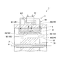
- the cooling unit 6 according to the present embodiment includes a heat exchanger 61 and a cooling channel 64.
- the heat exchanger 61 cools the cooling medium after flowing through the stator 32.
- the cooling flow path 64 supplies the cooling medium circulated through the stator 32 to the heat exchanger 61.
- the cooling flow path 64 allows the cooling medium cooled by the heat exchanger 61 to flow through the stator 32 again.
- a gas such as air or helium is preferably used as the cooling medium.
- a gas such as air or helium By using a gas such as air or helium, the metal material constituting the heat exchanger 61 or the cooling channel 64 is oxidized and the strength is reduced as compared with a gas containing a large amount of liquid such as liquid or water vapor. Can be suppressed.
- the cooling medium As the cooling medium, a part of the compressed fluid compressed by the compressor 2 may be extracted and used.
- the cooling medium can be circulated in the cooling flow path 64 without using a device that sends out the cooling medium such as the pump 653. Therefore, the cooling flow path 64 can be formed with a simple configuration.
- the heat exchanger 61 circulates inside the stator 32 via the cooling flow path 64 and cools the heated cooling medium.
- the heat exchanger 61 of the present embodiment is disposed outside the casing 5.
- the heat exchanger 61 exchanges heat between the surrounding secondary cooling medium and the cooling medium. Thereby, the heat exchanger 61 cools the cooling medium to a temperature suitable for cooling the motor 3.
- the secondary cooling medium when the compressor system 1 is used in a seabed production system and provided on the seabed, it is preferable to use surrounding seawater. By using the surrounding seawater, there is no need to newly prepare a secondary cooling medium for the heat exchanger 61. By using the surrounding seawater, the cooling medium can be cooled to a temperature at which the motor 3 can be sufficiently cooled only by exchanging heat with the seawater at low temperature on the seabed.
- the secondary cooling medium when the compressor system 1 is used in FPSO and provided in a marine facility such as a ship, it is preferable to use ambient air or fresh water stored in the marine facility. . By using ambient air or fresh water, there is no need to newly prepare a secondary cooling medium for the heat exchanger 61. By using ambient air or fresh water, the cooling medium can be cooled to a temperature at which the motor 3 can be sufficiently cooled while suppressing the influence of corrosion of the piping.
- the cooling flow path 64 circulates a cooling medium inside the stator 32 and cools the rotor 31 and the stator 32.
- the cooling flow path 64 of this embodiment is a closed loop flow path for circulating a cooling medium between the heat exchanger 61 and the motor 3, as shown in FIG.
- the cooling flow path 64 has a downstream cooling flow path 65, an intermediate cooling flow path 66, and an upstream cooling flow path 69.
- the downstream cooling passage 65 allows the cooling medium cooled by the heat exchanger 61 to flow inside the stator 32 on the downstream side in the direction of the axis O.
- the intermediate cooling flow channel 66 supplies the cooling medium from the downstream cooling flow channel 65 to the heat exchanger 61 in the middle of the axis O direction and returns to the inside of the stator 32 again.
- the upstream cooling channel 69 is connected to the intermediate cooling channel 66 and allows the cooling medium to flow through the stator 32 on the upstream side in the direction of the axis O.
- the side where the compressor 2 is disposed with respect to the motor 3 in the direction of the axis O is the downstream side in the direction of the axis O (the left side in FIG. 2).
- the opposite end side on the downstream side is the upstream side in the axis O direction (the right side in FIG. 2).
- the downstream cooling flow path 65 has an introduction flow path 651 and a downstream flow path 652.
- the introduction flow path 651 introduces the cooling medium from the heat exchanger 61 into the stator 32 on the downstream side in the axis O direction.
- the downstream flow passage 652 is connected to the introduction flow passage 651 and allows the cooling medium to flow in the direction of the axis O inside the stator 32.
- the introduction flow path 651 introduces the cooling medium cooled by the heat exchanger 61 into the stator 32 from the outside of the casing 5.
- the introduction flow path 651 is a pipe connected from the heat exchanger 61 to the inside of the stator 32 on the downstream side of the stator 32 in the axis O direction.
- the introduction flow path 651 is provided with a pump 653 that pumps the cooling medium in the middle.
- the downstream flow passage 652 is arranged inside the stator 32, thereby allowing the cooling medium to flow inside the stator 32.
- the downstream-side circulation channel 652 of the present embodiment causes the cooling medium to circulate from the downstream side in the axis O direction toward the upstream side.
- the downstream flow passage 652 is a pipe extending in the direction of the axis O at a portion close to the radial rotor 31 inside the stator 32.
- the downstream-side flow passage 652 extends from a position downstream of the rotor 31 in the axis O direction to an intermediate position of the rotor 31 in the axis O direction inside the stator 32.
- the downstream flow channel 652 is connected to the introduction flow channel 651 at the downstream end in the axis O direction.
- the intermediate cooling flow path 66 supplies the heat exchanger 61 with a cooling medium that circulates inside the stator 32 in the middle of the axis O direction inside the stator 32.
- the intermediate cooling flow channel 66 allows the cooling medium cooled by the heat exchanger 61 to flow into the stator 32 again.
- the intermediate cooling channel 66 is formed at an intermediate position of the stator 32 in the axis O direction.
- the intermediate cooling flow channel 66 has an intermediate discharge flow channel 661 and an intermediate introduction flow channel 662.
- the intermediate discharge channel 661 discharges the cooling medium from the interior of the stator 32 in the middle of the direction of the axis O inside the stator 32 and supplies it to the heat exchanger 61.
- the intermediate introduction flow channel 662 introduces a cooling medium from the heat exchanger 61 into the stator 32 in the middle of the axis O direction inside the stator 32.
- the intermediate discharge flow path 661 discharges the coolant whose temperature has risen through the downstream flow path 652 from the inside of the stator 32 to the outside of the casing 5 and supplies it to the heat exchanger 61.
- the intermediate discharge flow path 661 is a pipe connected from the downstream side flow path 652 to the heat exchanger 61 at an intermediate position in the axis O direction of the stator 32.
- the intermediate discharge channel 661 is connected to the upstream end of the downstream flow channel 652 in the axis O direction.
- the intermediate introduction flow path 662 introduces the cooling medium cooled by the heat exchanger 61 from the casing 5 to the stator 32 again.
- the intermediate introduction flow path 662 is a pipe connected from the heat exchanger 61 to the upstream side cooling flow path 69 at an intermediate position in the axis O direction of the stator 32.
- the intermediate introduction flow path 662 is arranged inside the stator 32 with an interval on the upstream side in the axis O direction with respect to the intermediate discharge flow path 661.
- the intermediate introduction channel 662 is formed with the same length as the intermediate discharge channel 661.
- the upstream cooling flow path 69 has an upstream flow path 691 and a discharge flow path 692.
- the upstream-side circulation channel 691 is connected to the intermediate introduction channel 662 and causes the cooling medium to circulate in the direction of the axis O inside the stator 32.
- the discharge flow path 692 is connected to the upstream flow path 691 and supplies the cooling medium flowing through the stator 32 from the upstream side in the direction of the axis O to the heat exchanger 61.
- the upstream flow passage 691 is disposed inside the stator 32, thereby allowing the cooling medium to flow inside the stator 32.
- the upstream flow passage 691 of the present embodiment allows the cooling medium to flow from the downstream side in the axis O direction toward the upstream side.
- the upstream flow passage 691 is a pipe extending in the direction of the axis O at a portion close to the radial rotor 31 inside the stator 32.
- the upstream flow channel 691 is connected to the intermediate introduction flow channel 662 at the downstream end in the direction of the axis O.
- the upstream-side circulation channel 691 is disposed at the same position as the downstream-side circulation channel 652 in the radial direction.
- the upstream circulation passage is disposed upstream of the downstream circulation channel 652 in the direction of the axis O.
- the upstream flow passage 691 extends from an intermediate position in the axis O direction of the rotor 31 to a position upstream of the rotor 31 in the axis O direction inside the stator 32.
- the upstream circulation channel 691 is formed to have the same length as the downstream circulation channel 652.
- the upstream flow passage 691 is formed by sealing the downstream flow passage 652 after being formed integrally with the downstream flow passage 652 with respect to the stator 32.
- the discharge flow path 692 discharges the coolant whose temperature has risen through the upstream flow path 691 from the inside of the stator 32 to the outside of the casing 5 and supplies it to the heat exchanger 61.
- the discharge passage 692 is a pipe connected from the inside of the stator 32 to the heat exchanger 61 on the upstream side of the stator 32 in the direction of the axis O.
- the discharge channel 692 is connected to the upstream end of the upstream flow channel 691 in the axis O direction.
- the compressor system 1 According to the compressor system 1 as described above, current is supplied to the stator 32 by an external device such as a generator (not shown). A rotating magnetic field is generated based on the supplied current, and the rotor 31 of the motor 3 starts rotating together with the shaft 21.
- the impeller 22 By rotating the shaft 21 at a high speed, in the compressor 2, the impeller 22 that rotates together with the shaft 21 compresses the working fluid flowing into the compressor 2 from the upstream side in the axis O direction and compresses from the downstream side in the axis O direction. Drain the compressed fluid.
- the cooling medium cooled by the heat exchanger 61 is introduced into the stator 32 through the introduction flow path 651 and flows through the downstream flow path 652. Therefore, a portion close to the rotor 31 on the downstream side in the axis O direction of the stator 32 is cooled.
- the temperature of the cooling medium rises by cooling the portion of the stator 32 close to the rotor 31.
- the coolant whose temperature has risen is discharged from the downstream flow passage 652 to the outside of the casing 5 via the intermediate discharge passage 661 and supplied to the heat exchanger 61 to be cooled.
- the cooling medium cooled by the heat exchanger 61 is again introduced into the stator 32 through the intermediate introduction flow path 662 and flows through the upstream flow path 691.
- the portion closer to the rotor 31 on the upstream side in the axis O direction than the downstream flow passage 652 of the stator 32 is cooled.
- the temperature of the cooling medium rises by cooling the portion of the stator 32 close to the rotor 31.
- the cooling medium whose temperature has risen is discharged from the upstream flow passage 691 to the outside of the casing 5 via the discharge flow passage 692 and supplied to the heat exchanger 61 again to be cooled.
- the cooling medium cooled by the heat exchanger 61 is again introduced into the stator 32 through the introduction flow path 651 by the pump 653 and flows through the downstream flow path 652. Therefore, when the rotor 31 rotates, the rotor 31 and the stator 32 heated by the heat generated between the rotor 31 and the stator 32 can be cooled in two stages in the direction of the axis O.
- the cooling medium that has flowed through the downstream flow passage 652 and the upstream flow passage 691 is cooled by the heat exchanger 61.
- the cooling medium can be efficiently cooled to a temperature at which the rotor 31 and the stator 32 can be sufficiently cooled.
- the cooling medium that has become a temperature that is not suitable for cooling the rotor 31 and the stator 32 is cooled by exchanging heat with the secondary cooling medium by the heat exchanger 61, thereby efficiently cooling the temperature of the cooling medium. Can be reduced.
- the cooling medium efficiently cooled by the heat exchanger 61 is circulated through the downstream-side circulation channel 652 and the upstream-side circulation channel 691.
- a cooling medium capable of cooling the rotor 31 and the stator 32 with high accuracy can be circulated in the stator 32 along the direction of the axis O. Therefore, when the rotor 31 rotates, the rotor 31 and the stator 32 heated by the heat generated between the rotor 31 and the stator 32 can be efficiently cooled in the direction of the axis O. Thereby, it can suppress that the area
- the coolant whose temperature has risen through the downstream flow passage 652 can be discharged to the outside of the casing 5 and supplied to the heat exchanger 61 by the intermediate discharge flow passage 661.
- the cooling medium cooled by the heat exchanger 61 by the intermediate introduction channel 662 can be circulated to the upstream-side circulation channel 691. Therefore, the cooling medium cooled by the heat exchanger 61 is circulated through the downstream flow passage 652 to reliably cool the downstream side of the rotor 31 and the stator 32 in the direction of the axis O, and from the middle of the direction of the axis O.
- the cooling medium newly cooled again by the heat exchanger 61 can be circulated through the upstream flow passage 691.
- the upstream side of the rotor 31 and the stator 32 in the direction of the axis O can also be reliably cooled. That is, it is possible to prevent the upstream region of the rotor 31 and the stator 32 in the direction of the axis O from being sufficiently cooled. Therefore, the cooling medium cooled by the heat exchanger 61 flows through the downstream-side circulation channel 652 and the upstream-side circulation channel 691. Therefore, it is possible to cool the rotor 31 and the stator 32 while suppressing temperature unevenness occurring in the direction of the axis O. Thereby, it can suppress with high precision that the area
- An intermediate discharge channel 661 and an intermediate introduction channel 662 are formed at an intermediate position in the axis O direction of the stator 32.
- the rotor 31 and the stator 32 can be cooled on the same conditions on the upstream side and the downstream side from the intermediate position in the axis O direction.
- the rotor 31 and the stator 32 are similarly cooled over the axis O direction, and temperature unevenness that occurs in the axis O direction can be suppressed with higher accuracy.
- the cooling flow path 64 is formed as a closed loop flow path, it is not necessary to supply a new cooling medium. Therefore, the flow rate of the cooling medium flowing through the cooling flow path 64 can be suppressed.
- the cooling medium is circulated in the gap 33 between the stator 32 and the rotor 31 (hereinafter simply referred to as the gap 33).
- a plurality of heat exchangers and intermediate cooling flow paths are provided in the direction of the axis O with respect to the stator 32.
- the cooling unit 7 of the second embodiment includes a first heat exchanger 71, a second heat exchanger 72, and a cooling flow path 74, as shown in FIG.
- the first heat exchanger 71 cools the cooling medium on the downstream side in the axis O direction.
- the second heat exchanger 72 cools the cooling medium on the upstream side in the axis O direction.
- the cooling flow path 74 supplies the cooling medium having passed through the gap 33 to the first heat exchanger 71 and the second heat exchanger 72.
- the cooling flow path 74 allows the cooling medium cooled by the first heat exchanger 71 and the second heat exchanger 72 to flow through the gap 33 again.
- the gap 33 in this embodiment is a space formed between the stator 32 and the rotor 31.
- the gap 33 is a space that is sandwiched between surfaces facing each other in the radial direction between the outer peripheral surface facing the radially outer side of the rotor 31 and the inner peripheral surface facing the radially inner side of the stator 32.
- the cooling medium in the cooling unit 7 of the second embodiment and the secondary cooling medium in the first heat exchanger 71 and the second heat exchanger 72 are the same as those in the first embodiment.
- the first heat exchanger 71 an apparatus similar to the heat exchanger 61 of the first embodiment is used.
- the first heat exchanger 71 is disposed outside the casing 5.
- the second heat exchanger 72 is disposed outside the casing 5 on the upstream side in the axis O direction from the first heat exchanger 71.
- the second heat exchanger 72 uses the same device as the heat exchanger 61 and the first heat exchanger 71 of the first embodiment.
- the cooling flow path 74 of the second embodiment cools the rotor 31 and the stator 32 by circulating a cooling medium through the gap 33.
- the cooling flow path 74 of the second embodiment is a closed loop flow path for circulating the cooling medium between the first heat exchanger 71 and the second heat exchanger 72 and the motor 3.
- the cooling channel 74 includes a downstream cooling channel 75, a first intermediate cooling channel 76, an intermediate circulation channel 77, a second intermediate cooling channel 78, an upstream cooling channel 79, and a connection channel. 80.
- the downstream side cooling flow path 75 causes the cooling medium cooled by the first heat exchanger 71 to flow through the gap 33 on the downstream side in the direction of the axis O.
- the first intermediate cooling flow path 76 supplies the cooling medium from the downstream cooling flow path 75 to the first heat exchanger 71 in the middle of the axis O direction and returns it to the gap 33 again.
- the intermediate flow passage 77 is connected to the first intermediate cooling flow passage 76 and allows the cooling medium to flow through the gap 33 in the middle of the axis O direction.
- the second intermediate cooling channel 78 supplies the cooling medium from the first intermediate cooling channel 76 to the second heat exchanger 72 and returns it to the gap 33 again.
- the upstream cooling flow path 79 is connected to the second intermediate cooling flow path 78 and causes the cooling medium to flow through the gap 33 on the upstream side in the direction of the axis O.
- the connection channel 80 connects the first heat exchanger 71 and the second heat exchanger 72.
- the downstream cooling channel 75 of the second embodiment has an introduction channel 751 and a downstream circulation channel 752.
- the introduction flow path 751 introduces the cooling medium from the first heat exchanger 71 into the gap 33 on the downstream side in the axis O direction.
- the downstream-side circulation channel 752 is connected to the introduction channel 751 and extends in the direction of the axis O through the gap 33.
- the introduction flow path 751 of the second embodiment introduces the cooling medium cooled by the first heat exchanger 71 into the gap 33.
- the introduction flow path 751 is a pipe connected from the heat exchanger 61 to the gap 33 on the downstream side in the direction of the axis O.
- the introduction flow path 751 is provided with a pump 653 that pumps the cooling medium in the middle.
- the downstream flow passage 752 of the second embodiment is arranged in the gap 33 so that the cooling medium flows through the gap 33.
- the downstream-side circulation channel 752 of this embodiment allows the cooling medium to circulate from the downstream side in the axis O direction toward the upstream side.
- the downstream flow passage 752 is a pipe extending in the direction of the axis O with the gap 33.
- the downstream-side circulation channel 752 is connected to the introduction channel 751 at the downstream end in the axis O direction.
- the downstream-side flow passage 752 is formed to have a length that is about one third of the length of the rotor 31 in the axis O direction from the position downstream of the rotor 31 in the axis O direction.
- the first intermediate cooling flow path 76 supplies the cooling medium flowing through the gap 33 to the first heat exchanger 71 in the middle of the gap 33 in the direction of the axis O.
- the first intermediate cooling flow path 76 allows the cooling medium cooled by the first heat exchanger 71 to flow again into the gap 33 in the middle of the gap 33 in the direction of the axis O.
- the first intermediate cooling flow path 76 is formed in the middle of the gap 33 in the direction of the axis O.
- the first intermediate cooling flow path 76 includes a first intermediate discharge flow path 761 and a first intermediate introduction flow path 762.
- the first intermediate discharge flow path 761 discharges the cooling medium from the gap 33 in the middle of the gap 33 in the direction of the axis O and supplies it to the first heat exchanger 71.
- the first intermediate introduction flow path 762 introduces the cooling medium from the first heat exchanger 71 into the gap 33 in the middle of the gap 33 in the axis O direction.
- the first intermediate discharge flow path 761 discharges the coolant whose temperature has risen through the downstream flow path 752 from the gap 33 to the outside of the casing 5 and supplies it to the first heat exchanger 71.
- the first intermediate discharge channel 761 is a pipe connected from the upstream end of the downstream flow channel 752 in the direction of the axis O to the first heat exchanger 71.
- the first intermediate introduction flow path 762 introduces the cooling medium cooled by the first heat exchanger 71 from the outside of the casing 5 to the gap 33 again.
- the first intermediate introduction channel 762 is a pipe connected from the heat exchanger 61 to the intermediate flow channel 77.
- the first intermediate introduction flow path 762 is arranged inside the stator 32 with a gap on the upstream side in the axis O direction with respect to the first intermediate discharge flow path 761.
- the first intermediate introduction flow path 762 is formed with the same length as the first intermediate discharge flow path 761.
- the intermediate flow channel 77 is arranged in the gap 33 so that the cooling medium flows through the gap 33.
- the intermediate flow channel 77 of the present embodiment allows the cooling medium to flow from the downstream side in the axis O direction toward the upstream side.
- the intermediate flow path 77 is a pipe that extends in the direction of the axis O with a gap 33.
- the intermediate flow path 77 is connected to the first intermediate introduction flow path 762 at the downstream end in the axis O direction.
- the intermediate flow channel 77 is disposed in the gap 33 on the upstream side in the axis O direction with respect to the downstream flow channel 752.
- the intermediate flow path 77 is formed to have a length that is about one third of the length of the rotor 31 in the direction of the axis O. That is, the intermediate flow channel 77 is formed with the same length as the downstream flow channel 752.
- the second intermediate cooling flow path 78 supplies the cooling medium flowing through the gap 33 to the second heat exchanger 72 in the middle of the gap 33 in the axis O direction.
- the second intermediate cooling channel 78 allows the cooling medium cooled by the second heat exchanger 72 to flow again into the gap 33 in the middle of the gap 33 in the direction of the axis O.
- the second intermediate cooling flow path 78 is formed in the middle of the gap 33 in the direction of the axis O and upstream of the first intermediate cooling flow path 76 in the direction of the axis O.
- the second intermediate cooling flow path 78 has a second intermediate discharge flow path 781 and a second intermediate introduction flow path 782.
- the second intermediate discharge flow path 781 discharges the cooling medium from the gap 33 in the middle of the gap 33 in the direction of the axis O and supplies it to the second heat exchanger 72.
- the second intermediate introduction channel 782 introduces the cooling medium from the second heat exchanger 72 to the gap 33 in the middle of the gap 33 in the axis O direction.
- the second intermediate discharge channel 781 discharges the coolant whose temperature has risen through the intermediate flow channel 77 from the gap 33 to the outside of the casing 5 and supplies it to the second heat exchanger 72.
- the second intermediate discharge channel 781 is a pipe connected from the upstream end of the intermediate flow channel 77 in the direction of the axis O to the second heat exchanger 72. That is, the second intermediate discharge channel 781 is arranged upstream of the first intermediate introduction channel 762 in the axis O direction.
- the second intermediate introduction channel 782 introduces the cooling medium cooled by the second heat exchanger 72 into the gap 33 again.
- the second intermediate introduction channel 782 is a pipe connected from the second heat exchanger 72 to the upstream side cooling channel 79.
- the second intermediate introduction flow path 782 is arranged in the stator 32 side by side with an interval on the upstream side in the direction of the axis O with respect to the second intermediate discharge flow path 781.
- the second intermediate introduction channel 782 is formed with the same length as the second intermediate discharge channel 781.
- the upstream cooling flow path 79 has an upstream flow path 791 and a discharge flow path 792.
- the upstream-side flow channel 791 is connected to the second intermediate introduction channel 782 and extends in the direction of the axis O through the gap 33.
- the discharge flow path 792 is connected to the upstream flow path 791 and supplies the cooling medium flowing through the gap 33 from the upstream side in the direction of the axis O to the second heat exchanger 72.
- the upstream circulation flow path 791 is arranged in the gap 33 so that the cooling medium flows through the gap 33.
- the upstream-side circulation channel 791 of the present embodiment causes the cooling medium to circulate from the downstream side in the axis O direction toward the upstream side.
- the upstream flow passage 791 is a pipe that extends in the direction of the axis O through the gap 33.
- the upstream circulation channel 791 is connected to the second intermediate introduction channel 782 at the downstream end in the axis O direction.
- An upstream end of the upstream flow passage 791 is connected to the discharge flow passage 792.
- the upstream circulation channel 791 is disposed at the same radial position as the downstream circulation channel 752 and the intermediate circulation channel 77.
- the upstream flow passage 791 is disposed on the upstream side in the axis O direction with respect to the intermediate flow passage 77.
- the upstream flow passage 791 is formed to have a length that is about one third of the length of the rotor 31 in the axis O direction. That is, the upstream circulation channel 791 is formed to have the same length as the downstream circulation channel 752 and the intermediate circulation channel 77.
- the discharge flow path 792 discharges the coolant whose temperature has risen through the upstream flow path 791 from the gap 33 to the outside of the casing 5 and supplies it to the second heat exchanger 72.
- the discharge flow path 792 is a pipe connected from the inside of the stator 32 to the second heat exchanger 72 on the upstream side in the axis O direction of the stator 32.
- the discharge channel 792 is connected to the upstream end of the upstream flow channel 791 in the axis O direction.
- connection flow path 80 supplies the cooling medium cooled by the second heat exchanger 72 to the first heat exchanger 71.
- the connection channel 80 is a pipe that connects the first heat exchanger 71 and the second heat exchanger 72 outside the casing 5.
- the cooling medium cooled by the first heat exchanger 71 is introduced into the gap 33 through the introduction flow path 751 and flows through the downstream flow path 752. Therefore, the downstream side periphery of the gap 33 in the direction of the axis O is cooled. By cooling the periphery of the gap 33 on the downstream side in the axis O direction, the temperature of the cooling medium rises.
- the coolant whose temperature has risen is discharged from the downstream flow passage 752 to the outside of the casing 5 via the first intermediate discharge passage 761 and supplied to the first heat exchanger 71 to be cooled.
- the cooling medium cooled by the first heat exchanger 71 is again introduced into the gap 33 via the first intermediate introduction flow path 762 and flows through the intermediate flow path 77. Therefore, the vicinity of the vicinity of the middle in the axis O direction of the gap 33 that is upstream in the axis O direction with respect to the downstream flow passage 752 is cooled. By cooling the vicinity of the middle of the gap 33 in the direction of the axis O, the temperature of the cooling medium rises.
- the coolant whose temperature has risen is discharged from the intermediate flow passage 77 to the outside of the casing 5 via the second intermediate discharge passage 781 and supplied to the second heat exchanger 72 to be cooled.
- the cooling medium cooled by the second heat exchanger 72 is again introduced into the gap 33 through the second intermediate introduction flow path 782 and flows through the upstream flow flow path 791. Therefore, the vicinity of the upstream side in the axis O direction of the gap 33 that is upstream in the axis O direction from the intermediate flow path 77 is cooled.
- the temperature of the cooling medium increases.
- the cooling medium whose temperature has risen is discharged from the upstream flow passage 791 to the outside of the casing 5 through the discharge flow passage 792 and supplied again to the second heat exchanger 72 to be cooled.
- the cooling medium cooled by the second heat exchanger 72 flows through the connection channel 80, is supplied to the first heat exchanger 71, and is further cooled.
- the cooling medium cooled by the first heat exchanger 71 is again introduced into the stator 32 through the introduction flow path 751 by the pump 653 and flows through the downstream flow flow path 752. Therefore, the rotor 31 and the stator 32 heated by the heat generated between the rotor 31 and the stator 32 can be cooled in three stages in the direction of the axis O.
- the first intermediate cooling channel 76 and the second intermediate cooling channel 78 are provided. Thereby, the cooling medium whose temperature has risen at a plurality of locations in the direction of the axis O with respect to the gap 33 can be cooled again by the first heat exchanger 71 and the second heat exchanger 72. Therefore, the newly cooled cooling medium can be circulated at two places in the direction of the axis O in the gap 33. Therefore, the cooling efficiency of the rotor 31 and the stator 32 can be further improved in the direction of the axis O.
- the cooling medium can be circulated in the gap 33. Therefore, the cooling medium can be circulated closer to the rotor 31 than when the cooling medium is circulated inside the stator 32. Therefore, the cooling efficiency of the rotor 31 can be improved.
- the heat exchanger is not limited to being disposed outside the casing 5 as in the present embodiment, and it is sufficient that the cooling medium can be cooled.
- the heat exchanger 61, the first heat exchanger 71, and the second heat exchanger 72 may be disposed inside the casing 5.
- the heat exchanger 61 is not limited to one in the first embodiment. Two heat exchangers 61 may be provided as in the second embodiment, or three or more heat exchangers 61 may be provided.
- the intermediate cooling flow path is equal to the intermediate position of the stator 32 as in the intermediate cooling flow path 66 of the first embodiment, and the same as the first intermediate cooling flow path 76 and the second intermediate cooling flow path 78 of the second embodiment. It is not limited to being arranged in.
- the intermediate cooling flow path may be non-uniformly arranged with respect to the stator 32 in accordance with a place where cooling is necessary.
- the number of intermediate cooling channels is not limited to two as in the second embodiment, and three or more intermediate cooling channels may be provided.
- the cooling unit 6 ⁇ / b> A of the third embodiment cools the rotor 31 and the stator 32.
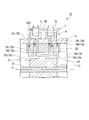
- the cooling unit 6 ⁇ / b> A of the present embodiment includes a heat exchanger 61 ⁇ / b> A, a first internal flow path (first flow path) 62, and a second internal flow path (second flow path) 63. And have.
- the heat exchanger 61A cools the cooling medium after flowing through the stator 32.
- the first internal flow path 62 circulates the cooling medium circulated through the stator 32 and circulates it again into the stator 32.
- the second internal channel 63 is adjacent to the first internal channel 62 with an interval in the direction of the axis O.
- the second internal channel 63 circulates the cooling medium that has circulated through the stator 32 and circulates it again into the stator 32.
- a gas such as air or helium is preferably used as the cooling medium.
- a gas such as air or helium By using a gas such as air or helium, the metal material constituting the heat exchanger 61A, the first internal flow path 62, or the second internal flow path 63 as compared with a gas containing a large amount of liquid such as liquid or water vapor. It can be suppressed that the strength is lowered due to oxidation.
- the cooling medium As the cooling medium, a part of the compressed fluid compressed by the compressor 2 may be extracted and used.
- the cooling medium can be circulated in the first internal flow path 62 or the second internal flow path 63 without using a device that sends out the cooling medium such as the pump 621a. it can. Therefore, the first internal channel 62 and the second internal channel 63 can be formed with a simple configuration.
- the heat exchanger 61A circulates inside the stator 32 through the first internal flow path 62 and the second internal flow path 63, and cools the heated cooling medium.
- the heat exchanger 61 ⁇ / b> A of the present embodiment is disposed outside the casing 5.
- the heat exchanger 61A exchanges heat between the surrounding secondary cooling medium and the cooling medium. Thereby, the heat exchanger 61A cools the cooling medium to a temperature suitable for cooling the motor 3.
- the heat exchanger 61 ⁇ / b> A cools the cooling medium flowing through the first internal flow path 62 and cools the cooling medium flowing through the second internal flow path 63. That is, in the present embodiment, only one heat exchanger 61 ⁇ / b> A is provided for the first internal channel 62 and the second internal channel 63.
- the secondary cooling medium when the compressor system 1 is used in a seabed production system and is provided on the seabed, surrounding seawater is preferably used. By using the surrounding seawater, there is no need to newly prepare a secondary cooling medium for the heat exchanger 61A. By using the surrounding seawater, the cooling medium can be cooled to a temperature at which the motor 3 can be sufficiently cooled only by exchanging heat with the seawater at low temperature on the seabed.
- the secondary cooling medium when the compressor system 1 is used for FPSO and provided in a marine facility such as a ship, it is preferable to use ambient air or fresh water stored in the marine facility. . By using ambient air or fresh water, there is no need to newly prepare a secondary cooling medium for the heat exchanger 61A. By using ambient air or fresh water, the cooling medium can be cooled to a temperature at which the motor 3 can be sufficiently cooled while suppressing the influence of corrosion of the piping.
- the first internal flow path 62 circulates a cooling medium inside the stator 32 and cools the rotor 31 and the stator 32.
- the first internal channel 62 of the present embodiment is a closed loop channel that circulates the cooling medium between the heat exchanger 61 ⁇ / b> A and the motor 3.
- the first internal channel 62 is disposed on the downstream side of the center position of the stator 32 in the axis O direction.
- the side on which the compressor 2 is disposed with respect to the motor 3 in the direction of the axis O is the downstream side (the left side in FIG. 4) which is one side in the direction of the axis O.
- the opposite end side on the downstream side is the upstream side (the right side in FIG. 4) which is the other side in the direction of the axis O.
- the first internal flow path 62 of the present embodiment circulates the cooling medium from the upstream side in the axis O direction toward the downstream side within the stator 32.
- the first internal flow path 62 includes a first internal introduction flow path 621, a first internal circulation flow path 622, and a first internal discharge flow path 623.
- the first internal introduction flow path 621 introduces the cooling medium cooled by the heat exchanger 61A into the stator 32 from the middle in the direction of the axis O.
- the first internal flow channel 622 is connected to the first internal introduction flow channel 621 and allows the cooling medium to flow in the direction of the axis O inside the stator 32.
- the first internal discharge channel 623 is connected to the first internal flow channel 622, discharges the cooling medium from the inside of the stator 32, and supplies it to the heat exchanger 61A.
- the first internal introduction flow path 621 introduces the cooling medium cooled by the heat exchanger 61A from the outside of the casing 5 into the stator 32.
- the first internal introduction flow path 621 is a pipe connected from the heat exchanger 61 ⁇ / b> A to the inside of the stator 32 at an intermediate position in the axis O direction of the stator 32.
- the first internal introduction flow path 621 is provided with a pump 621a that pumps the cooling medium in the middle.
- the first internal flow channel 622 is arranged inside the stator 32 so that the cooling medium flows inside the stator 32.
- the first internal circulation channel 622 of the present embodiment distributes the cooling medium from the upstream side in the direction of the axis O toward the downstream side.
- the first internal flow passage 622 is a pipe extending in the direction of the axis O at a portion close to the radial rotor 31 inside the stator 32.
- the first internal flow channel 622 extends from an intermediate position in the axis O direction of the rotor 31 to a position downstream of the rotor 31 in the axis O direction inside the stator 32.
- the first internal circulation flow path 622 is connected to the first internal introduction flow path 621 at the upstream end in the axis O direction.
- the first internal discharge flow path 623 discharges the coolant whose temperature has risen through the first internal flow path 622 from the inside of the stator 32 to the outside of the casing 5 and supplies it to the heat exchanger 61A.
- the first internal discharge flow path 623 is a pipe connected from the first internal flow path 622 to the heat exchanger 61A on the downstream side of the stator 32 in the axis O direction.
- the first internal discharge flow channel 623 is connected to the downstream end of the first internal flow flow channel 622 in the axis O direction.
- the second internal flow path 63 circulates a cooling medium in the stator 32 on the upstream side in the axis O direction from the first internal flow path 62, and cools the rotor 31 and the stator 32.
- the second internal flow path 63 of the present embodiment is a closed loop flow path for circulating the cooling medium between the heat exchanger 61 ⁇ / b> A and the motor 3, and is independent of the first internal flow path 62.
- the second internal flow path 63 is arranged at a distance from the first internal flow path 62 in the axis O direction.
- the second internal flow path 63 is disposed upstream of the center position of the stator 32 in the axis O direction.
- the second internal flow path 63 is formed with the same length as the first internal flow path 62.
- the flow direction of the cooling medium is opposite to that of the first internal flow channel 62.
- the second internal flow channel 632 allows the cooling medium to flow from the downstream side in the axis O direction toward the upstream side within the stator 32.
- the second internal flow path 63 has a second internal introduction flow path 631, a second internal circulation flow path 632, and a second internal discharge flow path 633.
- the second internal introduction flow path 631 introduces the cooling medium cooled by the heat exchanger 61A into the stator 32 from the middle in the direction of the axis O.
- the second internal flow channel 632 is connected to the second internal introduction flow channel 631 and allows the cooling medium to flow in the direction of the axis O inside the stator 32.
- the second internal discharge flow path 633 is connected to the second internal flow path 632, discharges the cooling medium from the stator 32, and supplies it to the heat exchanger 61A.
- the second internal introduction flow path 631 introduces the cooling medium cooled by the heat exchanger 61A from the outside of the casing 5 into the stator 32.
- the second internal introduction flow path 631 is a pipe connected from the heat exchanger 61 ⁇ / b> A to the inside of the stator 32 at an intermediate position in the axis O direction of the stator 32.
- the second internal introduction flow path 631 is disposed with a space on the upstream side in the axis O direction with respect to the first internal introduction flow path 621.
- the second internal introduction flow path 631 is provided with a pump 621a that pumps the cooling medium in the middle.
- the second internal introduction flow path 631 is formed with the same length as the first internal introduction flow path 621.
- the second internal circulation channel 632 is arranged inside the stator 32, thereby circulating the cooling medium inside the stator 32.
- the second internal circulation channel 632 of this embodiment distributes the cooling medium from the downstream side in the axis O direction toward the upstream side.
- the second internal circulation channel 632 is a pipe extending in the direction of the axis O at a portion close to the radial rotor 31 inside the stator 32.
- the second internal circulation flow path 632 is connected to the second internal introduction flow path 631 at the downstream end in the axis O direction.
- the second internal circulation channel 632 extends from an intermediate position in the axis O direction of the rotor 31 to a position upstream of the rotor 31 in the axis O direction inside the stator 32.
- the second internal circulation channel 632 extends toward the opposite side of the axis O direction from the first internal circulation channel 622.
- the second internal flow channel 632 is disposed at the same radial position as the first internal flow channel 622.
- the second internal flow passage is formed with the same length as the first internal flow passage 622.
- the second internal circulation channel 632 is formed by sealing the space between the second internal circulation channel 622 and the first internal circulation channel 622 after being formed integrally with the stator 32.
- the second internal discharge flow path 633 discharges the coolant whose temperature has risen through the second internal flow path 632 from the inside of the stator 32 to the outside of the casing 5 and supplies it to the heat exchanger 61A.
- the second internal discharge channel 633 is a pipe connected from the second internal circulation channel 632 to the heat exchanger 61 ⁇ / b> A on the upstream side in the axis O direction of the stator 32.
- the second internal discharge channel 633 is connected to the upstream end of the second internal flow channel 632 in the direction of the axis O.
- the second internal discharge channel 633 is formed to have the same length as the first internal discharge channel 623.
- the compressor system 1 According to the compressor system 1 as described above, current is supplied to the stator 32 by an external device such as a generator (not shown). A rotating magnetic field is generated based on the supplied current, and the rotor 31 of the motor 3 starts rotating together with the shaft 21.
- the impeller 22 By rotating the shaft 21 at a high speed, in the compressor 2, the impeller 22 that rotates together with the shaft 21 compresses the working fluid flowing into the compressor 2 from the upstream side in the axis O direction and compresses from the downstream side in the axis O direction. Drain the compressed fluid.
- the cooling medium cooled by the heat exchanger 61 ⁇ / b> A is introduced into the stator 32 through the first internal introduction flow path 621 and flows through the first internal flow path 622. Thereby, a portion close to the rotor 31 on the downstream side in the direction of the axis O of the stator 32 is cooled.
- the temperature of the cooling medium rises by cooling the portion of the stator 32 close to the rotor 31.
- the cooling medium whose temperature has risen is discharged from the first internal circulation flow path 622 to the outside of the casing 5 through the first internal discharge flow path 623, and supplied to the heat exchanger 61A to be cooled.
- the cooling medium cooled by the heat exchanger 61 ⁇ / b> A is again introduced into the stator 32 through the first internal introduction flow path 621 by the pump 621 a and flows through the first internal flow path 622.
- the cooling medium cooled by the heat exchanger 61 A is introduced into the stator 32 through the second internal introduction flow path 631 and flows through the second internal flow path 632.
- a portion closer to the rotor 31 on the upstream side in the axis O direction than the first internal circulation channel 622 of the stator 32 is cooled.
- the temperature of the cooling medium rises by cooling the portion of the stator 32 close to the rotor 31.
- the coolant whose temperature has risen is discharged from the second internal circulation flow path 632 to the outside of the casing 5 via the second internal discharge flow path 633, and supplied to the heat exchanger 61A to be cooled.
- the cooling medium cooled by the heat exchanger 61 ⁇ / b> A is again introduced into the stator 32 through the second internal introduction flow path 631 by the pump 621 a and flows through the second internal flow path 632.
- the rotor 31 and the stator 32 on the downstream side in the axis O direction are cooled by the cooling medium flowing through the first internal flow passage 622, and at the same time, the cooling medium flowing through the second internal flow passage 632 is used in the direction of the axis O.
- the upstream rotor 31 and the stator 32 can be cooled. Therefore, the first internal flow channel 622 and the second internal flow channel 632 divide the rotor 31 and the stator 32 that are long in the direction of the axis O into a downstream region and an upstream region in the direction of the axis O. Can be cooled separately.
- the temperature of the cooling medium is increased by cooling the rotor 31 and the stator 32 on the downstream side in the axis O direction.
- the region to be cooled is divided into the direction of the axis O, and the rotor 31 and the stator 32 are cooled by the cooling medium flowing through another system. Thereby, it can suppress that the area
- the cooling medium flowing through the first internal flow channel 622 and the second internal flow channel 632 is cooled by the heat exchanger 61A. Therefore, the cooling medium can be efficiently cooled to a temperature at which the rotor 31 and the stator 32 can be sufficiently cooled. That is, the cooling medium that has become a suitable temperature for cooling the rotor 31 and the stator 32 can be cooled by exchanging heat with the secondary cooling medium by the heat exchanger 61A. Thereby, the temperature of a cooling medium can be reduced efficiently.
- the cooling medium efficiently cooled by the heat exchanger 61 ⁇ / b> A is circulated through the first internal circulation channel 622 and the second internal circulation channel 632.
- a cooling medium capable of cooling the rotor 31 and the stator 32 with high accuracy can be circulated in the stator 32 along the axis O direction. Therefore, when the rotor 31 rotates, the rotor 31 and the stator 32 heated by the heat generated between the rotor 31 and the stator 32 can be efficiently cooled in the direction of the axis O. Thereby, it can suppress that the area
- first internal flow path 62 and the second internal flow path 63 are configured with a small number of configurations. Can be configured.
- the flow direction of the cooling medium in the first internal flow path 62 and the second internal flow path 63 is opposite.
- the cooling medium flowing through the radially extending flow path such as the first internal introduction flow path 621 and the second internal introduction flow path 631 arranged at the intermediate position in the axis O direction closest to the axis O direction.
- the distribution direction can be the same direction. Therefore, heat exchange occurs between the cooling media flowing through the flow paths formed at positions closest to the direction of the axis O, and the influence can be suppressed.
- the first internal flow path 62 and the second internal flow path 63 are formed with the same length as in the present embodiment and the temperature conditions of the fluid flowing through the inside are the same, it is more effective. The influence when heat exchange occurs can be suppressed.
- the first internal flow path 622 and the first internal flow path 622 are sealed to form the first internal flow path 62 and the second internal flow path 63 separately.
- the first internal flow path 62 and the second internal flow path 63 may be integrally formed. This is because the flow direction of the cooling medium is reversed, so that the radial direction formed at the closest position in the axis O direction as in the first internal introduction flow path 621 and the second internal introduction flow path 631. This is because the flow direction of the cooling medium flowing through the flow path extending in the same direction is the same. Therefore, the first internal channel 62 and the second internal channel 63 can be formed with a small number of man-hours.
- first internal flow path 62 and the second internal flow path 63 are formed as closed loop flow paths, there is no need to supply a new cooling medium. Therefore, the flow rate of the cooling medium flowing through the first internal channel 62 and the second internal channel 63 can be suppressed.
- ⁇ 4th embodiment >> Next, the compressor system 10 of 4th embodiment is demonstrated with reference to FIG.
- the same components as those in the first embodiment to the third embodiment are denoted by the same reference numerals, and detailed description thereof is omitted.
- the compressor system 10 according to the fourth embodiment is different from the first embodiment in the configuration of the cooling unit 7 from the first embodiment.
- the cooling medium is circulated in the gap 33 between the stator 32 and the rotor 31 (hereinafter simply referred to as the gap 33).
- the flow direction of the cooling medium flowing through the first flow path and the second flow path is different from that of the first embodiment.
- the cooling unit 7 ⁇ / b> A of the second embodiment includes a heat exchanger 61 ⁇ / b> A similar to the third embodiment, a first gap channel (first channel) 72 ⁇ / b> A, And a gap channel (second channel) 73A.
- the first gap flow path 72 ⁇ / b> A circulates the cooling medium that has circulated through the gap 33 formed between the stator 32 and the rotor 31, and circulates again through the gap 33.
- the second gap channel 73A is adjacent to the first gap channel 72A with an interval in the direction of the axis O.
- the second gap flow path 73 ⁇ / b> A circulates the cooling medium that has circulated through the gap 33 and circulates it through the gap 33 again.
- the gap 33 in the present embodiment is a space formed between the stator 32 and the rotor 31.
- the gap 33 is a space that is sandwiched between surfaces facing each other in the radial direction between the outer peripheral surface facing the radially outer side of the rotor 31 and the inner peripheral surface facing the radially inner side of the stator 32.
- the first gap flow path 72 ⁇ / b> A cools the rotor 31 and the stator 32 by circulating a cooling medium through the gap 33.
- the first gap flow path 72 ⁇ / b> A is a closed loop flow path for circulating the cooling medium between the heat exchanger 61 ⁇ / b> A and the motor 3.
- the first gap flow path 72A is disposed on the downstream side of the center position of the stator 32 in the axis O direction.
- 72 A of 1st clearance channels distribute
- the first gap channel 72A includes a first gap introduction channel 721, a first gap circulation channel 722, and a first gap discharge channel 723.
- the first gap introduction channel 721 introduces the cooling medium cooled by the heat exchanger 61A into the gap 33 from the middle in the direction of the axis O.
- the first gap circulation channel 722 is connected to the first gap introduction channel 721 and causes the cooling medium to flow in the direction of the axis O through the gap 33.
- the first gap discharge channel 723 is connected to the first gap flow channel 722, discharges the cooling medium from the gap 33, and supplies it to the heat exchanger 61A.
- the first gap introduction channel 721 introduces the cooling medium cooled by the heat exchanger 61 ⁇ / b> A into the gap 33 from the outside of the casing 5.
- the first gap introduction channel 721 is a pipe connected from the heat exchanger 61 ⁇ / b> A to the gap 33 on the downstream side of the stator 32 in the axis O direction.
- the first gap introduction flow path 721 is provided with a pump 621a that pumps the cooling medium in the middle.
- the first gap circulation channel 722 is arranged in the gap 33 so that the cooling medium flows through the gap 33.
- the first gap circulation channel 722 of the present embodiment causes the cooling medium to flow from the downstream side in the axis O direction toward the upstream side.
- the first gap circulation channel 722 is a pipe that extends in the direction of the axis O through the gap 33.
- the first gap circulation channel 722 extends in the gap 33 from an intermediate position of the rotor 31 in the axis O direction to a position downstream of the rotor 31 in the axis O direction.
- the first gap circulation channel 722 is connected to the first gap introduction channel 721 at the downstream end in the axis O direction.
- the first gap discharge flow path 723 discharges the cooling medium whose temperature has risen through the first gap flow path 722 to the outside of the casing 5 from the gap 33 and supplies it to the heat exchanger 61A.
- the first clearance discharge channel 723 is a pipe connected from the first clearance flow channel 722 to the heat exchanger 61 ⁇ / b> A at an intermediate position in the axis O direction of the stator 32.
- the first clearance discharge channel 723 is connected to the upstream end of the first clearance flow channel 722 in the axis O direction.
- the second gap flow path 73A causes the cooling medium to flow through the gap 33 on the upstream side in the axis O direction from the first gap flow path 72A, thereby cooling the rotor 31 and the stator 32.
- the second gap channel 73A of the present embodiment is a closed loop channel that circulates the cooling medium between the heat exchanger 61A and the motor 3, and is independent of the first gap channel 72A.
- the second gap channel 73A is disposed with a gap in the direction of the axis O from the first gap channel 72A.
- the second gap flow path 73A is disposed on the upstream side of the center position of the stator 32 in the axis O direction.
- the second gap channel 73A of the present embodiment the flow direction of the cooling medium is opposite to that of the first gap channel 72A.
- the second gap flow path 73A allows the cooling medium to flow through the gap 33 from the upstream side in the direction of the axis O toward the downstream side.
- the second gap channel 73 ⁇ / b> A includes a second gap introduction channel 731, a second gap circulation channel 732, and a second gap discharge channel 733.
- the second gap introduction channel 731 introduces the cooling medium cooled by the heat exchanger 61A into the gap 33 from the upstream side in the axis O direction.
- the second gap circulation channel 732 is connected to the second gap introduction channel 731 and causes the cooling medium to flow in the direction of the axis O through the gap 33.
- the second gap discharge channel 733 is connected to the second gap circulation channel 732, discharges the cooling medium from the gap 33, and supplies it to the heat exchanger 61A.
- the second gap channel 73A has the same length as the first gap channel
- the second gap introduction channel 731 introduces the cooling medium cooled by the heat exchanger 61 ⁇ / b> A into the gap 33 from the outside of the casing 5.
- the second gap introduction flow path 731 is a pipe connected from the heat exchanger 61 ⁇ / b> A to the gap 33 on the upstream side in the axis O direction of the stator 32.
- the second gap introduction channel 731 is provided with a pump 621a that pumps the cooling medium in the middle.
- the second gap circulation channel 732 is arranged in the gap 33 so that the cooling medium flows through the gap 33.
- the second clearance circulation channel 732 of the present embodiment distributes the cooling medium from the upstream side in the axis O direction toward the downstream side.
- the second gap flow channel 732 is a pipe that extends in the direction of the axis O through the gap 33.
- the second gap circulation channel 732 is connected to the second gap introduction channel 731 at the upstream end in the axis O direction.
- the second gap circulation channel 732 extends in the gap 33 from an intermediate position of the rotor 31 in the axis O direction to a position upstream of the rotor 31 in the axis O direction.
- the second gap circulation channel 732 extends toward the opposite side of the axis O direction from the first gap circulation channel 722.
- the second gap circulation channel 732 is disposed in the same position as the first gap circulation channel 722 in the radial direction.
- the second gap circulation channel 732 is formed to have the same length as the first gap circulation channel 722.
- the second gap discharge channel 733 discharges the coolant whose temperature has risen through the second gap circulation channel 732 to the outside of the casing 5 from the gap 33 and supplies it to the heat exchanger 61A.
- the second clearance discharge channel 733 is a pipe connected from the second clearance flow channel 732 to the heat exchanger 61 ⁇ / b> A at an intermediate position in the axis O direction of the stator 32.
- the second clearance discharge channel 733 is connected to the downstream end of the second clearance flow channel 732 in the axis O direction.
- the second gap discharge channel 733 is arranged with an interval on the upstream side in the axis O direction with respect to the first gap discharge channel 723.
- the second gap discharge channel 733 is formed to have the same length as the first gap discharge channel 723.
- the rotor 31 and the stator 32 that are long in the direction of the axis O are provided by the first gap circulation channel 722 and the second gap circulation channel 732. It is possible to cool separately by dividing the area into a downstream area and an upstream area in the direction of the axis O. Therefore, the region to be cooled can be divided into the direction of the axis O, and the rotor 31 and the stator 32 can be cooled by the cooling medium flowing through another system. As a result, it is possible to suppress the occurrence of a region that is not sufficiently cooled.
- the cooling medium can be circulated in the gap 33. Therefore, the cooling medium can be circulated closer to the rotor 31 than when the cooling medium is circulated inside the stator 32. Therefore, the cooling efficiency of the rotor 31 can be improved.
- the heat exchanger 61A is not limited to being disposed outside the casing 5 as in the present embodiment, as long as the cooling medium can be cooled.
- the heat exchanger 61 ⁇ / b> A may be disposed inside the casing 5.
- the number of heat exchangers 61A is not limited to one, and a plurality of heat exchangers 61A may be provided.
- a flow path for circulating a plurality of cooling media such as a third flow path and a fourth flow path that are separated in the direction of the axis O It may be done.
- the flow direction of the cooling medium in the first flow path and the second flow path is not limited to the reverse direction, and may be the same direction.
- the rotor and the stator can be effectively cooled by circulating the cooling medium through the first flow path and the second flow path formed apart in the axial direction.
Landscapes
- Engineering & Computer Science (AREA)
- Mechanical Engineering (AREA)
- General Engineering & Computer Science (AREA)
- Power Engineering (AREA)
- Mining & Mineral Resources (AREA)
- Life Sciences & Earth Sciences (AREA)
- Geology (AREA)
- Physics & Mathematics (AREA)
- Environmental & Geological Engineering (AREA)
- Fluid Mechanics (AREA)
- General Life Sciences & Earth Sciences (AREA)
- Geochemistry & Mineralogy (AREA)
- Thermal Sciences (AREA)
- Structures Of Non-Positive Displacement Pumps (AREA)
- Motor Or Generator Cooling System (AREA)
Abstract
圧縮機システム(1)は、回転するロータ(31)と、ステータ(32)とを有するモータと、ロータ(31)とともに回転することで作動流体を圧縮する圧縮機と、ステータ(32)内部、又はステータ(32)とロータ(31)との間の隙間(33)を流通した後の冷却媒体を冷却する熱交換器(61)と、前記冷却媒体を熱交換器(61)に供給し、熱交換器(61)によって冷却された前記冷却媒体をステータ(32)内部、又はステータ(32)とロータ(31)との間の隙間(33)に再び流通させる冷却流路(64)と、を備える。
Description
本発明は、圧縮機システムに関する。
本願は、2015年2月23日に出願された特願2015-032801号、及び2015年2月23日に出願された特願2015-032802号について優先権を主張し、その内容をここに援用する。
本願は、2015年2月23日に出願された特願2015-032801号、及び2015年2月23日に出願された特願2015-032802号について優先権を主張し、その内容をここに援用する。
モータと圧縮機とが一体となっている圧縮機システムは、空気やガス等の気体を圧縮する圧縮機と、圧縮機を駆動させるモータとを有している。圧縮機システムでは、圧縮機のケーシングから延在する回転軸と、モータのケーシングから同様に延在するモータの回転軸とが接続されている。モータの回転が圧縮機に伝達される。このモータ及び圧縮機の回転軸は、複数の軸受により支持されることで安定して回転する。
このような圧縮機システムは、例えば、非特許文献1のような海底生産システム(Subsea Production System)や、非特許文献2のような浮体式海洋石油貯蔵設備(Floating Production Storage and Offloading、FPSO)に使用される。海底生産システムに使用される際には、圧縮機システムは、海底に設置され、海底から数千mの深さまで掘削した生産井から原油や天然ガス等が混在した生産流体を海上に送り出している。浮体式海洋石油貯蔵設備に使用される際には、圧縮機システムは、船舶等の海上設備に設置されている。
三菱重工技報 Vol.34 No.5 P310-P313
Turbomachinery International September/October 2014 P18-P24
ところで、圧縮機システムのモータでは、ロータが高速で回転することで、ロータとステータとの間で発熱し、ロータやステータが高温となってしまう。ロータやステータが高温となると、モータの効率が低下してしまう可能性がある。そのため、ロータやステータを冷却する必要がある。
しかしながら、ロータの軸線方向の一方から他方に向かってステータ内部やステータとロータとの間の隙間に冷却媒体を流通させてロータ及びステータを冷却する場合には、流通している途中で冷却媒体が温まってしまう。その結果、効率的にロータ及びステータを冷却することが難しい。
本発明は、ロータ及びステータを効率的に冷却することが可能な圧縮機システムを提供する。
上記課題を解決するために、本発明は以下の手段を提案している。
本発明の第一の態様に係る圧縮機システムは、軸線回りに回転するロータと、前記ロータの外周側に配置されたステータとを有するモータと、前記ロータとともに回転することで作動流体を圧縮する圧縮機と、前記ステータ内部、又は前記ステータと前記ロータとの間の隙間を流通した後の冷却媒体を冷却する熱交換器と、前記ステータ内部、又は前記ステータと前記ロータとの間の隙間を流通させた前記冷却媒体を前記熱交換器に供給し、前記熱交換器によって冷却された前記冷却媒体を前記ステータ内部、又は前記ステータと前記ロータとの間の隙間に再び流通させる冷却流路と、を備える。
本発明の第一の態様に係る圧縮機システムは、軸線回りに回転するロータと、前記ロータの外周側に配置されたステータとを有するモータと、前記ロータとともに回転することで作動流体を圧縮する圧縮機と、前記ステータ内部、又は前記ステータと前記ロータとの間の隙間を流通した後の冷却媒体を冷却する熱交換器と、前記ステータ内部、又は前記ステータと前記ロータとの間の隙間を流通させた前記冷却媒体を前記熱交換器に供給し、前記熱交換器によって冷却された前記冷却媒体を前記ステータ内部、又は前記ステータと前記ロータとの間の隙間に再び流通させる冷却流路と、を備える。
このような構成によれば、熱交換器によってステータ及びロータを冷却するために必要な温度まで効率的に冷却媒体を冷却することができる。熱交換器によって冷却された冷却媒体を冷却流路に流通させることで、ステータ内部、又はステータとロータとの間の隙間に十分に冷却された冷却媒体を流通させることができる。
本発明の第二の態様に係る圧縮機システムでは、第一の態様において、前記冷却流路は、前記ステータ内部、又は前記ステータと前記ロータとの間の隙間の軸線方向の途中で、前記ステータ内部、又は前記ステータと前記ロータとの間の隙間を流通する前記冷却媒体を前記熱交換器に供給し、前記熱交換器で冷却された前記冷却媒体を前記ステータ内部、又は前記ステータと前記ロータとの間の隙間に流入させる中間冷却流路を有していてもよい。
このような構成によれば、中間冷却流路によって冷却媒体を軸線方向の途中でステータ外部に排出して熱交換器に供給し、熱交換器で冷却された冷却媒体を流通させることができる。そのため、軸線方向の途中から熱交換器で冷却し直された冷却媒体によってロータ及びステータを冷却することができる。つまり、冷却媒体が流通していく中でロータ及びステータを冷却することで温まってしまい、ロータ及びステータの軸線方向の途中からの領域が十分に冷却されなくなってしまうことを防ぐことができる。したがって、熱交換器によって冷却された冷却媒体が軸線方向にそれぞれ流通することで、軸線方向に生じる温度ムラを抑えてロータ及びステータを冷却することができる。
本発明の第三の態様に係る圧縮機システムでは、第二の態様において、前記中間冷却流路が、前記ステータに対して、軸線方向に複数設けられていてもよい。
このような構成によれば、複数の中間冷却流路を有することで、軸線方向の複数箇所で温度の上昇した冷却媒体を熱交換器によって冷却し直すことができる。そのため、軸線方向の複数箇所で新たに冷却された冷却媒体を流通させることができる。したがって、軸線方向におけるロータ及びステータの冷却効率をより向上させることができる。
本発明の第四の態様に係る圧縮機システムでは、第一から第三のいずれか一つの態様において、前記熱交換器は、空気によって前記冷却媒体を冷却してもよい。
本発明の第五の態様に係る圧縮機システムでは、第一から第三のいずれか一つの態様において、前記熱交換器は、真水によって前記冷却媒体を冷却してもよい。
本発明の第六の態様に係る圧縮機システムでは、第一から第三のいずれか一つの態様において、前記熱交換器は、海水によって前記冷却媒体を冷却してもよい。
本発明の第七の態様に係る圧縮機システムでは、第一から第三のいずれか一つの態様において、前記冷却媒体が前記圧縮機から抽気された圧縮流体であってもよい。
このような構成によれば、簡易な構成で冷却流路を形成することができる。
本発明の第八の態様に係る圧縮機システムは、軸線回りに回転するロータと、前記ロータの外周側に配置されたステータとを有するモータと、前記ロータとともに回転することで作動流体を圧縮する圧縮機と、軸線方向の一方側に配置されて、前記ステータ内部、又は前記ステータと前記ロータとの間の隙間を流通した冷却媒体を循環させて、前記ステータ内部、又は前記ステータと前記ロータとの間の隙間に再び流通させる第一流路と、前記第一流路と軸線方向に間隔を空けて隣接し、前記ステータ内部、又は前記ステータと前記ロータとの間の隙間を流通した冷却媒体を循環させて、前記ステータ内部、又は前記ステータと前記ロータとの間の隙間に再び流通させる第二流路と、を備える。
このような構成によれば、第一流路と第二流路とによって、軸線方向に長いロータ及びステータを、軸線方向に短く区分けして別々に冷却することができる。冷却する領域を短く区分けして別系統を流通する冷却媒体によってロータ及びステータが冷却される。これにより、十分に冷却されない領域が生じてしまうことを抑えることができる。
本発明の第九の態様に係る圧縮機システムでは、第八の態様において、前記ステータ内部、又は前記ステータと前記ロータとの間の隙間を流通した冷却媒体を冷却する熱交換器を備えていてもよい。
このような構成によれば、熱交換器によってステータ及びロータを冷却するために必要な温度まで効率的に冷却媒体を冷却することができる。熱交換器によって冷却された冷却媒体が第一流路及び第二流路に流通される。これにより、ステータ内部、又はステータとロータとの間の隙間に十分に冷却された冷却媒体を流通させることができる。
本発明の第十の態様に係る圧縮機システムでは、第九の態様において、前記熱交換器は、前記第一流路を流通する前記冷却媒体を冷却するとともに、前記第二流路を流通する前記冷却媒体を冷却してもよい。
このような構成によれば、第一流路と第二流路とで共通の熱交換器によって冷却媒体をそれぞれ冷却することができる。そのため、少ない構成で第一流路や第二流路を構成することができる。
本発明の第十一の態様に係る圧縮機システムでは、第十の態様において、前記熱交換器は、空気によって前記冷却媒体を冷却してもよい。
本発明の第十二の態様に係る圧縮機システムでは、第十の態様において、前記熱交換器は、真水によって前記冷却媒体を冷却してもよい。
本発明の第十三の態様に係る圧縮機システムでは、第十の態様において、前記熱交換器は、海水によって前記冷却媒体を冷却してもよい。
本発明の第十四の態様に係る圧縮機システムでは、第八から第十三のいずれか一つの態様において、前記冷却媒体が前記圧縮機から抽気された圧縮流体であってもよい。
このような構成によれば、簡易な構成で冷却流路を形成することができる。
本発明の圧縮機システムによれば、熱交換器によって冷却された冷却媒体を冷却流路から流通させることで、ロータ及びステータを効率的に冷却することができる。
本発明の圧縮機システムによれば、軸線方向に離れて形成された第一流路と第二流路とによってそれぞれ冷却媒体を流通することで、ロータ及びステータを効果的に冷却することができる。
<第一実施形態>
以下、本発明に係る第一実施形態について図1及び図2を参照して説明する。
圧縮機システム1は、海洋油ガス田開発方式の一つである海底生産システム(Subsea Production System)に使用されて海底に設けられたり、浮体式海洋石油貯蔵設備(Floating Production Storage and Offloading、FPSO)に使用されて海上に設けられたりする。圧縮機システム1は、海底数百から数千mに存在する油ガス田の生産井から採取された油・ガス等の生産流体を作動流体として圧送する。
以下、本発明に係る第一実施形態について図1及び図2を参照して説明する。
圧縮機システム1は、海洋油ガス田開発方式の一つである海底生産システム(Subsea Production System)に使用されて海底に設けられたり、浮体式海洋石油貯蔵設備(Floating Production Storage and Offloading、FPSO)に使用されて海上に設けられたりする。圧縮機システム1は、海底数百から数千mに存在する油ガス田の生産井から採取された油・ガス等の生産流体を作動流体として圧送する。
圧縮機システム1は、図1に示すように、圧縮機2と、モータ3と、軸受部4と、ケーシング5と、冷却部6とを備えている。圧縮機2は、回転軸として軸線O方向(図1左右方向)に延在している。モータ3は、シャフト21に直接的に接続されるロータ31を有する。軸受部4は、シャフト21を支持している。ケーシング5は、モータ3と圧縮機2とを収容している。冷却部6は、モータ3を冷却する。本実施形態の圧縮機システム1は、モータと圧縮機とが一体となっているモータ圧縮機である。
圧縮機2は、ケーシング5内に収容されている。圧縮機2は、ロータ31とともにシャフト21が軸線O回りに回転することで作動流体を圧縮する。本実施形態の圧縮機2は、シャフト21と、インペラ22と、ハウジング23とを有している。シャフト21は、軸線O方向に延在している。インペラ22は、シャフト21の外周面に固定されている。ハウジング23は、インペラ22を収容している。
シャフト21は、軸線O方向に延在する回転軸である。シャフト21は、軸線O回りに回転可能にケーシング5に支持されている。シャフト21は、ハウジング23を貫通している。シャフト21は、両端がハウジング23から延出している。シャフト21は、後述するケーシング5内において軸線O方向に延在している。
インペラ22は、シャフト21とともに回転する。インペラ22は、インペラ22内部を通過する作動流体を圧縮して圧縮流体を生成する。
ハウジング23は、圧縮機2の外装である。ハウジング23は、インペラ22を内部に収容している。ハウジング23は、ケーシング5内に収容されている。
ハウジング23は、圧縮機2の外装である。ハウジング23は、インペラ22を内部に収容している。ハウジング23は、ケーシング5内に収容されている。
モータ3は、圧縮機2に対して軸線O方向に間隔を空けてケーシング5内に収容されている。モータ3は、ロータ31と、ステータ32とを有している。ロータ31は、シャフト21と一体をなすように固定されている。ステータ32は、ロータ31の外周側に配置されている。
ロータ31は、シャフト21と一体となって軸線O回りに回転可能とされている。ロータ31は、圧縮機2のシャフト21に対してギア等を介さずに一体となって回転するように、軸線Oを基準とする周方向の外側であるシャフト21の外周側に直接的に接続されている。ロータ31は、例えば、ステータ32が回転磁界を生成することで誘導電流が流れる回転子鉄心(不図示)を有している。
ステータ32は、ロータ31を外周側から覆うように周方向に隙間33を空けて設けられている。ステータ32は、例えばロータ31の周方向に沿って複数配置された固定子鉄心(不図示)と、固定子鉄心に巻回された固定子巻線(不図示)とを有している。ステータ32は、外部から電流が流れることで回転磁場を生成してロータ31を回転させる。ステータ32は、ケーシング5内に固定されている。
軸受部4は、ケーシング5内に収容されている。軸受部4は、シャフト21を回転可能に支持する。本実施形態の軸受部4は、複数のジャーナル軸受41及びスラスト軸受42を備えている。
ジャーナル軸受41は、シャフト21に対して軸線Oを基準とする径方向に作用する荷重を支持する。ジャーナル軸受41は、軸線O方向からモータ3及び圧縮機2を挟み込むようにシャフト21の軸線O方向の両端に配置されている。ジャーナル軸受41は、圧縮機2が設けられた領域とモータ3が設けられた領域との間であって、後述するシール部材51よりもモータ3側にも配置されている。
スラスト軸受42は、シャフト21に形成されたスラストカラー21aを介して、シャフト21に対して軸線O方向に作用する荷重を支持する。スラスト軸受42は、圧縮機2が設けられた領域とモータ3が設けられた領域との間であって、後述するシール部材51よりも圧縮機2側に配置されている。
ケーシング5は、圧縮機2とモータ3とを内部に収容している。ケーシング5は、軸線Oに沿った円筒形状をなしている。ケーシング5の内面は、軸線O方向の圧縮機2とモータ3との間でシャフト21に向かって突出している。ケーシング5は、圧縮機2が設けられた領域とモータ3が設けられた領域との間をシールするシール部材51が突出した部分に設けられている。
冷却部6は、ロータ31及びステータ32を冷却する。本実施形態の冷却部6は、熱交換器61と、冷却流路64とを有している。熱交換器61は、ステータ32内部を流通した後の冷却媒体を冷却する。冷却流路64は、ステータ32内部を流通させた冷却媒体を熱交換器61に供給する。冷却流路64は、熱交換器61によって冷却された冷却媒体をステータ32内部に再び流通させる。
冷却媒体としては、例えば、空気やヘリウム等の気体が用いられることが好ましい。空気やヘリウム等の気体を用いることで、液体や水蒸気のような液分を多く含む気体に比べて、熱交換器61や冷却流路64を構成する金属材料が酸化して強度が低下してしまうことを抑制することができる。
冷却媒体としては、圧縮機2で圧縮された圧縮流体の一部を抽気して利用してもよい。圧縮機2の圧縮流体を冷却媒体とすることで、ポンプ653等の冷却媒体を送り出す装置を用いずに冷却媒体を冷却流路64内に流通させることができる。したがって、簡易な構成で冷却流路64を形成することができる。
熱交換器61は、冷却流路64を介してステータ32内部を流通し、温まってしまった冷却媒体を冷却する。本実施形態の熱交換器61は、ケーシング5外部に配置されている。熱交換器61は、周囲の二次冷却媒体と冷却媒体との間で熱交換する。これにより、熱交換器61は、モータ3を冷却するために適した温度まで冷却媒体を冷却する。
二次冷却媒体としては、圧縮機システム1が海底生産システムに使用されて海底に設けられている場合には、周囲の海水が用いられることが好ましい。周囲の海水を用いることで、熱交換器61のために二次冷却媒体を新たに準備する必要が無い。周囲の海水を用いることで、海底の低温の海水と熱交換させるだけで、モータ3を十分に冷却可能な温度まで冷却媒体を冷却することができる。
二次冷却媒体としては、圧縮機システム1がFPSOに使用されて船舶等の海上設備に設けられている場合には、周囲の空気や、海上設備に貯蔵されている真水が用いられることが好ましい。周囲の空気や真水を用いることで、熱交換器61のために二次冷却媒体を新たに準備する必要が無い。周囲の空気や真水を用いることで、配管が腐食してしまう等の影響を抑えながら、モータ3を十分に冷却可能な温度まで冷却媒体を冷却することができる。
冷却流路64は、ステータ32内部に冷却媒体を流通させ、ロータ31及びステータ32を冷却する。本実施形態の冷却流路64は、図2に示すように、冷却媒体を熱交換器61とモータ3との間で循環させる閉ループ流路である。冷却流路64は、下流側冷却流路65と、中間冷却流路66と、上流側冷却流路69と、を有している。下流側冷却流路65は、熱交換器61で冷却された冷却媒体を軸線O方向の下流側でステータ32内部に流通させる。中間冷却流路66は、軸線O方向の途中で下流側冷却流路65から熱交換器61に冷却媒体を供給するとともに再びステータ32内部に戻す。上流側冷却流路69は、中間冷却流路66に接続されて軸線O方向の上流側でステータ32内に冷却媒体を流通させる。
ここで、軸線O方向におけるモータ3に対して圧縮機2が配置されている側を軸線O方向の下流側(図2紙面左側)とする。下流側の反端側を軸線O方向の上流側(図2紙面右側)とする。
下流側冷却流路65は、導入流路651と、下流側流通流路652とを有している。導入流路651は、軸線O方向の下流側で熱交換器61からステータ32内部に冷却媒体を導入する。下流側流通流路652は、導入流路651に接続されてステータ32内部で軸線O方向に冷却媒体を流通させる。
導入流路651は、熱交換器61で冷却された冷却媒体をケーシング5外部からステータ32内部に導入する。導入流路651は、ステータ32の軸線O方向の下流側で熱交換器61からステータ32内部まで繋がれた配管である。導入流路651は、途中に冷却媒体を圧送するポンプ653が設けられている。
下流側流通流路652は、ステータ32内部に配置されることで、ステータ32内部に冷却媒体を流通させる。本実施形態の下流側流通流路652は、軸線O方向の下流側から上流側に向かって冷却媒体を流通させる。下流側流通流路652は、ステータ32内部の径方向のロータ31に近い部分で軸線O方向に延在する配管である。下流側流通流路652は、ステータ32内部において、ロータ31よりも軸線O方向の下流側の位置からロータ31の軸線O方向の中間位置まで延在している。下流側流通流路652は、軸線O方向の下流側の端部が導入流路651に接続されている。
中間冷却流路66は、ステータ32内部の軸線O方向の途中でステータ32内部を流通する冷却媒体を熱交換器61に供給する。中間冷却流路66は、熱交換器61で冷却された冷却媒体をステータ32内部に再び流入させる。中間冷却流路66は、ステータ32の軸線O方向の中間位置に形成されている。中間冷却流路66は、中間排出流路661と、中間導入流路662とを有している。中間排出流路661は、ステータ32内部の軸線O方向の途中で冷却媒体をステータ32内部から排出して熱交換器61に供給する。中間導入流路662は、ステータ32内部の軸線O方向の途中で熱交換器61からステータ32内部に冷却媒体を導入する。
中間排出流路661は、下流側流通流路652を流通して温度の上昇した冷却媒体をステータ32内部からケーシング5外部に排出して熱交換器61まで供給する。中間排出流路661は、ステータ32の軸線O方向の中間位置で下流側流通流路652から熱交換器61まで繋がれた配管である。中間排出流路661は、下流側流通流路652の軸線O方向の上流側の端部に繋がれている。
中間導入流路662は、熱交換器61で冷却された冷却媒体を再びケーシング5外部からステータ32内部に導入する。中間導入流路662は、ステータ32の軸線O方向の中間位置で熱交換器61から上流側冷却流路69まで繋がれた配管である。中間導入流路662は、ステータ32内部において、中間排出流路661に対して軸線O方向の上流側に間隔を空けて並んで配置されている。中間導入流路662は、中間排出流路661と同じ長さで形成されている。
上流側冷却流路69は、上流側流通流路691と、排出流路692と、を有している。上流側流通流路691は、中間導入流路662に接続されてステータ32内部で軸線O方向に冷却媒体を流通させる。排出流路692は、上流側流通流路691に接続されて軸線O方向の上流側からステータ32内部を流通する冷却媒体を熱交換器61に供給する。
上流側流通流路691は、ステータ32内部に配置されることで、ステータ32内部に冷却媒体を流通させる。本実施形態の上流側流通流路691は、軸線O方向の下流側から上流側に向かって冷却媒体を流通させる。上流側流通流路691は、ステータ32内部の径方向のロータ31に近い部分で軸線O方向に延在する配管である。上流側流通流路691は、軸線O方向の下流側の端部が中間導入流路662に接続されている。上流側流通流路691は、径方向の位置が下流側流通流路652と同じ位置に配置されている。上流側流通通路は、下流側流通流路652よりも軸線O方向の上流側に配置されている。上流側流通流路691は、ステータ32内部において、ロータ31の軸線O方向の中間位置からロータ31よりも軸線O方向の上流側の位置まで延在している。上流側流通流路691は、下流側流通流路652と同じの長さに形成されている。上流側流通流路691は、ステータ32に対して下流側流通流路652と一体に形成された後に、下流側流通流路652との間をシールすることで形成されている。
排出流路692は、上流側流通流路691を流通して温度の上昇した冷却媒体をステータ32内部からケーシング5外部に排出して熱交換器61まで供給する。排出流路692は、ステータ32の軸線O方向の上流側でステータ32内部から熱交換器61まで繋がれた配管である。排出流路692は、上流側流通流路691の軸線O方向の上流側の端部に繋がれている。
上記のような圧縮機システム1によれば、図示しない発電機等の外部装置によって、ステータ32に電流に供給される。供給された電流に基づいて回転磁界が生成され、モータ3のロータ31がシャフト21とともに回転を開始する。シャフト21が高速で回転することで、圧縮機2では、圧縮機2内に軸線O方向の上流側から流入する作動流体をシャフト21と共に回転するインペラ22が圧縮して軸線O方向の下流側から圧縮流体を排出する。
モータ3では、熱交換器61によって冷却された冷却媒体が導入流路651を介してステータ32内部に導入され、下流側流通流路652を流通する。そのため、ステータ32の軸線O方向の下流側のロータ31に近い部分が冷却される。ステータ32のロータ31に近い部分を冷却することで冷却媒体は温度が上昇する。温度の上昇した冷却媒体は、下流側流通流路652から中間排出流路661を介してケーシング5外部に排出され、熱交換器61に供給されて冷却される。熱交換器61で冷却された冷却媒体は、中間導入流路662を介して再びステータ32内部に導入され、上流側流通流路691を流通する。そのため、ステータ32の下流側流通流路652よりも軸線O方向の上流側のロータ31に近い部分が冷却される。ステータ32のロータ31に近い部分を冷却することで冷却媒体は温度が上昇する。温度の上昇した冷却媒体は、上流側流通流路691から排出流路692を介してケーシング5外部に排出され、再び熱交換器61に供給されて冷却される。熱交換器61で冷却された冷却媒体は、ポンプ653によって導入流路651を介してステータ32内部に再び導入され、下流側流通流路652を流通する。したがって、ロータ31が回転することで、ロータ31とステータ32との間に生じる発熱によって加熱されたロータ31及びステータ32を軸線O方向で二段階に分けて冷却することができる。
熱交換器61によって下流側流通流路652や上流側流通流路691を流通した冷却媒体が冷却される。これにより、ロータ31及びステータ32を十分に冷却可能な温度まで効率的に冷却媒体を冷却することができる。つまり、ロータ31及びステータ32を冷却するために適していない温度となってしまった冷却媒体を熱交換器61によって二次冷却媒体と熱交換させて冷却することで、効率よく冷却媒体の温度を低下させることができる。熱交換器61によって効率よく冷却された冷却媒体が下流側流通流路652及び上流側流通流路691に流通される。これにより、軸線O方向にわたってロータ31及びステータ32を高い精度で冷却可能な冷却媒体をステータ32内部に流通させることができる。したがって、ロータ31が回転することで、ロータ31とステータ32との間に生じる発熱によって加熱されたロータ31及びステータ32を軸線O方向にわたって効率的に冷却することができる。これにより、ロータ31及びステータ32に局所的に温度の高い領域が生じてしまうことが抑制できる。その結果、モータ3の効率低下を抑制したり、寿命の向上を図ったりすることができる。
中間排出流路661によって下流側流通流路652を流通して温度の上昇した冷却媒体をケーシング5外部に一度排出して熱交換器61に供給させることができる。中間導入流路662によって熱交換器61で冷却された冷却媒体を上流側流通流路691に流通させることができる。そのため、熱交換器61で冷却された冷却媒体を下流側流通流路652に流通させることによってロータ31及びステータ32の軸線O方向の下流側を確実に冷却した上で、軸線O方向の途中から新たに熱交換器61で冷却し直された冷却媒体を上流側流通流路691に流通させることができる。その結果、ロータ31及びステータ32の軸線O方向の上流側も確実に冷却することができる。つまり、ロータ31及びステータ32の軸線O方向の上流側の領域が、十分に冷却されなくなってしまうことを防ぐことができる。したがって、下流側流通流路652及び上流側流通流路691に熱交換器61によって冷却された冷却媒体がそれぞれ流通する。そのため、軸線O方向に生じる温度ムラを抑えてロータ31及びステータ32を冷却することができる。これにより、局所的に温度の高い領域が生じてしまうことを高い精度で抑制できる。その結果、モータ3の効率低下を抑制したり、寿命の向上を図ったりことが効果的にできる。
中間排出流路661及び中間導入流路662がステータ32の軸線O方向の中間位置に形成されている。これにより、ロータ31及びステータ32を軸線O方向の中間位置よりも上流側と下流側とで同じ条件で冷却することができる。その結果、ロータ31及びステータ32を軸線O方向にわたって同じように冷却され、軸線O方向に生じる温度ムラをより高い精度で抑制できる。
冷却流路64が閉ループ流路として形成されていることで、新たに冷却媒体を供給する必要が無い。そのため、冷却流路64を流通する冷却媒体の流量を抑えることができる。
<第二実施形態>
次に、図3を参照して第二実施形態の圧縮機システム10について説明する。
第二実施形態においては第一実施形態と同様の構成要素には同一の符号を付して詳細な説明を省略する。この第二実施形態の圧縮機システム10は、冷却部の構成について第一実施形態と相違する。
次に、図3を参照して第二実施形態の圧縮機システム10について説明する。
第二実施形態においては第一実施形態と同様の構成要素には同一の符号を付して詳細な説明を省略する。この第二実施形態の圧縮機システム10は、冷却部の構成について第一実施形態と相違する。
即ち、第二実施形態の圧縮機システム10の冷却部7では、ステータ32とロータ31との間の隙間33(以下、単に隙間33と称する。)に冷却媒体が流通される。加えて、冷却部7では、熱交換器及び中間冷却流路が、ステータ32に対して、軸線O方向に複数設けられている。具体的には、第二実施形態の冷却部7は、図3に示すように、第一熱交換器71と、第二熱交換器72と、冷却流路74とを有している。第一熱交換器71は、軸線O方向の下流側で冷却媒体を冷却する。第二熱交換器72は、軸線O方向の上流側で冷却媒体を冷却する。冷却流路74は、隙間33を流通させた冷却媒体を第一熱交換器71や第二熱交換器72に供給する。冷却流路74は、第一熱交換器71や第二熱交換器72によって冷却された冷却媒体を隙間33に再び流通させる。
なお、本実施形態における隙間33とは、ステータ32とロータ31と間に形成された空間である。隙間33は、ロータ31の径方向外側を向く外周面とステータ32の径方向内側を向く内周面との径方向に対向する面同士に挟まれた空間である。
第二実施形態の冷却部7における冷却媒体や、第一熱交換器71及び第二熱交換器72における二次冷却媒体は、第一実施形態と同様のものが用いられる。
第二実施形態の冷却部7における冷却媒体や、第一熱交換器71及び第二熱交換器72における二次冷却媒体は、第一実施形態と同様のものが用いられる。
第一熱交換器71は、第一実施形態の熱交換器61と同様の装置が用いられる。第一熱交換器71は、ケーシング5外部に配置されている。
第二熱交換器72は、ケーシング5外部において、第一熱交換器71よりも軸線O方向の上流側に配置されている。第二熱交換器72は、第一実施形態の熱交換器61や第一熱交換器71と同様の装置が用いられる。
第二熱交換器72は、ケーシング5外部において、第一熱交換器71よりも軸線O方向の上流側に配置されている。第二熱交換器72は、第一実施形態の熱交換器61や第一熱交換器71と同様の装置が用いられる。
第二実施形態の冷却流路74は、隙間33に冷却媒体を流通させて、ロータ31及びステータ32を冷却する。第二実施形態の冷却流路74は、冷却媒体を第一熱交換器71及び第二熱交換器72とモータ3との間で循環させる閉ループ流路である。冷却流路74は、下流側冷却流路75と、第一中間冷却流路76と、中間流通流路77と、第二中間冷却流路78と、上流側冷却流路79と、連結流路80とを有している。下流側冷却流路75は、第一熱交換器71で冷却された冷却媒体を軸線O方向の下流側で隙間33に流通させる。第一中間冷却流路76は、軸線O方向の途中で下流側冷却流路75から第一熱交換器71に冷却媒体を供給するとともに再び隙間33に戻す。中間流通流路77は、第一中間冷却流路76に接続されて軸線O方向の途中で隙間33に冷却媒体を流通させる。第二中間冷却流路78は、第一中間冷却流路76から第二熱交換器72に冷却媒体を供給するとともに再び隙間33に戻す。上流側冷却流路79は、第二中間冷却流路78に接続されて軸線O方向の上流側で隙間33に冷却媒体を流通させる。連結流路80は、第一熱交換器71と第二熱交換器72とを繋いでいる。
第二実施形態の下流側冷却流路75は、導入流路751と、下流側流通流路752とを有している。導入流路751は、軸線O方向の下流側で第一熱交換器71から隙間33に冷却媒体を導入する。下流側流通流路752は、導入流路751に接続されて隙間33で軸線O方向に延在している。
第二実施形態の導入流路751は、第一熱交換器71で冷却された冷却媒体を隙間33に導入する。導入流路751は、軸線O方向の下流側で熱交換器61から隙間33まで繋がれた配管である。導入流路751は、途中に冷却媒体を圧送するポンプ653が設けられている。
第二実施形態の下流側流通流路752は、隙間33に配置されることで隙間33に冷却媒体を流通させる。本実施形態の下流側流通流路752は、軸線O方向の下流側から上流側に向かって冷却媒体を流通させる。下流側流通流路752は、隙間33で軸線O方向に延在する配管である。下流側流通流路752は、軸線O方向の下流側の端部が導入流路751に接続されている。下流側流通流路752は、ロータ31よりも軸線O方向の下流側の位置からロータ31の軸線O方向の長さの三分の一程度の長さに形成されている。
第一中間冷却流路76は、隙間33の軸線O方向の途中で、隙間33を流通する冷却媒体を第一熱交換器71に供給する。第一中間冷却流路76は、隙間33の軸線O方向の途中で、第一熱交換器71で冷却された冷却媒体を隙間33に再び流入させる。第一中間冷却流路76は、隙間33の軸線O方向の途中に形成されている。第一中間冷却流路76は、第一中間排出流路761と、第一中間導入流路762とを有している。第一中間排出流路761は、隙間33の軸線O方向の途中で冷却媒体を隙間33から排出して第一熱交換器71に供給する。第一中間導入流路762は、隙間33の軸線O方向の途中で第一熱交換器71から隙間33に冷却媒体を導入する。
第一中間排出流路761は、下流側流通流路752を流通して温度の上昇した冷却媒体を隙間33からケーシング5外部に排出して第一熱交換器71まで供給する。第一中間排出流路761は、下流側流通流路752の軸線O方向の上流側の端部から第一熱交換器71まで繋がれた配管である。
第一中間導入流路762は、第一熱交換器71で冷却された冷却媒体をケーシング5外部から再び隙間33に導入する。第一中間導入流路762は、熱交換器61から中間流通流路77まで繋がれた配管である。第一中間導入流路762は、ステータ32内部において、第一中間排出流路761に対して軸線O方向の上流側に間隔を空けて並んで配置されている。第一中間導入流路762は、第一中間排出流路761と同じ長さで形成されている。
中間流通流路77は、隙間33に配置されることで隙間33に冷却媒体を流通させる。本実施形態の中間流通流路77は、軸線O方向の下流側から上流側に向かって冷却媒体を流通させる。中間流通流路77は、隙間33で軸線O方向に延在する配管である。中間流通流路77は、軸線O方向の下流側の端部が第一中間導入流路762に接続されている。中間流通流路77は、隙間33において、下流側流通流路752よりも軸線O方向の上流側に配置されている。中間流通流路77は、ロータ31の軸線O方向の長さの三分の一程度の長さに形成されている。即ち、中間流通流路77は、下流側流通流路752と同じ長さで形成されている。
第二中間冷却流路78は、隙間33の軸線O方向の途中で、隙間33を流通する冷却媒体を第二熱交換器72に供給する。第二中間冷却流路78は、隙間33の軸線O方向の途中で、第二熱交換器72で冷却された冷却媒体を隙間33に再び流入させる。第二中間冷却流路78は、隙間33の軸線O方向の途中であって、第一中間冷却流路76よりも軸線O方向の上流側に形成されている。第二中間冷却流路78は、第二中間排出流路781と、第二中間導入流路782とを有している。第二中間排出流路781は、隙間33の軸線O方向の途中で冷却媒体を隙間33から排出して第二熱交換器72に供給する。第二中間導入流路782は、隙間33の軸線O方向の途中で第二熱交換器72から隙間33に冷却媒体を導入する。
第二中間排出流路781は、中間流通流路77を流通して温度の上昇した冷却媒体を隙間33からケーシング5外部に排出して第二熱交換器72まで供給する。第二中間排出流路781は、中間流通流路77の軸線O方向の上流側の端部から第二熱交換器72まで繋がれた配管である。つまり、第二中間排出流路781は、第一中間導入流路762よりも軸線O方向の上流側に配置されている。
第二中間導入流路782は、第二熱交換器72で冷却された冷却媒体を再び隙間33に導入する。第二中間導入流路782は、第二熱交換器72から上流側冷却流路79まで繋がれた配管である。第二中間導入流路782は、ステータ32内部において、第二中間排出流路781に対して軸線O方向の上流側に間隔を空けて並んで配置されている。第二中間導入流路782は、第二中間排出流路781と同じ長さで形成されている。
上流側冷却流路79は、上流側流通流路791と、排出流路792と、を有している。上流側流通流路791は、第二中間導入流路782に接続されて隙間33で軸線O方向に延在している。排出流路792は、上流側流通流路791に接続されて軸線O方向の上流側から隙間33を流通する冷却媒体を第二熱交換器72に供給する。
上流側流通流路791は、隙間33に配置されることで、隙間33に冷却媒体を流通させる。本実施形態の上流側流通流路791は、軸線O方向の下流側から上流側に向かって冷却媒体を流通させる。上流側流通流路791は、隙間33で軸線O方向に延在する配管である。上流側流通流路791は、軸線O方向の下流側の端部が第二中間導入流路782に接続されている。上流側流通流路791は、上流側の端部が排出流路792に接続されている。上流側流通流路791は、下流側流通流路752及び中間流通流路77と径方向が同じ位置に配置されている。上流側流通流路791は、中間流通流路77よりも軸線O方向の上流側に配置されている。上流側流通流路791は、ロータ31の軸線O方向の長さの三分の一程度の長さに形成されている。即ち、上流側流通流路791は、下流側流通流路752及び中間流通流路77と同じ長さに形成されている。
排出流路792は、上流側流通流路791を流通して温度の上昇した冷却媒体を隙間33からケーシング5外部に排出して第二熱交換器72まで供給する。排出流路792は、ステータ32の軸線O方向の上流側でステータ32内部から第二熱交換器72まで繋がれた配管である。排出流路792は、上流側流通流路791の軸線O方向の上流側の端部に繋がれている。
連結流路80は、第二熱交換器72で冷却された冷却媒体を第一熱交換器71に供給する。連結流路80は、ケーシング5外部で第一熱交換器71と第二熱交換器72とを繋ぐ配管である。
第二実施形態の圧縮機システム10によれば、第一熱交換器71によって冷却された冷却媒体が導入流路751を介して隙間33に導入され、下流側流通流路752を流通する。そのため、隙間33の軸線O方向の下流側の周辺が冷却される。隙間33の軸線O方向の下流側の周辺を冷却することで冷却媒体は温度が上昇する。温度の上昇した冷却媒体は、下流側流通流路752から第一中間排出流路761を介してケーシング5外部に排出され、第一熱交換器71に供給されて冷却される。第一熱交換器71で冷却された冷却媒体は、第一中間導入流路762を介して再び隙間33に導入され、中間流通流路77を流通する。そのため、下流側流通流路752よりも軸線O方向の上流側である隙間33の軸線O方向の中間付近の周辺が冷却される。隙間33の軸線O方向の中間付近の周辺を冷却することで冷却媒体は温度が上昇する。温度の上昇した冷却媒体は、中間流通流路77から第二中間排出流路781を介してケーシング5外部に排出され、第二熱交換器72に供給されて冷却される。第二熱交換器72で冷却された冷却媒体は、第二中間導入流路782を介して再び隙間33に導入され、上流側流通流路791を流通する。そのため、中間流通流路77よりも軸線O方向の上流側である隙間33の軸線O方向の上流側の周辺が冷却される。隙間33の軸線O方向の上流側の周辺を冷却することで冷却媒体は温度が上昇する。温度の上昇した冷却媒体は、上流側流通流路791から排出流路792を介してケーシング5外部に排出され、再び第二熱交換器72に供給されて冷却される。第二熱交換器72で冷却された冷却媒体は連結流路80を流通して、第一熱交換器71に供給され、さらに冷却される。第一熱交換器71で冷却された冷却媒体は、ポンプ653によって導入流路751を介してステータ32内部に再び導入され、下流側流通流路752を流通する。したがって、ロータ31とステータ32との間に生じる発熱によって加熱されたロータ31及びステータ32を軸線O方向で三段階に分けて冷却することができる。
第一中間冷却流路76と第二中間冷却流路78とを有している。これにより、隙間33に対して軸線O方向の複数箇所で温度の上昇した冷却媒体を第一熱交換器71や第二熱交換器72によって冷却し直すことができる。そのため、隙間33において軸線O方向の二カ所で新たに冷却された冷却媒体を流通させることができる。したがって、軸線O方向にロータ31及びステータ32の冷却効率をより向上させることができる。
下流側流通流路752と、中間流通流路77と、上流側流通流路791とを有している。これにより、隙間33に冷却媒体を流通させることができる。そのため、ステータ32内部に冷却媒体を流通させた場合に比べて、よりロータ31に近い位置に冷却媒体を流通させることができる。したがって、ロータ31の冷却効率を向上させることができる。
以上、本発明の第一実施形態及び第二実施形態について図面を参照して詳述したが、各実施形態における各構成及びそれらの組み合わせ等は一例であり、本発明の趣旨から逸脱しない範囲内で、構成の付加、省略、置換、およびその他の変更が可能である。また、本発明は第一実施形態及び第二実施形態によって限定されることはなく、特許請求の範囲によってのみ限定される。
なお、熱交換器は、本実施形態のようにケーシング5外部に配置されることに限定されるものではなく、冷却媒体を冷却することができればよい。例えば、熱交換器61や第一熱交換器71や第二熱交換器72は、ケーシング5の内部に配置されていてもよい。
熱交換器61は、第一実施形態においても一つであることに限定されるものではない。熱交換器61は、第二実施形態にように二つ設けたり、三つ以上設けたりしてもよい。
中間冷却流路は、第一実施形態の中間冷却流路66のようにステータ32の中間位置や、第二実施形態の第一中間冷却流路76や第二中間冷却流路78のように均等に配置されていることに限定されるものではない。中間冷却流路は、冷却の必要な箇所に応じてステータ32に対して不均等に配置されていてもよい。中間冷却流路は、第二実施形態のように二つ設けることに限定されるものではなく、三つ以上設けていてもよい。
《第三実施形態》
次に、図4及び図5を参照して第三実施形態の圧縮機システムについて説明する。
第三実施形態においては第一実施形態及び第二実施形態と同様の構成要素には同一の符号を付して詳細な説明を省略する。この第三実施形態の圧縮機システム10は、冷却部の構成について第一実施形態と相違する。
次に、図4及び図5を参照して第三実施形態の圧縮機システムについて説明する。
第三実施形態においては第一実施形態及び第二実施形態と同様の構成要素には同一の符号を付して詳細な説明を省略する。この第三実施形態の圧縮機システム10は、冷却部の構成について第一実施形態と相違する。
即ち、第三実施形態の冷却部6Aは、ロータ31及びステータ32を冷却する。本実施形態の冷却部6Aは、図4及び図5に示すように、熱交換器61Aと、第一内部流路(第一流路)62と、第二内部流路(第二流路)63とを有している。熱交換器61Aは、ステータ32内部を流通した後の冷却媒体を冷却する。第一内部流路62は、ステータ32内部を流通させた冷却媒体を循環させて再びステータ32内部に流通させる。第二内部流路63は、第一内部流路62と軸線O方向に間隔を空けて隣接している。第二内部流路63は、ステータ32内部を流通させた冷却媒体を循環させて再びステータ32内部に流通させる。
冷却媒体としては、例えば、空気やヘリウム等の気体が用いられることが好ましい。空気やヘリウム等の気体を用いることで、液体や水蒸気のような液分を多く含む気体に比べて、熱交換器61Aや第一内部流路62や第二内部流路63を構成する金属材料が酸化して強度が低下してしまうことを抑制することができる。
冷却媒体としては、圧縮機2で圧縮した圧縮流体体の一部を抽気して利用してもよい。圧縮機2の圧縮流体を冷却媒体とすることで、ポンプ621a等の冷却媒体を送り出す装置を用いずに冷却媒体を第一内部流路62内や第二内部流路63内に流通させることができる。したがって、簡易な構成で第一内部流路62や第二内部流路63を形成することができる。
熱交換器61Aは、第一内部流路62や第二内部流路63を介してステータ32内部を流通し、温まってしまった冷却媒体を冷却する。本実施形態の熱交換器61Aは、ケーシング5外部に配置されている。熱交換器61Aは、周囲の二次冷却媒体と冷却媒体との間で熱交換する。これにより、熱交換器61Aは、モータ3を冷却するために適した温度まで冷却媒体を冷却する。熱交換器61Aは、第一内部流路62を流通する冷却媒体を冷却するとともに、第二内部流路63を流通する冷却媒体を冷却する。即ち、本実施形態では熱交換器61Aは、第一内部流路62及び第二内部流路63に対して一つだけ設けられている。
二次冷却媒体としては、圧縮機システム1が海底生産システムに使用され、海底に設けられている場合には、周囲の海水が用いられることが好ましい。周囲の海水を用いることで、熱交換器61Aのために二次冷却媒体を新たに準備する必要が無い。周囲の海水を用いることで、海底の低温の海水と熱交換させるだけで、モータ3を十分に冷却可能な温度まで冷却媒体を冷却することができる。
二次冷却媒体としては、圧縮機システム1がFPSOに使用され、船舶等の海上設備に設けられている場合には、周囲の空気や、海上設備に貯蔵されている真水が用いられることが好ましい。周囲の空気や真水を用いることで、熱交換器61Aのために二次冷却媒体を新たに準備する必要が無い。周囲の空気や真水を用いることで、配管が腐食してしまう等の影響を抑えながら、モータ3を十分に冷却可能な温度まで冷却媒体を冷却することができる。
第一内部流路62は、ステータ32内部に冷却媒体を流通させ、ロータ31及びステータ32を冷却する。本実施形態の第一内部流路62は、冷却媒体を熱交換器61Aとモータ3との間で循環させる閉ループ流路である。第一内部流路62は、ステータ32の軸線O方向の中心位置よりも下流側に配置されている。
ここで、軸線O方向におけるモータ3に対して圧縮機2が配置されている側を軸線O方向の一方側である下流側(図4紙面左側)とする。下流側の反端側を軸線O方向の他方側である上流側(図4紙面右側)とする。
本実施形態の第一内部流路62は、ステータ32内部で軸線O方向の上流側から下流側に向かって冷却媒体を流通させる。第一内部流路62は、第一内部導入流路621と、第一内部流通流路622と、第一内部排出流路623とを有している。第一内部導入流路621は、熱交換器61Aで冷却された冷却媒体を軸線O方向の途中からステータ32内部に導入する。第一内部流通流路622は、第一内部導入流路621に接続されてステータ32内部で軸線O方向に冷却媒体を流通させる。第一内部排出流路623は、第一内部流通流路622に接続されてステータ32内部から冷却媒体を排出して熱交換器61Aに供給する。
第一内部導入流路621は、熱交換器61Aで冷却された冷却媒体をケーシング5外部からステータ32内部に導入する。第一内部導入流路621は、ステータ32の軸線O方向の中間位置で熱交換器61Aからステータ32内部まで繋がれた配管である。第一内部導入流路621は、途中に冷却媒体を圧送するポンプ621aが設けられている。
第一内部流通流路622は、ステータ32内部に配置されることで、ステータ32内部に冷却媒体を流通させる。本実施形態の第一内部流通流路622は、軸線O方向の上流側から下流側に向かって冷却媒体を流通させる。第一内部流通流路622は、ステータ32内部の径方向のロータ31に近い部分で軸線O方向に延在する配管である。第一内部流通流路622は、ステータ32内部において、ロータ31の軸線O方向の中間位置からロータ31よりも軸線O方向の下流側の位置まで延在している。第一内部流通流路622は、軸線O方向の上流側の端部が第一内部導入流路621に接続されている。
第一内部排出流路623は、第一内部流通流路622を流通して温度の上昇した冷却媒体をステータ32内部からケーシング5外部に排出して熱交換器61Aまで供給する。第一内部排出流路623は、ステータ32の軸線O方向の下流側で第一内部流通流路622から熱交換器61Aまで繋がれた配管である。第一内部排出流路623は、第一内部流通流路622の軸線O方向の下流側の端部に繋がれている。
第二内部流路63は、第一内部流路62よりも軸線O方向の上流側でステータ32内部に冷却媒体を流通させ、ロータ31及びステータ32を冷却する。本実施形態の第二内部流路63は、冷却媒体を熱交換器61Aとモータ3との間で循環させる閉ループ流路であって、第一内部流路62とは独立している。第二内部流路63は、第一内部流路62と軸線O方向に間隔を空けて配置されている。第二内部流路63は、ステータ32の軸線O方向の中心位置よりも上流側に配置されている。第二内部流路63は、流路の長さが第一内部流路62と同じ長さで形成されている。
本実施形態の第二内部流通流路632では、第一内部流路62とは、冷却媒体の流通方向が逆方向である。第二内部流通流路632は、ステータ32内部で軸線O方向の下流側から上流側に向かって冷却媒体を流通させる。第二内部流路63は、第二内部導入流路631と、第二内部流通流路632と、第二内部排出流路633とを有している。第二内部導入流路631は、熱交換器61Aで冷却された冷却媒体を軸線O方向の途中からステータ32内部に導入する。第二内部流通流路632は、第二内部導入流路631に接続されてステータ32内部で軸線O方向に冷却媒体を流通させる。第二内部排出流路633は、第二内部流通流路632に接続されてステータ32内部から冷却媒体を排出して熱交換器61Aに供給する。
第二内部導入流路631は、熱交換器61Aで冷却された冷却媒体をケーシング5外部からステータ32内部に導入する。第二内部導入流路631は、ステータ32の軸線O方向の中間位置で熱交換器61Aからステータ32内部まで繋がれた配管である。第二内部導入流路631は、第一内部導入流路621に対して軸線O方向の上流側に間隔を空けて配置されている。第二内部導入流路631は、第一内部導入流路621と同様に、途中に冷却媒体を圧送するポンプ621aが設けられている。第二内部導入流路631は、第一内部導入流路621と同じ長さで形成されている。
第二内部流通流路632は、ステータ32内部に配置されることで、ステータ32内部に冷却媒体を流通させる。本実施形態の第二内部流通流路632は、軸線O方向の下流側から上流側に向かって冷却媒体を流通させる。第二内部流通流路632は、ステータ32内部の径方向のロータ31に近い部分で軸線O方向に延在する配管である。第二内部流通流路632は、軸線O方向の下流側の端部が第二内部導入流路631に接続されている。第二内部流通流路632は、ステータ32内部において、ロータ31の軸線O方向の中間位置からロータ31よりも軸線O方向の上流側の位置まで延在している。即ち、第二内部流通流路632は、第一内部流通流路622とは軸線O方向の反対側に向かって延在している。第二内部流通流路632は、径方向の位置が第一内部流通流路622と同じ位置に配置されている。第二内部流通通路は、第一内部流通流路622と同じの長さで形成されている。第二内部流通流路632は、ステータ32に対して第一内部流通流路622と一体に形成された後に、第一内部流通流路622との間をシールすることで形成されている。
第二内部排出流路633は、第二内部流通流路632を流通して温度の上昇した冷却媒体をステータ32内部からケーシング5外部に排出して熱交換器61Aまで供給する。第二内部排出流路633は、ステータ32の軸線O方向の上流側で第二内部流通流路632から熱交換器61Aまで繋がれた配管である。第二内部排出流路633は、第二内部流通流路632の軸線O方向の上流側の端部に繋がれている。第二内部排出流路633は、第一内部排出流路623と同じの長さに形成されている。
上記のような圧縮機システム1によれば、図示しない発電機等の外部装置によって、ステータ32に電流に供給される。供給された電流に基づいて回転磁界が生成され、モータ3のロータ31がシャフト21とともに回転を開始する。シャフト21が高速で回転することで、圧縮機2では、圧縮機2内に軸線O方向の上流側から流入する作動流体をシャフト21と共に回転するインペラ22が圧縮して軸線O方向の下流側から圧縮流体を排出する。
モータ3では、熱交換器61Aによって冷却された冷却媒体が第一内部導入流路621を介してステータ32内部に導入され、第一内部流通流路622を流通する。これにより、ステータ32の軸線O方向の下流側のロータ31に近い部分が冷却される。ステータ32のロータ31に近い部分を冷却することで冷却媒体は温度が上昇する。温度の上昇した冷却媒体は、第一内部流通流路622から第一内部排出流路623を介してケーシング5外部に排出され、熱交換器61Aに供給されて冷却される。熱交換器61Aで冷却された冷却媒体は、ポンプ621aによって第一内部導入流路621を介して再びステータ32内部に導入され、第一内部流通流路622を流通する。
同時に、熱交換器61Aによって冷却された冷却媒体が第二内部導入流路631を介してステータ32内部に導入され、第二内部流通流路632を流通する。これにより、ステータ32の第一内部流通流路622よりも軸線O方向の上流側のロータ31に近い部分が冷却される。ステータ32のロータ31に近い部分を冷却することで冷却媒体は温度が上昇する。温度の上昇した冷却媒体は、第二内部流通流路632から第二内部排出流路633を介してケーシング5外部に排出され、熱交換器61Aに供給されて冷却される。熱交換器61Aで冷却された冷却媒体は、ポンプ621aによって第二内部導入流路631を介して再びステータ32内部に導入され、第二内部流通流路632を流通する。
したがって、第一内部流通流路622を流通する冷却媒体によって軸線O方向の下流側のロータ31及びステータ32を冷却しつつ、同時に第二内部流通流路632を流通する冷却媒体によって軸線O方向の上流側のロータ31及びステータ32を冷却することができる。そのため、第一内部流通流路622と第二内部流通流路632とによって、軸線O方向に長いロータ31及びステータ32を、軸線O方向の下流側の領域と上流側の領域とに短く区分けして別々に冷却することができる。例えば、ロータ31及びステータ32を軸線O方向の全域にわたって冷却する場合には、軸線O方向の下流側のロータ31及びステータ32を冷却することで冷却媒体の温度が上昇してしまう。その結果、軸線O方向の上流側を十分に冷却することができない可能性がある。ところが、本実施形態では、冷却する領域を軸線O方向に短く区分けし、別系統を流通する冷却媒体によってロータ31及びステータ32を冷却している。これにより、十分に冷却されない領域が生じてしまうことを抑えることができる。したがって、ロータ31が回転することで、ロータ31とステータ32との間に生じる発熱によって加熱されたロータ31及びステータ32を軸線O方向にわたって効率的に冷却することができる。これにより、ロータ31及びステータ32に局所的に温度の高い領域が生じてしまうことを抑制できる。その結果、モータ3の効率低下を抑制したり、寿命の向上を図ったりすることができる。
熱交換器61Aによって第一内部流通流路622や第二内部流通流路632を流通した冷却媒体が冷却される。そのため、ロータ31及びステータ32を十分に冷却可能な温度まで効率的に冷却媒体を冷却することができる。つまり、ロータ31及びステータ32を冷却するために適していな温度となってしまった冷却媒体を熱交換器61Aによって二次冷却媒体と熱交換させて冷却することができる。これにより、効率よく冷却媒体の温度を低下させることができる。熱交換器61Aによって効率よく冷却された冷却媒体が第一内部流通流路622及び第二内部流通流路632に流通される。その結果、軸線O方向にわたってロータ31及びステータ32を高い精度で冷却可能な冷却媒体をステータ32内部に流通させることができる。したがって、ロータ31が回転することで、ロータ31とステータ32との間に生じる発熱によって加熱されたロータ31及びステータ32を軸線O方向にわたって効率的に冷却することができる。これにより、ロータ31及びステータ32に局所的に温度の高い領域が生じてしまうことを抑制できる。その結果、モータ3の効率低下を抑制したり、寿命の向上を図ったりすることができる。
熱交換器61Aが第一内部流路62及び第二内部流路63に対して共通して一つだけ設けられていることで、少ない構成で第一内部流路62や第二内部流路63を構成することができる。
第一内部流路62と第二内部流路63とにおける冷却媒体の流通方向が逆方向である。これにより、軸線O方向に最も近づく軸線O方向の中間位置に配置された第一内部導入流路621と第二内部導入流路631とのような径方向に延びる流路を流通する冷却媒体の流通方向を同じ方向にすることができる。そのため、軸線O方向に最も近づく位置に形成された流路をそれぞれ流通する冷却媒体同士の間で熱交換が生じてしまって影響を抑えることができる。特に、本実施形態のように第一内部流路62と第二内部流路63とが同じ長さで形成されており、内部を流通する流体の温度条件が同じ場合には、より効果的に熱交換が生じた際の影響を抑えることができる。
なお、本実施形態では、第一内部流通流路622と第一内部流通流路622との間をシールして、第一内部流路62と第二内部流路63と別々に形成した。しかしながら、冷却媒体の流通方向を逆方向とした場合には、第一内部流路62と第二内部流路63とを一体に形成してもよい。これは、冷却媒体の流通方向を逆方向とすることで、第一内部導入流路621及び第二内部導入流路631のように、軸線O方向の位置が最も近づく位置に形成された径方向に延びる流路を流通する冷却媒体の流通方向が同方向となるためである。したがって、少ない工数で第一内部流路62と第二内部流路63とを形成することができる。
第一内部流路62や第二内部流路63が閉ループ流路として形成されていることで、新たに冷却媒体を供給する必要が無い。そのため、第一内部流路62や第二内部流路63を流通する冷却媒体の流量を抑えることができる。
《第四実施形態》
次に、図6を参照して第四実施形態の圧縮機システム10について説明する。
第四実施形態においては第一実施形態から第三実施形態と同様の構成要素には同一の符号を付して詳細な説明を省略する。この第四実施形態の圧縮機システム10は、冷却部7の構成について第一実施形態から第三実施形態と相違する。
次に、図6を参照して第四実施形態の圧縮機システム10について説明する。
第四実施形態においては第一実施形態から第三実施形態と同様の構成要素には同一の符号を付して詳細な説明を省略する。この第四実施形態の圧縮機システム10は、冷却部7の構成について第一実施形態から第三実施形態と相違する。
即ち、第四実施形態の圧縮機システム10の冷却部7Aでは、ステータ32とロータ31との間の隙間33(以下、単に隙間33と称する。)に冷却媒体を流通させる。加えて、第一流路と第二流路とを流通する冷却媒体の流通方向が第一実施形態と異なる。具体的には、第二実施形態の冷却部7Aは、図6に示すように、第三実施形態と同様の熱交換器61Aと、第一隙間流路(第一流路)72Aと、第二隙間流路(第二流路)73Aとを有している。第一隙間流路72Aは、ステータ32とロータ31との間に形成された隙間33を流通させた冷却媒体を循環させて再び隙間33に流通させる。第二隙間流路73Aは、第一隙間流路72Aと軸線O方向に間隔を空けて隣接している。第二隙間流路73Aは、隙間33を流通させた冷却媒体を循環させて再び隙間33に流通させる。
なお、本実施形態における隙間33とは、ステータ32とロータ31と間に形成された空間である。隙間33は、ロータ31の径方向外側を向く外周面とステータ32の径方向内側を向く内周面との径方向に対向する面同士に挟まれた空間である。
第一隙間流路72Aは、隙間33に冷却媒体を流通させて、ロータ31及びステータ32を冷却する。第一隙間流路72Aは、冷却媒体を熱交換器61Aとモータ3との間で循環させる閉ループ流路である。第一隙間流路72Aは、ステータ32の軸線O方向の中心位置よりも下流側に配置されている。第一隙間流路72Aは、隙間33において軸線O方向の下流側から上流側に向かって冷却媒体を流通させる。第一隙間流路72Aは、第一隙間導入流路721と、第一隙間流通流路722と、第一隙間排出流路723とを有している。第一隙間導入流路721は、熱交換器61Aで冷却された冷却媒体を軸線O方向の途中から隙間33に導入する。第一隙間流通流路722は、第一隙間導入流路721に接続されて隙間33で軸線O方向に冷却媒体を流通させる。第一隙間排出流路723は、第一隙間流通流路722に接続されて隙間33から冷却媒体を排出して熱交換器61Aに供給する。
第一隙間導入流路721は、熱交換器61Aで冷却された冷却媒体をケーシング5外部から隙間33に導入する。第一隙間導入流路721は、ステータ32の軸線O方向の下流側で熱交換器61Aから隙間33まで繋がれた配管である。第一隙間導入流路721は、途中に冷却媒体を圧送するポンプ621aが設けられている。
第一隙間流通流路722は、隙間33に配置されることで、隙間33に冷却媒体を流通させる。本実施形態の第一隙間流通流路722は、軸線O方向の下流側から上流側に向かって冷却媒体を流通させる。第一隙間流通流路722は、隙間33で軸線O方向に延在する配管である。第一隙間流通流路722は、隙間33において、ロータ31の軸線O方向の中間位置からロータ31よりも軸線O方向の下流側の位置まで延在している。第一隙間流通流路722は、軸線O方向の下流側の端部が第一隙間導入流路721に接続されている。
第一隙間排出流路723は、第一隙間流通流路722を流通して温度の上昇した冷却媒体を隙間33からケーシング5外部に排出して熱交換器61Aまで供給する。第一隙間排出流路723は、ステータ32の軸線O方向の中間位置で第一隙間流通流路722から熱交換器61Aまで繋がれた配管である。第一隙間排出流路723は、第一隙間流通流路722の軸線O方向の上流側の端部に繋がれている。
第二隙間流路73Aは、第一隙間流路72Aよりも軸線O方向の上流側で隙間33に冷却媒体を流通させ、ロータ31及びステータ32を冷却する。本実施形態の第二隙間流路73Aは、冷却媒体を熱交換器61Aとモータ3との間で循環させる閉ループ流路であって、第一隙間流路72Aとは独立している。第二隙間流路73Aは、第一隙間流路72Aと軸線O方向に間隔を空けて配置されている。第二隙間流路73Aは、ステータ32の軸線O方向の中心位置よりも上流側に配置されている。
本実施形態の第二隙間流路73Aでは、第一隙間流路72Aとは、冷却媒体の流通方向が逆方向である。第二隙間流路73Aは、隙間33で軸線O方向の上流側から下流側に向かって冷却媒体を流通させる。第二隙間流路73Aは、第二隙間導入流路731と、第二隙間流通流路732と、第二隙間排出流路733とを有している。第二隙間導入流路731は、熱交換器61Aで冷却された冷却媒体を軸線O方向の上流側から隙間33に導入する。第二隙間流通流路732は、第二隙間導入流路731に接続されて隙間33で軸線O方向に冷却媒体を流通させる。第二隙間排出流路733は、第二隙間流通流路732に接続されて隙間33から冷却媒体を排出して熱交換器61Aに供給する。第二隙間流路73Aは、流路の長さが第一隙間流路72Aと同じ長さで形成されている。
第二隙間導入流路731は、熱交換器61Aで冷却された冷却媒体をケーシング5外部から隙間33に導入する。第二隙間導入流路731は、ステータ32の軸線O方向の上流側で熱交換器61Aから隙間33まで繋がれた配管である。第二隙間導入流路731は、第一隙間導入流路721と同様に、途中に冷却媒体を圧送するポンプ621aが設けられている。
第二隙間流通流路732は、隙間33に配置されることで、隙間33に冷却媒体を流通させる。本実施形態の第二隙間流通流路732は、軸線O方向の上流側から下流側に向かって冷却媒体を流通させる。第二隙間流通流路732は、隙間33で軸線O方向に延在する配管である。第二隙間流通流路732は、軸線O方向の上流側の端部が第二隙間導入流路731に接続されている。第二隙間流通流路732は、隙間33において、ロータ31の軸線O方向の中間位置からロータ31よりも軸線O方向の上流側の位置まで延在している。即ち、第二隙間流通流路732は、第一隙間流通流路722とは軸線O方向の反対側に向かって延在している。第二隙間流通流路732は、径方向の位置が第一隙間流通流路722と同じ位置に配置されている。第二隙間流通流路732は、第一隙間流通流路722と同じ長さに形成されている。
第二隙間排出流路733は、第二隙間流通流路732を流通して温度の上昇した冷却媒体を隙間33からケーシング5外部に排出して熱交換器61Aまで供給する。第二隙間排出流路733は、ステータ32の軸線O方向の中間位置で第二隙間流通流路732から熱交換器61Aまで繋がれた配管である。第二隙間排出流路733は、第二隙間流通流路732の軸線O方向の下流側の端部に繋がれている。第二隙間排出流路733は、第一隙間排出流路723に対して軸線O方向の上流側に間隔を空けて配置されている。第二隙間排出流路733は、第一隙間排出流路723と同じの長さに形成されている。
上記のような圧縮機システム10によれば、第一実施形態と同様に、第一隙間流通流路722と第二隙間流通流路732とによって、軸線O方向に長いロータ31及びステータ32を、軸線O方向の下流側の領域と上流側の領域とに短く区分けして別々に冷却することができる。したがって、冷却する領域を軸線O方向に短く区分けし、別系統を流通する冷却媒体によってロータ31及びステータ32を冷却することができる。その結果、十分に冷却されない領域が生じてしまうことを抑えることができる。したがって、ロータ31が回転することで、ロータ31とステータ32との間に生じる発熱によって加熱されたロータ31及びステータ32を軸線O方向にわたって効率的に冷却することができる。これにより、ロータ31及びステータ32に局所的に温度の高い領域が生じてしまうことを抑制できる。その結果、モータ3の効率低下を抑制したり、寿命の向上を図ったりすることができる。
第一隙間流通流路722や第二隙間流通流路732を有していることで、隙間33に冷却媒体を流通させることができる。そのため、ステータ32内部に冷却媒体を流通させた場合に比べて、よりロータ31に近い位置に冷却媒体を流通させることができる。したがって、ロータ31の冷却効率を向上させることができる。
以上、本発明の第三実施形態及び第四実施形態について図面を参照して詳述したが、各実施形態における各構成及びそれらの組み合わせ等は一例であり、本発明の趣旨から逸脱しない範囲内で、構成の付加、省略、置換、およびその他の変更が可能である。また、本発明は第三実施形態及び第四実施形態によって限定されることはなく、特許請求の範囲によってのみ限定される。
なお、熱交換器61Aは、本実施形態のようにケーシング5外部に配置されることに限定されるものではなく、冷却媒体を冷却することができればよい。例えば、熱交換器61Aは、ケーシング5の内部に配置されていてもよい。熱交換器61Aは、一つであることに限定されるものではなく、複数設けられていてもよい。
第一流路や第二流路のみの構成に限定されるものではなく、さらに軸線O方向に離れて隣接する第三流路や第四流路等の複数の冷却媒体を流通させる流路が設けられていてもよい。
第一流路と第二流路との冷却媒体の流通方向は逆方向であることに限定されるものではなく、同じ方向であってもよい。
上記圧縮機システムによれば、軸線方向に離れて形成された第一流路と第二流路とによってそれぞれ冷却媒体を流通することで、ロータ及びステータを効果的に冷却することができる。
1、10 圧縮機システム
O 軸線
2 圧縮機
21 シャフト
21a スラストカラー
22 インペラ
23 ハウジング
3 モータ
31 ロータ
32 ステータ
33 隙間
4 軸受部
41 ジャーナル軸受
42 スラスト軸受
5 ケーシング
51 シール部材
6、7、6A、7A 冷却部
61、61A 熱交換器
64、74 冷却流路
65、75 下流側冷却流路
651、751 導入流路
652、752 下流側流通流路
653 ポンプ
66 中間冷却流路
661 中間排出流路
662 中間導入流路
69、79 上流側冷却流路
691、791 上流側流通流路
692、792 排出流路
71 第一熱交換器
72 第二熱交換器
76 第一中間冷却流路
761 第一中間排出流路
762 第一中間導入流路
77 中間流通流路
78 第二中間冷却流路
781 第二中間排出流路
782 第二中間導入流路
80 連結流路
62 第一内部流路
621 第一内部導入流路
621a ポンプ
622 第一内部流通流路
623 第一内部排出流路
63 第二内部流路
631 第二内部導入流路
632 第二内部流通流路
633 第二内部排出流路
72A 第一隙間流路
721 第一隙間導入流路
722 第一隙間流通流路
723 第一隙間排出流路
73A 第二隙間流路
731 第二隙間導入流路
732 第二隙間流通流路
733 第二隙間排出流路
O 軸線
2 圧縮機
21 シャフト
21a スラストカラー
22 インペラ
23 ハウジング
3 モータ
31 ロータ
32 ステータ
33 隙間
4 軸受部
41 ジャーナル軸受
42 スラスト軸受
5 ケーシング
51 シール部材
6、7、6A、7A 冷却部
61、61A 熱交換器
64、74 冷却流路
65、75 下流側冷却流路
651、751 導入流路
652、752 下流側流通流路
653 ポンプ
66 中間冷却流路
661 中間排出流路
662 中間導入流路
69、79 上流側冷却流路
691、791 上流側流通流路
692、792 排出流路
71 第一熱交換器
72 第二熱交換器
76 第一中間冷却流路
761 第一中間排出流路
762 第一中間導入流路
77 中間流通流路
78 第二中間冷却流路
781 第二中間排出流路
782 第二中間導入流路
80 連結流路
62 第一内部流路
621 第一内部導入流路
621a ポンプ
622 第一内部流通流路
623 第一内部排出流路
63 第二内部流路
631 第二内部導入流路
632 第二内部流通流路
633 第二内部排出流路
72A 第一隙間流路
721 第一隙間導入流路
722 第一隙間流通流路
723 第一隙間排出流路
73A 第二隙間流路
731 第二隙間導入流路
732 第二隙間流通流路
733 第二隙間排出流路
Claims (14)
- 軸線回りに回転するロータと、前記ロータの外周側に配置されたステータとを有するモータと、
前記ロータとともに回転することで作動流体を圧縮する圧縮機と、
前記ステータ内部、又は前記ステータと前記ロータとの間の隙間を流通した後の冷却媒体を冷却する熱交換器と、
前記ステータ内部、又は前記ステータと前記ロータとの間の隙間を流通させた前記冷却媒体を前記熱交換器に供給し、前記熱交換器によって冷却された前記冷却媒体を前記ステータ内部、又は前記ステータと前記ロータとの間の隙間に再び流通させる冷却流路と、を備える圧縮機システム。 - 前記冷却流路は、
前記ステータ内部、又は前記ステータと前記ロータとの間の隙間の軸線方向の途中で、前記ステータ内部、又は前記ステータと前記ロータとの間の隙間を流通する前記冷却媒体を前記熱交換器に供給し、前記熱交換器で冷却された前記冷却媒体を前記ステータ内部、又は前記ステータと前記ロータとの間の隙間に流入させる中間冷却流路を有する請求項1に記載の圧縮機システム。 - 前記中間冷却流路が、前記ステータに対して、軸線方向に複数設けられる請求項2に記載の圧縮機システム。
- 前記熱交換器は、空気によって前記冷却媒体を冷却する請求項1から請求項3のいずれか一項に記載の圧縮機システム。
- 前記熱交換器は、真水によって前記冷却媒体を冷却する請求項1から請求項3のいずれか一項に記載の圧縮機システム。
- 前記熱交換器は、海水によって前記冷却媒体を冷却する請求項1から請求項3のいずれか一項に記載の圧縮機システム。
- 前記熱交換器は、前記圧縮機から抽気された圧縮流体によって前記冷却媒体を冷却する請求項1から請求項3のいずれか一項に記載の圧縮機システム。
- 軸線回りに回転するロータと、前記ロータの外周側に配置されたステータとを有するモータと、
前記ロータとともに回転することで作動流体を圧縮する圧縮機と、
軸線方向の一方側に配置されて、前記ステータ内部、又は前記ステータと前記ロータとの間の隙間を流通した冷却媒体を循環させて、前記ステータ内部、又は前記ステータと前記ロータとの間の隙間に再び流通させる第一流路と、
前記第一流路と軸線方向に間隔を空けて隣接し、前記ステータ内部、又は前記ステータと前記ロータとの間の隙間を流通した冷却媒体を循環させて、前記ステータ内部、又は前記ステータと前記ロータとの間の隙間に再び流通させる第二流路と、を備える圧縮機システム。 - 前記ステータ内部、又は前記ステータと前記ロータとの間の隙間を流通した冷却媒体を冷却する熱交換器を備える請求項8に記載の圧縮機システム。
- 前記熱交換器は、前記第一流路を流通する前記冷却媒体を冷却するとともに、前記第二流路を流通する前記冷却媒体を冷却する請求項9に記載の圧縮機システム。
- 前記熱交換器は、空気によって前記冷却媒体を冷却する請求項10に記載の圧縮機システム。
- 前記熱交換器は、真水によって前記冷却媒体を冷却する請求項10に記載の圧縮機システム。
- 前記熱交換器は、海水によって前記冷却媒体を冷却する請求項10に記載の圧縮機システム。
- 前記冷却媒体が前記圧縮機から抽気された圧縮流体である請求項8から請求項13のいずれか一項に記載の圧縮機システム。
Priority Applications (2)
| Application Number | Priority Date | Filing Date | Title |
|---|---|---|---|
| DE112015004568.6T DE112015004568T5 (de) | 2015-02-23 | 2015-11-10 | Kompressorsystem |
| US15/514,880 US20170237317A1 (en) | 2015-02-23 | 2015-11-10 | Compressor system |
Applications Claiming Priority (4)
| Application Number | Priority Date | Filing Date | Title |
|---|---|---|---|
| JP2015-032802 | 2015-02-23 | ||
| JP2015032802A JP2016156281A (ja) | 2015-02-23 | 2015-02-23 | 圧縮機システム |
| JP2015-032801 | 2015-02-23 | ||
| JP2015032801A JP2016156280A (ja) | 2015-02-23 | 2015-02-23 | 圧縮機システム |
Publications (1)
| Publication Number | Publication Date |
|---|---|
| WO2016136043A1 true WO2016136043A1 (ja) | 2016-09-01 |
Family
ID=56788095
Family Applications (1)
| Application Number | Title | Priority Date | Filing Date |
|---|---|---|---|
| PCT/JP2015/081567 Ceased WO2016136043A1 (ja) | 2015-02-23 | 2015-11-10 | 圧縮機システム |
Country Status (3)
| Country | Link |
|---|---|
| US (1) | US20170237317A1 (ja) |
| DE (1) | DE112015004568T5 (ja) |
| WO (1) | WO2016136043A1 (ja) |
Families Citing this family (4)
| Publication number | Priority date | Publication date | Assignee | Title |
|---|---|---|---|---|
| US20210270275A1 (en) * | 2019-05-10 | 2021-09-02 | Carrier Corporation | Compressor with thrust control |
| US11961660B2 (en) | 2020-08-31 | 2024-04-16 | General Electric Company | Systems and methods for assembling a magnetic-core assembly |
| DE102021119324B4 (de) | 2021-07-26 | 2023-05-04 | Dr. Ing. H.C. F. Porsche Aktiengesellschaft | Elektrische Maschine |
| EP4387055B1 (en) * | 2022-12-15 | 2025-12-03 | Siemens Gamesa Renewable Energy A/S | Electric generator for a wind turbine and wind turbine |
Citations (5)
| Publication number | Priority date | Publication date | Assignee | Title |
|---|---|---|---|---|
| JPS5564857U (ja) * | 1978-10-25 | 1980-05-02 | ||
| US6131406A (en) * | 1997-06-25 | 2000-10-17 | Bitzer Kuehlmaschinenbau Gmbh | Refrigerant compressor |
| JP2002017070A (ja) * | 2000-11-27 | 2002-01-18 | Hitachi Ltd | 回転電機の冷却方法 |
| JP2009530537A (ja) * | 2006-03-24 | 2009-08-27 | シーメンス アクチエンゲゼルシヤフト | 圧縮機装置 |
| JP2014126037A (ja) * | 2012-12-27 | 2014-07-07 | Mitsubishi Heavy Ind Ltd | 圧縮ユニット |
-
2015
- 2015-11-10 DE DE112015004568.6T patent/DE112015004568T5/de not_active Withdrawn
- 2015-11-10 US US15/514,880 patent/US20170237317A1/en not_active Abandoned
- 2015-11-10 WO PCT/JP2015/081567 patent/WO2016136043A1/ja not_active Ceased
Patent Citations (5)
| Publication number | Priority date | Publication date | Assignee | Title |
|---|---|---|---|---|
| JPS5564857U (ja) * | 1978-10-25 | 1980-05-02 | ||
| US6131406A (en) * | 1997-06-25 | 2000-10-17 | Bitzer Kuehlmaschinenbau Gmbh | Refrigerant compressor |
| JP2002017070A (ja) * | 2000-11-27 | 2002-01-18 | Hitachi Ltd | 回転電機の冷却方法 |
| JP2009530537A (ja) * | 2006-03-24 | 2009-08-27 | シーメンス アクチエンゲゼルシヤフト | 圧縮機装置 |
| JP2014126037A (ja) * | 2012-12-27 | 2014-07-07 | Mitsubishi Heavy Ind Ltd | 圧縮ユニット |
Also Published As
| Publication number | Publication date |
|---|---|
| DE112015004568T5 (de) | 2017-06-14 |
| US20170237317A1 (en) | 2017-08-17 |
Similar Documents
| Publication | Publication Date | Title |
|---|---|---|
| CN204349702U (zh) | 旋转电机 | |
| US8807970B2 (en) | Cooling system for a multistage electric motor | |
| KR101853735B1 (ko) | 선박의 포드 추진 유닛 | |
| US20180038388A1 (en) | Compressor system | |
| US11482908B1 (en) | System, method and apparatus for direct liquid-cooled axial flux electric machine with PCB stator | |
| BRPI0709131A2 (pt) | unidade de compressor | |
| JP5281500B2 (ja) | 推力発生装置 | |
| CN105431349B (zh) | 用于船舶的电动吊舱驱动器 | |
| US11476734B1 (en) | System, method and apparatus for direct liquid-cooled axial flux electric machine with multiple PCB stators | |
| US10036404B2 (en) | Turbo machine system | |
| US20170298755A1 (en) | Compressor system | |
| US12283863B2 (en) | System, method and apparatus for direct liquid-cooled axial flux electric machine with multiple PCB stators | |
| JP2015165575A (ja) | 熱交換型変圧器冷却装置 | |
| US20170237317A1 (en) | Compressor system | |
| US12237727B2 (en) | Indirect rotor cooling of electric machine | |
| RU2670994C2 (ru) | Роторная машина и способ теплообмена в роторной машине | |
| JP2016156280A (ja) | 圧縮機システム | |
| JP2016176350A (ja) | 圧縮機システム | |
| JP5973483B2 (ja) | 閉鎖循環冷媒の冷却装置 | |
| JP2016156281A (ja) | 圧縮機システム | |
| JP2016176349A (ja) | 圧縮機システム | |
| WO2021117884A1 (ja) | 回転装置 | |
| JP2016173097A (ja) | 圧縮機システム | |
| CN114867931B (zh) | 冷能发电用涡轮和具备冷能发电用涡轮的冷能发电系统 | |
| Stover et al. | Barrier fluidless, sealless seawater canned motor pumps |
Legal Events
| Date | Code | Title | Description |
|---|---|---|---|
| 121 | Ep: the epo has been informed by wipo that ep was designated in this application |
Ref document number: 15883333 Country of ref document: EP Kind code of ref document: A1 |
|
| WWE | Wipo information: entry into national phase |
Ref document number: 112015004568 Country of ref document: DE |
|
| 122 | Ep: pct application non-entry in european phase |
Ref document number: 15883333 Country of ref document: EP Kind code of ref document: A1 |