WO2016135985A1 - 情報提供方法、情報提供プログラム、情報提供装置、情報処理装置及び情報提供システム - Google Patents
情報提供方法、情報提供プログラム、情報提供装置、情報処理装置及び情報提供システム Download PDFInfo
- Publication number
- WO2016135985A1 WO2016135985A1 PCT/JP2015/056000 JP2015056000W WO2016135985A1 WO 2016135985 A1 WO2016135985 A1 WO 2016135985A1 JP 2015056000 W JP2015056000 W JP 2015056000W WO 2016135985 A1 WO2016135985 A1 WO 2016135985A1
- Authority
- WO
- WIPO (PCT)
- Prior art keywords
- data
- information providing
- environment
- information
- measurement data
- Prior art date
- Legal status (The legal status is an assumption and is not a legal conclusion. Google has not performed a legal analysis and makes no representation as to the accuracy of the status listed.)
- Ceased
Links
Images






Classifications
-
- G—PHYSICS
- G02—OPTICS
- G02B—OPTICAL ELEMENTS, SYSTEMS OR APPARATUS
- G02B26/00—Optical devices or arrangements for the control of light using movable or deformable optical elements
- G02B26/08—Optical devices or arrangements for the control of light using movable or deformable optical elements for controlling the direction of light
- G02B26/10—Scanning systems
- G02B26/101—Scanning systems with both horizontal and vertical deflecting means, e.g. raster or XY scanners
-
- G—PHYSICS
- G06—COMPUTING OR CALCULATING; COUNTING
- G06F—ELECTRIC DIGITAL DATA PROCESSING
- G06F3/00—Input arrangements for transferring data to be processed into a form capable of being handled by the computer; Output arrangements for transferring data from processing unit to output unit, e.g. interface arrangements
- G06F3/01—Input arrangements or combined input and output arrangements for interaction between user and computer
- G06F3/017—Gesture based interaction, e.g. based on a set of recognized hand gestures
-
- G—PHYSICS
- G01—MEASURING; TESTING
- G01B—MEASURING LENGTH, THICKNESS OR SIMILAR LINEAR DIMENSIONS; MEASURING ANGLES; MEASURING AREAS; MEASURING IRREGULARITIES OF SURFACES OR CONTOURS
- G01B11/00—Measuring arrangements characterised by the use of optical techniques
-
- G—PHYSICS
- G01—MEASURING; TESTING
- G01B—MEASURING LENGTH, THICKNESS OR SIMILAR LINEAR DIMENSIONS; MEASURING ANGLES; MEASURING AREAS; MEASURING IRREGULARITIES OF SURFACES OR CONTOURS
- G01B11/00—Measuring arrangements characterised by the use of optical techniques
- G01B11/24—Measuring arrangements characterised by the use of optical techniques for measuring contours or curvatures
-
- G—PHYSICS
- G02—OPTICS
- G02B—OPTICAL ELEMENTS, SYSTEMS OR APPARATUS
- G02B27/00—Optical systems or apparatus not provided for by any of the groups G02B1/00 - G02B26/00, G02B30/00
- G02B27/0093—Optical systems or apparatus not provided for by any of the groups G02B1/00 - G02B26/00, G02B30/00 with means for monitoring data relating to the user, e.g. head-tracking, eye-tracking
-
- G—PHYSICS
- G06—COMPUTING OR CALCULATING; COUNTING
- G06V—IMAGE OR VIDEO RECOGNITION OR UNDERSTANDING
- G06V40/00—Recognition of biometric, human-related or animal-related patterns in image or video data
- G06V40/10—Human or animal bodies, e.g. vehicle occupants or pedestrians; Body parts, e.g. hands
-
- G—PHYSICS
- G09—EDUCATION; CRYPTOGRAPHY; DISPLAY; ADVERTISING; SEALS
- G09G—ARRANGEMENTS OR CIRCUITS FOR CONTROL OF INDICATING DEVICES USING STATIC MEANS TO PRESENT VARIABLE INFORMATION
- G09G3/00—Control arrangements or circuits, of interest only in connection with visual indicators other than cathode-ray tubes
- G09G3/02—Control arrangements or circuits, of interest only in connection with visual indicators other than cathode-ray tubes by tracing or scanning a light beam on a screen
- G09G3/025—Control arrangements or circuits, of interest only in connection with visual indicators other than cathode-ray tubes by tracing or scanning a light beam on a screen with scanning or deflecting the beams in two directions or dimensions
-
- G—PHYSICS
- G09—EDUCATION; CRYPTOGRAPHY; DISPLAY; ADVERTISING; SEALS
- G09G—ARRANGEMENTS OR CIRCUITS FOR CONTROL OF INDICATING DEVICES USING STATIC MEANS TO PRESENT VARIABLE INFORMATION
- G09G3/00—Control arrangements or circuits, of interest only in connection with visual indicators other than cathode-ray tubes
- G09G3/20—Control arrangements or circuits, of interest only in connection with visual indicators other than cathode-ray tubes for presentation of an assembly of a number of characters, e.g. a page, by composing the assembly by combination of individual elements arranged in a matrix no fixed position being assigned to or needed to be assigned to the individual characters or partial characters
-
- H—ELECTRICITY
- H04—ELECTRIC COMMUNICATION TECHNIQUE
- H04N—PICTORIAL COMMUNICATION, e.g. TELEVISION
- H04N23/00—Cameras or camera modules comprising electronic image sensors; Control thereof
- H04N23/20—Cameras or camera modules comprising electronic image sensors; Control thereof for generating image signals from infrared radiation only
-
- H—ELECTRICITY
- H04—ELECTRIC COMMUNICATION TECHNIQUE
- H04N—PICTORIAL COMMUNICATION, e.g. TELEVISION
- H04N23/00—Cameras or camera modules comprising electronic image sensors; Control thereof
- H04N23/60—Control of cameras or camera modules
- H04N23/63—Control of cameras or camera modules by using electronic viewfinders
-
- H—ELECTRICITY
- H04—ELECTRIC COMMUNICATION TECHNIQUE
- H04N—PICTORIAL COMMUNICATION, e.g. TELEVISION
- H04N23/00—Cameras or camera modules comprising electronic image sensors; Control thereof
- H04N23/60—Control of cameras or camera modules
- H04N23/695—Control of camera direction for changing a field of view, e.g. pan, tilt or based on tracking of objects
-
- H—ELECTRICITY
- H04—ELECTRIC COMMUNICATION TECHNIQUE
- H04N—PICTORIAL COMMUNICATION, e.g. TELEVISION
- H04N23/00—Cameras or camera modules comprising electronic image sensors; Control thereof
- H04N23/60—Control of cameras or camera modules
- H04N23/698—Control of cameras or camera modules for achieving an enlarged field of view, e.g. panoramic image capture
-
- H—ELECTRICITY
- H04—ELECTRIC COMMUNICATION TECHNIQUE
- H04N—PICTORIAL COMMUNICATION, e.g. TELEVISION
- H04N9/00—Details of colour television systems
- H04N9/12—Picture reproducers
- H04N9/31—Projection devices for colour picture display, e.g. using electronic spatial light modulators [ESLM]
- H04N9/3129—Projection devices for colour picture display, e.g. using electronic spatial light modulators [ESLM] scanning a light beam on the display screen
-
- H—ELECTRICITY
- H04—ELECTRIC COMMUNICATION TECHNIQUE
- H04N—PICTORIAL COMMUNICATION, e.g. TELEVISION
- H04N9/00—Details of colour television systems
- H04N9/12—Picture reproducers
- H04N9/31—Projection devices for colour picture display, e.g. using electronic spatial light modulators [ESLM]
- H04N9/3191—Testing thereof
- H04N9/3194—Testing thereof including sensor feedback
-
- G—PHYSICS
- G03—PHOTOGRAPHY; CINEMATOGRAPHY; ANALOGOUS TECHNIQUES USING WAVES OTHER THAN OPTICAL WAVES; ELECTROGRAPHY; HOLOGRAPHY
- G03B—APPARATUS OR ARRANGEMENTS FOR TAKING PHOTOGRAPHS OR FOR PROJECTING OR VIEWING THEM; APPARATUS OR ARRANGEMENTS EMPLOYING ANALOGOUS TECHNIQUES USING WAVES OTHER THAN OPTICAL WAVES; ACCESSORIES THEREFOR
- G03B21/00—Projectors or projection-type viewers; Accessories therefor
- G03B21/14—Details
-
- G—PHYSICS
- G03—PHOTOGRAPHY; CINEMATOGRAPHY; ANALOGOUS TECHNIQUES USING WAVES OTHER THAN OPTICAL WAVES; ELECTROGRAPHY; HOLOGRAPHY
- G03B—APPARATUS OR ARRANGEMENTS FOR TAKING PHOTOGRAPHS OR FOR PROJECTING OR VIEWING THEM; APPARATUS OR ARRANGEMENTS EMPLOYING ANALOGOUS TECHNIQUES USING WAVES OTHER THAN OPTICAL WAVES; ACCESSORIES THEREFOR
- G03B33/00—Colour photography, other than mere exposure or projection of a colour film
- G03B33/06—Colour photography, other than mere exposure or projection of a colour film by additive-colour projection apparatus
-
- G—PHYSICS
- G09—EDUCATION; CRYPTOGRAPHY; DISPLAY; ADVERTISING; SEALS
- G09G—ARRANGEMENTS OR CIRCUITS FOR CONTROL OF INDICATING DEVICES USING STATIC MEANS TO PRESENT VARIABLE INFORMATION
- G09G2354/00—Aspects of interface with display user
Definitions
- the present invention relates to an information providing method, an information providing program, an information providing apparatus, an information processing apparatus, and an information providing system.
- Video display devices and work support information presentation devices have been proposed as examples of technologies that support work at various sites such as facility maintenance, construction, and medical treatment.
- the video display device includes a position / orientation measurement unit that calculates the position and orientation of the portable computer using the image obtained from the camera and the measurement data of the position / orientation measurement device. Furthermore, the video display device is configured to display the video information related to the video to be projected and the arrangement and shape of the target object based on the information obtained from the position and orientation meter side part and the video obtained from the camera. It has a projection information search unit for searching from the arrangement and shape database. The video display device further includes a video information generation unit that generates a video to be projected from the searched video information based on the relative positional relationship between the video projection device and the target and the shape of the target.
- the work support information presentation apparatus executes a process associated with an object by pointing a specific object in the projection image projected by the projector with a laser pointer or the like.
- This work support information presentation apparatus includes an image transmission / reception unit that transmits and receives a projection image captured by a camera, and a display unit that displays the camera image.
- the work support information presentation device has information storage means for storing the display position of the projector projection object, the display attribute, and the processing content associated with the projection object in association with each other on the displayed camera image.
- the work support information presentation device has data input means for instructing input of on / off of display of the accumulated projection object and on / off of execution of processing contents associated therewith.
- the work support information presentation device includes display / processing control means for controlling the display of the projection object and the on / off of the process execution in accordance with the input instruction information.
- JP-A-8-86615 Japanese Patent Laid-Open No. 2005-322055
- the position and behavior of a person on the site is a blind spot, and thus support data suitable for the scene where the work is performed may not be provided.
- both the above-described video display device and the above-described work support information presentation device generate a video to be projected or select a projection content through an image captured by a camera.
- an image captured by the camera is captured from the viewpoint of the camera to the last, it does not always match the position and behavior of the person. For this reason, the work situation is not always shown in the image captured by the camera.
- projection may be performed at a position that is misregistered from the actual work situation, or misplaced content may be projected.
- an object of the present invention is to provide an information providing method, an information providing program, an information providing apparatus, an information processing apparatus, and an information providing system that can provide support data suitable for a scene where work is performed on site. .
- An information providing method is an information providing method executed by an information providing apparatus, measuring a three-dimensional environment static object, sequentially measuring a position of an environment dynamic object, and measuring The measured data of the static object is transmitted to a predetermined information processing apparatus via a communication network, the measured data of the dynamic object is transmitted to the information processing apparatus via a communication network, and the information The support data is received from the information processing device based on the environment grasp image generated from the measurement data of the static object and the measurement data of the dynamic object by the processing device, and the received support data is sent to the environment at a predetermined timing.
- Support data suitable for scenes where work is performed on site can be provided.
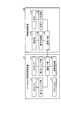
- FIG. 1 is a diagram illustrating an example of a system configuration of the information providing system according to the first embodiment.
- FIG. 2 is a block diagram illustrating a functional configuration of each device included in the information providing system according to the first embodiment.
- FIG. 3 is a diagram illustrating an example of 3D sensing.
- FIG. 4 is a diagram illustrating an example of 2D sensing.
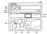
- FIG. 5 is a diagram illustrating an example of the on-site grasp screen.
- FIG. 6 is a diagram illustrating an example of the on-site grasp screen.
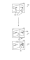
- FIG. 7 is a diagram illustrating an example of transition of a 3D image.
- FIG. 8 is a diagram illustrating an example of the transition of the projected image in the field.
- FIG. 9 is a diagram illustrating an example of the transition of the projected image in the field.
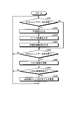
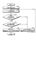
- FIG. 10 is a flowchart illustrating the procedure of the sensing process according to the first embodiment.
- FIG. 11 is a flowchart illustrating the procedure of the display control process according to the first embodiment.
- FIG. 12 is a flowchart illustrating the procedure of the information providing process according to the first embodiment.
- FIG. 13 is a diagram illustrating an application example of the 3D data acquisition method.
- FIG. 14 is a diagram illustrating a hardware configuration example of a computer that executes the information providing program according to the first embodiment and the second embodiment.
- FIG. 1 is a diagram illustrating an example of a system configuration of the information providing system according to the first embodiment.
- FIG. 1 shows an example in which equipment inspection work is carried out at a certain facility as an example of work.
- Sites 2A to 2N are illustrated as examples of sections in which inspection work is performed.
- the supporter 5 who supports the inspection work by the site worker 3 from the remote place 4 separated from the site 2A to 2N. The case where an inspection operation is performed is illustrated.
- the site 2A to the site 2N may be collectively referred to as “site 2”.
- the information providing system 1 shown in FIG. 1 provides an information providing service for providing support data useful for inspection work at the site 2 to the worker 3.
- the information provision system 1 performs three-dimensional measurement on a static object in the environment and two-dimensional measurement on the position of a dynamic object in the environment, and grasps the environment based on these measurement data.
- Support data generated in the remote place 4 is provided to the site 2 through the image. Therefore, as a result of generating the support data through the environment grasping image digitized including the position and action of the person in the environment of the site 2, it is possible to provide the support data suitable for the scene where the work is performed on the site 2.
- the information providing system 1 accommodates an information providing device 10 and an information processing device 100.
- the information providing apparatus 10 and the information processing apparatus 100 are illustrated one by one.
- a plurality of information processing apparatuses 100 may be provided for each information providing apparatus 10, and one information providing apparatus 10 may be provided.
- a plurality of information providing apparatuses 10 may be provided for each information processing apparatus 100.
- the information providing apparatus 10 and the information processing apparatus 100 are connected to each other via a predetermined network so that they can communicate with each other.
- a predetermined network any type of communication network such as the Internet (Internet), a LAN (Local Area Network), and a VPN (Virtual Private Network) can be adopted regardless of whether it is wired or wireless.
- Internet Internet
- LAN Local Area Network
- VPN Virtual Private Network
- both may be connected to each other by short-range wireless communication such as BLE (Bluetooth (registered trademark) Low Energy).
- BLE Bluetooth (registered trademark) Low Energy
- the information providing apparatus 10 is an apparatus that provides support data to the worker 3 at the site 2 in accordance with an instruction from the information processing apparatus 100.
- the information providing apparatus 10 is implemented as a portable apparatus in which the operator 3 performs hand carry.
- the operator 3 performs inspection work at the work sites 2A to 2N, it is not necessary to install one information providing device 10 per work site 2, and one information providing device 10 is installed at each work site. 2 can be used around. That is, whenever the inspection work is completed at the site 2, the operator 3 brings the information providing device 10 to the next site 2 by hand carry or the like, and places the information providing device 10 at an arbitrary position on the next site 2 to assist. You can receive data.
- the information providing apparatus 10 performs the above three-dimensional measurement and transmits the three-dimensional measurement data to the information processing apparatus 100 in the remote place 4 when the installation location of the information providing apparatus 10 is changed. Then, the information providing apparatus 10 repeatedly executes the above two-dimensional measurement until the installation location of the information providing apparatus 10 changes, and each time the two-dimensional measurement is performed, the information providing apparatus 10 receives the two-dimensional measurement data from the remote location 4 information processing apparatus. To 100. After transmitting these three-dimensional and two-dimensional measurement data, when the information providing apparatus 10 receives the above-described support data from the information processing apparatus 100 in the remote location 4, the information providing apparatus 10 performs the field 2 according to the support data presentation conditions received together with the support data. An image corresponding to the support data is projected at a predetermined position.
- the change in the installation location may be detected by providing a mechanical switch on the ground surface of the information providing apparatus 10 that is turned on when installed and turned off when carried. Moreover, it is good also as detecting by accepting the detachment
- the information processing apparatus 100 is a computer that generates the support data.
- the information processing apparatus 100 is implemented as a personal computer used by the supporter 5 at the remote place 4.
- the “remote location” mentioned here is not necessarily limited to a location where the distance to the site 2 is physically far, but also includes a location where it is difficult to share information with the site 2 to some extent.
- the information processing apparatus 100 when the information processing apparatus 100 receives three-dimensional and two-dimensional measurement data from the information providing apparatus 10, the information processing apparatus 100 corresponds to the two-dimensional measurement data on the three-dimensional image of the site 2 rendered from the three-dimensional measurement data.
- An on-site grasp screen in which the three-dimensional model of the worker 3 is superimposed on the position of the worker 3 is generated and displayed on a predetermined display unit. Thereafter, the information processing apparatus 100 updates the position of the three-dimensional model of the worker 3 on the on-site grasp screen every time two-dimensional measurement data is received from the information providing apparatus 10.
- the information processing apparatus 100 receives designation of a target on the site grasp screen, the information processing apparatus 100 generates support data related to the target and transmits the support data to the information providing apparatus 10.
- FIG. 2 is a block diagram illustrating a functional configuration of each device included in the information providing system 1 according to the first embodiment.
- the portable information providing apparatus 10 includes a 3D (three dimensions) sensor 11, a first sensing unit 12, a 2D (two dimensions) sensor 13, a second sensing unit 14, and a communication I. / F (interface) unit 15, projection control unit 16, and projector 17.
- the 3D sensor 11 is a three-dimensional scanner that outputs physical shape data of a space.
- the 3D sensor 11 can be implemented as a three-dimensional scanner including an IR (infrared) camera and an RGB camera. These IR camera and RGB camera have the same resolution, and share the three-dimensional coordinates of the point group handled on the computer.
- the RGB camera captures a color image in synchronization with capturing a distance image by measuring the time until the IR irradiation light is reflected back to the environment object and returns. Image.
- the distance (X, Y, Z) and the color information (R, G, B) are obtained for each pixel corresponding to the angle of view of the 3D sensor 11, that is, the point corresponding to the resolution in the three-dimensional space.
- the 3D sensor 11 has a resolution of vertical 480 pixels ⁇ horizontal 640 pixels.
- the first sensing unit 12 is a processing unit that senses a static object in the environment using the 3D sensor 11.
- the first sensing unit 12 activates 3D sensing when the power of the information providing apparatus 10 is switched from the OFF state to the ON state or when the installation location of the information providing apparatus 10 is changed. .
- FIG. 3 is a diagram illustrating an example of 3D sensing.
- the 3D sensor 11 by driving and controlling a motor (not shown), the 3D sensor 11 is pan-driven in the horizontal direction, that is, around the Z axis in the three-dimensional coordinate system shown in FIG. Assume that 3D sensing data is generated. Further, in FIG. 3, as an example of the angle of view that the 3D sensor 11 has, an angle of view “45 °” in the vertical direction and an angle of view “60 °” in the horizontal direction are indicated by reference numeral 20.
- the first sensing unit 12 acquires 3D data, that is, a distance image and a color image by causing the 3D sensor 11 to capture a distance image and a color image (S1). Subsequently, the first sensing unit 12 pan-drives the 3D sensor 11 around the Z axis over a predetermined angle, for example, 60 ° in the example of the angle of view in this example (S2). In addition, the first sensing unit 12 acquires 3D data with a new field of view after pan driving.
- 3D data that is, a distance image and a color image by causing the 3D sensor 11 to capture a distance image and a color image (S1).
- the first sensing unit 12 pan-drives the 3D sensor 11 around the Z axis over a predetermined angle, for example, 60 ° in the example of the angle of view in this example (S2).
- the first sensing unit 12 acquires 3D data with a new field of view after pan driving.
- the first sensing unit 12 obtains 3D data in all directions in the horizontal direction, that is, 360 ° by performing pan driving a predetermined number of times, for example, 5 times in the example of the angle of view in this example. Until then, pan driving and acquisition of 3D data are repeated. And if the 3D data of all the azimuth
- the coordinate system of the 3D sensing data adopts a three-dimensional coordinate system having the information providing apparatus 10 as an origin, but is not limited thereto.
- the origin of the three-dimensional coordinate system can be set at an arbitrary position, or can be converted into a global coordinate system from a correspondence relationship with global coordinates associated with an AR (Augmented Reality) marker.
- the 3D sensing data generated by the first sensing unit 12 is transmitted to the information processing apparatus 100 via the communication I / F unit 15.
- the communication I / F unit 15 As an example, from the viewpoint of suppressing the processing load of the information providing apparatus 10 and the traffic on the transmission path, a case is assumed in which 3D sensing data is transmitted once every time there is a change in the installation location of the information providing apparatus 10. . After transmission of such 3D sensing data, only the live image captured at a predetermined sampling frequency by the RGB camera of the 3D sensor 11 is transmitted to the information processing apparatus 100.
- the 2D sensor 13 is a sensor that measures a two-dimensional distance.
- the 2D sensor 13 may employ an LRF (Laser Range Finder), a millimeter wave radar, a laser radar, or the like.
- LRF Laser Range Finder
- the 2D sensor 13 is driven and controlled by a motor (not shown) and rotated in the horizontal direction, that is, around the Z axis, the distance on the horizontal plane, that is, the XY plane with the information providing device 10 as the origin can be acquired.
- a case is assumed in which distance measurement for acquiring distance information of 1000 points per rotation can be realized with a sampling frequency of 40 Hz.
- the second sensing unit 14 is a processing unit that senses the position of a dynamic object in the environment at the site 2.
- the second sensing unit 14 activates 2D sensing at the same time when 3D sensing is activated by the first sensing unit 12 or after 3D sensing is performed.
- the 2nd sensing part 14 repeatedly performs 2D sensing until the installation place of the information provision apparatus 10 changes.
- FIG. 4 is a diagram illustrating an example of 2D sensing.
- the second sensing unit 14 acquires 2D data, that is, two-dimensional distance information in all directions on the XY plane by rotating the 2D sensor 13 around the Z axis (S41). Thereafter, the second sensing unit 14 detects the presence or absence of a person based on whether or not the two-dimensional distance information acquired in S1 includes a distance locus corresponding to the shape of the person (S42).
- the second sensing unit 14 has a similarity having a similarity equal to or higher than a predetermined threshold with a predetermined template, for example, gender, age, or waist shape set for each waist direction with respect to the 2D sensor 13. It is possible to detect the presence or absence of a person by determining whether or not the plot 25 is present in 2D data.
- a time before the time when the 2D data is acquired for example, temporarily Noise may be removed from the presence or absence of a difference from 2D data before the time.
- the second sensing unit 14 is detected from the plot of the distance detected from the 2D data and the 2D data before the temporary time. It is determined whether or not there is a change in the centroid position 25a of the figure formed by the distance plot 25 on the XY plane and the contour of the plot 25 with respect to the distance plot. And the 2nd sensing part 14 is good also as detecting a person, narrowing down when any one or more changes among the gravity center position 25a and the outline of the plot 25.
- the 2D sensing data generated by the second sensing unit 14 is transmitted to the information processing apparatus 100 via the communication I / F unit 15.
- the second sensing unit 14 transmits the position information of the person, for example, the coordinate group of the plot 25 of the distance and the coordinates of the gravity center position 25a as 2D sensing data.
- the second sensing unit 14 transmits a notification that no person exists as 2D sensing data.
- the information processing apparatus 100 sets the 3 of the worker 3 to the position of the worker 3 corresponding to the 2D sensing data on the 3D image of the site 2 rendered from the 3D sensing data.
- the dimension model can be displayed in an overlapping manner (S43). Furthermore, by transmitting 2D sensing data each time 2D sensing is performed, the position of the 3D model of the worker 3 on the 3D image can be updated to the latest position.
- the communication I / F unit 15 is an interface that performs communication control with another device, such as the information processing device 100.
- a network interface card such as a LAN card can be adopted as the communication I / F unit 15.
- a communication module of BLE can be adopted for the communication I / F unit 15.
- the communication I / F unit 15 transmits 3D sensing data or 2D sensing data to the information processing apparatus 100, receives support data display instructions, support data presentation conditions, or the like from the information processing apparatus 100. To do.
- the projection control unit 16 is a processing unit that performs projection control on the projector 17.
- the projection control unit 16 when receiving the support data from the information processing apparatus 100 at the remote location 4, the projection control unit 16 images corresponding to the support data at a predetermined position on the site 2 according to the support data presentation conditions received together with the support data. Project.
- presentation conditions include the correspondence between the position of the image to be projected on the projector 17, for example, the representative point such as the vertex or the center of gravity of the image, and the display position of the three-dimensional coordinates, and the content of the image, for example, mark, text
- the timing at which the projector 17 projects an image for example, the designation of time is included.
- the projector 17 is a projector that projects an image in space.
- an arbitrary display method such as a liquid crystal method, a DLP (Digital Light Processing: registered trademark) method, a laser method, or the like can be adopted.
- the processing units such as the first sensing unit 12, the second sensing unit 14, and the projection control unit 16 can be mounted as follows. For example, it can be realized by causing a central processing unit, a so-called CPU (Central Processing Unit), or the like to develop and execute a process that exhibits the same function as each of the above processing units on a memory. These functional units are not necessarily executed by the central processing unit, and may be executed by an MPU (Micro Processing Unit). Each of the above functional units can be realized by hard wired logic such as ASIC (Application Specific Integrated Circuit) or FPGA (Field Programmable Gate Array).
- ASIC Application Specific Integrated Circuit
- FPGA Field Programmable Gate Array
- each processing unit can be implemented using various semiconductor memory elements such as RAM (Random Access Memory) and flash memory.
- the storage device referred to by each processing unit described above is not necessarily a main storage device, and may be an auxiliary storage device. In this case, HDD (Hard Disk Drive), optical disk, SSD (Solid State Drive), etc. can be adopted.
- the information processing apparatus 100 includes an input unit 110, a display unit 120, a communication I / F unit 130, a display control unit 140, and a support data generation unit 150.
- the information processing apparatus 100 may include a functional unit included in a known computer other than the functional units illustrated in FIG. 2, for example, various audio output devices and printing devices.
- the input unit 110 is an input device that receives instruction inputs for various types of information, for example, designation of targets on a 3D image.
- the information processing apparatus 100 when the information processing apparatus 100 is implemented as a stationary personal computer, a keyboard, a mouse, or the like can be employed. Such a mouse functions as a pointing device by cooperating with a display unit 120 described later.
- the case where the pointing device function is realized by a mouse will be described as an example, but the pointing device function may be realized by another input device such as a touch pad.
- the input unit 110 and the display unit 120 can be integrated as a touch panel.
- the display unit 120 is a display device that displays various types of information such as 3D images.
- the display unit 120 may be a liquid crystal display or an organic EL (electroluminescence) display that realizes display by light emission.
- the display unit 120 may also employ a projector that realizes display by projection.
- the communication I / F unit 130 is an interface that performs communication control with other devices, such as the information providing device 10.
- a network interface card such as a LAN card can be adopted as the communication I / F unit 130.
- a communication module of BLE can be adopted for the communication I / F unit 130.
- the communication I / F unit 130 receives 3D sensing data and 2D sensing data from the information providing apparatus 10, transmits a support data display instruction, support data presentation conditions, and the like to the information providing apparatus 10. To do.
- the display control unit 140 is a processing unit that performs display control on the display unit 120.
- the display control unit 140 generates an on-site grasp screen from 3D sensing data and 2D sensing data transmitted by the information providing apparatus 10. For example, when receiving 3D sensing data from the information providing apparatus 10, the display control unit 140 generates a 3D image by rendering the 3D sensing data. Further, the display control unit 140 generates a panoramic image by connecting the images of the entire field of view included in the 3D sensing data in the horizontal direction. Then, the display control unit 140 generates an on-site grasp screen including the 3D image and the panoramic image, and causes the display unit 120 to display the screen.
- the display control unit 140 displays the 3D model of the worker 3 at the position of the worker 3 corresponding to the 2D sensing data on the 3D image of the on-site grasp screen. Overlapping display. Thereafter, every time 2D sensing data is received, the display control unit 140 can update the position of the 3D model of the worker 3 on the 3D image of the on-site grasp screen to the latest position.
- the on-site grasp screen includes a color image captured at a predetermined sampling frequency by the RGB camera of the 3D sensor 11 from the viewpoint of the 3D image displayed on the display unit 120 as a live image. You can also.
- the on-site grasp screen 200 includes a 3D image 210, a panoramic image 220, a live image 230, and the like. Further, the site grasp screen 200 includes GUI components such as radio buttons 240, 250, 250A and 250B and a text box 250C. As described above, the display position of the 3D model 300 of the worker 3 displayed on the 3D image 210 of the on-site grasp screen 200 is updated every time 2D sensing data is received.
- a viewpoint for rendering the 3D image 210 is received by receiving a predetermined operation via the input unit 110 at an arbitrary point on the 3D image 210. Can be changed. Further, by accepting an operation for changing the direction of the direction designation pointer 270 on the 3D image 210 via the input unit 110, the viewpoint of the color image captured by the RGB camera of the 3D sensor 11 can also be changed. In conjunction with this, the viewpoint of the live image 230 is changed to the direction corresponding to the direction designation pointer 270.
- the slide operation of the slider 220A is accepted on the panoramic image 220, and the viewpoint of the RGB camera of the 3D sensor 11 is changed to a position where the area in the slider 220A falls within the angle of view of the RGB camera of the 3D sensor 11.
- the viewpoint of the image 230 can also be changed. Note that as an example of an operation via the input unit 110, a drag and drop operation with a pointing device, a flick operation with respect to a touch panel, and the like can be accepted.
- the radio button 250B when an arbitrary point on the 3D image 210 is designated via the input unit 110, the three-dimensional coordinates of the site 2 corresponding to the point that has accepted the designation are used as a reference. Thus, it is possible to accept an instruction to project content such as the message “Open!” Entered in the text box 250C as support data.
- a range designation can also be accepted.
- a message is illustrated as an example of the content, but an instruction to project other content such as a still image or a moving image can be received.
- the support data generation unit 150 is a processing unit that generates support data.
- the support data generation unit 150 when the support data generation unit 150 receives designation of a position related to a target for projecting support data on the 3D image, the position information of the person on the 3D image and the position where the designation is received Support data is generated according to the positional relationship.
- the support data generation unit 150 estimates the orientation of the worker 3 from the locus of the location information of the worker 3 transmitted from the information providing apparatus 10. For example, the support data generation unit 150 plots the position information of the worker 3 transmitted from the information providing apparatus 10 on the XY plane in time series, and calculates the latest worker 3 from the position information of the worker 3 before a predetermined time. The approximate straight line of the plot to the position information of is obtained. Then, the support data generation unit 150 estimates the traveling direction of the approximate straight line toward the latest position information of the worker 3 as the direction (front) of the worker 3, that is, the posture.
- the support data generation unit 150 estimates the orientation of the worker 3 from the locus of the position information is exemplified, but when a person is detected by the second sensing unit 14, the distance is plotted from the shape of the plot.
- the direction of the worker 3 may be estimated and transmitted as 2D sensing data.
- the support data generation unit 150 determines whether or not the target position for which the designation has been received is within a predetermined angle, for example, ⁇ ⁇ from the direction of the worker 3. At this time, if the position of the target is not within a predetermined angle from the direction of the worker 3, there is a possibility that the target that the supporter 5 tries to call attention to the worker 3 is not in the field of view of the worker 3. In this case, the support data generation unit 150 sets the position of the three-dimensional coordinate in front of the worker 3 among the three-dimensional coordinates included in the 3D sensing data as the projection position of the work site 2 as a presentation condition, and displays a guidance mark For example, the information providing apparatus 10 is instructed to project an arrow as support information.
- a predetermined angle for example, ⁇ ⁇ from the direction of the worker 3.
- the projection position has a predetermined height, for example, along with the X coordinate and the Y coordinate of the intersection that intersects the approximate straight line corresponding to the direction of the operator 3 on the XY plane among the three-dimensional coordinates included in the 3D sensing data.
- a Z coordinate having a height corresponding to the waist, chest and head of the operator 3 can be determined.
- the support data generation unit 150 further determines whether or not the distance between the worker 3 and the target on the XY plane is within a predetermined distance, for example, 1 m or 3 m.
- the support data generation unit 150 sets the position of the three-dimensional coordinate in front of the worker 3 among the three-dimensional coordinates included in the 3D sensing data as the projection position of the work site 2 as a presentation condition, and displays a guidance mark For example, the information providing apparatus 10 is instructed to project an arrow as support information.
- the support data generation unit 150 sets the target position for which the designation is accepted among the three-dimensional coordinates included in the 3D sensing data as the projection position of the work site 2 as the presentation condition, and sets the warning mark or content
- the information providing apparatus 10 is instructed to project at least one of them as support information.
- the processing units such as the display control unit 140 and the support data generation unit 150 can be mounted as follows. For example, it can be realized by causing a central processing unit, a so-called CPU, or the like to develop and execute a process that exhibits the same function as each of the above processing units on a memory. These functional units are not necessarily executed by the central processing unit, but may be executed by the MPU. Each functional unit described above can also be realized by a hard-wired logic such as ASIC or FPGA.
- each processing unit various semiconductor memory elements such as a RAM and a flash memory can be adopted as an example.
- the storage device referred to by each processing unit described above is not necessarily a main storage device, and may be an auxiliary storage device. In this case, an HDD, an optical disk, an SSD, or the like can be employed.
- FIG. 7 is a diagram illustrating an example of transition of a 3D image.
- FIG. 8 is a diagram illustrating an example of the transition of the projected image at the site 2. 7 and 8 show an example in which the valve 210A is designated as a target for projecting support data onto the work site 2.
- FIG. 7 and 8 show an example in which the valve 210A is designated as a target for projecting support data onto the work site 2.
- the support data is projected at the site 2 as shown in FIG. (S20).
- designation of a position related to the valve 210A is received as a target for projecting support data onto the site 2 on the 3D image 210 (S11)
- projection of support data is started at the site 2. That is, since the valve 210A does not exist within a predetermined angle from the front of the worker 3 at the stage where the designation of the position related to the valve 210A is received, the arrow 410 for guiding the worker 3 to the valve 210A is used as support data for the worker. 3 is projected on the front of S3 (S21).
- the process proceeds to S22, in which the operator 3 approaches the valve 210A than in the stage of S21.
- the valve 210A is present within a predetermined angle from the front of the worker 3, but the distance between the worker 3 and the valve 210A is not within the predetermined distance, so that the arrow 420 continues to guide the worker 3 to the valve 210A. Is projected on the front of the worker 3 as support data (S22). Then, the process proceeds to S23, in which the operator 3 gets closer to the valve 210A than in the step S22.
- a warning mark 430 is provided on the valve 210A.
- the content of the support data varies depending on the position of the worker 3. That is, the guidance mark is projected until the worker 3 approaches the position where the target can be easily recognized, while the warning mark is projected on the target when the worker 3 approaches the position where the worker 3 can easily recognize the target. Is done. For this reason, support data can be projected on the site 2 through the environment grasping screen digitized including the position and action of the person in the environment of the site 2. Therefore, it is possible to provide support data suitable for the scene where work is performed at the site 2.
- the information providing apparatus 10 is implemented as a portable device that allows the operator 3 to carry between the site 2 and the site 2, and when the operator 3 arrives at the site 2 where the inspection work is performed, the site 2 is provided. Can be placed in any location. For this reason, it is possible to cause the operator 3 to perform a hands-free inspection operation at the site 2.
- the 3D sensor 11 included in the information providing apparatus 10 is placed at an arbitrary place on the site 2, it may not be installed on the head of the worker 3 or the like. Therefore, the live image relayed from the site 2 can be prevented from being shaken by the movement of the worker 3, for example, the movement or body movement of the work, so that the work situation of the site 2 is shared between the worker 3 and the supporter 5. You can increase the level you can. In addition, the equipment that the operator 3 equips during the inspection work can be reduced.
- FIG. 9 is a diagram illustrating an example of the transition of the projected image at the site 2.
- FIG. 9 shows a case where a target for projecting support data on the work site 2 is designated as a region 500. Furthermore, FIG. 9 illustrates a case where the target is set in advance before the site grasp screen 200 is generated and received via the input unit 110.
- the information providing apparatus 10 is installed at the site 2
- support data is not projected at the site 2 (S30).
- the center of gravity of the region 500 does not exist within a predetermined angle from the front of the worker 3, and therefore the arrow 510 for guiding the worker 3 to the region 500 is assistance data.
- a target may be set in advance, or an area may be set instead of a point as a position related to the target. Also in this case, it is possible to provide support data suitable for a scene where work is performed on the site 2. Furthermore, the level at which the work situation of the site 2 can be shared between the worker 3 and the supporter 5 can be increased, and the equipment that the worker 3 equips during the inspection work can be reduced.
- FIG. 10 is a flowchart illustrating the procedure of the sensing process according to the first embodiment. This process is activated when the power supply of the information providing apparatus 10 is switched from the OFF state to the ON state or when the installation location of the information providing apparatus 10 is changed. Note that the processing illustrated in FIG. 10 is repeatedly executed until the power of the information providing apparatus 10 is switched to the OFF state.
- the first sensing unit 12 acquires 3D data, that is, a distance image and a color image by causing the 3D sensor 11 to capture a distance image and a color image (step S101). Subsequently, the first sensing unit 12 pan-drives the 3D sensor 11 around the Z axis over a predetermined angle, for example, 60 ° in the example of the angle of view in this example (step S102).
- the first sensing unit 12 repeatedly executes the processes of step S101 and step S102 until the number of times the pan driving is performed reaches a predetermined number, for example, 5 times (No in step S103).
- step S103 Yes when the number of times the pan driving is performed becomes a predetermined number (step S103 Yes), the first sensing unit 12 integrates the 3D data 3 acquired in all horizontal directions to perform 3D sensing. Data is generated (step S104). Then, the first sensing unit 12 transmits the 3D sensing data generated in step S104 to the information processing apparatus 100 (step S105).
- step S105 the second sensing unit 14 activates 2D sensing (step S106). Subsequently, the second sensing unit 14 rotates the 2D sensor 13 around the Z axis to acquire 2D data, that is, two-dimensional distance information in all directions on the XY plane (step S107).
- the second sensing unit 14 detects the presence or absence of a person based on whether or not the two-dimensional distance information acquired in step S107 includes a distance locus corresponding to the shape of the person (step S108).
- the second sensing unit 14 adds the position information of the person detected at Step S108 (Step S110), and the color captured by the RGB camera of the 3D sensor 11 2D sensing data including the image is transmitted to the information processing apparatus 100 (step S111).
- the second sensing unit 14 transmits only the color image captured by the RGB camera of the 3D sensor 11 to the information processing apparatus 100 as 2D sensing data (Step S111). . In this case as well, a notification that no person has been detected can be included in the 2D sensing data.
- step S111 is repeatedly executed until the setting location of the information providing apparatus 10 is changed (No in step S112). If there is a change in the setting location of the information providing apparatus 10 (step S112 Yes), the process returns to the above step S101, and the processes after step S101 are repeatedly executed as described above.
- FIG. 11 is a flowchart illustrating the procedure of display control processing according to the first embodiment. This process is a process that is repeatedly executed as long as communication with the information providing apparatus 10 is established.
- step S201 Yes when 3D sensing data is received from the information providing apparatus 10 (step S201 Yes), the display control unit 140 generates a 3D image by rendering the 3D sensing data (step S202). In addition, when 3D sensing data is not received (step S201 No), it transfers to the process of step S205.
- the display control unit 140 generates a panoramic image by connecting the images of the entire field of view included in the 3D sensing data in the horizontal direction (step S203). Then, the display control unit 140 generates an on-site grasp screen including the 3D image and the panoramic image, and displays the screen on the display unit 120 (step S204).
- step S205 when 2D sensing data is received from the information providing apparatus 10 (step S205 Yes), the display control unit 140 displays the color image included in the 2D sensing data received in step S205 as a live image on the site grasp screen (step S205). Step S206).
- step S207 When the position information of the person is included in the 2D sensing data (Yes in step S207), the display control unit 140 displays the position of the worker 3 on the position of the worker 3 corresponding to the 2D sensing data on the 3D image on the site grasp screen.
- the three-dimensional model is overlaid and displayed (step S208). Thereafter, the display control unit 140 returns to the process of step S201 and repeatedly executes the subsequent processes.
- FIG. 12 is a flowchart illustrating the information provision processing procedure according to the first embodiment. This process is activated when designation of a position related to a target for projecting support data on a 3D image is received.
- the support data generation unit 150 receives the position information of the worker 3 transmitted from the information providing apparatus 10.
- the direction of the worker 3 is estimated from the trajectory (step S302).
- the support data generation unit 150 determines whether or not the target position that has been designated in step S301 is within a predetermined angle from the orientation of the worker 3 (step S303). At this time, if the position of the target is not within a predetermined angle from the direction of the worker 3 (No in step S303), there is a possibility that the target that the supporter 5 tries to call attention to the worker 3 is not in the field of view of the worker 3. There is sex.
- the support data generation unit 150 sets the position of the three-dimensional coordinate in front of the worker 3 among the three-dimensional coordinates included in the 3D sensing data as the projection position of the work site 2 as a presentation condition, and displays a guidance mark
- the information providing apparatus 10 is instructed to project an arrow as support information (step S304).
- the information providing apparatus 10 projects a guidance mark on the front surface of the worker 3. Thereafter, the process returns to step S302.
- the support data generation unit 150 further determines whether or not the distance between the worker 3 and the target on the XY plane is within a predetermined distance (step S305).
- the support data generation unit 150 sets the position of the three-dimensional coordinate in front of the worker 3 among the three-dimensional coordinates included in the 3D sensing data as the projection position of the work site 2 as a presentation condition, and displays a guidance mark
- the information providing apparatus 10 is instructed to project an arrow as support information (step S304).
- the information providing apparatus 10 projects a guidance mark on the front surface of the worker 3. Thereafter, the process returns to step S302.
- the support data generation unit 150 sets the target position for which the designation is accepted among the three-dimensional coordinates included in the 3D sensing data as the projection position of the work site 2 as the presentation condition, and sets the warning mark or content
- the information providing apparatus 10 is instructed to project at least one of them as support information (step S306), and the process ends. As a result, the information providing apparatus 10 projects a guidance mark on the front surface of the worker 3.
- the information providing system 1 performs three-dimensional measurement related to the static object in the environment and two-dimensional measurement related to the position of the dynamic object in the environment.
- the support data generated at the remote place 4 is provided to the site 2 through the environment grasping image based thereon. Therefore, according to the information providing system 1 according to the present embodiment, it is possible to provide support data suitable for a scene where work is performed on the site 2.
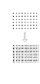
- 3D data acquisition method In the first embodiment, the case where the 3D sensor 11 is controlled to acquire 3D data having a resolution of 480 pixels in the vertical direction and 640 pixels in the horizontal direction is exemplified. A high resolution is obtained by further acquiring 3D data after shifting by half the pitch between pixels, that is, half pitch, and interpolating the data of the gap portion between pixels between each 3D data. 3D data can also be generated.
- FIG. 13 is a diagram showing an application example of the 3D data acquisition method.
- a part of a point group on a space forming a pixel of 480 vertical pixels ⁇ 640 horizontal pixels is indicated by a black circle.
- FIG. 13 shows the 3D data acquired when the 3D sensor 11 is driven over the half pitch of the pixel in the right direction as compared with the case where 3D data is acquired with the point group indicated by the black circle.
- Part of the point cloud is shown as a filled point.
- FIG. 13 shows the 3D data acquired when the 3D sensor 11 is driven over a half pitch of the pixel in the downward direction as compared with the case where 3D data is acquired with a point group indicated by a black circle.
- FIG. 13 shows the case where the 3D sensor 11 is driven over a half pitch of the pixel in the right and down directions compared to the case where 3D data is acquired with a point group indicated by a black circle.
- a part of the point group of the 3D data to be processed is shown by white fill.
- the identification information is recognized by image processing from the AR marker provided in the vicinity of the inspection location on the site 2, and information associated with the identification information, for example, an inspection procedure or precautions is acquired by searching the database. Information acquired by the search can be projected as support data.
- a skilled worker or a predecessor performs field work in advance, records a video of the procedure, acquires a hand image from the viewpoint of the skilled worker, and projects the image of the skilled worker from the viewpoint of the worker. Thereby, the worker 3 can carry out the work while following the movement of the hands of the skilled worker.
- a wearable gadget worn by the worker 3 may be included.
- a gadget equipped with a motion sensor such as an acceleration sensor or a gyro sensor can be attached to the wrist or finger of the worker 3.
- the information providing apparatus 10 or the information processing apparatus 100 recognizes a gesture from the sensor value obtained by the motion sensor of the gadget, for example, a gesture for moving the gadget from the left direction to the right direction, and the support data associated with the gesture. For example, an operation for turning on or off the projection of support data, a page feed or page return of support data over a plurality of pages, or the like can be executed.
- gesture recognition not only operations related to the display contents of support data, but also operations for specifying the projection position of support data can be accepted by gesture recognition.
- gesture recognition it is not limited to gesture recognition, and by sensing the light emission position of a LED (Light Emitting Diode) built in or attached to a laser pointer or gadget from a live image, an operator among the three-dimensional coordinates included in the 3D sensing data.
- the support data can also be displayed at the coordinates of the intersection of the three trunks, for example, the straight line connecting the light emission position from the center of gravity position.
- trajectory can also be projected on the environment of the field 2 while acquiring the locus
- the position information of the tag can be acquired and managed.
- the position information of the environmental item can be managed by the operator attaching the tag to the environmental side. For example, a tag is pasted on a defective part, and the position and inspection time are managed. It can also be used for management such as an alarm sounding when an administrator puts a tag “no entry” on the doorknob at the site and then a person other than the administrator touches the doorknob.
- [Supporting data generator] In the first embodiment, the case where the generation of support data is executed by the information processing apparatus 100 is illustrated. However, when designation of a position related to a predetermined target is accepted on the environment grasp image, the designation is accepted.
- the information providing apparatus 10 may generate the above-described support data after transmitting the target position and the position of the dynamic object on the 3D image from the information processing apparatus 100 to the information providing apparatus 10. .
- each component of each illustrated apparatus does not necessarily need to be physically configured as illustrated.
- the specific form of distribution / integration of each device is not limited to that shown in the figure, and all or a part thereof may be functionally or physically distributed or arbitrarily distributed in arbitrary units according to various loads or usage conditions. Can be integrated and configured.
- the display control unit 140 and the support data generation unit 150 are mounted on the information processing apparatus 100 used by the supporter 5 is illustrated, but these function units are mounted on an external server device or the like, and the information processing apparatus In 100, only the input / output of information can be executed.
- FIG. 14 is a diagram illustrating a hardware configuration example of a computer that executes the information providing program according to the first embodiment and the second embodiment.
- the computer 1100 includes an operation unit 1110a, a speaker 1110b, a camera 1110c, a display 1120, and a communication unit 1130.
- the computer 1100 further includes a CPU 1150, a ROM 1160, an HDD 1170, and a RAM 1180. These units 1110 to 1180 are connected via a bus 1140.
- the HDD 1170 stores an information providing program 1170 a that exhibits the same functions as those of the first sensing unit 12, the second sensing unit 14, and the projection control unit 16 described in the first embodiment.
- This information providing program 1170a may be integrated or separated as with the respective components of the first sensing unit 12, the second sensing unit 14, and the projection control unit 16 shown in FIG. That is, the HDD 1170 does not necessarily store all the data shown in the first embodiment, and data used for processing may be stored in the HDD 1170.
- the CPU 1150 reads the information providing program 1170a from the HDD 1170 and develops it in the RAM 1180.
- the information providing program 1170a functions as an information providing process 1180a as shown in FIG.
- the information providing process 1180a expands various data read from the HDD 1170 in an area allocated to the information providing process 1180a in the storage area of the RAM 1180, and executes various processes using the expanded various data.
- the processing shown in FIG. 10 and part of the processing shown in FIG. 12 are included.
- the CPU 1150 does not necessarily operate all the processing units described in the first embodiment, and it is only necessary to virtually realize the processing unit corresponding to the process to be executed.
- each program is stored in a “portable physical medium” such as a flexible disk inserted into the computer 1100, so-called FD, CD-ROM, DVD disk, magneto-optical disk, IC card or the like.
- the computer 1100 may acquire and execute each program from these portable physical media.
- Each program is stored in another computer or server device connected to the computer 1100 via a public line, the Internet, a LAN, a WAN, or the like, and the computer 1100 acquires and executes each program from these. It may be.
Landscapes
- Engineering & Computer Science (AREA)
- Physics & Mathematics (AREA)
- General Physics & Mathematics (AREA)
- Multimedia (AREA)
- Signal Processing (AREA)
- Theoretical Computer Science (AREA)
- General Engineering & Computer Science (AREA)
- Optics & Photonics (AREA)
- Computer Hardware Design (AREA)
- Human Computer Interaction (AREA)
- User Interface Of Digital Computer (AREA)
- Length Measuring Devices By Optical Means (AREA)
- Closed-Circuit Television Systems (AREA)
Abstract
情報提供装置(10)は、3次元で環境の静的な対象物を計測し、環境の動的な対象物の位置を逐次計測し、計測した静的な対象物の計測データを通信網を介して情報処理装置(100)に送信し、計測した動的な対象物の計測データを通信網を介して情報処理装置(100)に送信し、情報処理装置(100)で静的な対象物の計測データと動的な対象物の計測データより生成した環境把握画像に基づいて情報処理装置(100)から支援データを受信し、受信した支援データを所定のタイミングで環境に提示する。
Description
本発明は、情報提供方法、情報提供プログラム、情報提供装置、情報処理装置及び情報提供システムに関する。
施設の保守、施工、医療などの各種の現場における作業を支援する技術の一例として、映像表示装置や作業支援用情報提示装置が提案されている。
例えば、映像表示装置は、カメラから得られた映像及び位置姿勢計測装置の計測データを用いて携帯型計算機の位置及び姿勢を算出する位置姿勢計測部を有する。さらに、映像表示装置は、位置姿勢計側部から得られた情報及びカメラから得られた映像を基に、投影すべき映像に関する映像情報と対象物の配置及び形状とを投影情報データベース及び対象物配置、形状データベースから検索する投影情報検索部を有する。さらに、映像表示装置は、映像投影装置と対象物の相対的位置関係と対象物の形状とに基づいて、検索した映像情報から投影する映像を生成する映像情報生成部とを有する。
また、作業支援用情報提示装置は、プロジェクタで投影された投影画像中の特定の対象物をレーザポインタ等で指し示すことによって、その対象物に関連付けられている処理を実行するものである。この作業支援用情報提示装置は、カメラが撮影した投影画像を送受信する画像送受信手段と、カメラ画像を表示する表示手段とを有する。さらに、作業支援用情報提示装置は、表示されたカメラ画像上でプロジェクタ投影対象物の表示位置と表示属性と該投影対象物に関連付けられる処理内容とを関連付けて蓄積する情報蓄積手段を有する。さらに、作業支援用情報提示装置は、蓄積された投影対象物の表示のオン・オフおよびそれに関連付けられた処理内容の実行のオン・オフを指示入力するデータ入力手段を有する。さらに、作業支援用情報提示装置は、入力された指示情報に応じて投影対象物の表示や処理実行のオン・オフを制御する表示・処理制御手段を有する。
しかしながら、上記の技術は、いずれも現場における人の位置や行動が盲点となるので、現場で作業が行われる場面に相応しい支援データが提供できない場合がある。
すなわち、上記の映像表示装置及び上記の作業支援用情報提示装置では、いずれもカメラにより撮像された画像を通じて、投影がなされる映像を生成したり、あるいは投影の内容を取捨選択したりする。ところが、カメラにより撮像される画像は、あくまでカメラの視点から撮像されるものであるので、人の位置や行動と一致するとは限らない。このため、カメラにより撮像される画像には、必ずしも作業状況が映っているとは限らない。このようにカメラにより撮像される画像に作業状況が映っていない場合、実際の作業状況とは見当違いの位置に投影が行われたり、見当違いの内容が投影されたりすることもある。
1つの側面では、本発明は、現場で作業が行われる場面に相応しい支援データを提供できる情報提供方法、情報提供プログラム、情報提供装置、情報処理装置及び情報提供システムを提供することを目的とする。
一態様の情報提供方法は、情報提供装置が実行する情報提供方法であって、3次元で環境の静的な対象物を計測し、環境の動的な対象物の位置を逐次計測し、計測した静的な対象物の計測データを通信網を介して所定の情報処理装置に送信し、計測した動的な対象物の計測データを通信網を介して前記情報処理装置に送信し、前記情報処理装置で静的な対象物の計測データと動的な対象物の計測データより生成した環境把握画像に基づいて前記情報処理装置から支援データを受信し、受信した支援データを所定のタイミングで環境に提示する処理を実行する。
現場で作業が行われる場面に相応しい支援データを提供できる。
以下に添付図面を参照して本願に係る情報提供方法、情報提供プログラム、情報提供装置、情報処理装置及び情報提供システムについて説明する。なお、この実施例は開示の技術を限定するものではない。そして、各実施例は、処理内容を矛盾させない範囲で適宜組み合わせることが可能である。
[システム構成]
図1は、実施例1に係る情報提供システムのシステム構成の一例を示す図である。図1には、作業の一例として、ある施設で設備の点検作業が実施される例が示されており、点検作業が行われる区画の一例として、現場2A~現場2Nが例示されている。さらに、図1には、現場2A~現場2Nで点検作業を行う作業者3に加え、現場2A~現場2Nと隔てられた遠隔地4から現場作業者3による点検作業を支援する支援者5により点検作業が実施される場合が例示されている。なお、以下では、現場2A~現場2Nを総称する場合に「現場2」と記載する場合がある。
図1は、実施例1に係る情報提供システムのシステム構成の一例を示す図である。図1には、作業の一例として、ある施設で設備の点検作業が実施される例が示されており、点検作業が行われる区画の一例として、現場2A~現場2Nが例示されている。さらに、図1には、現場2A~現場2Nで点検作業を行う作業者3に加え、現場2A~現場2Nと隔てられた遠隔地4から現場作業者3による点検作業を支援する支援者5により点検作業が実施される場合が例示されている。なお、以下では、現場2A~現場2Nを総称する場合に「現場2」と記載する場合がある。
図1に示す情報提供システム1は、現場2における点検作業に役立つ支援データを作業者3へ提供する情報提供サービスを提供するものである。かかる情報提供サービスの一環として、情報提供システム1は、環境の静的な対象物に関する3次元計測及び環境の動的な対象物の位置に関する2次元計測を行い、これらの計測データに基づく環境把握画像を通じて遠隔地4で生成された支援データを現場2に提供する。もって、現場2の環境に人の位置や行動を含めてデジタイズされた環境把握画像を通じて支援データが生成される結果、現場2で作業が行われる場面に相応しい支援データを提供できる。
図1に示すように、情報提供システム1には、情報提供装置10と、情報処理装置100とが収容される。なお、ここでは、一例として、情報提供装置10及び情報処理装置100を1台ずつ例示したが、1台の情報提供装置10につき複数台の情報処理装置100を設けることとしてもよいし、1台の情報処理装置100につき複数台の情報提供装置10を設けることとしてもよい。
これら情報提供装置10及び情報処理装置100は、所定のネットワークを介して、互いが通信可能に接続される。かかるネットワークの一例としては、有線または無線を問わず、インターネット(Internet)、LAN(Local Area Network)やVPN(Virtual Private Network)などの任意の種類の通信網を採用できる。この他、BLE(Bluetooth(登録商標) Low Energy)等の近距離無線通信によって両者が通信接続されることとしてもかまわない。
情報提供装置10は、現場2の作業者3に対し、情報処理装置100からの指示にしたがって支援データを提供する装置である。
一実施形態として、情報提供装置10は、作業者3がハンドキャリーを行うポータブル型の装置として実装される。例えば、作業者3が現場2A~現場2Nで点検作業を行うとしたとき、1つの現場2につき1台の情報提供装置10を設置せずともかまわず、1台の情報提供装置10を各現場2で持ち回って使用することができる。すなわち、作業者3は、現場2で点検作業が終了する度に、次の現場2へハンドキャリー等で情報提供装置10を持ち込み、次の現場2の任意の位置に載置することにより、支援データの提供を受けることができる。
一例として、情報提供装置10は、情報提供装置10の設置場所に変化があった場合に上記の3次元計測を実行して3次元の計測データを遠隔地4の情報処理装置100へ送信する。そして、情報提供装置10は、情報提供装置10の設置場所が変わるまで上記の2次元計測を繰り返し実行し、2次元計測が実行される度に2次元の計測データを遠隔地4の情報処理装置100へ送信する。これら3次元及び2次元の計測データの送信後に、情報提供装置10は、遠隔地4の情報処理装置100から上記の支援データを受信すると、支援データと共に受信した支援データの提示条件にしたがって現場2の所定位置に支援データに対応する画像を投影する。
なお、上記の設置場所の変化は、情報提供装置10の接地面に設置時にON状態になり、携帯時にOFF状態となるメカスイッチを設けることにより検知することとしてもよい。また、作業者3が携帯する携帯端末装置上で動作する点検作業管理用のアプリケーションプログラムが提供するGUIを通じて、現場2からの離脱及び現場2への到着を受け付けることにより検知を行うこととしてもよい。また、情報提供装置10が接続する無線LANのアクセスポイントなどが切り替わったか否かにより検知を行うこととしていもよいし、GPS受信機により測定される位置情報に変化があるか否かにより検知を行うこととしてもよい。
情報処理装置100は、上記の支援データを生成するコンピュータである。
一実施形態として、情報処理装置100は、遠隔地4で支援者5が使用するパーソナルコンピュータとして実装される。ここで言う「遠隔地」とは、必ずしも現場2との距離が物理的に遠い場所に限定されず、現場2との間で対面の情報共有が困難である程度に隔てられた場所も含まれる。
例えば、情報処理装置100は、情報提供装置10から3次元及び2次元の計測データを受信すると、3次元の計測データからレンダリングされる現場2の3次元画像上の2次元の計測データに対応する作業者3の位置に作業者3の3次元モデルが重畳された現場把握画面を生成して所定の表示部に表示させる。その後、情報処理装置100は、情報提供装置10から2次元の計測データを受信する度に、現場把握画面における作業者3の3次元モデルの位置を更新する。そして、情報処理装置100は、現場把握画面上で目標の指定を受け付けた場合に、当該目標に関する支援データを生成してその支援データを情報提供装置10へ送信する。
[ポータブル型の情報提供装置10]
図2は、実施例1に係る情報提供システム1に含まれる各装置の機能的構成を示すブロック図である。図2に示すように、ポータブル型の情報提供装置10は、3D(three dimensions)センサ11と、第1センシング部12と、2D(two dimensions)センサ13と、第2センシング部14と、通信I/F(interface)部15と、投影制御部16と、プロジェクタ17とを有する。
図2は、実施例1に係る情報提供システム1に含まれる各装置の機能的構成を示すブロック図である。図2に示すように、ポータブル型の情報提供装置10は、3D(three dimensions)センサ11と、第1センシング部12と、2D(two dimensions)センサ13と、第2センシング部14と、通信I/F(interface)部15と、投影制御部16と、プロジェクタ17とを有する。
3Dセンサ11は、空間の物理的な形状データを出力する3次元スキャナである。
一実施形態として、3Dセンサ11は、IR(infrared)カメラとRGBカメラとを含む3次元スキャナとして実装できる。これらIRカメラ及びRGBカメラは、同一の解像度を有し、コンピュータ上で扱う点群の3次元座標も共有される。例えば、3Dセンサ11では、IRカメラが赤外線の照射光が環境の対象物に反射して戻ってくるまでの時間を計測することにより距離画像を撮像するのに同期して、RGBカメラがカラー画像を撮像する。これによって、3Dセンサ11の画角に対応する画素、すなわち3次元空間上の解像度に対応する点ごとに距離(X,Y,Z)及び色情報(R,G,B)が得られる。なお、以下では、あくまで一例として、3Dセンサ11が縦480ピクセル×横640ピクセルの解像度を有する場合を想定する。
第1センシング部12は、3Dセンサ11を用いて環境の静的な対象物をセンシングする処理部である。
一実施形態として、第1センシング部12は、情報提供装置10の電源がOFF状態からON状態に切り替えられた場合や情報提供装置10の設置場所に変化があった場合に、3Dセンシングを起動する。
図3は、3Dセンシングの一例を示す図である。図3には、図示しないモータを駆動制御して、3Dセンサ11を水平方向、すなわち図1に示した3次元座標系におけるZ軸回りでパン駆動させることにより、水平方向で360°の視野を持つ3Dのセンシングデータが生成される場合を想定する。さらに、図3には、3Dセンサ11が有する画角の一例として、上下方向の画角「45°」及び左右方向の画角「60°」が符号20として示されている。
例えば、3Dセンシングが起動されると、第1センシング部12は、3Dセンサ11に距離画像及びカラー画像を撮像させることにより3Dデータ、すなわち距離画像及びカラー画像を取得する(S1)。続いて、第1センシング部12は、所定の角度、例えば本例の画角の例で言えば60°にわたって3Dセンサ11をZ軸回りにパン駆動させる(S2)。その上で、第1センシング部12は、パン駆動後の新たな視野で3Dデータを取得する。その後、第1センシング部12は、所定の回数、例えば本例の画角の例で言えば5回にわたってパン駆動が行われることにより水平方向の全方位、すなわち360°の3Dデータが取得されるまで、パン駆動及び3Dデータの取得を繰り返し実行する。そして、第1センシング部12は、水平方向の全方位の3Dデータが取得されると、6回にわたって取得された3Dデータを統合することにより、3Dのセンシングデータ、いわゆるポイントクラウド(X,Y,Z,R,G,B)を生成する(S3)。なお、3Dのセンシングデータの座標系には、一例として、情報提供装置10を原点とする3次元座標系が採用されることとするが、これに限定されない。例えば、3次元座標系の原点は、任意の位置とすることができるし、AR(Augmented Reality)マーカに対応付けられたグローバル座標との対応関係からグローバル座標系に変換することもできる。
このように第1センシング部12により生成された3Dのセンシングデータは、通信I/F部15を介して情報処理装置100へ送信される。ここでは、一例として、情報提供装置10の処理負荷及び伝送路のトラフィックを抑制する観点から、情報提供装置10の設置場所に変化がある度に3Dのセンシングデータを1度送信する場合を想定する。かかる3Dのセンシングデータの送信後は、3Dセンサ11のRGBカメラにより所定のサンプリング周波数で撮像されるライブ画像だけが情報処理装置100に送信されることとする。
2Dセンサ13は、2次元の距離を測定するセンサである。
一実施形態として、2Dセンサ13には、LRF(Laser Range Finder)を始め、ミリ波レーダやレーザレーダなどを採用できる。例えば、2Dセンサ13を図示しないモータを駆動制御して水平方向、すなわちZ軸回りに回転させることにより、情報提供装置10を原点とする水平面、すなわちXY平面上の距離を取得することができる。ここでは、一例として、1回転あたり1000点の距離情報を取得する測距を40Hzのサンプリング周波数で実現できる場合を想定する。
第2センシング部14は、現場2における環境の動的な対象物の位置をセンシングする処理部である。
一実施形態として、第2センシング部14は、第1センシング部12により3Dセンシングが起動されると同時のタイミング、または、3Dセンシングが実行された後に、2Dセンシングを起動する。このように2Dセンシングを起動した後、第2センシング部14は、情報提供装置10の設置場所が変わるまで2Dセンシングを繰り返し実行する。
図4は、2Dセンシングの一例を示す図である。図4に示すように、第2センシング部14は、2Dセンサ13をZ軸回りに回転駆動させることにより、2Dデータ、すなわちXY平面における全方位の2次元の距離情報を取得する(S41)。その後、第2センシング部14は、S1で取得された2次元の距離情報に人の形状に対応する距離の軌跡が含まれるか否かにより、人の有無を検知する(S42)。
例えば、2Dセンサ13が情報提供装置10の載置面から1m程度の高さの位置に実装される場合、作業者3の腰あたりの形状が2Dデータに現れる公算が高まる。このことから、第2センシング部14は、所定のテンプレート、例えば男女別、年齢別または2Dセンサ13に対する腰の向き別に設定された腰の形状との間で所定の閾値以上の類似度を有する距離のプロット25が2Dデータに存在するか否かを判定することにより人の有無を検知することができる。このとき、人の腰の形状と類似する特徴を持つ物体、例えばマネキン等がノイズとなって誤検知が生じるのを抑制する観点から、2Dデータが取得された時刻よりも前の時刻、例えば一時時刻前の2Dデータとの差分の有無からノイズを除去することとしてもよい。例えば、第2センシング部14は、人の腰の形状と類似する距離のプロットが2Dデータに存在する場合に、当該2Dデータから検知された距離のプロットと一時時刻前の2Dデータから検知された距離のプロットとの間で距離のプロット25がXY平面上で形成する図形の重心位置25a及びプロット25の輪郭に変化があるか否かを判定する。そして、第2センシング部14は、重心位置25a及びプロット25の輪郭のうちいずれか1つ以上に変化がある場合に絞って人を検知することとしてもよい。
このように第2センシング部14により生成された2Dのセンシングデータは、通信I/F部15を介して情報処理装置100へ送信される。例えば、2Dデータから人が検知された場合、第2センシング部14は、人の位置情報、例えば上記の距離のプロット25の座標群や上記の重心位置25aの座標を2Dのセンシングデータとして送信する。また、2Dデータから人が検知されなかった場合、第2センシング部14は、人が存在しない旨の通知を2Dのセンシングデータとして送信する。
かかる人の位置情報を送信することにより、情報処理装置100では、3Dのセンシングデータからレンダリングされる現場2の3D画像上で2Dのセンシングデータに対応する作業者3の位置に作業者3の3次元モデルを重ねて表示させることができる(S43)。さらに、2Dセンシングが実行される度に2Dのセンシングデータを送信することにより、3D画像上における作業者3の3次元モデルの位置を最新の位置へ更新させることもできる。
通信I/F部15は、他の装置、例えば情報処理装置100などとの間で通信制御を行うインタフェースである。
一実施形態として、情報提供装置10及び情報処理装置100間が通信網がLAN等により接続される場合、通信I/F部15には、LANカードなどのネットワークインタフェースカードを採用できる。また、情報提供装置10及び情報処理装置100間がBLE等の近距離無線通信により接続される場合、通信I/F部15には、BLEの通信モジュールを採用できる。例えば、通信I/F部15は、3Dセンシングデータや2Dセンシングデータを情報処理装置100へ送信したり、また、情報処理装置100から支援データの表示指示や支援データの提示条件などを受信したりする。
投影制御部16は、プロジェクタ17に対する投影制御を実行する処理部である。
一実施形態として、投影制御部16は、遠隔地4の情報処理装置100から支援データを受信すると、支援データと共に受信した支援データの提示条件にしたがって現場2の所定位置に支援データに対応する画像を投影する。かかる提示条件の例を挙げれば、プロジェクタ17に投影させる画像の位置、例えば画像の頂点や重心などの代表点と3次元座標の表示位置との対応関係を始め、画像のコンテンツ、例えばマーク、テキスト、静止画や動画の他、プロジェクタ17に画像を投影させるタイミング、例えば時刻の指定などが含まれる。
プロジェクタ17は、空間に画像を投影する投影機である。かかるプロジェクタ17には、任意の表示方式、例えば液晶方式やDLP(Digital Light Processing:登録商標)方式、レーザ方式などを採用することができる。
なお、上記の第1センシング部12、第2センシング部14及び投影制御部16などの処理部は、次のようにして実装できる。例えば、中央処理装置、いわゆるCPU(Central Processing Unit)などに、上記の各処理部と同様の機能を発揮するプロセスをメモリ上に展開して実行させることにより実現できる。これらの機能部は、必ずしも中央処理装置で実行されずともよく、MPU(Micro Processing Unit)に実行させることとしてもよい。また、上記の各機能部は、ASIC(Application Specific Integrated Circuit)やFPGA(Field Programmable Gate Array)などのハードワイヤードロジックによっても実現できる。
また、上記の各処理部が用いる主記憶装置には、一例として、各種の半導体メモリ素子、例えばRAM(Random Access Memory)やフラッシュメモリを採用できる。また、上記の各処理部が参照する記憶装置は、必ずしも主記憶装置でなくともよく、補助記憶装置であってもかまわない。この場合、HDD(Hard Disk Drive)、光ディスクやSSD(Solid State Drive)などを採用できる。
[情報処理装置100の構成]
図2に示すように、情報処理装置100は、入力部110と、表示部120と、通信I/F部130と、表示制御部140と、支援データ生成部150とを有する。なお、情報処理装置100は、図2に示した機能部以外にも既知のコンピュータが有する機能部、例えば各種の音声出力デバイスや印字デバイスなどを有することとしてもよい。
図2に示すように、情報処理装置100は、入力部110と、表示部120と、通信I/F部130と、表示制御部140と、支援データ生成部150とを有する。なお、情報処理装置100は、図2に示した機能部以外にも既知のコンピュータが有する機能部、例えば各種の音声出力デバイスや印字デバイスなどを有することとしてもよい。
入力部110は、各種の情報に対する指示入力、例えば3D画像上における目標の指定などを受け付ける入力デバイスである。
一実施形態として、情報処理装置100が据置き型のパーソナルコンピュータとして実装される場合には、キーボードやマウスなどを採用できる。かかるマウスは、後述の表示部120と協働することによってポインティングデバイスとして機能する。ここでは、一例として、マウスによってポインティングデバイス機能が実現される場合を説明するが、タッチパッドなどの他の入力デバイスによりポインティングデバイス機能が実現されることとしてもかまわない。他の実施形態として、情報処理装置100が携帯端末装置として実装される場合には、入力部110と表示部120を一体化することによってタッチパネルとして実装することもできる。
表示部120は、各種の情報、例えば3D画像などを表示する表示デバイスである。
一実施形態として、表示部120には、発光により表示を実現する液晶ディスプレイや有機EL(electroluminescence)ディスプレイなどを採用することもできる。また、表示部120にも、投影により表示を実現するプロジェクタを採用することもできる。
通信I/F部130は、他の装置、例えば情報提供装置10などとの間で通信制御を行うインタフェースである。
一実施形態として、情報提供装置10及び情報処理装置100間が通信網がLAN等により接続される場合、通信I/F部130には、LANカードなどのネットワークインタフェースカードを採用できる。また、情報提供装置10及び情報処理装置100間がBLE等の近距離無線通信により接続される場合、通信I/F部130には、BLEの通信モジュールを採用できる。例えば、通信I/F部130は、情報提供装置10から3Dセンシングデータや2Dセンシングデータを受信したり、また、支援データの表示指示や支援データの提示条件などを情報提供装置10へ送信したりする。
表示制御部140は、表示部120に対する表示制御を実行する処理部である。
一実施形態として、表示制御部140は、情報提供装置10により送信される3Dセンシングデータ及び2Dセンシングデータから現場把握画面を生成する。例えば、表示制御部140は、情報提供装置10から3Dセンシングデータを受信すると、当該3Dセンシングデータをレンダリングすることにより3D画像を生成する。さらに、表示制御部140は、3Dセンシングデータに含まれる全視野の画像を水平方向につなぎ合わせることによりパノラマ画像を生成する。その上で、表示制御部140は、上記の3D画像及び上記のパノラマ画像を含む現場把握画面を生成して表示部120に表示させる。続いて、表示制御部140は、情報提供装置10から2Dセンシングデータを受信すると、現場把握画面の3D画像上で2Dのセンシングデータに対応する作業者3の位置に作業者3の3次元モデルを重ねて表示させる。その後、表示制御部140は、2Dセンシングデータを受信する度に、現場把握画面の3D画像上における作業者3の3次元モデルの位置を最新の位置へ更新させることもできる。これら3D画像及びパノラマ画像の他、現場把握画面には、表示部120に表示中の3D画像の視点から3Dセンサ11のRGBカメラにより所定のサンプリング周波数で撮像されるカラー画像をライブ画像として含めることもできる。
図5及び図6は、現場把握画面の一例を示す図である。図5及び図6に示すように、現場把握画面200には、3D画像210、パノラマ画像220及びライブ画像230などが含まれる。さらに、現場把握画面200には、ラジオボタン240、250、250A及び250Bやテキストボックス250CなどのGUIコンポーネントも含まれる。この現場把握画面200の3D画像210に重ねて表示される作業者3の3Dモデル300は、上述の通り、2Dセンシングデータが受信される度にその表示位置が更新される。
例えば、図5に示すように、ラジオボタン240が選択された状態では、3D画像210上の任意の点で入力部110を介して所定の操作を受け付けることにより、3D画像210をレンダリングさせる視点を変更できる。また、3D画像210上の方向指定ポインタ270の向きを変更する操作を入力部110を介して受け付けることにより、3Dセンサ11のRGBカメラに撮像させるカラー画像の視点も変更することができる。これに連動して、ライブ画像230の視点が方向指定ポインタ270に対応する向きに変更されることになる。また、パノラマ画像220上でスライダ220Aのスライド操作を受け付け、当該スライダ220A内の領域が3Dセンサ11のRGBカメラの画角に収まる位置に3Dセンサ11のRGBカメラの視点を変更することにより、ライブ画像230の視点を変更することもできる。なお、入力部110を介する操作の一例として、ポインティングデバイスによるドラッグ&ドロップ操作やタッチパネルに対するフリック操作などを受け付けることができる。
また、図6に示すように、ラジオボタン250が選択された状態では、現場把握画面200の3D画像210上で現場に支援データを投影させる目標に関する位置の指定を受け付けることができる。このとき、ラジオボタン250Aが選択された状態では、3D画像210上の任意の点が入力部110を介して指定された場合に、当該指定を受け付けた点に対応する現場2の3次元座標を基準、例えば投影画像の中心や重心にして作業者3の注意を喚起する注意喚起用のマーク等を支援データとして投影させる指示を受け付けることができる。また、ラジオボタン250Bが選択された状態では、3D画像210上の任意の点が入力部110を介して指定された場合に、当該指定を受け付けた点に対応する現場2の3次元座標を基準にして、テキストボックス250Cにテキスト入力されたメッセージ「Open!」などのコンテンツを支援データとして投影させる指示を受け付けることができる。なお、ここでは、入力部110を介して点の指定を受け付ける場合を例示したが、範囲指定を受け付けることもできる。また、ここでは、コンテンツの一例として、メッセージを例示したが、静止画や動画などの他のコンテンツを投影させる指示を受け付けることもできる。
支援データ生成部150は、支援データを生成する処理部である。
一実施形態として、支援データ生成部150は、3D画像上で支援データを投影させる目標に関する位置の指定を受け付けた場合に、3D画像上の人の位置情報と、当該指定を受け付けた位置との位置関係に合わせて支援データを生成する。
これを具体的に説明すると、支援データ生成部150は、情報提供装置10から送信される作業者3の位置情報の軌跡から作業者3の向きを推定する。例えば、支援データ生成部150は、情報提供装置10から送信される作業者3の位置情報を時系列にXY平面上へプロットし、所定時刻前の作業者3の位置情報から最新の作業者3の位置情報までのプロットの近似直線を求める。その上で、支援データ生成部150は、当該近似直線が最新の作業者3の位置情報へ向かう進行方向を作業者3の向き(正面)、すなわち姿勢として推定する。なお、ここでは、支援データ生成部150が位置情報の軌跡から作業者3の向きを推定する場合を例示したが、第2センシング部14により人が検知された場合にその距離のプロットの形状から作業者3の向きを推定させた上で2Dセンシングデータとして送信させることとしてもかまわない。
そして、支援データ生成部150は、指定を受け付けた目標の位置が作業者3の向きから所定の角度、例えば±α以内であるか否かを判定する。このとき、目標の位置が作業者3の向きから所定の角度以内でない場合、支援者5が作業者3に注意を促そうとする目標が作業者3の視界に入っていない可能性がある。この場合、支援データ生成部150は、3Dセンシングデータに含まれる3次元座標のうち作業者3の正面となる3次元座標の位置を現場2の投影位置として提示条件に設定し、案内用のマーク、例えば矢印を支援情報として投影するように情報提供装置10へ指示する。かかる投影位置は、一例として、3Dセンシングデータに含まれる3次元座標のうちXY平面上で作業者3の向きに対応する近似直線と交わる交点のX座標及びY座標と共に、所定の高さ、例えば作業者3の腰、胸や頭部に相当する高さのZ座標を定めることができる。
一方、目標の位置が作業者3の向きから所定の角度以内である場合、支援者5が作業者3に注意を促そうとする目標が作業者3の視界に入っている可能性が高いと推定できる。この場合、支援データ生成部150は、XY平面上における作業者3と目標との距離が所定の距離、例えば1mや3m以内であるか否かをさらに判定する。
このとき、作業者3と目標との距離が所定の距離以内でない場合、目標が作業者3の視界に入っていても、作業者3が目標を認識しやすい位置まで進んでいないことがわかる。この場合、支援データ生成部150は、3Dセンシングデータに含まれる3次元座標のうち作業者3の正面となる3次元座標の位置を現場2の投影位置として提示条件に設定し、案内用のマーク、例えば矢印を支援情報として投影するように情報提供装置10へ指示する。
一方、作業者3と目標との距離が所定の距離以内である場合、目標が作業者3の視界に入っており、かつ作業者3が目標を認識しやすい位置まで進んでいることがわかる。この場合、支援データ生成部150は、3Dセンシングデータに含まれる3次元座標のうち指定が受け付けられた目標の位置を現場2の投影位置として提示条件に設定し、注意喚起用のマークまたはコンテンツのうち少なくとも1つを支援情報として投影するように情報提供装置10へ指示する。
なお、上記の表示制御部140及び支援データ生成部150などの処理部は、次のようにして実装できる。例えば、中央処理装置、いわゆるCPUなどに、上記の各処理部と同様の機能を発揮するプロセスをメモリ上に展開して実行させることにより実現できる。これらの機能部は、必ずしも中央処理装置で実行されずともよく、MPUに実行させることとしてもよい。また、上記の各機能部は、ASICやFPGAなどのハードワイヤードロジックによっても実現できる。
また、上記の各処理部が用いる主記憶装置には、一例として、各種の半導体メモリ素子、例えばRAMやフラッシュメモリを採用できる。また、上記の各処理部が参照する記憶装置は、必ずしも主記憶装置でなくともよく、補助記憶装置であってもかまわない。この場合、HDD、光ディスクやSSDなどを採用できる。
[具体例1]
図7及び図8を用いて、支援データの投影に関する具体例を説明する。図7は、3D画像の遷移の一例を示す図である。図8は、現場2における投影画像の遷移の一例を示す図である。図7及び図8には、現場2に支援データを投影させる目標としてバルブ210Aが指定される例が示されている。
図7及び図8を用いて、支援データの投影に関する具体例を説明する。図7は、3D画像の遷移の一例を示す図である。図8は、現場2における投影画像の遷移の一例を示す図である。図7及び図8には、現場2に支援データを投影させる目標としてバルブ210Aが指定される例が示されている。
図7に示すように、3D画像210上で現場2に支援データを投影させる目標に関する位置の指定が受け付けられる前(S10)には、図8に示すように、現場2で支援データは投影されていない(S20)。その後、3D画像210上で現場2に支援データを投影させる目標としてバルブ210Aに関する位置の指定が受け付けられると(S11)、現場2において支援データの投影が開始される。すなわち、バルブ210Aに関する位置の指定が受け付けられた段階では、バルブ210Aが作業者3の正面から所定の角度以内に存在しないので、作業者3をバルブ210Aへ誘導する矢印410が支援データとして作業者3の正面に投影される(S21)。その後、S22に遷り、S21の段階よりも作業者3がバルブ210Aへ近づく。この場合、バルブ210Aが作業者3の正面から所定の角度以内に存在するが、作業者3とバルブ210Aとの距離が所定の距離以内でないので、引き続き作業者3をバルブ210Aへ誘導する矢印420が支援データとして作業者3の正面に投影される(S22)。そして、S23に遷り、S22の段階よりも作業者3がバルブ210Aへさらに近づく。この場合、バルブ210Aが作業者3の正面から所定の角度以内に存在し、かつ作業者3とバルブ210Aとの距離が所定の距離以内であるので、バルブ210A上に注意喚起用のマーク430が支援データとして投影される(S23)。これに合わせて、3D画像210でも作業者3がバルブ210Aに正面を向いて近づいていることやバルブ210A上に注意喚起用のマークが投影されていることを支援者5に確認させることができる(S12)。
このように、本実施例では、作業者3の位置によって支援データの内容が変わる。すなわち、作業者3が目標を認識しやすい位置に近づくまでは案内用のマークが投影される一方で、作業者3が目標を認識しやすい位置に近づくと目標上に注意喚起用のマークが投影される。このため、現場2の環境に人の位置や行動を含めてデジタイズされた環境把握画面を通じて支援データを現場2へ投影できる。よって、現場2で作業が行われる場面に相応しい支援データを提供できる。
さらに、情報提供装置10は、作業者3が現場2と現場2の間を持ち運びできるポータブル型の装置として実装されると共に、作業者3が点検作業を行う現場2に到着した場合には現場2の任意の場所に載置することができる。このため、現場2で作業者3にハンズフリーで点検作業を実施させることができる。加えて、情報提供装置10が有する3Dセンサ11は、現場2の任意の場所に載置されるので、作業者3の頭部等に設置されずともよい。それ故、現場2から中継されるライブ画像が作業者3の動き、例えば作業による動きや体動によりぶれるのを抑制できる結果、作業者3及び支援者5の間で現場2の作業状況を共有できるレベルを高めることができる。その上、作業者3が点検作業中に装備する器材を低減できる。
[具体例2]
図9は、現場2における投影画像の遷移の一例を示す図である。図9には、現場2に支援データを投影させる目標が領域500として指定される場合が示されている。さらに、図9には、現場把握画面200が生成されてから入力部110を介して受け付けるよりも事前に、目標が設定されている場合を例示する。この場合、図9に示すように、現場2に情報提供装置10が設置される段階では、現場2で支援データは投影されていない(S30)。その後、現場2に情報提供装置10が設置された場合、領域500の重心位置が作業者3の正面から所定の角度以内に存在しないので、作業者3を領域500へ誘導する矢印510が支援データとして作業者3の正面に投影される(S31)。その後、S32に遷り、S31の段階よりも作業者3が領域500へ近づく。この場合、領域500が作業者3の正面から所定の角度以内に存在するが、作業者3と領域500との距離が所定の距離以内でないので、引き続き作業者3を領域500へ誘導する矢印520が支援データとして作業者3の正面に投影される。そして、S33に遷り、S32の段階よりも作業者3が領域500へさらに近づく。この場合、領域500が作業者3の正面から所定の角度以内に存在し、かつ作業者3と領域500との距離が所定の距離以内であるので、バルブ210A上に「Xxx Xxx Xxx」を含むメッセージ530が支援データとして投影される。
図9は、現場2における投影画像の遷移の一例を示す図である。図9には、現場2に支援データを投影させる目標が領域500として指定される場合が示されている。さらに、図9には、現場把握画面200が生成されてから入力部110を介して受け付けるよりも事前に、目標が設定されている場合を例示する。この場合、図9に示すように、現場2に情報提供装置10が設置される段階では、現場2で支援データは投影されていない(S30)。その後、現場2に情報提供装置10が設置された場合、領域500の重心位置が作業者3の正面から所定の角度以内に存在しないので、作業者3を領域500へ誘導する矢印510が支援データとして作業者3の正面に投影される(S31)。その後、S32に遷り、S31の段階よりも作業者3が領域500へ近づく。この場合、領域500が作業者3の正面から所定の角度以内に存在するが、作業者3と領域500との距離が所定の距離以内でないので、引き続き作業者3を領域500へ誘導する矢印520が支援データとして作業者3の正面に投影される。そして、S33に遷り、S32の段階よりも作業者3が領域500へさらに近づく。この場合、領域500が作業者3の正面から所定の角度以内に存在し、かつ作業者3と領域500との距離が所定の距離以内であるので、バルブ210A上に「Xxx Xxx Xxx」を含むメッセージ530が支援データとして投影される。
図7及び図8には、現場把握画面200が生成されてから入力部110を介して目標に関する点の指定を受け付ける場合を例示したが、図9に示す通り、現場把握画面200が生成された段階で目標を指定させる操作を省くために、事前に目標が設定されることとしてもよいし、目標に関する位置として点の代わりに領域が設定されることとしてもかまわない。この場合にも、現場2で作業が行われる場面に相応しい支援データを提供できる。さらに、作業者3及び支援者5の間で現場2の作業状況を共有できるレベルを高めることができると共に、作業者3が点検作業中に装備する器材を低減できる。
[処理の流れ]
続いて、本実施例に係る情報提供システムの処理の流れについて説明する。なお、ここでは、情報提供装置10により実行される(1)センシング処理、情報処理装置100により実行される(2)表示制御処理、(3)情報提供処理の順に説明することとする。
続いて、本実施例に係る情報提供システムの処理の流れについて説明する。なお、ここでは、情報提供装置10により実行される(1)センシング処理、情報処理装置100により実行される(2)表示制御処理、(3)情報提供処理の順に説明することとする。
(1)センシング処理
図10は、実施例1に係るセンシング処理の手順を示すフローチャートである。この処理は、情報提供装置10の電源がOFF状態からON状態に切り替えられた場合や情報提供装置10の設置場所に変化があった場合に起動する。なお、図10に示す処理は、情報提供装置10の電源がOFF状態に切り替えられるまで繰り返し実行される。
図10は、実施例1に係るセンシング処理の手順を示すフローチャートである。この処理は、情報提供装置10の電源がOFF状態からON状態に切り替えられた場合や情報提供装置10の設置場所に変化があった場合に起動する。なお、図10に示す処理は、情報提供装置10の電源がOFF状態に切り替えられるまで繰り返し実行される。
第1センシング部12は、3Dセンサ11に距離画像及びカラー画像を撮像させることにより3Dデータ、すなわち距離画像及びカラー画像を取得する(ステップS101)。続いて、第1センシング部12は、所定の角度、例えば本例の画角の例で言えば60°にわたって3Dセンサ11をZ軸回りにパン駆動させる(ステップS102)。
そして、パン駆動が行われた回数が所定の回数、例えば5回となるまで(ステップS103No)、第1センシング部12は、上記のステップS101及びステップS102の処理を繰り返し実行する。
その後、パン駆動が行われた回数が所定の回数になった場合(ステップS103Yes)、第1センシング部12は、水平方向の全方位にわたって取得された3Dデータ3を統合することにより、3Dのセンシングデータを生成する(ステップS104)。そして、第1センシング部12は、ステップS104で生成された3Dのセンシングデータを情報処理装置100へ送信する(ステップS105)。
ステップS105の実行後、第2センシング部14は、2Dセンシングを起動する(ステップS106)。続いて、第2センシング部14は、2Dセンサ13をZ軸回りに回転駆動させることにより、2Dデータ、すなわちXY平面における全方位の2次元の距離情報を取得する(ステップS107)。
その後、第2センシング部14は、ステップS107で取得された2次元の距離情報に人の形状に対応する距離の軌跡が含まれるか否かにより、人の有無を検知する(ステップS108)。
このとき、人が検知された場合(ステップS109Yes)、第2センシング部14は、ステップS108で検知された人の位置情報を付加し(ステップS110)、3Dセンサ11のRGBカメラで撮像されるカラー画像を含めて2Dセンシングデータを情報処理装置100へ送信する(ステップS111)。
一方、人が検知されなかった場合(ステップS109No)、第2センシング部14は、3Dセンサ11のRGBカメラで撮像されるカラー画像だけを2Dセンシングデータとして情報処理装置100へ送信する(ステップS111)。なお、この場合にも、人が検知されなかった旨の通知を2Dセンシングデータに含めることができる。
その後、情報提供装置10の設定場所に変化があるまで(ステップS112No)、上記のステップS107~ステップS111までの処理を繰り返し実行する。そして、情報提供装置10の設定場所に変化があった場合(ステップS112Yes)、上記のステップS101へ戻り、上述の通り、ステップS101以降の処理を繰り返し実行する。
(2)表示制御処理
図11は、実施例1に係る表示制御処理の手順を示すフローチャートである。この処理は、情報提供装置10との間で通信が確立されている限り、繰り返し実行される処理である。
図11は、実施例1に係る表示制御処理の手順を示すフローチャートである。この処理は、情報提供装置10との間で通信が確立されている限り、繰り返し実行される処理である。
図11に示すように、情報提供装置10から3Dセンシングデータを受信すると(ステップS201Yes)、表示制御部140は、当該3Dセンシングデータをレンダリングすることにより3D画像を生成する(ステップS202)。なお、3Dセンシングデータを受信していない場合(ステップS201No)、ステップS205の処理へ移行する。
さらに、表示制御部140は、3Dセンシングデータに含まれる全視野の画像を水平方向につなぎ合わせることによりパノラマ画像を生成する(ステップS203)。その上で、表示制御部140は、上記の3D画像及び上記のパノラマ画像を含む現場把握画面を生成して表示部120に表示させる(ステップS204)。
その後、情報提供装置10から2Dセンシングデータを受信すると(ステップS205Yes)、表示制御部140は、ステップS205で受信された2Dセンシングデータに含まれるカラー画像を現場把握画面内にライブ画像として表示させる(ステップS206)。
そして、2Dセンシングデータに人の位置情報が含まれる場合(ステップS207Yes)、表示制御部140は、現場把握画面の3D画像上で2Dのセンシングデータに対応する作業者3の位置に作業者3の3次元モデルを重ねて表示させる(ステップS208)。その後、表示制御部140は、ステップS201の処理へ戻り、以降の処理を繰り返し実行する。
(3)情報提供処理
図12は、実施例1に係る情報提供処理の手順を示すフローチャートである。この処理は、3D画像上で支援データを投影させる目標に関する位置の指定を受け付けた場合に起動する。
図12は、実施例1に係る情報提供処理の手順を示すフローチャートである。この処理は、3D画像上で支援データを投影させる目標に関する位置の指定を受け付けた場合に起動する。
図12に示すように、3D画像上で支援データを投影させる目標に関する位置の指定を受け付けると(ステップS301)、支援データ生成部150は、情報提供装置10から送信される作業者3の位置情報の軌跡から作業者3の向きを推定する(ステップS302)。
そして、支援データ生成部150は、ステップS301で指定を受け付けた目標の位置が作業者3の向きから所定の角度以内であるか否かを判定する(ステップS303)。このとき、目標の位置が作業者3の向きから所定の角度以内でない場合(ステップS303No)、支援者5が作業者3に注意を促そうとする目標が作業者3の視界に入っていない可能性がある。
この場合、支援データ生成部150は、3Dセンシングデータに含まれる3次元座標のうち作業者3の正面となる3次元座標の位置を現場2の投影位置として提示条件に設定し、案内用のマーク、例えば矢印を支援情報として投影するように情報提供装置10へ指示する(ステップS304)。これによって、情報提供装置10では、作業者3の正面に案内用のマークが投影されることになる。その後、ステップS302の処理へ戻る。
一方、目標の位置が作業者3の向きから所定の角度以内である場合(ステップS303Yes)、支援者5が作業者3に注意を促そうとする目標が作業者3の視界に入っている可能性が高いと推定できる。この場合、支援データ生成部150は、XY平面上における作業者3と目標との距離が所定の距離以内であるか否かをさらに判定する(ステップS305)。
このとき、作業者3と目標との距離が所定の距離以内でない場合(ステップS305No)、目標が作業者3の視界に入っていても、作業者3が目標を認識しやすい位置まで進んでいないことがわかる。この場合、支援データ生成部150は、3Dセンシングデータに含まれる3次元座標のうち作業者3の正面となる3次元座標の位置を現場2の投影位置として提示条件に設定し、案内用のマーク、例えば矢印を支援情報として投影するように情報提供装置10へ指示する(ステップS304)。これによって、情報提供装置10では、作業者3の正面に案内用のマークが投影されることになる。その後、ステップS302の処理へ戻る。
ここで、作業者3と目標との距離が所定の距離以内である場合(ステップS305Yes)、目標が作業者3の視界に入っており、かつ作業者3が目標を認識しやすい位置まで進んでいることがわかる。この場合、支援データ生成部150は、3Dセンシングデータに含まれる3次元座標のうち指定が受け付けられた目標の位置を現場2の投影位置として提示条件に設定し、注意喚起用のマークまたはコンテンツのうち少なくとも1つを支援情報として投影するように情報提供装置10へ指示し(ステップS306)、処理を終了する。これによって、情報提供装置10では、作業者3の正面に案内用のマークが投影されることになる。
[効果の一側面]
上述してきたように、本実施例に係る情報提供システム1は、環境の静的な対象物に関する3次元計測及び環境の動的な対象物の位置に関する2次元計測を行い、これらの計測データに基づく環境把握画像を通じて遠隔地4で生成された支援データを現場2に提供する。したがって、本実施例に係る情報提供システム1によれば、現場2で作業が行われる場面に相応しい支援データを提供できる。
上述してきたように、本実施例に係る情報提供システム1は、環境の静的な対象物に関する3次元計測及び環境の動的な対象物の位置に関する2次元計測を行い、これらの計測データに基づく環境把握画像を通じて遠隔地4で生成された支援データを現場2に提供する。したがって、本実施例に係る情報提供システム1によれば、現場2で作業が行われる場面に相応しい支援データを提供できる。
さて、これまで開示の装置に関する実施例について説明したが、本発明は上述した実施例以外にも、種々の異なる形態にて実施されてよいものである。そこで、以下では、本発明に含まれる他の実施例を説明する。
[3Dデータの取得方法の応用例]
上記の実施例1では、3Dセンサ11を制御して縦480ピクセル×横640ピクセルの解像度を持つ3Dデータを取得する場合を例示したが、図示しないモータを駆動制御して、3Dセンサ11を各画素間のピッチの半分、すなわち半ピッチにわたってシフトさせた上で3Dデータをさらに取得し、各3Dデータの間で画素間の間隙部分のデータを補間する統合処理を実行することにより、高解像度の3Dデータを生成することもできる。
上記の実施例1では、3Dセンサ11を制御して縦480ピクセル×横640ピクセルの解像度を持つ3Dデータを取得する場合を例示したが、図示しないモータを駆動制御して、3Dセンサ11を各画素間のピッチの半分、すなわち半ピッチにわたってシフトさせた上で3Dデータをさらに取得し、各3Dデータの間で画素間の間隙部分のデータを補間する統合処理を実行することにより、高解像度の3Dデータを生成することもできる。
図13は、3Dデータの取得方法の応用例を示す図である。図13には、縦480ピクセル×横640ピクセルの画素を形成する空間上の点群の一部が黒丸の塗りつぶしで示されている。また、図13には、黒丸の塗りつぶしで示された点群で3Dデータが取得される場合に比べて右方向へ画素の半ピッチにわたって3Dセンサ11が駆動された場合に取得される3Dデータの点群の一部が点の塗りつぶしで示されている。さらに、図13には、黒丸の塗りつぶしで示された点群で3Dデータが取得される場合に比べて下方向へ画素の半ピッチにわたって3Dセンサ11が駆動された場合に取得される3Dデータの点群の一部が右上がりの斜線の塗りつぶしで示されている。加えて、図13には、黒丸の塗りつぶしで示された点群で3Dデータが取得される場合に比べて右方向及び下方向へ画素の半ピッチずつにわたって3Dセンサ11が駆動された場合に取得される3Dデータの点群の一部が白色の塗りつぶしで示されている。これら4つの3Dデータを統合することにより、2倍の解像度の3Dデータを得ることができる。
[支援データの投影位置]
上記の実施例1では、指定が受け付けられた目標の位置に支援データが投影される場合を例示したが、必ずしも指定が受け付けられた目標の位置に投影させずともかまわない。例えば、目標の位置から所定の距離以内であって輝度勾配が閾値以下である画素が連続する無地の領域に支援データを投影させることにより支援データの視認性を向上させることもできる。また、現場2に設けられたARマーカのうち目標の位置から最も近い距離にあるARマーカ上に支援データを投影させることとしてもよい。
上記の実施例1では、指定が受け付けられた目標の位置に支援データが投影される場合を例示したが、必ずしも指定が受け付けられた目標の位置に投影させずともかまわない。例えば、目標の位置から所定の距離以内であって輝度勾配が閾値以下である画素が連続する無地の領域に支援データを投影させることにより支援データの視認性を向上させることもできる。また、現場2に設けられたARマーカのうち目標の位置から最も近い距離にあるARマーカ上に支援データを投影させることとしてもよい。
[支援データの内容の応用例]
上記の実施例1では、支援者5が入力するメッセージ等を支援データとして投影させる場合を例示したが、これに限定されない。例えば、現場2の点検箇所付近に設けられたARマーカからその識別情報を画像処理により認識し、当該識別情報に対応付けられた情報、例えば点検手順や注意事項などをデータベースの検索により取得し、検索により取得された情報を支援データとして投影させることもできる。また、事前に熟練者や前任者が現場作業を行い、その手順の映像を記録して熟練者視点で手元の映像を取得し、作業者視点で熟練者の映像を投影する。これによって、作業者3は熟練者の手の動きに追従しながら作業を実施できる。
上記の実施例1では、支援者5が入力するメッセージ等を支援データとして投影させる場合を例示したが、これに限定されない。例えば、現場2の点検箇所付近に設けられたARマーカからその識別情報を画像処理により認識し、当該識別情報に対応付けられた情報、例えば点検手順や注意事項などをデータベースの検索により取得し、検索により取得された情報を支援データとして投影させることもできる。また、事前に熟練者や前任者が現場作業を行い、その手順の映像を記録して熟練者視点で手元の映像を取得し、作業者視点で熟練者の映像を投影する。これによって、作業者3は熟練者の手の動きに追従しながら作業を実施できる。
[ガジェットとの連携]
上記の実施例1では、情報提供システム1に情報提供装置10及び情報処理装置100が含まれる場合を例示したが、この他に作業者3が装着するウェアラブルのガジェットを含めることとしてもよい。例えば、加速度センサやジャイロセンサなどのモーションセンサを搭載するガジェットを作業者3の手首または指に装着させることもできる。この場合、ガジェットのモーションセンサにより得られたセンサ値からジェスチャ、例えば左方向から右方向へガジェットを動かすジェスチャ等を情報提供装置10または情報処理装置100に認識させ、ジェスチャに対応付けられた支援データの表示内容に関する操作、例えば支援データの投影のONまたはOFFの操作や複数ページにわたる支援データのページ送りまたはページ戻りなどを実行することができる。
上記の実施例1では、情報提供システム1に情報提供装置10及び情報処理装置100が含まれる場合を例示したが、この他に作業者3が装着するウェアラブルのガジェットを含めることとしてもよい。例えば、加速度センサやジャイロセンサなどのモーションセンサを搭載するガジェットを作業者3の手首または指に装着させることもできる。この場合、ガジェットのモーションセンサにより得られたセンサ値からジェスチャ、例えば左方向から右方向へガジェットを動かすジェスチャ等を情報提供装置10または情報処理装置100に認識させ、ジェスチャに対応付けられた支援データの表示内容に関する操作、例えば支援データの投影のONまたはOFFの操作や複数ページにわたる支援データのページ送りまたはページ戻りなどを実行することができる。
また、支援データの表示内容に関する操作に限らず、支援データの投影位置を指定する操作をジェスチャ認識により受け付けることもできる。この場合、ジェスチャ認識に限らず、レーザポインタやガジェットに内蔵または付設されたLED(Light Emitting Diode)の発光位置をライブ画像からセンシングすることにより、3Dセンシングデータに含まれる3次元座標のうち作業者3の体幹、例えば重心位置から発光位置を結ぶ直線と交わる交点の座標に支援データを表示させることもできる。このようにLEDがガジェットに設けられている場合、当該ガジェットと連携し、手先の軌道に応じた軌跡を取得しつつ、その軌跡を現場2の環境へ投射させることもできる。これによって、環境側の壁面をLEDを点灯させながら指でなぞることで、壁面に文字や絵等の作業情報を描くことができる。
また、LED等の発光部とNFC等の近接無線読取機を有する手先装着型のガジェットと連携し、環境に新たなタグを貼り付ける場合、タグの位置情報を取得して管理することもできる。これによって、作業者が環境側にタグを貼りつけることで、環境側のモノの位置情報を管理できる。例えば、不具合箇所にタグを貼り付けていき、その位置と点検時刻を管理する。また、現場のドアノブに管理者が「立入禁止」のタグを貼り付け、その後管理者以外の者がドアノブに触れると、アラームが鳴るなどの管理にも使用できる。
[支援データの生成主体]
上記の実施例1では、支援データの生成が情報処理装置100により実行される場合を例示したが、環境把握画像上で所定の目標に関する位置の指定を受け付けた場合に、当該指定が受け付けられた目標の位置と、3D画像上の動的な対象物の位置とを情報処理装置100から情報提供装置10へ送信させた上で上記の支援データを情報提供装置10に生成させることとしてもかまわない。
上記の実施例1では、支援データの生成が情報処理装置100により実行される場合を例示したが、環境把握画像上で所定の目標に関する位置の指定を受け付けた場合に、当該指定が受け付けられた目標の位置と、3D画像上の動的な対象物の位置とを情報処理装置100から情報提供装置10へ送信させた上で上記の支援データを情報提供装置10に生成させることとしてもかまわない。
[分散および統合]
また、図示した各装置の各構成要素は、必ずしも物理的に図示の如く構成されていることを要しない。すなわち、各装置の分散・統合の具体的形態は図示のものに限られず、その全部または一部を、各種の負荷や使用状況などに応じて、任意の単位で機能的または物理的に分散・統合して構成することができる。例えば、支援者5が使用する情報処理装置100に表示制御部140及び支援データ生成部150が実装される場合を例示したが、これらの機能部を外部のサーバ装置等に実装させ、情報処理装置100では情報の入出力だけを実行させることもできる。
また、図示した各装置の各構成要素は、必ずしも物理的に図示の如く構成されていることを要しない。すなわち、各装置の分散・統合の具体的形態は図示のものに限られず、その全部または一部を、各種の負荷や使用状況などに応じて、任意の単位で機能的または物理的に分散・統合して構成することができる。例えば、支援者5が使用する情報処理装置100に表示制御部140及び支援データ生成部150が実装される場合を例示したが、これらの機能部を外部のサーバ装置等に実装させ、情報処理装置100では情報の入出力だけを実行させることもできる。
[情報提供プログラム]
また、上記の実施例で説明した各種の処理は、予め用意されたプログラムをパーソナルコンピュータやワークステーションなどのコンピュータで実行することによって実現することができる。そこで、以下では、図14を用いて、上記の実施例と同様の機能を有する情報提供プログラムを実行するコンピュータの一例について説明する。
また、上記の実施例で説明した各種の処理は、予め用意されたプログラムをパーソナルコンピュータやワークステーションなどのコンピュータで実行することによって実現することができる。そこで、以下では、図14を用いて、上記の実施例と同様の機能を有する情報提供プログラムを実行するコンピュータの一例について説明する。
図14は、実施例1及び実施例2に係る情報提供プログラムを実行するコンピュータのハードウェア構成例を示す図である。図14に示すように、コンピュータ1100は、操作部1110aと、スピーカ1110bと、カメラ1110cと、ディスプレイ1120と、通信部1130とを有する。さらに、このコンピュータ1100は、CPU1150と、ROM1160と、HDD1170と、RAM1180とを有する。これら1110~1180の各部はバス1140を介して接続される。
HDD1170には、図14に示すように、上記の実施例1で示した第1センシング部12、第2センシング部14及び投影制御部16と同様の機能を発揮する情報提供プログラム1170aが記憶される。この情報提供プログラム1170aは、図2に示した第1センシング部12、第2センシング部14及び投影制御部16の各構成要素と同様、統合又は分離してもかまわない。すなわち、HDD1170には、必ずしも上記の実施例1で示した全てのデータが格納されずともよく、処理に用いるデータがHDD1170に格納されればよい。
このような環境の下、CPU1150は、HDD1170から情報提供プログラム1170aを読み出した上でRAM1180へ展開する。この結果、情報提供プログラム1170aは、図14に示すように、情報提供プロセス1180aとして機能する。この情報提供プロセス1180aは、RAM1180が有する記憶領域のうち情報提供プロセス1180aに割り当てられた領域にHDD1170から読み出した各種データを展開し、この展開した各種データを用いて各種の処理を実行する。例えば、情報提供プロセス1180aが実行する処理の一例として、図10に示す処理や図12に示した処理の一部などが含まれる。なお、CPU1150では、必ずしも上記の実施例1で示した全ての処理部が動作せずともよく、実行対象とする処理に対応する処理部が仮想的に実現されればよい。
なお、上記の情報提供プログラム1170aは、必ずしも最初からHDD1170やROM1160に記憶されておらずともかまわない。例えば、コンピュータ1100に挿入されるフレキシブルディスク、いわゆるFD、CD-ROM、DVDディスク、光磁気ディスク、ICカードなどの「可搬用の物理媒体」に各プログラムを記憶させる。そして、コンピュータ1100がこれらの可搬用の物理媒体から各プログラムを取得して実行するようにしてもよい。また、公衆回線、インターネット、LAN、WANなどを介してコンピュータ1100に接続される他のコンピュータまたはサーバ装置などに各プログラムを記憶させておき、コンピュータ1100がこれらから各プログラムを取得して実行するようにしてもよい。
1 情報提供システム
2A,2B,・・・,2N 現場
3 作業者
4 遠隔地
5 支援者
10 情報提供装置
11 3Dセンサ
12 第1センシング部
13 2Dセンサ
14 第2センシング部
15 通信I/F部
16 投影制御部
17 プロジェクタ
100 情報処理装置
110 入力部
120 表示部
130 通信I/F部
140 表示制御部
150 支援データ生成部
2A,2B,・・・,2N 現場
3 作業者
4 遠隔地
5 支援者
10 情報提供装置
11 3Dセンサ
12 第1センシング部
13 2Dセンサ
14 第2センシング部
15 通信I/F部
16 投影制御部
17 プロジェクタ
100 情報処理装置
110 入力部
120 表示部
130 通信I/F部
140 表示制御部
150 支援データ生成部
Claims (9)
- 情報提供装置が実行する情報提供方法であって、
3次元で環境の静的な対象物を計測し、
環境の動的な対象物の位置を逐次計測し、
計測した静的な対象物の計測データを通信網を介して所定の情報処理装置に送信し、
計測した動的な対象物の計測データを通信網を介して前記情報処理装置に送信し、
前記情報処理装置で静的な対象物の計測データと動的な対象物の計測データより生成した環境把握画像に基づいて前記情報処理装置から支援データを受信し、
受信した支援データを所定のタイミングで環境に提示する
処理を実行することを特徴とする情報提供方法。 - 前記支援データは、前記静的な対象物の一部を示す位置データを含み、
前記提示する処理は、前記動的な対象物の計測位置と前記支援データが含む位置データに基づいて、前記支援データを提示することを特徴とする請求項1に記載の情報提供方法。 - 前記支援データと共に提示条件を受信する処理をさらに実行し、
前記提示する処理は、前記提示条件に基づいて前記支援データを提示することを特徴とする請求項1に記載の情報提供方法。 - 情報提供装置に実行させる情報提供プログラムであって、
3次元で環境の静的な対象物を計測し、
環境の動的な対象物の位置を逐次計測し、
計測した静的な対象物の計測データを通信網を介して所定の情報処理装置に送信し、
計測した動的な対象物の計測データを通信網を介して前記情報処理装置に送信し、
前記情報処理装置で静的な対象物の計測データと動的な対象物の計測データより生成した環境把握画像に基づいて前記情報処理装置から支援データを受信し、
受信した支援データを所定のタイミングで環境に提示する
処理を実行させることを特徴とする情報提供プログラム。 - 前記支援データは、前記静的な対象物の一部を示す位置データを含み、
前記提示する処理は、前記動的な対象物の計測位置と前記支援データが含む位置データに基づいて、前記支援データを提示することを特徴とする請求項4に記載の情報提供プログラム。 - 前記支援データと共に提示条件を受信する処理をさらに実行させ、
前記提示する処理は、前記提示条件に基づいて前記支援データを提示することを特徴とする請求項4に記載の情報提供プログラム。 - 3次元で環境の静的な対象物を計測する第1センシング部と、
環境の動的な対象物の位置を逐次計測する第2センシング部と、
計測した静的な対象物の計測データを通信網を介して所定の情報処理装置に送信する第1送信部と、
計測した動的な対象物の計測データを通信網を介して前記情報処理装置に送信する第2送信部と、
前記情報処理装置で静的な対象物の計測データと動的な対象物の計測データより生成した環境把握画像に基づいて前記情報処理装置から支援データを受信する受信部と、
受信した支援データを所定のタイミングで環境に提示する提示部と
を有することを特徴とする情報提供装置。 - 計測装置が設置される環境の静的な対象物が3次元で計測された計測データを前記情報提供装置から受信する第1受信部と、
前記計測装置により前記環境の動的な対象物の位置が計測される度に当該動的な対象物の計測データを受信する第2受信部と、
前記環境の静的な対象物の計測データから生成された3次元画像上に前記動的な対象物の位置が重ねられた環境把握画像を所定の表示部に表示させる表示制御部と、
前記環境把握画像上で所定の目標に関する位置の指定を受け付けた場合に、当該指定が受け付けられた目標の位置と、前記3次元画像上の前記動的な対象物の位置とに基づいて支援データを生成する生成部と、
情報の提示を行う提示装置へ前記支援データを送信する送信部と
を有することを特徴とする情報処理装置。 - 第1の装置及び第2の装置を含む情報提供システムであって、
前記第1の装置は、
3次元で環境の静的な対象物を計測する第1センシング部と、
環境の動的な対象物の位置を逐次計測する第2センシング部と、
計測した静的な対象物の計測データを通信網を介して前記第2の装置に送信する第1送信部と、
計測した動的な対象物の計測データを通信網を介して前記第2の装置に送信する第2送信部と、
前記第2の装置で静的な対象物の計測データと動的な対象物の計測データより生成した環境把握画像に基づいて前記第2の装置から支援データを受信する受信部と、
受信した支援データを所定のタイミングで環境に提示する提示部とを有し、
前記第2の装置は、
前記第1の装置から前記静的な対象物の計測データを受信する第1受信部と、
前記第1の装置により前記環境の動的な対象物の位置が計測される度に当該動的な対象物の計測データを受信する第2受信部と、
前記環境の静的な対象物の計測データから生成された3次元画像上に前記動的な対象物の位置が重ねられた環境把握画像を所定の表示部に表示させる表示制御部と、
前記環境把握画像上で所定の目標に関する位置の指定を受け付けた場合に、当該指定が受け付けられた目標の位置と、前記3次元画像上の前記動的な対象物の位置とに基づいて前記支援データを生成する生成部と、
前記支援データを前記第1の装置へ送信する送信部とを有する
ことを特徴とする情報提供システム。
Priority Applications (3)
| Application Number | Priority Date | Filing Date | Title |
|---|---|---|---|
| JP2017501822A JP6380647B2 (ja) | 2015-02-27 | 2015-02-27 | 情報提供方法、情報提供プログラム、情報提供装置、情報処理装置及び情報提供システム |
| PCT/JP2015/056000 WO2016135985A1 (ja) | 2015-02-27 | 2015-02-27 | 情報提供方法、情報提供プログラム、情報提供装置、情報処理装置及び情報提供システム |
| US15/685,608 US10146046B2 (en) | 2015-02-27 | 2017-08-24 | Information providing method, information providing apparatus, information processing apparatus, information providing system, and computer-readable recording medium |
Applications Claiming Priority (1)
| Application Number | Priority Date | Filing Date | Title |
|---|---|---|---|
| PCT/JP2015/056000 WO2016135985A1 (ja) | 2015-02-27 | 2015-02-27 | 情報提供方法、情報提供プログラム、情報提供装置、情報処理装置及び情報提供システム |
Related Child Applications (1)
| Application Number | Title | Priority Date | Filing Date |
|---|---|---|---|
| US15/685,608 Continuation US10146046B2 (en) | 2015-02-27 | 2017-08-24 | Information providing method, information providing apparatus, information processing apparatus, information providing system, and computer-readable recording medium |
Publications (1)
| Publication Number | Publication Date |
|---|---|
| WO2016135985A1 true WO2016135985A1 (ja) | 2016-09-01 |
Family
ID=56788203
Family Applications (1)
| Application Number | Title | Priority Date | Filing Date |
|---|---|---|---|
| PCT/JP2015/056000 Ceased WO2016135985A1 (ja) | 2015-02-27 | 2015-02-27 | 情報提供方法、情報提供プログラム、情報提供装置、情報処理装置及び情報提供システム |
Country Status (3)
| Country | Link |
|---|---|
| US (1) | US10146046B2 (ja) |
| JP (1) | JP6380647B2 (ja) |
| WO (1) | WO2016135985A1 (ja) |
Cited By (2)
| Publication number | Priority date | Publication date | Assignee | Title |
|---|---|---|---|---|
| JP2018066571A (ja) * | 2016-10-17 | 2018-04-26 | 株式会社トプコン | レーザスキャナ |
| JP2019057251A (ja) * | 2017-09-22 | 2019-04-11 | 株式会社シンコネクト | 建設分野用システム |
Families Citing this family (3)
| Publication number | Priority date | Publication date | Assignee | Title |
|---|---|---|---|---|
| US10902680B2 (en) * | 2018-04-03 | 2021-01-26 | Saeed Eslami | Augmented reality application system and method |
| US10649152B1 (en) * | 2019-02-20 | 2020-05-12 | Muh-Chen Yang | Connector system |
| JP2021196691A (ja) * | 2020-06-10 | 2021-12-27 | 富士通株式会社 | 算出方法、算出プログラムおよび情報処理装置 |
Citations (6)
| Publication number | Priority date | Publication date | Assignee | Title |
|---|---|---|---|---|
| JP2000244674A (ja) * | 1999-02-18 | 2000-09-08 | Matsushita Electric Ind Co Ltd | 施設利用者支援システム |
| JP2004004297A (ja) * | 2002-05-31 | 2004-01-08 | Toenec Corp | 管理装置 |
| JP2005322055A (ja) * | 2004-05-10 | 2005-11-17 | Nippon Telegr & Teleph Corp <Ntt> | 作業支援用情報提示装置、作業支援用情報提示方法及び作業支援用情報を提示するためのプログラム |
| JP2011044098A (ja) * | 2009-08-24 | 2011-03-03 | Tomo Data Service Co Ltd | 作業支援装置および作業支援プログラム |
| JP2011170658A (ja) * | 2010-02-19 | 2011-09-01 | Seiko Epson Corp | 画像形成装置 |
| JP2011186947A (ja) * | 2010-03-10 | 2011-09-22 | Moballot:Kk | 携帯端末を使用した特定事項支援システム |
Family Cites Families (2)
| Publication number | Priority date | Publication date | Assignee | Title |
|---|---|---|---|---|
| JP3274290B2 (ja) | 1994-09-19 | 2002-04-15 | 三菱電機株式会社 | 映像表示装置及び映像表示システム |
| US20050128437A1 (en) * | 2003-12-12 | 2005-06-16 | International Business Machines Corporation | System and method for positioning projectors in space to steer projections and afford interaction |
-
2015
- 2015-02-27 WO PCT/JP2015/056000 patent/WO2016135985A1/ja not_active Ceased
- 2015-02-27 JP JP2017501822A patent/JP6380647B2/ja not_active Expired - Fee Related
-
2017
- 2017-08-24 US US15/685,608 patent/US10146046B2/en active Active
Patent Citations (6)
| Publication number | Priority date | Publication date | Assignee | Title |
|---|---|---|---|---|
| JP2000244674A (ja) * | 1999-02-18 | 2000-09-08 | Matsushita Electric Ind Co Ltd | 施設利用者支援システム |
| JP2004004297A (ja) * | 2002-05-31 | 2004-01-08 | Toenec Corp | 管理装置 |
| JP2005322055A (ja) * | 2004-05-10 | 2005-11-17 | Nippon Telegr & Teleph Corp <Ntt> | 作業支援用情報提示装置、作業支援用情報提示方法及び作業支援用情報を提示するためのプログラム |
| JP2011044098A (ja) * | 2009-08-24 | 2011-03-03 | Tomo Data Service Co Ltd | 作業支援装置および作業支援プログラム |
| JP2011170658A (ja) * | 2010-02-19 | 2011-09-01 | Seiko Epson Corp | 画像形成装置 |
| JP2011186947A (ja) * | 2010-03-10 | 2011-09-22 | Moballot:Kk | 携帯端末を使用した特定事項支援システム |
Cited By (3)
| Publication number | Priority date | Publication date | Assignee | Title |
|---|---|---|---|---|
| JP2018066571A (ja) * | 2016-10-17 | 2018-04-26 | 株式会社トプコン | レーザスキャナ |
| JP2019057251A (ja) * | 2017-09-22 | 2019-04-11 | 株式会社シンコネクト | 建設分野用システム |
| JP7036363B2 (ja) | 2017-09-22 | 2022-03-15 | 株式会社シンコネクト | 建設分野用システム |
Also Published As
| Publication number | Publication date |
|---|---|
| US10146046B2 (en) | 2018-12-04 |
| US20170371153A1 (en) | 2017-12-28 |
| JP6380647B2 (ja) | 2018-08-29 |
| JPWO2016135985A1 (ja) | 2018-02-01 |
Similar Documents
| Publication | Publication Date | Title |
|---|---|---|
| CN112652016B (zh) | 点云预测模型的生成方法、位姿估计方法及其装置 | |
| KR102289745B1 (ko) | 실시간 현장 작업 모니터링 방법 및 시스템 | |
| US20210225063A1 (en) | Adjusting Depth of Augmented Reality Content on a Heads Up Display | |
| EP3246660B1 (en) | System and method for referencing a displaying device relative to a surveying instrument | |
| JP6380647B2 (ja) | 情報提供方法、情報提供プログラム、情報提供装置、情報処理装置及び情報提供システム | |
| JP6421670B2 (ja) | 表示制御方法、表示制御プログラム、及び情報処理装置 | |
| US20160327946A1 (en) | Information processing device, information processing method, terminal device, and setting method | |
| JP7109395B2 (ja) | 作業支援システム、作業支援装置、及び作業支援方法 | |
| JP2016110565A (ja) | 表示制御方法、情報処理プログラム、及び情報処理装置 | |
| US20180204387A1 (en) | Image generation device, image generation system, and image generation method | |
| WO2019019819A1 (zh) | 一种用于处理任务区域的任务的移动电子设备以及方法 | |
| US11395102B2 (en) | Field cooperation system and management device | |
| US10620717B2 (en) | Position-determining input device | |
| CN107972027A (zh) | 机器人的定位方法和装置、机器人 | |
| JP2017076943A (ja) | コンテンツ投影装置、コンテンツ投影方法及びコンテンツ投影プログラム | |
| JP2016115268A (ja) | 情報処理方法、情報処理プログラム、及び情報処理装置 | |
| JP2018056908A (ja) | 情報処理装置、情報処理方法およびプログラム | |
| JP2021103410A (ja) | 移動体及び撮像システム | |
| KR20150094338A (ko) | 단말장치의 위치 및 자세정보를 이용한 증강현실 서비스 시스템 및 방법 | |
| CN116609789B (zh) | 可穿戴设备的定位方法、穿戴设备及电子设备 | |
| CN112528699A (zh) | 用于获得场景中的设备或其用户的标识信息的方法和系统 | |
| JP7694897B2 (ja) | 物体検知装置、システム、方法、及びプログラム | |
| US20250216545A1 (en) | Monitoring system and monitoring method | |
| US20130155211A1 (en) | Interactive system and interactive device thereof | |
| JPH11351826A (ja) | カメラ位置同定装置 |
Legal Events
| Date | Code | Title | Description |
|---|---|---|---|
| 121 | Ep: the epo has been informed by wipo that ep was designated in this application |
Ref document number: 15883276 Country of ref document: EP Kind code of ref document: A1 |
|
| ENP | Entry into the national phase |
Ref document number: 2017501822 Country of ref document: JP Kind code of ref document: A |
|
| NENP | Non-entry into the national phase |
Ref country code: DE |
|
| 122 | Ep: pct application non-entry in european phase |
Ref document number: 15883276 Country of ref document: EP Kind code of ref document: A1 |