WO2016135881A1 - Display system, display method, and display program - Google Patents
Display system, display method, and display program Download PDFInfo
- Publication number
- WO2016135881A1 WO2016135881A1 PCT/JP2015/055396 JP2015055396W WO2016135881A1 WO 2016135881 A1 WO2016135881 A1 WO 2016135881A1 JP 2015055396 W JP2015055396 W JP 2015055396W WO 2016135881 A1 WO2016135881 A1 WO 2016135881A1
- Authority
- WO
- WIPO (PCT)
- Prior art keywords
- video
- signal
- display device
- video signal
- unit
- Prior art date
Links
Images


Classifications
-
- G—PHYSICS
- G06—COMPUTING; CALCULATING OR COUNTING
- G06F—ELECTRIC DIGITAL DATA PROCESSING
- G06F3/00—Input arrangements for transferring data to be processed into a form capable of being handled by the computer; Output arrangements for transferring data from processing unit to output unit, e.g. interface arrangements
- G06F3/14—Digital output to display device ; Cooperation and interconnection of the display device with other functional units
- G06F3/1415—Digital output to display device ; Cooperation and interconnection of the display device with other functional units with means for detecting differences between the image stored in the host and the images displayed on the displays
-
- G—PHYSICS
- G06—COMPUTING; CALCULATING OR COUNTING
- G06F—ELECTRIC DIGITAL DATA PROCESSING
- G06F3/00—Input arrangements for transferring data to be processed into a form capable of being handled by the computer; Output arrangements for transferring data from processing unit to output unit, e.g. interface arrangements
- G06F3/14—Digital output to display device ; Cooperation and interconnection of the display device with other functional units
- G06F3/1423—Digital output to display device ; Cooperation and interconnection of the display device with other functional units controlling a plurality of local displays, e.g. CRT and flat panel display
- G06F3/1446—Digital output to display device ; Cooperation and interconnection of the display device with other functional units controlling a plurality of local displays, e.g. CRT and flat panel display display composed of modules, e.g. video walls
-
- G—PHYSICS
- G09—EDUCATION; CRYPTOGRAPHY; DISPLAY; ADVERTISING; SEALS
- G09G—ARRANGEMENTS OR CIRCUITS FOR CONTROL OF INDICATING DEVICES USING STATIC MEANS TO PRESENT VARIABLE INFORMATION
- G09G5/00—Control arrangements or circuits for visual indicators common to cathode-ray tube indicators and other visual indicators
- G09G5/003—Details of a display terminal, the details relating to the control arrangement of the display terminal and to the interfaces thereto
- G09G5/006—Details of the interface to the display terminal
-
- H—ELECTRICITY
- H04—ELECTRIC COMMUNICATION TECHNIQUE
- H04N—PICTORIAL COMMUNICATION, e.g. TELEVISION
- H04N9/00—Details of colour television systems
- H04N9/77—Circuits for processing the brightness signal and the chrominance signal relative to each other, e.g. adjusting the phase of the brightness signal relative to the colour signal, correcting differential gain or differential phase
-
- G—PHYSICS
- G09—EDUCATION; CRYPTOGRAPHY; DISPLAY; ADVERTISING; SEALS
- G09G—ARRANGEMENTS OR CIRCUITS FOR CONTROL OF INDICATING DEVICES USING STATIC MEANS TO PRESENT VARIABLE INFORMATION
- G09G2320/00—Control of display operating conditions
- G09G2320/02—Improving the quality of display appearance
- G09G2320/0233—Improving the luminance or brightness uniformity across the screen
-
- G—PHYSICS
- G09—EDUCATION; CRYPTOGRAPHY; DISPLAY; ADVERTISING; SEALS
- G09G—ARRANGEMENTS OR CIRCUITS FOR CONTROL OF INDICATING DEVICES USING STATIC MEANS TO PRESENT VARIABLE INFORMATION
- G09G2320/00—Control of display operating conditions
- G09G2320/02—Improving the quality of display appearance
- G09G2320/0271—Adjustment of the gradation levels within the range of the gradation scale, e.g. by redistribution or clipping
-
- G—PHYSICS
- G09—EDUCATION; CRYPTOGRAPHY; DISPLAY; ADVERTISING; SEALS
- G09G—ARRANGEMENTS OR CIRCUITS FOR CONTROL OF INDICATING DEVICES USING STATIC MEANS TO PRESENT VARIABLE INFORMATION
- G09G2320/00—Control of display operating conditions
- G09G2320/06—Adjustment of display parameters
- G09G2320/0673—Adjustment of display parameters for control of gamma adjustment, e.g. selecting another gamma curve
-
- G—PHYSICS
- G09—EDUCATION; CRYPTOGRAPHY; DISPLAY; ADVERTISING; SEALS
- G09G—ARRANGEMENTS OR CIRCUITS FOR CONTROL OF INDICATING DEVICES USING STATIC MEANS TO PRESENT VARIABLE INFORMATION
- G09G2340/00—Aspects of display data processing
- G09G2340/04—Changes in size, position or resolution of an image
- G09G2340/0407—Resolution change, inclusive of the use of different resolutions for different screen areas
-
- G—PHYSICS
- G09—EDUCATION; CRYPTOGRAPHY; DISPLAY; ADVERTISING; SEALS
- G09G—ARRANGEMENTS OR CIRCUITS FOR CONTROL OF INDICATING DEVICES USING STATIC MEANS TO PRESENT VARIABLE INFORMATION
- G09G2360/00—Aspects of the architecture of display systems
- G09G2360/16—Calculation or use of calculated indices related to luminance levels in display data
-
- G—PHYSICS
- G09—EDUCATION; CRYPTOGRAPHY; DISPLAY; ADVERTISING; SEALS
- G09G—ARRANGEMENTS OR CIRCUITS FOR CONTROL OF INDICATING DEVICES USING STATIC MEANS TO PRESENT VARIABLE INFORMATION
- G09G2370/00—Aspects of data communication
- G09G2370/04—Exchange of auxiliary data, i.e. other than image data, between monitor and graphics controller
- G09G2370/045—Exchange of auxiliary data, i.e. other than image data, between monitor and graphics controller using multiple communication channels, e.g. parallel and serial
-
- G—PHYSICS
- G09—EDUCATION; CRYPTOGRAPHY; DISPLAY; ADVERTISING; SEALS
- G09G—ARRANGEMENTS OR CIRCUITS FOR CONTROL OF INDICATING DEVICES USING STATIC MEANS TO PRESENT VARIABLE INFORMATION
- G09G2370/00—Aspects of data communication
- G09G2370/10—Use of a protocol of communication by packets in interfaces along the display data pipeline
-
- G—PHYSICS
- G09—EDUCATION; CRYPTOGRAPHY; DISPLAY; ADVERTISING; SEALS
- G09G—ARRANGEMENTS OR CIRCUITS FOR CONTROL OF INDICATING DEVICES USING STATIC MEANS TO PRESENT VARIABLE INFORMATION
- G09G2370/00—Aspects of data communication
- G09G2370/12—Use of DVI or HDMI protocol in interfaces along the display data pipeline
-
- G—PHYSICS
- G09—EDUCATION; CRYPTOGRAPHY; DISPLAY; ADVERTISING; SEALS
- G09G—ARRANGEMENTS OR CIRCUITS FOR CONTROL OF INDICATING DEVICES USING STATIC MEANS TO PRESENT VARIABLE INFORMATION
- G09G5/00—Control arrangements or circuits for visual indicators common to cathode-ray tube indicators and other visual indicators
- G09G5/10—Intensity circuits
Definitions
- the present invention relates to a display device, a display system, a display method, and a display program.
- a multi-screen display device that includes a plurality of video display units and transmits a command to start brightness correction processing to a slave device when the power is turned on.
- a display in which a plurality of displays are connected in a daisy chain, and a video signal supplied from a signal source is sequentially sent from a front display to a rear display.
- a liquid crystal television apparatus that automatically determines whether the signal standard of an input signal is a full range or a limit range.
- a video display device that sequentially measures the luminance level one horizontal line at a time from the top of the video signal screen.
- Some video input signals input to the display device include video-related information such as scaling, which is information indicating the video gradation information and the video display range.
- video-related information such as scaling, which is information indicating the video gradation information and the video display range.
- a High-Definition Multimedia Interface (HDMI) (registered trademark) signal which is one of video input signals, includes Infoframe information including AVI (Auxiliary Video Information) as video related information.
- the AVI includes, for example, a parameter of “RGB Quantization Range” indicating whether the gradation range of the RGB signal is a limited range of 16 to 235 or a full range of 0 to 256. Further, the AVI includes a “Scan Information” parameter indicating video scaling.
- the display device to which the HDMI signal is input can check the Infoframe information included in the video input signal and adjust the gradation and scaling of the video to be displayed.
- the video input of the preceding display device is aimed at reducing the number of video distributors that distribute the video input signal.
- a video signal is output from a DP (Display Port)
- video related information cannot be included in the video signal output from the DP. Therefore, even when the video input signal includes video related information like the HDMI signal, the video related information of the HDMI signal is not input to the subsequent monitor.
- the display device in the previous stage can adjust the display video based on the video related information included in the input video input signal, whereas the display device in the subsequent stage in which the video signal lacking the video related information is input.
- the display image cannot be adjusted based on the image related information. Therefore, the video displayed on the front display device may be different from the video displayed on the rear display device.
- the video-related information includes information on the gradation range of the RGB signal
- the display device in the subsequent stage cannot adjust the gradation range
- the color of the video displayed on the display device in the subsequent stage is displayed on the monitor in the previous stage. In some cases, it may differ from the image color.
- an advantage of some aspects of the invention is that it provides a display device, a display system, a display method, and a display program that enable adjustment of a display image in a display device to which a video input signal is not directly input.
- a display device includes a video input unit that receives a video signal based on a video input signal received by another display device, and communication data indicating a change in the video input signal. Based on the communication data received by the communication control unit, the video signal determination unit for determining the video signal input from the video input unit, and the determination result of the video signal determination unit And a video signal adjusting unit for adjusting the video signal.
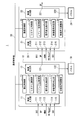
- FIG. 1 is a functional block diagram illustrating a configuration of a display system 1 exemplified as the first embodiment.
- the display system 1 includes a first display device 10 exemplified as a first display device, a second display device 20 exemplified as a second and subsequent display devices, and a communication control line 30. .
- a display system including two display devices, the first display device 10 and the second display device 20, is illustrated, but the third and subsequent display devices are daisy chained in the subsequent stage of the second display device 20. Connected to form a display system.
- the first display device 10 and the second display device 20 have the same device configuration. That is, in the first embodiment, the display system can be configured with the first display device to which a video input signal is input as the first display device and the same display device as the second and subsequent display devices. Illustrated. By configuring a display system with display devices having the same device configuration, the display devices can be arranged without worrying about the connection order of which display devices.
- the first display device 10 includes a video input unit 11, a video output unit 12, a communication control unit 13, a system control unit 14, a command transmission / reception unit 15, a signal change detection unit 16, a video signal determination unit 17, and a video signal adjustment unit 18. And a panel 19.
- the video input unit 11 includes a DVI (Digital Visual Interface) input unit 111, a DP input unit 112, an HDMI input unit 113, an HD-BaseT (registered trademark) input unit 114, and an SDI (Serial Digital Interface) input unit 115.
- FIG. 1 illustrates the case where the panel 19 is configured to be connected to the outside of the first display device 10, the panel 19 is included in the display device 10.
- the display device of the present embodiment may be a device that does not include a panel and controls display of the panel. The same applies to the panel 29 in the second display device 20 described below.
- the second display device 20 includes a video input unit 21, a video output unit 22, a communication control unit 23, a system control unit 24, a command transmission / reception unit 25, a signal change detection unit 26, a video signal determination unit 27, and a video signal adjustment unit 28. And a panel 29.
- the video input unit 21 includes a DVI input unit 211, a DP input unit 212, an HDMI input unit 213, an HD-BaseT input unit 214, and an SDI input unit 215.
- the communication control line 30 is a control line that connects the first display device 10 and the second display device 20 in a communicable manner.
- a priority LAN Local Area
- Ethernet registered trademark
- the communication control line 30 may be connected to a PC (not shown) or a third or subsequent display device.
- the video input unit 11 has interfaces for video input signals of the DVI input unit 111, the DP input unit 112, the HDMI input unit 113, the HD-BaseT input unit 114, and the SDI input unit 115.
- the input cable can be connected.
- the video input unit 11 can switch the plurality of types of video input signals that are input. Switching of the video input signal can be performed by an explicit selection operation such as a button operation by the user.
- the video input signal can be switched by the video input unit 11 detecting the physical connection of the input cable or detecting the input of the video input signal.
- the video output unit 12 includes a DP output unit 121 and a panel connection unit 122.
- the video signal output from the DP output unit 121 and the panel connection unit 122 is a DP signal.
- the DP signal output from the DP output unit 121 is input to the DP input unit 212 of the video input unit 21 of the second display device. That is, it is assumed that DP signals are input from the preceding display device to the second and subsequent display devices by daisy chain connection.
- the video signal output from the panel connection unit 122 is output to the panel 19.
- the 1st display system 1 has illustrated the case where the 2nd display apparatus 20 is connected as a display apparatus after the 2nd unit.
- the configuration of the device may be a configuration in which three or more display devices are connected.
- the video output unit and the video input unit are connected one-to-one, and a case where a video signal is transmitted by so-called daisy chain connection in which a plurality of display devices are connected in a row is illustrated.
- one video output unit may be connected to a plurality of video input units to transmit a video signal.
- the relationship between the video input signal input from the video input unit 11 and the video signal output from the video output unit 12 will be described.
- the video input signal input from the video input unit 11 is an HDMI signal
- a distributor is required in order to distribute the HDMI signal and output it to the subsequent display device.
- a display device capable of inputting a plurality of types of video input signals as the number of types of video input signals increases, it is necessary to provide a distributor according to the number of video input signals, resulting in an increase in cost.
- a large display system such as a public display
- a large number of display devices are used.
- the number of distributors can be reduced by inputting a single video signal such as a DP signal or a DVI signal through daisy chain connection.
- the video related information included in the video input signal input to the first unit may not be included in the output video signal.
- the output video signal lacks HDMI video related information.
- the communication control unit 13 communicates with the communication control unit 23 of the second display device 20 via the communication control line 30.
- the communication control unit 13 is a network controller, for example.
- the communication control unit 13 transmits communication data indicating a change in the video input signal input to the video input unit 11 to the communication control unit 23.
- Communication data transmitted by the communication control unit 13 can be transmitted in a communication procedure based on the communication protocol of the communication control line 30.
- the communication control unit 13 transmits communication data indicating the change in the video input signal to the third and subsequent display devices. Can do.
- the communication control unit 13 exemplifies a case where wired communication via the communication control line 30 is controlled.
- the communication control unit 13 may control wireless communication, for example.
- the system control unit 14 performs overall control of the first display device 10.
- the system control unit 14 includes a video input unit 11, a video output unit 12, a communication control unit 13, a command transmission / reception unit 15, a signal change detection unit 16, a video signal determination unit 17, and a video signal adjustment unit 18.
- the case of controlling is illustrated.
- the system control unit 14 includes, for example, a CPU (Central Processing Unit) and operates according to a program.
- CPU Central Processing Unit
- the command transmission / reception unit 15 generates a communication command indicating a change in the video input signal and transmits it to the communication control unit 13 when there is a change in the video input signal input to the video input unit 11.
- the communication control unit 13 transmits communication data including the transmitted communication command according to the communication protocol of the communication control line 30.
- the command reception function of the command transmission / reception unit 15 will be described in the command transmission / reception unit 25.
- the signal change detection unit 16 detects whether or not there is a change in the video input signal input from the video input unit 11.
- the signal change detection unit 16 detects a change in the video input signal when the video signal needs to be readjusted due to a change in the video input signal input from the video input unit 11. For example, this is a case where the gradation range or scaling of the video input signal changes.
- the change in the video input signal can be detected, for example, by determining the change in the video related information described with reference to FIG. Further, it can be detected by detecting the explicit switching of the video input signal input to the video input unit 11 by the user.
- the video signal determination unit 17 is not used in the first display device 10. That is, the video signal determination unit 17 is used when the first display device 10 is arranged as a second or subsequent display device. Details of the operation of the video signal determination unit 27 in the second display device 20 will be described later.
- the video signal adjustment unit 18 adjusts the video input signal input to the video input unit 11 according to the display specifications of the panel 19, and outputs the adjusted video signal to the video output unit 12. For example, the video signal adjustment unit 18 adjusts the video signal to be output based on the video related information included in the video input signal input from the video input unit 11.
- the video related information will be described with reference to FIG.
- FIG. 2 is a table showing details of the AVI Information included in the Infoframe information, which is exemplified as the video related information when the video input signal is an HDMI signal.
- the video input signal described with reference to FIG. 1 includes an HDMI signal including video related information.
- video-related information when the video input signal is an HDMI signal will be described as an example.
- AVI Information includes the illustrated video related information.
- a case where a video signal is adjusted using “Scan Information” and “RGB Quantization Range” in the video related information is exemplified. Therefore, in FIG. 2, “Scan Information” and “RGB Quantization Range” among the video related information will be described, and description of other video related information will be omitted.
- “Scan Information” is scaling information for adjusting the display range of the video. For example, overscan is when scaling is greater than 0%. For example, when video is output to a television receiver, overscan is set to 15%. On the other hand, underscan indicates a case where scaling is less than 0%.
- Devices that output HDMI signals include devices that can change the scaling according to the connection destination of the HDMI signals.
- the output HDMI signals include “Scan Information” indicating the scaling information of the output HDMI signals as video-related information. Can be included. Therefore, in the display devices connected to the second and subsequent units that cannot obtain the information of “Scan Information”, a black belt portion may be generated in the peripheral portion of the panel because correct scaling is not performed.
- RGB Quantization Range indicates the gradation range of the RGB signal of the video signal. For example, when “RGB Quantization Range” is “Limited”, it indicates that the gradation range of the RGB signal is 16 to 235. Further, when “RGB Quantization Range” is “Full” (full range), it indicates that the gradation range of the RGB signal is 0 to 255. If the gradation range of the video signal and the gradation range of the video displayed on the display device are different, the color of the displayed video is not displayed correctly.
- the gradation range of the video signal is a limited range of 16 to 235 and the gradation range of the display device is set to a full range of 0 to 255
- the gradation value 16 indicating black of the video signal is Since the display device has 16 gradations higher than the gradation value 0 indicating black, the black color of the video signal is displayed whitish on the display device.
- the gradation range of the video signal is a full range of 0 to 255 and the gradation range of the display device is set to a limited range of 16 to 235
- the entire displayed image is originally displayed. It becomes darker and darker than that. Therefore, in the display devices connected to the second and subsequent devices that cannot obtain the information of “RGB Quantization Range”, the color of the image may not be displayed correctly.
- the signal change detection unit 16 described with reference to FIG. 1 can detect whether or not there is a change in the dominant video signal based on the above-described “Scan Information” or “RGB Quantization Range” value included in the video input signal. .
- Scan Information or “RGB Quantization Range” value included in the video input signal.
- RGB Quantization Range value included in the video input signal.
- the video signal adjustment unit 18 adjusts the gradation range and scaling of the video input signal input from the video input unit 11 based on the video related information described above,
- the video signal whose gradation range and scaling are adjusted is output to the panel 19 via the video output unit 12.
- the panel 19 and the panel 29 have a full-range gradation range. That is, the video signal adjustment unit 18 always adjusts the gradation range of the video input signal input from the video input unit 11 to the full range according to the gradation range of the panel 19.
- the panel 19 displays a video based on a video signal (DP signal) output from the panel connection unit 122 of the video output unit 12.
- DP signal video signal
- the panel 19 is arranged adjacent to the panel 29 connected to the second display device. Therefore, if the image displayed on the panel 19 and the image displayed on the panel 29 are different in color and screen size, there is a problem that the image mismatch is noticeable.
- the configuration of the second display device 20 is basically the same as that of the first display device 10. Therefore, the description of the same operation as that of the first display device 10 is omitted.
- the video input unit 21 receives a video signal based on the video input signal received by the first display device 10 exemplified as another display device.
- the video input unit 21 has interfaces for video input signals of the DVI input unit 211, the DP input unit 212, the HDMI input unit 213, the HD-BaseT input unit 214, and the SDI input unit 215, respectively.
- the DP signal is input to the DP input unit 112 in the video input unit 21, and other signal input units are not used.
- the second display device 20 can also be used as a first display device to which a video input signal is input. Note that the DP signal input to the DP input unit 212 does not include the video-related information described in FIG.
- the communication control unit 23 communicates with the communication control unit 23 of the first display device 10 via the communication control line 30.
- the communication control unit 23 receives communication data indicating a change in the video input signal input to the video input unit 11 of the first display device 10 from the communication control unit 13. Note that the same operation as that of the communication control unit 23 is performed even when the third and subsequent display devices are connected.
- the command transmission / reception unit 25 sends a video input signal to the video signal determination unit 27. Notify that has changed.
- the command transmission / reception unit 25 also has the command transmission function described in the command transmission / reception unit 15.
- the signal change detection unit 26 detects whether or not the video input signal has changed in the first display device 10 input from the video input unit 21. However, in this embodiment, since the DP signal is always input to the video input unit 21 via the DP signal input unit 212, it does not function in the second display device 20.
- the video signal determination unit 27 determines the video signal input from the video input unit 21 based on the communication data received by the communication control unit 23.
- the video signal determination unit 27 determines the gradation range of the RGB signal of the DP signal input from the video input unit 21 when the signal change detection unit 26 detects a change in the video input signal in the first display device. Execute. Details of the video signal determination unit 27 will be described with reference to FIG.
- FIG. 3 is a block diagram showing a first configuration of the video signal determination unit 27.
- the video signal determination unit 271 exemplified as the first configuration of the video signal determination unit 27 includes a minimum luminance measurement unit 2711 and a maximum luminance measurement unit 2712.
- the video signal determination unit 2727 measures the minimum luminance of the video signal by the minimum luminance measurement unit 2711, measures the maximum luminance by the maximum luminance measurement unit 2712, and the luminance range obtained from the measured minimum luminance and maximum luminance is predetermined. It is determined whether it is within the range.
- the minimum luminance measuring unit 2711 measures the minimum luminance of the RGB signal of the DP signal input from the video input unit 21.
- the maximum luminance measuring unit 2712 measures the maximum luminance of the RGB signal of the DP signal input from the video input unit 21.
- the luminance of the RGB signal can be detected based on the signal level of the RGB signal, for example.
- the video signal determination unit 271 The DP signal input from the input unit 21 is determined to be a limited range gradation range exemplified as the first gradation range.
- the minimum luminance measured by the minimum luminance measurement unit 2711 is less than or equal to a preset minimum luminance, or the maximum luminance measured by the maximum luminance measurement unit 2712 is greater than or equal to a preset maximum luminance.
- the DP signal input from the video input unit 21 is determined to be a full-range gradation range exemplified as a second gradation range having a gradation range wider than the first gradation range.
- the determination of gradation can be performed, for example, by measuring the luminance of the RGB signal within a predetermined time. Further, it can be performed by measuring the luminance in the RGB signal of the video displayed at a predetermined position on the panel 29. Further, gradation determination may be performed based on the distribution of gradations included in the video signal.
- the video signal determination unit 271 outputs the determination result of the limited range or full range gradation range to the video signal adjustment unit 28. Above, description of the video signal determination part 271 illustrated as a 1st structure of the video signal determination part 27 using FIG. 3 is complete
- the video signal adjustment unit 28 adjusts the video signal (DP signal) input from the video input unit 21 based on the determination result of the gradation range input from the video signal determination unit 27.
- the adjusted video signal (DP signal) is output to the video output unit 22.
- the video signal adjustment unit 28 has two gradation processing modes.
- the first processing mode is a mode in which the input DP signal is expanded from the limited range to the full range.
- the second processing mode is a processing mode in which the input DP signal is not expanded.
- the two processing modes are set, for example, depending on the presence or absence of a flag in the internal memory of the video signal adjustment unit 28.
- the video signal adjustment unit 28 sets a flag for setting the gradation processing mode to the enlargement processing mode. That is, the video signal adjustment unit 28 set to the processing mode of the expansion process extends the gradation range from 16 to 235 to 16 to 235 for the video signal input from the video input unit 21.
- the video signal adjustment unit 28 sets a flag for canceling the processing mode of the enlargement process described above. In other words, the video signal adjustment unit 28 whose processing mode of enlargement processing has been canceled does not adjust the gradation range for the full-range video signal input from the video input unit 21.
- the video signal adjustment unit 28 also has a function of adjusting the video signal based on the video related information of the video input signal input from the video input unit 21 in the same manner as the video signal adjustment unit 18. That is, even when the second display device 20 is the first display device to which a video input signal is input, the video signal adjustment unit 28 can adjust the video signal based on the video related information.
- the panel 29 displays a video based on a video signal (DP signal) output from the panel connection unit 222 of the video output unit 22. Due to the setting of the gradation range described above, the gradation range of the video signal becomes the same full range as the gradation range of the panel 29, the image displayed on the panel 29 has the same color as the image displayed on the panel 19, and the images do not match. Can be prevented.
- DP signal video signal
- the timing at which the video signal determination unit 271 described with reference to FIG. 3 determines the gradation range is when communication data indicating a change in the video input signal of the first display device 10 is received as described above.
- the gradation range may not be correctly determined depending on the video signal input from the video input unit 21.
- the first display device 10 notifies the second and subsequent display devices of the timing for determining the gradation range via the communication control line, whereby the optimal timing in the second and subsequent display devices.
- the second and subsequent display devices can automatically determine the gradation range based on the communication data indicating the change in the video input signal transmitted from the first display device 10. Accordingly, communication data indicating a change in the video input signal functions as a request command for automatic determination.
- description of the functional block diagram which shows the structure of the display system 1 illustrated in 1st Embodiment using FIG. 1 is complete
- FIG. 4 is a flowchart showing the operation of the first display device 10 exemplified as the first display device.
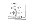
- FIG. 5 is a flowchart showing the operation of the second display device 20 exemplified as the second and subsequent display devices.
- the signal change detection unit 16 determines whether or not there is a change in the video input signal input from the video input unit 11 (step S11). If it is determined that there is no change in the video input signal (step S11; NO), the process returns to step S11, and the process in step S11 is repeated until there is a change in the video input signal.
- step S11 when it is determined that there is a change in the video input signal (step S11; YES), the signal change detection unit 16 determines whether there is a change in the AVI Information described in FIG. 2 (step S12). If it is determined that there is no change in AVI Information (step S12; NO), the process returns to step S11. On the other hand, when it is determined that there is a change in AVI Information (step S12; YES), the signal change detection unit 16 generates a communication command indicating a change in the video input signal to the command transmission / reception unit 15. . The generated communication command is transmitted as a request command for automatic determination from the communication control unit 13 to the second and subsequent display devices (step S13).
- the command transmission / reception unit 25 of the second display device 20 determines whether or not an automatic determination request command has been received (step S21). If it is determined that an automatic determination request command has not been received (step S11; NO), the process returns to step S21, and the process of step S21 is repeated until an automatic determination request command is received. On the other hand, if it is determined that a request command for automatic determination has been received (step S11; NO), the command transmission / reception unit 25 notifies the video signal determination unit 27 of the reception of the command and is input from the video input unit 21. Automatic determination is performed on the gradation range of the video level of the DP signal (step S22).
- the video signal determination unit 27 determines whether or not the gradation range is within the limited range (step S23). When the gradation range is within the limited range (step S23; YES), the video signal adjustment unit 28 is set to enlargement processing setting (step S24). On the other hand, when the gradation range is not within the limited range (step S23; NO), the video signal adjustment unit 28 cancels the enlargement processing setting (step S25). After executing the process of step S24 or the process of step S25, the process returns to the process of step S21. Above, description of operation
- FIG. 6 is a block diagram illustrating a configuration of a video signal determination unit 272 exemplified as a second configuration of the video signal determination unit 27.
- the video signal video signal determination unit 272 includes a minimum luminance measurement unit 2721, a maximum luminance measurement unit 2722, and a peripheral luminance measurement unit 2723.
- the minimum luminance measuring unit 2721 measures the minimum luminance of the RGB signal of the DP signal input from the video input unit 21 in the same manner as the minimum luminance measuring unit 2711 described in FIG.
- the maximum luminance measuring unit 2722 measures the maximum luminance of the RGB signal of the DP signal input from the video input unit 21, similarly to the maximum luminance measuring unit 2712. Based on the determination of the minimum luminance measuring unit 2721 and the maximum luminance measuring unit 2722, the DP signal input from the video input unit 21 is within the gradation range of the limited range or the full range of the levels as in the video signal determination unit 271. It is determined whether it is in the adjustment range.
- the peripheral luminance measuring unit 2723 confirms the scaling of the video signal (DP signal) input from the video input unit 21 by measuring the luminance of the panel peripheral portion of the video displayed on the panel 29 based on the video signal.
- the DP signal input from the video input unit 21 does not include the scaling information included in the HDMI signal described with reference to FIG. Therefore, if the DP signal scaling setting and the scaling setting on the panel 29 do not coincide with each other, a black band portion may occur in the peripheral portion of the image displayed on the panel 29.
- the peripheral luminance measurement unit 2723 determines whether or not a black belt portion has occurred in the peripheral portion of the video by measuring the luminance of the peripheral portion of the video, and detects a mismatch in scaling. Above, description of the block diagram which shows the structure of the video signal determination part 272 using FIG. 6 is complete
- FIG. 7 is a diagram showing measurement points provided in the peripheral part of the panel 29.
- an output video 191 from a PC (not shown) is displayed on the display screen of the panel 29.
- a black belt portion may occur in the peripheral portion 192 of the display screen.
- eight measurement points P1 to P8, which are indicated by circles clockwise from the upper left, are set.
- the number and shape of the measurement points are arbitrary.
- the four points illustrated as P1, P3, P5, and P7 may be used as the measurement points. Further, eight or more measurement points may be set.
- the luminance measurement range is also arbitrary.
- the measurement points are illustrated by circles having a predetermined range.
- the luminance in the predetermined range can be an average value of the luminance in the measured range.
- the luminance of one point for example, one pixel for each of RGB
- the scaling mismatch is measured by the occurrence of a black belt portion in the peripheral portion of the video. Therefore, it is desirable to set the number and shape of measurement points according to the shape of the black belt portion to be detected.
- the black belt portion can be measured by a portion in which the luminance is equal to or less than a predetermined value being continuous in a belt shape.
- FIG. 8 is a functional block diagram showing a configuration of the display system 2 exemplified as the second embodiment.
- the display system 2 includes a first display device 40 exemplified as the first display device, a second display device 50 exemplified as the second and subsequent display devices, and a communication control line 60. .
- the third and subsequent display devices are provided in the subsequent stage of the second display device 50.
- a display system can be configured by daisy chain connection.
- the first display device 40 and the second display device 50 each have a dedicated device configuration. That is, in the second embodiment, the first display device 40 is always used for the display device to which the video input signal is first input, and the second display device 50 is used for the second and subsequent display devices.
- a display system is comprised is illustrated.
- the configuration of the display device can be simplified and the cost can be reduced.
- the cost of the second and subsequent display devices can be reduced.
- the first display device 40 includes a video input unit 41, a video output unit 42, a communication control unit 33, a system control unit 44, a command transmission / reception unit 45, a signal change detection unit 46, a video signal adjustment unit 48, and a panel 49. Prepare.
- the first display device 40 does not include the video signal determination unit 17 included in the first display device 10.
- the video signal determination unit 17 is a function used in display devices connected to the second and subsequent units, and can be omitted in the first display device.
- the video input unit 41, video output unit 42, communication control unit 33, system control unit 44, command transmission / reception unit 45, signal change detection unit 46, video signal adjustment unit 48, and panel 49 In the first display device 10, the video input unit 11, the video output unit 12, the communication control unit 13, the system control unit 14, the command transmission / reception unit 15, the signal change detection unit 16, the video signal adjustment unit 18, and the panel 19 are displayed.
- the configuration is the same as in FIG.
- the second display device 50 includes a video input unit 51, a video output unit 52, a communication control unit 53, a system control unit 54, a command transmission / reception unit 55, a video signal determination unit 57, a video signal adjustment unit 58, and a panel 59.
- the second display device 50 does not include the signal change detection unit 26 included in the second display device 20.
- the signal change detection unit 26 has a function of detecting a change in the input video input signal, and can be omitted in the second and subsequent display devices to which the video input signal is not directly input.
- the video input unit 51 has a DP input unit 511.
- the video input unit 51 does not include the DVI input unit 411, the HDMI input unit 413, the HD-BaseT input unit 414, and the SDI input unit 415 that the video input unit 41 has. That is, in the second embodiment, the case where the DP signal is always input in a daisy chain is illustrated for the second and subsequent display devices. By simplifying the input port of the video input unit 51, the cost of the second and subsequent display devices can be reduced. In the second embodiment, the case where the DP signals are connected in a daisy chain is illustrated, but the connection may be made using, for example, a DVI signal other than the DP signal.
- the configuration is the same as in FIG. Above, description of the display system 2 in 2nd Embodiment using FIG. 8 is complete
- FIG. 9 is a functional block diagram illustrating the configuration of the display device.
- a display device 70 receives a video input unit 71 to which a video signal based on a video input signal received by another display device is input, and communication data indicating a change in the video input signal from another display device.
- the video signal determination unit 77 that determines the video signal input from the video input unit 71 based on the communication data received by the communication control unit 73, and the determination result of the video signal determination unit 77.
- a video signal adjustment unit 78 for adjusting the video signal.
- description of the structure of the display apparatus 70 using FIG. 9 is complete
- the first display device 10, the second display device 20, the first display device 40, and the second display device 50 described above may be realized by a computer to which a panel can be connected.
- the program for realizing the function of each functional block may be recorded on a computer-readable recording medium, and the program recorded on the recording medium may be read into the computer system and executed.
- the “computer system” here includes an OS and hardware such as peripheral devices.
- the “computer-readable recording medium” refers to a storage device such as a flexible medium, a magneto-optical disk, a portable medium such as a ROM or a CD-ROM, and a hard disk incorporated in a computer system.
- the “computer-readable recording medium” dynamically holds a program for a short time like a communication line when transmitting a program via a network such as the Internet or a communication line such as a telephone line.
- a volatile memory inside a computer system serving as a server or a client in that case may be included and a program held for a certain period of time.
- the program may be a program for realizing a part of the above-described functions, and may be a program capable of realizing the functions described above in combination with a program already recorded in a computer system. It may be realized using a programmable logic device such as an FPGA (Field Programmable Gate Array).
- FPGA Field Programmable Gate Array
- first display device 10 The functions of the first display device 10, the second display device 20, the first display device 40, and the second display device 50 will be described with reference to FIGS. 1, 3, 6, 8, and the like. As long as it has the functions described above, a plurality of illustrated functional blocks may be mounted together in one functional block, or the illustrated one functional block may be divided and mounted as a plurality of functional blocks.
- the embodiments exemplified above can be applied to a display device, a display system, a display method, and a display program.
- the video signal determination unit measures a minimum luminance and a maximum luminance of the video signal, and determines whether or not a luminance range obtained from the measured minimum luminance and the maximum luminance is within a predetermined range.
- the display device according to appendix 1. (Appendix 3)
- the video signal determination unit determines that the gradation range of the video signal is the first gradation range when the luminance range is within a predetermined range, and the luminance range is within the predetermined range. If not, it is determined that the gradation range of the video signal is a second gradation range having a gradation range wider than the first gradation range, The display device according to appendix 2, wherein the video signal adjustment unit adjusts the gradation range of the video signal based on the gradation range determined by the video signal determination unit.
- Appendix 4 Any one of appendices 1 to 3, wherein the video signal determination unit measures a luminance of a peripheral portion of a video displayed based on the video signal, and determines scaling of the video signal based on the measured luminance of the peripheral portion. Or the display device according to claim 1.
- Appendix 5 A video output unit that outputs a video signal based on the received video input signal;
- a signal change detector for detecting a change in the video input signal;
- a display device comprising: a communication control unit configured to transmit communication data indicating a change in the video input signal to another display device when the signal change detection unit detects a change in the video input signal.
- the first display device includes: A video output unit for outputting a video signal to the second display device based on the received video input signal; A signal change detector for detecting a change in the video input signal; A communication control unit that transmits communication data indicating a change in the video input signal to the second display device when the signal change detection unit detects a change in the video input signal;
- the second display device includes: A video input unit to which a video input signal output from the first display device is input; A communication control unit that receives communication data indicating a change in the video input signal from the first display device; A video signal determination unit for determining a video signal input from the video input unit based on the communication data received by the communication control unit; A display system comprising: a video signal adjustment unit that adjusts the video signal based on a determination result of the video signal determination unit.
- the video signal determination step when the luminance range is within a predetermined range, it is determined that the gradation range of the video signal is the first gradation range, and the luminance range is within the predetermined range. If not, it is determined that the gradation range of the video signal is a second gradation range having a gradation range wider than the first gradation range, The display method according to claim 8, wherein, in the video signal adjustment step, the gradation range of the video signal is adjusted based on the gradation range determined in the video signal determination step.
- Appendix 10 Any one of appendixes 7 to 9, wherein, in the video signal determination step, the luminance of the peripheral portion of the video displayed based on the video signal is measured, and the scaling of the video signal is determined based on the measured peripheral luminance.
- the display method according to 1. (Appendix 11) A video output process for outputting a video signal based on the received video input signal; A signal change detection step of detecting a change in the video input signal; A communication control step of transmitting communication data indicating the change of the video input signal to another display device when the change of the video input signal is detected in the signal change detection step.
- (Appendix 13) Video input processing in which a video signal based on a video input signal received by another display device is input; A reception process for receiving communication data indicating a change in the video input signal from the other display device; A video signal determination process for determining the video signal based on the communication data received in the reception process; A display program for causing a computer to execute a video signal adjustment process for adjusting the video signal based on a determination result in the video signal determination process.
- the minimum luminance and the maximum luminance of the video signal are measured, and it is determined whether the luminance range obtained from the measured minimum luminance and the maximum luminance is within a predetermined range.
- Appendix 16 Any one of appendices 13 to 15, wherein in the video signal determination process, luminance of a peripheral portion of a video displayed based on the video signal is measured, and scaling of the video signal is determined based on the measured luminance of the peripheral portion.
- the display program according to 1. (Appendix 17) Video output processing for outputting a video signal based on the received video input signal; A signal change detection process for detecting a change in the video input signal; A display program for causing a computer to execute a communication control process for transmitting communication data indicating a change in the video input signal to another display device when a change in the video input signal is detected in the signal change detection process.
- a video output process for outputting the video signal to the second display device based on the received video input signal;
- a signal change detection process for detecting a change in the video input signal;
- a communication control process for transmitting communication data indicating a change in the video input signal to the second display device when a change in the video input signal is detected in the signal change detection process;
- Including In the second display device Video input processing in which the video signal output from the first display device is input;
- a communication control process for receiving communication data indicating a change in the video input signal from the first display device;
- a video signal determination process for determining the video signal based on the communication data received in the communication control process;
- a display program for causing a computer to execute video signal adjustment processing for adjusting the video signal based on a determination result in the video signal determination step.
Abstract
Description
また、複数のディスプレイをデイジーチェーン接続し、信号源から供給される映像信号が前段のディスプレイから後段のディスプレイに順次送られるディスプレイがある。
また、入力信号の信号規格がフルレンジかリミットレンジかを自動的に判定する液晶テレビ装置がある。
また、映像信号の画面の一番上から1水平ラインずつ順次輝度レベルを計測する映像表示装置がある。
上記の技術は、例えば、特許文献1~4に記載されている。 There is a multi-screen display device that includes a plurality of video display units and transmits a command to start brightness correction processing to a slave device when the power is turned on.
There is also a display in which a plurality of displays are connected in a daisy chain, and a video signal supplied from a signal source is sequentially sent from a front display to a rear display.
There is also a liquid crystal television apparatus that automatically determines whether the signal standard of an input signal is a full range or a limit range.
There is also a video display device that sequentially measures the luminance level one horizontal line at a time from the top of the video signal screen.
The above techniques are described in, for example,
HDMI信号が入力された表示装置は、映像入力信号に含まれるInfoframe情報を確認して、表示する映像の階調やスケーリング等の調整を行うことができる。 Some video input signals input to the display device include video-related information such as scaling, which is information indicating the video gradation information and the video display range. For example, a High-Definition Multimedia Interface (HDMI) (registered trademark) signal, which is one of video input signals, includes Infoframe information including AVI (Auxiliary Video Information) as video related information. The AVI includes, for example, a parameter of “RGB Quantization Range” indicating whether the gradation range of the RGB signal is a limited range of 16 to 235 or a full range of 0 to 256. Further, the AVI includes a “Scan Information” parameter indicating video scaling.
The display device to which the HDMI signal is input can check the Infoframe information included in the video input signal and adjust the gradation and scaling of the video to be displayed.
そこで、本発明は、映像入力信号が直接入力されない表示装置において表示映像の調整を可能とする、表示装置、表示システム、表示方法、及び表示プログラムを提供することを目的とする。 However, in the conventional multi-system display device in which a plurality of display devices (monitors) are connected by daisy chain connection or the like, the video input of the preceding display device is aimed at reducing the number of video distributors that distribute the video input signal. There is a type that converts a video input signal input to the unit into a video signal, and outputs the converted video signal to a panel of the device itself and to a display device at a subsequent stage. For example, when a video signal is output from a DP (Display Port), video related information cannot be included in the video signal output from the DP. Therefore, even when the video input signal includes video related information like the HDMI signal, the video related information of the HDMI signal is not input to the subsequent monitor. That is, the display device in the previous stage can adjust the display video based on the video related information included in the input video input signal, whereas the display device in the subsequent stage in which the video signal lacking the video related information is input. The display image cannot be adjusted based on the image related information. Therefore, the video displayed on the front display device may be different from the video displayed on the rear display device. For example, when the video-related information includes information on the gradation range of the RGB signal, since the display device in the subsequent stage cannot adjust the gradation range, the color of the video displayed on the display device in the subsequent stage is displayed on the monitor in the previous stage. In some cases, it may differ from the image color. In addition, when the video related information includes scaling information, the display device in the subsequent stage cannot adjust the scaling, so a black belt part (including a black frame shape) may be displayed around the monitor in the subsequent stage. there were.
SUMMARY An advantage of some aspects of the invention is that it provides a display device, a display system, a display method, and a display program that enable adjustment of a display image in a display device to which a video input signal is not directly input.
先ず、図1を用いて、第1の実施形態における表示システムを説明する。図1は、第1の実施形態として例示する表示システム1の構成を示す機能ブロック図である。 [First Embodiment]
First, the display system according to the first embodiment will be described with reference to FIG. FIG. 1 is a functional block diagram illustrating a configuration of a
映像入力部11は、DVI入力部111、DP入力部112、HDMI入力部113、HD-BaseT入力部114、及び、SDI入力部115それぞれの映像入力信号のインターフェイスを有して、それぞれのインターフェイスの入力ケーブルを接続可能にしている。映像入力部11は、入力される上記複数種類の映像入力信号を切り替えることができる。映像入力信号の切り換えは、例えばユーザによるボタン操作等、明示的な選択操作により行うことができる。また、映像入力信号の切り換えは、映像入力部11が、入力ケーブルの物理的な接続を検出することにより、又は映像入力信号の入力を検出することにより行うことができる。 First, the device configuration of the
The
本実施形態では、第1の表示システム1は、2台目以降の表示装置として第2の表示装置20が接続される場合を例示している。しかし、装置の構成は3台以上の表示装置を接続する構成であってもよい。
また、本実施形態では、映像出力部と映像入力部が1対1で接続されて複数の表示装置が1列状に接続される所謂デイジーチェーン接続によって映像信号が送信される場合を例示するが、例えば、1の映像出力部が複数の映像入力部に接続されて映像信号を送信するようにしてもよい。 The
In this embodiment, the
In this embodiment, the video output unit and the video input unit are connected one-to-one, and a case where a video signal is transmitted by so-called daisy chain connection in which a plurality of display devices are connected in a row is illustrated. For example, one video output unit may be connected to a plurality of video input units to transmit a video signal.
例えば、映像入力部11から入力される映像入力信号がHDMI信号である場合、映像出力部12からHDMI信号を分配して出力するためには、HDMI信号の分配器を設けて出力する必要がある。また、2台目以降の表示装置においても、HDMI信号を分配して後段の表示装置に出力するためには同様に分配器が必要になる。複数種類の映像入力信号が入力可能な表示装置においては、映像入力信号の種類が増えると、分配器も映像入力信号の数に合わせて備える必要があり、コストが上昇する。例えばパブリックディスプレイ等の大型表示システムにおいては、使用する表示装置の数が多い。従って、2第目以降の表示装置において、DP信号やDVI信号等の単一の映像信号をデイジーチェーン接続で入力することにより、分配器を削減することができる。しかし、映像入力信号と映像信号とが異なる場合、1台目に入力される映像入力信号に含まれている映像関連情報が、出力する映像信号には含まれない場合がある。例えば、映像入力信号がHDMIのときに、2台目以降の表示装置に出力される映像信号がDP信号であった場合、出力される映像信号には、HDMIの映像関連情報が欠落することとなる。 Here, the relationship between the video input signal input from the
For example, when the video input signal input from the
図1で説明した映像入力信号には、映像関連情報を含むHDMI信号がある。本実施形態では、映像入力信号がHDMI信号の場合における映像関連情報を例示して説明する。
図2において、AVI Informationには、図示する映像関連情報が含まれる。本実施形態では、映像関連情報の中で、「Scan Information」及び「RGB Quantization Range」を用いて映像信号を調整する場合を例示する。したがって、図2においては、映像関連情報のうち、「Scan Information」及び「RGB Quantization Range」について説明し、他の映像関連情報の説明は省略する。 FIG. 2 is a table showing details of the AVI Information included in the Infoframe information, which is exemplified as the video related information when the video input signal is an HDMI signal.
The video input signal described with reference to FIG. 1 includes an HDMI signal including video related information. In the present embodiment, video-related information when the video input signal is an HDMI signal will be described as an example.
In FIG. 2, AVI Information includes the illustrated video related information. In the present embodiment, a case where a video signal is adjusted using “Scan Information” and “RGB Quantization Range” in the video related information is exemplified. Therefore, in FIG. 2, “Scan Information” and “RGB Quantization Range” among the video related information will be described, and description of other video related information will be omitted.
以上で、図2を用いた、映像関連情報として例示するAVI Informationの説明を終了する。 The signal
Above, description of AVI Information illustrated as video relevant information using FIG. 2 is complete | finished.
最小輝度測定部2711は、映像入力部21から入力されるDP信号のRGB信号の最小輝度を測定する。最大輝度測定部2712は、映像入力部21から入力されるDP信号のRGB信号の最大輝度を測定する。RGB信号の輝度は、例えばRGB信号の信号レベルを基に検出することができる。映像信号判定部271は、最小輝度測定部2711が測定した最小輝度が予め設定された最小輝度より大きく、かつ最大輝度測定部2712が測定した最大輝度が予め設定された最大輝度より小さい場合、映像入力部21から入力されるDP信号は、第1の階調範囲とて例示するリミテッドレンジの階調範囲であると判定する。
一方、映像信号判定部271は、最小輝度測定部2711が測定した最小輝度が予め設定された最小輝度以下であり、または最大輝度測定部2712が測定した最大輝度が予め設定された最大輝度以上である場合、映像入力部21から入力されるDP信号は、第1の階調範囲より広い階調範囲を有する第2の階調範囲として例示するフルレンジの階調範囲であると判定する。
階調の判定は、例えば、所定の時間内におけるRGB信号における輝度を測定することにより行うことができる。また、パネル29の所定の位置に表示される映像のRGB信号における輝度を測定することにより行うことができる。また、映像信号に含まれる階調の分布に基づき階調の判定を行ってもよい。
映像信号判定部271は、リミテッドレンジ又はフルレンジの階調範囲の判定結果を映像信号調整部28に出力する。
以上で、図3を用いた、映像信号判定部27の第1の構成として例示した映像信号判定部271の説明を終了する。 The video signal determination unit 2727 measures the minimum luminance of the video signal by the minimum luminance measurement unit 2711, measures the maximum luminance by the maximum luminance measurement unit 2712, and the luminance range obtained from the measured minimum luminance and maximum luminance is predetermined. It is determined whether it is within the range.
The minimum luminance measuring unit 2711 measures the minimum luminance of the RGB signal of the DP signal input from the
On the other hand, in the video
The determination of gradation can be performed, for example, by measuring the luminance of the RGB signal within a predetermined time. Further, it can be performed by measuring the luminance in the RGB signal of the video displayed at a predetermined position on the
The video
Above, description of the video
映像信号調整部28は、2つの階調処理の処理モードを有している。1つ目の処理モードは、入力されたDP信号をリミテッドレンジからフルレンジへの拡張処理を行うモードである。2つ目の処理モードは、入力されたDP信号の拡張処理を行わない処理モードである。2つの処理モードは、例えば、映像信号調整部28の内部メモリにフラグの有無によって設定される。
映像信号調整部28は、映像信号判定部27から入力された階調範囲がリミテッドレンジである場合、上記階調処理の処理モードを拡大処理の処理モードにするフラグ設定を行う。すなわち 、拡大処理の処理モードに設定された映像信号調整部28は、映像入力部21から入力される映像信号に対して階調範囲を16~235から16~235に拡張する。
一方、映像信号調整部28は、映像信号判定部27から入力された階調範囲がフルレンジである場合、上述した拡大処理の処理モードを解除するフラグ設定を行う。すなわち、拡大処理の処理モードが解除された映像信号調整部28は、映像入力部21から入力されるフルレンジの映像信号に対する階調範囲の調整をしない。
なお、映像信号調整部28は、映像信号調整部18と同様に映像入力部21から入力される映像入力信号の映像関連情報に基づく映像信号の調整を行う機能も有するものとする。すなわち、第2の表示装置20を映像入力信号が入力される1台目の表示装置とした場合においても、映像信号調整部28は映像関連情報に基づく映像信号の調整を行うことができる。 Returning to FIG. 1 again, the video
The video
When the gradation range input from the video
On the other hand, when the gradation range input from the video
Note that the video
以上で、図1を用いた、第1の実施形態で例示する表示システム1の構成を示す機能ブロック図の説明を終了する。 Note that the timing at which the video
Above, description of the functional block diagram which shows the structure of the
図4は、1台目の表示装置として例示する第1の表示装置10の動作を示すフローチャートである。図5は、2台目以降の表示装置として例示する第2の表示装置20の動作を示すフローチャートである。
図4において、信号変化検出部16は、映像入力部11から入力される映像入力信号の変化があったか否かを判断する(ステップS11)。
映像入力信号の変化がないと判断された場合(ステップS11;NO)、ステップS11の処理に戻り、映像入力信号の変化があるまでステップS11の処理を繰り返す。
一方、映像入力信号の変化があると判断された場合(ステップS11;YES)、信号変化検出部16は、図2で説明したAVI Informationに変化があったか否かを判断する(ステップS12)。
AVI Informationに変化がないと判断された場合(ステップS12;NO)、ステップS11の処理に戻る。
一方、AVI Informationに変化があると判断された場合(ステップS12;YES)、信号変化検出部16は、コマンド送受信部15に対して、映像入力信号の変化を示す通信コマンドを生成するようにする。生成された通信コマンドは自動判定のリクエストコマンドとして通信制御部13から2台目以降の表示装置へ送信される(ステップS13)。 Next, the operation of the
FIG. 4 is a flowchart showing the operation of the
In FIG. 4, the signal
If it is determined that there is no change in the video input signal (step S11; NO), the process returns to step S11, and the process in step S11 is repeated until there is a change in the video input signal.
On the other hand, when it is determined that there is a change in the video input signal (step S11; YES), the signal
If it is determined that there is no change in AVI Information (step S12; NO), the process returns to step S11.
On the other hand, when it is determined that there is a change in AVI Information (step S12; YES), the signal
自動判定のリクエストコマンドを受信していないと判断した場合(ステップS11;NO)、ステップS21の処理に戻り、自動判定のリクエストコマンドを受信するまでステップS21の処理を繰り返す。
一方、自動判定のリクエストコマンドを受信したと判断した場合(ステップS11;NO)、コマンド送受信部25は、映像信号判定部27に対してコマンドの受信を通知し、映像入力部21から入力されたDP信号のビデオレベルの階調範囲を自動判定を実行させる(ステップS22)。
ステップS22の処理を実行後、映像信号判定部27は、階調範囲がリミテッドレンジの範囲内であるか否かを判断する(ステップS23)。
階調範囲がリミテッドレンジの範囲内である場合(ステップS23;YES)、映像信号調整部28は、拡大処理設定に設定される(ステップS24)。
一方、階調範囲がリミテッドレンジの範囲内でない場合(ステップS23;NO)、映像信号調整部28は、拡大処理設定が解除される(ステップS25)。
ステップS24の処理又はステップS25の処理の実行後、ステップS21の処理に戻る。
以上で、図4及び図5を用いた、第1の表示システム1の動作の説明を終了する。 In FIG. 5, the command transmission /
If it is determined that an automatic determination request command has not been received (step S11; NO), the process returns to step S21, and the process of step S21 is repeated until an automatic determination request command is received.
On the other hand, if it is determined that a request command for automatic determination has been received (step S11; NO), the command transmission /
After executing the processing in step S22, the video
When the gradation range is within the limited range (step S23; YES), the video
On the other hand, when the gradation range is not within the limited range (step S23; NO), the video
After executing the process of step S24 or the process of step S25, the process returns to the process of step S21.
Above, description of operation | movement of the
以上で、図6を用いた、映像信号判定部272の構成を示すブロック図の説明を終了する。 The peripheral luminance measuring unit 2723 confirms the scaling of the video signal (DP signal) input from the
Above, description of the block diagram which shows the structure of the video
図7において、パネル29の表示画面には、図示しないPCからの出力映像191が表示されている。パネル29の表示画面には、表示画面の周辺部192において、黒帯部分が生じる場合がある。パネル29の表示画面には、左上から時計回りに丸印で図示する、P1~P8までの8点の測定点が設定されている。但し、測定点の数及び形状は任意であり、例えば、P1、P3、P5、及びP7で図示する4点を測定点としてもよい。また、8点以上の測定点を設定してもよい。さらに、輝度の測定範囲も任意である。図7では測定点を所定の範囲を有する丸印で例示している。所定範囲の輝度は、測定した範囲の輝度の平均値とすることができる。また、所定の範囲の輝度を測定する代わりに、パネル19の1点(例えば、RGB各1画素)の輝度を測定してもよい。スケーリングの不一致は、映像の周辺部分に黒帯部分が生じることにより測定される。従って、測定点の数や形状は、検出対象となる発生する黒帯部分の形状に合わせて設定することが望ましい。黒帯部分は輝度が所定値以下となる部分が帯状に連続することで測定することができる。
以上で、図7を用いた、周辺輝度測定部2723が輝度を測定するパネル29に表示される映像の周辺部についての説明を終了する。 Next, a peripheral portion of an image displayed on the
In FIG. 7, an
The description of the peripheral portion of the video displayed on the
次に、図8を用いて、第2の実施形態における表示システムを説明する。図8は、第2の実施形態として例示する表示システム2の構成を示す機能ブロック図である。 [Second Embodiment]
Next, a display system according to the second embodiment will be described with reference to FIG. FIG. 8 is a functional block diagram showing a configuration of the
以上で、図8を用いた、第2の実施形態における表示システム2の説明を終了する。 In the
Above, description of the
図9において、表示装置70は、他の表示装置が受信した映像入力信号に基づく映像信号が入力される映像入力部71と、映像入力信号の変化を示す通信データを他の表示装置から受信する通信制御部73と、通信制御部73が受信した通信データに基づき、映像入力部71から入力された映像信号の判定を行う映像信号判定部77と、映像信号判定部77の判定結果に基づいて、映像信号を調整する映像信号調整部78とを備える。
以上で、図9を用いた、表示装置70の構成の説明を終了する。 Next, the configuration of the display device will be described with reference to FIG. FIG. 9 is a functional block diagram illustrating the configuration of the display device.
In FIG. 9, a
Above, description of the structure of the
(付記1)
他の表示装置が受信した映像入力信号に基づく映像信号が入力される映像入力部と、
前記映像入力信号の変化を示す通信データを前記他の表示装置から受信する通信制御部と、
前記通信制御部が受信した前記通信データに基づき、前記映像入力部から入力された映像信号の判定を行う映像信号判定部と、
前記映像信号判定部の判定結果に基づいて、前記映像信号を調整する映像信号調整部と
を備える、表示装置。
(付記2)
前記映像信号判定部は、前記映像信号の最小輝度と最大輝度とを測定し、測定された前記最小輝度と前記最大輝度から求められる輝度の範囲が所定の範囲内であるか否かを判定する、付記1に記載の表示装置。
(付記3)
前記映像信号判定部は、前記輝度の範囲が所定の範囲内である場合には前記映像信号の階調範囲が第1の階調範囲であると判定し、前記輝度の範囲が所定の範囲内でない場合には前記映像信号の階調範囲が前記第1の階調範囲より広い階調範囲を有する第2の階調範囲であると判定し、
前記映像信号調整部は、前記映像信号判定部が判定した階調範囲に基づき、前記映像信号の階調範囲を調整する、付記2に記載の表示装置。
(付記4)
前記映像信号判定部は、前記映像信号に基づき表示される映像の周辺部の輝度を測定し、測定された前記周辺部の輝度に基づき前記映像信号のスケーリングを判定する、付記1から3のいずれか1に記載の表示装置。
(付記5)
受信した映像入力信号に基づき、映像信号を出力する映像出力部と、
前記映像入力信号の変化を検出する信号変化検出部と、
前記信号変化検出部が前記映像入力信号の変化を検出したときに、前記映像入力信号の変化を示す通信データを他の表示装置に送信する通信制御部と
を備える、表示装置。
(付記6)
第1の表示装置と、第2の表示装置とを備える表示システムにおいて、
前記第1の表示装置は、
受信した映像入力信号に基づき、映像信号を前記第2の表示装置に出力する映像出力部と、
前記映像入力信号の変化を検出する信号変化検出部と、
前記信号変化検出部が前記映像入力信号の変化を検出したときに、前記映像入力信号の変化を示す通信データを前記第2の表示装置に送信する通信制御部と、
を備え、
前記第2の表示装置は、
前記第1の表示装置から出力された映像入力信号が入力される映像入力部と、
前記映像入力信号の変化を示す通信データを前記第1の表示装置から受信する通信制御部と、
前記通信制御部が受信した前記通信データに基づき、前記映像入力部から入力された映像信号の判定を行う映像信号判定部と、
前記映像信号判定部の判定結果に基づいて、前記映像信号を調整する映像信号調整部と
を備える、表示システム。
(付記7)
他の表示装置が受信した映像入力信号に基づく映像信号が入力される映像入力工程と、
前記映像入力信号の変化を示す通信データを前記他の表示装置から受信する受信工程と、
前記受信工程において受信した前記通信データに基づき、前記映像入力工程において入力された映像信号の判定を行う映像信号判定工程と、
前記映像信号判定工程における判定結果に基づいて、前記映像信号を調整する映像信号調整工程と
を含む、表示方法。
(付記8)
前記映像信号判定工程において、前記映像信号の最小輝度と最大輝度とを測定し、測定された前記最小輝度と前記最大輝度から求められる輝度の範囲が所定の範囲内であるか否かを判定する、付記7に記載の表示方法。
(付記9)
前記映像信号判定工程において、前記輝度の範囲が所定の範囲内である場合には前記映像信号の階調範囲が第1の階調範囲であると判定し、前記輝度の範囲が所定の範囲内でない場合には前記映像信号の階調範囲が前記第1の階調範囲より広い階調範囲を有する第2の階調範囲であると判定し、
前記映像信号調整工程において、前記映像信号判定工程において判定された階調範囲に基づき、前記映像信号の階調範囲を調整する、付記8に記載の表示方法。
(付記10)
前記映像信号判定工程において、前記映像信号に基づき表示される映像の周辺部の輝度を測定し、測定された周辺部の輝度に基づき前記映像信号のスケーリングを判定する、付記7から9のいずれか1に記載の表示方法。
(付記11)
受信した映像入力信号に基づき、映像信号を出力する映像出力工程と、
前記映像入力信号の変化を検出する信号変化検出工程と、
前記信号変化検出工程において前記映像入力信号の変化を検出したときに、前記映像入力信号の変化を示す通信データを他の表示装置に送信する通信制御工程と
を含む、表示方法。
(付記12)
第1の表示装置における、
受信した映像入力信号に基づき、映像信号を第2の表示装置に出力する映像出力工程と、
前記映像入力信号の変化を検出する信号変化検出工程と、
前記信号変化検出工程において前記映像入力信号の変化を検出したときに、前記映像入力信号の変化を示す通信データを前記第2の表示装置に送信する通信制御工程と、
を含み、
前記第2の表示装置における、
前記第1の表示装置から出力された前記映像信号が入力される映像入力工程と、
前記映像入力信号の変化を示す通信データを前記第1の表示装置から受信する通信制御工程と、
前記通信制御工程において受信した前記通信データに基づき、前記映像信号の判定を行う映像信号判定工程と、
前記映像信号判定工程における判定結果に基づいて、前記映像信号を調整する映像信号調整工程と
を含む、表示方法。
(付記13)
他の表示装置が受信した映像入力信号に基づく映像信号が入力される映像入力処理と、
前記映像入力信号の変化を示す通信データを前記他の表示装置から受信する受信処理と、
前記受信処理において受信した前記通信データに基づき、前記映像信号の判定を行う映像信号判定処理と、
前記映像信号判定処理における判定結果に基づいて、前記映像信号を調整する映像信号調整処理と
をコンピュータに実行させる、表示プログラム。
(付記14)
前記映像信号判定処理において、前記映像信号の最小輝度と最大輝度とを測定し、測定された前記最小輝度と前記最大輝度から求められる輝度の範囲が所定の範囲内であるか否かを判定する、付記13に記載の表示プログラム。
(付記15)
前記映像信号判定処理において、前記輝度の範囲が所定の範囲内である場合には前記映像信号の階調範囲が第1の階調範囲であると判定し、前記輝度の範囲が所定の範囲内でない場合には前記映像信号の階調範囲が前記第1の階調範囲より広い階調範囲を有する第2の階調範囲であると判定し、
前記映像信号調整処理において、前記映像信号判定処理において判定された階調範囲に基づき、前記映像信号の階調範囲を調整する、付記14に記載の表示プログラム。
(付記16)
前記映像信号判定処理において、前記映像信号に基づき表示される映像の周辺部の輝度を測定し、測定された周辺部の輝度に基づき前記映像信号のスケーリングを判定する、付記13から15のいずれか1に記載の表示プログラム。
(付記17)
受信した映像入力信号に基づき、映像信号を出力する映像出力処理と、
前記映像入力信号の変化を検出する信号変化検出処理と、
前記信号変化検出処理において前記映像入力信号の変化を検出したときに、前記映像入力信号の変化を示す通信データを他の表示装置に送信する通信制御処理と
をコンピュータに実行させる、表示プログラム。
(付記18)
第1の表示装置における、
受信した映像入力信号に基づき、映像信号を第2の表示装置に出力する映像出力処理と、
前記映像入力信号の変化を検出する信号変化検出処理と、
前記信号変化検出処理において前記映像入力信号の変化を検出したときに、前記映像入力信号の変化を示す通信データを前記第2の表示装置に送信する通信制御処理と、
を含み、
前記第2の表示装置における、
前記第1の表示装置から出力された前記映像信号が入力される映像入力処理と、
前記映像入力信号の変化を示す通信データを前記第1の表示装置から受信する通信制御処理と、
前記通信制御処理において受信した前記通信データに基づき、前記映像信号の判定を行う映像信号判定処理と、
前記映像信号判定工程における判定結果に基づいて、前記映像信号を調整する映像信号調整処理と
をコンピュータに実行させる、表示プログラム。 In addition, the following additional notes are disclosed regarding the above description.
(Appendix 1)
A video input unit to which a video signal based on a video input signal received by another display device is input;
A communication control unit that receives communication data indicating a change in the video input signal from the other display device;
A video signal determination unit for determining a video signal input from the video input unit based on the communication data received by the communication control unit;
A display device comprising: a video signal adjustment unit that adjusts the video signal based on a determination result of the video signal determination unit.
(Appendix 2)
The video signal determination unit measures a minimum luminance and a maximum luminance of the video signal, and determines whether or not a luminance range obtained from the measured minimum luminance and the maximum luminance is within a predetermined range. The display device according to
(Appendix 3)
The video signal determination unit determines that the gradation range of the video signal is the first gradation range when the luminance range is within a predetermined range, and the luminance range is within the predetermined range. If not, it is determined that the gradation range of the video signal is a second gradation range having a gradation range wider than the first gradation range,
The display device according to
(Appendix 4)
Any one of
(Appendix 5)
A video output unit that outputs a video signal based on the received video input signal;
A signal change detector for detecting a change in the video input signal;
A display device comprising: a communication control unit configured to transmit communication data indicating a change in the video input signal to another display device when the signal change detection unit detects a change in the video input signal.
(Appendix 6)
In a display system comprising a first display device and a second display device,
The first display device includes:
A video output unit for outputting a video signal to the second display device based on the received video input signal;
A signal change detector for detecting a change in the video input signal;
A communication control unit that transmits communication data indicating a change in the video input signal to the second display device when the signal change detection unit detects a change in the video input signal;
With
The second display device includes:
A video input unit to which a video input signal output from the first display device is input;
A communication control unit that receives communication data indicating a change in the video input signal from the first display device;
A video signal determination unit for determining a video signal input from the video input unit based on the communication data received by the communication control unit;
A display system comprising: a video signal adjustment unit that adjusts the video signal based on a determination result of the video signal determination unit.
(Appendix 7)
A video input process in which a video signal based on a video input signal received by another display device is input;
A receiving step of receiving communication data indicating a change in the video input signal from the other display device;
A video signal determination step for determining a video signal input in the video input step based on the communication data received in the reception step;
A video signal adjusting step of adjusting the video signal based on a determination result in the video signal determining step.
(Appendix 8)
In the video signal determination step, the minimum luminance and the maximum luminance of the video signal are measured, and it is determined whether the luminance range obtained from the measured minimum luminance and the maximum luminance is within a predetermined range. The display method according to appendix 7.
(Appendix 9)
In the video signal determination step, when the luminance range is within a predetermined range, it is determined that the gradation range of the video signal is the first gradation range, and the luminance range is within the predetermined range. If not, it is determined that the gradation range of the video signal is a second gradation range having a gradation range wider than the first gradation range,
The display method according to claim 8, wherein, in the video signal adjustment step, the gradation range of the video signal is adjusted based on the gradation range determined in the video signal determination step.
(Appendix 10)
Any one of appendixes 7 to 9, wherein, in the video signal determination step, the luminance of the peripheral portion of the video displayed based on the video signal is measured, and the scaling of the video signal is determined based on the measured peripheral luminance. The display method according to 1.
(Appendix 11)
A video output process for outputting a video signal based on the received video input signal;
A signal change detection step of detecting a change in the video input signal;
A communication control step of transmitting communication data indicating the change of the video input signal to another display device when the change of the video input signal is detected in the signal change detection step.
(Appendix 12)
In the first display device,
A video output step of outputting the video signal to the second display device based on the received video input signal;
A signal change detection step of detecting a change in the video input signal;
A communication control step of transmitting communication data indicating a change in the video input signal to the second display device when a change in the video input signal is detected in the signal change detection step;
Including
In the second display device,
A video input step in which the video signal output from the first display device is input;
A communication control step of receiving communication data indicating a change in the video input signal from the first display device;
A video signal determination step for determining the video signal based on the communication data received in the communication control step;
A video signal adjusting step of adjusting the video signal based on a determination result in the video signal determining step.
(Appendix 13)
Video input processing in which a video signal based on a video input signal received by another display device is input;
A reception process for receiving communication data indicating a change in the video input signal from the other display device;
A video signal determination process for determining the video signal based on the communication data received in the reception process;
A display program for causing a computer to execute a video signal adjustment process for adjusting the video signal based on a determination result in the video signal determination process.
(Appendix 14)
In the video signal determination process, the minimum luminance and the maximum luminance of the video signal are measured, and it is determined whether the luminance range obtained from the measured minimum luminance and the maximum luminance is within a predetermined range. The display program according to
(Appendix 15)
In the video signal determination process, when the luminance range is within a predetermined range, it is determined that the gradation range of the video signal is the first gradation range, and the luminance range is within the predetermined range. If not, it is determined that the gradation range of the video signal is a second gradation range having a gradation range wider than the first gradation range,
15. The display program according to
(Appendix 16)
Any one of
(Appendix 17)
Video output processing for outputting a video signal based on the received video input signal;
A signal change detection process for detecting a change in the video input signal;
A display program for causing a computer to execute a communication control process for transmitting communication data indicating a change in the video input signal to another display device when a change in the video input signal is detected in the signal change detection process.
(Appendix 18)
In the first display device,
A video output process for outputting the video signal to the second display device based on the received video input signal;
A signal change detection process for detecting a change in the video input signal;
A communication control process for transmitting communication data indicating a change in the video input signal to the second display device when a change in the video input signal is detected in the signal change detection process;
Including
In the second display device,
Video input processing in which the video signal output from the first display device is input;
A communication control process for receiving communication data indicating a change in the video input signal from the first display device;
A video signal determination process for determining the video signal based on the communication data received in the communication control process;
A display program for causing a computer to execute video signal adjustment processing for adjusting the video signal based on a determination result in the video signal determination step.
10、40 第1の表示装置
20、50、70 第2の表示装置
11、21、41、51、71 映像入力部
12、22、42、52 映像出力部
13、23、43、53、73 通信制御部
14、24、44、54 システム制御部
15、25、45、55 コマンド送受信部
16、26、46 信号変化検出部
17、27、57、77 映像信号判定部
18、28、48、58、78 映像信号調整部
19、29、49、59 パネル 1, 2
Claims (10)
- 他の表示装置が受信した映像入力信号に基づく映像信号が入力される映像入力部と、
前記映像入力信号の変化を示す通信データを前記他の表示装置から受信する通信制御部と、
前記通信制御部が受信した前記通信データに基づき、前記映像入力部から入力された映像信号の判定を行う映像信号判定部と、
前記映像信号判定部の判定結果に基づいて、前記映像信号を調整する映像信号調整部と
を備える、表示装置。 A video input unit to which a video signal based on a video input signal received by another display device is input;
A communication control unit that receives communication data indicating a change in the video input signal from the other display device;
A video signal determination unit for determining a video signal input from the video input unit based on the communication data received by the communication control unit;
A display device comprising: a video signal adjustment unit that adjusts the video signal based on a determination result of the video signal determination unit. - 前記映像信号判定部は、前記映像信号の最小輝度と最大輝度とを測定し、測定された前記最小輝度と前記最大輝度から求められる輝度の範囲が所定の範囲内であるか否かを判定する、請求項1に記載の表示装置。 The video signal determination unit measures a minimum luminance and a maximum luminance of the video signal, and determines whether or not a luminance range obtained from the measured minimum luminance and the maximum luminance is within a predetermined range. The display device according to claim 1.
- 前記映像信号判定部は、前記輝度の範囲が所定の範囲内である場合には前記映像信号の階調範囲が第1の階調範囲であると判定し、前記輝度の範囲が所定の範囲内でない場合には前記映像信号の階調範囲が前記第1の階調範囲より広い階調範囲を有する第2の階調範囲であると判定し、
前記映像信号調整部は、前記映像信号判定部が判定した階調範囲に基づき、前記映像信号の階調範囲を調整する、請求項2に記載の表示装置。 The video signal determination unit determines that the gradation range of the video signal is the first gradation range when the luminance range is within a predetermined range, and the luminance range is within the predetermined range. If not, it is determined that the gradation range of the video signal is a second gradation range having a gradation range wider than the first gradation range,
The display device according to claim 2, wherein the video signal adjustment unit adjusts the gradation range of the video signal based on the gradation range determined by the video signal determination unit. - 前記映像信号判定部は、前記映像信号に基づき表示される映像の周辺部の輝度を測定し、測定された前記周辺部の輝度に基づき前記映像信号のスケーリングを判定する、請求項1から3のいずれか1項に記載の表示装置。 4. The video signal determination unit according to claim 1, wherein the video signal determination unit measures luminance of a peripheral portion of a video displayed based on the video signal, and determines scaling of the video signal based on the measured luminance of the peripheral portion. The display device according to any one of the above.
- 受信した映像入力信号に基づき、映像信号を出力する映像出力部と、
前記映像入力信号の変化を検出する信号変化検出部と、
前記信号変化検出部が前記映像入力信号の変化を検出したときに、前記映像入力信号の変化を示す通信データを他の表示装置に送信する通信制御部と
を備える、表示装置。 A video output unit that outputs a video signal based on the received video input signal;
A signal change detector for detecting a change in the video input signal;
A display device comprising: a communication control unit configured to transmit communication data indicating a change in the video input signal to another display device when the signal change detection unit detects a change in the video input signal. - 第1の表示装置と、第2の表示装置とを備える表示システムにおいて、
前記第1の表示装置は、
受信した映像入力信号に基づき、映像信号を前記第2の表示装置に出力する映像出力部と、
前記映像入力信号の変化を検出する信号変化検出部と、
前記信号変化検出部が前記映像入力信号の変化を検出したときに、前記映像入力信号の変化を示す通信データを前記第2の表示装置に送信する通信制御部と
を備え、
前記第2の表示装置は、
前記第1の表示装置から出力された映像入力信号が入力される映像入力部と、
前記映像入力信号の変化を示す通信データを前記第1の表示装置から受信する通信制御部と、
前記通信制御部が受信した前記通信データに基づき、前記映像入力部から入力された映像信号の判定を行う映像信号判定部と、
前記映像信号判定部の判定結果に基づいて、前記映像信号を調整する映像信号調整部と
を備える、表示システム。 In a display system comprising a first display device and a second display device,
The first display device includes:
A video output unit for outputting a video signal to the second display device based on the received video input signal;
A signal change detector for detecting a change in the video input signal;
A communication control unit that transmits communication data indicating a change in the video input signal to the second display device when the signal change detection unit detects a change in the video input signal;
The second display device includes:
A video input unit to which a video input signal output from the first display device is input;
A communication control unit that receives communication data indicating a change in the video input signal from the first display device;
A video signal determination unit for determining a video signal input from the video input unit based on the communication data received by the communication control unit;
A display system comprising: a video signal adjustment unit that adjusts the video signal based on a determination result of the video signal determination unit. - 他の表示装置が受信した映像入力信号に基づく映像信号が入力される映像入力工程と、
前記映像入力信号の変化を示す通信データを前記他の表示装置から受信する受信工程と、
前記受信工程において受信した前記通信データに基づき、前記映像入力工程において入力された映像信号の判定を行う映像信号判定工程と、
前記映像信号判定工程における判定結果に基づいて、前記映像信号を調整する映像信号調整工程と
を含む、表示方法。 A video input process in which a video signal based on a video input signal received by another display device is input;
A receiving step of receiving communication data indicating a change in the video input signal from the other display device;
A video signal determination step for determining a video signal input in the video input step based on the communication data received in the reception step;
A video signal adjusting step of adjusting the video signal based on a determination result in the video signal determining step. - 受信した映像入力信号に基づき、映像信号を出力する映像出力工程と、
前記映像入力信号の変化を検出する信号変化検出工程と、
前記信号変化検出工程において前記映像入力信号の変化を検出したときに、前記映像入力信号の変化を示す通信データを他の表示装置に送信する通信制御工程と
を含む、表示方法。 A video output process for outputting a video signal based on the received video input signal;
A signal change detection step of detecting a change in the video input signal;
A communication control step of transmitting communication data indicating the change of the video input signal to another display device when the change of the video input signal is detected in the signal change detection step. - 第1の表示装置における、
受信した映像入力信号に基づき、映像信号を第2の表示装置に出力する映像出力工程と、
前記映像入力信号の変化を検出する信号変化検出工程と、
前記信号変化検出工程において前記映像入力信号の変化を検出したときに、前記映像入力信号の変化を示す通信データを前記第2の表示装置に送信する通信制御工程と
を含み、
前記第2の表示装置における、
前記第1の表示装置から出力された前記映像信号が入力される映像入力工程と、
前記映像入力信号の変化を示す通信データを前記第1の表示装置から受信する通信制御工程と、
前記通信制御工程において受信した前記通信データに基づき、前記映像信号の判定を行う映像信号判定工程と、
前記映像信号判定工程における判定結果に基づいて、前記映像信号を調整する映像信号調整工程と
を含む、表示方法。 In the first display device,
A video output step of outputting the video signal to the second display device based on the received video input signal;
A signal change detection step of detecting a change in the video input signal;
A communication control step of transmitting communication data indicating a change in the video input signal to the second display device when a change in the video input signal is detected in the signal change detection step;
In the second display device,
A video input step in which the video signal output from the first display device is input;
A communication control step of receiving communication data indicating a change in the video input signal from the first display device;
A video signal determination step for determining the video signal based on the communication data received in the communication control step;
A video signal adjusting step of adjusting the video signal based on a determination result in the video signal determining step. - 他の表示装置が受信した映像入力信号に基づく映像信号が入力される映像入力処理と、
前記映像入力信号の変化を示す通信データを前記他の表示装置から受信する受信処理と、
前記受信処理において受信した前記通信データに基づき、前記映像信号の判定を行う映像信号判定処理と、
前記映像信号判定処理における判定結果に基づいて、前記映像信号を調整する映像信号調整処理と
をコンピュータに実行させる、表示プログラム。 Video input processing in which a video signal based on a video input signal received by another display device is input;
A reception process for receiving communication data indicating a change in the video input signal from the other display device;
A video signal determination process for determining the video signal based on the communication data received in the reception process;
A display program for causing a computer to execute a video signal adjustment process for adjusting the video signal based on a determination result in the video signal determination process.
Priority Applications (4)
| Application Number | Priority Date | Filing Date | Title |
|---|---|---|---|
| US15/552,703 US11221815B2 (en) | 2015-02-25 | 2015-02-25 | Display system, display device, and display method |
| CN201580076801.9A CN107251549B (en) | 2015-02-25 | 2015-02-25 | Display system, display apparatus, display method, and computer-readable storage medium |
| JP2017501625A JP6583932B2 (en) | 2015-02-25 | 2015-02-25 | Display device, display system, display method, and display program |
| PCT/JP2015/055396 WO2016135881A1 (en) | 2015-02-25 | 2015-02-25 | Display system, display method, and display program |
Applications Claiming Priority (1)
| Application Number | Priority Date | Filing Date | Title |
|---|---|---|---|
| PCT/JP2015/055396 WO2016135881A1 (en) | 2015-02-25 | 2015-02-25 | Display system, display method, and display program |
Publications (1)
| Publication Number | Publication Date |
|---|---|
| WO2016135881A1 true WO2016135881A1 (en) | 2016-09-01 |
Family
ID=56788309
Family Applications (1)
| Application Number | Title | Priority Date | Filing Date |
|---|---|---|---|
| PCT/JP2015/055396 WO2016135881A1 (en) | 2015-02-25 | 2015-02-25 | Display system, display method, and display program |
Country Status (4)
| Country | Link |
|---|---|
| US (1) | US11221815B2 (en) |
| JP (1) | JP6583932B2 (en) |
| CN (1) | CN107251549B (en) |
| WO (1) | WO2016135881A1 (en) |
Families Citing this family (3)
| Publication number | Priority date | Publication date | Assignee | Title |
|---|---|---|---|---|
| WO2019131404A1 (en) * | 2017-12-27 | 2019-07-04 | 日本電気株式会社 | Communication device, communication method, and computer readable medium |
| WO2022025304A1 (en) * | 2020-07-27 | 2022-02-03 | 엘지전자 주식회사 | Image display device and system comprising same |
| CN115445191A (en) * | 2021-06-08 | 2022-12-09 | 宏正自动科技股份有限公司 | Image control apparatus and image control method |
Citations (2)
| Publication number | Priority date | Publication date | Assignee | Title |
|---|---|---|---|---|
| JP2008145902A (en) * | 2006-12-13 | 2008-06-26 | Hitachi Ltd | Multiscreen display device |
| JP2014179875A (en) * | 2013-03-15 | 2014-09-25 | Canon Inc | Display device and control method of the same |
Family Cites Families (16)
| Publication number | Priority date | Publication date | Assignee | Title |
|---|---|---|---|---|
| JP4632577B2 (en) * | 2001-05-30 | 2011-02-16 | オリンパス株式会社 | Measuring endoscope device |
| CN1500345B (en) | 2001-12-28 | 2010-06-02 | 索尼公司 | Display apparatus and control method |
| JP4014495B2 (en) | 2002-11-29 | 2007-11-28 | 松下電器産業株式会社 | Video display device |
| JP2006003425A (en) * | 2004-06-15 | 2006-01-05 | Canon Inc | Image display device and system |
| WO2007132877A1 (en) | 2006-05-16 | 2007-11-22 | Sony Corporation | Communication system, transmission device, reception device, communication method, and program |
| JP4641980B2 (en) | 2006-07-10 | 2011-03-02 | シャープ株式会社 | LCD TV equipment |
| JP2008170939A (en) | 2006-12-12 | 2008-07-24 | National Institute Of Information & Communication Technology | Electronic device, information processing device, image revision method and information processing method |
| EP2149873A4 (en) * | 2007-05-28 | 2011-04-13 | Sharp Kk | Image display device |
| EP2230839A1 (en) * | 2009-03-17 | 2010-09-22 | Koninklijke Philips Electronics N.V. | Presentation of video content |
| JP5394161B2 (en) * | 2009-07-30 | 2014-01-22 | 三洋電機株式会社 | Image display device |
| JP5542409B2 (en) * | 2009-10-27 | 2014-07-09 | 三菱電機株式会社 | Multi-screen display device |
| JP2012138712A (en) | 2010-12-24 | 2012-07-19 | Sharp Corp | Display and multi-display device |
| JP2012222637A (en) | 2011-04-11 | 2012-11-12 | Mitsubishi Electric Corp | Multi-screen display device |
| WO2014132423A1 (en) * | 2013-02-28 | 2014-09-04 | Necディスプレイソリューションズ株式会社 | Video analysis device, display device, measurement method for display device, video correction method for display device |
| JP5827968B2 (en) | 2013-03-13 | 2015-12-02 | 株式会社ジャパンディスプレイ | Display device, electronic apparatus, display device driving method, and signal processing method |
| CN104053031A (en) | 2013-03-13 | 2014-09-17 | 海尔集团公司 | Display device control method, multimedia player, display device and control system |
-
2015
- 2015-02-25 WO PCT/JP2015/055396 patent/WO2016135881A1/en active Application Filing
- 2015-02-25 US US15/552,703 patent/US11221815B2/en active Active
- 2015-02-25 CN CN201580076801.9A patent/CN107251549B/en active Active
- 2015-02-25 JP JP2017501625A patent/JP6583932B2/en active Active
Patent Citations (2)
| Publication number | Priority date | Publication date | Assignee | Title |
|---|---|---|---|---|
| JP2008145902A (en) * | 2006-12-13 | 2008-06-26 | Hitachi Ltd | Multiscreen display device |
| JP2014179875A (en) * | 2013-03-15 | 2014-09-25 | Canon Inc | Display device and control method of the same |
Also Published As
| Publication number | Publication date |
|---|---|
| US11221815B2 (en) | 2022-01-11 |
| CN107251549A (en) | 2017-10-13 |
| US20180267760A1 (en) | 2018-09-20 |
| JPWO2016135881A1 (en) | 2018-01-25 |
| CN107251549B (en) | 2020-02-21 |
| JP6583932B2 (en) | 2019-10-02 |
Similar Documents
| Publication | Publication Date | Title |
|---|---|---|
| EP3037955A2 (en) | Calibration system and method for multi-display system | |
| CN111614994B (en) | Projector apparatus | |
| JP6305242B2 (en) | Multi-screen display device | |
| JP4899412B2 (en) | Image display system and method | |
| JP6583932B2 (en) | Display device, display system, display method, and display program | |
| US10572209B2 (en) | Multi-display system | |
| US20170318334A1 (en) | Image Display Method, User Terminal, and Video Receiving Device | |
| US9110514B2 (en) | Electronic device with switchable display screen, computer system thereof and method for switching display screen | |
| US20140111526A1 (en) | Terminal device and display apparatus | |
| JP6903772B2 (en) | Video display device, video display method and video signal processing device | |
| JP2012078393A (en) | Multi-display device and video signal generation device | |
| US7646390B2 (en) | Display and display system | |
| KR20100039743A (en) | Display apparatus and method of displaying thereof | |
| US10162428B2 (en) | KVM switch | |
| CN101014930A (en) | Display apparatus, display system and control method thereof | |
| JP3814625B2 (en) | Display system and image processing apparatus | |
| JP6907400B2 (en) | Image display device and image display method | |
| KR102615070B1 (en) | Display apparatus and method of controlling thereof | |
| US10390009B1 (en) | System, method, and computer-readable medium for adaptive display calibration and profiling | |
| JP2018129745A (en) | Display device, display system, and projection system | |
| US20200169647A1 (en) | Image processing device, display device, and image processing method | |
| KR20150121957A (en) | System and Method for correction of large-scale displaying content | |
| JP2013025201A (en) | Display device | |
| JP2015226077A (en) | Image projection device, image projection device control method, and image projection device control program | |
| JP2013150217A (en) | Correction device, correction method and television receiver |
Legal Events
| Date | Code | Title | Description |
|---|---|---|---|
| 121 | Ep: the epo has been informed by wipo that ep was designated in this application |
Ref document number: 15883177 Country of ref document: EP Kind code of ref document: A1 |
|
| ENP | Entry into the national phase |
Ref document number: 2017501625 Country of ref document: JP Kind code of ref document: A |
|
| WWE | Wipo information: entry into national phase |
Ref document number: 15552703 Country of ref document: US |
|
| NENP | Non-entry into the national phase |
Ref country code: DE |
|
| 122 | Ep: pct application non-entry in european phase |
Ref document number: 15883177 Country of ref document: EP Kind code of ref document: A1 |