WO2016133183A1 - Terminal utilisateur, station de base sans fil et procédé de communication sans fil - Google Patents
Terminal utilisateur, station de base sans fil et procédé de communication sans fil Download PDFInfo
- Publication number
- WO2016133183A1 WO2016133183A1 PCT/JP2016/054785 JP2016054785W WO2016133183A1 WO 2016133183 A1 WO2016133183 A1 WO 2016133183A1 JP 2016054785 W JP2016054785 W JP 2016054785W WO 2016133183 A1 WO2016133183 A1 WO 2016133183A1
- Authority
- WO
- WIPO (PCT)
- Prior art keywords
- user terminal
- transmission
- signal
- base station
- tcc
- Prior art date
Links
Images


Classifications
-
- H—ELECTRICITY
- H04—ELECTRIC COMMUNICATION TECHNIQUE
- H04W—WIRELESS COMMUNICATION NETWORKS
- H04W72/00—Local resource management
- H04W72/20—Control channels or signalling for resource management
- H04W72/21—Control channels or signalling for resource management in the uplink direction of a wireless link, i.e. towards the network
-
- H—ELECTRICITY
- H04—ELECTRIC COMMUNICATION TECHNIQUE
- H04W—WIRELESS COMMUNICATION NETWORKS
- H04W72/00—Local resource management
- H04W72/12—Wireless traffic scheduling
- H04W72/1263—Mapping of traffic onto schedule, e.g. scheduled allocation or multiplexing of flows
- H04W72/1268—Mapping of traffic onto schedule, e.g. scheduled allocation or multiplexing of flows of uplink data flows
-
- H—ELECTRICITY
- H04—ELECTRIC COMMUNICATION TECHNIQUE
- H04J—MULTIPLEX COMMUNICATION
- H04J1/00—Frequency-division multiplex systems
-
- H—ELECTRICITY
- H04—ELECTRIC COMMUNICATION TECHNIQUE
- H04J—MULTIPLEX COMMUNICATION
- H04J11/00—Orthogonal multiplex systems, e.g. using WALSH codes
-
- H—ELECTRICITY
- H04—ELECTRIC COMMUNICATION TECHNIQUE
- H04L—TRANSMISSION OF DIGITAL INFORMATION, e.g. TELEGRAPHIC COMMUNICATION
- H04L1/00—Arrangements for detecting or preventing errors in the information received
- H04L1/12—Arrangements for detecting or preventing errors in the information received by using return channel
- H04L1/16—Arrangements for detecting or preventing errors in the information received by using return channel in which the return channel carries supervisory signals, e.g. repetition request signals
- H04L1/18—Automatic repetition systems, e.g. Van Duuren systems
- H04L1/1812—Hybrid protocols; Hybrid automatic repeat request [HARQ]
-
- H—ELECTRICITY
- H04—ELECTRIC COMMUNICATION TECHNIQUE
- H04W—WIRELESS COMMUNICATION NETWORKS
- H04W16/00—Network planning, e.g. coverage or traffic planning tools; Network deployment, e.g. resource partitioning or cells structures
- H04W16/14—Spectrum sharing arrangements between different networks
-
- H—ELECTRICITY
- H04—ELECTRIC COMMUNICATION TECHNIQUE
- H04W—WIRELESS COMMUNICATION NETWORKS
- H04W52/00—Power management, e.g. TPC [Transmission Power Control], power saving or power classes
- H04W52/04—TPC
- H04W52/30—TPC using constraints in the total amount of available transmission power
- H04W52/36—TPC using constraints in the total amount of available transmission power with a discrete range or set of values, e.g. step size, ramping or offsets
- H04W52/365—Power headroom reporting
-
- H—ELECTRICITY
- H04—ELECTRIC COMMUNICATION TECHNIQUE
- H04W—WIRELESS COMMUNICATION NETWORKS
- H04W72/00—Local resource management
- H04W72/04—Wireless resource allocation
-
- H—ELECTRICITY
- H04—ELECTRIC COMMUNICATION TECHNIQUE
- H04W—WIRELESS COMMUNICATION NETWORKS
- H04W72/00—Local resource management
- H04W72/12—Wireless traffic scheduling
-
- H—ELECTRICITY
- H04—ELECTRIC COMMUNICATION TECHNIQUE
- H04W—WIRELESS COMMUNICATION NETWORKS
- H04W72/00—Local resource management
- H04W72/20—Control channels or signalling for resource management
- H04W72/23—Control channels or signalling for resource management in the downlink direction of a wireless link, i.e. towards a terminal
-
- H—ELECTRICITY
- H04—ELECTRIC COMMUNICATION TECHNIQUE
- H04W—WIRELESS COMMUNICATION NETWORKS
- H04W74/00—Wireless channel access, e.g. scheduled or random access
- H04W74/08—Non-scheduled or contention based access, e.g. random access, ALOHA, CSMA [Carrier Sense Multiple Access]
-
- H—ELECTRICITY
- H04—ELECTRIC COMMUNICATION TECHNIQUE
- H04W—WIRELESS COMMUNICATION NETWORKS
- H04W88/00—Devices specially adapted for wireless communication networks, e.g. terminals, base stations or access point devices
- H04W88/02—Terminal devices
-
- H—ELECTRICITY
- H04—ELECTRIC COMMUNICATION TECHNIQUE
- H04W—WIRELESS COMMUNICATION NETWORKS
- H04W88/00—Devices specially adapted for wireless communication networks, e.g. terminals, base stations or access point devices
- H04W88/08—Access point devices
Definitions
- the present invention relates to a user terminal, a radio base station, and a radio communication method in a next-generation mobile communication system.
- LTE Long Term Evolution
- Non-Patent Document 1 a LTE successor system (also referred to as LTE-A) called LTE Advanced has been studied for the purpose of further broadbanding and speeding up from LTE, and LTE Rel. It is specified as 10-12.
- LTE Rel. 12 includes at least one component carrier (CC: Component Carrier) having the system band of the LTE system as a unit. In this way, collecting a plurality of CCs to increase the bandwidth is called carrier aggregation (CA).
- LTE Rel. 12 supports dual connectivity (DC) in which communication is performed using CCs respectively controlled by radio base stations (schedulers) with different user terminals.
- DC dual connectivity
- the number of CCs that can be set per user terminal (UE) is limited to a maximum of five.
- LTE Rel. Is a further successor system of LTE.
- LTE-U LTE Unlicensed
- LAA Licensed-Assisted Access
- a licensed band is a band that a specific operator is allowed to use exclusively
- an unlicensed band is a band in which a radio station can be installed without being limited to a specific operator. It is.
- LTE-U LTE / LTE-A system
- the LTE-U base station / user terminal performs listening before signal transmission and restricts transmission based on the listening result.
- an unlicensed band for example, use of a 2.4 GHz band, a 5 GHz band capable of using Wi-Fi (registered trademark) or Bluetooth (registered trademark), a 60 GHz band capable of using a millimeter wave radar, or the like is being studied. Yes. Application of such an unlicensed band in a small cell is also under consideration.
- E-UTRA Evolved Universal Terrestrial Radio Access
- E-UTRAN Evolved Universal Terrestrial Radio Access Network
- an unlicensed CC is set as a SCC (for example, an extended CC) in a user terminal, depending on the listening result (LBT result), the user terminal may not be able to send and receive regular signals to and from the unlicensed CC. For this reason, if the user terminal performs a transmission operation such as UL transmission on the unlicensed CC in the same manner as the SCC (SCell) of the existing system, communication may not be performed appropriately.
- a transmission operation such as UL transmission on the unlicensed CC in the same manner as the SCC (SCell) of the existing system
- the present invention has been made in view of such a point, and communication is performed even when the number of CCs that can be set in a user terminal is extended from an existing system and / or when CA is performed using an unlicensed CC. It is an object to provide a user terminal, a radio base station, and a radio communication method that can be performed appropriately.
- One aspect of the user terminal according to the present invention is a user terminal that communicates with a radio base station using carrier aggregation using a plurality of component carriers (CC), and transmits a DL signal transmitted from each CC.
- a first CC corresponding to at least a primary CC of an existing system as a plurality of CCs, the receiving unit receiving, a transmitting unit transmitting a UL signal, and a control unit controlling a transmission operation in the transmitting unit
- the third CC that is different from the second CC corresponding to the first CC and the secondary CC of the existing system is set, the control unit controls the second CC with respect to the third CC.
- a transmission operation of a UL signal different from the above is applied.
- communication can be appropriately performed even when the number of CCs that can be set in the user terminal is expanded from the existing system and / or when CA is performed using an unlicensed CC.
- FIG. 1 is an explanatory diagram of carrier aggregation (CA).
- CA carrier aggregation
- LTE Rel in the CA of the existing system (up to LTE Rel. 12), LTE Rel. A maximum of five (CC # 1 to CC # 5) component carriers (CC) each having eight system bands as a unit are bundled. That is, LTE Rel.
- CC component carriers
- the carrier aggregation up to 12 the number of CCs that can be set per user terminal (UE: User Equipment) is limited to a maximum of 5 (one primary cell and a maximum of 4 secondary cells).
- a primary cell is a cell that manages RRC connection and handover when performing CA / DC, and is a cell that also requires UL transmission to receive data and feedback signals from a terminal.
- the primary cell is always set for both the upper and lower links.
- the secondary cell (SCell, SCC) is another cell that is set in addition to the primary cell when CA / DC is applied.
- a secondary cell can set only a downlink, and can also set up-and-down link simultaneously.
- LTE / LTE-A Since existing LTE / LTE-A is premised on operation in a license band, a different frequency band is allocated to each operator. However, unlike the license band, the unlicensed band is not limited to use by a specific business operator. When operating LTE in an unlicensed band, it is also assumed that different operators and non-operators operate without synchronization, cooperation, and / or cooperation. In this case, in the unlicensed band, a plurality of operators and systems share and use the same frequency, which may cause mutual interference.
- the Wi-Fi system operated in the unlicensed band employs Carrier Sense Multiple Access / Collision Avoidance (CSMA / CA) based on the LBT (Listen Before Talk) mechanism. .
- CSMA Carrier Sense Multiple Access / Collision Avoidance
- LBT Listen Before Talk
- TP Transmission Point
- AP Access Point
- STA Wi-Fi terminal
- CCA Clear Channel Assessment
- a method is used in which transmission is performed only when there is no signal exceeding a predetermined level. When a signal exceeding a predetermined level exists, a waiting time (back-off time) given at random is provided, and then listening is performed again (see FIG. 2).
- LTE / LTE-A system for example, LAA
- LAA LTE / LTE-A
- a radio base station and / or a user terminal performs listening (LBT) before transmitting a signal in an unlicensed band cell, and confirms whether another system (for example, Wi-Fi) or another operator is communicating.
- LBT listening
- the radio base station and / or the user terminal considers that the channel is in an idle state (LBT_idle) Send.
- the received signal strength from the transmission point of another system or another LAA is larger than a predetermined value as a result of listening, the channel is regarded as being in a busy state (LBT_busy) and signal transmission is restricted.
- listening means detecting whether or not a signal exceeding a predetermined level (for example, predetermined power) is transmitted from another transmission point before the radio base station and / or the user terminal transmits the signal.
- a predetermined level for example, predetermined power
- the listening performed by the radio base station and / or the user terminal may be referred to as LBT (Listen Before Talk), CCA (Clear Channel Assessment), or the like.
- LBT Listen Before Talk
- CCA Third Channel Assessment
- Examples of the restriction on signal transmission based on the LBT result include a method of transitioning to another carrier by DFS (Dynamic Frequency Selection), performing transmission power control (TPC), or waiting (stopping) signal transmission.
- LBT in communication of an LTE / LTE-A system (for example, LAA) operated in an unlicensed band, it becomes possible to reduce interference with other systems.
- LTE / LTE-A system for example, LAA
- the expansion of the number of CCs shown in FIG. 1 is effective for widening the band by carrier aggregation (LAA: License-Assisted Access) between the license band and the unlicensed band.
- LAA License-Assisted Access
- an unlicensed CC may be set as an extended CC.
- LAA since an unlicensed carrier coexists with other systems, there is a high possibility that the quality fluctuation is large and the reliability of communication is lowered compared to a license carrier. For this reason, in LAA, it is conceivable to support communication in an unlicensed carrier using a license carrier (for example, notification of an LBT result using a license carrier). In this case, it is considered that the user terminal operations for the unlicensed CC and the existing SCC are different.
- the present inventors have conceived to apply different operations / controls between the extended CC and unlicensed CC and the existing PCC and SCC to the user terminal.
- a new CC different from the PCC and SCC is newly added so that the user terminal can distinguish between the PCC and SCC of the existing system (Rel. 10-12) and the CC to which different operation / control is applied (for example, UCC).
- UCC universal resource code
- extended CC and / or UCC are defined separately from existing PCC and SCC, and that control / operation different from existing SCC is applied (see FIG. 5).
- a CC to which control / operation different from PCC and SCC in the existing system (Rel. 10-Rel. 12) is also referred to as TCC (Tertiary CC), TCell, third CC, or third cell.
- TCC Tetiary CC
- the TCC can be composed of a license CC and / or an unlicense CC.
- a user terminal for which TCC is set can apply control / operation different from SCC to the TCC (see FIG. 5).
- the user terminal performs a UL transmission operation different from PCC or SCC for TCC (for example, suppression of unnecessary UL transmission operation, UL HARQ operation, UL transmission operation considering LBT result, reporting operation considering LBT, etc. )I do.
- a 1st aspect demonstrates an example in the case of suppressing UL transmission operation which a user terminal does not need.
- the user terminal When the uplink data (UL data) to be transmitted occurs (ST10), the user terminal (UE) makes a scheduling request to the radio base station (eNB) (ST11). If the user terminal does not hold an individual UL resource in ST11, the user terminal activates a random access procedure. In response to the scheduling request from the user terminal, the radio base station transmits a UL grant instructing resource allocation for uplink data transmission (ST12). The user terminal transmits a buffer status report (BSR: Buffer Status Report) indicating the UL data amount to be transmitted based on the UL grant (ST13). The radio base station that has received the BSR notifies the user terminal of an UL grant indicating uplink resource allocation for a predetermined bit (ST14), and the user terminal transmits UL data within the limited number of bits using the allocated PUSCH. (ST15).
- BSR Buffer Status Report
- the user terminal when uplink data to be transmitted is generated, the user terminal wirelessly transmits a buffer status report (BSR) indicating a retention amount (buffer amount) of the uplink data. It is specified to notify the base station.
- BSR buffer status report
- the buffer status report (BSR) indicating the UL data amount transmitted by the user terminal is lost (ST13), and the radio base station may erroneously estimate the UL data amount.
- the user terminal may discard data on the user terminal side when the data discard timer expires. In such a case, the user terminal that has received the UL grant from the radio base station in ST14 has a situation in which there is no data to be transmitted in ST15.
- the load such as the battery consumption of the user terminal increases.
- the above-described missing BSR occurs, for example, when the user terminal is instructed to transmit the BSR in the unlicensed band.
- the user terminal determines that the pre-interference station is nearby as a result of the LBT, the user terminal stops transmitting the BSR.
- the radio base station cannot grasp the BSR, there is a possibility that a UL resource is allocated to the user terminal assuming a larger UL data amount.
- the user terminal even when the user terminal is instructed to transmit uplink data (PUSCH) with a UL grant in TCC, if there is no UL data to be transmitted, the user terminal transmits ( It can be controlled not to perform (padding bit transmission). That is, the user terminal applies an UL transmission operation different from PCC and SCC for TCC to suppress unnecessary UL transmission operations.
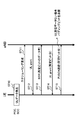
- An example of the operation method of the user terminal when transmitting UL data using TCC is shown in FIG.
- uplink data (UL data) to be transmitted occurs (ST20)
- the user terminal makes a scheduling request to the radio base station (ST21). If the user terminal does not hold an individual UL resource in ST21, the user terminal activates a random access procedure.
- the radio base station transmits an UL grant that instructs resource allocation for uplink data transmission (ST22).
- the user terminal transmits a buffer status report (BSR) indicating the UL data amount to be transmitted based on the UL grant (ST23).
- BSR buffer status report
- the radio base station that has received the BSR notifies the user terminal of an UL grant indicating the TCC uplink resource allocation for a predetermined bit (ST24), and the user terminal uses the allocated TCC PUSCH within the limited number of bits.
- UL data can be transmitted (ST25).
- the user terminal When the user terminal that has received the UL grant from the radio base station in ST24 has a situation in which there is no data to be transmitted in ST25, the user terminal performs control so as not to perform UL transmission (padding bit transmission) in TCC in ST25. be able to.
- the user terminal that has received the UL grant from the radio base station in ST24 has a UL data amount to be transmitted in ST25 that is equal to or smaller than a predetermined value
- the user terminal performs UL transmission in TCC (a lot of padding bits occupy in ST25). It may be controlled not to perform (UL transmission).
- the predetermined value may be a predetermined value or a value set for the user terminal in an upper layer such as RRC signaling.
- a predetermined value is provided for the ratio of the UL resource allocation amount and the UL data amount to control the presence or absence of UL transmission in the TCC. Good. For example, when the UL data amount to be actually transmitted is less than 1% with respect to the allocated UL resource amount, the user terminal can operate so as not to perform the UL transmission in TCC.
- the user terminal may notify the radio base station that there is no transmission data corresponding to the UL grant (ST26).
- the user terminal can perform information indicating that there is no transmission data corresponding to the UL grant using the PCC and / or the SCC UL (for example, PUSCH).
- a 2nd aspect demonstrates UL HARQ operation
- the user terminal applies the synchronous UL HARQ based on the PHICH (Physical Hybrid-ARQ Indicator Channel) notified from the radio base station.
- PHICH Physical Hybrid-ARQ Indicator Channel
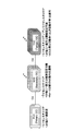
- FIG. 9 shows a case where the user terminal transmits UL data (for example, PUSHC) in subframe # 0.
- the radio base station determines whether or not the UL data (PUSCH) transmitted from the user terminal has been properly received, and transmits a retransmission control PHICH (ACK / NACK) to the user terminal after a predetermined timing.
- the radio base station can set the timing of transmitting PHICH, for example, after 4 subframes (here, subframe # 4) in FDD.
- the user terminal transmits new UL data when the PHICH transmitted from the radio base station is ACK, and performs retransmission control of the UL data when the PHICH is NACK.
- the user terminal When retransmitting UL data, the user terminal retransmits UL data after a predetermined timing after receiving PHICH.
- the user terminal can set a predetermined timing after 4 subframes (here, subframe # 8) in FDD.
- the user terminal and the radio base station control UL data retransmission control (UL HARQ) at a predetermined timing (synchronous HARQ). Also in TDD, the user terminal and the radio base station can control UL data retransmission control (UL HARQ) at a predetermined timing (synchronous HARQ).
- the user terminal may not be able to perform UL retransmission at a predetermined timing depending on the LBT result. For example, when the user terminal retransmits UL data based on PHICH (NACK), when transmission is restricted based on the LBT result performed before resending UL data (channel is busy (LBT_busy)), UL data cannot be retransmitted at a predetermined timing. Therefore, in an unlicensed band (for example, TCC), it becomes difficult for a user terminal to apply synchronous HARQ like PCC and SCC of the existing system.
- NACK PHICH
- LBT_busy channel is busy
- the user terminal applies asynchronous HARQ in TCC.
- the user terminal can operate without reading (without detecting) ACK / NACK for PHICH (synchronous HARQ operation) (see FIG. 10).
- HARQ operation synchronous HARQ operation
- the user terminal does not read PHICH Can operate with (not detected).
- FIG. 10 shows a case where the user terminal transmits UL data (for example, PUSHC) in subframe # 0 in TCC.
- the radio base station determines whether or not UL data (PUSCH) transmitted from the user terminal has been properly received, and notifies that when retransmission control is necessary.
- UL grant using the PDCCH of the TCC or UL grant (cross-carrier scheduling) using PUCCH of another CC (PCC or SCC) can be used.
- the radio base station transmits a UL grant for retransmission control to the user terminal at a predetermined timing.
- the predetermined timing may be four subframes before the subframe to which retransmission of UL data is allocated (subframe # 6 in FIG. 10), or may be other timing.
- the user terminal controls retransmission of UL data based on the UL grant, not the PHICH transmitted from the radio base station. In this case, the user terminal can perform LBT after receiving the UL grant, and can control the transmission timing of UL data according to the result of the LBT (asynchronous UL HARQ).
- the user terminal can perform LBT in the TCC after receiving the UL grant, and can retransmit the UL data in the earliest subframe (subframe # 10 in FIG. 10) that can be transmitted (LBT_idle). .
- the user terminal can control retransmission of UL data according to UL grant and LBT result in TCC (asynchronous UL HARQ).
- TCC asynchronous UL HARQ
- FIG. 10 shows the case where TCC is FDD, asynchronous UL HARQ can be applied even when TCC is TDD.
- a HARQ process number may be assigned to the UL grant for asynchronous HARQ.
- the HARQ process number indicates a number for a HARQ process (HARQ process) for one transport block (TB).
- the radio base station can include the HARQ process number corresponding to UL data # 0 in the UL grant and transmit it to the user terminal.
- the bit field for HPN set in the UL grant can be, for example, 3 bits. In the case of 3 bits, a maximum of 8 HARQ process numbers are designated, and each HARQ process can be performed in parallel. Also, by including information on UL data to be retransmitted (here, the HARQ process number) in the UL grant, the user terminal can appropriately grasp the UL data to be retransmitted.
- the UL HARQ operation method of the user terminal in which TCC is set will be specifically described.
- this Embodiment is not restricted to this.
- the present invention can be similarly applied to a case where a PDCCH trigger is performed from PCC and / or SCC to TCC at the time of non-collision type random access (CFRA: Contention Free Random Access).
- CFRA non-collision type random access
- Method 1 When the user terminal is instructed to transmit UL of the TCC from the PCC and / or SCC (eg, using the PUCCH), the user terminal operates so as not to read (not detect) the PHICH corresponding to the PUSCH scheduled for the TCC. can do. On the other hand, the user terminal can detect the PHICH corresponding to the PUSCH scheduled for the PCC and / or the SCC in the same manner as the existing system, and can control retransmission control.
- the radio base station can add information (for example, 3 bits) on the HARQ process number to the UL grant scheduled in the TCC.
- the UL grant scheduled for the PCC and / or SCC may be configured not to add information related to the HARQ process number.
- the user terminal applies synchronous HARQ using PHICH in PCC and / or SCC, and applies asynchronous HARQ in TCC.
- PCC and / or SCC the increase in the information amount of UL grant can be suppressed and PDCCH overhead can be reduced.
- the user terminal can operate so as not to read (not detect) the PHICH corresponding to the PUSCH scheduled for the TCC when the UL transmission of the TCC is instructed from the PCC and / or the SCC. Similarly, the user terminal may operate so as not to read (not detect) PHICH corresponding to PUSCH scheduled to PCC and / or SCC.
- the radio base station can add information (for example, 3 bits) on the HARQ process number to the UL grant scheduled for the PCC, SCC, and TCC.
- the search space can be shared. That is, the user terminal can detect downlink control information for PCC, SCC, and TCC at a time in blind decoding for downlink control information (for example, UL grant).
- a predetermined bit value (for example, a fixed value of 0) is set when scheduling for CCs other than the TCC (PCC and / or SCC). It may be set.
- the user terminal Based on the HARQ process number (for example, a fixed value) included in the UL grant of the PCC and / or the SCC, the user terminal can perform retransmission control at a predetermined timing, as in the case of using PHICH.
- TCC is an unlicensed band
- the radio base station eNB
- assigns UL transmission for example, PUSCH
- the LBT result of the TCC is (LBT_busy)
- the UL transmission of the user terminal is restricted. Is done.
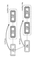
- the radio base station simultaneously allocates resources (for example, PUSCH resources, PUCCH resources, etc.) from one CC to a plurality of TCCs. That is, when instructed to transmit UL in TCC, the user terminal can perform UL transmission using TCC (LBT_idle) that can be transmitted among a plurality of TCCs.
- resources for example, PUSCH resources, PUCCH resources, etc.
- the radio base station can associate CCs with user terminals in advance. For example, as shown in FIG. 11, a TCC group # 1 including a plurality of TCC # 1 and # 2 (CC # 2, # 3) is associated with the PCC (CC # 1). Alternatively, the TCC group # 2 including a plurality of TCC # 3 and # 4 (CC # 5, # 6) is associated with the SCC (CC # 4). The association information between CCs can be notified from the radio base station to the user terminal.
- the radio base station transmits UL signal allocation information (for example, UL grant) to the TCC group # 1 from the PCC (CC # 1) to the user terminal.
- UL signal allocation information for example, UL grant
- the user terminal performs LBT in TCC group # 1 (multiple TCCs # 1 and # 2) associated with the PCC.
- a user terminal can perform UL transmission using TCC (LBT_idle) which can be transmitted among a plurality of TCCs.
- UL signal allocation information for example, UL grant
- the user terminal performs LBT in TCC group # 2 (a plurality of TCCs # 3 and # 4) associated with the SCC.
- a user terminal can perform UL transmission using TCC (LBT_idle) which can be transmitted among a plurality of TCCs.
- the user terminal can select a specific TCC based on a predetermined condition and perform UL transmission. For example, a user terminal selects a TCC with a small cell index (CellIndex / SCellIndex) (or a TCC with a large cell index) or a TCC with good communication quality (for example, reception quality, channel quality, etc.) and performs UL transmission. be able to.
- the user terminal may perform UL transmission using a plurality of TCCs that can be transmitted (LBT_idle). In this case, a transmission diversity effect can be obtained.
- the radio base station can perform a reception operation on a plurality of TCCs (for example, both TCC # 1 and # 2) assuming an uplink signal (PUSCH) from the user terminal. Thereby, even if the radio base station cannot grasp the result of the uplink LBT of each TCC, it is possible to appropriately receive UL data from the user terminal.
- TCCs for example, both TCC # 1 and # 2
- PUSCH uplink signal
- the user terminal transmits a power headroom (PH) indicating surplus transmission power to the radio base station for the CC (PCC and / or SCC) that performs transmission.
- PH power headroom
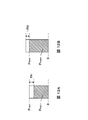
- FIG. 12 shows a conceptual diagram of the power headroom. In addition, in FIG. 12, it shows about the transmission power with respect to PUSCH.
- the user terminal when the transmission power P PUSCH of the user terminal does not reach the maximum transmission power P CMAX , the user terminal sets a value obtained by subtracting the transmission power P PUSCH from the maximum transmission power P CMAX to the surplus transmission power PH. Notify as a value. Also, as shown in FIG. 12B, when the transmission power P PUSCH of the user terminal exceeds the maximum transmission power P CMAX , the user terminal sets the value of the surplus transmission power PH with the actual transmission power as the value of the maximum transmission power P CMAX. Notifies a negative value based on the following equation (1).
- c (i) P CMAX, c (i) ⁇ ⁇ 10log 10 (M PUSCH, c (i)) + P O_PUSCH, c (j) + ⁇ c (j) ⁇ PL c + ⁇ TF, c (i) + f c (i) ⁇ (1)
- the user terminal feeds back a PHR (Power Headroom Report) for reporting the surplus transmission power of the user terminal to the radio base station.
- the PHR includes PH that is difference information between the transmission power P PUSCH of the user terminal and the maximum transmission power P CMAX and a 2-bit reserved area.
- Type 1 and Type 2 are supported for PH, Type 1 PH is a PH when only PUSCH is transmitted, and Type 2 PH is assumed to transmit PUSCH and PUCCH. It is PH of the case.
- the user terminal reports information on real PHR (Real PHR) in consideration of actual transmission power for CCs that perform UL transmission, and information on virtual PHR (Virtual PHR) for CCs that do not perform UL transmission.
- Real PHR real PHR
- Virtual PHR Virtual PHR
- a virtual PH (VPH) corresponds to a PH that does not depend on the PUSCH bandwidth
- a PHR including the virtual PH is also referred to as a virtual PHR.
- the user terminal reports information related to the real PHR and the virtual PHR to the radio base station using the PU PU of the CC that performs UL transmission by being included in the MAC CE.
- the radio base station can take into account the total surplus transmission power including uplink transmission power control of CCs that do not transmit by receiving information on the virtual PHR in addition to the real PHR.
- the user terminal reports a virtual PHR to a TCC whose transmission is restricted by the LBT result even if UL transmission is allocated in the TCC.
- the virtual PHR is reported from the user terminal for the TCC on the radio base station side, it is difficult to grasp accurate UL transmission power.
- the user terminal when the user terminal performs LBT immediately before UL transmission, the LBT result may be found immediately before UL transmission. Therefore, the user terminal needs to create a virtual PHR if the LBT result is LBT_busy even if the MAC CE is created using information related to the real PHR in order to perform UL transmission in the TCC. In such a case, there is a possibility that the change of information transmitted by the user terminal (real PHR ⁇ virtual PHR) may not be in time.
- the user terminal can be controlled to transmit information on a predetermined PHR regardless of the LBT result of UL transmission in TCC.
- the user terminal can appropriately generate and transmit information on PHR.
- the user terminal may notify the radio base station in advance of information relating to the type of information relating to the PHR to be generated / transmitted (for example, real PHR or virtual PHR). Or you may set the kind of PHR which a wireless base station transmits to a user terminal previously.
- the user terminal can report the real PHR to the TCC even when UL transmission in the TCC is restricted (LBT_busy).
- LBT_busy since the UL signal is assigned in the TCC from the radio base station to the user terminal, the user terminal can calculate and report the real PHR.
- the user terminal can perform real PHR reporting to the TCC in another CC (for example, PCC and / or SCC) that enables UL transmission.
- the user terminal can determine the type of PHR to be reported based on whether a UL signal is assigned and generate PHR (generate MAC CE), thereby reducing the burden on the user terminal. It becomes possible.
- the user terminal may be configured to always report the virtual PHR for TCC, or may be configured to select the type of PHR reported by the user terminal (real PHR / virtual PHR).
- FIG. 13 is a diagram illustrating an example of a schematic configuration of a wireless communication system according to an embodiment of the present invention.
- the radio communication system shown in FIG. 13 is a system including, for example, an LTE system, SUPER 3G, LTE-A system, and the like.
- carrier aggregation (CA) and / or dual connectivity (DC) in which a plurality of component carriers (PCC, SCC, TCC) are integrated can be applied.
- This wireless communication system may be called IMT-Advanced, or may be called 4G, 5G, FRA (Future Radio Access), or the like.
- the radio communication system 1 shown in FIG. 13 includes a radio base station 11 that forms a macro cell C1, and radio base stations 12a-12c that are arranged in the macro cell C1 and form a small cell C2 that is narrower than the macro cell C1. . Moreover, the user terminal 20 is arrange
- the user terminal 20 can be connected to both the radio base station 11 and the radio base station 12. It is assumed that the user terminal 20 uses the macro cell C1 and the small cell C2 that use different frequencies simultaneously by CA or DC. Further, the user terminal 20 can apply CA or DC using at least six or more CCs (cells). As an example, the macro cell C1 can be set as a PCell (PCC) and the small cell C2 as a SCell (SCC) and / or a TCell (TCC) in a user terminal. In addition, a license band and / or an unlicensed band can be set as the TCC.
- PCC PCell
- SCC SCell
- TCC TCell
- a license band and / or an unlicensed band can be set as the TCC.
- Communication between the user terminal 20 and the radio base station 11 can be performed using a carrier having a relatively low frequency band (for example, 2 GHz) and a narrow bandwidth (referred to as an existing carrier or a legacy carrier).
- a carrier having a relatively high frequency band for example, 3.5 GHz, 5 GHz, etc.
- a wide bandwidth may be used between the user terminal 20 and the radio base station 12, or The same carrier may be used.
- a wired connection optical fiber, X2 interface, etc.
- a wireless connection may be employed between the wireless base station 11 and the wireless base station 12 (or between the two wireless base stations 12).
- the radio base station 11 and each radio base station 12 are connected to the higher station apparatus 30 and connected to the core network 40 via the higher station apparatus 30.
- the upper station device 30 includes, for example, an access gateway device, a radio network controller (RNC), a mobility management entity (MME), and the like, but is not limited thereto.
- RNC radio network controller
- MME mobility management entity
- Each radio base station 12 may be connected to the higher station apparatus 30 via the radio base station 11.
- the radio base station 11 is a radio base station having a relatively wide coverage, and may be called a macro base station, an aggregation node, an eNB (eNodeB), a transmission / reception point, or the like.
- the radio base station 12 is a radio base station having local coverage, and includes a small base station, a micro base station, a pico base station, a femto base station, a HeNB (Home eNodeB), an RRH (Remote Radio Head), and transmission / reception. It may be called a point.
- the radio base stations 11 and 12 are not distinguished, they are collectively referred to as a radio base station 10.
- Each user terminal 20 is a terminal that supports various communication schemes such as LTE and LTE-A, and may include not only a mobile communication terminal but also a fixed communication terminal.
- OFDMA Orthogonal Frequency Division Multiple Access
- SC-FDMA Single Carrier Frequency Division Multiple Access
- OFDMA is a multi-carrier transmission scheme that performs communication by dividing a frequency band into a plurality of narrow frequency bands (subcarriers) and mapping data to each subcarrier.
- SC-FDMA is a single-carrier transmission scheme that reduces interference between terminals by dividing the system bandwidth into bands consisting of one or continuous resource blocks for each terminal and using a plurality of terminals with mutually different bands. is there.
- the uplink and downlink radio access methods are not limited to these combinations.
- downlink channels include a downlink shared channel (PDSCH) shared by each user terminal 20, a broadcast channel (PBCH: Physical Broadcast Channel), a downlink L1 / L2 control channel, and the like. Used. User data, higher layer control information, and predetermined SIB (System Information Block) are transmitted by PDSCH. Moreover, MIB (Master Information Block) etc. are transmitted by PBCH.
- PDSCH downlink shared channel
- PBCH Physical Broadcast Channel
- SIB System Information Block
- MIB Master Information Block
- Downlink L1 / L2 control channels include PDCCH (Physical Downlink Control Channel), EPDCCH (Enhanced Physical Downlink Control Channel), PCFICH (Physical Control Format Indicator Channel), PHICH (Physical Hybrid-ARQ Indicator Channel), and the like.
- Downlink control information (DCI: Downlink Control Information) including scheduling information of PDSCH and PUSCH is transmitted by PDCCH.
- the number of OFDM symbols used for PDCCH is transmitted by PCFICH.
- the HAICH transmission confirmation signal (ACK / NACK) for PUSCH is transmitted by PHICH.
- the EPDCCH is frequency division multiplexed with a PDSCH (downlink shared data channel) and may be used to transmit DCI or the like in the same manner as the PDCCH.
- a downlink reference signal a cell-specific reference signal (CRS), a channel state measurement reference signal (CSI-RS), a user-specific reference signal used for demodulation includes reference signals (DM-RS: Demodulation Reference Signal).
- CRS cell-specific reference signal
- CSI-RS channel state measurement reference signal
- DM-RS Demodulation Reference Signal
- an uplink shared channel (PUSCH: Physical Uplink Shared Channel), an uplink control channel (PUCCH: Physical Uplink Control Channel), and a random access channel (PRACH) shared by each user terminal 20 are used. Physical Random Access Channel) is used. User data and higher layer control information are transmitted by PUSCH. Also, downlink radio quality information (CQI: Channel Quality Indicator), a delivery confirmation signal (HARQ-ACK), and the like are transmitted by PUCCH.
- CQI Channel Quality Indicator
- HARQ-ACK delivery confirmation signal
- a random access preamble (RA preamble) for establishing a connection with the cell is transmitted by the PRACH.
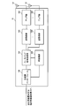
- FIG. 14 is a diagram illustrating an example of the overall configuration of a radio base station according to an embodiment of the present invention.
- the radio base station 10 includes a plurality of transmission / reception antennas 101, an amplifier unit 102, a transmission / reception unit 103, a baseband signal processing unit 104, a call processing unit 105, and a transmission path interface 106.
- the transmission / reception unit 103 includes a transmission unit and a reception unit.
- User data transmitted from the radio base station 10 to the user terminal 20 via the downlink is input from the higher station apparatus 30 to the baseband signal processing unit 104 via the transmission path interface 106.
- PDCP Packet Data Convergence Protocol
- RLC Radio Link Control
- MAC Medium Access
- Retransmission control for example, transmission processing of HARQ (Hybrid Automatic Repeat reQuest)
- HARQ Hybrid Automatic Repeat reQuest
- IFFT inverse Fast Fourier Transform
- precoding processing etc.
- the downlink control signal is also subjected to transmission processing such as channel coding and inverse fast Fourier transform, and transferred to each transmitting / receiving unit 103.
- Each transmission / reception unit 103 converts the baseband signal output by precoding from the baseband signal processing unit 104 for each antenna to a radio frequency band and transmits the converted signal.
- the radio frequency signal frequency-converted by the transmission / reception unit 103 is amplified by the amplifier unit 102 and transmitted from the transmission / reception antenna 101.
- the transmission / reception unit 103 can transmit information related to a CC performing CA (for example, information on a cell serving as a TCC).
- the transmission / reception unit 103 can transmit downlink control information (for example, UL grant) instructing UL transmission in TCC.
- the transceiver 103 may transmit a UL grant for the TCC using a TCC downlink control channel (PDCCH / EPDCCH), or may transmit using a PCC and / or SCC downlink control channel.
- Good cross carrier scheduling
- the transmission / reception unit 103 can transmit the UL grant including the HARQ process number for asynchronous HARQ to the user terminal (see FIG. 10). Moreover, the transmission / reception part 103 can transmit UL grant containing the radio
- the transmission / reception unit 103 can be a transmitter / receiver, a transmission / reception circuit, or a transmission / reception device described based on common recognition in the technical field according to the present invention.
- the radio frequency signal received by each transmitting / receiving antenna 101 is amplified by the amplifier unit 102.
- Each transmitting / receiving unit 103 receives the upstream signal amplified by the amplifier unit 102.
- the transmission / reception unit 103 converts the frequency of the received signal into a baseband signal and outputs it to the baseband signal processing unit 104.
- the baseband signal processing unit 104 performs fast Fourier transform (FFT) processing, inverse discrete Fourier transform (IDFT: Inverse Discrete Fourier Transform) processing, and error correction on user data included in the input upstream signal.
- FFT fast Fourier transform
- IDFT inverse discrete Fourier transform
- Decoding, MAC retransmission control reception processing, RLC layer, and PDCP layer reception processing are performed and transferred to the upper station apparatus 30 via the transmission path interface 106.
- the call processing unit 105 performs call processing such as communication channel setting and release, status management of the radio base station 10, and radio resource management.
- the transmission path interface 106 transmits and receives signals to and from the higher station apparatus 30 via a predetermined interface.
- the transmission path interface 106 may transmit and receive signals (backhaul signaling) to and from the adjacent radio base station 10 via an inter-base station interface (for example, an optical fiber or an X2 interface).
- FIG. 15 is a diagram illustrating an example of a functional configuration of the radio base station according to the present embodiment. Note that FIG. 15 mainly shows functional blocks of characteristic portions in the present embodiment, and the wireless base station 10 also has other functional blocks necessary for wireless communication. As shown in FIG. 15, the baseband signal processing unit 104 includes a control unit (scheduler) 301, a transmission signal generation unit (generation unit) 302, a mapping unit 303, and a reception signal processing unit 304. .
- the baseband signal processing unit 104 includes a control unit (scheduler) 301, a transmission signal generation unit (generation unit) 302, a mapping unit 303, and a reception signal processing unit 304.
- the control unit (scheduler) 301 controls scheduling (for example, resource allocation) of downlink data signals transmitted on PDSCH and downlink control signals transmitted on PDCCH and / or EPDCCH. It also controls scheduling of system information, synchronization signals, paging information, CRS, CSI-RS, and the like.
- the control unit 301 controls the transmission of the DL signal based on the result of the DL LBT for the unlicensed CC (for example, TCC).
- the control unit 301 may perform control so as to notify the user terminal of the LBT result in the license band (PCC and / or SCC).
- the control unit 301 can apply asynchronous HARQ in TCC.
- the control unit 301 can control the transmission / reception operation on the assumption that the user terminal operates without reading (without detecting) ACK / NACK for PHICH (synchronous HARQ operation).
- the control unit 301 can perform control to add a HARQ process number indicating predetermined UL data to the UL grant (see FIG. 10).
- control unit 301 can perform control so that resources from one CC (PCC and / or SCC) to a plurality of TCCs are simultaneously allocated (see FIG. 11). In this case, the control unit 301 can perform control such that association between CCs is set in advance for the user terminal, and association information between CCs is notified to the user terminal.
- control unit 301 controls scheduling of an uplink reference signal, an uplink data signal transmitted by PUSCH, an uplink control signal transmitted by PUCCH and / or PUSCH, a random access preamble transmitted by PRACH, and the like.
- the control unit 301 can be a controller, a control circuit, or a control device described based on common recognition in the technical field according to the present invention.
- the transmission signal generation unit 302 generates a DL signal based on an instruction from the control unit 301 and outputs the DL signal to the mapping unit 303. For example, based on an instruction from the control unit 301, the transmission signal generation unit 302 generates a DL assignment that notifies downlink signal allocation information and a UL grant that notifies uplink signal allocation information. Further, the downlink data signal is subjected to coding processing and modulation processing according to a coding rate, a modulation scheme, and the like determined based on channel state information (CSI) from each user terminal 20.
- the transmission signal generation unit 302 can be a signal generator, a signal generation circuit, or a signal generation device described based on common recognition in the technical field according to the present invention.
- the mapping unit 303 maps the downlink signal generated by the transmission signal generation unit 302 to a predetermined radio resource based on an instruction from the control unit 301, and outputs it to the transmission / reception unit 103.
- the mapping unit 303 can be a mapper, a mapping circuit, or a mapping device described based on common recognition in the technical field according to the present invention.
- the reception signal processing unit 304 receives UL signals (for example, a delivery confirmation signal (HARQ-ACK), a data signal transmitted on the PUSCH, a random access preamble transmitted on the PRACH, etc.) transmitted from the user terminal. Processing (for example, demapping, demodulation, decoding, etc.) is performed. The processing result is output to the control unit 301.
- UL signals for example, a delivery confirmation signal (HARQ-ACK), a data signal transmitted on the PUSCH, a random access preamble transmitted on the PRACH, etc.
- Processing for example, demapping, demodulation, decoding, etc.
- the processing result is output to the control unit 301.
- the received signal processing unit 304 may measure received power (for example, RSRP (Reference Signal Received Power)), received quality (RSRQ (Reference Signal Received Quality)), channel state, and the like using the received signal. .
- the reception signal processing unit 304 may perform DL LBT before transmitting a DL signal. Note that the measurement result in the reception signal processing unit 304 may be output to the control unit 301. Note that a measurement unit that performs a measurement operation may be provided separately from the reception signal processing unit 304.
- the reception signal processing unit 304 may be composed of a signal processor, a signal processing circuit or a signal processing device, and a measuring device, a measurement circuit or a measuring device which are described based on common recognition in the technical field according to the present invention. it can.
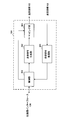
- FIG. 16 is a diagram illustrating an example of the overall configuration of the user terminal according to the present embodiment.
- the user terminal 20 includes a plurality of transmission / reception antennas 201 for MIMO transmission, an amplifier unit 202, a transmission / reception unit 203, a baseband signal processing unit 204, and an application unit 205.
- the transmission / reception unit 203 may include a transmission unit and a reception unit.
- the radio frequency signals received by the plurality of transmission / reception antennas 201 are each amplified by the amplifier unit 202.
- Each transmitting / receiving unit 203 receives the downlink signal amplified by the amplifier unit 202.
- the transmission / reception unit 203 converts the frequency of the received signal into a baseband signal and outputs it to the baseband signal processing unit 204.
- the transmission / reception unit 203 receives a DL signal such as downlink control information (for example, UL grant) instructing UL transmission in TCC.
- a DL signal such as downlink control information (for example, UL grant) instructing UL transmission in TCC.
- the transmission / reception unit 203 can receive downlink control information including a TCC UL grant from a PCC, SCC, and / or TCC downlink control channel (PDCCH / EPDCCH).
- the transmission / reception unit 203 transmits UL data using the padding bits, and determines that there is no UL data corresponding to the UL grant in the TCC. In this case, UL data can not be transmitted. In this case, the transmission / reception unit 203 may transmit information indicating that there is no UL data corresponding to the UL grant in the TCC in the UL signal of the PCC and / or SCC (see FIG. 8).
- the transmission / reception unit 203 can notify the radio base station of capability information (capability) of the user terminal. For example, the transmission / reception unit 203 transmits information related to TCCs that can be set simultaneously (for example, TCC combination information) to the radio base station in addition to information related to frequencies that can use TCC.
- the transmission / reception unit 203 can be a transmitter / receiver, a transmission / reception circuit, or a transmission / reception device described based on common recognition in the technical field according to the present invention.
- the baseband signal processing unit 204 performs FFT processing, error correction decoding, retransmission control reception processing, and the like on the input baseband signal.
- the downlink user data is transferred to the application unit 205.
- the application unit 205 performs processing related to layers higher than the physical layer and the MAC layer.
- broadcast information in the downlink data is also transferred to the application unit 205.
- uplink user data is input from the application unit 205 to the baseband signal processing unit 204.
- the baseband signal processing unit 204 performs retransmission control transmission processing (for example, HARQ transmission processing), channel coding, precoding, discrete Fourier transform (DFT) processing, IFFT processing, and the like.
- the data is transferred to the transmission / reception unit 203.
- the transmission / reception unit 203 converts the baseband signal output from the baseband signal processing unit 204 into a radio frequency band and transmits it.
- the radio frequency signal frequency-converted by the transmission / reception unit 203 is amplified by the amplifier unit 202 and transmitted from the transmission / reception antenna 201.
- FIG. 17 is a diagram illustrating an example of a functional configuration of the user terminal according to the present embodiment. Note that FIG. 17 mainly shows functional blocks of characteristic portions in the present embodiment, and the user terminal 20 also has other functional blocks necessary for wireless communication. As illustrated in FIG. 17, the baseband signal processing unit 204 included in the user terminal 20 includes a control unit 401, a transmission signal generation unit 402, a mapping unit 403, and a reception signal processing unit 404.
- the control unit 401 obtains, from the received signal processing unit 404, a downlink control signal (a signal transmitted by PDCCH / EPDCCH) and a downlink data signal (a signal transmitted by PDSCH) transmitted from the radio base station 10.
- the control unit 401 controls generation of an uplink control signal (for example, a delivery confirmation signal) and an uplink data signal based on a downlink control signal, a result of determining whether or not retransmission control is required for the downlink data signal, and the like.
- the control unit 401 can control the transmission signal generation unit 402, the mapping unit 403, and the reception signal processing unit 404.
- the control unit 401 can also control the transmission / reception unit 203.
- the control unit 401 may apply a UL signal transmission operation different from PCC and / or SCC to TCC. it can.
- control unit 401 determines that there is no UL data corresponding to the UL grant in the PCC or the SCC, the control unit 401 performs control so that UL data is transmitted using a padding bit. Further, the control unit 401 can perform control so as not to transmit UL data when it is determined that there is no UL data corresponding to the UL grant in the TCC (see FIG. 8).
- control unit 401 can apply asynchronous HARQ to the UL signal transmitted in the TCC (see FIG. 10).
- the control unit 401 can perform control so that the PHICH is not detected in the TCC when the transmission / reception unit 203 receives a UL grant that instructs transmission of a UL signal in the TCC.
- control unit 401 can perform retransmission control on the UL signal transmitted in the TCC based on the HARQ process number included in the UL grant.
- the control unit 401 performs listening for a plurality of TCCs set in advance, and the UL signal is transmitted at a predetermined TCC based on the listening result. Can be transmitted (see FIG. 11).
- control unit 401 can control to report a predetermined PHR (for example, real PHR) to the radio base station as a TCC PHR (Power Headroom Report) regardless of the listening result.
- a predetermined PHR for example, real PHR
- TCC PHR Power Headroom Report
- the control unit 401 can be a controller, a control circuit, or a control device described based on common recognition in the technical field according to the present invention.
- the transmission signal generation unit 402 generates a UL signal based on an instruction from the control unit 401 and outputs the UL signal to the mapping unit 403. For example, the transmission signal generation unit 402 generates an uplink control signal such as a delivery confirmation signal (HARQ-ACK) or channel state information (CSI) based on an instruction from the control unit 401.
- HARQ-ACK delivery confirmation signal
- CSI channel state information
- the transmission signal generation unit 402 generates an uplink data signal based on an instruction from the control unit 401.
- the transmission signal generation unit 402 can operate so as not to generate UL data (padding bits) when it is determined that there is no UL data corresponding to the UL grant in the TCC.
- the transmission signal generation unit 402 generates an uplink data signal for retransmission based on an instruction from the control unit 401 (such as a HARQ process number included in the UL grant).
- the transmission signal generation unit 402 may be a signal generator, a signal generation circuit, or a signal generation device described based on common recognition in the technical field according to the present invention.
- the mapping unit 403 maps the uplink signal (uplink control signal and / or uplink data) generated by the transmission signal generation unit 402 to a radio resource based on an instruction from the control unit 401, and outputs the radio resource to the transmission / reception unit 203.
- the mapping unit 403 may be a mapper, a mapping circuit, or a mapping device described based on common recognition in the technical field according to the present invention.
- the reception signal processing unit 404 performs reception processing (for example, demapping and demodulation) on a DL signal (for example, a downlink control signal transmitted from a radio base station using PDCCH / EPDCCH, a downlink data signal transmitted using PDSCH, etc.). , Decryption, etc.).
- the reception signal processing unit 404 outputs information received from the radio base station 10 to the control unit 401.
- the reception signal processing unit 404 outputs broadcast information, system information, RRC signaling, DCI, and the like to the control unit 401, for example.
- the reception signal processing unit 404 can control the reception operation of the DL signal based on an instruction from the control unit 401. For example, when applying asynchronous UL HARQ in TCC, received signal processing section 404 operates so as not to detect PHICH in TCC when receiving UL grant instructing transmission of UL signal in TCC. Can do.
- the received signal processing unit 404 may measure received power (for example, RSRP (Reference Signal Received Power)), received quality (RSRQ (Reference Signal Received Quality)), channel state, and the like using the received signal. .
- the reception signal processing unit 404 may perform UL LBT before transmitting a UL signal.
- the measurement result in the reception signal processing unit 404 may be output to the control unit 401. Note that a measurement unit that performs a measurement operation may be provided separately from the reception signal processing unit 404.
- the reception signal processing unit 404 may be configured by a signal processor, a signal processing circuit or a signal processing device, and a measuring device, a measurement circuit or a measuring device which are described based on common recognition in the technical field according to the present invention. it can.
- each functional block is realized by one physically coupled device, or may be realized by two or more physically separated devices connected by wire or wirelessly and by a plurality of these devices. Good.
- radio base station 10 and the user terminal 20 are realized using hardware such as ASIC (Application Specific Integrated Circuit), PLD (Programmable Logic Device), and FPGA (Field Programmable Gate Array). May be.
- the radio base station 10 and the user terminal 20 may be realized by a computer apparatus including a processor (CPU), a communication interface for network connection, a memory, and a computer-readable storage medium holding a program. Good.
- the processor and memory are connected by a bus for communicating information.
- the computer-readable recording medium is a storage medium such as a flexible disk, a magneto-optical disk, a ROM, an EPROM, a CD-ROM, a RAM, and a hard disk.
- the program may be transmitted from a network via a telecommunication line.
- the radio base station 10 and the user terminal 20 may include an input device such as an input key and an output device such as a display.
- the functional configurations of the radio base station 10 and the user terminal 20 may be realized by the hardware described above, may be realized by a software module executed by a processor, or may be realized by a combination of both.
- the processor controls the entire user terminal by operating an operating system. Further, the processor reads programs, software modules and data from the storage medium into the memory, and executes various processes according to these.
- the program may be a program that causes a computer to execute the operations described in the above embodiments.
- the control unit 401 of the user terminal 20 may be realized by a control program stored in a memory and operated by a processor, and may be realized similarly for other functional blocks.
Abstract
Priority Applications (6)
| Application Number | Priority Date | Filing Date | Title |
|---|---|---|---|
| US15/548,460 US10512067B2 (en) | 2015-02-19 | 2016-02-19 | User terminal, radio base station, and radio communication method |
| SG11201706410XA SG11201706410XA (en) | 2015-02-19 | 2016-02-19 | User terminal, wireless base station and wireless communication method |
| EP16752569.0A EP3261402A4 (fr) | 2015-02-19 | 2016-02-19 | Terminal utilisateur, station de base sans fil et procédé de communication sans fil |
| JP2017500744A JP6408122B2 (ja) | 2015-02-19 | 2016-02-19 | ユーザ端末、無線基地局及び無線通信方法 |
| CN201680010952.9A CN107409411B (zh) | 2015-02-19 | 2016-02-19 | 用户终端、无线基站以及无线通信方法 |
| US16/681,197 US20200084763A1 (en) | 2015-02-19 | 2019-11-12 | Terminal and radio control method |
Applications Claiming Priority (2)
| Application Number | Priority Date | Filing Date | Title |
|---|---|---|---|
| JP2015-030785 | 2015-02-19 | ||
| JP2015030785 | 2015-02-19 |
Related Child Applications (2)
| Application Number | Title | Priority Date | Filing Date |
|---|---|---|---|
| US15/548,460 A-371-Of-International US10512067B2 (en) | 2015-02-19 | 2016-02-19 | User terminal, radio base station, and radio communication method |
| US16/681,197 Continuation US20200084763A1 (en) | 2015-02-19 | 2019-11-12 | Terminal and radio control method |
Publications (1)
| Publication Number | Publication Date |
|---|---|
| WO2016133183A1 true WO2016133183A1 (fr) | 2016-08-25 |
Family
ID=56689403
Family Applications (1)
| Application Number | Title | Priority Date | Filing Date |
|---|---|---|---|
| PCT/JP2016/054785 WO2016133183A1 (fr) | 2015-02-19 | 2016-02-19 | Terminal utilisateur, station de base sans fil et procédé de communication sans fil |
Country Status (6)
| Country | Link |
|---|---|
| US (2) | US10512067B2 (fr) |
| EP (1) | EP3261402A4 (fr) |
| JP (1) | JP6408122B2 (fr) |
| CN (1) | CN107409411B (fr) |
| SG (1) | SG11201706410XA (fr) |
| WO (1) | WO2016133183A1 (fr) |
Cited By (2)
| Publication number | Priority date | Publication date | Assignee | Title |
|---|---|---|---|---|
| JP2018513614A (ja) * | 2015-04-09 | 2018-05-24 | エルジー エレクトロニクス インコーポレイティド | 非兔許スペクトルで動作する少なくとも一つのSCellを有する搬送波集成において電力ヘッドルーム報告を送信するための方法及びそのための装置 |
| JP2018113689A (ja) * | 2017-01-13 | 2018-07-19 | 華碩電腦股▲ふん▼有限公司 | 無線通信システムにおける制御チャネルとデータチャネルとのタイミング関係についての方法及び装置 |
Families Citing this family (10)
| Publication number | Priority date | Publication date | Assignee | Title |
|---|---|---|---|---|
| CN107431580B (zh) * | 2015-05-15 | 2020-07-14 | 华为技术有限公司 | 授权辅助接入系统中用于传输上行数据的方法和装置 |
| US10334624B2 (en) * | 2016-04-29 | 2019-06-25 | Ofinno, Llc | Allocation of licensed assisted access resources in a wireless device |
| US10517021B2 (en) | 2016-06-30 | 2019-12-24 | Evolve Cellular Inc. | Long term evolution-primary WiFi (LTE-PW) |
| EP3799503A1 (fr) | 2016-11-05 | 2021-03-31 | Apple Inc. | Prise en charge de largeur de bande asymétrique et réglage de largeur de bande dynamique |
| CN108811145A (zh) * | 2017-05-04 | 2018-11-13 | 株式会社Ntt都科摩 | 发送和接收上行数据的方法、用户设备和基站 |
| US10631195B2 (en) * | 2017-06-16 | 2020-04-21 | Hughes Network Systems, Llc | Buffer status report trigger enhancement in a long term evolution and satellite communication system |
| WO2019095265A1 (fr) | 2017-11-17 | 2019-05-23 | Telefonaktiebolaget Lm Ericsson (Publ) | Dispositif et procédé de traitement de signal dans un système radio à accès assisté sous licence |
| CN110149684B (zh) * | 2018-02-11 | 2021-02-19 | 维沃移动通信有限公司 | 无线通信方法、终端设备和网络设备 |
| CN111225447B (zh) * | 2018-11-23 | 2023-04-07 | 奇酷互联网络科技(深圳)有限公司 | 一种数据时延优化方法和移动终端 |
| CN112637894B (zh) * | 2020-12-18 | 2023-08-01 | 京信网络系统股份有限公司 | 资源配置方法、装置、接入网设备和存储介质 |
Family Cites Families (12)
| Publication number | Priority date | Publication date | Assignee | Title |
|---|---|---|---|---|
| EP2424139A4 (fr) * | 2009-04-24 | 2016-05-18 | Lg Electronics Inc | Procédé et appareil pour transmettre et recevoir un signal de commande pour fusionner des porteuses lors d'une transmission |
| CN101925105B (zh) * | 2009-06-15 | 2013-04-03 | 电信科学技术研究院 | 一种上报上行功率余量信息的方法及装置 |
| US8594718B2 (en) * | 2010-06-18 | 2013-11-26 | Intel Corporation | Uplink power headroom calculation and reporting for OFDMA carrier aggregation communication system |
| KR101832175B1 (ko) * | 2010-10-12 | 2018-02-27 | 삼성전자주식회사 | 캐리어 집적을 위한 이동통신 시스템에서 캐리어 별 최대 송신 전력을 결정하는 방법 및 장치 |
| TWI615043B (zh) | 2011-02-07 | 2018-02-11 | 內數位專利控股公司 | 在免頻譜執照中操作補充胞元方法及裝置 |
| GB2498988B (en) * | 2012-02-02 | 2014-08-06 | Broadcom Corp | Communications apparatus and methods |
| US8885752B2 (en) * | 2012-07-27 | 2014-11-11 | Intel Corporation | Method and apparatus for feedback in 3D MIMO wireless systems |
| WO2015069065A1 (fr) * | 2013-11-07 | 2015-05-14 | 엘지전자 주식회사 | Procédé d'émission/réception de signal de liaison descendante dans un système de communication sans fil et appareil associé |
| CN106134263B (zh) * | 2014-01-29 | 2019-11-08 | 交互数字专利控股公司 | 无线通信中的上行链路传输 |
| WO2015174759A1 (fr) * | 2014-05-15 | 2015-11-19 | 엘지전자 주식회사 | Régulation de la puissance dans une bande sans licence |
| CN117278181A (zh) * | 2015-01-28 | 2023-12-22 | 交互数字专利控股公司 | 无线发射/接收单元(wtru)及方法 |
| WO2016126189A1 (fr) * | 2015-02-02 | 2016-08-11 | Telefonaktiebolaget Lm Ericsson (Publ) | Recherche de cellule pour équipements utilisateurs compatibles avec d2d hors couverture réseau |
-
2016
- 2016-02-19 JP JP2017500744A patent/JP6408122B2/ja active Active
- 2016-02-19 WO PCT/JP2016/054785 patent/WO2016133183A1/fr active Application Filing
- 2016-02-19 SG SG11201706410XA patent/SG11201706410XA/en unknown
- 2016-02-19 US US15/548,460 patent/US10512067B2/en active Active
- 2016-02-19 CN CN201680010952.9A patent/CN107409411B/zh active Active
- 2016-02-19 EP EP16752569.0A patent/EP3261402A4/fr not_active Withdrawn
-
2019
- 2019-11-12 US US16/681,197 patent/US20200084763A1/en not_active Abandoned
Non-Patent Citations (4)
| Title |
|---|
| ERICSSON: "Discussion on UL HARQ handling in LAA", 3GPP TSG-RAN WG1#80 R1-150583, 13 February 2015 (2015-02-13), XP050948764, Retrieved from the Internet <URL:http://www.3gpp.org/ftp/tsg_ran/WG1_RL1/TSGR1_80/Docs/Rl-150583.zip> [retrieved on 20160303] * |
| INTEL CORPORATION: "On the LAA uplink: scheduling, LBT, and HARQ", 3GPP TSG-RAN WG1#80 R1-150507, 13 February 2015 (2015-02-13), XP050949030, Retrieved from the Internet <URL:http://www.3gpp.org/ftp/tsg_ran/WG1_RL1/TSGR1_80/Docs/R1-150507.zip> [retrieved on 20160303] * |
| MICROSOFT CORPORATION: "Discussion on DL and UL transmissions for licensed-assisted access using LTE", 3GPP TSG-RAN WG1#80 R1-150631, 13 February 2015 (2015-02-13), XP050948716, Retrieved from the Internet <URL:http://www.3gpp.org/ftp/tsg-ran/WG1_RL1/TSGR1_80/Docs/R1-150631.zip> [retrieved on 20160303] * |
| See also references of EP3261402A4 * |
Cited By (6)
| Publication number | Priority date | Publication date | Assignee | Title |
|---|---|---|---|---|
| JP2018513614A (ja) * | 2015-04-09 | 2018-05-24 | エルジー エレクトロニクス インコーポレイティド | 非兔許スペクトルで動作する少なくとも一つのSCellを有する搬送波集成において電力ヘッドルーム報告を送信するための方法及びそのための装置 |
| US10531404B2 (en) | 2015-04-09 | 2020-01-07 | Lg Electronics Inc. | Method for transmitting a power headroom reporting in a carrier aggregation with at least one SCell operating in an unlicensed spectrum and a device therefor |
| JP2018113689A (ja) * | 2017-01-13 | 2018-07-19 | 華碩電腦股▲ふん▼有限公司 | 無線通信システムにおける制御チャネルとデータチャネルとのタイミング関係についての方法及び装置 |
| KR20180083819A (ko) * | 2017-01-13 | 2018-07-23 | 아서스테크 컴퓨터 인코포레이션 | 무선 통신 시스템에서의 제어 채널 및 데이터 채널 간 타이밍 관계를 위한 방법 및 장치 |
| US10356808B2 (en) | 2017-01-13 | 2019-07-16 | Asustek Computer Inc. | Method and apparatus for timing relationship between control channel and data channel in a wireless communication system |
| KR102101546B1 (ko) | 2017-01-13 | 2020-04-17 | 아서스테크 컴퓨터 인코포레이션 | 무선 통신 시스템에서의 제어 채널 및 데이터 채널 간 타이밍 관계를 위한 방법 및 장치 |
Also Published As
| Publication number | Publication date |
|---|---|
| EP3261402A4 (fr) | 2018-09-26 |
| SG11201706410XA (en) | 2017-09-28 |
| CN107409411B (zh) | 2021-02-19 |
| US20180020445A1 (en) | 2018-01-18 |
| EP3261402A1 (fr) | 2017-12-27 |
| US10512067B2 (en) | 2019-12-17 |
| JP6408122B2 (ja) | 2018-10-17 |
| US20200084763A1 (en) | 2020-03-12 |
| CN107409411A (zh) | 2017-11-28 |
| JPWO2016133183A1 (ja) | 2018-01-18 |
Similar Documents
| Publication | Publication Date | Title |
|---|---|---|
| JP6408122B2 (ja) | ユーザ端末、無線基地局及び無線通信方法 | |
| JP6609252B2 (ja) | ユーザ端末、無線基地局及び無線通信方法 | |
| JP6479963B2 (ja) | ユーザ端末、無線基地局及び無線通信方法 | |
| CN107432015B (zh) | 用户终端、无线基站以及无线通信方法 | |
| JP5948376B2 (ja) | ユーザ端末、無線基地局及び無線通信方法 | |
| JP6165201B2 (ja) | 無線基地局、ユーザ端末及び無線通信方法 | |
| WO2016006450A1 (fr) | Station de base sans fil, terminal utilisateur et système de communication sans fil | |
| US20170310434A1 (en) | User terminal, radio base station and radio communication method | |
| JP6174094B2 (ja) | ユーザ端末、無線基地局及び無線通信方法 | |
| JP2020025340A (ja) | ユーザ端末及び無線通信方法 | |
| US20190045458A1 (en) | User terminal, radio base station and radio communication method | |
| US11184123B2 (en) | Terminal and radio communication method | |
| WO2016072219A1 (fr) | Station de base sans fil, terminal utilisateur et procédé de communication sans fil |
Legal Events
| Date | Code | Title | Description |
|---|---|---|---|
| 121 | Ep: the epo has been informed by wipo that ep was designated in this application |
Ref document number: 16752569 Country of ref document: EP Kind code of ref document: A1 |
|
| WWE | Wipo information: entry into national phase |
Ref document number: 15548460 Country of ref document: US |
|
| WWE | Wipo information: entry into national phase |
Ref document number: 11201706410X Country of ref document: SG |
|
| ENP | Entry into the national phase |
Ref document number: 2017500744 Country of ref document: JP Kind code of ref document: A |
|
| NENP | Non-entry into the national phase |
Ref country code: DE |
|
| REEP | Request for entry into the european phase |
Ref document number: 2016752569 Country of ref document: EP |