WO2016133031A1 - 回転機器 - Google Patents
回転機器 Download PDFInfo
- Publication number
- WO2016133031A1 WO2016133031A1 PCT/JP2016/054220 JP2016054220W WO2016133031A1 WO 2016133031 A1 WO2016133031 A1 WO 2016133031A1 JP 2016054220 W JP2016054220 W JP 2016054220W WO 2016133031 A1 WO2016133031 A1 WO 2016133031A1
- Authority
- WO
- WIPO (PCT)
- Prior art keywords
- shaft
- bearing sleeve
- hole
- bearing
- shaped member
- Prior art date
- Legal status (The legal status is an assumption and is not a legal conclusion. Google has not performed a legal analysis and makes no representation as to the accuracy of the status listed.)
- Ceased
Links
Images

Classifications
-
- F—MECHANICAL ENGINEERING; LIGHTING; HEATING; WEAPONS; BLASTING
- F04—POSITIVE - DISPLACEMENT MACHINES FOR LIQUIDS; PUMPS FOR LIQUIDS OR ELASTIC FLUIDS
- F04D—NON-POSITIVE-DISPLACEMENT PUMPS
- F04D29/00—Details, component parts, or accessories
- F04D29/04—Shafts or bearings, or assemblies thereof
-
- F—MECHANICAL ENGINEERING; LIGHTING; HEATING; WEAPONS; BLASTING
- F04—POSITIVE - DISPLACEMENT MACHINES FOR LIQUIDS; PUMPS FOR LIQUIDS OR ELASTIC FLUIDS
- F04D—NON-POSITIVE-DISPLACEMENT PUMPS
- F04D29/00—Details, component parts, or accessories
- F04D29/04—Shafts or bearings, or assemblies thereof
- F04D29/046—Bearings
-
- F—MECHANICAL ENGINEERING; LIGHTING; HEATING; WEAPONS; BLASTING
- F16—ENGINEERING ELEMENTS AND UNITS; GENERAL MEASURES FOR PRODUCING AND MAINTAINING EFFECTIVE FUNCTIONING OF MACHINES OR INSTALLATIONS; THERMAL INSULATION IN GENERAL
- F16C—SHAFTS; FLEXIBLE SHAFTS; ELEMENTS OR CRANKSHAFT MECHANISMS; ROTARY BODIES OTHER THAN GEARING ELEMENTS; BEARINGS
- F16C17/00—Sliding-contact bearings for exclusively rotary movement
- F16C17/02—Sliding-contact bearings for exclusively rotary movement for radial load only
-
- F—MECHANICAL ENGINEERING; LIGHTING; HEATING; WEAPONS; BLASTING
- F16—ENGINEERING ELEMENTS AND UNITS; GENERAL MEASURES FOR PRODUCING AND MAINTAINING EFFECTIVE FUNCTIONING OF MACHINES OR INSTALLATIONS; THERMAL INSULATION IN GENERAL
- F16C—SHAFTS; FLEXIBLE SHAFTS; ELEMENTS OR CRANKSHAFT MECHANISMS; ROTARY BODIES OTHER THAN GEARING ELEMENTS; BEARINGS
- F16C35/00—Rigid support of bearing units; Housings, e.g. caps, covers
- F16C35/02—Rigid support of bearing units; Housings, e.g. caps, covers in the case of sliding-contact bearings
-
- F—MECHANICAL ENGINEERING; LIGHTING; HEATING; WEAPONS; BLASTING
- F16—ENGINEERING ELEMENTS AND UNITS; GENERAL MEASURES FOR PRODUCING AND MAINTAINING EFFECTIVE FUNCTIONING OF MACHINES OR INSTALLATIONS; THERMAL INSULATION IN GENERAL
- F16D—COUPLINGS FOR TRANSMITTING ROTATION; CLUTCHES; BRAKES
- F16D7/00—Slip couplings, e.g. slipping on overload, for absorbing shock
- F16D7/02—Slip couplings, e.g. slipping on overload, for absorbing shock of the friction type
-
- F—MECHANICAL ENGINEERING; LIGHTING; HEATING; WEAPONS; BLASTING
- F16—ENGINEERING ELEMENTS AND UNITS; GENERAL MEASURES FOR PRODUCING AND MAINTAINING EFFECTIVE FUNCTIONING OF MACHINES OR INSTALLATIONS; THERMAL INSULATION IN GENERAL
- F16C—SHAFTS; FLEXIBLE SHAFTS; ELEMENTS OR CRANKSHAFT MECHANISMS; ROTARY BODIES OTHER THAN GEARING ELEMENTS; BEARINGS
- F16C2360/00—Engines or pumps
- F16C2360/44—Centrifugal pumps
Definitions
- the present invention relates to a rotating device, and more particularly to a slide bearing.
- sliding bearings may be used to support the shaft.
- a bearing sleeve may be attached to the outer peripheral surface of the shaft. The bearing sleeve rotates with the shaft when the shaft rotates, and the outer peripheral surface of the bearing sleeve slides on the sliding surface of the sliding bearing as the shaft rotates.
- the shaft and the bearing sleeve are prevented from rotating relatively by tightening a nut around the shaft in a direction in which the bearing sleeve is pressed from the side of the bearing sleeve. It was.
- Patent Document 1 discloses several detent mechanisms.
- the first example is a keyway structure provided on the bearing sleeve and the shaft.
- the second example is a configuration in which a pin inserted into a non-through hole formed in the shaft so as to extend in the radial direction is engaged with a bearing sleeve. In this case, a portion of the pin protruding from the shaft is accommodated in a notch formed in the bearing sleeve so as to penetrate in the radial direction (that is, to reach the radially outer edge).
- the standard size according to the standard of the key is limited, so when the key is selected according to the small diameter of the shaft, the options are very limited.
- the processing of the keyway is relatively complicated.
- the second conventional example is difficult to apply to a shaft having a small diameter (for example, a diameter of 6 mm).
- a small diameter for example, a diameter of 6 mm.
- the diameter of the shaft is small, it is necessary to shorten the depth (depth) of the non-through hole, but it is difficult to manage the processing accuracy of the non-through hole with such a short depth.
- the depth of the non-through hole becomes smaller than the design value due to processing accuracy, for example, when the shaft rotates, the pin may be deformed and come out of the non-through hole.
- Such a configuration can be widely applied to various shafts such as a shaft having a relatively small diameter. Further, it is desirable that such a configuration can be easily processed and can be easily manufactured in a short time. Such a configuration is desirably inexpensive. Furthermore, it is desirable to provide a rotating device with a good rotation balance. It is also desirable to reduce the size of the rotating device.
- the present invention has been made to solve at least a part of the problems described above, and can be realized as the following forms.
- a rotating device includes a bearing sleeve and a shaft that is inserted into a sleeve through-hole formed in the bearing sleeve, and a shaft that has a shaft through-hole penetrating the shaft in a direction intersecting the central axis of the shaft; A rod-shaped member inserted into the shaft through hole, the rod-shaped member protruding at the both ends of the rod-shaped member.
- the bearing sleeve two notches are partially formed in the circumferential direction from the bearing sleeve through hole toward the radially outer side. Each of the protruding portions at both ends of the rod-shaped member is accommodated in the two notches.
- the protruding portions at both ends of the rod-shaped member abut against the surfaces forming the two notches of the bearing sleeve. It can be rotated integrally.
- the integrated rotation can be realized with a simple configuration as compared with the case of performing the keyway processing.
- the shaft through hole can be machined with a simple tool as compared with the case where key groove machining is performed, which is economical, and the machining shape is simple, so that the machining time can be shortened.
- the processing of the shaft through hole does not require the processing accuracy management of the hole depth as in the processing of the non-through hole. Further, this configuration can be widely applied to a small-diameter shaft without any problem.
- the shaft through hole is formed to extend in a direction orthogonal to the central axis.
- the positioning (orientation) of the processing tool with respect to the shaft is facilitated during the processing of the shaft, it is easy to process the shaft through hole.
- the protruding portions at both ends of the rod-shaped member are arranged at the same position in the direction of the central axis, the position of the notch of the bearing sleeve that accommodates the protruding portions is also arranged at the same position in the direction of the central axis. Also from this point, it is easy to maintain the rotational balance of the rotating body (shaft, bearing sleeve, and rod-shaped member).
- the shaft through hole is a through hole passing on the central axis of the shaft. According to this form, it is easy to maintain the rotational balance of the shaft, and it is easier to further maintain the rotational balance of the rotating body (the shaft, the bearing sleeve, and the rod-shaped member). By maintaining the rotation balance in this way, even when the shaft rotates at a high speed, it is possible to suppress the occurrence of vibration and the like due to unbalance.
- the surface forming the notch of the bearing sleeve is a surface extending in the direction in which the protruding portion of the rod-shaped member extends. And a surface formed so as to come into contact with the protruding portion by a line or a surface when the shaft rotates. According to such a form, the rod-shaped member is less likely to be deformed than in the case where the surface forming the notch of the bearing sleeve and the protruding portion abut each other at a point.
- the notch of the bearing sleeve is formed in a range that does not reach the outer peripheral surface of the bearing sleeve in the radial direction.
- the sliding surface that is, the outer peripheral surface of the bearing sleeve is not cut out, so that the entire outer peripheral surface of the bearing sleeve can be used as the sliding surface. Therefore, the bearing sleeve can be reduced in size compared with the case where the notch reaches the outer peripheral surface of the bearing sleeve, and thus the rotating device can be reduced in size.
- the rod-shaped member is a parallel pin. Since the parallel pin is a general-purpose standard part, according to this form, it is excellent in procurement and economy.
- FIG. 1 It is the schematic which shows schematic structure of the pump as one Example of this invention. It is an enlarged view of a part of the pump shown in FIG. It is a figure which shows the structure of a shaft. It is a figure which shows the structure of a shaft. It is a figure which shows the structure of a bearing sleeve. It is a figure which shows the structure of a bearing sleeve.
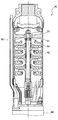
- FIG. 1 is a schematic diagram showing a schematic configuration of a pump 20 as an embodiment of the present invention.
- the pump 20 is a deep well multistage pump.
- the pump 20 may be any pump provided with a sliding bearing.
- the pump 20 includes a sliding bearing 30, a shaft 40, a parallel pin 50, a thrust bearing 60, and a motor 80.
- One end of the shaft 40 is rotatably supported by a sliding bearing 30 provided on the tip side (that is, opposite to the motor 80) from the thrust bearing 60, and the other end of the shaft 40 is supported by the motor 80. It is rotatably supported by a bearing (not shown) provided inside.
- a bearing sleeve 31 is disposed between the sliding bearing 30 and the shaft 40.
- the bearing sleeve 31 rotates with the shaft 40 when the shaft 40 rotates. That is, the bearing sleeve 31 and the shaft 40 rotate integrally while maintaining the same relative position (however, in the initial rotation of the shaft 40, the bearing sleeve 31 and the shaft 40 are relatively separated by a small distance. May rotate).
- the outer peripheral surface of the bearing sleeve 31 slides on the sliding surface of the sliding bearing 30 on the fixed side.
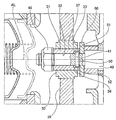
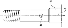
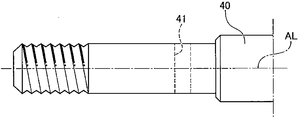
- FIG. 2 is an enlarged view of the periphery of the plain bearing 30 shown in FIG. 3A and 3B are diagrams showing the configuration of the shaft 40.
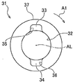
- FIG. 4A and 4B are diagrams showing the configuration of the bearing sleeve 31.
- the bearing sleeve 31 has a substantially cylindrical shape extending in the direction of the central axis (that is, the rotational central axis) AL of the shaft 40. Inside the bearing sleeve 31, a sleeve through hole 32 that penetrates the bearing sleeve 31 in the direction of the central axis AL is formed. As shown in FIG.
- the nut 45 is attached to the tip of the shaft 40 with the shaft 40 inserted into the sleeve through hole 32 on the tip side of the thrust bearing 60.
- the bearing sleeve 31 is attached to the shaft 40.
- a sliding bearing 30 which is a fixed side is arranged.
- the plain bearing 30 is supported by bearing support members 39 arranged above and below it.
- two notches 33 and 34 are partially formed in the circumferential direction (that is, spaced apart in the circumferential direction) at the end of the bearing sleeve 31 on the motor 80 side. .
- the notches 33 and 34 are formed at positions 180 degrees rotationally symmetric with respect to the central axis AL.
- the notches 33 and 34 extend from the sleeve through hole 32 toward the radially outer side.
- the notches 33 and 34 are formed in a substantially U shape, and are formed in a range that does not reach the outer peripheral surface 37 of the bearing sleeve 31 in the radial direction. In other words, the outer peripheral surface 37 of the bearing sleeve 31 is not cut out in any region.
- the shaft 40 is formed with a shaft through hole 41 that penetrates the shaft 40 in the direction intersecting the central axis AL of the shaft 40 in the vicinity of the thrust bearing 60.
- the shaft through hole 41 is formed to extend in a direction orthogonal to the central axis AL.
- the shaft through hole 41 is formed so as to pass on the central axis AL.
- a parallel pin 50 as an example of a rod-shaped member is inserted into the shaft through hole 41. Since the parallel pin 50 is a general-purpose standard part, in this way, the procurement and economy are excellent. However, any bar-like member can be used in place of the parallel pin 50. For example, a spring pin may be used instead of the parallel pin 50.
- the outer diameter of the parallel pin 50 is formed as large as possible within a range in which the parallel pin 50 can be inserted into the shaft through hole 41. That is, the clearance between the parallel pin 50 and the shaft through hole 41 is set as small as possible.
- the parallel pin 50 is inserted so that both ends thereof protrude to the outside of the shaft 40.
- the protruding portions at both ends of the parallel pin 50 are referred to as protruding portions 51 and 52, respectively.
- the protruding portions 51 and 52 are accommodated in notches 33 and 34 formed in the bearing sleeve 31, respectively.
- the notches 33 and 34 are arranged such that both ends of the parallel pins 50 are shafts even when one of the protruding portions 51 and 52 abuts against one radial end face of the corresponding notches 33 and 34. 40 is formed so as to protrude to the outside.
- the notches 33 and 34 are formed so that the clearance in the circumferential direction with the projecting portions 51 and 52 is minimized.
- the notches 33 and 34 are provided with the surfaces 35 and 36 extended in the direction where the protrusion parts 51 and 52 extend. For this reason, when the protrusion parts 51 and 52 and the surfaces 35 and 36 each contact
- the integral rotation of the shaft 40 and the bearing sleeve 31 can be realized with a simple configuration.
- machining the shaft through hole 41 in the shaft 40 is economical because it can be performed with a simple tool as compared with the case of performing keyway machining.
- the machining shape of the shaft 40 is simple, the machining time can be shortened.
- the above-described configuration can be widely applied to the small-diameter shaft 40 without any problem.
- the shaft through hole 41 is formed so as to extend in a direction orthogonal to the central axis AL. Accordingly, when the shaft 40 is processed, the processing tool can be easily positioned (orientated) with respect to the shaft 40, so that the shaft through hole 41 can be easily processed.
- the shaft through hole 41 is formed so as to extend in a direction orthogonal to the central axis AL, the projecting portions 51 and 52 are arranged at the same position in the direction of the central axis AL, and the bearing sleeve.
- the positions of the notches 33 and 34 formed in 31 can be the same position in the direction of the central axis AL.
- the shaft through hole 41 may be formed to extend in an arbitrary direction intersecting with the central axis AL.
- the shaft through hole 41 is a through hole passing on the central axis AL.
- the parallel pin 50 is not disposed with a deviation from the central axis AL. Therefore, the rotation balance of the shaft 40 can be easily maintained, and the rotation balance of the rotating body (the shaft 40, the bearing sleeve 31 and the parallel pin 50) can be further easily maintained.
- the shaft through hole 41 may be a through hole that does not pass through the central axis AL.
- the surfaces 35 and 36 of the bearing sleeve 31 come into contact with the protruding portions 51 and 52 in a line. Therefore, the parallel pin 50 is less likely to be deformed than in the case of contact at a point.
- the surfaces 35 and 36 may be formed in a curved surface shape that follows the outer peripheral surface of the parallel pin 50. In this case, the surfaces 35 and 36 come into contact with the protruding portions 51 and 52 at the surface, and the same effect is obtained. However, the surfaces 35 and 36 may contact the protruding portions 51 and 52 at points.
- the notches 33 and 34 of the bearing sleeve 31 are formed in a range that does not reach the outer peripheral surface 37 of the bearing sleeve 31 in the radial direction. That is, the outer peripheral surface 37 is not cut out in any region. For this reason, the outer peripheral surface 37 whole can be utilized as a sliding surface. Therefore, the bearing sleeve 31 can be downsized in the direction of the central axis AL, and consequently the pump 20 can be downsized.
- the notches 33 and 34 may be formed so as to reach the outer peripheral surface 37 of the bearing sleeve 31 in the radial direction.
- the above-described configuration of the present embodiment is not limited to the deep well multi-stage pump, and can be applied to any rotary device including a sliding bearing.
- the above-described embodiments may be applied to any type of pump, a blower, a compressor, or the like that includes a sliding bearing.
Landscapes
- Engineering & Computer Science (AREA)
- General Engineering & Computer Science (AREA)
- Mechanical Engineering (AREA)
- Sliding-Contact Bearings (AREA)
- Structures Of Non-Positive Displacement Pumps (AREA)
- Mounting Of Bearings Or Others (AREA)
Abstract
滑り軸受を備える回転機器において、簡単な構成で問題なく、シャフトと軸受スリーブとの間での相対的な回転を抑制する。 回転機器は、軸受スリーブと、軸受スリーブに形成されたスリーブ貫通穴に挿入されるシャフトであって、シャフトの中心軸線と交差する方向にシャフトを貫通するシャフト貫通穴が形成されたシャフトと、シャフト貫通穴に挿入される棒状部材であって、棒状部材の両端がシャフトの外部に突出する棒状部材と、を備える。軸受スリーブには、軸受スリーブ貫通穴から径方向外側に向けて、周方向において部分的に2つの切欠が形成される。棒状部材の両端の突出部分の各々は、2つの切欠内に収容される。
Description
本発明は、回転機器に関し、より詳細には、すべり軸受に関する。
小型の深井戸用多段ポンプでは、シャフトを支承するために、滑り軸受が使用されることがある。また、滑り軸受とシャフトとの間での摺動によってシャフトが摩耗することを防止するために、シャフトの外周面に軸受スリーブが取り付けられることがある。軸受スリーブは、シャフトが回転する際にシャフトとともに回転し、軸受スリーブの外周面は、シャフトの回転に伴って滑り軸受の摺動面上を摺動する。かかる深井戸用多段ポンプでは、従来、シャフトの周囲に、軸受スリーブの側方から軸受スリーブを押圧する方向にナットを締め付けることによって、シャフトと軸受スリーブとが相対的に回転することを防止していた。しかしながら、このような方法では、シャフトと軸受スリーブとを固定する力が弱いので、何らかの理由によって軸受スリーブの外周面と滑り軸受の摺動面との間の滑り抵抗が大きくなると、シャフトが回転した際に、軸受スリーブとシャフトとが相対的に回転するおそれがある。このような相対的な回転は、トラブルの要因となる。
そこで、軸受スリーブとシャフトとの間での相対的な回転をより確実に防止するために、廻り止め機構が設けられたポンプが開発されている。例えば、下記の特許文献1では、いくつかの廻り止め機構を開示している。その1つ目の例は、軸受スリーブおよびシャフトに設けられたキー溝構造である。2つ目の例は、径方向に延在するようにシャフトに形成された非貫通穴に挿入されたピンと、軸受スリーブと、を係合させる構成である。この場合、ピンのうちの、シャフトから突出した部分は、径方向に貫通するように(つまり、径方向外側縁部に到達するように)軸受スリーブに形成された切欠に収容される。
しかしながら、上記の1つ目の従来例では、キーの規格による標準サイズは限定的であるので、シャフトの小さな径に応じたキーを選択しようとすると、選択肢が非常に限定される。しかも、キー溝の加工は、比較的複雑である。また、上記の2つ目の従来例は、径が小さい(例えば、直径6mm)シャフトには適用しにくい。例えば、シャフトの径が小さい場合には、非貫通穴の奥行き(深さ)を短くする必要があるが、そのような短い奥行きの非貫通穴は加工精度の管理が行いにくい。また、加工精度に起因して、非貫通穴の奥行きが設計値よりも小さくなってしまうと、例えば、シャフトが回転した際に、ピンが変形して非貫通穴から抜け出る恐れがある。さらに、軸受スリーブに形成された切欠が径方向に貫通しているので、滑り軸受の摺動面上を摺動する、軸受スリーブの外周面が切欠の分だけ低減する。その結果、十分な摺動面積を確保するために、軸受スリーブを中心軸線の方向に大きくする必要が生じ、装置の大型化を招くことになる。これらの問題は、深井戸用多段ポンプに限らず、滑り軸受を備える回転機器全般に共通する。このようなことから、簡単な構成で問題なく、シャフトと軸受スリーブとを一体的に回転させる構成が求められる。また、このような構成は、比較的径が小さいシャフトなど、様々なシャフトに広く適用できることが望ましい。また、このような構成は、容易に加工できること、また、短時間で容易に製造できることが望ましい。また、このような構成は、安価であることが望ましい。さらに、回転バランスが良い回転機器が提供されることが望ましい。また、回転機器を小型化することが望ましい。
本発明は、上述の課題の少なくとも一部を解決するためになされたものであり、以下の形態として実現することが可能である。
本発明の第1の形態によれば、回転機器が提供される。この回転機器は、軸受スリーブと、軸受スリーブに形成されたスリーブ貫通穴に挿入されるシャフトであって、シャフトの中心軸線と交差する方向にシャフトを貫通するシャフト貫通穴が形成されたシャフトと、シャフト貫通穴に挿入される棒状部材であって、棒状部材の両端がシャフトの外部に突出する棒状部材と、を備える。軸受スリーブには、軸受スリーブ貫通穴から径方向外側に向けて、周方向において部分的に2つの切欠が形成される。棒状部材の両端の突出部分の各々は、2つの切欠内に収容される。
かかる回転機器によれば、シャフトが回転する際(回転初期を除く)に、棒状部材の両端の突出部分が、軸受スリーブの2つの切欠を形成する面に当接するので、シャフトと軸受スリーブとを一体的に回転させることができる。また、キー溝加工を行う場合と比べて、当該一体的な回転を簡単な構成によって実現できる。また、キー溝加工を行う場合と比べて、簡単な工具でシャフト貫通穴を加工できるので、経済的であり、また、加工形状が単純であるので、加工時間も短くて済む。しかも、シャフト貫通穴の加工には、非貫通穴の加工時のような穴の深さの加工精度管理も必要ない。さらに、この構成は、小径のシャフトなどにも問題なく広く適用可能である。
本発明の第2の形態によれば、第1の形態において、シャフト貫通穴は、中心軸線と直交する方向に延在するように形成される。かかる形態によれば、シャフトの加工時において、シャフトに対する加工工具の位置決め(向き決め)が容易になるので、シャフト貫通穴を加工しやすい。さらに、棒状部材の両端の突出部分が、中心軸線の方向において同一位置に配置されるので、突出部分を収容する、軸受スリーブの切欠の位置も、中心軸線の方向において同一位置に配置される。この点からも、回転体(シャフト、軸受スリーブおよび棒状部材)の回転バランスを保ちやすい。
本発明の第3の形態によれば、第1または第2の形態において、シャフト貫通穴は、シャフトの中心軸線上を通る貫通穴である。かかる形態によれば、シャフトの回転バランスを保ちやすく、回転体(シャフト、軸受スリーブおよび棒状部材)の回転バランスをさらに保ちやすい。このように回転バランスを保つことによって、シャフトが高速回転する場合であっても、アンバランスに伴う振動等の発生を抑制できる。
本発明の第4の形態によれば、第1ないし第3のいずれかの形態において、軸受スリーブの切欠を形成する面は、棒状部材の突出部分が延在する方向に延在する面であって、シャフトが回転する際に突出部分と線または面で当接するように形成された面を備える。かかる形態によれば、軸受スリーブの切欠を形成する面と突出部分とが点で当接する場合と比べて、棒状部材が変形しにくい。
本発明の第5の形態によれば、第1ないし第4のいずれかの形態において、軸受スリーブの切欠は、径方向において、軸受スリーブの外周面まで到達しない範囲で形成される。かかる形態によれば、軸受スリーブの摺動面すなわち外周面が切り欠かれないので、軸受スリーブの外周面全体を摺動面として利用することができる。したがって、切欠が軸受スリーブの外周面まで到達する場合と比べて、軸受スリーブを小型化でき、ひいては、回転機器を小型化できる。
本発明の第6の形態によれば、第1ないし第5のいずれかの形態において、棒状部材は、平行ピンである。平行ピンは汎用の標準部品であるので、かかる形態によれば、調達性および経済性に優れる。
A.実施例:
図1は、本発明の一実施例としてのポンプ20の概略構成を示す概略図である。本実施例では、ポンプ20は、深井戸用多段ポンプである。ただし、ポンプ20は、滑り軸受を備える任意のポンプであってもよい。図1に示すように、ポンプ20は、滑り軸受30と、シャフト40と、平行ピン50と、スラスト軸受60と、モータ80と、を備えている。シャフト40の一方の端部は、スラスト軸受60よりも先端側(すなわち、モータ80と反対側)に設けられた滑り軸受30によって回転可能に支承され、シャフト40の他方の端部は、モータ80内に設けられた軸受(図示省略)によって回転可能に支承されている。シャフト40の周囲には、滑り軸受30とシャフト40との間に軸受スリーブ31が配置されている。この軸受スリーブ31は、シャフト40が回転する際にシャフト40とともに回転する。つまり、軸受スリーブ31とシャフト40とは、同一の相対位置を維持した状態で一体的に回転する(ただし、シャフト40の回転初期においては、軸受スリーブ31とシャフト40とが僅かな距離だけ相対的に回転することがある)。軸受スリーブ31の外周面は、固定側である滑り軸受30の摺動面上を摺動する。このように軸受スリーブ31を設けることによって、シャフト40が滑り軸受30の摺動面に対して摺動する事によって摩耗することがない。以下、軸受スリーブ31とシャフト40とを一体的に回転させるための構成について説明する。
図1は、本発明の一実施例としてのポンプ20の概略構成を示す概略図である。本実施例では、ポンプ20は、深井戸用多段ポンプである。ただし、ポンプ20は、滑り軸受を備える任意のポンプであってもよい。図1に示すように、ポンプ20は、滑り軸受30と、シャフト40と、平行ピン50と、スラスト軸受60と、モータ80と、を備えている。シャフト40の一方の端部は、スラスト軸受60よりも先端側(すなわち、モータ80と反対側)に設けられた滑り軸受30によって回転可能に支承され、シャフト40の他方の端部は、モータ80内に設けられた軸受(図示省略)によって回転可能に支承されている。シャフト40の周囲には、滑り軸受30とシャフト40との間に軸受スリーブ31が配置されている。この軸受スリーブ31は、シャフト40が回転する際にシャフト40とともに回転する。つまり、軸受スリーブ31とシャフト40とは、同一の相対位置を維持した状態で一体的に回転する(ただし、シャフト40の回転初期においては、軸受スリーブ31とシャフト40とが僅かな距離だけ相対的に回転することがある)。軸受スリーブ31の外周面は、固定側である滑り軸受30の摺動面上を摺動する。このように軸受スリーブ31を設けることによって、シャフト40が滑り軸受30の摺動面に対して摺動する事によって摩耗することがない。以下、軸受スリーブ31とシャフト40とを一体的に回転させるための構成について説明する。
図2は、図1に示す滑り軸受30の周辺の拡大図である。図3Aおよび図3Bは、シャフト40の構成を示す図である。図4Aおよび図4Bは、軸受スリーブ31の構成を示す図である。図2、図4Aおよび図4Bに示すように、軸受スリーブ31は、シャフト40の中心軸線(すなわち、回転中心軸線)ALの方向に延在する略円筒形状を有している。軸受スリーブ31の内部には、中心軸線ALの方向に軸受スリーブ31を貫通するスリーブ貫通穴32が形成されている。図2に示すように、スラスト軸受60よりも先端側において、シャフト40がスリーブ貫通穴32に挿入された状態でナット45がシャフト40の先端に取り付けられている。これによって、軸受スリーブ31がシャフト40に取り付けられている。軸受スリーブ31の周囲には、固定側である滑り軸受30が配置されている。滑り軸受30は、その上下に配置された軸受支持部材39によって支持されている。
図4Aおよび図4Bに示すように、軸受スリーブ31のモータ80側の端部には、2つの切欠33,34が周方向に部分的に(つまり、周方向に離間して)形成されている。切欠33,34は、中心軸線ALを基準として180度回転対称の位置に形成されている。切欠33、34は、スリーブ貫通穴32から径方向外側に向けて延在している。本実施例では、切欠33,34は、略U字形状に形成されており、径方向において、軸受スリーブ31の外周面37まで到達しない範囲で形成されている。換言すれば、軸受スリーブ31の外周面37は、いずれの領域においても切り欠かかれていない。
図2に示すように、シャフト40には、スラスト軸受60の近傍において、シャフト40の中心軸線ALと交差する方向にシャフト40を貫通するシャフト貫通穴41が形成されている。図3Aおよび図3Bに示すように、本実施例では、シャフト貫通穴41は、中心軸線ALと直交する方向に延在するように形成されている。また、本実施例では、シャフト貫通穴41は、中心軸線AL上を通るように形成されている。
図2に示すように、シャフト貫通穴41には、棒状部材の一例としての平行ピン50が挿入されている。平行ピン50は、汎用の標準部品であるので、このようにすれば、調達性および経済性に優れる。ただし、平行ピン50に代えて、任意の棒状部材を使用することが可能である。例えば、平行ピン50に代えてスプリングピンが使用されてもよい。平行ピン50の外径は、平行ピン50をシャフト貫通穴41に挿入できる範囲内で極力大きく形成されている。つまり、平行ピン50とシャフト貫通穴41とのクリアランスは、極力小さく設定される。平行ピン50は、その両端がシャフト40の外部に突出するように挿入されている。この平行ピン50の両端の突出した部分を、それぞれ突出部分51,52と呼ぶ。この突出部分51,52は、それぞれ、軸受スリーブ31に形成された切欠33,34に収容されている。本実施例では、切欠33,34は、突出部分51,52の一方が、対応する切欠33,34の一方の径方向の端面に当接した場合であっても、平行ピン50の両端がシャフト40の外部に突出するように形成されている。また、切欠33,34は、突出部分51,52との周方向のクリアランスが極力小さくなるように形成されている。また、図4Bに示すように、切欠33,34は、突出部分51,52が延在する方向に延在する面35,36を備えている。このため、突出部分51,52と面35,36とがそれぞれ当接する際には、これらは、線で当接することになる。
かかる構成のポンプ20は、モータ80を駆動することによってシャフト40が矢印A1(図4B参照)の方向に回転すると、シャフト貫通穴41に挿入された平行ピン50もシャフト40と一体的に回転する。このとき、平行ピン50と面35,36との間にクリアランスが存在する場合には、僅かな時間だけ、平行ピン50と軸受スリーブ31とが相対的に回転し、平行ピン50が、面35,36と当接する。その後、シャフト40の回転力は、突出部分51,52と面35,36との当接部分を介して軸受スリーブ31に伝達されるので、シャフト40と軸受スリーブ31との相対位置が固定された状態で、シャフト40と軸受スリーブ31とは一体的に回転する。平行ピン50と面35,36との間にクリアランスが存在しない場合には、シャフト40の回転初期からシャフト40と軸受スリーブ31とは一体的に回転する。
かかるポンプ20によれば、軸受スリーブ31およびシャフト40にキー溝加工を行う場合と比べて、シャフト40と軸受スリーブ31との一体的な回転を簡単な構成によって実現できる。また、シャフト40にシャフト貫通穴41を加工することは、キー溝加工を行う場合と比べて、簡単な工具で実施できるので、経済的である。また、シャフト40の加工形状が単純であるので、加工時間も短くて済む。しかも、上述した構成は、小径のシャフト40にも問題なく広く適用可能である。
また、ポンプ20によれば、シャフト貫通穴41は、中心軸線ALと直交する方向に延在するように形成される。したがって、シャフト40の加工時において、シャフト40に対する加工工具の位置決め(向き決め)が容易になるので、シャフト貫通穴41を加工しやすい。しかも、シャフト貫通穴41が中心軸線ALと直交する方向に延在するように形成されることによって、突出部分51,52が中心軸線ALの方向において同一位置に配置されることになり、軸受スリーブ31に形成される切欠33,34の位置についても中心軸線ALの方向において同一位置とすることができる。このため、回転体全体(すなわち、シャフト40、軸受スリーブ31および平行ピン50)についても回転バランスを保ちやすい。ただし、シャフト貫通穴41は、中心軸線ALと交差する任意の方向に延在するように形成されてもよい。
また、ポンプ20によれば、シャフト貫通穴41は、中心軸線AL上を通る貫通穴である。このため、平行ピン50が中心軸線ALに対して偏って配置されることがない。したがって、シャフト40の回転バランスについても保ちやすく、回転体(シャフト40、軸受スリーブ31および平行ピン50)の回転バランスをさらに保ちやすい。ただし、シャフト貫通穴41は、中心軸線AL上を通らない貫通穴であってもよい。
また、ポンプ20によれば、シャフト40が回転する際に、軸受スリーブ31の面35,36が突出部分51,52と線で当接する。したがって、点で当接する場合と比べて、平行ピン50が変形しにくい。面35,36は、平行ピン50の外周面に追従する曲面形状に形成されてもよい。この場合は、面35,36は突出部分51,52と面で当接することになり、同様の効果を奏する。ただし、面35,36は突出部分51,52とは、点で当接してもよい。
また、ポンプ20によれば、軸受スリーブ31の切欠33,34は、径方向において、軸受スリーブ31の外周面37まで到達しない範囲で形成される。つまり、外周面37は、いずれの領域においても切り欠かれない。このため、外周面37全体を摺動面として利用することができる。したがって、軸受スリーブ31を中心軸線ALの方向に小型化でき、ひいては、ポンプ20を小型化できる。ただし、切欠33,34は、径方向において、軸受スリーブ31の外周面37まで到達するように形成されてもよい。
上述した本実施例の構成は、深井戸用多段ポンプに限らず、滑り軸受を備える任意の回転機器に適用可能である。例えば、上述の実施例は、滑り軸受を備える任意の形式のポンプ、送風機、圧縮機などに適用されてもよい。
以上、いくつかの実施例に基づいて本発明の実施の形態について説明してきたが、上記した発明の実施の形態は、本発明の理解を容易にするためのものであり、本発明を限定するものではない。本発明は、その趣旨を逸脱することなく、変更、改良され得るとともに、本発明にはその等価物が含まれることはもちろんである。また、上述した課題の少なくとも一部を解決できる範囲、または、効果の少なくとも一部を奏する範囲において、特許請求の範囲および明細書に記載された各構成要素の任意の組み合わせ、または、省略が可能である。
本願は、2015年2月16日付の日本国特許出願2015-27516号に基づく優先権を主張する。2015年2月16日付の日本国特許出願2015-27516号の明細書、特許請求の範囲、図面及び要約書を含む全ての開示内容は、参照により全体として本願に組み込まれる。
実開昭60-114296号公報(特許文献1)の明細書、特許請求の範囲、図面及び要約書を含む全ての開示は、参照により全体として本願に組み込まれる。
実開昭60-114296号公報(特許文献1)の明細書、特許請求の範囲、図面及び要約書を含む全ての開示は、参照により全体として本願に組み込まれる。
20…ポンプ
30…滑り軸受
31…軸受スリーブ
32…スリーブ貫通穴
33,34…切欠
35,36…面
37…外周面
39…軸受支持部材
40…シャフト
41…シャフト貫通穴
45…ナット
50…平行ピン
51,52…突出部分
60…スラスト軸受
80…モータ
AL…中心軸線
30…滑り軸受
31…軸受スリーブ
32…スリーブ貫通穴
33,34…切欠
35,36…面
37…外周面
39…軸受支持部材
40…シャフト
41…シャフト貫通穴
45…ナット
50…平行ピン
51,52…突出部分
60…スラスト軸受
80…モータ
AL…中心軸線
Claims (6)
- 回転機器であって、
軸受スリーブと、
前記軸受スリーブに形成されたスリーブ貫通穴に挿入されるシャフトであって、該シャフトの中心軸線と交差する方向に該シャフトを貫通するシャフト貫通穴が形成されたシャフトと、
前記シャフト貫通穴に挿入される棒状部材であって、該棒状部材の両端が前記シャフトの外部に突出する棒状部材と
を備え、
前記軸受スリーブには、前記軸受スリーブ貫通穴から径方向外側に向けて、周方向において部分的に2つの切欠が形成され、
前記棒状部材の前記両端の突出部分の各々は、前記2つの切欠内に収容される
回転機器。 - 請求項1に記載の回転機器であって、
前記シャフト貫通穴は、前記中心軸線と直交する方向に延在するように形成された
回転機器。 - 請求項1または請求項2に記載の回転機器であって、
前記シャフト貫通穴は、前記シャフトの前記中心軸線上を通る貫通穴である
回転機器。 - 請求項1ないし請求項3のいずれか一項に記載の回転機器であって、
前記軸受スリーブの前記切欠を形成する面は、前記棒状部材の前記突出部分が延在する方向に延在する面であって、前記シャフトが回転する際に前記突出部分と線または面で当接するように形成された面を備える
回転機器。 - 請求項1ないし請求項4のいずれか一項に記載の回転機器であって、
前記軸受スリーブの前記切欠は、径方向において、前記軸受スリーブの外周面まで到達しない範囲で形成された
回転機器。 - 請求項1ないし請求項5のいずれか一項に記載の回転機器であって、
前記棒状部材は、平行ピンである
回転機器。
Applications Claiming Priority (2)
| Application Number | Priority Date | Filing Date | Title |
|---|---|---|---|
| JP2015027516A JP2016151180A (ja) | 2015-02-16 | 2015-02-16 | 回転機器 |
| JP2015-027516 | 2015-02-16 |
Publications (1)
| Publication Number | Publication Date |
|---|---|
| WO2016133031A1 true WO2016133031A1 (ja) | 2016-08-25 |
Family
ID=56688859
Family Applications (1)
| Application Number | Title | Priority Date | Filing Date |
|---|---|---|---|
| PCT/JP2016/054220 Ceased WO2016133031A1 (ja) | 2015-02-16 | 2016-02-15 | 回転機器 |
Country Status (3)
| Country | Link |
|---|---|
| JP (1) | JP2016151180A (ja) |
| TW (1) | TW201631263A (ja) |
| WO (1) | WO2016133031A1 (ja) |
Families Citing this family (1)
| Publication number | Priority date | Publication date | Assignee | Title |
|---|---|---|---|---|
| CN115076249B (zh) * | 2022-07-18 | 2023-06-20 | 安徽百通达科技医疗用品有限公司 | 一种耐用型联轴器 |
Citations (3)
| Publication number | Priority date | Publication date | Assignee | Title |
|---|---|---|---|---|
| JPS60114296U (ja) * | 1984-01-10 | 1985-08-02 | 株式会社川本製作所 | ポンプ用主軸支持構造 |
| JPH03321U (ja) * | 1989-05-26 | 1991-01-07 | ||
| JP2008286407A (ja) * | 2008-08-28 | 2008-11-27 | Tok Bearing Co Ltd | トルクリミッター |
-
2015
- 2015-02-16 JP JP2015027516A patent/JP2016151180A/ja active Pending
-
2016
- 2016-02-03 TW TW105103458A patent/TW201631263A/zh unknown
- 2016-02-15 WO PCT/JP2016/054220 patent/WO2016133031A1/ja not_active Ceased
Patent Citations (3)
| Publication number | Priority date | Publication date | Assignee | Title |
|---|---|---|---|---|
| JPS60114296U (ja) * | 1984-01-10 | 1985-08-02 | 株式会社川本製作所 | ポンプ用主軸支持構造 |
| JPH03321U (ja) * | 1989-05-26 | 1991-01-07 | ||
| JP2008286407A (ja) * | 2008-08-28 | 2008-11-27 | Tok Bearing Co Ltd | トルクリミッター |
Also Published As
| Publication number | Publication date |
|---|---|
| TW201631263A (zh) | 2016-09-01 |
| JP2016151180A (ja) | 2016-08-22 |
Similar Documents
| Publication | Publication Date | Title |
|---|---|---|
| JP5269461B2 (ja) | 流体力学的流体膜ジャーナル軸受システム | |
| JP6121967B2 (ja) | バランサ錘を備える回転子、およびモータ | |
| JP5772924B2 (ja) | スクリュー圧縮機 | |
| EP2679826A1 (en) | Impeller, rotor comprising same, and impeller manufacturing method | |
| CN105584517A (zh) | 转向系统 | |
| EP1314904B1 (en) | A method for mounting a sleeve on a shaft and a sleeve device for such mounting | |
| CN105584518A (zh) | 齿条轴衬和转向系统 | |
| US9964153B2 (en) | Support device for bearing | |
| KR20170015193A (ko) | 편심 요동형 기어 장치 및 그 제조 방법 | |
| CN105605080B (zh) | 拼合滚珠套筒 | |
| JP5777529B2 (ja) | インペラ及びこれを備えたロータ並びにインペラの製造方法 | |
| JP6440466B2 (ja) | 偏心揺動型歯車装置 | |
| CN110809677B (zh) | 用于制造可倾瓦轴承的构件的方法和可倾瓦轴承 | |
| JP2010236539A (ja) | ポンプ用固定軸 | |
| WO2016133031A1 (ja) | 回転機器 | |
| JPH07184339A (ja) | モータの取付け構造 | |
| CN107002518A (zh) | 用于凸轮轴相位器中的弹簧导引件的支承销 | |
| US20070128044A1 (en) | Fluid machine | |
| CN105041983B (zh) | 齿轮传动装置 | |
| JP2017089427A5 (ja) | ||
| JP2008208952A (ja) | 軸継手の軸締結構造 | |
| KR20160105879A (ko) | 기어 전동 장치 | |
| CN102694443B (zh) | 旋转电机及旋转电机的转子 | |
| JP6447724B2 (ja) | 回転機械 | |
| JP2015200384A (ja) | 回転軸支持装置及び電動モータ |
Legal Events
| Date | Code | Title | Description |
|---|---|---|---|
| 121 | Ep: the epo has been informed by wipo that ep was designated in this application |
Ref document number: 16752417 Country of ref document: EP Kind code of ref document: A1 |
|
| NENP | Non-entry into the national phase |
Ref country code: DE |
|
| 122 | Ep: pct application non-entry in european phase |
Ref document number: 16752417 Country of ref document: EP Kind code of ref document: A1 |