WO2016132866A1 - Medium transfer device - Google Patents
Medium transfer device Download PDFInfo
- Publication number
- WO2016132866A1 WO2016132866A1 PCT/JP2016/052730 JP2016052730W WO2016132866A1 WO 2016132866 A1 WO2016132866 A1 WO 2016132866A1 JP 2016052730 W JP2016052730 W JP 2016052730W WO 2016132866 A1 WO2016132866 A1 WO 2016132866A1
- Authority
- WO
- WIPO (PCT)
- Prior art keywords
- unit
- bundle
- medium
- storage
- banknote
- Prior art date
Links
Images


Classifications
-
- G—PHYSICS
- G07—CHECKING-DEVICES
- G07D—HANDLING OF COINS OR VALUABLE PAPERS, e.g. TESTING, SORTING BY DENOMINATIONS, COUNTING, DISPENSING, CHANGING OR DEPOSITING
- G07D11/00—Devices accepting coins; Devices accepting, dispensing, sorting or counting valuable papers
- G07D11/10—Mechanical details
- G07D11/16—Handling of valuable papers
-
- G—PHYSICS
- G07—CHECKING-DEVICES
- G07D—HANDLING OF COINS OR VALUABLE PAPERS, e.g. TESTING, SORTING BY DENOMINATIONS, COUNTING, DISPENSING, CHANGING OR DEPOSITING
- G07D1/00—Coin dispensers
-
- G—PHYSICS
- G07—CHECKING-DEVICES
- G07D—HANDLING OF COINS OR VALUABLE PAPERS, e.g. TESTING, SORTING BY DENOMINATIONS, COUNTING, DISPENSING, CHANGING OR DEPOSITING
- G07D11/00—Devices accepting coins; Devices accepting, dispensing, sorting or counting valuable papers
- G07D11/40—Device architecture, e.g. modular construction
-
- G—PHYSICS
- G07—CHECKING-DEVICES
- G07D—HANDLING OF COINS OR VALUABLE PAPERS, e.g. TESTING, SORTING BY DENOMINATIONS, COUNTING, DISPENSING, CHANGING OR DEPOSITING
- G07D9/00—Counting coins; Handling of coins not provided for in the other groups of this subclass
-
- B—PERFORMING OPERATIONS; TRANSPORTING
- B65—CONVEYING; PACKING; STORING; HANDLING THIN OR FILAMENTARY MATERIAL
- B65H—HANDLING THIN OR FILAMENTARY MATERIAL, e.g. SHEETS, WEBS, CABLES
- B65H2701/00—Handled material; Storage means
- B65H2701/10—Handled articles or webs
- B65H2701/19—Specific article or web
- B65H2701/1912—Banknotes, bills and cheques or the like
-
- B—PERFORMING OPERATIONS; TRANSPORTING
- B65—CONVEYING; PACKING; STORING; HANDLING THIN OR FILAMENTARY MATERIAL
- B65H—HANDLING THIN OR FILAMENTARY MATERIAL, e.g. SHEETS, WEBS, CABLES
- B65H43/00—Use of control, checking, or safety devices, e.g. automatic devices comprising an element for sensing a variable
- B65H43/04—Use of control, checking, or safety devices, e.g. automatic devices comprising an element for sensing a variable detecting, or responding to, presence of faulty articles
-
- B—PERFORMING OPERATIONS; TRANSPORTING
- B65—CONVEYING; PACKING; STORING; HANDLING THIN OR FILAMENTARY MATERIAL
- B65H—HANDLING THIN OR FILAMENTARY MATERIAL, e.g. SHEETS, WEBS, CABLES
- B65H5/00—Feeding articles separated from piles; Feeding articles to machines
- B65H5/02—Feeding articles separated from piles; Feeding articles to machines by belts or chains, e.g. between belts or chains
- B65H5/021—Feeding articles separated from piles; Feeding articles to machines by belts or chains, e.g. between belts or chains by belts
- B65H5/023—Feeding articles separated from piles; Feeding articles to machines by belts or chains, e.g. between belts or chains by belts between a pair of belts forming a transport nip
-
- G—PHYSICS
- G07—CHECKING-DEVICES
- G07D—HANDLING OF COINS OR VALUABLE PAPERS, e.g. TESTING, SORTING BY DENOMINATIONS, COUNTING, DISPENSING, CHANGING OR DEPOSITING
- G07D9/00—Counting coins; Handling of coins not provided for in the other groups of this subclass
- G07D9/002—Coin holding devices
Definitions
- the present disclosure relates to a medium delivery apparatus, and is suitable for application to, for example, a banknote dispensing machine that dispenses banknotes as a medium.
- banknote dispensing machines used in financial institutions and the like are widely used to withdraw cash such as banknotes and coins in response to requests from users (for example, customers of financial institutions).
- a banknote dispensing machine for example, a banknote storage for storing banknotes, a transport section for transporting banknotes, a discrimination section for identifying banknotes, a stacking section for stacking banknotes that can be withdrawn, and a banknote should be withdrawn.
- a reject storage for storing rejected banknotes
- a bundle transport unit for transporting a bundle of stacked banknotes
- a withdrawal port for delivering banknotes to a user. See, for example, Japanese Patent No. 5156097, particularly FIG.
- the banknote storage is configured to be detachable from the side of the housing.
- This banknote dispensing machine removes the banknote storage from the case when replenishing banknotes, and reloads the banknote storage into the case after replenishment of banknotes.
- the banknote dispensing machine has a different surface for removing the banknote storage from the housing depending on the installation location.
- a banknote dispenser may be installed in a building so that a rear surface opposite to the front surface provided with a dispensing port is opposed to and close to the wall surface of the building. In this case, it is desirable for the banknote dispenser to remove the banknote storage from the front.
- the banknote dispensing machine has, for example, a hole formed in the wall of the building, and only the periphery of the front outlet is exposed to the customer side space, and the rear surface is exposed to the clerk side space.
- a case may be installed. In this case, it is desirable for the banknote dispenser to remove the banknote storage from the rear surface in the space on the clerk side.
- the banknote dispensing machine has a configuration in which the banknote storage is removed from the front surface (hereinafter referred to as a front machine) or a banknote storage is removed from the rear surface (hereinafter referred to as a rear machine) depending on the installation location. It was necessary to prepare such two configurations.
- This disclosure has been made in consideration of the above points, and proposes a medium delivery device that can easily cope with restrictions on installation locations.
- a storage unit that stores a sheet-like medium and accumulates media to be delivered to a user to generate a medium bundle, and a medium bundle generated by the storage unit along the bundle conveyance path.
- a bundle delivery unit that conveys a bundle of media along the bundle conveyance path, and a bundle conveyance unit that conveys the bundle of media along the bundle conveyance path to one end side of the conveyance direction.
- the storage unit has a delivery port for delivering a medium bundle to a user, and the storage unit is normal by the discrimination unit for discriminating the medium storage unit for storing the medium, the medium fed out from the storage unit, and the discrimination unit.
- a reject storage unit that takes in a medium bundle from the feeding path, and a switching unit that is arranged between the stacking unit and the reject storage unit and switches the transport destination of the medium that has passed through the discrimination unit to the stacking unit or the reject storage unit, and Either one of the storage unit or the bundle transport unit is disposed at a connection location of the storage unit and the bundle transport unit, forms a part of the bundle transport path, and communicates the bundle transport path with the inside of the reject storage.
- the conveyance guide which changes a state and the state which connected the said bundle conveyance path and the inside of the stacking part is provided.
- the first aspect further includes a safe provided in a housing, and the medium storage is disposed in the safe and can be pulled out and stored in the housing.
- the bundle transport unit, the transport guide, the stacking unit, the reject storage, and the switching unit are disposed outside the safe and are provided so as to be able to be pulled out and stored in the housing.
- Medium delivery device is disposed outside the safe and are provided so as to be able to be pulled out and stored in the housing.
- the stacking unit is configured to provide a stacking hole that delivers the medium bundle to and from the bundle transport path at a position facing the bundle transport unit.
- the reject storage has a take-in hole for taking in the medium bundle from the bundle carrying path at a position facing the bundle carrying unit, and the carry guide takes in the open opening for opening the take-in hole. It is a medium delivery device that is moved to a position or an accumulation opening position that opens the accumulation hole.
- a fourth aspect of the present disclosure is the medium delivery apparatus according to the third aspect, wherein the conveyance guide closes the accumulation hole at the intake opening position and closes the intake hole at the accumulation opening position. It is.
- the stacking unit discharges the normal medium transported from the switching unit to an internal stacking space, and the transport guide is in the take-in open position.
- the medium delivery device prevents the normal medium discharged to the accumulation space from entering the bundle conveyance path.
- the conveyance guide is moved along the bundle conveyance path within a movement range connecting the take-in release position and the stacking release position, and the bundle conveyance unit Forming the bundle conveyance path by a part of the upper belt arranged above the conveyance guide and the conveyance guide in the movement range of the conveyance guide, and outside the movement range of the conveyance guide, In the medium delivery device, the remaining part of the upper belt and the lower belt disposed below the upper belt form the bundle conveyance path.
- the accumulation hole and the intake hole are provided at positions symmetrical to each other with respect to the transport direction with respect to the housing of the storage unit. It is a medium delivery device.
- the bundle conveyance unit has a large hole portion having a size including the collection hole and the intake hole on a facing surface facing the storage unit.
- a medium delivery device is provided.
- the stacking unit further includes a stage on which the normal medium is placed and moved in a direction crossing the transport direction, and the stage includes: The medium delivery device, which moves into the bundle conveyance unit to form a part of the bundle conveyance path when the conveyance guide is in the stacking release position.
- the stacking unit has a tilted posture in which the stage is tilted with respect to a horizontal direction when the normal medium is stacked on the stage.
- the medium delivery device is configured so that the stage is in a substantially horizontal position.
- An eleventh aspect of the present disclosure is the medium delivery apparatus according to the first or second aspect, wherein the discrimination unit is disposed adjacent to the medium storage case closest to the bundle conveyance unit. It is.
- the storage unit includes a transport unit that transports the medium fed out from the medium storage, and the medium storage is The medium delivery device in which the feeding unit that feeds the medium and delivers it to the transport unit is disposed in a location far from the bundle transport unit in the medium storage.
- the bundle conveyance unit pushes out the medium bundle along the bundle conveyance path, and at least from the bundle conveyance path in the vicinity of the delivery port. It is a medium delivery apparatus further provided with the extrusion part which retracts.
- the medium bundle is delivered between the storage unit and the bundle transport unit.
- the medium bundle can be delivered to the user from the delivery port.
- the present disclosure can switch the orientation of the detachable surface of the storage unit with respect to the delivery port without changing at least the configuration of the storage unit.
- FIG. 20A It is a basic diagram which shows the structure of the banknote dispensing machine by other embodiment. It is a basic diagram which shows the structure of the banknote dispensing machine by other embodiment. It is an approximate line figure showing the state where the bill dispensing machine by the modification of a 1st embodiment was assembled as a back machine. It is a figure which shows the structure of the rear surface machine of FIG. 19 installed in the housing
- the cash dispenser 1 is configured around a box-shaped housing 2, and is installed in, for example, a financial institution or the like (for example, a customer of a financial institution).
- the bank is now engaged in transactions related to cash such as withdrawal processing.
- the housing 2 is provided with a customer-facing unit 3 at a location where it is easy to take out bills or operate with a touch panel while the customer is facing the front side.
- the customer reception unit 3 exchanges, for example, cash or a card directly with the customer, and also notifies the transaction information and accepts operation instructions.
- an operation display unit 6, a numeric keypad 7, and a receipt issuing port 8 are provided.
- Card entry / exit 4 is a portion where various cards such as cash cards are inserted or ejected.
- a card processing unit (not shown) for reading account numbers and the like magnetically recorded on various cards is provided on the back side of the card slot 4.
- the housing withdrawal port 5 is opened or closed by driving a shutter, and in the opened state, banknotes withdrawn to the customer are discharged.
- the operation display unit 6 is a touch panel in which an LCD (Liquid Crystal Display) for displaying an operation screen at the time of a transaction and a touch sensor for inputting a transaction type, a password, a transaction amount, and the like are integrated.
- the numeric keypad 7 is a physical key that accepts input of numbers such as “0” to “9”, and is used when an input operation such as a password or transaction amount is performed.
- the receipt issuing port 8 is a part that issues a receipt on which transaction details are printed at the end of transaction processing. Incidentally, a receipt processing unit (not shown) for printing transaction contents and the like on the receipt is provided on the back side of the receipt issuing port 8.
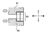
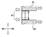
- the side facing the customer of the cash dispenser 1 is the front side, the opposite is the rear side, the left and right sides are the left side and the right side as viewed from the customer facing the front side, and the upper side and the lower side. Is defined and explained.
- a main control unit 9 that performs overall control of the cash dispenser 1 as a whole, a banknote dispenser 10 that performs various processes related to banknotes, and the like.
- the main control unit 9 is mainly configured by a CPU (Central Processing Unit) (not shown), and by reading and executing a predetermined program from a ROM (Read Only Memory), a flash memory or the like (not shown), a withdrawal process, etc. Various processes are performed.
- the main control unit 9 has a storage unit including a RAM (Random Access Memory), a hard disk drive, a flash memory, and the like, and stores various information in the storage unit.
- RAM Random Access Memory
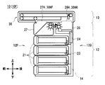
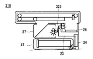
- the banknote dispensing machine 10 is roughly composed of a lower storage unit 12 and an upper bundle transport unit 13, and further includes a control unit 14 for controlling the whole. It is.
- control unit 14 is mainly configured by a CPU (not shown). By reading and executing a predetermined program from a ROM, flash memory, or the like (not shown), a withdrawal process, etc. Perform the process.
- the control unit 14 includes a storage unit including a RAM, a hard disk drive, a flash memory, and the like, and stores various information in the storage unit.
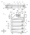
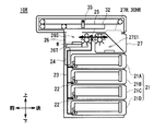
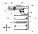
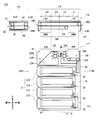
- the storage unit 12 includes a plurality of portions that perform various processes related to banknotes in a rectangular parallelepiped storage housing 20.
- the storage case 20 four banknote storages 21 (21A, 21B, 21C, and 21D), a transport unit 23, a discrimination unit 24, a switching unit 25, a stacking unit 26, and a reject storage unit 27 are provided. Yes.
- the banknote storage 21 (21A, 21B, 21C, and 21D) is attached so as to be stacked on each other from the center in the vertical direction on the front side of the storage housing 20 to the lower side.
- Each banknote storage 21 is formed in a flat rectangular parallelepiped shape that is short in the up-down direction and long in the front-rear direction, and has a state in which the paper surface is lined up in the front-rear direction along the front-rear direction, so-called lateral accumulation state.
- the banknotes are stored.
- a feeding unit 22 that separates and feeds out the stored banknotes one by one is provided at the rear lower part of the banknote storage 21, that is, at a position far from the bundle transport unit 13.
- Each banknote storage 21 can be removed from the storage housing 20 by being pulled forward with respect to the storage housing 20, and can be pushed rearward in alignment with the storage housing 20. Thus, it can be attached to the storage housing 20. That is, each banknote storage 21 is configured to be detachable from the front surface of the storage housing 20. Each banknote storage 21 has a predetermined denomination of banknotes stored therein.
- the transport unit 23 constitutes a transport path that is a path for transporting banknotes by a roller or a belt (not shown), or a motor that drives these. As shown by the solid line in the figure, this transport path is connected to the feeding portion 22 of each banknote storage 21, travels along the rear side of each banknote storage 21, and is located at the uppermost position. It arrange
- the discrimination unit 24 is provided on the rear side portion of the banknote storage 21 ⁇ / b> A in the transport unit 23 along the transport path of the transport unit 23, that is, along the direction approaching the bundle transport unit 13. That is, the discrimination unit 24 is installed at a location where the distance from the bundle transport unit 13 is substantially equal to the bill storage case 21A.
- a plurality of types of sensors such as a thickness sensor and an image sensor are incorporated in the discrimination unit 24, and based on the information obtained from each sensor, the denomination and running state of the bills to be conveyed are discriminated,
- the discrimination result is supplied to the control unit 14.
- the control part 14 determines the conveyance destination of each banknote based on the obtained discrimination result. Specifically, the control unit 14 sets the transport destination of normal banknotes to be withdrawn to the stacking unit 26, and the transport destination of abnormal banknotes that should not be withdrawn (hereinafter referred to as reject banknotes) to the reject storage box 27. Each is determined.
- the switching unit 25 is disposed substantially at the center in the front-rear direction on the upper side of the banknote storage 21 ⁇ / b> A, and based on the control of the control unit 14, is a blade (shown by a triangle in the drawing) that contacts the banknote and changes the traveling direction. By changing the inclination angle, the direction of travel of the banknote is switched.
- the switching unit 25 is connected to the lower discrimination unit 24, the rear stacking unit 26, and the front reject storage 27 by the transport unit 23.
- the switching unit 25 switches the traveling direction of each bill transported from below according to the transport destination determined by the control unit 14. Specifically, the switching unit 25 switches the banknote transport path so that normal banknotes are advanced to the rear stacking unit 26 and abnormal banknotes (that is, reject banknotes) are advanced to the front reject storage 27.
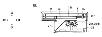
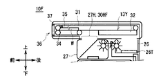
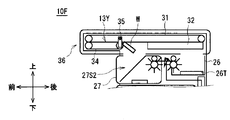
- the stacking unit 26 is located on the uppermost rear side in the storage case 20, and forms a stacking space 26S that is a space for stacking banknotes therein.
- the stacking unit 26 has a stage 26T for stacking banknotes on the upper surface in the stacking space 26S.
- the stage 26T is formed in a thin plate shape in the up-down direction, and the length in the front-rear direction and the length in the left-right direction are longer than the length of the short side and the long side of the bill, respectively.
- a discharge unit 26R that discharges the banknotes conveyed from the switching unit 25 into the stacking space 26S is provided on the upper front side of the stacking unit 26. Therefore, the stacking unit 26 can stack the banknotes conveyed from the switching unit 25 and discharged into the stacking space 26S by the discharge unit 26R on the stage 26T. At this time, the banknotes accumulated on the stage 26T are stacked in a bundle. Therefore, hereinafter, the banknotes stacked in this way are also referred to as banknote bundles.
- stage 26T can be moved up and down by a stage moving mechanism (not shown).
- An accumulation hole 26 ⁇ / b> H penetrating in the vertical direction is formed on the upper surface of the accumulation unit 26, that is, the surface facing the bundle conveyance unit 13.
- the length L1 in the front-rear direction of the accumulation hole 26H is slightly longer than the length in the front-rear direction of the stage 26T.
- the accumulation hole 26 ⁇ / b> H also penetrates the upper surface of the storage case 20, and connects the accumulation space 26 ⁇ / b> S and the space above the storage case 20.
- the stacking unit 26 moves the stage 26T upward in a state where banknotes are stacked on the stage 26T, so that the stage 26T and the stacked bundle of banknotes (banknote bundles) are more than the upper surface of the storage housing 20. Can be lifted up.
- the reject storage 27 is located on the uppermost front side in the storage case 20, and the internal space is divided into a first lower storage space 27S1 and a second upper storage space 27S2 by the partition plate 27P. It is delimited.
- the partition plate 27P is inclined with respect to the horizontal direction and the vertical direction.
- a release unit 27R that discharges the banknotes conveyed from the switching unit 25 into the first storage space 27S1 is provided at the rear upper side of the reject storage 27, that is, at a place communicating with the first storage space 27S1. Yes.
- the reject storage 27 can store the banknotes (that is, reject banknotes) conveyed from the switching unit 25 and discharged into the first storage space 27S1 by the discharge unit 27R.
- an intake hole 27H penetrating in the vertical direction is formed on the upper surface of the reject storage 27, that is, the surface facing the bundle transport unit 13.
- the length L4 in the front-rear direction in the intake hole 27H is substantially equal to the length L1 in the front-rear direction in the accumulation hole 26H of the accumulation portion 26.
- the intake hole 27 ⁇ / b> H also penetrates the upper surface of the storage housing 20, and connects the second storage space 27 ⁇ / b> S ⁇ b> 2 and the space above the storage housing 20. Therefore, the reject storage 27 can store the banknote in the second storage space 27S2 when the banknote falls from above.
- the reject storage 27 can be removed from the storage case 20 by being pulled forward with respect to the storage case 20 in the same manner as the banknote storage 21, and the position of the reject storage 27 is aligned with the storage case 20. Then, it can be attached to the housing case 20 by being pushed backward.
- the distance L2 from the case center line C1 to the accumulation hole 26H is the case center line. It is substantially the same as the distance L3 from C1 to the intake hole 27H. That is, the storage unit 12 has substantially the same lengths L1 and L4 in the front-rear direction representing the sizes of the collecting hole 26H and the intake hole 27H, and the lengths L2 and L3 representing the distance from the housing center line C1 are also almost equal. Therefore, the accumulation hole 26H and the intake hole 27H are formed almost symmetrically.
- the rear end portion of the accumulation hole 26H is defined as the accumulation hole end portion 26HE
- the front end portion of the intake hole 27H is defined as the intake hole end portion 27HE, and is further sandwiched between the accumulation hole end portion 26HE and the intake hole end portion 27HE.
- This range is defined as a hole range 20E.
- a virtual line representing the center in the front-rear direction in the hole range 20E is defined as a hole center line C2.
- the hole center line C2 coincides with the housing center line C1, and is located at the center of the hole range 20E, that is, the center of the range where the portions corresponding to the lengths L1 to L4 are connected.
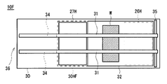
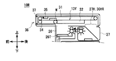
- FIG. 3 shows a state in which the detachable surface 12P of the storage unit 12 is directed to the front side, and the transport surface 12Q is directed to the rear side.
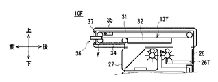
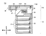
- the bundle transport unit 13 is formed in a flat rectangular parallelepiped shape that is short in the vertical direction and long in the front-rear direction as a whole, and the length in the front-rear direction is longer than that of the storage unit 12.
- the bundle conveyance unit 13 constitutes a bundle conveyance unit 13 ⁇ / b> C that conveys a banknote bundle in a rectangular parallelepiped bundle conveyance housing 30.
- the bundle conveyance unit 13C is configured by a combination of a plurality of mechanisms such as an upper belt 31, a holding conveyance guide 32, a lower belt 34, and an extrusion unit 35, and bundle conveyance that connects the vicinity of the front end and the vicinity of the rear end in the bundle conveyance housing 30.
- the banknote bundle W is conveyed along the path 13Y.
- the upper belt 31 is provided on the upper part in the bundle conveyance housing 30, that is, on the upper side of the bundle conveyance path 13Y.
- the upper belt 31 is wound around rollers disposed in the vicinity of the rear end and in the vicinity of the front end in the bundle transport housing 30, and the lower surface of the upper belt 31 is moved along the front-rear direction by rotating the roller. Let it run.
- the traveling direction of the lower surface portion of the upper belt 31 will be regarded as the traveling direction of the upper belt 31 below.
- a large hole portion 30 ⁇ / b> H having a large hole is formed in a wide range from the lower surface of the bundle conveyance housing 30 to the rear side in the front-rear direction.
- the length in the front-rear direction in the large hole portion 30H corresponds to the length obtained by adding the lengths L1, L2, L3, and L4 in the storage unit 12.
- the sandwiching conveyance guide 32 is provided in the range of the large hole portion 30 ⁇ / b> H in the lower portion of the bundle conveyance housing 30 than the upper belt 31.
- the nipping / conveying guide 32 is formed in a flat, rectangular parallelepiped shape or plate shape that is thin in the vertical direction, and its upper surface is opposed to or in contact with the lower surface of the upper belt 31.
- the length in the front-rear direction of the holding conveyance guide 32 corresponds to the length obtained by adding the lengths L2, L3, and L4 in the storage unit 12, or the length obtained by adding the lengths L1, L2, and L3. In other words, the length in the front-rear direction of the nipping and conveying guide 32 is shorter than the length in the front-rear direction of the large hole portion 30H by the length L1 or L4.
- the nipping and conveying guide 32 can be moved in the front-rear direction within the range of the large hole portion 30H by a moving mechanism (not shown).
- a moving mechanism not shown
- the nipping and conveying guide 32 moves to the front side, the vicinity of the center and the front side of the large hole portion 30H are closed, and a range corresponding to the length L1 on the rear side is opened.
- the portion opened to the rear side at this time is referred to as a rear passage hole 30HR.
- the nipping and conveying guide 32 moves to the rear side, the vicinity of the center and the rear side of the large hole portion 30H are closed, and the range corresponding to the length L4 on the front side is opened.
- the portion opened to the front side at this time is referred to as a front passage hole 30HF. That is, the length in the front-rear direction of the sandwiching conveyance guide 32 is shorter than the length in the front-rear direction of the large hole portion 30H by the length of the front passage hole 30HF or the length of the rear passage hole 30HR.
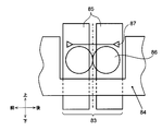
- the lower belt 34 is provided on the front side of the large hole portion 30H in the lower portion of the bundle conveying housing 30 than the upper belt 31.
- the lower belt 34 is configured such that the upper belt 31 is cut in the front-rear direction, and the upper surface of the lower belt 34 is opposed to or in contact with the lower surface of the upper belt 31 so as to run in the front-rear direction.
- the traveling direction of the upper surface portion of the lower belt 34 is considered as the traveling direction of the lower belt 34 below.
- the rear passage hole 30HR opened without being closed in the large hole portion 30H is when the stage 26T of the stacking portion 26 is moved upward. It is closed by the stage 26T.
- a bundle conveyance path 13 ⁇ / b> Y that is sandwiched from above and below by the upper belt 31, the stage 26 ⁇ / b> T, the nipping and conveying guide 32, and the lower belt 34 is formed.
- a part of the extruding portion 35 protrudes below the lower surface of the upper belt 31, and is moved along the front-rear direction, that is, along the bundle conveying path 13Y by a moving mechanism (not shown). Moreover, the extrusion part 35 can also be displaced to an up-down direction with the displacement mechanism which is not shown in figure. That is, as shown in FIG. 3, the push-out portion 35 is not only partially lowered below the lower surface of the upper belt 31, but also displaced upward from the lower surface of the upper belt 31 as will be described later. it can.
- the extruding part 35 protrudes downward from the lower surface of the upper belt 31 at only a few discrete points in the left-right direction.
- gaps or grooves along the front-rear direction are formed in the holding and conveying guide 32, the lower belt 34, and the stage 26T of the accumulating unit 26 in the storage unit 12 according to the extrusion unit 35. It is designed not to interfere.
- the pushing part 35 can push it forward and backward to advance it.
- the push-out unit 35 has a retracting mechanism (not shown) incorporated in the vicinity of the front end of the bundle conveyance path 13Y. For this reason, when the pushing part 35 is moved by the moving mechanism and reaches the vicinity of the front end, the pushing part 35 is rotated by the retracting mechanism and retracted above the bundle transport path 13Y, and does not interfere with the banknote bundle W.
- a withdrawal port 36 is formed to deliver the banknote bundle conveyed forward in the bundle conveyance path 13Y to the user.
- a sensor 37 for detecting the banknote bundle W is provided in the vicinity of the withdrawal port 36.
- the sensor 37 is configured by a combination of a light emitting element that emits predetermined detection light and a light receiving element that receives the detection light, and the optical path of the detection light intersects with the bundle conveyance path 13Y.
- the sensor 37 notifies the control unit 14 of the detection light reception result.
- the control unit 14 can determine whether or not there is a banknote bundle W at the withdrawal port 36 based on the light reception result.
- the withdrawal port 36 is mounted in the housing 2 of the cash dispenser 1 (FIG. 1), the withdrawal port 36 is located on the rear side (that is, inside) of the housing withdrawal port 5.
- the bill dispensing machine 10 is assembled by attaching the upper bundle transport unit 13 to the lower storage unit 12 at the time of manufacture.
- the bundle transport unit 13 has a direction in the banknote dispensing machine 10 in order to direct the dispensing port 36 toward the user.
- the storage unit 12 has the collecting hole 26H and the intake hole 27H formed substantially symmetrically in the front-rear direction within the hole range 20E, the mounting direction with respect to the bundle transport unit 13 can be switched between two ways.
- the banknote dispenser 10 directs the attachment / detachment surface 12P of the storage unit 12 to the front side, the transport surface 12Q to the rear side, and the intake hole 27H to the front passage hole 30HF.
- the stacking hole 26H is attached to the bundle transport unit 13 in a state where it is aligned with the rear passage hole 30HR.
- the banknote dispensing machine 10 is assembled in the state which can attach or detach the banknote storage 21 and the rejection storage 27 from the front side.
- the banknote dispensing machine 10 in which the detachable surface 12P is arranged on the front side in this way is also referred to as a front surface machine 10F.
- the intake hole 27H is closed, while the holding conveyance is performed.
- a rear passage hole 30HR is formed on the rear side of the guide 32 to open the accumulation hole 26H.
- the position of the holding conveyance guide 32 at this time is also referred to as a stacking release position.
- the collecting hole 26H is closed while the nipping and conveying guide 32 is closed.
- a front passage hole 30HF is formed on the front side of the gas and the intake hole 27H is opened.
- the position of the nipping and conveying guide 32 at this time is also referred to as a take-in and open position.
- the banknote dispensing machine 10 is opposite to the front and rear in the case shown in FIG. 3, with the attachment / detachment surface 12P of the storage unit 12 facing the rear side, the transport surface 12Q facing the front side, and the take-in hole 27H toward the rear passage hole 30HR.
- the stacking hole 26H is attached to the bundle transport unit 13 with the front passage hole 30HF being matched.
- the banknote dispensing machine 10 is assembled in the state which can attach or detach the banknote storage 21 and the rejection storage 27 from the rear side.
- the banknote dispensing machine 10 in which the detachable surface 12P is arranged on the rear side in this way is also referred to as a rear surface machine 10R.
- the nipping and conveying guide 32 is moved forward to close the accumulation hole 26H, and the front passage hole 30HF is formed on the front side to open the intake hole 27H. Is referred to as the intake open position.
- the holding conveyance guide 32 is moved rearward to close the intake hole 27H, and the rear passage hole 30HR is formed on the rear side to open the accumulation hole 26H. Called the open position.
- the banknote dispenser 10 reverses the mounting direction of the storage unit 12 with respect to the bundle transport unit 13 and switches the combination of the accumulation hole 26H and the intake hole 27H with the front passage hole 30HF and the rear passage hole 30HR.
- the front machine 10F and the rear machine 10R can be assembled in two ways. For this reason, the nipping and conveying guide 32 is arranged at the connection point between the storage unit 12 and the bundle conveying unit 13 when assembled as either the front machine 10F or the rear machine 10R.
- the front part of the housing 2 when the front machine 10F is incorporated, the front part of the housing 2 is configured as an openable / closable door, and the banknote storage 21 is opened with this door open. And the rejection storage 27 is attached or detached from the front side.
- the rear part of the housing 2 when the rear machine 10R is incorporated, the rear part of the housing 2 is configured as an openable / closable door, and the banknote storage 21 and the reject storage are opened with this door open. 27 is attached and detached from the rear side.
- the storage unit 12 in both the front surface machine 10 ⁇ / b> F and the rear surface machine 10 ⁇ / b> R, generally along the front-rear direction that is the direction along the bundle conveyance path 13 ⁇ / b> Y when attached to the bundle conveyance unit 13 on the upper side of the banknote storage 21.
- the stacking unit 26, the switching unit 25, and the reject storage 27 are arranged side by side.
- the banknote dispenser 10 stores a control program suitable for each configuration in the storage unit or the like of the control unit 14 according to whether the front unit 10F or the rear unit 10R is used during assembly. .
- the control unit 14 When the banknote dispensing machine 10 accepts a withdrawal instruction and a withdrawal amount from the user via the operation display unit 6 (FIG. 1), the control unit 14 reads the control program and the like while coordinating with the main control unit 9. To execute the process according to the configuration.
- the front unit 10F First, the front unit 10F will be described. As shown in FIG. 5A, the control unit 14 of the front surface machine 10F first moves the stage 26T downward, and moves the nipping and conveying guide 32 to the rear take-open position, thereby collecting the stacking holes 26H and the stacking unit 26H. The rear passage hole 30HR is closed. Moreover, the control part 14 moves the extrusion part 35 to the backmost side.
- control unit 14 sequentially feeds out the banknotes of the denomination and the number corresponding to the amount to be withdrawn from the banknote storage 21 by the feeding unit 22, transports it upward by the transporting unit 23, and discriminates it by the discrimination unit 24. At this time, based on the discrimination result obtained from the discrimination unit 24, the control unit 14 determines the transport destination as the stacking unit 26 or the reject storage box 27 depending on whether or not the discriminated banknote can be withdrawn. To do.
- control unit 14 transports the banknotes identified by the discrimination unit 24 forward and upward by the transport unit 23 to reach the switching unit 25.
- the switching unit 25 switches the advancing direction according to the conveyance destination determined for each bill, and advances the stacking unit 26 or the reject storage box 27.
- the stacking unit 26 discharges the conveyed banknotes into the stacking space 26S by the discharge unit 26R and stacks it on the stage 26T. At this time, since the upper part of the stacking hole 26H is closed by the holding and conveying guide 32, the stacking part 26 prevents the banknotes released from the discharging part 26R from rising upward and stably stacks on the stage 26T. be able to.
- the reject storage 27 discharges and stores the conveyed banknote into the first storage space 27S1 by the discharge unit 27R.
- the control unit 14 sequentially counts the denominations and the number of banknotes collected in the stacking unit 26 as the transport destination, that is, the banknote storage case when the total amount reaches the withdrawal amount. The delivery of bills from 21 is stopped. As a result, on the stage 26T of the stacking unit 26, the banknote bundle W in which the banknotes to be withdrawn are stacked in a bundle is placed.
- the control unit 14 moves the sandwiching conveyance guide 32 to the front stacking release position to open the stacking hole 26H and the rear passage hole 30HR of the stacking unit 26, and the intake hole 27H and After closing the front passage hole 30HF, the banknote bundle W is lifted by moving the stage 26T of the stacking unit 26 upward. Thereby, the stacking unit 26 can deliver the banknote bundle W from the storage unit 12 into the bundle transport unit 13 through the stacking hole 26H and the rear passage hole 30HR.
- control unit 14 aligns the upper surface of the stage 26T with the same height as the upper surface of the nipping and conveying guide 32, and configures a part of the bundle conveying path 13Y by the stage 26T, and the banknote bundle on the stage 26T. W is positioned in the bundle conveyance path 13Y.
- control unit 14 causes the banknote bundle W to be conveyed forward by the bundle conveyance unit 13C. Specifically, the control unit 14 advances the banknote bundle W forward along the bundle conveyance path 13Y by moving the upper belt 31 forward and moving the pusher 35 forward. At this time, when the banknote bundle W reaches a position where the banknote bundle W comes into contact with the upper surface of the lower belt 34, the controller 14 sandwiches the banknote bundle W from above and below by the upper belt 31 and the lower belt 34, and moves forward by the running of both belts. Transport.
- the control unit 14 stops the travel of the upper belt 31 and the lower belt 34 when detecting that the banknote bundle W has reached the dispensing port 36 based on the notification from the sensor 37.
- the control part 14 moves the stage 26T below at this time, and complete
- the control unit 14 causes the push-out unit 35 to reach the vicinity of the front end of the bundle conveyance path 13Y, and thereby retracts the bundle conveyance path 13Y above by a retraction mechanism (not shown).
- the front surface machine 10F exposes a part of the banknote bundle W from the withdrawal port 36, and sandwiches the vicinity of the rear end of the banknote bundle W by the upper belt 31 and the lower belt 34.
- the bundle W can be taken out.
- the control unit 14 monitors whether or not the banknote bundle W has been taken out from the withdrawal port 36 based on the notification from the sensor 37. Therefore, when the banknote bundle W is not taken out after a predetermined waiting time (for example, 30 seconds), that is, when forgetting to take out the banknote bundle W occurs, the control unit 14 takes in the banknote bundle W. Start operation.
- a predetermined waiting time for example, 30 seconds
- the bill that the user has forgotten to remove is also referred to as a forgotten bill.
- the control unit 14 first opens the front passage hole 30HF and the intake hole 27H by moving the nipping and conveying guide 32 to the rear intake / open position, and collects the accumulation holes 26H and 26H.
- the rear passage hole 30HR is closed.
- the control unit 14 causes the banknote bundle W to be conveyed backward by the bundle conveyance unit 13C.
- the control unit 14 causes the upper belt 31 and the lower belt 34 to travel rearward while the pushing unit 35 is retracted upward, thereby taking the banknote bundle W into the bundle conveyance path 13Y, and the bundle conveyance path 13Y. Proceed backwards along.
- the control unit 14 detects that the banknote bundle W has arrived rearward of the pusher part 35 by a sensor (not shown), the pusher part 35 that has been retracted above the bundle transport path 13Y is moved to the front side of the banknote bundle W. After returning to the bundle conveyance path 13Y, the bill bundle W is further conveyed backward by moving it further backward.
- the control unit 14 drops the banknote bundle W from the bundle conveyance path 13Y, and the front passage hole 30HF and the pickup Through the insertion hole 27H, the storage is performed in the second storage space 27S2 of the reject storage 27, and the capturing operation is completed.
- the front surface machine 10F can take in the banknote bundle W that the user has forgotten to take out from the withdrawal port 36 and store it in the reject storage 27.
- the control unit 14 of the rear machine 10R first moves the stage 26T downward, and moves the nipping and conveying guide 32 to the front take-off position, thereby collecting the stacking unit 26.
- the collecting hole 26H and the front passage hole 30HF are closed, and the intake hole 27H and the rear passage hole 30HR are opened.
- the control unit 14 moves the pushing unit 35 to a position slightly behind the stage 26T. In this state, similarly to the case of the front surface machine 10F, the control unit 14 conveys the banknotes corresponding to the withdrawal amount to the stacking unit 26 and stacks them on the stage 26T to form the banknote bundle W.
- the control unit 14 moves the clamping conveyance guide 32 to the rear stacking release position to open the stacking hole 26H and the front passage hole 30HF of the stacking unit 26, and the intake hole 27H and After closing the rear passage hole 30HR, the banknote bundle W is lifted by moving the stage 26T of the stacking unit 26 upward.
- the stacking unit 26 can deliver the banknote bundle W from the storage unit 12 into the bundle transport unit 13 through the stacking hole 26H and the front passage hole 30HF.
- the control unit 14 aligns the upper surface of the stage 26T to the same height as the upper surface of the lower belt 34, and configures a part of the bundle transport path 13Y by the stage 26T, and the banknote bundle W on the stage 26T. Is positioned in the bundle conveying path 13Y.
- control unit 14 also transports the banknote bundle W forward by the bundle transport unit 13C, similarly to the front surface machine 10F. Specifically, the control unit 14 moves the upper belt 31 and the lower belt 34 forward and moves the pushing unit 35 forward to advance the banknote bundle W forward along the bundle conveyance path 13Y. As shown, the banknote bundle W is made to reach the withdrawal port 36. Incidentally, the control part 14 moves the stage 26T below at this time, and complete
- the rear surface machine 10R like the front surface machine 10F, exposes a part of the banknote bundle W from the withdrawal port 36 and holds the vicinity of the rear end of the banknote bundle W by the upper belt 31 and the lower belt 34.
- the banknote bundle W can be taken out by the user.
- the control unit 14 starts the taking-in operation of taking in the banknote bundle W as in the case of the front unit 10F. Specifically, as shown in FIG. 8A corresponding to FIG. 6A, the control unit 14 first closes the front passage hole 30HF and the accumulation hole 26H by moving the nipping and conveying guide 32 to the front intake / open position. The rear passage hole 30HR and the intake hole 27H are opened. Moreover, the control part 14 conveys the banknote bundle W back by the bundle conveyance part 13C similarly to the case of the front surface machine 10F.
- control unit 14 temporarily displaces the push-out unit 35 to cause the upper belt 31 and the lower belt 34 to travel rearward, and displaces the push-out unit 35 downward and moves it backward.
- the control part 14 takes in the banknote bundle W in the bundle conveyance path 13Y, and advances it back along the said bundle conveyance path 13Y.
- the control unit 14 drops the banknote bundle W from the bundle transport path 13Y as shown in FIG.
- the take-in operation is completed after being stored in the storage space 27S2.
- the rear surface machine 10 ⁇ / b> R can take in the banknote bundle W that the user has forgotten to remove from the withdrawal port 36 and store it in the reject storage 27.
- the dispensing operation and the taking-in operation in the rear surface machine 10R are substantially the same as the operations until the banknote bundle W is generated in the storage unit 12 as compared with the case of the front surface machine 10F.
- the operation of conveying the banknote bundle W is partially different.
- the control unit 14 changes the control related to the movement of the nipping and conveying guide 32 and the movement of the pushing unit 35 between the case of the front machine 10F and the case of the rear machine 10R.
- the banknote dispensing machine 10 is configured to attach the lower storage unit 12 to the upper bundle transport unit 13.
- the size of the hole range 20E provided in the upper part of the storage unit 12 and the large hole part 30H formed in the lower surface of the bundle conveying unit 13, that is, the length in the front-rear direction are substantially aligned. Further, the banknote dispenser 10 forms the accumulation hole 26H and the intake hole 27H in the hole range 20E in the storage unit 12 substantially symmetrically in the front-rear direction, and is further formed in the bundle conveyance unit 13 in accordance with the movement of the pinch conveyance guide 32.
- the positions and sizes of the front passage hole 30HF and the rear passage hole 30HR corresponded to the accumulation hole 26H and the intake hole 27H, respectively (FIG. 3).
- a banknote bundle conveyance path is formed only on the front side of the forgotten banknote storage unit 16 (FIG. 1). It was.
- the banknote dispensing machine 10 is configured such that the bundle conveyance path 13Y passes above the reject storage 27.
- the banknote dispenser 10 has the detachable surface 12P of the storage unit 12 facing the front side or the rear side, and the stacking hole 26H and the intake hole 27H are respectively bundled with either the front passage hole 30HF or the rear passage hole 30HR.
- the transport unit 13 By attaching to the transport unit 13, it is possible to assemble the front machine 10F and the rear machine 10R in two ways (FIG. 2).
- the front face machine 10F (FIG. 2A) has the withdrawal port 36 positioned on the front side, and can attach and detach the banknote storage 21 and the reject storage 27 from the attachment / detachment surface 12P which is the front of the storage unit 12, respectively.
- the dispensing operation and the taking-in operation can be performed while delivering the banknote bundle W between 12 and the bundle conveying unit 13 (FIGS. 5 and 6).
- the rear surface machine 10R (FIG. 2B) has the withdrawal port 36 positioned on the front side, and can detach the bill storage 21 and the reject storage 27 from the attachment / detachment surface 12P which is the rear surface of the storage unit 12, respectively.
- the banknote dispensing machine 10 can be assembled as either the front machine 10F or the rear machine 10R depending on the installation location, etc. Withdrawing and taking in can be performed. That is, since the banknote dispensing machine 10 can operate as both the front machine 10F and the rear machine 10R, it is possible to eliminate restrictions on the installation location. In addition, the banknote dispensing machine 10 can share parts and modules in common, and can greatly reduce the cost required for manufacturing and management compared to the case where the front machine and the rear machine are designed separately. .
- the bundle transport unit 13 forms a large hole portion 30H having a size including the collecting hole 26H and the intake hole 27H, and a part thereof is closed by the sandwiching transport guide 32 so that the remaining portion is blocked by the front passage hole. 30HF or rear passage hole 30HR.
- the bundle transport unit 13 moves the nipping and conveying guide 32 to the accumulation opening position or the taking-in opening position by a simple operation such as moving the nipping and conveying guide 32 in the front-rear direction, and the front passage hole 30HF and the rear passage hole.
- One of 30HR can be opened and the other can be closed simultaneously.
- the banknote dispenser 10 pushes the banknote bundle W in the front-rear direction by the push-out section 35 in the bundle transport section 13C of the bundle transport unit 13, and moves it in the front-rear direction along the bundle transport path 13Y.
- banknotes can be transported without incorporating a belt mechanism such as the lower belt 34 into the clamping transport guide 32 and the stage 26 ⁇ / b> T, so that the configuration can be greatly simplified.
- the banknote dispensing machine 10 is provided with a lower belt 34 formed of a belt mechanism in front of the nipping and conveying guide 32 in the bundle conveying unit 13C of the bundle conveying unit 13.
- the banknote dispenser 10 can stably take in the banknote bundle W in comparison with the case where a plate-like member such as the holding conveyance guide 32 is provided instead of the lower belt 34.
- the banknote dispensing machine 10 is provided with the lower belt 34 formed of a belt mechanism only in the vicinity of the dispensing port 36, and the sandwich conveyance guide 32 and the stage 26T located at other locations are simply plate-like members.
- the accuracy and stability in the taking-in operation of the banknote bundle W can be improved, and at the same time, the configuration can be simplified as much as possible to reduce the cost.
- the banknote dispensing machine 10 After distinguishing a banknote by the discrimination part 24 on the structure, a conveyance destination is determined according to the discrimination result in the control part 14, and also the switching operation of the advancing direction is further performed in the switching part 25. It will take some time to complete. For this reason, in the banknote dispenser 10, if the transport distance from the discrimination unit 24 to the switching unit 25 is short, it is necessary to reduce the banknote transport speed in order to wait for the switching operation in the switching unit 25 to be completed. As a result, the time required for completing the dispensing operation can be increased.
- the banknote dispensing machine 10 can form the transport path from the discrimination unit 24 to the switching unit 25 to be somewhat long by arranging the switching unit 25 in the front and rear direction in the storage unit 12. For this reason, in the banknote dispenser 10, since the switching operation of the advancing direction in the said switching part 25 can be completed while conveying a banknote from the discrimination part 24 to the switching part 25, it is necessary to reduce the conveyance speed of a banknote unnecessarily. The withdrawal operation can be completed in a short time.
- the switching unit 25 since the switching unit 25 is arranged between the stacking unit 26 and the reject storage 27, the conveyance path length from the discrimination unit 24 to the stacking unit 26 via the switching unit 25 is The conveyance path length from the discrimination unit 24 to the reject storage 27 via the switching unit 25 can be equally set. Thereby, in the banknote dispensing machine 10, the conveyance path
- the banknote dispenser 10 has the feeding unit 22 provided in the lower rear portion of the banknote storage 21 in the storage unit 12, so that the position at which the banknote 23 starts to be transported upward is relatively positioned below. Can do.
- the banknote dispensing machine 10 can arrange
- the conveyance path from the unit 24 to the switching unit 25 can be made sufficiently long.
- the banknote dispensing machine 10 forms the accumulation holes 26H and the intake holes 27H in the storage unit 12 almost symmetrically in the front-rear direction, and the front passage hole of the bundle transport unit 13 30HF and the rear passage hole 30HR were formed at positions corresponding to these.
- the banknote dispenser 10 has the detachable surface 12P of the storage unit 12 facing the front side or the rear side, and the stacking hole 26H and the intake hole 27H are respectively bundled with either the front passage hole 30HF or the rear passage hole 30HR.
- the banknote dispenser 10 can eliminate the restriction of the installation place, and can reduce the cost required for manufacturing and management by sharing parts and modules.
- the banknote dispenser 110 As shown in FIG. 9A corresponding to FIG. 2A, the banknote dispenser 110 according to the second embodiment is roughly composed of a main body unit 112 on the rear side and a unit 113 on the front side of the bundle conveyance, A control unit 114 for controlling the whole is incorporated. Similar to the control unit 14, the control unit 114 is mainly configured by a CPU (not shown) and performs processing such as a withdrawal process. The control unit 14 stores various information in a built-in storage unit.
- the main body unit 112 is configured such that the storage unit 12 in the first embodiment and a portion corresponding to a range of about 2/3 of the rear side of the bundle transport unit 13 are combined.
- the lower portion of the main unit 112, that is, the portion corresponding to the storage unit 12 is a storage unit 117.
- the storage unit 117 includes the same storage case 20, banknote storage 21 (21A, 21B, 21C, and 21D) as the storage unit 12, a transport unit 23, a discrimination unit 24, a switching unit 25, and a reject storage 27.
- An accumulation unit 126 is provided in place of the accumulation unit 26.
- a belt mechanism similar to the lower belt 34 and the like is incorporated in the stage 126T.
- the upper part of the main body unit 112 that is, the part corresponding to the range of about 2/3 of the rear side of the bundle transport unit 13 is the post-bundle transport unit 118.
- a bundle transport unit 118 ⁇ / b> C is incorporated in the post-batch transport housing 130 corresponding to the rear portion of the bundle transport housing 30.
- the bundle conveyance unit 118C is provided with an upper rear belt 131 and a movable conveyance belt 132 corresponding to the upper belt 31 and the holding conveyance guide 32, respectively, as compared with the rear portion of the bundle conveyance unit 13C, while the extrusion unit 35 It is omitted.
- the post-bundle transport housing 130 corresponds to a range of about 2/3 of the rear side of the bundle transport housing 30 in the first embodiment, and the first embodiment covers almost the entire lower surface thereof. A large hole 30H similar to the above is formed.
- the upper rear belt 131 is configured such that the front roller of the upper belt 31 in the first embodiment is retracted to the vicinity of the front end of the housing 130 after the bundle conveyance to shorten the circumferential length of the belt. .
- the movable conveyance belt 132 has a length in the front-rear direction corresponding to the sum of the lengths L1, L2, and L3 in the same manner as the sandwich conveyance guide 32, and is within the range of the large hole 30H by a moving mechanism (not shown). You can move forward and backward. Further, the movable conveyance belt 132 incorporates a belt mechanism, and can travel on the upper surface in the front-rear direction.
- a bundle conveyance path 118Y for conveying the banknote bundle W in the front-rear direction is formed by the bundle conveyance unit 118C along the lower surface of the upper rear belt 131.
- delivery ports 130P and 130Q for delivering the banknote bundle W are formed at the front and rear ends of the post-bundle casing 130, that is, at the front and rear ends of the bundle transport path 118Y.
- the main unit 112 is different from the first embodiment in that the mounting direction of the post-bundle transport unit 118 with respect to the storage unit 117 is fixed. Further, for convenience of explanation, the surface of the main unit 112 on which the banknote storage 21 can be attached / detached is referred to as an attaching / detaching surface 112P, and the surface in which the transport unit 23 is incorporated is referred to as a transport surface 112Q. That is, the post-bundle transport unit 118 is attached to the storage unit 117 with the delivery port 130P facing the attachment / detachment surface 112P and the delivery port 130Q facing the transport surface 112Q.
- the unit 113 before bundle conveyance corresponds to a range of about 1/3 of the front side of the bundle conveyance unit 13 in the first embodiment.
- a bundle conveyance unit 113 ⁇ / b> C is incorporated in a case 140 before bundle conveyance corresponding to the front portion of the bundle conveyance case 30.
- the bundle conveyance unit 113C is provided with an upper front belt 141 in place of the upper belt 31 in addition to the lower belt 34, as compared with the front side portion of the bundle conveyance unit 13C.
- the housing 140 before bundle conveyance corresponds to a range of about 3 of the front side of the bundle conveyance housing 30 in the first embodiment, and has a withdrawal port 36 at the front end and a sensor 37 in the vicinity thereof. Is provided.
- the upper front belt 141 corresponds to a range of about one third of the upper belt 31 in the first embodiment, and like the upper belt 31, the upper front belt 141 wraps around the rollers arranged at the front and rear. By rotating the belt, the lower surface of the belt travels in the front-rear direction.
- the bundle conveyance path 113Y for conveying the banknote bundle W in the front-rear direction is formed in the unit 113 before bundle conveyance by the bundle conveyance unit 113C along the lower surface of the upper front belt 141.
- a delivery port 140M for delivering the banknote bundle W is formed at the rear end of the pre-bundling housing 140, that is, the rear end of the bundle conveyance path 113Y.
- the banknote dispenser 110 can attach the unit 113 before bundle conveyance to either the attachment / detachment surface 112P or the conveyance surface 112Q of the main unit 112.
- the banknote dispenser 110 attaches the bundle pre-conveyance unit 113 with the attachment / detachment surface 112P of the main unit 112 facing the front side, the transport surface 112Q facing the rear side, and the delivery port 140M facing the delivery port 130P.
- the banknote dispensing machine 10 is assembled in the state which can attach or detach the banknote storage 21 from the front side.
- the banknote dispenser 110 in which the detachable surface 112P is arranged on the front side in this way is also referred to as a front unit 110F.
- the banknote dispenser 110 attaches the unit 113 before bundle conveyance with the attaching / detaching surface 112P of the main body unit 112 facing rearward, the transporting surface 112Q facing frontward, and the delivery port 140M facing the delivery port 130Q. .
- the banknote dispenser 10 is assembled in the state which can attach or detach the banknote storage 21 from the rear side.
- the banknote dispenser 110 in which the detachable surface 112P is arranged on the rear side is also referred to as a rear surface device 110R.
- the banknote dispensing machine 110 reverses the mounting direction of the main body unit 112 with respect to the unit 113 before bundle conveyance and makes the delivery port 140M face the delivery port 130P or the delivery port 130Q, thereby making the front machine 110F and the rear machine 110R. It can be assembled in two ways.
- the post-bundle transport unit 118 and the pre-bundle transport unit 113 cause the upper rear belt 131, the upper front belt 141, the belt incorporated in the stage 126T, the movable transport belt 132, and the lower belt 34 to run forward or backward, respectively.
- the banknote bundle W is transported along the bundle transport paths 118Y and 113Y.
- the banknote dispensing machine 110 can perform the dispensing operation and the taking-in operation in any of the front unit 110F and the rear unit 110R, similarly to the banknote dispensing machine 10 according to the first embodiment.
- the post-bundle transport unit 118 arranges the delivery port 130P and the delivery port 130Q that can deliver the banknote bundle W to and from the delivery port 140M symmetrically in the front-rear direction, and the upper rear belt 131 and the movable transport belt 132. And the banknote bundle W can be conveyed along the front-back direction by the stage 126T. Further, the post-bundle transport unit 118 moves the banknote bundle W to be withdrawn to the bundle transport path 118Y by the stage 126T, and drops the stored banknote bundle W into the reject storage 27 for storage.
- the banknote dispenser 110 is configured such that the pre-bundle transport unit 113 and the post-bundle transport unit 118 are connected regardless of whether the pre-bundle transport unit 113 is attached to either the attachment / detachment surface 112P side or the transport surface 112Q side of the main body unit 112. While delivering the banknote bundle W, the dispensing operation and the taking-in operation can be performed correctly.
- the banknote dispensing machine 110 is configured to transport the banknote bundle W back and forth along the bundle transport path 118Y in the post-bundle transport unit 118, and is provided at both front and rear ends. Both the delivery port 130P and the delivery port 130Q can deliver the banknote bundle W between the delivery port 140M of the unit 113 before bundle conveyance. For this reason, the banknote dispenser 110 is attached to the pre-bundle conveyance unit 113 with the attachment / detachment surface 112P of the main body unit 112 facing the front side or the rear side and either the delivery port 130P or the delivery port 130Q facing the delivery port 140M.
- the front machine 110F and the rear machine 110R can be assembled in two ways. Thereby, the banknote dispenser 110 can eliminate the restriction of the installation location, and can reduce the cost required for manufacturing and management by sharing parts and modules.
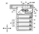
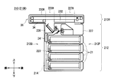
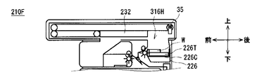
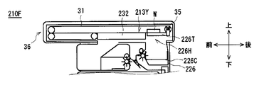
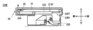
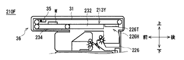
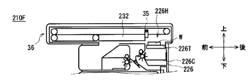
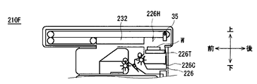
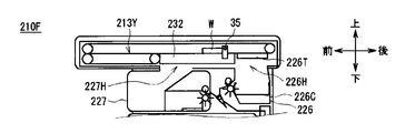
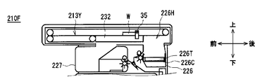
- FIG. 11 corresponding to FIG. 2 and FIG. 9, the banknote dispensing machine 210 according to the third embodiment is roughly divided into a lower storage unit 212 and an upper bundle transport unit 213 (213F, 213R). Further, a control unit 214 for controlling the whole is incorporated. Similar to the control unit 14, the control unit 214 is configured around a CPU (not shown) and performs processing such as a withdrawal process. The control unit 214 stores various information in a built-in storage unit.
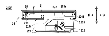
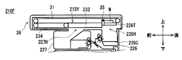
- the storage unit 212 is configured in substantially the same manner as the storage unit 12 according to the first embodiment, but is partially different in configuration. Specifically, the storage unit 212 is replaced with a storage case 220, a transfer unit 223, a stacking unit 226, and a reject storage 227 instead of the storage case 20, the transfer unit 23, the stacking unit 26, and the reject storage 27 of the storage unit 12. And a nipping and conveying guide 232 is further provided.
- the accumulating unit 226 has a slightly shorter front-rear length than the accumulating unit 26 according to the first embodiment.
- the reject storage 227 has a slightly longer front-rear length than the reject storage 27 according to the first embodiment.
- the switching unit 25 is disposed at a position deviated from the housing center line C1 representing the center in the front-rear direction of the storage housing 220, that is, toward the transport surface 212Q.
- route of a banknote is partly different from the conveyance part 23 by 1st Embodiment. That is, the conveyance unit 223 is formed with an inclined portion in the portion that passes through the discrimination unit 24 and goes to the switching unit 25, and moves from the switching unit 25 to the reject storage 227 so as to substantially maintain this inclination angle. The part is also partly inclined. Further, a portion of the transport unit 223 toward the stacking unit 226 once travels upward and is curved backward from the middle.
- the accumulation portion 226 has an accumulation hole 226H penetrating in the vertical direction on the upper surface thereof.
- the length of the accumulation hole 226H in the front-rear direction is the length L1 as in the first embodiment.
- the stacking unit 226 is provided with a stacking unit 226C in addition to the discharge unit 26R similar to that in the first embodiment, the stage 226T corresponding to the stage 26T in the first embodiment.
- the stacking basket 226C is formed in a box shape with an open upper surface, and the stage 226T is accommodated in the inner stacking space 226S, and banknotes are stacked on the upper surface of the stage 226T.
- the accumulation rod 226C is rotated by a rotation mechanism (not shown) and transitions to an inclined posture in which the stage 226T is inclined as shown in FIG. 12, or a horizontal posture in which the stage 226T is substantially horizontal as will be described later. Can do.
- the inclination angle of the stage 226T with respect to the horizontal direction is larger (that is, close to the vertical) than the discharge angle of the banknotes discharged to the accumulation space 226S by the discharge unit 26R.
- the stage 226T can be moved up and down with respect to the stacking basket 226C by a moving mechanism (not shown).
- the reject storage 227 is provided with a take-in hole 227H penetrating in the vertical direction at the rear of the upper surface thereof, that is, at a position close to the switching unit 25 and the stacking unit 226.
- the length in the front-rear direction of the intake hole 227H is the length L4, similar to the intake hole 27H in the first embodiment, and is equal to the length L1 of the accumulation hole 226H.
- the first storage space 227S1 and the second storage space 227S2 are formed by dividing the space by a plurality of partition plates 227P.
- the first storage space 227S1 is provided on the rear side in the reject storage 227, that is, on the side close to the switching unit 25, substantially directly below the intake hole 227H, and is adjacent to the discharge unit 27R.
- the reject storage 227 like the first storage space 27S1 in the first embodiment, receives banknotes (that is, reject banknotes) conveyed from the switching unit 25 and discharged into the first storage space 227S1 by the discharge unit 27R. And can be stored in the first storage space 227S1.
- the second storage space 227S2 is provided on the front side in the reject storage 227, that is, on the side close to the detachable surface 12P, and communicates with the intake hole 227H on the upper oblique rear side.
- An inclined surface 227L is formed below the intake hole 227H and above the first storage space 227S1.
- the inclined surface 227L is high on the rear side, that is, on the side close to the switching unit 25 and the stacking unit 226, and low on the front side, that is, on the side close to the detachable surface 212P.
- the reject storage 227 guides the banknote bundle W forward along the inclined surface 227L, and the second storage in the first embodiment. Similar to the space 27S2, it can be stored in the second storage space 227S2.
- the rear end portion of the accumulation hole 226H is defined as the accumulation hole end portion 226HE
- the front end portion of the intake hole 227H is defined as the intake hole end portion 227HE
- the accumulation hole end portion 226HE A range sandwiched by the intake hole end portion 227HE is defined as a hole range 220E.
- the hole center line C2 representing the center of the hole range 220E is offset from the housing center line C1 representing the center in the front-rear direction of the storage housing 220 toward the transport surface 212Q.
- the hole range 220 ⁇ / b> E is provided at a position that is asymmetrical with respect to the housing 220.
- the clamping conveyance guide 232 corresponds to the clamping conveyance guide 32 provided in the bundle conveyance unit 13 in the first embodiment, and is formed in a plate shape that is thin in the vertical direction and long in the front-rear direction.
- the length in the front-rear direction of the holding conveyance guide 232 corresponds to the length obtained by adding the lengths L2, L3, and L4 or the length obtained by adding the lengths L1, L2, and L3, as in the first embodiment. This corresponds to the length excluding either the accumulation hole 226H or the intake hole 227H from the hole range 220E.
- This clamping conveyance guide 232 can be moved in the front-rear direction within the range of the hole range 220E by a moving mechanism (not shown) as in the first embodiment. That is, when the nipping / conveying guide 232 moves to the rear take-off position as shown in FIG. 12, it opens the take-in hole 227H and closes the stack hole 226H. Is moved, the accumulation hole 226H is opened and the intake hole 227H is closed. Further, the nipping and conveying guide 232 constitutes a part of the bundle conveying unit 213C as will be described later.
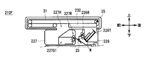
- two types of bundle conveying units 213 such as a front surface bundle conveying unit 213F and a rear surface bundle conveying unit 213R are prepared, and either one of them is combined with the storage unit 212 to obtain the front unit 210F or The rear machine 210R is configured.
- the front-side bundle conveyance unit 213F will be described as an example.
- the front-side bundle conveyance unit 213F constitutes a bundle conveyance unit 213C that replaces the bundle conveyance unit 13C as compared with the bundle conveyance unit 213 according to the first embodiment, and the bundle instead of the bundle conveyance housing 30 and the lower belt 34.
- the conveyance housing 230F and the lower belt 234 are provided and the nipping conveyance guide 32 is omitted, the other configurations are the same.
- the bundle conveyance unit 213C forms a bundle conveyance path 213Y in the bundle conveyance case 230F by the nipping conveyance guide 232 of the storage unit 212 in addition to the upper belt 31, the lower belt 234, and the extrusion unit 35.
- the bundle transport housing 230F is different from the bundle transport housing 30 according to the first embodiment in that it has a large hole portion 230H instead of the large hole portion 30H, but is configured similarly in other points. Has been.
- the position and size of the large hole portion 230H are adjusted so as to correspond to the hole range 220E in the storage unit 212 (FIG. 12) with the attachment / detachment surface 212P facing forward.
- the lower belt 234 has a configuration in which the lower belt 34 according to the first embodiment is extended rearward, and the rear end thereof reaches the vicinity of the front end of the large hole portion 230H.
- the rear bundle conveying unit 213R (FIG. 11B) has a large hole portion 230H formed in front of the front bundle conveying unit 213F, and is not the lower belt 234 but the same as in the first embodiment.
- the lower belt 34 is different in that it is used.
- the control unit 214 of the banknote dispensing machine 210 places the stacking basket 226C and the stage 226T in an inclined posture in the stacking unit 226. Similarly to the first embodiment, the control unit 214 moves the nipping and conveying guide 232 to the rear take-off and open position to open the take-in hole 227H and close the accumulation hole 226H, thereby Move to the rearmost side. Similarly to the case shown in FIG. 5A, the control unit 214 stores the banknotes fed from the banknote storage 21 by the feeding unit 22 through the discrimination unit 24 and the switching unit 25 by the transport unit 223, or the stacking unit 226 or reject storage. It is conveyed to the warehouse 227.
- the stacking unit 226 discharges the conveyed banknotes into the stacking space 226S by the discharge unit 26R, and sequentially stacks them on the stage 226T in the stacking basket 226C. At this time, the banknotes are arranged in a state where they are in contact with the front side surface of the stacking basket 226C and the like on the stage 226T by the action of gravity. In addition, the reject storage 227 releases and stores the conveyed banknotes into the first storage space 227S1 by the discharge unit 27R.
- the control unit 214 moves the nipping and conveying guide 232 to the front accumulation opening position as shown in FIG. 13B, and then horizontally moves the accumulation basket 226C.
- the upper surface of the stage 226T is made almost horizontal.
- the control unit 214 raises the stage 226T, thereby delivering the banknote bundle W into the front-side bundle transport unit 213F through the stacking hole 226H, and transporting the banknote bundle W in bundles. Position on the path 213Y.
- the stage 226T forms a part of the bundle conveyance path 213Y.
- the control unit 214 transports the banknote bundle W forward by the bundle transport unit 213C, as in the first embodiment. Specifically, the control unit 214 advances the banknote bundle W forward along the bundle conveyance path 213 ⁇ / b> Y by causing the upper belt 31 to travel forward and moving the pushing unit 35 forward. At this time, when the banknote bundle W reaches a position where the banknote bundle W comes into contact with the upper surface of the lower belt 234, the controller 214 sandwiches the banknote bundle W from above and below by the upper belt 31 and the lower belt 234, and moves forward by the running of both belts. Transport.
- the control unit 214 stops the running of the upper belt 31 and the lower belt 234, finishes the withdrawal operation, and is taken out by the user. Make it. Further, the control unit 214 causes the push-out unit 35 to reach the vicinity of the front end of the bundle conveyance path 213Y, thereby retracting it above the bundle conveyance path 213Y by a retraction mechanism (not shown).
- the control unit 214 when the banknote bundle W is not taken out from the withdrawal port 36, the control unit 214 performs a take-in operation for taking in the banknote bundle W according to a procedure different from that of the first embodiment. Specifically, the control unit 214 first transports the banknote bundle W backward by the bundle transport unit 213C. That is, as shown in FIG. 13E, the control unit 214 causes the upper belt 31 and the lower belt 234 to travel rearward while the push-out unit 35 is retracted upward, thereby bringing the banknote bundle W into the bundle conveyance path 213Y. Taking in and moving backward along the bundle conveying path 213Y.
- the control unit 214 detects that the banknote bundle W has reached the rear of the push-out section 35 by a sensor (not shown), as shown in FIG. 14A, the banknote bundle W retreated above the bundle transport path 13Y. After the sheet is returned to the bundle conveyance path 13Y on the front side, the sheet bundle W is further moved backward to assist the conveyance of the banknote bundle W to the rear.
- the control unit 214 continues to push the banknote bundle W backward by the extruding unit 35, and the banknote bundle W is moved to the stage 226T as shown in FIG. 14B.
- the pushing part 35 is stopped at the stage where it is placed on. That is, the control unit 214 moves the banknote bundle W to the rear side of the intake hole 227H of the reject storage 227.
- the control unit 214 lowers the stage 226T in a state where the banknote bundle W is placed, thereby temporarily separating the banknote bundle W from the bundle transport path 213Y. Subsequently, as shown in FIGS. 14D and 14E, the control unit 214 moves the pushing unit 35 to the vicinity of the rear end of the bundle conveying path 213Y without contacting the banknote bundle W, and then raises the stage 226T. The banknote bundle W is returned again into the bundle conveyance path 213Y. As a result, the pushing unit 35 is positioned on the rear side of the banknote bundle W in the bundle conveyance path 213Y. That is, the control unit 214 can move the pushing unit 35 from the front side to the rear side of the banknote bundle W by using the movement of the banknote bundle W in the vertical direction by the stage 226T.
- the control unit 214 transports the banknote bundle W forward by the bundle transport unit 213C. Specifically, as shown in FIGS. 15A, 15B, and 15C, the control unit 214 moves the push-out unit 35 forward so that the banknote bundle W is positioned on the upper surface of the holding conveyance guide 32 and through the intake hole 227H. After the sheet is conveyed to the rear side, the stage 226T is lowered, and the nipping and conveying guide 232 is moved to the rear take-off and opening position while the pusher 35 is stopped. Thereby, the control part 214 can open the taking-in hole 227H, position the banknote bundle W on the rear side of the taking-in hole 227H, and bring the pushing part 35 into contact with the rear side.
- control unit 214 moves the push-out unit 35 forward to drop the banknote bundle W into the take-in hole 227H and slide it forward along the inclined surface 227L.
- the control unit 214 can guide and store the banknote bundle W that the user has forgotten to take into the second storage space 227S2 while sliding along the inclined surface 227L.
- the banknote dispensing machine 210 moves the holding and conveying guide 232 in the front-rear direction inside the hole range 220E in the storage unit 212, whereby the stacking hole 226H and the taking-in hole 227H. Either one of them was opened. Further, the banknote dispenser 210 has a front bundle transport unit 213F for the front machine 210F and a rear bundle transport unit 213R for the rear machine 210R that are different from each other mainly with respect to the position of the large hole portion 230H. .
- the storage unit 212 of the banknote dispenser 210 can be incorporated into either the front unit 210F or the rear unit 210R by simply switching the mounting direction with respect to the bundle transport unit 213.
- the banknote dispensing machine 210 shares parts at an extremely high rate between the front surface machine 210F and the rear surface machine 210R as compared with the case of the conventional banknote dispensing machine described in Japanese Patent No. 5156097.
- the banknote dispenser 210 moves the banknote bundle W to the rear side of the take-in hole 227H, that is, the higher side of the inclined surface 227L, particularly when the banknote bundle W that the user forgets to take in the front machine 210F. It was made to fall after. Thereby, the banknote dispenser 210 stores the banknote bundle W collected in a bundle shape by reaching the second storage space 227S2 while maintaining the state of being bundled as much as possible without greatly breaking during dropping. be able to.
- the switching unit 25 is positioned closer to the transport surface 212Q than the housing center line C1 that represents the front and rear center of the storage housing 220.
- the storage unit 212 determines the length of the conveyance path when the banknote that has passed through the discrimination unit 24 by the conveyance unit 223 is conveyed to the stacking unit 226 in the case of the storage unit 12 (FIG. 3) according to the first embodiment. Can be shortened.
- the frequency of generation of reject banknotes in the discrimination unit 24 is extremely low, and most banknotes are conveyed to the stacking unit 226 as normal banknotes. For this reason, in the storage unit 212, it is possible to reduce the possibility that the banknotes may be jammed during the conveyance as the conveyance path to the stacking unit 226 through which many banknotes are conveyed is shortened.
- the transport unit 223 of the storage unit 212 has almost no change in the advancing direction when passing through the switching unit 25 in the transport route of banknotes from the discrimination unit 24 to the reject storage 227, and the transport path is curved.
- the angle is also an obtuse angle in the part where it is done.
- the storage unit 212 may change the traveling direction within a relatively small angle range, and adds the banknote being transported.
- the load can be kept relatively small and can be stably conveyed.
- the tilt angle of the stage 226T with respect to the horizontal direction is relatively large, and in particular, larger than the banknote discharge angle discharged from the discharge unit 26R into the stacking space 226S (FIG. 12).
- gravity can be applied to the banknotes released from the discharge unit 26R, and the front end side of each banknote can be brought into contact with the side surface of the stacking basket 226C and the like, and can be arranged on the stage 226T.
- banknote dispensing machine 210 is otherwise different from the banknote dispensing machine 10 according to the first embodiment except that the configurations of the front surface bundle transport unit 213F and the rear surface bundle transport unit 213R are different from each other. It is the same.
- the banknote dispenser 210 makes the accumulation hole 226H and the intake hole 227H substantially symmetrical in the front-rear direction within the hole range 220E around the hole center line C2 in the storage unit 212. Formed. For this reason, the banknote dispenser 210 sets the hole range 220E to the large hole portion 230H with respect to the front-side bundle conveying unit 213F or the rear-side bundle conveying unit 213R with the detachable surface 212P of the storage unit 212 facing the front side or the rear side. By attaching together, it is possible to assemble the front machine 210F and the rear machine 210R. Thereby, the banknote dispenser 210 can eliminate the restriction of the installation place, and can reduce the cost required for manufacturing and management by sharing parts and modules.
- the movable conveyance belt 132 and the stage 126T may each be a plate-like member similar to that in the first embodiment.
- the banknote bundle W can be conveyed along the bundle conveyance path 118Y by providing the same extrusion unit 35 as in the first embodiment.
- the holding conveyance guide 32 is provided on the bundle conveyance unit 13 side.
- the present disclosure is not limited to this, and may be provided on the storage unit 12 side, for example, as in the third embodiment.
- the nipping and conveying guide 232 may be provided on the bundle conveying unit 213 side.
- the length in the front-rear direction of the nipping and conveying guide 32 is the length obtained by adding the lengths L1, L2, and L3, and this is moved in the front-rear direction within the range of the large hole portion 30H.
- the holding and conveying guide 32 may be fixed to a length obtained by adding the lengths L2 and L3, and a shutter that can be opened and closed may be provided in each of the front passage hole 30HF and the rear passage hole 30HR.
- the lengths L1 and L4 in the front-rear direction of the accumulation hole 26H and the intake hole 27H are equal to each other.
- the present disclosure is not limited to this.
- the length L4 in the front-rear direction of the intake hole 27H may be longer than the length L1 in the front-rear direction of the accumulation hole 26H. That is, the lengths L1 and L4 in the front-rear direction of the accumulation hole 26H and the intake hole 27H may be different from each other.
- the sandwiching and conveying guide 32 is configured as a single plate-shaped or rectangular parallelepiped member, and the sandwiching and conveying guide 32 is moved in the front-rear direction, so The case where either one of the insertion holes 27H is closed and the other is opened has been described.
- the present disclosure is not limited to this, and the nipping and conveying guide 32 may be configured by two or more plate-shaped or rectangular parallelepiped members.
- an integrated nipping / conveying guide and an intake nipping / conveying guide formed by dividing the nipping / conveying guide 32 into two parts in the front and rear may be provided.
- the opening and closing of the collecting hole 26H by the collecting and holding conveyance guide and the opening and closing of the intake hole 27H by the taking and holding conveyance guide can be performed independently of each other.
- the collecting hole 26H and the taking hole 27H are simultaneously closed. It is also possible to do. The same applies to the second and third embodiments.
- the present disclosure is not limited to this, and for example, a hole corresponding to the rear passage hole 30HR having the length L1 and a hole corresponding to the front passage hole 30HF having the length L4 may be formed independently. The same applies to the second embodiment.
- the stacking hole 26H is closed by the sandwiching conveyance guide 32 to prevent the banknotes from rising into the bundle transport path 13Y. If you said.
- the present disclosure is not limited to this, and for example, banknotes may be stacked on the stage 26T while the stacking hole 26H is opened by the holding conveyance guide 32. The same applies to the second and third embodiments.
- the reject banknote is distinguished from the reject banknote by dividing the space in the reject storage 27 into the first storage space 27S1 and the second storage space 27S2 by the partition plate 27P.
- the case of storing was described.
- the present disclosure is not limited thereto, and for example, the partition plate 27P may be omitted, and rejected banknotes and forgotten banknotes may be mixed in one space.
- the banknote bundle without tilting the partition plate 27P may be dropped directly without guiding W. The same applies to the second and third embodiments.
- the retraction mechanism may be configured to retract the push-out portion 35 from the bundle conveyance path 213Y and return it to the bundle conveyance path 213Y.
- the bundle transport unit 213C retracts the pushing unit 35 from the bundle transport path 213Y at the stage where the banknote bundle W is retracted to the rear side of the intake hole 227H, particularly when the banknote bundle W is forgotten by the user.
- 14B to 14E using the movement of the stage 226T can be omitted by moving the banknote bundle W to the rear side of the banknote bundle W. The same applies to the first and second embodiments.
- the case where the said banknote was advanced to the stacking part 26 or the rejection storage 27 was described by switching the advancing direction of a banknote to the back side or the front side by the switching part 25.
- the present disclosure is not limited to this, and the banknote advancing direction may be switched to the upper side or the front side by the switching unit 325 as in the banknote dispensing machine 310 illustrated in FIG. 16A, for example.
- the banknotes can be distributed to the stacking unit 26 or the reject storage box 27 by switching the traveling direction of the banknotes to two different directions.
- the discrimination part 24 is the height equivalent to 21 A of uppermost banknote storage, Comprising:
- the conveyance path of the banknote in the conveyance part 23 is provided in the part along the up-down direction. Said about the case.
- the present disclosure is not limited to this, and at least a part of the discrimination unit 424 may be disposed on the upper side of the banknote storage 21A, for example, like a banknote dispensing machine 410 illustrated in FIG. 16B.
- the feeding unit 522 may be disposed on the upper rear side of the banknote storage 521A. The same applies to the second embodiment.
- the movable conveyance belt 132 is provided, the belt is incorporated in the stage 126T, and the pushing portion 35 is omitted, so that the banknote bundle W is sandwiched by the belts from above and below. And the case where the banknote bundle W was conveyed in the front-back direction by running of this belt was described (FIG. 10).
- the present disclosure is not limited to this. For example, like the banknote dispensing machine 610 shown in FIG.
- the storage unit 612 is provided with the holding and conveying guide 32 and the stage 26 ⁇ / b> T similar to those of the first embodiment, and further, the extrusion unit By providing 35, the banknote bundle W may be conveyed in the front-rear direction by the push-out portion 35, as in the first embodiment.
- the present disclosure is not limited to this.
- the upper side in the second embodiment is arranged above the bundle conveyance path 713 ⁇ / b> Y.
- An upper rear belt 731 and an upper front belt 741 configured in the same manner as the rear belt 131 and the upper front belt 141 (FIG. 10) may be provided.
- the accumulation holes 26H and the intake holes 27H are formed almost symmetrically in the same manner as the storage unit 12 in the first embodiment, and after the bundle conveyance
- the case where the front passage hole 30HF and the rear passage hole 30HR are respectively formed at positions that are substantially symmetrical in the front-rear direction in the unit 118 has been described.
- the mounting direction of the post-bundle conveyance unit 118 with respect to the storage unit 117 is fixed, these may be formed asymmetrically in the front-rear direction.
- the present disclosure is applied to the banknote dispensing machine 10 that dispenses banknotes.
- the present disclosure is not limited to this, and may be applied to various devices that store paper-like media such as various kinds of cash vouchers, securities, or various tickets and deliver them to the user. The same applies to the second embodiment.
- the present disclosure is not limited to the above-described embodiments and other embodiments.
- the present disclosure covers the scope of the embodiment in which some or all of the above-described embodiments and other embodiments described above are arbitrarily combined, or the embodiment in which some are extracted. It is.
- the reject storage is provided with an inclined surface that is inclined so that the switching unit side is close to the bundle transport path, and the reject transport is connected to the reject storage.
- the banknote bundle W dropped from the bundle transport path 213Y is first rejected first by transporting the banknote bundle W from the withdrawal port 36 to the opposite side of the intake hole 227H. Can be guided to the second storage space 227S2 while being brought into contact with the vicinity of the upper end of the inclined surface 227L and sliding with almost no change in the posture of the banknote bundle W.
- the bundle conveying unit is further provided with an extruding unit that extrudes the medium bundle along the bundle conveying path and retreats from the bundle conveying path at least in the vicinity of the delivery port.
- the bundle conveying unit conveys the medium bundle taken from the delivery port to the opposite direction side from the intake hole by the pushing unit, and the pushing unit is moved from the carrying direction side of the medium bundle to the After moving to the opposite direction side, the media bundle was dropped from the take-in hole by the pushing portion.
- the banknote bundle W can be removed from the withdrawal port 36 even when the push-out unit 35 that is configured relatively simply and cannot switch the direction in which the banknote bundle W is pushed out at an arbitrary place is used. It can convey to the opposite side of the taking-in hole 227H, and can push out in the direction of the withdrawal port 36 and the taking-in hole 227H.
- a stage on which the medium is placed is provided in the stacking unit, and the stage is moved in a direction crossing the transport direction, whereby the stack transport unit includes the stage.
- the stage conveys a part of the bundle conveyance path.
- the extrusion unit transports the medium bundle in the opposite direction and places the medium bundle on the stage, and moves the extrusion unit to the medium on the stage in a state where the stage is away from the bundle conveyance path.
- the stage is moved again to a position where a part of the bundle conveyance path is formed.
- the direction in which the banknote bundle W is pushed out by the push-out unit 35 can be switched while effectively using the stage 226T that can move the banknote bundle W in and out of the bundle transport path 213Y.
- the banknote dispensing machine 10 as a medium delivery apparatus is comprised by the storage unit 12 as a storage unit, and the bundle conveyance unit 13 as a bundle conveyance unit, and a bundle conveyance unit is comprised.
- a bundle transport unit 13C as a bundle transport unit, and a withdrawal port 36 as a delivery port, and a storage unit, a banknote storage 21 as a medium storage, a discrimination unit 24 as a discrimination unit, and a stack
- the stacking unit 26 as a unit, the reject storage 27 as a reject storage, and the switching unit 25 as a switching unit are configured.
- a medium delivery device is configured by a storage unit having various other configurations and a bundle transport unit, and the bundle transport unit is configured by a bundle transport unit and a delivery port. May be configured by a medium storage, a discrimination unit, a stacking unit, a reject storage, and a switching unit.
- FIG. 19 corresponds to FIG. 2B and is a schematic diagram showing a state in which the banknote dispensing machine 80 according to the modification of the first embodiment is assembled as the rear machine 80R.
- the banknote dispensing machine 80 is roughly composed of an upper unit 81 on the upper side and a lower unit 82 on the lower side as shown in the right side view of FIG.
- a delivery unit 83 to be described later is disposed between the upper unit 81 and the lower unit 82, and banknotes are delivered between the upper unit 81 and the lower unit 82 via the delivery unit 83.
- the lower unit 82 includes the banknote storage 21 (21A, 21B, 21C, and 21D) and the transport unit 23 (a part adjacent to the banknote storage 21) in the storage unit 12 of the first embodiment. It is out.
- the switching unit 25, the stacking unit 26, and the reject storage 27 of the storage unit 12 according to the first embodiment, and the bundle transport unit 13 and the sandwiching transport guide 32 according to the first embodiment are included in the upper unit 81. It is.
- FIG. 19 FIG. 20A, FIG. 20B, and the following description, it is assumed that the discrimination unit 24 of the first embodiment is provided in the lower unit 82, but the discrimination unit 24 is provided in the upper unit 81. You may do it.
- FIG. 20A shows a state where the banknote dispensing machine 80R shown in FIG.
- a safe door (not shown) is provided on the rear side of the safe 84 in FIG. 20A.
- the lower unit 82 can be pulled out backward by opening the safe door, and the pulled out lower unit 82 can be stored in the safe 84.
- a housing door (not shown) is provided on the rear surface side of the housing 2. By opening the housing door, the upper unit 81 can be pulled out backward, and the pulled-out upper unit 81 can be stored in the housing 2.
- the delivery unit 83 that connects the conveyance path of the lower unit 82 and the conveyance path of the upper unit 81 is mounted on the safe 84.
- the delivery unit 83 is mounted with a guide 85 for transporting banknotes, a transport roller 86, and a sensor 87 for detecting the presence or absence of banknotes, and operates by being driven from the transport unit 23 of the upper unit 81 or the lower unit 82.
- FIG. 21 is an enlarged view of the periphery of the delivery unit 83 in FIG. 20A, and shows the delivery unit 83 mounted on the safe 84.
- a dotted line drawn in the center of FIG. 21 indicates a conveyance path through which bills are conveyed between the lower unit 82 and the upper unit 81.
- the banknote dispensing machine 80 can be assembled as a front machine as opposed to the case shown in FIGS. 19 and 20A.
- FIG. 20B shows a state where the banknote dispensing machine 80 assembled as the front machine 80F is installed in the housing 2.
- a safe door (not shown) is provided on the front side of the safe 84
- a case door (not shown) is provided on the front side of the case 2.
- the upper unit 81 and the lower unit 82 can be pulled forward by opening the respective doors.
- the banknote dispensing machine 80 of the present modification has the same configuration as the banknote dispensing machine 10 of the first embodiment. [5-2. Comparative example to modification]
- the front machine and the rear machine are switched as shown in the present invention by the bundle transport unit 13, the stacking unit 26, and the reject unit.
- switching between the front machine and the rear machine can be realized by a line below the stacking unit 26 and the reject storage 27.
- the rear unit can be changed to the front unit by inverting the lower unit 82 back and forth with respect to the upper unit 81.
- the transfer unit that connects the conveyance path of the lower unit 82 and the conveyance path of the upper unit 81. 83 will need to be placed in the center of the device.
- the delivery unit 83 By disposing the delivery unit 83 in this manner, even when only the lower unit 82 is reversed back and forth, the connection between the conveyance path of the lower unit 82 and the conveyance path of the upper unit 81 can be maintained. That is, the rear unit can be changed to the front unit by reversing the lower unit 82 back and forth with respect to the upper unit 81.
- the cash dispenser 1 is generally desired to be miniaturized, and therefore the height of the banknote dispenser 80 is preferably as low as possible. This is because the height of the banknote dispenser 80 (the height of the cash dispenser 1) is a limiting element to the installation location of the cash dispenser 1.
- the upper unit 81 and the lower unit 82 need to be provided with a space for connecting to the delivery unit 83. However, in order to reduce the height of the banknote dispenser 80, parts other than this space are as much as possible. It is preferable to bring the upper unit 81 and the lower unit 82 closer to each other.
- each of the upper unit 81 and the lower unit 82 has a structure in which only a portion corresponding to the delivery unit is recessed.
- 22A and 22B show an upper unit 81 and a lower unit 82 provided with a recess as a space for connecting to the delivery unit 83.
- the movement of the upper unit 81 and the lower unit 82 in the front-rear direction is limited.
- the upper unit 81 and the lower unit 82 can be pulled out to the rear surface of the cash dispenser.
- the structure of the upper unit 81 and the lower unit 82 interferes with the structure of the delivery unit 83 and hinders the withdrawal, so that the upper unit 81 and the lower unit 82 are connected to the cash dispenser 1. Can not be pulled out to the front.
- the rear unit is reversed by moving the lower unit 82 back and forth with respect to the upper unit 81. It is preferable to form a front / rear surface switching line between the bundle transport unit 13, the stacking unit 26, and the reject storage 27, rather than a configuration that can be changed to.
- the security of the cash dispenser 1 can be improved by surrounding the lower unit 82 including the banknote storage 21 with a sturdy safe 84.
- the modification has been described in relation to the first embodiment.
- the present modification is not limited to this, and may be applied to a banknote dispensing machine according to another embodiment of the present application.
- the present disclosure can also be used in a banknote dispensing machine that stores banknotes in, for example, a detachable banknote storage and withdraws the banknotes in accordance with a user operation.
Abstract
Description
[1-1.現金自動支払機及び紙幣出金機の構成]
図1に外観を示すように、現金自動支払機1は、箱状の筐体2を中心に構成されており、例えば金融機関等に設置され、利用者(すなわち金融機関の顧客)との間で出金処理等の現金に関する取引を行うようになっている。 [1. First Embodiment]
[1-1. Configuration of automatic teller machine and banknote dispenser]
As shown in FIG. 1, the
図3に示すように、収納ユニット12は、直方体状の収納筐体20内に、紙幣に関する種々の処理を行う複数の部分が組み込まれている。この収納筐体20内には、4個の紙幣収納庫21(21A、21B、21C及び21D)、搬送部23、鑑別部24、切替部25、集積部26及びリジェクト収納庫27が設けられている。 [1-1-1. Configuration of storage unit]
As shown in FIG. 3, the
束搬送ユニット13は、全体として、上下方向に短く前後方向に長い、扁平な直方体状に形成されており、その前後方向の長さが収納ユニット12よりも長くなっている。束搬送ユニット13は、直方体状の束搬送筐体30内に、紙幣束を搬送する束搬送部13Cを構成している。 [1-1-2. Configuration of bundle transport unit]
The
ところで紙幣出金機10は、その製造時に、下側の収納ユニット12に上側の束搬送ユニット13を取り付けることにより組み立てられる。このうち束搬送ユニット13は、出金口36を利用者に向けるため、紙幣出金機10における方向が定められている。一方、収納ユニット12は、孔範囲20E内で集積孔26H及び取込孔27Hをほぼ前後対称に形成しているため、束搬送ユニット13に対する取付方向を2通りに切り替えることができる。 [1-1-3. Assembly of banknote dispensing machine]
By the way, the
次に、紙幣出金機10における出金に関する動作について、前面機10F及び後面機10Rそれぞれについて説明する。この紙幣出金機10は、組立時等に、前面機10F又は後面機10Rの何れであるかに応じて、それぞれの構成に適した制御プログラムが制御部14の記憶部等に記憶されている。 [1-2. Operation of bill dispenser]
Next, the front-
まず、前面機10Fについて説明する。前面機10Fの制御部14は、図5Aに示すように、まずステージ26Tを下方へ移動させると共に、挟持搬送ガイド32を後方の取込開放位置へ移動させることにより集積部26の集積孔26H及び後通過孔30HRを閉塞する。また制御部14は、押出部35を最も後側に移動させる。 [1-2-1. Operation of the front unit]
First, the
次に、後面機10Rについて説明する。後面機10Rの制御部14は、図5Aと対応する図7Aに示すように、まずステージ26Tを下方へ移動させると共に、挟持搬送ガイド32を前方の取込開放位置へ移動させることにより集積部26の集積孔26H及び前通過孔30HFを閉塞すると共に取込孔27H及び後通過孔30HRを開放する。また制御部14は、押出部35をステージ26Tよりも僅かに後側となる位置に移動させる。この状態で制御部14は、前面機10Fの場合と同様、出金額に応じた紙幣を集積部26へ搬送し、ステージ26T上に集積して紙幣束Wとする。 [1-2-2. Operation of rear machine]
Next, the
以上の構成において、第1の実施の形態による紙幣出金機10は、上側の束搬送ユニット13に下側の収納ユニット12を取り付ける構成とした。 [1-3. Operation]
In the above configuration, the
図2Aと対応する図9Aに示すように、第2の実施の形態による紙幣出金機110は、大きく分けて後側の本体ユニット112及び前側の束搬送前ユニット113により構成されており、さらに全体を制御する制御部114が組み込まれている。制御部114は、制御部14と同様、図示しないCPUを中心に構成されており、出金処理等の処理を行う。また制御部14は、内蔵する記憶部に種々の情報を記憶させる。 [2. Second Embodiment]
As shown in FIG. 9A corresponding to FIG. 2A, the
[3-1.本体ユニット及び束搬送ユニットの構成]
図2及び図9と対応する図11に示すように、第3の実施の形態による紙幣出金機210は、大きく分けて下側の収納ユニット212及び上側の束搬送ユニット213(213F、213R)により構成されており、さらに全体を制御する制御部214が組み込まれている。制御部214は、制御部14と同様、図示しないCPUを中心に構成されており、出金処理等の処理を行う。また制御部214は、内蔵する記憶部に種々の情報を記憶させる。 [3. Third Embodiment]
[3-1. Configuration of main unit and bundle transport unit]
As shown in FIG. 11 corresponding to FIG. 2 and FIG. 9, the
次に、紙幣出金機210における出金に関する動作について、前面機210Fの場合を例に説明する。因みに後面機210Rの場合、その動作は第1の実施の形態と同様である。 [3-2. Operation of bill dispenser]
Next, the operation related to the withdrawal in the
以上の構成において、第3の実施の形態による紙幣出金機210は、収納ユニット212において孔範囲220Eの内側で挟持搬送ガイド232を前後方向へ移動させることにより、集積孔226H及び取込孔227Hの何れか一方を開放させるようにした。また紙幣出金機210は、前面機210F用の前面用束搬送ユニット213Fと、後面機210R用の後面用束搬送ユニット213Rとを、主に大孔部230Hの位置に関し、互いに異なる構成とした。 [3-3. Operation]
In the above configuration, the
なお上述した第1の実施の形態においては、挟持搬送ガイド32を板状部材により構成する場合について述べた。しかしながら本開示はこれに限らず、例えば第2の実施の形態による可動搬送ベルト132のように、ベルトを走行させ得るベルト機構等、紙幣束Wを搬送するための種々の機構を組み込んでも良い。集積部26のステージ26Tについても同様である。特に挟持搬送ガイド32及びステージ26Tの双方にベルト機構を組み込む場合、押出部35を省略することができる。またこれと反対に、第2の実施の形態において、可動搬送ベルト132及びステージ126Tを、それぞれ第1の実施の形態と同様の板状部材としても良い。この場合、第1の実施の形態と同様の押出部35を設けることにより、束搬送路118Yに沿って紙幣束Wを搬送することができる。 [4. Other Embodiments]
In the above-described first embodiment, the case where the holding and conveying
[5-1.変形例の現金自動支払機及び紙幣出金機の構成]
これまで述べた各実施形態に係る紙幣出金機は、全体が一つの装置として構成されている。しかしながら、上記の各実施形態に係る紙幣出金機は、上部と下部とに分割され、かつ下部を金庫で覆う構成としてもよい。 [5. Modified example]
[5-1. Configuration of cash dispenser and banknote dispenser of modification]
The banknote dispensing machine according to each embodiment described so far is configured as a single device as a whole. However, the banknote dispensing machine according to each of the above embodiments may be divided into an upper part and a lower part, and the lower part may be covered with a safe.
[5-2.変形例に対する比較例] In other respects, the
[5-2. Comparative example to modification]
本変形例の紙幣出金機80の動作は、第1の実施の形態の紙幣出金機10と基本的に変わらない。 [5-3. Operation of Modified Example]
The operation of the
Claims (13)
- 紙葉状の媒体を収納すると共に、利用者に引き渡すべき前記媒体を集積して媒体束を生成する収納ユニットと、
前記収納ユニットで生成した前記媒体束を束搬送路に沿って搬送方向へ搬送する束搬送ユニットと
を具える媒体引渡装置であって、
前記束搬送ユニットは、
前記媒体束を前記束搬送路に沿って前記搬送方向へ搬送する束搬送部と、
前記搬送方向の一端側に配置され、前記利用者に前記媒体束を引き渡す引渡口と
を有し、
前記収納ユニットは、
前記媒体が収納される媒体収納庫と、
前記媒体収納庫から繰り出された前記媒体を鑑別する鑑別部と、
前記鑑別部により正常と鑑別された前記媒体である正常媒体を集積して前記媒体束を生成し、前記束搬送ユニットの前記束搬送路との間で前記媒体束を受け渡す集積部と、
前記鑑別部により異常と鑑別された前記媒体である異常媒体を収納し、前記束搬送ユニットの前記束搬送路から前記媒体束を取り込むリジェクト収納庫と、
前記集積部及び前記リジェクト収納庫の間に配置され、前記鑑別部を通過した前記媒体の搬送先を前記集積部又は前記リジェクト収納庫に切り替える切替部と
を有し、
前記収納ユニット又は前記束搬送ユニットの何れか一方は、
当該収納ユニット及び当該束搬送ユニットの接続箇所に配置され、前記束搬送路の一部分を形成し、前記束搬送路と前記リジェクト収納庫の内部とを連通させた状態と当該束搬送路と前記集積部の内部とを連通させた状態とを遷移する搬送ガイド
を有する、媒体引渡装置。 A storage unit for storing a sheet-like medium and collecting the medium to be delivered to a user to generate a medium bundle;
A medium delivery device comprising: a bundle conveyance unit that conveys the medium bundle generated by the storage unit along a bundle conveyance path in a conveyance direction;
The bundle transport unit is
A bundle transport unit for transporting the medium bundle along the bundle transport path in the transport direction;
A delivery port that is disposed on one end side in the transport direction and delivers the medium bundle to the user;
The storage unit is
A medium storage for storing the medium;
A discrimination section for discriminating the medium fed out from the medium storage;
A stacking unit that stacks the normal medium, which is the medium identified as normal by the discrimination unit, generates the medium bundle, and delivers the medium bundle to and from the bundle transport path of the bundle transport unit;
A reject storage for storing an abnormal medium that is the medium identified as abnormal by the discrimination unit, and taking in the medium bundle from the bundle conveyance path of the bundle conveyance unit;
A switching unit that is disposed between the stacking unit and the reject storage, and switches a transport destination of the medium that has passed through the discrimination unit to the stacking unit or the reject storage.
Either the storage unit or the bundle transport unit is
A state where the storage unit and the bundle transport unit are connected to each other, form a part of the bundle transport path, and the bundle transport path communicates with the inside of the reject storage, and the bundle transport path and the stack A medium delivery device having a transport guide that transitions to a state in which the inside of the unit is in communication. - 筐体内に設けられる金庫をさらに備え、
前記媒体収納庫は、前記金庫内に配置され、前記筐体に対して引出し及び収納可能に設けられ、
前記束搬送ユニットと、前記搬送ガイドと、前記集積部と、前記リジェクト収納庫と、前記切替部とは、前記金庫外に配置され、前記筐体に対して引出し及び収納可能に設けられる、
請求項1に記載の媒体引渡装置。 A safe provided in the housing;
The medium storage is disposed in the safe and is provided so that it can be pulled out and stored in the housing.
The bundle transport unit, the transport guide, the stacking unit, the reject storage, and the switching unit are disposed outside the safe and are provided so as to be able to be pulled out and stored in the housing.
The medium delivery device according to claim 1. - 前記集積部は、前記束搬送ユニットと対向する箇所に、前記束搬送路との間で前記媒体束を受け渡す集積孔を有し、
前記リジェクト収納庫は、前記束搬送ユニットと対向する箇所に、前記束搬送路から前記媒体束を取り込む取込孔を有し、
前記搬送ガイドは、前記取込孔を開放する取込開放位置又は前記集積孔を開放する集積開放位置に移動される、
請求項1または2に記載の媒体引渡装置。 The stacking unit has a stacking hole that transfers the medium bundle to and from the bundle transport path at a location facing the bundle transport unit,
The reject storage has a take-in hole for taking in the medium bundle from the bundle conveyance path at a location facing the bundle conveyance unit,
The transport guide is moved to an intake opening position for opening the intake hole or an accumulation opening position for opening the accumulation hole.
The medium delivery device according to claim 1 or 2. - 前記搬送ガイドは、前記取込開放位置において前記集積孔を閉塞し、前記集積開放位置において前記取込孔を閉塞する、
請求項3に記載の媒体引渡装置。 The transport guide closes the accumulation hole at the intake open position, and closes the intake hole at the accumulation open position.
The medium delivery device according to claim 3. - 前記集積部は、前記切替部から搬送される前記正常媒体を内部の集積空間へ放出し、
前記搬送ガイドは、前記取込開放位置において、前記集積空間へ放出された前記正常媒体が前記束搬送路へ入り込むことを防止する、
請求項4に記載の媒体引渡装置。 The stacking unit discharges the normal medium conveyed from the switching unit to an internal stacking space,
The transport guide prevents the normal medium released to the accumulation space from entering the bundle transport path at the take-off position.
The medium delivery device according to claim 4. - 前記搬送ガイドは、前記取込開放位置及び前記集積開放位置を結ぶ移動範囲で前記束搬送路に沿って移動され、
前記束搬送部は、前記搬送ガイドの前記移動範囲において、当該搬送ガイドよりも上側に配置された上ベルトの一部分と当該搬送ガイドとにより前記束搬送路を形成し、前記搬送ガイドの前記移動範囲外において、前記上ベルトにおける残りの部分と当該上ベルトの下側に配置された下ベルトとにより前記束搬送路を形成する、
請求項4に記載の媒体引渡装置。 The transport guide is moved along the bundle transport path in a moving range connecting the take-in release position and the stacking release position,
The bundle conveyance unit forms the bundle conveyance path by a part of the upper belt disposed above the conveyance guide and the conveyance guide in the movement range of the conveyance guide, and the movement range of the conveyance guide Outside, the remaining part of the upper belt and the lower belt disposed on the lower side of the upper belt form the bundle conveying path.
The medium delivery device according to claim 4. - 前記集積孔及び前記取込孔は、前記収納ユニットの前記筐体に対し、前記搬送方向に関して互いに対称な位置に設けられている、
請求項3に記載の媒体引渡装置。 The accumulation hole and the intake hole are provided at positions symmetrical to each other with respect to the transport direction with respect to the housing of the storage unit.
The medium delivery device according to claim 3. - 前記束搬送ユニットは、前記収納ユニットと対向する対向面に前記集積孔及び前記取込孔を包含する大きさでなる大孔部を有する、
請求項3に記載の媒体引渡装置。 The bundle transport unit has a large hole portion having a size including the collection hole and the intake hole on a facing surface facing the storage unit.
The medium delivery device according to claim 3. - 前記集積部は、前記正常媒体を載置すると共に、前記搬送方向と交差する方向へ移動されるステージをさらに具え、
前記ステージは、前記搬送ガイドが前記集積開放位置にあるときに、前記束搬送ユニット内へ移動して前記束搬送路の一部分を形成する、
請求項3に記載の媒体引渡装置。 The stacking unit further includes a stage on which the normal medium is placed and moved in a direction crossing the transport direction,
The stage moves into the bundle conveyance unit to form a part of the bundle conveyance path when the conveyance guide is in the stacking release position.
The medium delivery device according to claim 3. - 前記集積部は、前記ステージ上に前記正常媒体を集積する場合には、当該ステージを水平方向に対して傾斜させた傾斜姿勢とし、前記ステージを前記束搬送ユニット内へ移動させる場合には、当該ステージをほぼ水平な水平姿勢とする、
請求項9に記載の媒体引渡装置。 The stacking unit has a tilted posture in which the normal medium is tilted with respect to the horizontal direction when the normal medium is stacked on the stage, and when the stage is moved into the bundle transport unit, The stage is almost horizontal,
The medium delivery device according to claim 9. - 前記鑑別部は、前記媒体収納庫のうち当該束搬送ユニットに最も近いものに隣接して配置されている、
請求項1または2に記載の媒体引渡装置。 The discrimination part is arranged adjacent to the medium storage case closest to the bundle transport unit,
The medium delivery device according to claim 1 or 2. - 前記収納ユニットは、前記媒体収納庫から繰り出された前記媒体を搬送する搬送部を有し、
前記媒体収納庫は、前記媒体を繰り出して前記搬送部に引き渡す繰出部が、当該媒体収納庫のうち前記束搬送ユニットから遠い箇所に配置されている、
請求項1または2に記載の媒体引渡装置。 The storage unit has a transport unit that transports the medium fed from the medium storage,
In the medium storage, a feeding unit that feeds the medium and delivers it to the transport unit is disposed in a location far from the bundle transport unit in the medium storage.
The medium delivery device according to claim 1 or 2. - 前記束搬送部は、前記媒体束を前記束搬送路に沿って押し出し、少なくとも前記引渡口の近傍において前記束搬送路から退避する押出部をさらに具える、
請求項1または2に記載の媒体引渡装置。 The bundle conveying unit further includes an extruding unit that extrudes the medium bundle along the bundle conveying path and retracts from the bundle conveying path at least in the vicinity of the delivery port.
The medium delivery device according to claim 1 or 2.
Priority Applications (2)
| Application Number | Priority Date | Filing Date | Title |
|---|---|---|---|
| US15/545,297 US10147261B2 (en) | 2015-02-16 | 2016-01-29 | Medium handover device |
| BR112017014826A BR112017014826A2 (en) | 2015-02-16 | 2016-01-29 | media transfer device |
Applications Claiming Priority (2)
| Application Number | Priority Date | Filing Date | Title |
|---|---|---|---|
| JP2015-027835 | 2015-02-16 | ||
| JP2015027835A JP6467968B2 (en) | 2015-02-16 | 2015-02-16 | Media delivery device |
Publications (1)
| Publication Number | Publication Date |
|---|---|
| WO2016132866A1 true WO2016132866A1 (en) | 2016-08-25 |
Family
ID=56688831
Family Applications (1)
| Application Number | Title | Priority Date | Filing Date |
|---|---|---|---|
| PCT/JP2016/052730 WO2016132866A1 (en) | 2015-02-16 | 2016-01-29 | Medium transfer device |
Country Status (4)
| Country | Link |
|---|---|
| US (1) | US10147261B2 (en) |
| JP (1) | JP6467968B2 (en) |
| BR (1) | BR112017014826A2 (en) |
| WO (1) | WO2016132866A1 (en) |
Families Citing this family (2)
| Publication number | Priority date | Publication date | Assignee | Title |
|---|---|---|---|---|
| JP2018030679A (en) * | 2016-08-24 | 2018-03-01 | 沖電気工業株式会社 | Medium transaction apparatus and medium storage |
| CN110310410A (en) * | 2018-03-20 | 2019-10-08 | 光荣株式会社 | Bank note treatment device |
Citations (4)
| Publication number | Priority date | Publication date | Assignee | Title |
|---|---|---|---|---|
| JPS586838Y2 (en) * | 1978-07-26 | 1983-02-05 | 株式会社東芝 | Paper sheet stacking device |
| JPH02163258A (en) * | 1988-12-16 | 1990-06-22 | Toyo Commun Equip Co Ltd | Paper sheet bundle conveyor device |
| WO2007057471A1 (en) * | 2005-11-21 | 2007-05-24 | Cts Cashpro S.P.A. | Equipment for processing banknotes in stack |
| WO2010032280A1 (en) * | 2008-09-22 | 2010-03-25 | 富士通フロンテック株式会社 | Banknote dispensing device |
Family Cites Families (3)
| Publication number | Priority date | Publication date | Assignee | Title |
|---|---|---|---|---|
| KR20060129647A (en) * | 2005-06-13 | 2006-12-18 | 노틸러스효성 주식회사 | Apparatus of drawing bills in a cash transaction machine |
| WO2010087212A1 (en) * | 2009-02-02 | 2010-08-05 | 日本金銭機械株式会社 | Paper sheet handling device |
| JP6248405B2 (en) * | 2012-05-28 | 2017-12-20 | 沖電気工業株式会社 | Medium processing apparatus and medium storage cassette |
-
2015
- 2015-02-16 JP JP2015027835A patent/JP6467968B2/en active Active
-
2016
- 2016-01-29 WO PCT/JP2016/052730 patent/WO2016132866A1/en active Application Filing
- 2016-01-29 US US15/545,297 patent/US10147261B2/en active Active
- 2016-01-29 BR BR112017014826A patent/BR112017014826A2/en not_active Application Discontinuation
Patent Citations (4)
| Publication number | Priority date | Publication date | Assignee | Title |
|---|---|---|---|---|
| JPS586838Y2 (en) * | 1978-07-26 | 1983-02-05 | 株式会社東芝 | Paper sheet stacking device |
| JPH02163258A (en) * | 1988-12-16 | 1990-06-22 | Toyo Commun Equip Co Ltd | Paper sheet bundle conveyor device |
| WO2007057471A1 (en) * | 2005-11-21 | 2007-05-24 | Cts Cashpro S.P.A. | Equipment for processing banknotes in stack |
| WO2010032280A1 (en) * | 2008-09-22 | 2010-03-25 | 富士通フロンテック株式会社 | Banknote dispensing device |
Also Published As
| Publication number | Publication date |
|---|---|
| JP2016151819A (en) | 2016-08-22 |
| US10147261B2 (en) | 2018-12-04 |
| US20180005479A1 (en) | 2018-01-04 |
| JP6467968B2 (en) | 2019-02-13 |
| BR112017014826A2 (en) | 2018-01-23 |
Similar Documents
| Publication | Publication Date | Title |
|---|---|---|
| JP6503664B2 (en) | Medium processing apparatus and medium transaction apparatus | |
| JP5641122B2 (en) | Media processing device | |
| JP6483281B2 (en) | Automatic transaction equipment | |
| WO2015037276A1 (en) | Banknote depositing and dispensing device and banknote transaction device | |
| JP2002260061A (en) | Paper money handling device | |
| WO2015151539A1 (en) | Medium processing device and medium transaction device | |
| KR20110083477A (en) | Paper money stacking device and paper money handling apparatus | |
| JP5500190B2 (en) | Media transaction equipment | |
| JP5553134B2 (en) | Media transaction equipment | |
| JP5126318B2 (en) | Banknote handling equipment | |
| JP4618110B2 (en) | Banknote handling equipment | |
| WO2014155645A1 (en) | Paper-handling device and automatic transaction device | |
| WO2013140451A1 (en) | Paper sheet storage, paper sheet handling device, and automatic cash transaction device | |
| JP6497120B2 (en) | Medium bundle storage device and medium processing apparatus | |
| WO2016132866A1 (en) | Medium transfer device | |
| JP2004280226A (en) | Cash dispense | |
| JP2010244288A (en) | Paper sheet handling apparatus | |
| JP2010015336A (en) | Bill processor | |
| JP2019066962A (en) | Medium storage and automatic transaction device | |
| JP6718548B2 (en) | Banknote processor | |
| WO2018123331A1 (en) | Medium separation device, medium storage chamber, and medium transaction device | |
| JPH05324982A (en) | Note processor | |
| JP2016153950A (en) | Medium dispensation cassette and medium delivery device | |
| JP2018185583A (en) | Medium storage and medium transaction device | |
| JP2020194241A (en) | Medium processing device and medium transaction device |
Legal Events
| Date | Code | Title | Description |
|---|---|---|---|
| 121 | Ep: the epo has been informed by wipo that ep was designated in this application |
Ref document number: 16752255 Country of ref document: EP Kind code of ref document: A1 |
|
| DPE1 | Request for preliminary examination filed after expiration of 19th month from priority date (pct application filed from 20040101) | ||
| WWE | Wipo information: entry into national phase |
Ref document number: 15545297 Country of ref document: US |
|
| NENP | Non-entry into the national phase |
Ref country code: DE |
|
| REG | Reference to national code |
Ref country code: BR Ref legal event code: B01A Ref document number: 112017014826 Country of ref document: BR |
|
| ENP | Entry into the national phase |
Ref document number: 112017014826 Country of ref document: BR Kind code of ref document: A2 Effective date: 20170710 |
|
| 122 | Ep: pct application non-entry in european phase |
Ref document number: 16752255 Country of ref document: EP Kind code of ref document: A1 |