WO2016132806A1 - Method for producing microporous plastic film - Google Patents
Method for producing microporous plastic film Download PDFInfo
- Publication number
- WO2016132806A1 WO2016132806A1 PCT/JP2016/051776 JP2016051776W WO2016132806A1 WO 2016132806 A1 WO2016132806 A1 WO 2016132806A1 JP 2016051776 W JP2016051776 W JP 2016051776W WO 2016132806 A1 WO2016132806 A1 WO 2016132806A1
- Authority
- WO
- WIPO (PCT)
- Prior art keywords
- roller
- sheet
- rollers
- stretching
- plastic film
- Prior art date
Links
Images


Classifications
-
- B—PERFORMING OPERATIONS; TRANSPORTING
- B29—WORKING OF PLASTICS; WORKING OF SUBSTANCES IN A PLASTIC STATE IN GENERAL
- B29C—SHAPING OR JOINING OF PLASTICS; SHAPING OF MATERIAL IN A PLASTIC STATE, NOT OTHERWISE PROVIDED FOR; AFTER-TREATMENT OF THE SHAPED PRODUCTS, e.g. REPAIRING
- B29C48/00—Extrusion moulding, i.e. expressing the moulding material through a die or nozzle which imparts the desired form; Apparatus therefor
- B29C48/25—Component parts, details or accessories; Auxiliary operations
- B29C48/88—Thermal treatment of the stream of extruded material, e.g. cooling
- B29C48/885—External treatment, e.g. by using air rings for cooling tubular films
-
- B—PERFORMING OPERATIONS; TRANSPORTING
- B29—WORKING OF PLASTICS; WORKING OF SUBSTANCES IN A PLASTIC STATE IN GENERAL
- B29C—SHAPING OR JOINING OF PLASTICS; SHAPING OF MATERIAL IN A PLASTIC STATE, NOT OTHERWISE PROVIDED FOR; AFTER-TREATMENT OF THE SHAPED PRODUCTS, e.g. REPAIRING
- B29C48/00—Extrusion moulding, i.e. expressing the moulding material through a die or nozzle which imparts the desired form; Apparatus therefor
- B29C48/03—Extrusion moulding, i.e. expressing the moulding material through a die or nozzle which imparts the desired form; Apparatus therefor characterised by the shape of the extruded material at extrusion
- B29C48/07—Flat, e.g. panels
- B29C48/08—Flat, e.g. panels flexible, e.g. films
-
- B—PERFORMING OPERATIONS; TRANSPORTING
- B29—WORKING OF PLASTICS; WORKING OF SUBSTANCES IN A PLASTIC STATE IN GENERAL
- B29C—SHAPING OR JOINING OF PLASTICS; SHAPING OF MATERIAL IN A PLASTIC STATE, NOT OTHERWISE PROVIDED FOR; AFTER-TREATMENT OF THE SHAPED PRODUCTS, e.g. REPAIRING
- B29C48/00—Extrusion moulding, i.e. expressing the moulding material through a die or nozzle which imparts the desired form; Apparatus therefor
- B29C48/25—Component parts, details or accessories; Auxiliary operations
- B29C48/30—Extrusion nozzles or dies
- B29C48/305—Extrusion nozzles or dies having a wide opening, e.g. for forming sheets
-
- B—PERFORMING OPERATIONS; TRANSPORTING
- B29—WORKING OF PLASTICS; WORKING OF SUBSTANCES IN A PLASTIC STATE IN GENERAL
- B29C—SHAPING OR JOINING OF PLASTICS; SHAPING OF MATERIAL IN A PLASTIC STATE, NOT OTHERWISE PROVIDED FOR; AFTER-TREATMENT OF THE SHAPED PRODUCTS, e.g. REPAIRING
- B29C55/00—Shaping by stretching, e.g. drawing through a die; Apparatus therefor
- B29C55/02—Shaping by stretching, e.g. drawing through a die; Apparatus therefor of plates or sheets
- B29C55/18—Shaping by stretching, e.g. drawing through a die; Apparatus therefor of plates or sheets by squeezing between surfaces, e.g. rollers
-
- B—PERFORMING OPERATIONS; TRANSPORTING
- B29—WORKING OF PLASTICS; WORKING OF SUBSTANCES IN A PLASTIC STATE IN GENERAL
- B29C—SHAPING OR JOINING OF PLASTICS; SHAPING OF MATERIAL IN A PLASTIC STATE, NOT OTHERWISE PROVIDED FOR; AFTER-TREATMENT OF THE SHAPED PRODUCTS, e.g. REPAIRING
- B29C55/00—Shaping by stretching, e.g. drawing through a die; Apparatus therefor
- B29C55/02—Shaping by stretching, e.g. drawing through a die; Apparatus therefor of plates or sheets
- B29C55/20—Edge clamps
-
- C—CHEMISTRY; METALLURGY
- C08—ORGANIC MACROMOLECULAR COMPOUNDS; THEIR PREPARATION OR CHEMICAL WORKING-UP; COMPOSITIONS BASED THEREON
- C08J—WORKING-UP; GENERAL PROCESSES OF COMPOUNDING; AFTER-TREATMENT NOT COVERED BY SUBCLASSES C08B, C08C, C08F, C08G or C08H
- C08J9/00—Working-up of macromolecular substances to porous or cellular articles or materials; After-treatment thereof
- C08J9/28—Working-up of macromolecular substances to porous or cellular articles or materials; After-treatment thereof by elimination of a liquid phase from a macromolecular composition or article, e.g. drying of coagulum
-
- H—ELECTRICITY
- H01—ELECTRIC ELEMENTS
- H01M—PROCESSES OR MEANS, e.g. BATTERIES, FOR THE DIRECT CONVERSION OF CHEMICAL ENERGY INTO ELECTRICAL ENERGY
- H01M50/00—Constructional details or processes of manufacture of the non-active parts of electrochemical cells other than fuel cells, e.g. hybrid cells
- H01M50/40—Separators; Membranes; Diaphragms; Spacing elements inside cells
- H01M50/409—Separators, membranes or diaphragms characterised by the material
- H01M50/443—Particulate material
-
- H—ELECTRICITY
- H01—ELECTRIC ELEMENTS
- H01M—PROCESSES OR MEANS, e.g. BATTERIES, FOR THE DIRECT CONVERSION OF CHEMICAL ENERGY INTO ELECTRICAL ENERGY
- H01M50/00—Constructional details or processes of manufacture of the non-active parts of electrochemical cells other than fuel cells, e.g. hybrid cells
- H01M50/40—Separators; Membranes; Diaphragms; Spacing elements inside cells
- H01M50/489—Separators, membranes, diaphragms or spacing elements inside the cells, characterised by their physical properties, e.g. swelling degree, hydrophilicity or shut down properties
-
- B—PERFORMING OPERATIONS; TRANSPORTING
- B29—WORKING OF PLASTICS; WORKING OF SUBSTANCES IN A PLASTIC STATE IN GENERAL
- B29C—SHAPING OR JOINING OF PLASTICS; SHAPING OF MATERIAL IN A PLASTIC STATE, NOT OTHERWISE PROVIDED FOR; AFTER-TREATMENT OF THE SHAPED PRODUCTS, e.g. REPAIRING
- B29C48/00—Extrusion moulding, i.e. expressing the moulding material through a die or nozzle which imparts the desired form; Apparatus therefor
- B29C48/25—Component parts, details or accessories; Auxiliary operations
- B29C48/88—Thermal treatment of the stream of extruded material, e.g. cooling
- B29C48/91—Heating, e.g. for cross linking
-
- B—PERFORMING OPERATIONS; TRANSPORTING
- B29—WORKING OF PLASTICS; WORKING OF SUBSTANCES IN A PLASTIC STATE IN GENERAL
- B29C—SHAPING OR JOINING OF PLASTICS; SHAPING OF MATERIAL IN A PLASTIC STATE, NOT OTHERWISE PROVIDED FOR; AFTER-TREATMENT OF THE SHAPED PRODUCTS, e.g. REPAIRING
- B29C48/00—Extrusion moulding, i.e. expressing the moulding material through a die or nozzle which imparts the desired form; Apparatus therefor
- B29C48/25—Component parts, details or accessories; Auxiliary operations
- B29C48/88—Thermal treatment of the stream of extruded material, e.g. cooling
- B29C48/911—Cooling
- B29C48/9135—Cooling of flat articles, e.g. using specially adapted supporting means
- B29C48/914—Cooling of flat articles, e.g. using specially adapted supporting means cooling drums
-
- B—PERFORMING OPERATIONS; TRANSPORTING
- B29—WORKING OF PLASTICS; WORKING OF SUBSTANCES IN A PLASTIC STATE IN GENERAL
- B29K—INDEXING SCHEME ASSOCIATED WITH SUBCLASSES B29B, B29C OR B29D, RELATING TO MOULDING MATERIALS OR TO MATERIALS FOR MOULDS, REINFORCEMENTS, FILLERS OR PREFORMED PARTS, e.g. INSERTS
- B29K2105/00—Condition, form or state of moulded material or of the material to be shaped
- B29K2105/04—Condition, form or state of moulded material or of the material to be shaped cellular or porous
- B29K2105/041—Microporous
-
- Y—GENERAL TAGGING OF NEW TECHNOLOGICAL DEVELOPMENTS; GENERAL TAGGING OF CROSS-SECTIONAL TECHNOLOGIES SPANNING OVER SEVERAL SECTIONS OF THE IPC; TECHNICAL SUBJECTS COVERED BY FORMER USPC CROSS-REFERENCE ART COLLECTIONS [XRACs] AND DIGESTS
- Y02—TECHNOLOGIES OR APPLICATIONS FOR MITIGATION OR ADAPTATION AGAINST CLIMATE CHANGE
- Y02E—REDUCTION OF GREENHOUSE GAS [GHG] EMISSIONS, RELATED TO ENERGY GENERATION, TRANSMISSION OR DISTRIBUTION
- Y02E60/00—Enabling technologies; Technologies with a potential or indirect contribution to GHG emissions mitigation
- Y02E60/10—Energy storage using batteries
Definitions
- the present invention relates to a method for producing a microporous plastic film.
- Microporous plastic films are widely used as separators for electrochemical elements such as separation membranes used for separation and selective permeation of substances, alkaline secondary batteries, lithium secondary batteries, fuel cells and capacitors. In particular, it is suitably used as a lithium ion battery separator.
- Patent Document 1 Conventionally, as a method for producing a microporous film using a plastic mainly made of polyolefin as a raw material, there are wet methods as shown in Patent Document 1 and Patent Document 2, for example.
- a diluent such as liquid paraffin is added to the polymer, kneaded and dispersed, discharged onto a cooling drum from the die, and formed into a gel sheet by cooling and solidifying, and then the roller method for the purpose of improving the strength.
- the film is stretched uniaxially or biaxially using a tenter method, and then the diluent is extracted to obtain a microporous film.
- the longitudinal stretching ratio can be freely changed simply by changing the roller speed.
- the polyolefin molecule can be stretched with a strong orientation in the stretching direction with respect to the tenter method, the mechanical properties of the microporous plastic film can be improved.
- the diluent should bleed out from the gel sheet surface with pressure due to heat and tension, and this diluent should be transported and stretched while interposing the boundary between the film and the roller surface.
- the sheet that has been sufficiently cooled to below the crystallization end temperature of the polymer is heated and stretched to the extent that it does not exceed the melting point again (for example, above the crystal dispersion temperature as in Patent Document 2). I do.
- Patent Document 1 in the wet roller method, lubrication occurs due to the diluent interposed between the roller and the film, slipping occurs, and the film cannot be stretched to a desired stretching ratio, or it can meander. There is a problem such as.
- Patent Document 1 it is possible to avoid the slip by applying a tension exceeding the longitudinal stretching tension between the longitudinal stretching machine and the lateral stretching machine (tenter), and particularly when a tension of 20% or more of the stretching tension is applied. It is good. According to the knowledge of the present inventor, when a tension exceeding the stretching tension is applied, the sheet is pulled downstream on the side of the transverse stretching machine, and conversely, slipping is promoted.
- An object of the present invention is to provide a method for producing a microporous plastic film having excellent physical properties and mechanical properties by stretching while preventing slipping at high speed and high productivity.
- the present invention kneads a diluent and a polyolefin resin with an extruder, and discharges the polyolefin resin kneaded with the diluent from the die into a sheet shape, and is discharged from the die.
- the solidified sheet is heated again and stretched in the sheet conveying direction by a plurality of rollers, and the sheet stretched in the sheet conveying direction is
- the manufacturing method of obtaining a uniaxially or biaxially stretched microporous plastic film by gripping both ends of the sheet with clips after cooling and introducing them into a tenter, and then washing the diluent at least two of the plurality of rollers More than one roller is driven by a motor, and at least two of the rollers driven by the motor (A) and the roller
- the surface of B) is brought into contact with the surface of the sheet opposite to the surface that is in contact with the first cooling drum (the cooling drum with which the sheet discharged from the die first contacts) of the sheet, and the roller
- the roller Provided is a method for producing a microporous plastic film, wherein the rotational speed of (A) and the roller (B) is controlled so that the sheet can be stretched substantially between these two rollers.
- At least one of the roller (A) and the roller (B) nips the sheet substantially tangentially by a nip roller in that the sheet starts to contact.
- a method for producing a microporous plastic film is provided.
- the manufacturing method of the microporous plastic film with which the said roller (A) and the said roller (B) adjoin is provided.
- a method for producing any one of the microporous plastic films wherein a plurality of combinations of the roller (A) and the roller (B) are present in the longitudinal stretching step.
- roller (A) and roller (B) there exists one or more combination of the said roller (A) and roller (B), and manufacture of a microporous plastic film whose most downstream roller is a cooling roller among these rollers. Provide a method.
- nip means that a sheet is narrowed with a roller.
- the “nip roller” refers to a roller that is pressed by another roller that is opposed to the other roller by moving to narrow the sheet, out of the two rollers used for the narrow pressure.
- a microporous plastic film having excellent physical properties and mechanical properties can be obtained with high productivity by preventing slippage even in the wet roller stretching method.
- FIG. 1 is a schematic side view of a manufacturing process of a microporous plastic film according to an embodiment of the present invention.
- a polyolefin solution in which a polyolefin resin is mixed with a diluent and heated and melted is prepared.
- the diluent determines the structure for microporous formation of the microporous plastic film, and also improves the stretchability when stretching the film (for example, reduction of plaque at the stretch ratio for strength development). Contribute.
- the diluent is not particularly limited as long as it is a substance that can be mixed or dissolved in the polyolefin resin. In the melt-kneaded state, it is miscible with the polyolefin, but a solid solvent may be mixed with the diluent at room temperature. Examples of such a solid diluent include stearyl alcohol, seryl alcohol, and paraffin wax.
- the diluent is preferably a liquid at room temperature in order to prevent unevenness due to stretching and to be applied later.
- Liquid diluents include aliphatics such as nonane, decane, decalin, paraxylene, undecane, dodecane, liquid paraffin; cycloaliphatic or aromatic hydrocarbons; and mineral oils with boiling points in the range of these compounds Distillates; and liquid phthalates such as dibutyl phthalate and dioctyl phthalate at room temperature.
- a non-volatile diluent such as liquid paraffin is more preferable.
- the viscosity of the liquid diluent is preferably 20 to 200 cSt at 40 ° C.
- the blending ratio of the polyolefin resin and the diluent is preferably 10 to 50% by mass from the viewpoint of improving the extrudate moldability by setting the total of the polyolefin resin and the diluent to 100% by mass.
- the extruder 21 with a screw like FIG. 1 etc. can be used.
- the preferable range of the temperature of the polyolefin solution in the extruder 21 varies depending on the resin.
- the temperature is 140 to 250 ° C. for a polyethylene composition and 190 to 270 ° C. when polypropylene is included.
- the temperature is indirectly grasped by installing a thermometer in the extruder 21 or in the cylinder part, and the heater temperature, the rotation speed, and the discharge amount of the cylinder part are appropriately adjusted so as to reach the target temperature.
- the polyolefin solution melt-kneaded by the extruder 21 is discharged into a sheet from the slit portion of the base 23 while being measured by the gear pump 22 as necessary.
- the discharged gel sheet 12 contacts the first cooling drum 31 and solidifies.
- the gel-like sheet 12 forms a crystal structure in the polyolefin portion, and this structure becomes a pillar portion that supports the holes of the microporous plastic film 11 later.
- the gel sheet 12 contains the diluent kneaded in the extruder 21 and is in a gel state. A part of the diluent bleeds out from the surface of the sheet by cooling the gel-like sheet 12 so that the surface is conveyed on the first cooling drum 31 in a state where the surface is wet by the diluent.
- the thickness of the gel-like sheet 12 is preferably adjusted by adjusting the speed of the cooling drum with respect to the flow rate from the mouthpiece slit portion corresponding to the discharge amount.
- the temperature of the first cooling drum 31 affects the crystal structure of the gel-like sheet 12, and is preferably 15 to 40 ° C. This is because the final cooling temperature of the gel sheet 12 is preferably set to be equal to or lower than the crystallization end temperature. Since the higher-order structure is fine, the molecular orientation easily proceeds in the subsequent stretching.
- the cooling time can be compensated for by appropriately increasing the diameter of the first cooling drum 31, adding another cooling drum 32 in addition to the first cooling drum 31, or adding a plurality of cooling drums. . At this time, in order to densify and homogenize the crystal structure in the gel-like sheet 12, it is preferable to determine the conveying speed, the drum temperature, the drum size, and the number of drums in consideration of the cooling speed.
- the temperature of the first cooling drum 31 may be set as low as 20 ° C. because the heat conduction time is insufficient. However, since it is easy for condensation to occur when the temperature is lower than 25 ° C., it is preferable to perform air conditioning so as to reduce the humidity.
- the shape of the first cooling drum 31 may be a roller shape or a belt shape.
- the material of the surface of the first cooling drum 31 is preferably excellent in shape stability so that the roller speed is constant and easy to obtain processing accuracy. For example, metals, ceramics, fiber composite materials and the like are preferable. In particular, for the surface, a metal excellent in heat conduction to the film is preferable.
- non-adhesive coating or rubber coating may be performed to such an extent that thermal conduction is not hindered. Since the sheet and the roller surface are in a wet state due to the bleeding out of the diluent, a metal or metal plating which does not swell due to this and is excellent in scratch resistance and heat conduction is preferable.
- the roller surface roughness is preferably about 0.2 to 40 ⁇ m at the maximum height, more preferably about 0.2 to 0.8 ⁇ m for a mirror surface, and 20 to 20 for a sufficiently rough surface. About 40 ⁇ m is more preferable. Since this roller is wet with a diluent, in the case of a mirror surface, the friction coefficient becomes low due to lubrication.
- the rough surface has an effect of reducing or preventing the amount of lubrication by discharging the diluent from the unevenness, and increases the coefficient of friction.
- Mirror surface and rough surface may be combined if necessary, but basically the mirror surface improves maintenance and speed control accuracy such as cleaning, and there is a certain amount of lubricant lubrication on the mirror surface. This is preferable in order to prevent appearance irregularity of the sheet.
- the roller internal structure of the first cooling drums 31 and 32 is preferably configured to incorporate a heat pump and various cooling devices that have been conventionally used, in addition to providing a refrigerant flow path in order to control the surface temperature.
- the rollers are rotationally driven at a speed set by a rotational driving means such as a motor, and a transmission mechanism is appropriately provided between the rollers so that draw tension and relaxation can be applied according to the expansion and contraction of the sheet.
- a motor may be individually disposed on each roller, and the speed may be adjusted with accuracy by an inverter or a servo to provide the same function as the speed change mechanism.
- the gel-like sheet 12 is in contact with the first cooling drum 31 that is the cooling drum that the upper surface side is discharged from the base 23 and first contacts, and is rapidly cooled by the refrigerant at the above temperature.
- the surface opposite to the surface in contact with the first first cooling drum 31 is gradually cooled by air in FIG.
- the cooling rate can be increased also for the opposite surface by cooling with forced convection by an air nozzle or an air chamber. it can. This is particularly suitable when the conveyance speed is high, or when the thickness of the gel-like sheet is large and the heat conduction to the first cooling drum 31 is not sufficient.
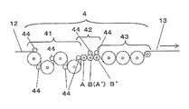
- FIG. 2 it is possible to improve the cooling capacity on the opposite surface by disposing a refrigerant nip roller 33 that allows the refrigerant to flow inside on the side opposite to the first cooling drum 31.
- the wet gel-like sheet 12 may be pressed against the drum 21 by using a close contact means such as a nip roller, a jet nozzle, a suction chamber, or electrostatic application so that the cooling efficiency is not lowered or meandering due to lubrication. .
- close contact means are preferable because the cooling efficiency of the gel-like sheet 12 is improved in addition to the improvement of traveling performance, and the above cooling rate and final cooling temperature setting are facilitated.
- the gel-like sheet 12 is pressed between the second cooling drum 32 and other transport rollers using a nip roller, thereby increasing the frictional force reduced on the mirror surface.
- the surface of the nip roller is a flexible rubber-like elastic body so that the gel-like sheet 12 can be uniformly pressed against uneven thickness of the gel-like sheet 12, deflection of the roller, and slight unevenness of the surface.
- Common vulcanized rubbers such as nitrile butyl rubber (NBR), chloroprene rubber (CR), ethylene propylene rubber (EPDM), and hyperon rubber (CSM) are preferred but not limited thereto.
- the gel-like sheet 12 and the conveying roller temperature are high, specifically, when the temperature is 80 ° C. or higher, the EPDM and CSM are particularly preferable.
- silicone rubber and fluororubber are suitable in addition to the vulcanized rubber. In this case, it is preferable to select a rubber that is less swelled by the diluent because the roller shape can be prevented from becoming distorted with time.
- the both ends of the uniaxially stretched sheet 13 are gripped by a conventionally used clip or the like.
- the sheet is stretched in the width direction of the sheet (a direction perpendicular to the conveying direction) while the sheet is conveyed in the traveling direction while being heated and kept warm in the oven 5.
- the sheet conveying direction stretching (hereinafter referred to as longitudinal stretching) step is composed of a roller having a temperature control mechanism such as a heater inside a conventional surface such as a metal and the like, similarly to the cooling drum, and the driving is the same. .
- a temperature control mechanism such as a heater inside a conventional surface such as a metal and the like
- the idler roller since the coefficient of friction between the wet film and the roller is small, it is preferable that the idler roller has a small bearing and inertia loss so that the rotational force is small, and it is also preferable not to provide more than necessary.
- the internal structure of the temperature raising roller group 41 and the stretching roller group 42 is also provided with a flow path so as to flow a heat medium such as steam or pressurized hot water inside the roller similarly to the first cooling drum 31 and heated.
- a heat medium such as steam or pressurized hot water inside the roller similarly to the first cooling drum 31 and heated.
- the roller is supported by a bearing so that it can be rotated, and in order to supply a heat medium inside, a rotatable joint (generally called a rotary joint) for supplying a heat medium that does not disturb the rotation of the roller is used as a shaft. It may be connected to the end and connected to the heat medium supply pipe.
- the stretching ratio varies depending on the thickness of the gel sheet, but the stretching in the sheet conveying direction is preferably performed at 5 to 12 times.
- the area magnification is preferably 30 times or more, more preferably 40 times or more, and further preferably 60 times or more. It is.
- the stretching temperature is preferably below the melting point of the polyolefin resin, and more preferably in the range of (polyolefin resin crystal dispersion temperature Tcd) to (polyolefin resin melting point).
- Tcd polyolefin resin crystal dispersion temperature
- the temperature is from 80 to 130 ° C, more preferably from 100 to 125 ° C. After stretching, cooling is performed below these temperatures.
- the uniaxially stretched sheet 13 or the biaxially stretched sheet 14 thus obtained is finely washed by removing and washing the diluent by a conventional technique, for example, the method described in International Publication No. 2008-016174.
- a porous plastic film 11 is obtained.
- the microporous plastic film 11 When the microporous plastic film 11 is obtained, it may be re-heated and re-stretched in the dry stretching step 7 after the washing step 6.
- the redrawing step 7 may be either a roller type or a tenter type, and physical properties can be adjusted and residual strain can be removed by performing a heat treatment in the same step. Further, depending on the application, the surface of the microporous plastic film 11 may be subjected to surface treatment such as corona discharge or functional coating such as heat-resistant particles.
- the diluent contained in the gel-like sheet 12 is bleed out by being cooled by the first cooling drums 31 and 32. Further, the diluent bleeds out even under the pressure due to the conveying tension here. For the same reason, after discharging from the base 23, the surfaces of the gel-like sheet 12 and the stretched films 13 and 14 are wet with the diluent until the diluent is removed and washed in the washing step 6.
- the gel-like sheet 12 is heated to the stretching temperature, for example, by the temperature raising roller group 41 in the longitudinal stretching step 4, and the bleeding out of the diluent is accelerated by the temperature rising.
- a large amount of bleed out occurs from the first cooling drum 31 to the upstream of the longitudinal stretching step 4, that is, from the heating roller group 41.
- a pan (not shown) may be installed to collect and discard or reuse the diluent.
- a gripping force (frictional force) is required between the roller and the gel-like sheet 12, and a high tension is generated by stretching particularly in the stretching portion. Therefore, in order to obtain a necessary stretching ratio, a high gripping force that is balanced with the stretching tension is required.
- the diluent bleed out as described above is interposed between the roller and the gel-like sheet 12 and becomes in a lubricated state, which causes a reduction in gripping force necessary for conveyance and stretching.
- the inventors of the present application have found that there is a correlation between the cooling rate by the first cooling drum 31 and the surface state of the gel-like sheet 12 that causes the reduction of the gripping force.
- the temperature of the first cooling drum 31 greatly affects the crystal structure of the gel sheet 12.
- the crystal structure becomes dense when the cooling rate is fast, and the crystal structure becomes large when it is slow. It was found that the faster the cooling rate and the denser the crystal structure, the easier it is to slip when the diluent is lubricated.
- the amount of diluent bleed out from the surface in contact with the first cooling drum 31 in the temperature rising portion of the longitudinal stretching step 4 from the cooling drum 31 was large.
- the gel sheet 12 is rapidly cooled by the first cooling drum 31, and preferably the surface of the gel sheet 12 opposite to the surface in contact with the first cooling drum 31 is also cooled by the air nozzle or the refrigerant nip roller 33 as described above. By doing so, the inner layer part of the gel-like sheet 12 in the thickness direction can be crystallized as uniformly as possible.
- the first cooling drum 31 since the first cooling drum 31 contacts the gel sheet 12 and directly transfers heat, the first cooling drum 31 has higher cooling efficiency than an air nozzle or an air chamber.
- the refrigerant nip roller as shown in FIG. 2 has the same heat transfer performance as the first cooling drum 31, the cooling efficiency is smaller than that of the first cooling drum 31 because it does not have a contact length.
- the cooling rate naturally increases on the side. Therefore, in the process of manufacturing the microporous plastic film, the surface that contacts the first cooling drum 31 has a higher cooling rate than the surface opposite to the surface that contacts the first cooling drum 31, and the crystal structure of the gel-like sheet 12 Becomes dense, and the bleed-out amount of the diluent also increases. Therefore, the surface of the gel-like sheet 12 in contact with the first cooling drum 31 has a small gripping force and frictional force with the roller, and slipping easily occurs.
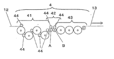
- the heating roller group 41 and the stretching roller group 42 are common in that the temperature of the gel-like sheet 12 is raised and heated and the roller rotation speed can be made variable. Since this is a roller for substantially stretching the sheet 12, it is a roller for providing a difference in peripheral speed for causing the gel-like sheet 12 to be permanently deformed in the traveling direction. More specifically, a roller that gives a circumferential speed difference of 3% or more with respect to an upstream roller is defined as a roller that substantially extends, that is, a stretching roller group 42.
- At least two stretching rollers (A) and (B) in the longitudinal stretching step 4 are provided.
- the upstream of the stretching roller group 42 in FIG. As B) the rollers (A) and the surface of the roller (B) are stretched in contact with the surface on the opposite side of the surface of the gel sheet 12 that is in contact with the first cooling drum.
- the rotational speed of A) and roller (B) is controlled.
- the temperature raising roller group 41 bears the stretching tension on the upstream side to some extent, but the gripping force of the roller (A) is increased, so that the stretching is further stabilized and the necessary stretching ratio is maintained. In addition, conveyance problems such as meandering can be avoided. Even when the stretching tension is balanced on the downstream side, the clip that grips the end of the uniaxially stretched sheet 13 in the lateral stretching step 5 is heavily burdened, but the gripping force of the roller (B) increases. Also, the downstream side is stretched without slipping, and problems such as meandering can be avoided.
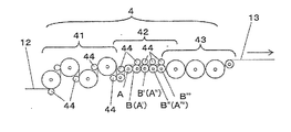
- the first cooling is performed between the roller (A) and the roller (B) in the drawing among the rollers that contact the surface opposite to the surface that contacts the first cooling drum 31 of the gel sheet 12 as shown in FIG.
- the roller (C) that contacts the surface that contacts the drum 31 is disposed, the roller (A) and the roller (B) may be substantially stretched, and the roller (C) is a roller so as not to contribute to stretching.
- the rotational speed of (C) must be controlled. Specifically, when stretching 5 times with respect to the roller (A), the rotation speed of the roller (B) is set to 5 times that of the roller (A).
- the gel-like sheet 12 between the roller (A) and the roller (B) is increased in speed while being stretched, that is, extending in the traveling direction.
- rate of a roller (C) be the middle of a roller (A) and a roller (B) so that the said roller (C) arrange
- a roller not to increase or decrease from the torque before stretching while monitoring the torque of the motor directly connected to the roller (C).
- the roller (C) does not give any torque to the stretched sheet, i.e., stretching force, so it does not contribute to stretching, and the roller (A) and the roller (B) substantially. Stretching can be performed.
- the torque before stretching refers to the torque when the roller is rotated without passing the sheet, or the torque when the non-stretched sheet is conveyed. This is mainly the rotational resistance of motor and roller bearings and rotary joints.
- the neck-in is reduced by the frictional resistance in the width direction by the roller (C) as compared with the arrangement as shown in FIG. Preferred above. Even if it is attempted to adjust the speed of the roller (C) so that the roller (C) does not contribute to stretching, it is difficult to completely adjust the roller (C), so the roller (C) slightly contributes to stretching. May end up.
- rollers (C) do not contribute to the stretching, and the rollers are rotated by setting the speed conditions so that the stretching is performed only by the rollers (A) and (B). , “Elongation is substantially performed by the roller (A) and the roller (B)”.
- the gel sheet 12 is pressed by the nip roller between the temperature raising roller group 41 and the stretching roller group 42 to increase the frictional force reduced by the lubricant lubrication. it can.
- the nip roller is used together to increase the frictional force with the stretching roller and to increase the gripping force.
- the gripping force on the upstream side of the stretching tension is shared little by little, and the base 23 and the first cooling drum 31 are in a molten state. It is possible to prevent problems such as thickness unevenness due to stretching tension on the gel sheet 12.
- the gel-like sheet 12 is introduced into the temperature rising roller group 41 and the drawing roller group 42 by the nip roller as shown in FIGS.
- the thickness unevenness quality and appearance quality in stretching can be improved, and slipping and meandering can be prevented.
- a diluent or air accompanies the sheet 12 with a certain thickness between the stretching roller 42 or the temperature raising roller 41 and then the nip roller. This is because a bank is formed to be nipped by 44.
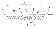
- the nip rollers By arranging the nip rollers substantially tangentially, the thickness of the diluent and air is suppressed by the nip rollers 44 before the sheet is brought into contact with the stretching roller group 42 and the temperature raising roller group 41, so that the bank is in a gel form A stretched sheet with higher quality cannot be obtained between the sheet 12 and the roller.
- the nip rollers In the case where it is not desired to stretch the gel sheet 12 while making contact with the stretching roller, if two nip rollers are arranged on the stretching roller (A) as shown in FIG. good.
- tangentially nipping means that the nip roller is nipped at a position where the gel-like sheet 12 starts to contact the heating roller 41 or the stretching roller 42. When the nip roller is nipped at this position, the gel-like sheet 12 becomes like a tangent line of the nip roller. Further, “substantially tangentially nip” means that it is slightly shifted from the position where contact begins, as long as the purpose of niping so as not to be banked is achieved, even if it is not the position where contact begins strictly. Even so, it means the original “tangentially nip”.
- the surface of the nip roller is also made of a flexible rubber-like elastic body so that the gel-like sheet 12 can be uniformly pressed against uneven thickness of the gel-like sheet 12, deflection of the roller, and slight irregularities on the surface.
- the longitudinal stretching process involves conveyance at a temperature equal to or higher than the thermal diffusion temperature
- rubbers having high heat resistance such as EPDM and hyperon rubber are more preferable, and silicone rubber and fluorine rubber are more preferable.
- the roller (C) that does not contribute to stretching is arranged between the rollers (A) and (B) as shown in FIG. 3, and the distance that the gel sheet 12 slides in the air is shortened. It is preferable because the neck-in can be reduced by the gripping force in the width direction with the roller, but it is preferable that the roller (A) and the roller (B) are adjacent to each other as shown in FIGS. ), It is not necessary to control the speed of the roller unrelated to stretching, and the apparatus is simplified and the cost can be reduced.
- rollers such that there are a plurality of combinations of the roller (A) and the roller (B) in the longitudinal stretching step.
- the most upstream roller in the stretching roller group 42 is (A) and the next roller is (B), and stretching is performed with a speed difference in this section.
- the roller (B) described above is regarded as a roller (A)
- the next roller is regarded as a roller (B)
- the second stage of stretching is performed as a roller (A ′) and a roller (B ′), respectively. Control the speed to do.
- the sheet is cooled once by the cooling roller group 43 and conveyed to the tenter oven 5, whereby the process paper passing work of the uniaxially stretched sheet 13 is performed.
- a microporous plastic film with higher orientation and strength can be obtained by the effect of solidifying the crystal structure formed by longitudinal stretching.
- cooling is preferably performed immediately after stretching, and when the combination of the rollers (A) and (B) is at least one set in the longitudinal stretching step, the most downstream roller (B) is a cooling roller.
- the effect of increasing the strength can be maximized.
- a polyethylene (PE) composition comprising 40% by mass of ultrahigh molecular weight polyethylene having a weight average molecular weight (Mw) of 2.5 ⁇ 10 6 and 60% by mass of high density polyethylene (HDPE) having an Mw of 2.8 ⁇ 10 5
- Mw weight average molecular weight
- HDPE high density polyethylene
- the obtained mixture was charged into the twin-screw extruder 21 at a flow rate of 97 kg / hr using a film forming method as shown in FIG. 1, and liquid paraffin as a diluent was charged at a flow rate of 291 kg / hr, and 210 ° C. Mix at the temperature of
- the obtained polyethylene solution was supplied to the base 23 while being measured with a gear pump, and the polyethylene solution having a temperature of 210 ° C. was discharged onto the first cooling drum 31 whose temperature was controlled to 35 ° C. to form the gel sheet 12. .
- the first cooling drum 31 was rotationally driven at a speed of 10 m / min.
- the thickness of the obtained gel-like sheet 12 was 100 mm square before being introduced into the longitudinal stretching step 4 and measured with a contact-type thickness meter. As a result, the average of 10 times was 1.5 mm. A bleed-out diluent adheres to the surface, and the thickness measurement has a variation of ⁇ 0.1 mm at the maximum.
- the obtained gel-like sheet 12 was heated with the first metal water-feeding roller of the heating roller group 41 and the drawing roller group 42 so that the temperature of the sheet surface became 110 ° C.
- the motor rotation number directly connected to the rollers is increased so as to become faster downstream with a speed difference of 1% according to the thermal expansion of the sheet. Controlled.
- the stretching roller group 42 is composed of two rollers as shown in FIG. 1, and a nip roller 44 whose surface is covered with rubber is arranged on each roller, and longitudinal stretching is performed by a speed difference between the rollers.
- the stretched film 13 was cooled by four rollers of the cooling unit 43 including the last roller of the stretching roller group 42, and the water flow roller temperature was adjusted so that the sheet temperature became 50 ° C.
- the speed difference between the last stretching roller, the cooling roller group 43, and the clips in the transverse stretching process 5 was set to 0 and the same speed.
- the nip roller disposed on the roller (A) is not substantially tangential, and the gel-like sheet 12 and the roller (A) start contact with each other, and the wrapping angle of 45 ° is reached.
- the nip roller 44 was nipped on the gel sheet 12.
- the nip roller 44 disposed on the roller (B) nipped the gel sheet 12 in a tangential manner.
- the surfaces of all the rollers in the longitudinal stretching step 4 were coated with hard chrome plating on the surface of a steel roller and had a surface roughness of 0.4 ⁇ m at the maximum height.
- the upstream roller (A) that contacts the surface opposite to the surface that contacts the first cooling drum 31 of the gel sheet 12, and the surface that contacts the surface opposite to the surface that contacts the drum 31.
- Methylene chloride obtained by holding both ends of the obtained stretched film 13 with a clip, transversely stretching in an oven 5 at a magnification of 6 times, at a temperature of 115 ° C., and cooled to 30 ° C., and adjusting the temperature to 25 ° C.
- liquid paraffin was removed.
- the washed film is dried in a drying furnace adjusted to 60 ° C., and is re-stretched in the re-stretching step 7 so that the area magnification is 1.2 times in the longitudinal direction ⁇ lateral direction. Heat treatment was performed for 2 seconds to obtain a microporous plastic film 11 having a thickness of 16 ⁇ m and a width of 2000 mm.
- the amount of diluent that bleeds out from the front and back surfaces of the cast gel-like sheet 12 formed into a film with the above composition and extrusion amount was measured.
- a scraper with a sharp tip on the surface of the gel sheet 12 is brought into contact with the sheet 12 with a pressing force of 20 N / m on each side of the surface.
- the diluent was scraped off, the weight of the diluent dripping from the side surface of the gel sheet 12 was measured for 1 minute, and the amount of bleed out per unit time was measured.
- the measurement method of the friction coefficient was a conventional method shown in Formula 2 of FIG. 5 of International Publication 2012/133097 Pamphlet.
- a sheet of paper cut to a width of 100 mm is wound around a longitudinal stretching roller (surface is hard chrome plating with a maximum height of 0.4 ⁇ m as described above) at a normal temperature of 25 ° C. at a contact angle of 90 ° and a weight of 2 kg.
- the measurement was carried out by hanging. In this case, it was carried out while confirming that the stopped roller did not rotate by measurement due to the resistance of the stopped motor.
- Two types of friction coefficients were compared, one using a Kimberley Clark paper waste “Kimwipe” and the one where the diluent was wiped visually until there was no liquid pool, and the other was wiped while sampling.
- Example 2 In the configuration as shown in FIG. 3, the stretching roller group 42 in the longitudinal stretching process 4 is composed of three rollers, and the speed is adjusted so that the motor rotation torque of the stretching roller (C) does not change from the torque during no-load operation.
- a microporous plastic film was produced under the same apparatus and conditions as in Example 1 except that the film was substantially stretched by the roller (A) and the roller (B).
- Example 3 In the configuration as shown in FIG. 4, the nip roller 44 is disposed substantially tangentially for all of the temperature raising roller group 41 and the stretching roller group 42 in the longitudinal stretching step 4, and then the stretching roller (A) and the roller (B A microporous plastic film was produced using the same apparatus and conditions as in Example 1 except that the film was stretched between the two.
- Example 4 In the configuration as shown in FIG. 5, three rollers are arranged as the stretching roller group 42, and the first stage stretching is performed between the roller (A) and the roller (B), and the second roller (B) is disposed.
- the second stage of stretching was carried out using the roller (A ′) and the third roller as the roller (B ′).
- the first stage draw ratio is 2 times
- the second stage draw ratio is 4.33 times
- the same magnification as in Example 1 was used. Other conditions were the same as in Example 1.
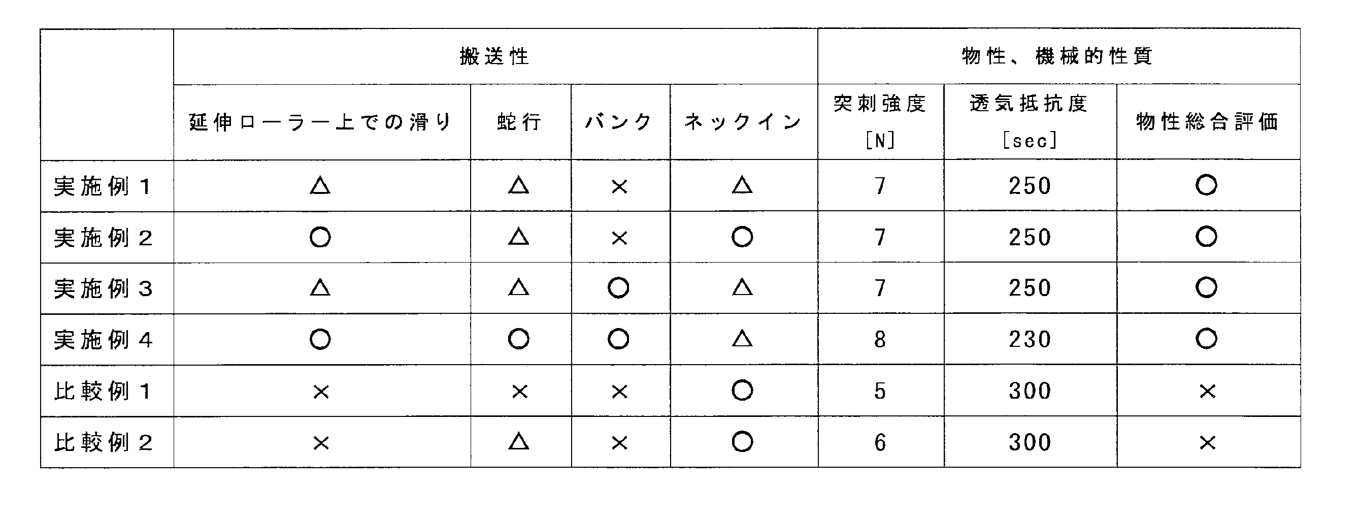
- the produced microporous plastic film was evaluated according to the following criteria, and the results are shown in Table 2.
- [Meandering amount in the longitudinal stretching process] The amount of meandering in the longitudinal stretching step 4 was evaluated according to the following criteria.
- X impossible: The amount of meandering is 10 mm or more.
- ⁇ possible: The meandering amount is 5 mm or more and less than 10 mm.
- ⁇ Good: The amount of meandering is less than 5 mm.
- Example 3 and Example 4 the gel-like sheet 12 starts to contact the stretching roller, so the sheet is substantially tangentially niped.
- An air bank could not be produced, and a microporous film excellent in appearance and thickness unevenness could be produced.
- Example 2 the amount of neck-in could be suppressed by the stretching roller (C), but Examples 1 and 3 and 4 were roller (A) and roller (B), or roller (A ′) and roller. Since (B ′) is an adjacent roller, an operation of adjusting the speed while watching the torque of the roller (C) was unnecessary.
- a microporous plastic film excellent in strength and physical properties while maintaining running stability under the necessary stretching conditions when performing stretching necessary to obtain various properties of the microporous film. Can be obtained.
- the present invention can be used for microporous plastic films used for separators of electrochemical reactors such as secondary batteries, fuel cells, capacitors, etc., and also applied to functional webs such as filtration membranes, printed membranes and various clothing materials.
- functional webs such as filtration membranes, printed membranes and various clothing materials.
- the application range is not limited to these.
- Microporous plastic film 12 Gel-like sheet (film) 13 Uniaxially stretched sheet (film) 14 Biaxially stretched sheet (film) 15 Microporous Plastic Film Roll 21 Extruder 22 Gear Pump 23 Base 31 First Cooling Drum 32 Second Cooling Drum 33 Refrigerant Nip Roller 4 Longitudinal Stretching Step 41 Heating Roller Group 42 Stretching Roller Group 43 Cooling Roller Group 44 Nip Roller 5 Horizontal Stretching process 6 Cleaning / drying process 61 Cleaning solvent 7 Re-stretching heat treatment process 8 Winding process A Upstream stretching roller in contact with the surface of the sheet opposite to the first cooling drum B Contact with the first cooling drum of the sheet Downstream stretching roller in contact with the surface opposite to the finished surface C Roller auxiliary roller that conveys the sheet between rollers (A) and (B)
Abstract
Description
質量平均分子量(Mw)が2.5×10⁶の超高分子量ポリエチレンを40質量%、Mwが2.8×10⁵の高密度ポリエチレン(HDPE)60質量%とからなるポリエチレン(PE)組成物100質量部に、テトラキス[メチレン-3-(3,5-ジターシャリーブチル-4-ヒドロキシフェニル)-プロピオネート]メタン0.375質量部をドライブレンドし、混合物を得た。 [Example 1]
A polyethylene (PE) composition comprising 40% by mass of ultrahigh molecular weight polyethylene having a weight average molecular weight (Mw) of 2.5 × 10 6 and 60% by mass of high density polyethylene (HDPE) having an Mw of 2.8 × 10 5 To 100 parts by mass, 0.375 parts by mass of tetrakis [methylene-3- (3,5-ditertiarybutyl-4-hydroxyphenyl) -propionate] methane was dry blended to obtain a mixture.
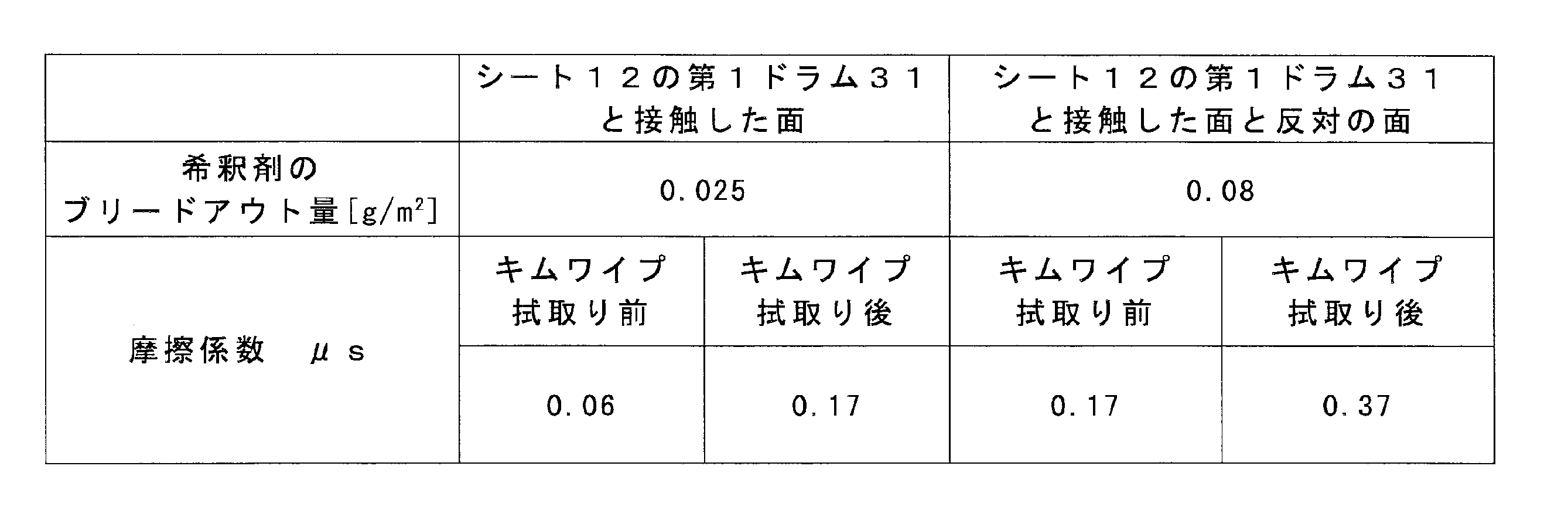
図3のような構成で、縦延伸工程4の延伸ローラー群42を3本のローラーから構成し、延伸ローラー(C)のモーター回転トルクが無負荷運転時のトルクと変化しないよう速度を調整し、実質的にローラー(A)とローラー(B)で延伸を行った他は、実施例1と同様の装置、条件で微多孔プラスチックフィルムを製造した。 [Example 2]
In the configuration as shown in FIG. 3, the stretching
図4のような構成で、縦延伸工程4の昇温ローラー群41および延伸ローラー群42の全てについて実質的に接線状にニップローラー44を配置した上で、延伸ローラー(A)とローラー(B)との間で延伸を行った他は、実施例1と同様の装置、条件で微多孔プラスチックフィルムを製造した。 [Example 3]
In the configuration as shown in FIG. 4, the
図5のような構成で、延伸ローラー群42として3本のローラーを配置し、ローラー(A)とローラー(B)との間で1段目の延伸を、前記2本目のローラー(B)をローラー(A’)とし、3本目のローラーをローラー(B’)として、2段目の延伸を実施した。前記1段目の延伸倍率を2倍とし、2段目の延伸倍率を4.33倍とし、1本目から3本目の総延伸倍率を2×4.33=8.66倍とすることで実施例1と同じ倍率とした。その他の条件は、実施例1と同じとした。 [Example 4]
In the configuration as shown in FIG. 5, three rollers are arranged as the stretching
図7のような構成で、延伸ローラー群42として2本のローラーを配置し、ローラー(A)とローラー(D)との間で延伸を行った。その他の条件は、実施例1と同じとした。 [Comparative Example 1]
In the configuration shown in FIG. 7, two rollers were arranged as the stretching
図8のような構成で、延伸ローラー群42として5本のローラーを配置し、ローラー(A)とローラー(D)との間で延伸を行った。その他の条件は、実施例1と同じとした。 [Comparative Example 2]
In the configuration as shown in FIG. 8, five rollers were arranged as the stretching
シートおよびローラーの速度は、非接触式ドップラー速度計(アクト電子株式会社製、モデル1522)を用いて、設置精度込みで1%の精度で計測した。
×(不可):ローラーとシートの速度差が、ローラー回転速度に対して10%以上。
△(可):ローラーとシートの速度差が、ローラー回転速度に対して5%以上10%未満。
○(良好):ローラーとシートの速度差が、ローラー回転速度に対して5%未満。 [Sliding on stretching roller]
The sheet and roller speeds were measured with a non-contact Doppler speedometer (Model 1522, manufactured by Act Electronics Co., Ltd.) with an accuracy of 1% including the installation accuracy.
X (impossible): The speed difference between the roller and the sheet is 10% or more with respect to the roller rotation speed.
Δ (possible): The speed difference between the roller and the sheet is 5% or more and less than 10% with respect to the roller rotation speed.
○ (Good): The speed difference between the roller and the sheet is less than 5% of the roller rotation speed.
縦延伸工程4における蛇行量を以下の基準で評価した。
×(不可):蛇行量が10mm以上。
△(可):蛇行量が5mm以上10mm未満。
○(良好):蛇行量が5mm未満。 [Meandering amount in the longitudinal stretching process]
The amount of meandering in the
X (impossible): The amount of meandering is 10 mm or more.
Δ (possible): The meandering amount is 5 mm or more and less than 10 mm.
○ (Good): The amount of meandering is less than 5 mm.
縦延伸工程4におけるバンクを以下の基準で評価した。
×(不可):縦延伸工程4のローラー上で空気溜まりが観察され、微多孔プラスチックフィルムの厚み斑として、厚みの大きい部位と小さい部位の差が、平均厚みに対して5%を越えるもの。
△(可):縦延伸工程4のローラー上で空気溜まりが観察されるが、微多孔プラスチックフィルムの厚み斑として、厚みの大きい部位と小さい部位の差が、平均厚みに対して5%を越えないもの。
○(良好):縦延伸工程4のローラー上で空気溜まりが観察されないもの。 [bank]
The banks in the
X (impossible): Air accumulation is observed on the roller in the
Δ (possible): Although air accumulation is observed on the roller in the
○ (Good): No air accumulation is observed on the roller in the
縦延伸工程4におけるネックインを以下の基準で評価した。
×(不可):縦延伸工程4に入るゲル状シート12の幅と、縦延伸工程4から横延伸工程5との間の一軸延伸シート13の幅の差が150mmを超える。
△(可):縦延伸工程4に入るゲル状シート12の幅と、縦延伸工程4から横延伸工程5との間の一軸延伸シート13の幅の差が100mm以上、150mm未満。
○(良好):縦延伸工程4に入るゲル状シート12の幅と、縦延伸工程4から横延伸工程5との間の一軸延伸シート13の幅の差が100mm未満。 [Neck-in]
The neck-in in the
X (impossible): The difference between the width of the gel-
Δ (possible): The difference between the width of the gel-
○ (Good): The difference between the width of the gel-
透気抵抗度は、王研式透気抵抗度計(旭精工株式会社製、EGO-1T)を使用して、JIS P8117に準拠して測定した。突刺強度は、先端が球面(曲率半径R:0.5mm)の直径1mmの針で、膜厚T1(μm)の微多孔膜を2mm/秒の速度で突刺したときの最大荷重を測定した。最大荷重の測定値Laを、式:Lb=(La×16)/T1により、膜厚を16μmとしたときの最大荷重Lbに換算し、突刺強度(N/16μm)とした。
○(可):透気抵抗度が250sec±20sec及び突刺強度6N以上。
×(不可):上記範囲外。 [Physical properties and mechanical properties of microporous plastic film]
The air resistance was measured according to JIS P8117 using an Oken type air resistance meter (AGO Seiko Co., Ltd., EGO-1T). For the puncture strength, the maximum load was measured when a microporous film having a film thickness T1 (μm) was pierced at a speed of 2 mm / sec with a needle having a spherical surface (curvature radius R: 0.5 mm) and a diameter of 1 mm. The measured value La of the maximum load was converted into the maximum load Lb when the film thickness was 16 μm by the formula: Lb = (La × 16) / T1, and the puncture strength (N / 16 μm) was obtained.
○ (possible): Air permeability resistance is 250 sec ± 20 sec and puncture strength is 6N or more.
X (impossible): outside the above range.
12 ゲル状シート(フィルム)
13 一軸延伸シート(フィルム)
14 二軸延伸シート(フィルム)
15 微多孔プラスチックフィルムロール
21 押出機
22 ギアポンプ
23 口金
31 第1冷却ドラム
32 第2冷却ドラム
33 通冷媒ニップローラー
4 縦延伸工程
41 昇温ローラー群
42 延伸ローラー群
43 冷却ローラー群
44 ニップローラー
5 横延伸工程
6 洗浄・乾燥工程
61 洗浄溶剤
7 再延伸熱処理工程
8 巻取工程
A シートの第1冷却ドラムと接触した面とは反対面と接触する上流側延伸ローラー
B シートの第1冷却ドラムと接触した面とは反対面と接触する下流側延伸ローラー
C ローラー(A)と(B)の間でシートを搬送する延伸部補助ローラー
11
13 Uniaxially stretched sheet (film)
14 Biaxially stretched sheet (film)
15 Microporous
Claims (8)
- 希釈剤とポリオレフィン樹脂とを押出機にて混練し、前記希釈剤が混練されたポリオレフィン樹脂を口金からシート状に吐出し、前記口金から吐出されたシートを1つまたは複数の冷却ドラム上で冷却して固化した後、固化した前記シートを再び加熱して、複数のローラーによりシートの搬送方向に延伸し、前記シートの搬送方向に延伸した前記シートを冷却した後に前記シート両端をクリップにて把持してテンターに導入し、その後前記希釈剤を洗浄することで1軸または2軸延伸微多孔プラスチックフィルムを得る製造方法において、
前記複数のローラーのうちの少なくとも2本以上をモーターにより駆動し、
前記冷却ドラムのうち、前記口金から吐出された前記シートが最初に接触する前記冷却ドラムを第1冷却ドラムとしたとき、前記モーターにより駆動される前記ローラーのうちの少なくとも2本のローラー(A)およびローラー(B)の表面を、前記シートの前記第1冷却ドラムと接触した面とは反対側の面に接触させ、
前記ローラー(A)および前記ローラー(B)の回転速度を、実質的にこれら2本のローラーの間で前記シートを延伸できるように制御する、微多孔プラスチックフィルムの製造方法。 The diluent and polyolefin resin are kneaded with an extruder, the polyolefin resin kneaded with the diluent is discharged from the die into a sheet shape, and the sheet discharged from the die is cooled on one or more cooling drums. Then, the solidified sheet is heated again, stretched in the sheet conveying direction by a plurality of rollers, and after cooling the sheet stretched in the sheet conveying direction, the both ends of the sheet are held by clips In the production method of obtaining a uniaxially or biaxially stretched microporous plastic film by introducing it into a tenter and then washing the diluent,
Driving at least two of the plurality of rollers by a motor;
Among the cooling drums, when the first cooling drum is the cooling drum that is first contacted by the sheet discharged from the base, at least two rollers (A) among the rollers driven by the motor And the surface of the roller (B) is brought into contact with the surface of the sheet opposite to the surface in contact with the first cooling drum,
The manufacturing method of a microporous plastic film which controls so that the rotation speed of the said roller (A) and the said roller (B) can extend | stretch the said sheet | seat between these two rollers substantially. - 前記ローラー(A)および前記ローラー(B)の少なくとも一方で、前記シートが接触を開始する点で、ニップローラーによりシートを実質的に接線状にニップする、請求項1の微多孔プラスチックフィルムの製造方法。 The production of the microporous plastic film according to claim 1, wherein at least one of the roller (A) and the roller (B) nips the sheet substantially tangentially by a nip roller at a point where the sheet starts to contact. Method.
- 前記ローラー(A)と前記ローラー(B)とが互いに隣り合う、請求項1または2に記載の微多孔プラスチックフィルムの製造方法。 The method for producing a microporous plastic film according to claim 1 or 2, wherein the roller (A) and the roller (B) are adjacent to each other.
- 前記ローラー(A)と前記ローラー(B)の組み合わせが、縦延伸工程内で複数組ある、請求項1~3のいずれか一項に記載の微多孔プラスチックフィルムの製造方法。 The method for producing a microporous plastic film according to any one of claims 1 to 3, wherein there are a plurality of combinations of the roller (A) and the roller (B) in the longitudinal stretching step.
- 前記ローラー(A)と前記ローラー(B)の組み合わせが1組以上あり、これらローラーのうちの最下流のローラーが冷却ローラーである、請求項1~4のいずれか一項に記載の微多孔プラスチックフィルムの製造方法。 The microporous plastic according to any one of claims 1 to 4, wherein there is one or more combinations of the roller (A) and the roller (B), and the most downstream of these rollers is a cooling roller. A method for producing a film.
- 請求項1~5のいずれか一項に記載の微多孔プラスチックフィルムの製造方法で製造した微多孔プラスチックフィルム。 A microporous plastic film produced by the method for producing a microporous plastic film according to any one of claims 1 to 5.
- 請求項6に記載の微多孔プラスチックフィルムを用いた電池用セパレータ。 Battery separator using the microporous plastic film according to claim 6.
- 請求項7に記載の電池用セパレータを用いた電池。
A battery using the battery separator according to claim 7.
Priority Applications (5)
| Application Number | Priority Date | Filing Date | Title |
|---|---|---|---|
| KR1020177022883A KR102357540B1 (en) | 2015-02-20 | 2016-01-22 | Method for manufacturing microporous plastic film |
| CN201680011154.8A CN107249854A (en) | 2015-02-20 | 2016-01-22 | The manufacture method of micro- porous plastic film |
| US15/551,309 US20180036932A1 (en) | 2015-02-20 | 2016-01-22 | Method of producing microporous plastic film |
| JP2017500560A JP6836743B2 (en) | 2015-02-20 | 2016-01-22 | Manufacturing method of microporous plastic film |
| EP16752195.4A EP3260271B1 (en) | 2015-02-20 | 2016-01-22 | Method for producing microporous plastic film |
Applications Claiming Priority (2)
| Application Number | Priority Date | Filing Date | Title |
|---|---|---|---|
| JP2015-031388 | 2015-02-20 | ||
| JP2015031388 | 2015-02-20 |
Publications (1)
| Publication Number | Publication Date |
|---|---|
| WO2016132806A1 true WO2016132806A1 (en) | 2016-08-25 |
Family
ID=56692098
Family Applications (1)
| Application Number | Title | Priority Date | Filing Date |
|---|---|---|---|
| PCT/JP2016/051776 WO2016132806A1 (en) | 2015-02-20 | 2016-01-22 | Method for producing microporous plastic film |
Country Status (7)
| Country | Link |
|---|---|
| US (1) | US20180036932A1 (en) |
| EP (1) | EP3260271B1 (en) |
| JP (1) | JP6836743B2 (en) |
| KR (1) | KR102357540B1 (en) |
| CN (1) | CN107249854A (en) |
| HU (1) | HUE051622T2 (en) |
| WO (1) | WO2016132806A1 (en) |
Cited By (2)
| Publication number | Priority date | Publication date | Assignee | Title |
|---|---|---|---|---|
| US11139499B2 (en) | 2018-06-01 | 2021-10-05 | Hyundai Motor Company | Manufacturing apparatus of membrane electrode assembly with excellent mass transfer characteristics and durability, and manufacturing method using the same |
| CN113580522A (en) * | 2021-08-05 | 2021-11-02 | 揭西鑫昌顺电子科技有限公司 | Novel tensile mode TPU membrane manufacture equipment |
Families Citing this family (2)
| Publication number | Priority date | Publication date | Assignee | Title |
|---|---|---|---|---|
| CN111933877B (en) * | 2020-06-30 | 2021-12-21 | 江苏厚生新能源科技有限公司 | High-roughness base film for coating and preparation method thereof |
| CN111942015B (en) * | 2020-08-05 | 2022-04-01 | 上海弗列加滤清器有限公司 | Device for increasing surface tension of product |
Citations (7)
| Publication number | Priority date | Publication date | Assignee | Title |
|---|---|---|---|---|
| JPS5022069A (en) * | 1973-05-30 | 1975-03-08 | ||
| JPS5165178A (en) * | 1974-12-04 | 1976-06-05 | Dainippon Printing Co Ltd | |
| JPH0257316A (en) * | 1988-05-04 | 1990-02-27 | Skc Ltd | Method and device for manufacturing poly-epsilon-capron amide film |
| JP2009249480A (en) * | 2008-04-04 | 2009-10-29 | Toshiba Mach Co Ltd | Method of manufacturing porous film and successive biaxial stretching apparatus for manufacturing porous film |
| WO2010018749A1 (en) * | 2008-08-15 | 2010-02-18 | Tonen Chemical Corporation | Chill roll system and process for producing a microporous membrane |
| JP2010160483A (en) * | 2008-12-10 | 2010-07-22 | Fujifilm Corp | Film, method for manufacturing film, polarizing plate, and liquid crystal display device |
| WO2010095518A1 (en) * | 2009-02-23 | 2010-08-26 | コニカミノルタオプト株式会社 | Optical film manufacturing method, optical film, polarizing plate, and liquid crystal display device |
Family Cites Families (6)
| Publication number | Priority date | Publication date | Assignee | Title |
|---|---|---|---|---|
| DE68925429T3 (en) * | 1988-06-23 | 1999-12-02 | Toray Industries | METHOD FOR PRODUCING A POLYESTER FILM |
| JP2010540691A (en) * | 2007-09-20 | 2010-12-24 | 東燃化学株式会社 | Microporous membranes and methods of making and using such membranes |
| KR101336593B1 (en) * | 2010-04-20 | 2013-12-05 | 에스케이이노베이션 주식회사 | Method with good productivity for preparing microporous polyolefin film with various properties |
| CN103459478B (en) | 2011-05-02 | 2015-06-10 | 野方铁郎 | Manufacturing device and manufacturing method of polyolefin microporous film |
| WO2013100062A1 (en) * | 2011-12-27 | 2013-07-04 | 東レ株式会社 | Manufacturing device and manufacturing method for microporous plastic film roll |
| CN104024316B (en) * | 2011-12-28 | 2016-01-20 | 东丽电池隔膜株式会社 | Polyolefin micro porous polyolefin membrane and manufacture method thereof |
-
2016
- 2016-01-22 KR KR1020177022883A patent/KR102357540B1/en active IP Right Grant
- 2016-01-22 CN CN201680011154.8A patent/CN107249854A/en active Pending
- 2016-01-22 HU HUE16752195A patent/HUE051622T2/en unknown
- 2016-01-22 US US15/551,309 patent/US20180036932A1/en not_active Abandoned
- 2016-01-22 WO PCT/JP2016/051776 patent/WO2016132806A1/en active Application Filing
- 2016-01-22 EP EP16752195.4A patent/EP3260271B1/en active Active
- 2016-01-22 JP JP2017500560A patent/JP6836743B2/en active Active
Patent Citations (7)
| Publication number | Priority date | Publication date | Assignee | Title |
|---|---|---|---|---|
| JPS5022069A (en) * | 1973-05-30 | 1975-03-08 | ||
| JPS5165178A (en) * | 1974-12-04 | 1976-06-05 | Dainippon Printing Co Ltd | |
| JPH0257316A (en) * | 1988-05-04 | 1990-02-27 | Skc Ltd | Method and device for manufacturing poly-epsilon-capron amide film |
| JP2009249480A (en) * | 2008-04-04 | 2009-10-29 | Toshiba Mach Co Ltd | Method of manufacturing porous film and successive biaxial stretching apparatus for manufacturing porous film |
| WO2010018749A1 (en) * | 2008-08-15 | 2010-02-18 | Tonen Chemical Corporation | Chill roll system and process for producing a microporous membrane |
| JP2010160483A (en) * | 2008-12-10 | 2010-07-22 | Fujifilm Corp | Film, method for manufacturing film, polarizing plate, and liquid crystal display device |
| WO2010095518A1 (en) * | 2009-02-23 | 2010-08-26 | コニカミノルタオプト株式会社 | Optical film manufacturing method, optical film, polarizing plate, and liquid crystal display device |
Non-Patent Citations (1)
| Title |
|---|
| See also references of EP3260271A4 * |
Cited By (2)
| Publication number | Priority date | Publication date | Assignee | Title |
|---|---|---|---|---|
| US11139499B2 (en) | 2018-06-01 | 2021-10-05 | Hyundai Motor Company | Manufacturing apparatus of membrane electrode assembly with excellent mass transfer characteristics and durability, and manufacturing method using the same |
| CN113580522A (en) * | 2021-08-05 | 2021-11-02 | 揭西鑫昌顺电子科技有限公司 | Novel tensile mode TPU membrane manufacture equipment |
Also Published As
| Publication number | Publication date |
|---|---|
| JP6836743B2 (en) | 2021-03-03 |
| EP3260271A4 (en) | 2018-11-07 |
| EP3260271A1 (en) | 2017-12-27 |
| US20180036932A1 (en) | 2018-02-08 |
| EP3260271B1 (en) | 2020-09-02 |
| CN107249854A (en) | 2017-10-13 |
| JPWO2016132806A1 (en) | 2017-11-30 |
| KR20170118739A (en) | 2017-10-25 |
| HUE051622T2 (en) | 2021-03-01 |
| KR102357540B1 (en) | 2022-02-03 |
Similar Documents
| Publication | Publication Date | Title |
|---|---|---|
| JP6773022B2 (en) | Manufacturing method of microporous plastic film | |
| JP6555252B2 (en) | Method for producing microporous plastic film | |
| JP6773023B2 (en) | Manufacturing method of microporous plastic film | |
| WO2016132810A1 (en) | Method for producing microporous plastic film | |
| WO2016132806A1 (en) | Method for producing microporous plastic film | |
| WO2016132809A1 (en) | Method for producing microporous plastic film | |
| CN109071864B (en) | Polyolefin microporous membrane, battery separator, and method for producing same |
Legal Events
| Date | Code | Title | Description |
|---|---|---|---|
| 121 | Ep: the epo has been informed by wipo that ep was designated in this application |
Ref document number: 16752195 Country of ref document: EP Kind code of ref document: A1 |
|
| ENP | Entry into the national phase |
Ref document number: 2017500560 Country of ref document: JP Kind code of ref document: A |
|
| WWE | Wipo information: entry into national phase |
Ref document number: 15551309 Country of ref document: US |
|
| ENP | Entry into the national phase |
Ref document number: 20177022883 Country of ref document: KR Kind code of ref document: A |
|
| NENP | Non-entry into the national phase |
Ref country code: DE |
|
| REEP | Request for entry into the european phase |
Ref document number: 2016752195 Country of ref document: EP |