WO2016132584A1 - 直線配置型の接眼映像表示装置 - Google Patents
直線配置型の接眼映像表示装置 Download PDFInfo
- Publication number
- WO2016132584A1 WO2016132584A1 PCT/JP2015/077270 JP2015077270W WO2016132584A1 WO 2016132584 A1 WO2016132584 A1 WO 2016132584A1 JP 2015077270 W JP2015077270 W JP 2015077270W WO 2016132584 A1 WO2016132584 A1 WO 2016132584A1
- Authority
- WO
- WIPO (PCT)
- Prior art keywords
- light
- polarization
- eyepiece
- polarization separation
- separation element
- Prior art date
- Legal status (The legal status is an assumption and is not a legal conclusion. Google has not performed a legal analysis and makes no representation as to the accuracy of the status listed.)
- Ceased
Links
Images

Classifications
-
- G—PHYSICS
- G02—OPTICS
- G02B—OPTICAL ELEMENTS, SYSTEMS OR APPARATUS
- G02B25/00—Eyepieces; Magnifying glasses
- G02B25/001—Eyepieces
-
- G—PHYSICS
- G02—OPTICS
- G02B—OPTICAL ELEMENTS, SYSTEMS OR APPARATUS
- G02B27/00—Optical systems or apparatus not provided for by any of the groups G02B1/00 - G02B26/00, G02B30/00
- G02B27/01—Head-up displays
- G02B27/017—Head mounted
- G02B27/0172—Head mounted characterised by optical features
-
- G—PHYSICS
- G02—OPTICS
- G02B—OPTICAL ELEMENTS, SYSTEMS OR APPARATUS
- G02B27/00—Optical systems or apparatus not provided for by any of the groups G02B1/00 - G02B26/00, G02B30/00
- G02B27/01—Head-up displays
- G02B27/017—Head mounted
- G02B27/0176—Head mounted characterised by mechanical features
-
- G—PHYSICS
- G02—OPTICS
- G02B—OPTICAL ELEMENTS, SYSTEMS OR APPARATUS
- G02B27/00—Optical systems or apparatus not provided for by any of the groups G02B1/00 - G02B26/00, G02B30/00
- G02B27/28—Optical systems or apparatus not provided for by any of the groups G02B1/00 - G02B26/00, G02B30/00 for polarising
- G02B27/283—Optical systems or apparatus not provided for by any of the groups G02B1/00 - G02B26/00, G02B30/00 for polarising used for beam splitting or combining
-
- G—PHYSICS
- G02—OPTICS
- G02B—OPTICAL ELEMENTS, SYSTEMS OR APPARATUS
- G02B27/00—Optical systems or apparatus not provided for by any of the groups G02B1/00 - G02B26/00, G02B30/00
- G02B27/01—Head-up displays
- G02B27/0101—Head-up displays characterised by optical features
- G02B2027/0145—Head-up displays characterised by optical features creating an intermediate image
-
- G—PHYSICS
- G02—OPTICS
- G02B—OPTICAL ELEMENTS, SYSTEMS OR APPARATUS
- G02B27/00—Optical systems or apparatus not provided for by any of the groups G02B1/00 - G02B26/00, G02B30/00
- G02B27/01—Head-up displays
- G02B27/0149—Head-up displays characterised by mechanical features
- G02B2027/015—Head-up displays characterised by mechanical features involving arrangement aiming to get less bulky devices
Definitions
- the present invention relates to an eyepiece-type image display device mounted on a head-mounted display (HMD: Head Mounted Display) or the like. More specifically, the image display device of the present invention is an optical device installed in front of the observer's eyes, and the image light generated using a reflective liquid crystal display (reflection LCD: Liquid Crystal Display) is received. By guiding it to the viewer's pupil, the viewer can visually recognize the image.
- HMD Head Mounted Display
- Such an HMD generally includes a display optical system that emits image light and an eyepiece optical system that guides the image light emitted from the display optical system to an observer's pupil.
- a transmission type and a reflection type as a liquid crystal display for displaying an image.
- the transmissive liquid crystal display is provided with a light source on the back side of the liquid crystal element, and is configured to generate image light by transmitting output light from the light source through the liquid crystal element.
- a reflection type liquid crystal display has a reflection plate on the back side of the liquid crystal element, and light is incident from the front side of the liquid crystal element, and the light transmitted through the liquid crystal element is reflected by the reflection plate to display an image. It is configured to generate light.
- the transmissive liquid crystal display has a demerit that the accuracy of the image is lowered when external light is incident, and it is considered unsuitable to be mounted on an image display device used outdoors such as an HMD. . For this reason, in recent years, a reflective type has attracted attention as a liquid crystal display mounted on the HMD (Patent Document 1, etc.).
- FIG. 5 is a schematic diagram showing a configuration of a conventional HMD using a reflective liquid crystal display as disclosed in Patent Document 1, for example.
- the conventional HMD is designed so that the main optical axis direction of the light output from the light source and the main optical axis direction of the light incident on the prism constituting the eyepiece optical system are orthogonal to each other.
- the conventional HMD includes a polarization beam splitter (PBS), and light including a P polarization component and an S polarization component is incident on the PBS from a light source.
- PBS polarization beam splitter
- the output light from the light source is collected by a condensing lens, and the S-polarized light component transmitted through the polarizing plate reflects the polarization separation surface of the PBS and travels in the orthogonal direction, so that a reflective liquid crystal (eg, LCOS (registered trademark): Liquid crystal on silicon).
- the reflective liquid crystal is controlled by a control circuit (not shown), modulates the S-polarized component light incident from the PBS to generate predetermined image light, and reflects the image light toward the PBS. Since this image light includes a P-polarized component and an S-polarized component, when the image light is introduced into the PBS, the light of the S-polarized component is reflected by the PBS and the P-polarized component. Light passes through the PBS.
- the P-polarized component light that has passed through the PBS is guided to a prism that constitutes an eyepiece optical system disposed to face the reflective liquid crystal.
- a prism that constitutes an eyepiece optical system disposed to face the reflective liquid crystal.
- the HMD since the HMD is mounted on the observer's head and its eyepiece optical system is positioned in front of the observer's eyes, it is necessary to make the configuration of the eyepiece image display device slim overall. .
- the main optical axis directions of the light to be transmitted are orthogonal to each other.
- the degree of freedom in designing the HMD is lowered and it is difficult to make the configuration of the eyepiece video display device slim. There was a problem.
- the inventor of the present invention diligently studied the means for solving the problems of the prior art, and as a result, the output light from the light source was reflected by the polarization separation element and led to the reflecting part composed of a mirror or the like.
- the light source and the eyepiece optical system (prism) are arranged in a straight line by introducing the reflected light into a reflective image element to generate image light and reflecting the image light again by the polarization separation element. I learned that it will be possible.
- the present inventor has completed the present invention by conceiving that an eyepiece image display device using a reflective image element can be configured in a compact manner by arranging the light source and the eyepiece optical system in a straight line. . More specifically, the present invention has the following configuration.
- a first aspect of the present invention relates to an eyepiece video display device mounted on an HMD or the like.
- the eyepiece image display apparatus of the present invention includes a display optical system 1 that emits image light, and an eyepiece optical system 2 that guides the image light emitted from the display optical system 1 to an observer's pupil.
- the display optical system 1 includes a polarization separation element 10, a light source 20, a reflection unit 30, and a reflection type image element 40.
- the polarization separation element 10 reflects the first polarized component light that is linearly polarized light, and transmits the second polarized component light that is linearly polarized light having a polarization plane different from that of the first polarized component light.
- the light source 20 outputs light to the polarization separation element 10.
- the reflection unit 30 converts the first polarization component light included in the output light from the light source 20 reflected from the polarization separation element 10 into the second polarization component light.
- the reflection unit 30 reflects this output light and makes it incident on the polarization separation element 10.
- the reflective image element 40 reflects the reflected light from the reflection unit 30 that has passed through the polarization separation element 10.
- the reflective image element 40 converts the reflected light into image light including at least the first polarization component light, and causes the image light to enter the polarization separation element 10.
- the first polarization component light included in the image light reflected by the polarization separation element 10 is incident on the eyepiece optical system 2.
- the eyepiece image display apparatus of the present invention can arrange the eyepiece optical system 2, the polarization separation element 10, and the light source 20 in a straight line. That is, the eyepiece optical system 2 is positioned in the main optical axis direction of the output light from the light source 20. Therefore, according to the present invention, a slim configuration in which the eyepiece optical system 2, the polarization separation element 10, and the light source 20 are arranged in a straight line can be realized, and an eyepiece image display device and an HMD equipped with the eyepiece image display device can be realized. The degree of design freedom can be increased.
- the eyepiece optical system 2 preferably further includes one or a plurality of polarizing plates 21.
- the polarizing plate 21 may be a first polarizing plate 21 a disposed between the light source 20 and the polarization separation element 10, or a second polarization disposed between the polarization separation element 10 and the eyepiece optical system 2. It may be a plate 21b. Moreover, you may have both the 1st polarizing plate 21a and the 2nd polarizing plate 21b.
- Each polarizing plate 21 has a function of transmitting the first polarization component light included in the output light from the light source 20 and blocking the second polarization component light.
- the polarizing plate 21 is disposed between the light source 20 and the polarization separation element 10 as in the above configuration, unnecessary second polarization component light that is not reflected by the polarization separation element 10 is removed, so that the eyepiece optical system 2 can prevent unnecessary light from entering.
- the reflection unit 30 preferably includes a quarter-wave plate 31 and a mirror 32.
- the quarter-wave plate 31 converts the first polarization component light included in the output light from the light source 20 reflected by the polarization separation element 10 into circularly polarized light and makes it incident on the mirror 32.
- the mirror 32 reflects the circularly polarized light that has passed through the quarter-wave plate 31. Thereafter, the quarter-wave plate 31 converts the circularly polarized light reflected by the mirror 32 into the second polarization component light and makes it incident on the polarization separation element 10.
- the quarter wavelength plate 31 and the mirror 32 the first polarization component light reflected from the polarization separation element 10 can be efficiently transmitted through the polarization separation element 10. Can be converted into two polarized component light. Therefore, clear image light can be incident on the eyepiece optical system 2.
- the mirror 32 is preferably a retroreflective mirror.
- the retroreflective mirror means a mirror that can reflect (retroreflect) the incident light in the incident direction.
- the retroreflecting mirror can reflect the incident light as it is in the incident direction, unlike the reflection by a normal mirror having an incident angle equal to the reflection angle.
- a normal mirror is used in the configuration of the eyepiece image display device according to the present invention, the optical path length in the device becomes long and it is difficult to downsize the device, and the intensity of light output from the light source 20 is reduced. There is a problem that the lighting system has to be burdened with a high load.
- a retroreflective mirror as a mirror provided in the reflector 30 as in the above configuration, the optical path length in the apparatus can be shortened as a whole. As a result, the burden on the illumination system can be reduced, so that the life of the battery or the like for driving the eyepiece image display device can be extended.
- the second aspect of the present invention relates to a head mounted display (HMD) including the eyepiece video display device according to the first aspect. Except for the above-described configuration of the eyepiece video display device, other known head-mounted display configurations can be used as appropriate.
- HMD head mounted display
- an eyepiece image display device using a reflective image element can be configured in a compact manner, and the degree of design freedom can be increased.
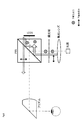
- FIG. 1 is a block diagram showing an outline of the configuration of an eyepiece video display apparatus according to the present invention.
- FIG. 2 is a block diagram showing the polarization state and traveling direction of light in the eyepiece image display apparatus according to the present invention.
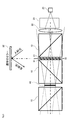
- FIG. 3 is a model of the optical path in the eyepiece image display apparatus according to the present invention, and shows an example in which a normal mirror is used.
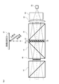
- FIG. 4 shows a model of the optical path in the eyepiece image display device according to the present invention, and shows an example in which a retroreflective mirror is used.
- FIG. 5 is a block diagram showing an outline of a conventional eyepiece image display device equipped with a reflective liquid crystal.
- FIG. 1 schematically shows a configuration of an eyepiece video display device 100 according to an embodiment of the present invention.
- FIG. 2 schematically shows the polarization state of light and the traveling direction thereof in the eyepiece image display apparatus 100 according to the embodiment of the present invention.
- the eyepiece image display device 100 includes a display optical system 1 and an eyepiece optical system 2.
- the display optical system 1 includes a light source and an image element such as a liquid crystal display, and generates desired image light and emits it toward the eyepiece optical system 2.
- the eyepiece optical system 2 includes an optical element such as a prism, and guides the image light emitted from the display optical system 1 to the observer's pupil E. For this reason, the eyepiece optical system 2 is disposed in the vicinity of the pupil E of the observer. Thereby, the observer can visually recognize the virtual image of the image displayed by the display optical system 1.
- the display optical system 1 includes a polarized light separating element 10, a light source 20, a polarizing plate 21 (first polarizing plate 21 a and / or second polarizing plate 21 b), a condensing lens 22, and a homogenizing element 23. , The reflection unit 30, and the reflection type image element 40.
- the polarization separation element 10 is an optical element that reflects the first polarization component light that is linearly polarized light and transmits the second polarization component light that is linearly polarized light having a polarization plane different from that of the first polarization component light.
- a polarization beam splitter PBS: Polarizing Beam Splitter
- a known light separation polarization element such as a wire grid polarizer may be used.
- the polarization separation element 10 has a structure in which two right angle prisms are bonded together, and a coating such as a dielectric multilayer film or a metal thin film is applied to the joint surface between the right angle prisms. Therefore, this bonding surface functions as a polarization separation surface 11 that transmits or separates light according to its polarization state.
- the polarization separation surface 11 reflects the S-polarized component light at a substantially right angle when the S-polarized component light is incident on this surface. When P-polarized component light is incident, the P-polarized component light is transmitted.
- the polarization separation surface 11 a material that reflects P-polarized component light and transmits S-polarized component light can also be used.
- the S-polarized component light is a light component that reflects the polarization separation surface 11 (first polarization component light)
- the P-polarization component light is a light component that transmits the polarization separation surface 11 (second polarization component). The case of light) will be described as an example.
- the light source 20 outputs light to the polarization separation element 10.
- the light source 20 is connected to a control circuit and a power source (not shown), and outputs light according to the control of the control circuit.
- a known light emitting diode (LED) can be used as the light source 20 .
- the output light from the light source 20 includes at least S-polarized component light (first polarized component light), and may also include P-polarized component light (second polarized component light) in addition to this. Good.
- a first polarizing plate 21 a, a condenser lens 22, and a uniformizing element 23 are disposed between the polarization separation element 10 and the light source 20.
- the output light from the light source 20 is guided to the polarization separation element 10 by a condenser lens 22 such as a telecentric lens after the illuminance and the like are made uniform by the uniformizing element 23.
- a first polarizing plate 21 a is disposed between the condenser lens 22 and the polarization separation element 10. The first polarizing plate 21a transmits the S-polarized component light included in the output light from the light source 20, and blocks the P-polarized component light.
- a second polarizing plate 21 b can be provided between the polarization separation element 10 and the eyepiece optical system 2. Similar to the first polarizing plate 21a, the second polarizing plate 21b transmits S-polarized component light and blocks P-polarized component light. Thus, by providing both or either one of the first polarizing plate 21a and the second polarizing plate 21b, unnecessary light can be prevented from entering the display optical system 1. As these polarizing plates 21 (the first polarizing plate 21a and / or the second polarizing plate 21b), the condensing lens 22, and the homogenizing element 23, known optical elements can be appropriately used.
- the reflection unit 30 has a function of converting the polarization state of incident light and a function of reflecting incident light.
- the reflection unit 30 is disposed at a position where the output light (S-polarized component light) from the light source 20 reflected on the polarization separation surface 11 of the polarization separation element 10 is incident.
- the reflection unit 30 includes a quarter wavelength plate 31 and a mirror 32.
- the quarter wavelength plate 31 converts the polarization state of incident light from linearly polarized light to circularly polarized light or from circularly polarized light to linearly polarized light.
- the quarter wavelength plate 31 is disposed between the polarization separation element 10 and the mirror 32.
- the quarter wavelength plate 31 converts the polarization state of the S-polarized component light reflected by the polarization separation element 10 from linearly polarized light to circularly polarized light, and reconverts the circularly polarized light reflected by the mirror 32 into linearly polarized light. To do. Further, when the circularly polarized light reflected by the mirror 32 is reconverted into linearly polarized light, the quarter wavelength plate 31 shifts the phase of the transmitted light again by 90 degrees and outputs it. . That is, when the light incident on the quarter-wave plate 31 is S-polarized component light, the light reflected by the mirror 32 and transmitted again through the quarter-wave plate 31 becomes P-polarized component light.
- the reflection unit 30 including the quarter wavelength plate 31 and the mirror 32 converts the S-polarized component light (first polarized component light) into the P-polarized component light (second polarized component light). It has a function to do.
- the mirror 32 it is preferable to employ a retroreflective mirror that can reflect (retroreflect) incident light in the incident direction.
- a normal mirror having the same incident angle and reflection angle can be adopted. Details of the merit of adopting the retroreflective mirror will be described later.
- the reflection-type image element 40 is an optical member that reflects incident light and generates image light for allowing an observer to visually recognize the incident light (reflected light) by performing predetermined modulation.
- the reflective image element 40 for example, a known reflective liquid crystal display can be used.
- the reflection type image element 40 is disposed at a position facing the reflection unit 30 (particularly the mirror 32) with the polarization separation element 10 interposed therebetween. For this reason, out of the reflected light reflected by the reflection unit 30, the light (P-polarized component light) transmitted through the polarization separation element 10 is incident on the reflective image element 40.
- the reflective image element 40 modulates the P-polarized component light to generate image light including at least the S-polarized component light, and reflects the image light toward the polarization separation element 10.
- the reflective image element 40 only needs to include at least S-polarized component light (first polarized component light), and in addition to this, P-polarized component light (second polarized component light) is included. It may be.
- the image light generated by the reflective image element 40 is incident on the polarization separation element 10, and the S polarization component light (first polarization component light) included in the image light is reflected at a substantially right angle on the polarization separation surface 11. Then, the P-polarized component light (second polarized component light) is transmitted.
- the image light of the S-polarized component light reflected by the polarization separation element 10 travels straight in the air and enters the eyepiece optical system 2.
- the eyepiece optical system 2 has a prism 50.
- the prism 50 is a light guide member (optical crystal) that guides image light inside.
- the prism 50 has, for example, a shape having an image light incident surface 51, a reflective surface 52, and an exit surface 53.
- the prism 50 may be configured by a single prism or may be configured by combining a plurality of prisms.
- the incident surface 51 of the prism 50 is provided in a direction perpendicular to the optical axis of the image light.
- the exit surface 53 is provided so as to face the pupil E of the observer.
- the reflection surface 52 has a rectangular shape (rectangular shape), for example, and functions as a means for bending the optical path of the image light at a right angle.
- the reflecting surface 52 enters the prism via the incident surface 51, reflects the image light at a substantially right angle, and emits it from the exit surface 53.
- the image light guided into the prism 50 of the eyepiece optical system 2 enters the observer's pupil E.
- the light output from the light source 20 is incident on the first polarizing plate 21 a via the homogenizing element 23 and the condenser lens 22.
- the first polarizing plate 21a transmits only the S-polarized component light (first polarized component light) in the output light from the light source 20, and blocks the P-polarized component light (second polarized component light).
- the S-polarized component light transmitted through the first polarizing plate 21 a enters the polarization separation element 10, is reflected at a substantially right angle on the polarization separation surface 11, and is guided to the reflection unit 30.
- the S-polarized component light is converted into circularly polarized light when passing through the quarter-wave plate 31, is reflected in the same direction as the incident direction by the mirror 32, and again passes through the quarter-wave plate 31. pass. At this time, the circularly polarized light reflected by the mirror 32 is converted into P-polarized component light.
- the P-polarized component light emitted from the reflection unit 30 in this way passes through the polarization separation element 10 and enters the reflection type image element 40.
- the reflective image element 40 modulates P-polarized component light to generate image light including at least S-polarized component light, and reflects the image light toward the polarization separation element 10.
- Video light including S-polarized component light is reflected at substantially right angles on the polarization separation surface 11 of the polarization separation element 10, propagates in the air, and is guided to the prism 50 constituting the eyepiece optical system 2.
- a second polarizing plate 21b may be provided between the polarization separation element 10 and the prism 50, instead of the first polarizing plate 21a or together with the first polarizing plate 21a.
- the P-polarized component light transmitted through the polarization separation element 10 may be blocked by the second polarizing plate 21b.
- the prism 50 guides the incident image light to the pupil E of the observer. Thereby, the light output from the light source 20 is modulated by the reflective image element 40 to generate image light, and this image light can be viewed by an observer.
- the light source 20, the polarization separation element 10, and the prism 50 can be arranged on a straight line. That is, the polarization separation element 10 and the prism 50 are located in the main optical axis direction of the light output from the light source 20. Therefore, according to the present invention, a slim configuration in which the light source 20, the polarization separation element 10, and the prism 50 are arranged in a straight line can be realized, and the eyepiece image display device 100 and the design of the HMD including the eyepiece image display device 100 can be realized. Can increase the degree of freedom.
- FIG. 3 is a model of an optical path in the eyepiece image display device 100, and shows an example in which a normal mirror is used.
- the normal mirror 32 has the same incident angle and reflection angle of light.
- the dispersion width of light propagating in the apparatus centering on the reflective image element 40 is shown in FIG.
- the light that travels toward is also emerging.
- the normal mirror 32 is used, the amount of light guided to the eyepiece optical system 2 out of the light output from the light source 20 is reduced, and the image visually recognized by the observer becomes dark.
- the intensity of the light output from the light source 20 has to be increased, which places a burden on the illumination system. Further, in order to prevent the light in the apparatus from leaking to the outside, it is necessary to increase the optical path length of the light or to increase the number of lenses for collecting the light. Then, when the normal mirror 32 is used, there are problems that the number of components of the device increases and the size of the device increases.
- FIG. 4 shows a model diagram when a retroreflective mirror is used as the mirror 32.
- the retroreflective mirror can reflect incident light in the incident direction (retroreflection).
- the retroreflective mirror 32 when the retroreflective mirror 32 is used, the dispersion width of the light propagating in the device is within the device as compared with the case of using the normal mirror shown in FIG. It has become narrower. That is, by using the retroreflective mirror 32, it is possible to prevent light from leaking from the inside of the apparatus to the outside. As a result, almost the entire amount of light output from the light source 20 can be guided to the reflection type image element 40, and further, almost all of the image light generated by the reflection type image element 40 is transferred to the eyepiece optical system 2. It is also possible to lead.
- the retroreflective mirror 32 the intensity of light output from the light source 20 can be set lower than when a normal mirror is employed. Thereby, the burden on the illumination system can be reduced, and the battery for driving the eyepiece image display device can be saved.
- the dispersion of light can be suppressed by using the retroreflective mirror 32, the optical path length of the light can be shortened.
- unnecessary optical parts such as lenses are unnecessary, and the configuration of the entire apparatus can be simplified. Therefore, by using the retroreflective mirror 32, a low-cost and compact eyepiece image display device 100 can be realized.
- the eyepiece video display device 100 of the present invention is preferably used as a video display device mounted on an HMD.
- the HMD is mounted around the user's head or neck, and has a structure in which the eyepiece optical system 2 of the eyepiece image display device 100 is disposed in front of one or both eyes of the user. is doing.
- various sensor devices such as a camera, a microphone, a gyro sensor, and an optical sensor can be mounted on the HMD.
- a known structure may be adopted as appropriate for the HMD.
- the configuration of the HMD disclosed in Japanese Patent No. 5420793 and Japanese Patent No. 5593429 can be adopted.
- the present invention relates to an eyepiece-type image display device mounted on an HMD or the like. Therefore, the present invention can be suitably used in the wearable device manufacturing industry.
Landscapes
- Physics & Mathematics (AREA)
- General Physics & Mathematics (AREA)
- Optics & Photonics (AREA)
Priority Applications (1)
| Application Number | Priority Date | Filing Date | Title |
|---|---|---|---|
| US15/551,273 US20180039065A1 (en) | 2015-02-16 | 2015-09-28 | Linearly disposed eyepiece video display |
Applications Claiming Priority (2)
| Application Number | Priority Date | Filing Date | Title |
|---|---|---|---|
| JP2015028072A JP6081508B2 (ja) | 2015-02-16 | 2015-02-16 | 直線配置型の接眼映像表示装置 |
| JP2015-028072 | 2015-02-16 |
Publications (1)
| Publication Number | Publication Date |
|---|---|
| WO2016132584A1 true WO2016132584A1 (ja) | 2016-08-25 |
Family
ID=56688855
Family Applications (1)
| Application Number | Title | Priority Date | Filing Date |
|---|---|---|---|
| PCT/JP2015/077270 Ceased WO2016132584A1 (ja) | 2015-02-16 | 2015-09-28 | 直線配置型の接眼映像表示装置 |
Country Status (3)
| Country | Link |
|---|---|
| US (1) | US20180039065A1 (OSRAM) |
| JP (1) | JP6081508B2 (OSRAM) |
| WO (1) | WO2016132584A1 (OSRAM) |
Families Citing this family (6)
| Publication number | Priority date | Publication date | Assignee | Title |
|---|---|---|---|---|
| CN107422484B (zh) * | 2017-09-19 | 2023-07-28 | 歌尔光学科技有限公司 | 棱镜式ar显示装置 |
| CN108459416B (zh) * | 2018-04-12 | 2021-08-06 | 京东方科技集团股份有限公司 | 照明装置、显示设备及近眼显示系统 |
| JP2019197124A (ja) * | 2018-05-09 | 2019-11-14 | セイコーエプソン株式会社 | 投写型表示装置 |
| CN110501813B (zh) * | 2018-05-17 | 2021-08-31 | 中强光电股份有限公司 | 显示装置 |
| JP2022156074A (ja) * | 2021-03-31 | 2022-10-14 | セイコーエプソン株式会社 | 光学モジュール及び頭部装着型表示装置 |
| CN114355501A (zh) * | 2022-01-27 | 2022-04-15 | 珠海莫界科技有限公司 | 一种光学显示模组 |
Citations (4)
| Publication number | Priority date | Publication date | Assignee | Title |
|---|---|---|---|---|
| JP2001117045A (ja) * | 1999-10-21 | 2001-04-27 | Shimadzu Corp | 表示装置 |
| JP2001177851A (ja) * | 1999-12-17 | 2001-06-29 | Minolta Co Ltd | 頭部搭載型映像表示装置 |
| JP2004527801A (ja) * | 2001-05-26 | 2004-09-09 | テイリズ オプティクス リミテッド | 偏光ビーススプリッタを使用する光学装置 |
| JP2010282231A (ja) * | 2004-03-29 | 2010-12-16 | Sony Corp | 画像表示装置 |
Family Cites Families (9)
| Publication number | Priority date | Publication date | Assignee | Title |
|---|---|---|---|---|
| US3677621A (en) * | 1969-11-24 | 1972-07-18 | Vickers Ltd | Optical field flattening devices |
| US3704061A (en) * | 1970-03-25 | 1972-11-28 | David Neil Travis | Wavelength selective mirror systems |
| US5383053A (en) * | 1992-04-07 | 1995-01-17 | Hughes Aircraft Company | Virtual image display having a high efficiency grid beamsplitter |
| US5596451A (en) * | 1995-01-30 | 1997-01-21 | Displaytech, Inc. | Miniature image generator including optics arrangement |
| US6310713B2 (en) * | 1997-04-07 | 2001-10-30 | International Business Machines Corporation | Optical system for miniature personal displays using reflective light valves |
| JP4341108B2 (ja) * | 1999-07-14 | 2009-10-07 | ソニー株式会社 | 虚像観察光学装置 |
| US6693743B2 (en) * | 2000-06-07 | 2004-02-17 | Cirvine Corporation | Birefringent devices |
| JP3966003B2 (ja) * | 2002-02-05 | 2007-08-29 | 日産自動車株式会社 | 内燃機関 |
| US7675684B1 (en) * | 2007-07-09 | 2010-03-09 | NVIS Inc. | Compact optical system |
-
2015
- 2015-02-16 JP JP2015028072A patent/JP6081508B2/ja active Active
- 2015-09-28 US US15/551,273 patent/US20180039065A1/en not_active Abandoned
- 2015-09-28 WO PCT/JP2015/077270 patent/WO2016132584A1/ja not_active Ceased
Patent Citations (4)
| Publication number | Priority date | Publication date | Assignee | Title |
|---|---|---|---|---|
| JP2001117045A (ja) * | 1999-10-21 | 2001-04-27 | Shimadzu Corp | 表示装置 |
| JP2001177851A (ja) * | 1999-12-17 | 2001-06-29 | Minolta Co Ltd | 頭部搭載型映像表示装置 |
| JP2004527801A (ja) * | 2001-05-26 | 2004-09-09 | テイリズ オプティクス リミテッド | 偏光ビーススプリッタを使用する光学装置 |
| JP2010282231A (ja) * | 2004-03-29 | 2010-12-16 | Sony Corp | 画像表示装置 |
Also Published As
| Publication number | Publication date |
|---|---|
| US20180039065A1 (en) | 2018-02-08 |
| JP6081508B2 (ja) | 2017-02-15 |
| JP2016151626A (ja) | 2016-08-22 |
Similar Documents
| Publication | Publication Date | Title |
|---|---|---|
| US11415812B2 (en) | Compact collimating optical device and system | |
| US10386563B2 (en) | Illuminator for a wearable display | |
| JP6081508B2 (ja) | 直線配置型の接眼映像表示装置 | |
| CN106133569B (zh) | 用于头可穿戴式显示器的具有多个内耦合全息图的光波导 | |
| KR102323214B1 (ko) | 증강현실을 위한 광학장치 | |
| CN103765294B (zh) | 用于头戴式显示器的轻质目镜 | |
| US8651726B2 (en) | Efficient polarized directional backlight | |
| US10007121B2 (en) | See-through head-mounted display | |
| CN112969955A (zh) | 具有二向色分束器颜色组合器的光学装置和系统 | |
| US20170115484A1 (en) | Image display device | |
| US11598971B2 (en) | Image device with a compact homogenizer | |
| JP2013114022A (ja) | 偏光装置及び表示装置 | |
| CN111158143B (zh) | 用于近眼显示设备的微型投影光引擎 | |
| WO2015007201A1 (zh) | 可佩带的平视光学系统 | |
| CN104136975B (zh) | 显示装置 | |
| JP2017058400A (ja) | 画像表示装置 | |
| EP3451047B1 (en) | Display apparatus and vehicular head-up display | |
| US11899210B2 (en) | Wearable image display device | |
| CN219799825U (zh) | 导光系统、光源装置及显示设备 | |
| CN103718089B (zh) | 投影装置 | |
| TW202409470A (zh) | 包含自由形式體積光柵的光導顯示系統 | |
| JP2018004764A (ja) | 映像表示装置及び接眼光学系 | |
| KR20070100460A (ko) | 헤드 마운티드 디스플레이 광학계 | |
| WO2011125479A1 (ja) | 偏光導光板、照明装置および投射型表示装置 |
Legal Events
| Date | Code | Title | Description |
|---|---|---|---|
| 121 | Ep: the epo has been informed by wipo that ep was designated in this application |
Ref document number: 15882685 Country of ref document: EP Kind code of ref document: A1 |
|
| WWE | Wipo information: entry into national phase |
Ref document number: 15551273 Country of ref document: US |
|
| NENP | Non-entry into the national phase |
Ref country code: DE |
|
| 122 | Ep: pct application non-entry in european phase |
Ref document number: 15882685 Country of ref document: EP Kind code of ref document: A1 |