WO2016129752A1 - Antenne de communication sans fil en champ proche et terminal portatif - Google Patents
Antenne de communication sans fil en champ proche et terminal portatif Download PDFInfo
- Publication number
- WO2016129752A1 WO2016129752A1 PCT/KR2015/005978 KR2015005978W WO2016129752A1 WO 2016129752 A1 WO2016129752 A1 WO 2016129752A1 KR 2015005978 W KR2015005978 W KR 2015005978W WO 2016129752 A1 WO2016129752 A1 WO 2016129752A1
- Authority
- WO
- WIPO (PCT)
- Prior art keywords
- metal plate
- antenna
- wireless communication
- range wireless
- short
- Prior art date
Links
Images


Classifications
-
- G—PHYSICS
- G06—COMPUTING; CALCULATING OR COUNTING
- G06K—GRAPHICAL DATA READING; PRESENTATION OF DATA; RECORD CARRIERS; HANDLING RECORD CARRIERS
- G06K19/00—Record carriers for use with machines and with at least a part designed to carry digital markings
- G06K19/06—Record carriers for use with machines and with at least a part designed to carry digital markings characterised by the kind of the digital marking, e.g. shape, nature, code
- G06K19/067—Record carriers with conductive marks, printed circuits or semiconductor circuit elements, e.g. credit or identity cards also with resonating or responding marks without active components
- G06K19/07—Record carriers with conductive marks, printed circuits or semiconductor circuit elements, e.g. credit or identity cards also with resonating or responding marks without active components with integrated circuit chips
- G06K19/077—Constructional details, e.g. mounting of circuits in the carrier
-
- H—ELECTRICITY
- H01—ELECTRIC ELEMENTS
- H01Q—ANTENNAS, i.e. RADIO AERIALS
- H01Q7/00—Loop antennas with a substantially uniform current distribution around the loop and having a directional radiation pattern in a plane perpendicular to the plane of the loop
-
- G—PHYSICS
- G06—COMPUTING; CALCULATING OR COUNTING
- G06K—GRAPHICAL DATA READING; PRESENTATION OF DATA; RECORD CARRIERS; HANDLING RECORD CARRIERS
- G06K19/00—Record carriers for use with machines and with at least a part designed to carry digital markings
- G06K19/06—Record carriers for use with machines and with at least a part designed to carry digital markings characterised by the kind of the digital marking, e.g. shape, nature, code
- G06K19/067—Record carriers with conductive marks, printed circuits or semiconductor circuit elements, e.g. credit or identity cards also with resonating or responding marks without active components
- G06K19/07—Record carriers with conductive marks, printed circuits or semiconductor circuit elements, e.g. credit or identity cards also with resonating or responding marks without active components with integrated circuit chips
- G06K19/077—Constructional details, e.g. mounting of circuits in the carrier
- G06K19/07749—Constructional details, e.g. mounting of circuits in the carrier the record carrier being capable of non-contact communication, e.g. constructional details of the antenna of a non-contact smart card
- G06K19/07773—Antenna details
- G06K19/07777—Antenna details the antenna being of the inductive type
- G06K19/07779—Antenna details the antenna being of the inductive type the inductive antenna being a coil
-
- H—ELECTRICITY
- H01—ELECTRIC ELEMENTS
- H01Q—ANTENNAS, i.e. RADIO AERIALS
- H01Q1/00—Details of, or arrangements associated with, antennas
- H01Q1/12—Supports; Mounting means
- H01Q1/22—Supports; Mounting means by structural association with other equipment or articles
-
- H—ELECTRICITY
- H01—ELECTRIC ELEMENTS
- H01Q—ANTENNAS, i.e. RADIO AERIALS
- H01Q1/00—Details of, or arrangements associated with, antennas
- H01Q1/12—Supports; Mounting means
- H01Q1/22—Supports; Mounting means by structural association with other equipment or articles
- H01Q1/2208—Supports; Mounting means by structural association with other equipment or articles associated with components used in interrogation type services, i.e. in systems for information exchange between an interrogator/reader and a tag/transponder, e.g. in Radio Frequency Identification [RFID] systems
- H01Q1/2225—Supports; Mounting means by structural association with other equipment or articles associated with components used in interrogation type services, i.e. in systems for information exchange between an interrogator/reader and a tag/transponder, e.g. in Radio Frequency Identification [RFID] systems used in active tags, i.e. provided with its own power source or in passive tags, i.e. deriving power from RF signal
-
- H—ELECTRICITY
- H01—ELECTRIC ELEMENTS
- H01Q—ANTENNAS, i.e. RADIO AERIALS
- H01Q1/00—Details of, or arrangements associated with, antennas
- H01Q1/12—Supports; Mounting means
- H01Q1/22—Supports; Mounting means by structural association with other equipment or articles
- H01Q1/24—Supports; Mounting means by structural association with other equipment or articles with receiving set
- H01Q1/241—Supports; Mounting means by structural association with other equipment or articles with receiving set used in mobile communications, e.g. GSM
- H01Q1/242—Supports; Mounting means by structural association with other equipment or articles with receiving set used in mobile communications, e.g. GSM specially adapted for hand-held use
- H01Q1/243—Supports; Mounting means by structural association with other equipment or articles with receiving set used in mobile communications, e.g. GSM specially adapted for hand-held use with built-in antennas
Definitions
- the present invention relates to a short range wireless communication antenna and a portable terminal, and more particularly, to a short range wireless communication antenna and a portable terminal for maximizing wireless communication efficiency.
- a mobile terminal is an intelligent terminal that adds computer-assisted functions such as Internet communication and information retrieval to a mobile phone.
- a mobile phone that allows a user to use the Internet and various applications (applications) while watching a window displaying a screen is an example.
- such a mobile terminal is equipped with NFC to enable near field communication.
- Korean Patent Application Publication No. 2013-0113222 (Antenna and a mobile terminal having the same) may be introduced.
- FIG. 1A is a block diagram of a mobile terminal associated with the prior art document 1.
- the mobile terminal 100 includes a wireless communication unit 110, an A / V (Audio / Video) input unit 120, a user input unit 130, a sensing unit 140, an output unit 150,
- the memory 160, the interface unit 170, the controller 180, and the power supply unit 190 may be included.
- the wireless communication unit 110 may include a broadcast receiving module 111, a mobile communication module 112, a wireless internet module 113, a short range communication module 114, a location information module 115, and the like.
- the audio / video input unit 120 is for inputting an audio signal or a video signal, and may include a camera 121 and a microphone 122, and the user input unit 130 may include the front and rear surfaces of the mobile terminal 100. Or it may be composed of a button 136 located on the side, a touch sensor (static pressure / electrostatic; 137).
- the sensing unit 140 detects a current state of the mobile terminal 100 such as an open / closed state of the mobile terminal 100, a location of the mobile terminal 100, presence or absence of a user contact, orientation of the mobile terminal, acceleration / deceleration of the mobile terminal, and the like.
- a sensing signal for controlling the operation of the mobile terminal 100 and may include a proximity sensor 141
- the output unit 150 is for generating an output related to the visual, auditory or tactile, etc.
- the display unit 151 may include a sound output module 152, an alarm unit 153, and a haptic module 154.
- the memory unit 160 may store a program for processing and controlling the controller 180, and temporarily stores input / output data (for example, a phone book, a message, an audio, a still image, a video, etc.). It can also perform a function for.
- input / output data for example, a phone book, a message, an audio, a still image, a video, etc.
- the interface unit 170 serves as a path with all external devices connected to the mobile terminal 100.
- the interface unit 170 receives data from an external device, receives power, transfers the power to each component inside the mobile terminal 100, or transmits data inside the mobile terminal 100 to an external device.
- wired / wireless headset ports, external charger ports, wired / wireless data ports, memory card ports, ports for connecting devices with identification modules, audio input / output (I / O) ports, The video input / output (I / O) port, the earphone port, and the like may be included in the interface unit 170.
- the controller 180 typically controls the overall operation of the mobile terminal. For example, it performs related control and processing for voice call, data communication, video call and the like.
- the controller 180 may include a multimedia module 181 for playing multimedia.
- the power supply unit 190 receives an external power source and an internal power source under the control of the controller 180 to supply power for operation of each component.
- the power supply unit 190 may include, for example, a battery, a connection port, a power supply control unit, and a charging monitoring unit.
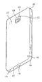
- FIG. 1B is a rear perspective view of the mobile terminal according to the prior art document 1.
- a camera 121 ′ may be additionally mounted on the rear surface of the terminal body, that is, the rear case 102.
- the flash 123 and the mirror 124 may be further disposed adjacent to the camera 121 ′.
- the flash 123 shines light toward the subject when the subject is photographed by the camera 121 '.
- 1C is a plan view showing that the antenna 200 according to the prior art document is attached to the rear cover 103 of the mobile terminal 100.
- the front case 101, the rear case 102, the rear cover (or the battery cover 103), the camera 121 ', the interface 170, the microphone 122, the sound output unit 152 ′, battery 191, battery mount 104, USIM card mount 105, and memory card mount 106 are shown.
- the surface of the rear case 102 may have a space in which external components such as a battery mounting unit 104, a USIM card mounting unit 105, and a memory card mounting unit 106 may be mounted.
- the exterior parts mounted on the surface of the rear case 102 are intended to expand the functions of the mobile terminal 100 in order to satisfy the demands of the diversified and diversified functions of the mobile terminal 100. .
- an antenna 200 for receiving broadcast information such as an electronic program guide (EPG) of digital multimedia broadcasting (DMB) or an electronic service guide (ESG) of digital video broadcast-handheld (DVB-H), Wibro,
- Antenna 200 for wireless Internet such as HSDPA, GSM, CDMA, WCDMA, LTE, Bluetooth, Short Range Communication (Bluetooth), RFID (Radio Frequency Identification), Infrared Data (IrDA), Ultra Wideband (UWB), antenna 200 for ZigBee short-range wireless communication is required.
- EPG electronic program guide
- ESG electronic service guide
- Antenna 200 for wireless Internet such as HSDPA, GSM, CDMA, WCDMA, LTE, Bluetooth, Short Range Communication (Bluetooth), RFID (Radio Frequency Identification), Infrared Data (IrDA), Ultra Wideband (UWB), antenna 200 for ZigBee short-range wireless communication is required.
- the antenna 200 is preferably formed in a large area for receiving radio waves, and is preferably located on the surface of the mobile terminal 100 in order not to be affected by other electronic components. Accordingly, as shown in FIG. 1C, the antenna 200 is disposed on the rear cover 103 that can secure a large area because electronic components are not generally mounted.
- the antenna 200 of the prior art document 1 includes a flexible substrate 210, two types of patterns, and a magnetic sheet 230 as main components.
- the pattern is largely divided into two types, the high frequency pattern 220 and the low frequency pattern 225. That is, different frequency bands are used, and the high frequency pattern 220 is suitable for wireless communication, and the low frequency pattern 225 is mainly suitable for wireless charging of a battery.
- Wireless charging technology used in the mobile terminal 100 uses the electromagnetic induction principle.
- Electromagnetic induction forms a magnetic field by flowing a current, and when the mobile terminal 100 is placed thereon, a current flows through the low frequency pattern, that is, the wireless charging coil 225 mounted on the mobile terminal 100, thereby charging.
- the frequency may vary depending on the amount of power to be transmitted, power used in small household appliances such as the mobile terminal 100 generally uses a relatively low frequency of several hundreds of kHz or less.
- Wireless communication requires an antenna for functions such as NFC (Near Field Communication) and RFID (Radio Frequency Identification) in addition to transmission of radio waves for a telephone call as the functions of the mobile terminal 100 are diversified.
- the frequency used by the wireless communication technology is different, and uses a relatively high frequency relative to the frequency used for wireless charging to transmit a large amount of data.
- NFC Near field communication
- Short-range wireless communication is a kind of RFID, a contactless wireless communication module using a frequency band of about 13.56MHz.
- the antenna according to the prior art document 1 and the mobile terminal having the same is to simply arrange the antenna 200 on the rear cover 103, in this case there is a problem that the wireless communication efficiency is greatly reduced.
- Korean Patent No. 1318707 (antenna device and mobile communication terminal) may be introduced.
- FIG. 2A shows a mobile communication terminal equipped with the antenna device according to the first embodiment of the prior art document 2, (A) is a rear view of the casing, and (B) is an A-A sectional view.
- the antenna device 1A according to the first embodiment of the prior art document 2 is the back side of the casing 5 of the mobile communication terminal (for example, a cellular phone), as shown in Figs. 2A and 2B.
- the power supply member 10 including the coil pattern 15 provided in the upper portion, the magnetic member 19 made of a ferrite sheet attached to the power supply member 10, and the radiation member 20.
- the radiating member 20 functions as an antenna for receiving a transmission signal and a receiving signal radiating a signal supplied from the power feeding member 10 and supplying it to the power feeding member 10. It is done by preparing a film or gourd.
- the power feeding member 10 is composed of a laminate in which a plurality of dielectric layers (thermoplastic resin sheets) are stacked, and the coil pattern 15 includes a plurality of annular conductors disposed in the plurality of dielectric layers, respectively, interlayer conductors such as via hole conductors (FIG. 2A). (B) is not shown) to be connected in a helical shape so as to have a winding axis in the stacking direction of the laminate, thereby forming a coil.
- Both ends of the coil pattern 15 are connected to a radio circuit such as an IC tag embedded in the casing 5.
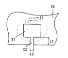
- the radiating member 20 has the opening part 21 and the slit part 22 which communicates from the edge of the opening part 21 in the one part.
- One end of the slit portion 22 is connected to the opening 21 and the other end is opened at the side edge of the radiating member 20. That is, the slit part 22 is provided so that the side edge of the opening part 21 and the radiation member 20 may communicate.
- the entire area of the opening 21 overlaps the inner region of the coil pattern 15, and the coil pattern 15 overlaps the radiating member 20.
- FIG. 2B is an explanatory view showing an exploded view of the antenna device according to the first embodiment of the prior art document 2.
- FIG. 2B is an explanatory view showing an exploded view of the antenna device according to the first embodiment of the prior art document 2.
- the assembly procedure of the antenna device 1A is as shown in FIG. 2B. First, the magnetic member 19 is attached to the power feeding member 10 having the coil pattern 15 embedded therein, and the power feeding member 10 is attached to the radiation member 20. FIG. Attach on).
- the radiating member (1A) transmits a transmission signal from a wireless circuit electrically connected to both ends of the coil pattern 15 by a power feeding member 10 including the coil pattern 15. 20, and a received signal (received power) from the radiating member 20 is supplied to the radio circuit through the feeding member 10.
- the opening 21 of the radiating member 20 and the inner region of the coil pattern 15 overlap each other.
- FIG. 2C is an explanatory diagram showing the coupling between the coil pattern and the radiation member in the antenna device of Embodiment 1 of the prior art document 2.
- FIG. 2C is an explanatory diagram showing the coupling between the coil pattern and the radiation member in the antenna device of Embodiment 1 of the prior art document 2.
- a signal current flows from the radio circuit to the coil pattern 15, and the induction magnetic field H generated by the current causes the opening 21 to be opened.
- the induction magnetic field H generated by the current causes the opening 21 to be opened.
- the ideal distribution of the magnetic field H means that the center B of the two magnetic fields H coincides with the center of the opening 21, and the gain of the radiating member 20 is maximized in this state.
- the induction magnetic field H generates induced currents I1 and I2 (however, the propagation directions of the currents I1 and I2 differ by 180 °) in the peripheral portion of the opening 21.
- FIG. 2E is an explanatory diagram showing an induced current flowing in the peripheral edge portion of the radiating member in the antenna device of Embodiment 1 of the prior art document
- FIG. 2F is the antenna device and the reader / writer side of Embodiment 1 of the prior art document 2 It is explanatory drawing which shows the magnetic coupling state of an antenna, (A) shows Example 1, (B) shows a comparative example.
- the current I2 is not shown in FIG. 2E, the current I2 flows in the opposite direction to the current I1.
- the induction currents I1 and I2 overlap the radiating member 20 and the coil pattern 15 in plan view, the induction currents I1 and I2 are different from the current flowing in the coil pattern 15 so as to block the induction magnetic field generated from the coil pattern 15. Flow in the opposite direction.
- the magnetic fields are generated from the radiating member 20 by the induced currents I1 and I2, and the inductive currents I1 and I2 flow through the radiating member 20.
- the radiating member 20 does not transmit magnetic flux so that the opening 21 of the radiating member 20 is closed. In the path of the inner side and the outer edge of the radiating member 20 to the outside, a loop having a relatively large magnetic flux ⁇ is drawn.
- the magnetic coupling state of the antenna device 1A and the antenna 40 of the reader / writer is as shown in Fig. 2F.
- the case where the radiation member 20 is omitted is shown in FIG. 2F (B) as a comparative example.
- the result of having measured the distance which can communicate with the antenna 40 of the reader / writer with respect to the various size (length and breadth size) of the power feeding member 10 is shown.
- the communication distance in the comparative example in which the radiation member 20 is omitted is shown.
- FIG. 2G is an operation explanatory diagram in the case where the radio signal is in the UHF band in the antenna device according to the first embodiment of the prior art document 2.
- FIG. 2G is an operation explanatory diagram in the case where the radio signal is in the UHF band in the antenna device according to the first embodiment of the prior art document 2.
- the magnetic field H is induced by the induction currents I1 and I2.
- the radio signal handled by the antenna device 1A is a high frequency band, particularly in the UHF band, FIG. 2G
- the electromagnetic field distribution is 2 across the radiating member 20 by the chain that the electric field E is induced by the magnetic field H and the magnetic field H is induced by the electric field E. Widen dimensionally.
- the radio signal is transmitted by this electromagnetic field distribution, and the communication distance can be widened by the induction currents I1 and I2 flowing through the entire radiating member 20.
- the slit portion 22 is connected to the opening portion 21, the flow of the induced currents I1 and I2 is restricted in the slit portion 22, so that a potential difference is provided (capacity is formed). Therefore, by controlling the amount or distribution of the induction currents I1 and I2 at the length L1 and the width L2 of the slit portion 22, the amount of electric and magnetic fields generated in the entire area of the radiating member 20 is controlled. can do. As a result, the gain of the transmission signal can be controlled.
- the gain of the radio signal transmitted / received to / from the radiating member 20 can be controlled by the length L1 or the width L2 of the slit portion 22. Specifically, the larger the length L1 of the slit portion 22, the smaller the width L2 tends to be.
- the annular conductors provided in the dielectric layers of the power feeding member 10 are preferably formed of a plurality of parallel line conductors at predetermined intervals. That is, in Example 1 of Prior Art Document 2, the conductor formed in an annular shape is formed as two parallel line conductors, whereby the magnetic flux passes between the two line conductors, and the excited magnetic field becomes wider in the center direction of the coil pattern 15, that is, the direction orthogonal to the winding axis, so that the magnetic flux can be efficiently used.
- the effect of reducing the DC resistance of the annular conductors is produced. As a result, the gain of the radio signal can be improved.
- the coil pattern 15 is shown as a power supply circuit.
- the coil patterns 15 are stacked as described above. Since it is formed by the annular electrode, the floating capacitance formed between the annular electrodes of each layer is used as a capacitance component.
- the power supply member 10 may include at least one coil pattern 15.
- the power supply circuit has a predetermined resonance frequency, for example, a capacitance component or an inductance component for adjusting the resonance frequency may be provided. You may have more.
- the power supply circuit (coil pattern 15) has a predetermined resonance frequency, and the frequency of the radio signal transmitted and received by the radiating member 20 corresponds substantially to this resonance frequency.
- substantially substantial means that the band of the resonant frequency of the power feeding circuit and the frequency band of the radio signal transmitted / received by the radiating member 20 substantially match.
- the frequency of the transmission signal and / or the reception signal substantially corresponds to the resonance frequency of the power supply circuit, the shape and material of the radiating member 20, the shape of the casing 5 supporting the radiating member 20, An antenna device having stable frequency characteristics that are almost independent of material and the like is obtained.
- the frequency band of the radio signal is While being determined, matching of impedance between the radiating member 20 and the radio circuit (signal processing section) is also realized.
- the antenna apparatus corresponding to various mobile communication terminals can be realized without changing the shape of the opening part 21, the slit part 22, or the shape of the coil pattern 15 of the radiation member 20.
- the magnetic member 19 superposed on the power feeding member 10 effectively couples the magnetic field generated in the coil pattern 15 to the radiation member 20 so as not to leak to the outside, and also blocks the magnetic field generated from the outside. Therefore, it has a function to prevent deterioration of communication performance.
- Example 1 of the prior art document 2 since the power feeding member 10 and the radiating member 20 are electromagnetically coupled, it is not necessary to consider the impedance matching between the feeding member 10 and the radiating member 20. .
- the gain of the radio signal can be controlled very easily.
- the opening 21 of the radiating member 20 and the inner region of the coil pattern 15 overlap almost the entire area, and the area of the opening 21 and the inner region of the coil pattern 15 are substantially the same.
- the opening 21 and the inner region of the coil pattern 15 may overlap at least in part, and the radiation member 20 and the coil pattern 15 may overlap in part.
- the area of the radiation member 20 is larger than the area of the part in which the coil pattern 15 was formed.
- the communication current can be further improved because the induced current flows in a large loop.
- the power supply member 10 may be a coil pattern 15 formed on a single layer substrate.
- the antenna device and the mobile communication terminal according to the prior art document 2 has a disadvantage in that the coil pattern 15 simply overlaps with the radiating member 20 and thus does not maximize the wireless communication efficiency.
- An object of the present invention is to provide a short range wireless communication antenna and a portable terminal capable of maximizing wireless communication efficiency.
- a communication antenna and a portable terminal are provided.
- An object of the present invention is to maximize the signal power of the loop pattern to the metal plate via the start terminal and the jump contact and then to the end terminal through the jump contact again, so that the interworking with the antenna of the reader for short-range wireless communication
- the present invention is to provide a short range wireless communication antenna and a portable terminal which can be made more active to realize a far wider distance between the two and at the same time to ensure the efficiency of the short range wireless communication.
- the object of the present invention is that the signal power radiated by the metal plate together with the loop pattern of the feed sheet is formed in the Z-axis direction opposite to the antenna of the reader, so that the centering of the signal power between the two is extremely easy.
- the signal power radiated by the metal plate together with the loop pattern of the feed sheet is formed in the Z-axis direction opposite to the antenna of the reader, so that the centering of the signal power between the two is extremely easy.
- An object of the present invention is to provide a short range wireless communication antenna and a portable terminal capable of securing a relatively larger recognition distance.
- An object of the present invention is to flow the signal current to the metal plate via the start terminal and one jump contact and then to the end terminal through the other jump contact again to maximize the signal power as the expansion effect of the loop pattern to radiate To provide a short-range wireless communication antenna and a portable terminal that can further improve the wireless communication efficiency.
- An object of the present invention to provide a short-range wireless communication antenna and a portable terminal that can further maximize the radiation of signal power by magnetic force as well as electric force.
- the object of the present invention is that the loop pattern is patterned on the flexible film from the start terminal to the PCB jump contact, but is connected to the rear plate or the back cover, which is a neighboring metal plate through the jump contact, and consequently the flow of signal current is started between the start terminal and the jump. It leads to the rear plate or back cover which is a metal plate via the contact point, and then directly to the main PCB through the PCB jump contact point, and it can radiate by maximizing the signal power by reducing the terminal and expanding the loop pattern.
- the present invention provides a short range wireless communication antenna and a portable terminal which can further improve efficiency.
- the feed sheet is patterned on a flexible film overlapping the metal plate and at the same time has a short-term wireless communication with the metal plate facing the antenna of the reader through a jump contact connected to the metal plate with a start terminal and an end terminal. Including the loop pattern for maximizing and radiating the signal power for the technical features of the configuration.
- a portable terminal having a built-in short-range wireless communication antenna having a built-in short-range wireless communication antenna
- the rear plate or the back cover is made of a metal plate
- the feed sheet is patterned on a flexible film overlapping the metal plate and at the same time has a short-term wireless communication with the metal plate facing the antenna of the reader through a jump contact connected to the metal plate with a start terminal and an end terminal. Including the loop pattern for maximizing and radiating the signal power for the following features of the technical configuration.
- a portable terminal having a built-in short-range wireless communication antenna having a built-in short-range wireless communication antenna
- the rear plate or the back cover is made of a metal plate
- the feed sheet is patterned on a flexible film overlapping the metal plate and at the same time has a start terminal and a signal power for short-range wireless communication against the antenna of the reader with the metal plate through a jump contact connected to the metal plate. Including the loop pattern to maximize the radiation,
- the present invention has the effect of maximizing wireless communication efficiency.
- the flow of signal current leads to the metal plate via the start terminal and the jump contact point, and then to the end terminal through the jump contact point, thereby maximizing and radiating the signal power as an expansion effect of the loop pattern.
- the loop pattern is connected to the metal plate via the start terminal and the jump contact, and then to the end terminal through the jump contact, thereby maximizing the signal power.
- the interworking with the antenna of the reader for short-range wireless communication is further improved. Actively, the bilateral communication distance can be realized more widely and at the same time, the efficiency of short-range wireless communication can be guaranteed.
- the signal power radiated by the metal plate together with the loop pattern of the feed sheet is formed in the Z-axis direction opposite to the antenna of the reader, so that the centering of the signal power between the two is extremely easy.
- the present invention has the effect of relatively improving the wireless communication efficiency by utilizing the metal plate.
- the present invention has the effect of ensuring a relatively larger recognition distance.
- the flow of signal current leads to the metal plate via the start terminal and one jump contact, and then to the end terminal through the other jump contact, thereby maximizing the signal power as the expansion effect of the loop pattern, and wirelessly. There is an effect that can further improve the communication efficiency.
- the present invention has the effect of further maximizing the radiation of signal power by magnetic force as well as electric force.
- the present invention has the effect of further maximizing the radiation of the signal power through the gap, including the opening and the opening.
- the loop current is connected to the rear plate or the back cover, which is a neighboring metal plate, through the jump contact, and as a result, the flow of signal current leads to the start terminal and the jump contact. It leads to the rear plate or back cover, which is a metal plate, and then directly to the main PCB through the PCB jump contact, and maximizes the signal power as the expansion effect of the loop pattern and the expansion of the loop pattern. There is an effect that can be further improved.
- FIG. 1A is a block diagram of a mobile terminal associated with Prior Art Document 1.
- FIG. 1A is a block diagram of a mobile terminal associated with Prior Art Document 1.
- FIG. 1B is a rear perspective view of the mobile terminal according to the prior art document 1;
- Figure 1c is a plan view showing that the antenna is attached to the rear cover of the mobile terminal according to the prior art.
- FIG. 2A shows a mobile communication terminal equipped with an antenna device according to Embodiment 1 of the prior art document 2, (A) is a rear view of the casing, and (B) is an A-A sectional view.
- FIG. 2B is an explanatory view showing an exploded view of the antenna device according to the first embodiment of the prior art document 2.
- 2C is an explanatory diagram showing the coupling between the coil pattern and the radiation member in the antenna device of Embodiment 1 of the prior art document;
- FIG. 2D is an explanatory diagram showing an induced current generated around an opening of a radiating member in the antenna device according to the first embodiment of the prior art document 2.
- FIG. 2E is an explanatory diagram showing an induced current flowing in a peripheral edge portion of a radiation member in the antenna device of Embodiment 1 of the prior art document 2.
- FIG. 2E is an explanatory diagram showing an induced current flowing in a peripheral edge portion of a radiation member in the antenna device of Embodiment 1 of the prior art document 2.
- FIG. 2G is an operation explanatory diagram when the radio signal is in the UHF band in the antenna device according to the first embodiment of the prior art document 2.
- FIG. 2G is an operation explanatory diagram when the radio signal is in the UHF band in the antenna device according to the first embodiment of the prior art document 2.
- Figure 3a is an exploded perspective view including a reader for explaining a near field communication antenna according to a first embodiment of the present invention.
- 3B is a plan view illustrating a short range wireless communication antenna according to a first embodiment of the present invention
- Figure 4a is an exploded perspective view including a reader for explaining a near field communication antenna according to a second embodiment of the present invention.
- 4B is a plan view illustrating a short range wireless communication antenna according to a second embodiment of the present invention.
- Figure 5a is an exploded perspective view including a reader for explaining a near field communication antenna according to a third embodiment of the present invention.
- 5B is a plan view illustrating a short range wireless communication antenna according to a third embodiment of the present invention.
- Figure 6a is an exploded perspective view including a reader for explaining a near field communication antenna according to a fourth embodiment of the present invention.
- 6B is a plan view illustrating a short range wireless communication antenna according to a fourth embodiment of the present invention.
- 7a to 7e are simulation images showing the radiation state of the signal power of the short-range wireless communication antenna according to the present invention.
- Figure 8a is a graph for testing the performance of the antenna device NFC according to the prior art document 2.
- Figure 8b is a graph showing the performance of NFC, a near field communication antenna applied to the present invention.
- Figure 9 is a table comparing the performance of NFC as an antenna device according to the prior art document 2 and the short-range wireless communication antenna applied to the present invention.
- FIG. 10 is a block diagram for explaining a mobile terminal according to the present invention.
- 11A is an exploded perspective view showing a mobile terminal according to a fifth embodiment of the present invention.
- 11B is an exploded perspective view showing a mobile terminal according to a sixth embodiment of the present invention.
- FIG. 12A is an exploded perspective view showing a mobile terminal according to a seventh embodiment of the present invention.
- FIG. 12B is an exploded perspective view showing a mobile terminal according to an eighth embodiment of the present invention.
- the feed sheet is patterned on a flexible film overlapping the metal plate and at the same time has a short-term wireless communication with the metal plate facing the antenna of the reader through a jump contact connected to the metal plate with a start terminal and an end terminal. Including the loop pattern for maximizing and radiating the signal power for the technical features of the configuration.
- a portable terminal having a built-in short-range wireless communication antenna having a built-in short-range wireless communication antenna
- the rear plate or the back cover is made of a metal plate
- the feed sheet is patterned on a flexible film overlapping the metal plate and at the same time has a short-term wireless communication with the metal plate facing the antenna of the reader through a jump contact connected to the metal plate with a start terminal and an end terminal. Including the loop pattern for maximizing and radiating the signal power for the following features of the technical configuration.
- a portable terminal having a built-in short-range wireless communication antenna having a built-in short-range wireless communication antenna
- the rear plate or the back cover is made of a metal plate
- the feed sheet is patterned on a flexible film overlapping the metal plate and at the same time has a start terminal and a signal power for short-range wireless communication against the antenna of the reader with the metal plate through a jump contact connected to the metal plate. Including the loop pattern to maximize the radiation,
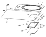
- FIG. 3A is an exploded perspective view illustrating a short range wireless communication antenna according to a first embodiment of the present invention
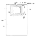
- FIG. 3B is a plan view illustrating a short range wireless communication antenna according to a first embodiment of the present invention
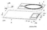
- FIG. 4A Is an exploded perspective view including a reader for explaining a short range wireless communication antenna according to a second embodiment of the present invention
- FIG. 4B is a plan view showing a short range wireless communication antenna according to a second embodiment of the present invention
- FIG. 6 is an exploded perspective view illustrating a short range wireless communication antenna according to a third embodiment of the present invention
- FIG. 5B is a plan view illustrating a short range wireless communication antenna according to a third embodiment of the present invention
- FIG. 6B is a fourth embodiment of the present invention.
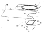
- the short range wireless communication antenna 100 is interlocked with the antenna A of the reader T for the short range wireless communication as shown in FIGS. 3A to 6D, and the metal plate 10 and the metal plate 10. It includes a feed sheet 20 overlapping).
- the power feeding sheet 20 is patterned on the flexible film 21 overlapping the metal plate 10, and at the same time, a jump contact 25 connected to the metal plate 10 having a start terminal 23 and an end terminal 24. It includes a loop pattern 22 to maximize the signal power for short-range wireless communication with the metal plate 10 and the antenna (A) of the reader (T) through the radiation.
- the loop pattern 22 is patterned on the flexible film 21 from the start terminal 23 to the end terminal 24, the loop pattern 22 is connected to the neighboring metal plate 10 through the jump contact 25, and as a result, the signal current The flow is led to the metal plate 10 via the start terminal 23 and the jump contact 25, and then to the end terminal 24 through the jump contact 25 again to signal the expansion of the loop pattern 22. Maximized power can be radiated to further improve wireless communication efficiency.
- 7A to 7E are simulation images showing the radiation state of the signal power of the short range wireless communication antenna according to the present invention.
- the loop pattern 22 leads to the metal plate 10 via the start terminal 23 and the jump contact 25, and then the end terminal 24 through the jump contact 25.
- the interworking with the antenna (A) of the reader (T) for short-range wireless communication is more active, which can realize a farther and wider communication distance between the two. It can be confirmed that the efficiency of the system can be ensured.
- the signal power radiated by the metal plate 10 together with the loop pattern 22 of the feed sheet 20 is the antenna of the reader T when the planes of the metal plate 10 are referred to as X and Y axes. It is formed in the Z-axis direction opposite to (A) to facilitate the centering of the signal power between the two to maximize the convenience of use as well as the expansion of the communication distance and communication width.
- FIG. 8A is a graph illustrating a test of the performance of NFC as an antenna device according to the prior art document 2
- FIG. 8B is a graph illustrating the performance of NFC as a short range wireless communication antenna applied to the present invention.
- the performance of the NFC device according to the prior art document 2 is -32.8029 dB at a frequency of 13.56 MHz
- the performance of the NFC of the short range wireless communication antenna 100 according to the present invention is illustrated in FIG. 8A.
- a loss of -29.5390 dB appears at a frequency of 13.56 MHz, and the difference between the two is about -3.3 dB, and the present invention can relatively improve wireless communication efficiency by utilizing the metal plate 10. can confirm.
- the loop pattern 22 according to the present invention can be utilized as NFC for the antenna A of the reader T.
- FIG. 9 is a table comparing the performance of NFC as an antenna device according to the prior art document 2 and the performance of NFC as a short range wireless communication antenna applied to the present invention.
- NFC Near Field Communication
- NFC is a kind of RFID, a non-contact wireless communication module using a frequency band of about 13.56 MHz, and the antenna of the reader T at a close distance of about 10 to 40 cm. It is a technology that transmits data between), and it is attracting attention as next-generation short-range communication technology that is attracting attention because of its relatively high security and low price because of its short communication distance, and it can use both data reading and writing, and it is set between devices like Bluetooth. There is no need for this, and the present invention can be suitably applied to the mobile terminal H of the present invention.
- the recognition distance of the antenna device NFC according to the prior art document 2 was only 28 mm, but the recognition distance of the NFC of the short range wireless communication antenna 100 applied to the present invention is 31 mm. It is possible to secure a larger recognition distance compared to Document 2.
- the metal plate 10 communicates with the opening 11 and the opening 11 for positioning the feed sheet 20 as shown in FIGS. 3A to 6B.
- a short-range radio as shown in FIGS. 7A to 7E having an open portion 12 and divided into one plate region 13 and the other plate region 14 by these openings 11 and the open portion 12. More actively interworking with the antenna A of the reader T for communication, as shown in FIGS. 8B and 9, the short range wireless communication antenna 100 of the present invention and the antenna A of the reader T communicate with each other. By making the distance farther and wider, ultimately, the efficiency of short-range wireless communications can be further improved.
- the jump contact 25 is one jump contact 25a, one jump contact 25a and one plate region 13 connected to supply the current supplied from the start terminal 23 to the one plate region 13. It may include the other jump contact (25b) connected to the other plate region 14 to supply the current through the sequential to the end terminal (24).
- the flow of the signal current is led to the metal plate 10 via the start terminal 23 and one jump contact 25a, and then to the end terminal 24 through the other jump contact 25b, and thus the loop pattern 22.
- the signal power can be maximized and radiated to further improve wireless communication efficiency.
- the feed sheet 20 includes a magnetic sheet 26 supporting the flexible film 21 to further maximize the radiation of signal power due to the magnetic force as well as the electric force, and the gap from the metal plate 10. Further comprising a sub-metal plate 30 spaced apart from the G) as shown in Figure 7a to 7e to emit radiation of the signal power through the gap (G) including the opening 11 and the open portion 12 It is desirable to be able to maximize further.
- FIG. 10 is a block diagram illustrating a portable terminal according to the present invention
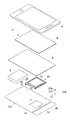
- FIG. 11A is an exploded perspective view showing a portable terminal according to a fifth embodiment of the present invention
- FIG. 11B illustrates a portable terminal according to a sixth embodiment of the present invention.
- the mobile terminal H has a front frame F for fixing the display module D showing an image as shown in FIGS. 10 to 11B, and a rear plate R for supporting the display module D. ), A back cover (C) assembled while protecting the main PCB (P) and the battery (B) assembled to the rear plate (R), and the antenna (A) of the reader (T) for short-range wireless communication It consists of a configuration incorporating a short range wireless communication antenna 100 (other configurations may also be assembled but will be omitted in the present invention in order to avoid complications in the description).
- the rear plate (R) or the back cover (C) is made of a metal plate 10
- the mobile terminal (H) according to the present invention is a rear plate (R) or back cover (C) which is a metal plate (10)
- a power feeding sheet 20 overlapping each other, wherein the power feeding sheet 20 is patterned on the flexible film 21 overlapping the rear plate R or the back cover C, which is the metal plate 10, and simultaneously started.
- the reader T together with the metal plate 10 through a jump contact 25 connected to the rear plate R or the back cover C, which is a metal plate 10, having a terminal 23 and an end terminal 24.
- Opposed to the antenna (A) of the includes a loop pattern 22 for maximizing and radiating the signal power for short-range wireless communication.
- the mobile terminal H can produce the rear plate R as the metal plate 10 as shown in FIG. 11A, and the back cover C as the metal plate as shown in FIG. 11B.
- the rear plate (R) is a metal plate
- the feed sheet 20 is a flexible film overlapping the rear plate (R) of the metal plate 10, as shown in Figure 11a
- the feed sheet 20 is shown in Fig.
- the back cover C which is the metal plate 10
- the back cover C is patterned on the flexible film 21 overlapping the back cover C, which is the metal plate 10, and has the start terminal 23 and the end terminal 24.
- the roof pattern 22 is patterned on the flexible film 21 from the start terminal 23 to the end terminal 24, the rear plate R or the bag, which is the metal plate 10 neighboring through the jump contact 25, is formed. Connected to the cover C and consequently the flow of signal current leads to the rear plate R or the back cover C, which is the metal plate 10, via the start terminal 23 and the jump contact 25, and then jumps again. It is connected to the end terminal 24 through the contact 25 to maximize the signal power as the expansion effect of the loop pattern 22 can be radiated to further improve the wireless communication efficiency.
- the loop pattern 22 is connected to the rear plate R or the back cover C, which is the metal plate 10, via the start terminal 23 and the jump contact 25.
- the jump contact (25) through the end terminal (24) to maximize the signal power can be maximized the interworking with the antenna (A) of the reader (T) for short-range wireless communication communication distance between the two Can be implemented far and wider, while ensuring the efficiency of short-range wireless communications.
- the signal power radiated by the metal plate 10 together with the loop pattern 22 of the power feeding sheet 20 is X-axis on the plane of the rear plate R and the back cover C, which are the metal plates 10.
- the Y-axis which is formed in the Z-axis direction opposite to the antenna A of the reader T to facilitate centering of signal power between the two, thereby maximizing the convenience of use and the extension of the communication distance and communication width. You can do it.
- the loop pattern 22 according to the present invention may be utilized as NFC for the antenna A of the reader T, and as shown in the table of FIG.
- the recognition distance was only 28 mm
- the recognition distance of NFC which is the short-range wireless communication antenna 100 applied to the mobile terminal H of the present invention, was 31 mm, and it was confirmed that a relatively larger recognition distance than the prior art document 2 can be obtained. Can be.
- the rear case or the back cover C which is the metal plate 10
- an open portion 12 communicating with the opening 11, and divided into one plate region 13 and the other plate region 14 by the openings 11 and the open portions 12.
- the antenna A of the reader T for near field communication is more actively linked to the near field communication antenna 100 and the reader of the present invention as shown in FIGS. 8B and 9.
- the jump contact 25 is one jump contact 25a, one jump contact 25a and one plate region 13 connected to supply the current supplied from the start terminal 23 to the one plate region 13. It may include the other jump contact (25b) connected to the other plate region 14 to supply the current through the sequential to the end terminal (24).
- the flow of the signal current leads to the rear case or the back cover C, which is the metal plate 10, via the start terminal 23 and the one jump contact 25a, and then through the other jump contact 25b to the end terminal 24. ) To be maximized the signal power as the expansion effect of the loop pattern 22 to be radiated to further improve the wireless communication efficiency.
- the feed sheet 20 includes a magnetic sheet 26 supporting the flexible film 21 to maximize the radiation of the signal power by the magnetic force as well as the electrical force, as shown in Figure 11b Further comprising a sub-metal plate 30 spaced apart from the back cover C, which is a plate 10, with a gap G, as shown in FIGS. 7A to 7E, the opening 11 and the open portion 12. Of course, through the gap (G) can be further maximized the emission of signal power.
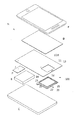
- FIG. 12A is an exploded perspective view of a mobile terminal according to a seventh embodiment of the present invention
- FIG. 12B is an exploded perspective view of a mobile terminal according to an eighth embodiment of the present invention.
- the portable terminal H has a front frame F for fixing the display module D showing an image and a rear for supporting the display module D as shown in FIGS. 10 and 12A and 12B.
- It is composed of a built-in short-range wireless communication antenna 100 to be interlocked with (other components may be assembled but will be omitted in the present invention to avoid the complexity of the description).
- the rear plate (R) or the back cover (C) is made of a metal plate 10
- the mobile terminal (H) according to the present invention overlaps the rear plate (R) or back cover which is the metal plate 10
- a feed sheet 20 wherein the feed sheet 20 is patterned on the flexible film 21 overlapping the rear plate R or the back cover C, which is the metal plate 10, and at the same time, the start terminal 23.
- the rear plate (R) or the back cover (C) of the metal plate 10 through a jump contact 25 connected to the rear plate (R) or the back cover (C) of the metal plate 10 having a
- the rear plate (R) which includes a loop pattern (22) for maximizing and radiating signal power for short-range wireless communication, facing the antenna (A) of the reader (T), and the start terminal (23) and the metal plate (10).
- the current through the back cover (C) to the main PCB (P) which includes a PCB contact the jump (J).
- the portable terminal H can produce the rear plate R as the metal plate 10 as shown in FIG. 12A, and the back cover C as the metal plate as shown in FIG. 12B.
- the rear plate (R) is a metal plate
- the feed sheet 20 is a flexible film overlapping the rear plate (R) of the metal plate 10, as shown in Figure 12a
- the back cover C is made of metal
- the plate R includes a loop pattern 22 that maximizes and radiates signal power for short-range wireless communication as opposed to the antenna A of the reader T together with the plate R.
- the feed sheet 20 is shown in FIG.
- the jump contact point is patterned on the flexible film 21 overlapping the back cover C of the metal plate 10 and connected to the back cover C of the metal plate 10 while having the start terminal 23.
- the roof pattern 22 is patterned on the flexible film 21 from the start terminal 23 to the PCB jump contact J
- the rear plate R which is the metal plate 10 neighboring through the jump contact 25, or Connected to the back cover C, and consequently the flow of signal current leads to the rear plate R or the back cover C, which is the metal plate 10, via the start terminal 23 and the jump contact 25, and then again.
- the main PCB (P) through the PCB jump contact (J)
- the loop pattern 22 is connected to the rear plate R or the back cover C, which is the metal plate 10, via the start terminal 23 and the jump contact 25.
- the main PCB (P) After connecting to the main PCB (P) through the PCB jump contact (J) again, it is possible to maximize the signal power while reducing the number of terminals, so that the interworking with the antenna (A) of the reader (T) for short-range wireless communication is more active. In this way, the distance between the two can be realized more widely and at the same time, the efficiency of short range wireless communication can be guaranteed.
- the signal power radiated by the metal plate 10 together with the loop pattern 22 of the power feeding sheet 20 is X-axis on the plane of the rear plate R and the back cover C, which are the metal plates 10.
- the Y-axis which is formed in the Z-axis direction opposite to the antenna A of the reader T to facilitate centering of signal power between the two, thereby maximizing the convenience of use and the extension of the communication distance and communication width. You can do it.
- the loop pattern 22 according to the present invention can be utilized as NFC for the antenna A of the reader T, and as shown in the table of FIG.
- the recognition distance was only 28 mm
- the recognition distance of NFC which is the short-range wireless communication antenna 100 applied to the mobile terminal H of the present invention, was 31 mm, and it was confirmed that a relatively larger recognition distance than the prior art document 2 can be obtained. Can be.
- the rear case or the back cover C which is the metal plate 10
- an open portion 12 communicating with the opening 11, and divided into one plate region 13 and the other plate region 14 by the openings 11 and the open portions 12.
- the antenna A of the reader T for near field communication is more actively linked to the near field communication antenna 100 and the reader of the present invention as shown in FIGS. 8B and 9.
- the flow of the signal current leads to the rear case or the back cover C of the metal plate 10 via the start terminal 23 and the one jump contact 25a, and then the main PCB P through the PCB jump contact J again. ) To be maximized the signal power as the expansion effect of the loop pattern 22 to be radiated to further improve the wireless communication efficiency.
- the feed sheet 20 includes a magnetic sheet 26 supporting the flexible film 21 to further maximize the radiation of signal power due to magnetic force as well as electric force, as shown in FIG. 12B. Further comprising a sub-metal plate 30 spaced apart from the back cover C, which is a plate 10, with a gap G, as shown in FIGS. 7A to 7E, the opening 11 and the open portion 12. Of course, through the gap (G) can be further maximized the emission of signal power.
- the present invention can be used in the portable terminal industry, such as tablet PC or smart phone, the jump contact (one jump contact and the other jump contact) and PCB jump contact mentioned in the detailed description is a gold wire bonding (Gold Wire Bond) ), Gold or silver plating, gold or silver welding, application connection of via holes, pin welding, etc., can be connected in various ways.
- the jump contact one jump contact and the other jump contact
- PCB jump contact mentioned in the detailed description is a gold wire bonding (Gold Wire Bond)
- Gold or silver plating gold or silver welding
- application connection of via holes, pin welding, etc. can be connected in various ways.
Landscapes
- Engineering & Computer Science (AREA)
- Computer Networks & Wireless Communication (AREA)
- Computer Hardware Design (AREA)
- Microelectronics & Electronic Packaging (AREA)
- Physics & Mathematics (AREA)
- General Physics & Mathematics (AREA)
- Theoretical Computer Science (AREA)
- Support Of Aerials (AREA)
- Telephone Set Structure (AREA)
- Near-Field Transmission Systems (AREA)
Abstract
La présente invention est une invention se rapportant à une antenne de communication sans fil en champ proche et un terminal portatif. Selon la présente invention, un motif en boucle (22) est modelé sur un film flexible (21) à partir d'une borne de départ 23) jusqu'à une borne d'extrémité (24) tout en étant connecté à une plaque métallique adjacente (10) par le biais d'un point de contact à saut (25) de telle sorte que, par conséquent, l'écoulement d'un courant de signal passe à travers la borne de départ (23) et le point de contact à saut (25) pour s'étendre jusqu'à la plaque métallique (10) et ensuite à nouveau à travers le point de contact à saut (25) pour s'étendre jusqu'à la borne d'extrémité (24) de manière à produire un effet d'expansion du motif en boucle (22) dans lequel la puissance de signal est maximisée pour permettre l'émission et permettre à l'efficacité de communication sans fil d'être améliorée de manière plus considérable.
Applications Claiming Priority (2)
| Application Number | Priority Date | Filing Date | Title |
|---|---|---|---|
| KR10-2015-0020600 | 2015-02-11 | ||
| KR1020150020600A KR101572022B1 (ko) | 2015-02-11 | 2015-02-11 | 근거리 무선통신 안테나 및 휴대 단말기 |
Publications (1)
| Publication Number | Publication Date |
|---|---|
| WO2016129752A1 true WO2016129752A1 (fr) | 2016-08-18 |
Family
ID=54847423
Family Applications (1)
| Application Number | Title | Priority Date | Filing Date |
|---|---|---|---|
| PCT/KR2015/005978 WO2016129752A1 (fr) | 2015-02-11 | 2015-06-12 | Antenne de communication sans fil en champ proche et terminal portatif |
Country Status (3)
| Country | Link |
|---|---|
| KR (1) | KR101572022B1 (fr) |
| CN (1) | CN105870575A (fr) |
| WO (1) | WO2016129752A1 (fr) |
Families Citing this family (2)
| Publication number | Priority date | Publication date | Assignee | Title |
|---|---|---|---|---|
| KR102573516B1 (ko) * | 2016-11-28 | 2023-09-01 | 삼성전자 주식회사 | 안테나를 포함하는 전자 장치 |
| KR102455588B1 (ko) * | 2018-12-06 | 2022-10-14 | 동우 화인켐 주식회사 | 안테나 구조체 및 이를 포함하는 디스플레이 장치 |
Citations (3)
| Publication number | Priority date | Publication date | Assignee | Title |
|---|---|---|---|---|
| KR20060008332A (ko) * | 2003-06-06 | 2006-01-26 | 소니 가부시끼 가이샤 | 안테나 모듈 및 이것을 갖춘 휴대형 통신 단말기 |
| KR20140021694A (ko) * | 2014-02-03 | 2014-02-20 | 엘에스전선 주식회사 | 이중모드 안테나 |
| KR20140102618A (ko) * | 2013-02-14 | 2014-08-22 | 주식회사 아모텍 | 무선통신 안테나 모듈 및 이를 구비하는 휴대 단말 |
Family Cites Families (2)
| Publication number | Priority date | Publication date | Assignee | Title |
|---|---|---|---|---|
| KR20130134759A (ko) * | 2012-05-31 | 2013-12-10 | 엘에스전선 주식회사 | 이중 모드 안테나용 인쇄 회로 기판, 이중 모드 안테나 및 이를 이용한 사용자 단말 |
| WO2014126418A1 (fr) * | 2013-02-14 | 2014-08-21 | 주식회사 아모텍 | Module d'antenne de communication sans fil et dispositif portable le comprenant |
-
2015
- 2015-02-11 KR KR1020150020600A patent/KR101572022B1/ko active IP Right Grant
- 2015-06-12 WO PCT/KR2015/005978 patent/WO2016129752A1/fr active Application Filing
- 2015-09-09 CN CN201510570445.8A patent/CN105870575A/zh active Pending
Patent Citations (3)
| Publication number | Priority date | Publication date | Assignee | Title |
|---|---|---|---|---|
| KR20060008332A (ko) * | 2003-06-06 | 2006-01-26 | 소니 가부시끼 가이샤 | 안테나 모듈 및 이것을 갖춘 휴대형 통신 단말기 |
| KR20140102618A (ko) * | 2013-02-14 | 2014-08-22 | 주식회사 아모텍 | 무선통신 안테나 모듈 및 이를 구비하는 휴대 단말 |
| KR20140021694A (ko) * | 2014-02-03 | 2014-02-20 | 엘에스전선 주식회사 | 이중모드 안테나 |
Also Published As
| Publication number | Publication date |
|---|---|
| CN105870575A (zh) | 2016-08-17 |
| KR101572022B1 (ko) | 2015-11-26 |
Similar Documents
| Publication | Publication Date | Title |
|---|---|---|
| WO2017090865A1 (fr) | Terminal mobile | |
| WO2015020244A1 (fr) | Dispositif d'antenne et terminal mobile doté de celui-ci | |
| WO2019117332A1 (fr) | Appareil d'antenne et terminal mobile le comportant | |
| WO2017090997A1 (fr) | Terminal mobile | |
| WO2013105776A1 (fr) | Récepteur pour système de charge sans fil | |
| WO2021025394A1 (fr) | Antenne et dispositif électronique la comprenant | |
| WO2015002359A1 (fr) | Terminal mobile | |
| WO2019066235A1 (fr) | Terminal mobile | |
| WO2016140413A1 (fr) | Terminal mobile et module d'antenne à bobine | |
| WO2018139692A1 (fr) | Terminal mobile | |
| WO2012111873A1 (fr) | Procédé et dispositif de charge sans fil | |
| EP3688971A1 (fr) | Terminal mobile | |
| WO2020027568A1 (fr) | Dispositif électronique comportant un réseau d'antennes | |
| WO2019143209A1 (fr) | Dispositif électronique comprenant une antenne et procédé d'émission ou de réception de signal | |
| WO2019009441A1 (fr) | Dispositif électronique | |
| WO2021162262A1 (fr) | Antenne et dispositif électronique la comprenant | |
| WO2020171581A1 (fr) | Antenne et dispositif électronique la comprenant | |
| WO2018182091A1 (fr) | Antenne en forme d'anneau et module d'écouteur comportant celle-ci | |
| WO2019221526A1 (fr) | Dispositif électronique et procédé intégrant une antenne | |
| WO2017104950A1 (fr) | Terminal mobile muni d'un boîtier mobile, et procédé de fabrication associé | |
| WO2018084327A1 (fr) | Terminal mobile | |
| WO2021172880A1 (fr) | Dispositif électronique comprenant un câble coaxial | |
| WO2017183801A1 (fr) | Terminal mobile | |
| WO2022139423A1 (fr) | Appareil doté d'une antenne à fente faisant appel à un couvercle de caméra dans un dispositif électronique | |
| WO2021045524A1 (fr) | Dispositif électronique comprenant une antenne hélicoïde |
Legal Events
| Date | Code | Title | Description |
|---|---|---|---|
| 121 | Ep: the epo has been informed by wipo that ep was designated in this application |
Ref document number: 15882115 Country of ref document: EP Kind code of ref document: A1 |
|
| NENP | Non-entry into the national phase |
Ref country code: DE |
|
| 122 | Ep: pct application non-entry in european phase |
Ref document number: 15882115 Country of ref document: EP Kind code of ref document: A1 |