WO2016129402A1 - Control device for fuel injection valve - Google Patents
Control device for fuel injection valve Download PDFInfo
- Publication number
- WO2016129402A1 WO2016129402A1 PCT/JP2016/052566 JP2016052566W WO2016129402A1 WO 2016129402 A1 WO2016129402 A1 WO 2016129402A1 JP 2016052566 W JP2016052566 W JP 2016052566W WO 2016129402 A1 WO2016129402 A1 WO 2016129402A1
- Authority
- WO
- WIPO (PCT)
- Prior art keywords
- fuel injection
- injection valve
- control device
- valve
- control
- Prior art date
Links
Images


Classifications
-
- F—MECHANICAL ENGINEERING; LIGHTING; HEATING; WEAPONS; BLASTING
- F02—COMBUSTION ENGINES; HOT-GAS OR COMBUSTION-PRODUCT ENGINE PLANTS
- F02D—CONTROLLING COMBUSTION ENGINES
- F02D41/00—Electrical control of supply of combustible mixture or its constituents
- F02D41/30—Controlling fuel injection
- F02D41/38—Controlling fuel injection of the high pressure type
- F02D41/40—Controlling fuel injection of the high pressure type with means for controlling injection timing or duration
-
- F—MECHANICAL ENGINEERING; LIGHTING; HEATING; WEAPONS; BLASTING
- F02—COMBUSTION ENGINES; HOT-GAS OR COMBUSTION-PRODUCT ENGINE PLANTS
- F02D—CONTROLLING COMBUSTION ENGINES
- F02D41/00—Electrical control of supply of combustible mixture or its constituents
- F02D41/20—Output circuits, e.g. for controlling currents in command coils
-
- F—MECHANICAL ENGINEERING; LIGHTING; HEATING; WEAPONS; BLASTING
- F02—COMBUSTION ENGINES; HOT-GAS OR COMBUSTION-PRODUCT ENGINE PLANTS
- F02D—CONTROLLING COMBUSTION ENGINES
- F02D41/00—Electrical control of supply of combustible mixture or its constituents
- F02D41/22—Safety or indicating devices for abnormal conditions
- F02D41/221—Safety or indicating devices for abnormal conditions relating to the failure of actuators or electrically driven elements
-
- F—MECHANICAL ENGINEERING; LIGHTING; HEATING; WEAPONS; BLASTING
- F02—COMBUSTION ENGINES; HOT-GAS OR COMBUSTION-PRODUCT ENGINE PLANTS
- F02D—CONTROLLING COMBUSTION ENGINES
- F02D41/00—Electrical control of supply of combustible mixture or its constituents
- F02D41/30—Controlling fuel injection
- F02D41/38—Controlling fuel injection of the high pressure type
- F02D41/40—Controlling fuel injection of the high pressure type with means for controlling injection timing or duration
- F02D41/402—Multiple injections
-
- F—MECHANICAL ENGINEERING; LIGHTING; HEATING; WEAPONS; BLASTING
- F02—COMBUSTION ENGINES; HOT-GAS OR COMBUSTION-PRODUCT ENGINE PLANTS
- F02D—CONTROLLING COMBUSTION ENGINES
- F02D41/00—Electrical control of supply of combustible mixture or its constituents
- F02D41/20—Output circuits, e.g. for controlling currents in command coils
- F02D2041/2003—Output circuits, e.g. for controlling currents in command coils using means for creating a boost voltage, i.e. generation or use of a voltage higher than the battery voltage, e.g. to speed up injector opening
- F02D2041/2013—Output circuits, e.g. for controlling currents in command coils using means for creating a boost voltage, i.e. generation or use of a voltage higher than the battery voltage, e.g. to speed up injector opening by using a boost voltage source
-
- F—MECHANICAL ENGINEERING; LIGHTING; HEATING; WEAPONS; BLASTING
- F02—COMBUSTION ENGINES; HOT-GAS OR COMBUSTION-PRODUCT ENGINE PLANTS
- F02D—CONTROLLING COMBUSTION ENGINES
- F02D41/00—Electrical control of supply of combustible mixture or its constituents
- F02D41/20—Output circuits, e.g. for controlling currents in command coils
- F02D2041/202—Output circuits, e.g. for controlling currents in command coils characterised by the control of the circuit
- F02D2041/2055—Output circuits, e.g. for controlling currents in command coils characterised by the control of the circuit with means for determining actual opening or closing time
-
- F—MECHANICAL ENGINEERING; LIGHTING; HEATING; WEAPONS; BLASTING
- F02—COMBUSTION ENGINES; HOT-GAS OR COMBUSTION-PRODUCT ENGINE PLANTS
- F02D—CONTROLLING COMBUSTION ENGINES
- F02D41/00—Electrical control of supply of combustible mixture or its constituents
- F02D41/22—Safety or indicating devices for abnormal conditions
- F02D2041/224—Diagnosis of the fuel system
-
- F—MECHANICAL ENGINEERING; LIGHTING; HEATING; WEAPONS; BLASTING
- F02—COMBUSTION ENGINES; HOT-GAS OR COMBUSTION-PRODUCT ENGINE PLANTS
- F02D—CONTROLLING COMBUSTION ENGINES
- F02D2200/00—Input parameters for engine control
- F02D2200/02—Input parameters for engine control the parameters being related to the engine
- F02D2200/06—Fuel or fuel supply system parameters
- F02D2200/0602—Fuel pressure
-
- F—MECHANICAL ENGINEERING; LIGHTING; HEATING; WEAPONS; BLASTING
- F02—COMBUSTION ENGINES; HOT-GAS OR COMBUSTION-PRODUCT ENGINE PLANTS
- F02D—CONTROLLING COMBUSTION ENGINES
- F02D2200/00—Input parameters for engine control
- F02D2200/02—Input parameters for engine control the parameters being related to the engine
- F02D2200/06—Fuel or fuel supply system parameters
- F02D2200/0614—Actual fuel mass or fuel injection amount
-
- F—MECHANICAL ENGINEERING; LIGHTING; HEATING; WEAPONS; BLASTING
- F02—COMBUSTION ENGINES; HOT-GAS OR COMBUSTION-PRODUCT ENGINE PLANTS
- F02D—CONTROLLING COMBUSTION ENGINES
- F02D2200/00—Input parameters for engine control
- F02D2200/02—Input parameters for engine control the parameters being related to the engine
- F02D2200/06—Fuel or fuel supply system parameters
- F02D2200/0618—Actual fuel injection timing or delay, e.g. determined from fuel pressure drop
-
- F—MECHANICAL ENGINEERING; LIGHTING; HEATING; WEAPONS; BLASTING
- F02—COMBUSTION ENGINES; HOT-GAS OR COMBUSTION-PRODUCT ENGINE PLANTS
- F02D—CONTROLLING COMBUSTION ENGINES
- F02D2250/00—Engine control related to specific problems or objectives
- F02D2250/04—Fuel pressure pulsation in common rails
-
- F—MECHANICAL ENGINEERING; LIGHTING; HEATING; WEAPONS; BLASTING
- F02—COMBUSTION ENGINES; HOT-GAS OR COMBUSTION-PRODUCT ENGINE PLANTS
- F02D—CONTROLLING COMBUSTION ENGINES
- F02D41/00—Electrical control of supply of combustible mixture or its constituents
- F02D41/30—Controlling fuel injection
- F02D41/38—Controlling fuel injection of the high pressure type
-
- Y—GENERAL TAGGING OF NEW TECHNOLOGICAL DEVELOPMENTS; GENERAL TAGGING OF CROSS-SECTIONAL TECHNOLOGIES SPANNING OVER SEVERAL SECTIONS OF THE IPC; TECHNICAL SUBJECTS COVERED BY FORMER USPC CROSS-REFERENCE ART COLLECTIONS [XRACs] AND DIGESTS
- Y02—TECHNOLOGIES OR APPLICATIONS FOR MITIGATION OR ADAPTATION AGAINST CLIMATE CHANGE
- Y02T—CLIMATE CHANGE MITIGATION TECHNOLOGIES RELATED TO TRANSPORTATION
- Y02T10/00—Road transport of goods or passengers
- Y02T10/10—Internal combustion engine [ICE] based vehicles
- Y02T10/40—Engine management systems
Definitions
- the present invention relates to a control device that controls a fuel injection valve of an internal combustion engine, and more particularly to a fuel injection valve control device of a direct injection type internal combustion engine that injects fuel directly into the cylinder.
- multi-stage injection control is performed in which fuel injection is performed at least a plurality of times during one combustion cycle.
- fuel injection is performed after dividing based on the number of multistage injections determined from the operating state of the internal combustion engine.
- the fuel injection amount calculation at the time of executing the multistage injection control treats the fuel injection amount calculated by the conventional arithmetic expression as the total injection amount, and multistage by dividing the total injection amount by the division ratio based on the number of multistage injections.
- the drive control of the fuel injection valve is performed with the fuel injection amount for each number of injections.
- Patent Document 1 in a multi-stage injection control system in which a control device for calculating a fuel injection amount and a drive circuit for a fuel injection valve are configured separately, the drive circuit corresponds to a control command output from the control device to the drive circuit.
- a control device for determining whether or not a drive signal can be correctly performed on the fuel injection valve is disclosed.
- Patent Document 1 determines whether or not the fuel injection valve is operating according to the control command of the control device by confirming whether the output from the drive circuit is normal. It does not confirm the actual operation.
- control command value for the number of multi-stage injections does not match the actual number of injections performed by the fuel injection valve due to structural failure of the fuel injection valve or deterioration of operating characteristics. In such a case, the exhaust performance may be greatly impaired.
- the present invention has been made in view of such problems, and its purpose is to detect abnormalities in fuel injection control caused by abnormalities other than the drive circuit, such as structural characteristic changes and operational characteristic deterioration of the fuel injection valve.
- the purpose is to realize a control device that can detect the exhaust gas performance and can guarantee the exhaust performance.
- a control device for a fuel injection valve is a control device for a fuel injection valve that controls a fuel injection valve for injecting fuel into an internal combustion engine according to a control command. It is characterized in that it is determined whether or not the fuel injection valve is performing an operation corresponding to the control command based on a parameter that changes depending on the condition.
- the control device for a fuel injection valve further performs multi-stage injection control for injecting fuel from the fuel injection valve a plurality of times during one combustion cycle of the internal combustion engine, and based on the parameter The fuel injection valve determines whether or not the fuel injection valve is performing multi-stage injection a number of times corresponding to the control command.
- the present invention it is possible to detect an abnormality in fuel injection control caused by an abnormality other than the drive circuit, such as a change in structural characteristics of the fuel injection valve or a deterioration in operating characteristics, and as a result, exhaust performance can be guaranteed.
- FIG. 1 shows an example of the basic configuration of the fuel injection control device.
- a battery voltage (110) supplied from a battery cage (103) is supplied to an internal combustion engine control device (not shown) that controls an in-vehicle engine or the like via a fuse (not shown) and a relay (not shown).
- an internal combustion engine control device (not shown) that controls an in-vehicle engine or the like via a fuse (not shown) and a relay (not shown).
- a fuse not shown
- relay not shown
- High voltage generation means (104) for generating a necessary high power supply voltage (hereinafter, high voltage: 109) from the battery voltage (110) is provided.
- the high voltage generation means (104) boosts from the battery voltage (110) to a preset target high voltage based on a command from the drive IC (105). By applying the high voltage (109) generated thereby at the start of the operation of the fuel injection valve, the valve body in the fuel injection valve (108) opens more than the strong valve closing force generated by the high fuel pressure. You can gain power.
- the drive IC (105) based on the drive time (pulse signal: 114) of the fuel injection valve (108) input from the microcomputer (102) and the drive current set value (115) of the fuel injection valve (108), Current control is performed by controlling the fuel injection valve driving means (106, 107) in a predetermined sequence.
- the description of the fuel injection valve driving means (106, 107) will be described later with reference to FIG.
- FIG. 1 shows an example in which the microcomputer (102) and the drive IC (105) are mounted in the same fuel injection valve control device (101), the microcomputer (102) and the drive IC (105) are separated from each other. And may be connected by a communication line.
- the pulse signal (114) of the fuel injector and the set value (115) of the drive current are calculated inside the microcomputer (102). Specifically, it is provided as a program in a memory in the microcomputer (102) or a memory (not shown), and from the operating state of the internal combustion engine or the operating scene by the multistage injection control calculation means (102a) executed by the microcomputer (102), When it is determined whether or not multi-stage injection can be performed and multi-stage injection control is permitted, the number of multi-stage injections, the split ratio of the fuel injection amount, the respective injection timings, and the like are calculated using predetermined arithmetic expressions. As a matter of course, when it is determined that the multi-stage injection control is prohibited, a conventional fuel injection valve (108) drive calculation process is performed in which fuel is injected only once during one combustion cycle.
- the multi-stage injection control calculation means (102a) includes the fuel injection amount determined from the operating state of the internal combustion engine, the number of multi-stage injections calculated by a predetermined procedure, the split ratio, and the drive of the fuel injection valve (108). The timing is calculated, and the information (113) is output to the fuel injector pulse signal calculation block (102b).
- the fuel injection pulse signal calculation block (102b) calculates a fuel injection amount for each injection that is performed a plurality of times during multi-stage injection control (for example, the fuel injection amount is divided by a division ratio), and is provided in the internal combustion engine.
- a pulse signal (114) for each (108) is generated and output to the driving IC (105).
- the fuel injection valve drive waveform command block (102c) determines the drive current profile of the fuel injection valve (108) determined from the information (111) such as the operating state and fuel pressure of the internal combustion engine as the drive IC (105). ).
- a signal that physically changes is input to the fuel injection valve driving state input means (102f).
- a signal that physically changes is shown as a drive voltage (specifically, operating pressure) of the fuel injection valve (108).
- the fuel injection valve drive state input means (102f) performs predetermined signal processing (for example, filtering processing, fast Fourier transform, etc.) as necessary.
- the information input by the fuel injection valve drive state input means (102f) is input to the execution injection number determination means (102e) (116), where the fuel injection valve ( It is determined whether or not 108) operates normally or whether or not there is an abnormal operation. Based on this result, the number of times of normal operation or the number of abnormal injections is counted.
- the multi-stage injection control is normal depending on whether or not the result (117) of the effective injection number determination means (102e) matches the command injection number (119) calculated by the multi-stage injection control calculation means (102a) Determine.
- the pulse signal (114) is conventionally provided for each fuel injection valve provided in the internal combustion engine.
- the number of injections, the division ratio, the injection timing, and the like related to the multi-stage injection control change with time, so that it is desirable to process each cylinder.
- the information (116) calculated by the fuel injection valve drive state input means (102f), the result (117) of the execution injection number determination means (102e), the command injection number (119), etc. are provided for each cylinder.
- the upstream drive means (106) of the fuel injection valve (108) supplies a current required to open the fuel injection valve (108).
- the high voltage (109) generated by 104) is supplied to the fuel injection valve (108) using the circuit of TR_Hivboost (203) in the figure via the diode (201) provided for preventing current backflow.
- the battery voltage (110) required for the valve body of the fuel injection valve (108) to remain open is the same as the high voltage (109). Then, it is supplied to the fuel injection valve (108) through the diode (202) for preventing current backflow using the circuit TR_Hivb (204) in the figure.
- the fuel injection valve drive means (107) downstream of the fuel injection valve (108) is provided with TR_Low (205) .By turning on this drive circuit TR_Low (205), the fuel injection valve ( 108), the power supply voltage (109 ⁇ or 110) from the upstream fuel injection valve driving means (106) can be applied to the fuel injection valve (108). Further, on the downstream side of TR_Low (205), a shunt resistor (206) is provided, and the current control of the desired fuel injection valve (108) can be performed by detecting the current value supplied to the fuel injection valve (108). Is what you do.
- This description shows an example of a method for driving the fuel injection valve (108) .
- the fuel In a case where the fuel pressure is relatively low, or in a system for injecting fuel into the intake port of an internal combustion engine, the fuel There is a method of using the battery voltage (110) instead of the high voltage (109) when the injection valve (108) is opened.
- each of TR_Hivboost (203), TR_Hivb (204), and TR_Low (205) can use a switching element such as a MOSFET.
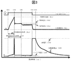
- FIG. 3 shows the behavior of the drive current (301) and the drive voltage (302) when the fuel injection valve is driven. From the top of the figure, the pulse signal (114), the drive current (301), and the drive voltage (302), which are drive commands for the fuel injection valve It has become.
- the drive voltage (302) describes the voltage generated between the downstream side fuel injection valve drive means (107) and the fuel injection valve control device (201) in FIG.
- the drive IC (105) drives the fuel injection valve (108) based on the pulse signal. Specifically, the drive of the fuel injection valve (108) is started from the time when the pulse signal is turned from OFF to ON (T303), the drive IC (105) is a fuel injection valve drive waveform command block ( Based on the drive current profile (115) determined in 102c), the current of the fuel injection valve (108) is controlled.
- FIG. 3 shows an example of current control.
- the high voltage (109) is reached until the drive current (301) reaches the target valve opening current (301a) which is the first control target value (T304).
- Supply Alternatively, as a control target at the time of valve opening, a high voltage (109) is supplied to the fuel injection valve (108) for a predetermined period (301e) from the time (T303) when the pulse signal (114) is turned ON. Supply.
- the control target value of the drive current (301) shifts to the holding current 1 (301b).
- the power supply voltage is switched to the battery voltage (110) that is the power supply voltage for holding the valve open, and then is switched to the holding current 2 (301c) that is the second target value of the holding current as necessary.
- the switching of the holding current is set as a predetermined period (301d) based on the characteristics of the fuel injection valve (108) from the time (T303) when the pulse signal (114) is turned on, for example.
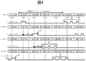
- FIG. 4 shows a pulse signal (114) when switching from single injection to multi-stage injection, which is the conventional injection control, and T401 in the figure shows a point in time when multi-stage injection control is permitted. .
- a control reference position (T408a to T408d) for each cylinder is provided as a general method of so-called angle control that performs architecture driving based on a predetermined crank angle.
- the timing of the architecture operation is measured at a desired angle with respect to the position (T408a to T408d).
- FIG. 4 will be described.
- T401 left side of T401 in the figure
- multi-stage injection control is prohibited, and normal one-time injection is executed (402, 403).
- the injection execution signal (404) which is the future (right side from T401 in the figure) with respect to T401 is on the left side with respect to T401, and the injection control is performed according to the injection timing (409) at this time. This is also a single injection.
- multi-stage injection it is defined that at least one fuel injection is performed during one combustion cycle.
- position (angle) differs for each cylinder from this one combustion cycle, 4 It is set to 720 deg between the combustion strokes (intake, compression, expansion, exhaust) of the cycle internal combustion engine.
- FIG. 5 is an enlarged view of, for example, 405a, 405b, and 405c in FIG. 4, from above, a pulse signal (501) to the fuel injection valve rod (108), a drive current (502), a high voltage (503) Drive voltage (504).
- the driving voltage (504) in this figure indicates the operating pressures on the upstream side and the downstream side of the fuel injection valve (108) as shown in FIG.
- multistage injection control of three injections is executed, and the pulse signal (114c) executes fuel injection of 405a, 405b, and 405c, respectively.
- the injection start timing is set to T505, T511, and T512 as the operation start timing of the fuel injection valve (108).
- the drive current has a drive current profile in which, after reaching the valve opening current (502a) (T506), the current supply to the fuel injection valve (108) is temporarily stopped until T507, and the drive current is supplied again from T507.
- the drive current (502) stops supplying to the fuel injection valve, and the same drive sequence is started from the next injection start timing (T511 or T512). Current supply.
- the high voltage (503) is normally in a state of being boosted to the high voltage set value (503a), and the fuel injection valve (108) is started to open (T505).
- the driver IC (105) issues a boost command to the high voltage generation means (104), and again after a certain boost period (T510). It becomes the high voltage set value (503a). Thereafter, the same operation is performed from the start of the next injection operation (T511).
- the drive voltage (504) is the time when the first fuel injection valve (108) is driven (405a) (T505), when a high voltage is supplied and the drive current (502) reaches the valve opening current (502a) ( The high voltage (503) is maintained until T506), but as described above, this is continued with a slight voltage drop.
- the behavior of the drive voltage (504) from the time (T508) when the pulse signal (114c) is turned off to T509 is omitted for the above description.
- the above operation is continued for the number of times specified by the multi-stage injection control.
- the behavior of the drive current (502) and the drive voltage (504) is the same, and thus the description thereof is omitted.
- FIG. 6 the abnormal state during multistage injection control will be described with reference to FIGS. 6, 7, 8, and 9.
- FIG. 6 shows the behavior of the drive current (502) and the drive voltage (503) when performing the three-stage injection as in FIG.
- the pulse signal (501) issues a three-stage injection command to the fuel injection valve (108) with T605, T607, and T608 as the injection start timing as in FIG.
- each injection start timing interval is narrower than that in FIG.
- the high voltage (603) is the high voltage set value (604a) at the first stage injection start timing (T605)
- the current (602a) is reached at T606, and since the pulse signal (601) is turned off at the time T606, the application of the drive current (602) is also stopped.
- the fuel injection valve (108) is also stopped.
- the driving voltage (604) behavior of the first stage is used from the high voltage set value (604a) to the time (T606) when the valve opening current (602a) is reached, so that a voltage drop occurs. Thereafter, the high voltage (603) performs the above-described boosting operation until a predetermined period (T609 in the figure) and tries to return to the high voltage set value (604a), but the second stage injection start timing (T607) If this occurs during this boosting operation, the high voltage is reused from the state where the high voltage set value (604a) is not reached.Therefore, the locus of the drive current (602) indicated by the broken line 602b is originally used. As shown by 602c, since the pulse signal (601) is turned OFF before reaching the valve opening current, a desired valve opening force cannot be obtained, and the current (602f) that does not satisfy the valve opening current (602a). ) Only.
- the high voltage at the time of the third stage injection start timing (T609) is lower than the second stage injection start timing (T607). ), And as a result, the actual drive current has a locus like 602e with respect to the normal drive current 602d, and the valve opening force may be further reduced.
- Fig. 7 shows this as the valve behavior of the fuel injection valve (108).
- the pulse signal (601) and the drive current (602) in FIG. 7 are the same as those in FIG.
- the valve body behavior (701) starts the valve opening operation with a slight delay time from the time (T605) when the pulse signal (601) is turned on (T702). This is because the drive current (602) is applied to the fuel injection valve (108), and it takes time until an electromotive force that can open the valve body is generated.
- the pulse signal (601) is turned off at T606, but the valve body behavior (701) is maintained in the valve open state by the residual magnetic force in the fuel injection valve (108), and thus the valve closing operation is performed. Takes time. For this reason, the timing at which the valve body completes closing is T703, and the on-off valve response of the valve body behavior (701) has a characteristic of being delayed with respect to the ON / OFF operation of the pulse signal (601).
- the valve body behavior (601) has no problem with the valve behavior of the stage injection. If the drive current (602) does not reach the valve opening current (602a), which is the control target, while the desired operation (601a) is performed, the amount of movement of the valve body (hereinafter referred to as lift amount) as in 601b and 601c. ) Is insufficient, the valve opening start timing (706) may vary, and the actual valve closing timing (T704) may vary with respect to the desired valve closing timing (T705). is there.
- such a state is determined to be normal or abnormal by the effective injection number determination means (102e), and the fuel injection command value is, for example, three-stage injection by the multi-stage injection normal control determination means (102d). Nevertheless, it is characterized by detecting the result that normal fuel injection has been performed only once.
- the multistage injection normal control determination means (102d) is implemented as a control program executed in the microcomputer (102), but is not limited to this implementation method.
- it may be mounted as a hardware circuit in the drive IC (105).
- FIG. 8 shows the pulse signal (801), drive current (802), and valve body behavior (802, 803) from the top.
- the pulse signal changes from OFF to ON (T804), and in accordance with this, application of the drive current starts.
- the application of the drive current (802) continues, and then the application of the drive current (802) is stopped when the pulse signal (802) is OFF (T807), Eventually, the residual current in the fuel injection valve (108) is released at T808, so that it becomes OA. Thereafter, the pulse signal (801) is turned on at T810 to instruct execution of the second-stage injection, and the drive current (802) is applied again. Thereafter, the drive current (802) is applied to the fuel injection valve (108) until the pulse signal is turned OFF (T813), and the application of the drive current is stopped as described above.
- the ON-OFF of the pulse signal (801) causes a valve opening response delay, which is compared to the OFF-ON operation.
- the response delay in the valve opening and closing has different characteristics for each fuel injection valve (108) due to individual variations and deterioration over time. It is common to have.
- the valve body behavior of the fuel injection valve A is represented by a solid line 802 and the valve body behavior of the fuel injection valve B is represented by a broken line 803, the valve of the fuel injection valve A with respect to the first stage injection start timing T804 will be described.
- the body response (802) starts the valve opening operation first (T805), and then the valve behavior (803) of the fuel injection valve B starts the valve opening operation at the timing of T806. Further, since the variation in the lift amount also exists in the fuel injection valve (108), the difference between 802 and 803 also occurs.
- valve body behavior (802, 803) starts the valve closing operation from the time (T807) when the pulse signal (801) is turned OFF, but the valve body behavior (803) of the fuel injection valve B is quickly closed.
- valve behavior (802) of the fuel injection valve A is a gradual valve closing operation.
- the pulse signal (801) is turned ON at T810 to perform the second stage injection operation, but the valve body behavior (803) of the fuel injection valve B shows the same behavior as the first stage, according to the command value.
- the valve closing behavior (802) of the fuel injection valve A is gradual, the second stage valve opening operation must be performed before completing the valve closing operation.
- Start (T811). After that, when the pulse signal (801) is turned off at T813, the valve behavior of both valve bodies (802, 803) will be closed according to their response characteristics.
- the timing is T814, and the closing timing of the fuel injection valve A is T815.
- the present invention makes a normal determination or an abnormality determination by the effective injection number determination means (102e), and the multi-stage injection normal control determination means (102d) sets the fuel injection command value to the two-stage injection. As a result, it can be detected that the fuel injection valve A can perform normal fuel injection only once.
- the total fuel injection amount in one combustion cycle largely deviates. Further, the sprays of the respective injections to be divided are connected, so that the reach of the spray in the cylinder (penetration) is extended, and the fuel adheres to the wall surface of the combustion chamber and the crown surface of the piston, causing an increase in soot discharge. End up.
- the characteristics change due to an increase in mechanical friction of a specific fuel injection valve, and even if a drive current equivalent to that of other fuel injection valves is applied.
- the command in which the energy necessary for opening the valve cannot be obtained and the pulse signal period is short there may be an abnormality that does not lead to actual injection.
- the fuel injection valve whose characteristics have changed the fuel is injected only a smaller number of times than the fuel injection command value, so that the fuel injection amount greatly deviates and the exhaust performance deteriorates.
- the present invention by determining such an abnormality in consideration of the behavior of the actual fuel injection valve, it is possible to appropriately perform control for suppressing deterioration of exhaust performance or to notify the driver of an abnormal state. It becomes.
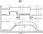
- the pulse signal (901) is turned ON at T907, and a drive current (not shown) is applied to the fuel injection valve (108).
- the drive voltage (902) behaves as described above, but the valve element in the fuel injection valve rod (108) is originally in the full lift position (904) according to the length of the ON period of the pulse signal (201).
- the valve closing operation may be performed without reaching the position (904).
- 905 in the figure shows the valve body behavior that is normal operation, when the control target of the drive current (not shown) has shifted to the holding current (T908), in order to maintain the holding current, The duty operation is performed until the time (T909) when the pulse signal (901) is turned off.
- Information on whether or not the duty operation of the drive voltage (902) is being performed is information that appears superimposed on the output from the fuel injection valve drive means (Hi) (106) to the fuel injection valve (108). According to the information, it is possible to grasp the operating state of the fuel injection valve (108) without requiring an additional sensor or the like and with less error due to disturbance.
- the predetermined period can be appropriately set as a period (for example, T303 to T304) in which the drive current should originally reach the holding current.
- the above-described determination method is merely an example. For example, there is a method of determining when the current operation deviates by a predetermined amount or more from a past normal operation due to learning or the like. Specifically, the valve closing completion timing of 905, which is normal valve body behavior, is T911, whereas the valve closing completion timing of 906, which is abnormal valve body behavior, is T910. A predetermined criterion may be provided, and if a deviation greater than this criterion occurs, the injection operation may be determined to be abnormal.
- the process proceeds to S1004, where multi-stage injection normality determination is performed. This determination method will also be described later. Thereafter, the process proceeds to S1005, and multi-stage injection normality determination is performed. If it is determined to be normal, the multi-stage injection is continued. If it is determined to be abnormal, the process proceeds to S1006 and a fail-safe process is performed as necessary. As an example of the fail-safe process, multi-stage injection is prohibited and the conventional one-time injection is used, and if necessary, notification to the driver (MIL lighting) is given. Further, a fail-safe process is also possible in which the total injection amount in one combustion cycle is adjusted to a desired amount by correcting the injection amount of each divided injection by the number of shifted injections while continuing the multi-stage injection.
- MIL lighting notification to the driver
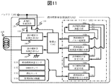
- S1003 in FIG. 10 will be described in detail. Since the configuration of FIG. 11 is basically the same as that of FIG. 1, detailed description of the overlapping configuration is omitted.
- S1003 in FIG. 10 based on the operating state of the fuel injection valve (108), parameters with physical changes are input, and signal processing or the like is performed as necessary. In this regard, one example is shown using the drive voltage of the fuel injection valve (108) with reference to FIG. 1, but other parameters include those described in FIG.
- the operation of the fuel injection valve (108) causes the fuel injection valve (108) to be distorted in a predetermined direction.
- a strain sensor (1101) is attached to the fuel injection valve (108), and this is A / D-input. Accordingly, it is necessary to perform frequency separation or the like.
- a KNOCK sensor (1102) can be used, but in this case, it is necessary to remove the seating noise of intake valves and exhaust valves provided in the KNOCK and the internal combustion engine. The process of setting the measurement period and removing the seating noise needs to be more complicated when performing multi-stage injection control.
- the fuel pressure sensor (1103) that measures the pressure of the fuel supplied to the fuel injection valve (108) is used. Is also possible.
- Information output from such an on-off valve detection function (1104) is information that appears superimposed on the output from the fuel injection valve drive means (Hi) (106) to the fuel injection valve (108), and changes in fuel pressure Is more responsive and accurate than capturing
- the execution injection number determination means (102e) it is more accurate to perform the determination by the execution injection number determination means (102e) based on the information appearing superimposed on the output to the fuel injection valve (108).
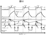
- FIG. 12 assumes the configuration of FIG. 1, and the information (116) output from the fuel injection valve drive state input means (102f) is the drive voltage (1203) of the fuel injection valve (108). Assuming
- the pulse signal (1201) in the figure is a three-stage injection command, and is turned on at T1206a, T1206b, and T1206c, and turned off at T1207a, T1207b, and T1207c.
- the drive current (1202) is applied to the fuel injection valve (108), and the drive voltage (1203) shows the behavior shown in the figure.
- the operation of the fuel injection valve (108) is monitored based on whether or not the normal determination value (1205a) is not less than a predetermined value.
- the value of 1209 is shown, which is equal to or greater than the normal determination value (1205a), and thus this injection operation is determined to be normal.
- the drive voltage (1203) is 1210 and 1211, respectively, and is not higher than the normal determination value (1205a), so it is determined that the injection operation is abnormal.
- the fuel injection valve (108) may not operate for some reason even though the multi-stage injection command value calculated by the microcomputer (102) is three-stage injection. It is also effective in the present invention to make abnormal when the drive voltage (1203) does not change from around 0 V at T1208a after a predetermined time has elapsed from the time when the pulse signal is turned on (T1206a).
- the drive voltage (1203) in this figure is expressed in operating pressure as described above, and the abnormality determination value (1205b) is also provided in the reverse direction so that the drive voltage (1203) at the time of abnormality determination is You may determine with the case where it is between a forward direction and a reverse direction as abnormality.
- the drive voltage (1203) is provided on the upstream side (106) and the downstream side (107) with respect to the fuel injection valve (108). Therefore, like the drive voltage (302) shown in FIG. 3, it is possible to input the drive voltage by setting either contact and GND, so the abnormality judgment value or normal judgment value is Not as long.
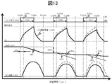
- the pulse signal (1301) is turned on at T1305a, T1305b, and T1305c and turned off at T1306a, T1306b, and T1306c, and the drive current (1302) is applied to the fuel injection valve (108) according to this command.
- the execution injection number determination means (102e) of the present invention stores at least the fuel pressure (1303) before the start of the first injection (T1305a), and the fuel pressure (1303) at the start of the next injection (T1305b). Whether or not the operation of the fuel injection valve is abnormal is determined based on whether or not the difference (1303d) with respect to () is a predetermined difference.
- This judgment value may be set based on the fuel pressure (1303) and the pulse signal (1301), or a predetermined calculation is performed based on the ON time (1301a, 1301b, 1301c) of the pulse signal (1301).
- the predicted slope (1303b) may be calculated, and it may be determined that a certain range is normal with respect to the calculated value.
- the fuel pressure (1303) has a characteristic that changes based on the valve body behavior (1304). This is due to the above-described valve opening / closing valve response, and fuel is injected from a certain amount or more of the lift amount of the valve body, so from the ON timing (T1305a, T1305b, T1305c) of the pulse signal (1301), The fuel pressure begins to fall after a certain delay (T1307a).
- this characteristic is based on the fuel pressure (1303) and the delay amount (1303a) increases, based on the fuel pressure, the delay amount (1303a) and the slope (1303b) of the fuel pressure drop obtained in the above explanation are obtained.
- the signal (1301) is turned off (T1306a, T1306b, T1306c)
- the first-stage injection is determined to be normal even if any of the determination methods described above is used, but the second-stage and third-stage injection operations are determined to be abnormal. To do.
- the behavior of the pulse signal (1401) and drive current (1402) in FIG. 14 is omitted for the above description.
- the valve body behavior is as described with reference to FIG. 8.
- the valve body behavior of the fuel injection valve A is 1404, and the valve body behavior of the fuel injection valve B is 1403.
- the on-off valve detection function (1104) includes (1) a method for detecting the valve opening start timing (T1408, T1409) and (2) the valve opening completion timing (T912 in FIG. 9) for the valve body provided in the fuel injection valve (108). ) And (3) a method of detecting the valve closing completion timing (T1415, T1416), etc., and any of them can be used to obtain the effects of the present invention.
- T1408, T1409 the valve opening start timing
- T912 in FIG. 9 for the valve body provided in the fuel injection valve (108).
- a method of detecting the valve closing completion timing T1415, T1416), etc.
- the valve body behavior (1403) of the fuel injection valve B operates normally in response to the command of the pulse signal (1401) as described with reference to FIG.
- the first stage injection operation can detect the valve opening start timing at T1409, and the valve closing completion timing can also be detected at T1411.
- the valve opening start timing can be detected at T1413, and the valve closing completion timing can be detected at T1415.
- the effective injection number determination means (102e) of the present invention can detect this within a predetermined range (for example, within a predetermined period from ON and OFF of the pulse signal (1401)), the valve opening detection and the valve closing detection are paired.
- the operation of the fuel injection valve (108) is determined to be normal.
- the valve body behavior (1403) of the fuel injection valve A shifts to the valve opening operation again without completing the valve closing operation because the valve closing response is slow.
- the start timing can be detected at T1408, and the second stage valve closing completion timing can be detected at T1416, but the first stage closing timing and the second stage opening timing should be detected. I can't.
- the effective injection number determination means (102e) of the present invention It is determined that there is an abnormality in injection, including that there is an abnormality in timing.
- the above determination method is possible only by (3) above, and it is determined as abnormal if the valve closing cannot be detected within a predetermined period from the OFF timing (T1410, T1416) of the pulse signal (1401). It is also possible.
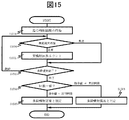
- the number of multistage injections of the cylinder is acquired. This is information (119) input by the multistage injection control calculation means (S102a) including the processing of S1001 in FIG.
- S1004 If it is determined in S1004 that there is an abnormality, if nothing is determined and it is determined that the operation is normal, the process proceeds to S1502, and the number of normal operations is counted. Thereafter, the process proceeds to S1503, based on the number of multistage injection commands acquired in S1501, it is determined how many injections are currently being performed, and if it is determined that the injection operation is to be continued, the fuel injection valve for the next injection ( 108) Return to S1004 to monitor the operation.
- the process proceeds to S1504, the command value acquired in S1501 is compared with the value counted in S1502, and if they match, the process proceeds to S1505, and in this cylinder, the multi-stage injection control is performed. Is determined to have been executed normally, and if they do not match, the process proceeds to S1506, where it is determined that there is an abnormality in the multi-stage injection control in the current cylinder.
- the required injection amount of the cylinder is set as the total injection amount, and in S1004, the fuel injection amount for each time in the multi-stage injection control is calculated, and in S1502, the fuel injection amount is integrated. After that, in S1504, the total injection amount is compared with the integrated injection amount. If the integrated fuel injection amount is within the predetermined range, the process proceeds to S1505. If it exceeds the predetermined range, the process proceeds to S1506 and the total injection amount is If the difference between the cumulative injection quantity and the cumulative injection quantity is stored, the fuel injection quantity can be increased or decreased as the fail-safe process.
- control device of the present invention can monitor multi-stage injection control, can guarantee normal operation, and can immediately shift to fail-safe processing when an abnormality occurs.
- the injection start timing and end timing of each injection in the conventional batch injection and multistage injection, and the normality of the injection amount are determined by the fuel injection valve. The determination may be made in consideration of the actual behavior. Further, in multi-stage injection, it may be determined whether or not the injection interval of the multi-stage injection is appropriately secured, instead of determining whether the fuel injection is performed as many times as the fuel injection command value. Thereby, the exhaust_gas
- the abnormality on the drive circuit side and the abnormality on the fuel injection valve side can be determined separately, and the fail-safe process can be switched according to the abnormality content determined separately.
- detection of abnormalities on the known drive circuit side such as OFF sticking abnormality / ON sticking abnormality detection of a switch element built in the driving circuit, or a driving circuit described in JP 2013-36344 A
- This abnormality detection may also be performed to determine which of the drive circuit side and the fuel injection valve side is abnormal.
- processing such as fail-safe processing, control command correction processing from the microcomputer, notification to the driver of the vehicle, or storing a log in the memory of the control device may be switched and executed.
- Fuel injection valve control device 102 ... Microcomputer 105 ... Driving IC 108 ... Fuel injection valve
Abstract
Description
となっている。尚、駆動電圧(302)は、図1における下流側燃料噴射弁駆動手段(107)と燃料噴射弁制御装置(201)のGND間に生じる電圧を記載する。 FIG. 3 shows the behavior of the drive current (301) and the drive voltage (302) when the fuel injection valve is driven. From the top of the figure, the pulse signal (114), the drive current (301), and the drive voltage (302), which are drive commands for the fuel injection valve
It has become. Incidentally, the drive voltage (302) describes the voltage generated between the downstream side fuel injection valve drive means (107) and the fuel injection valve control device (201) in FIG.
その後、T507から、駆動電流(502)の制御目標は、開弁保持電流(502b)となり、駆動電圧(504)は、バッテリ電圧(504a)となり、駆動電流(502)が開弁保持電流(502b)に至った時点から、Duty制御を行う。このため、駆動電圧(504)は、ON-OFF動作をパルス信号(114c)がOFFとなるT508まで、繰り返し行う。 From the time point (T506) when the valve opening current (502a) is reached, the current supply to the fuel injection valve (108) is stopped on the drive current profile of this figure. The same operation as described when the pulse signal is turned OFF (from T306 to T307) is performed. (In this figure, since the operation pressure is described, the high voltage (503) in the reverse direction is displayed on the minus side.)
After that, from T507, the control target of the driving current (502) is the valve opening holding current (502b), the driving voltage (504) is the battery voltage (504a), and the driving current (502) is the valve opening holding current (502b). ) Duty control is performed from the point of time. Therefore, the drive voltage (504) repeats the ON-OFF operation until T508 when the pulse signal (114c) is turned off.
その後、パルス信号がOFFとなる時点(T813)まで、駆動電流(802)が燃料噴射弁(108)へ印加され、先の説明した通り、駆動電流の印加は停止する。 After that, during the period when the pulse signal is ON, the application of the drive current (802) continues, and then the application of the drive current (802) is stopped when the pulse signal (802) is OFF (T807), Eventually, the residual current in the fuel injection valve (108) is released at T808, so that it becomes OA. Thereafter, the pulse signal (801) is turned on at T810 to instruct execution of the second-stage injection, and the drive current (802) is applied again.
Thereafter, the drive current (802) is applied to the fuel injection valve (108) until the pulse signal is turned OFF (T813), and the application of the drive current is stopped as described above.
具体的には、正常な弁体挙動である905の閉弁完了タイミングは、T911となるのに対し、異常な弁体挙動である906の閉弁完了タイミングはT910となるため、T911に対して、所定のクライテリアを設け、このクライテリア以上の乖離が生じた場合、その噴射動作は異常と判定しても良い。 Note that the above-described determination method is merely an example. For example, there is a method of determining when the current operation deviates by a predetermined amount or more from a past normal operation due to learning or the like.
Specifically, the valve closing completion timing of 905, which is normal valve body behavior, is T911, whereas the valve closing completion timing of 906, which is abnormal valve body behavior, is T910. A predetermined criterion may be provided, and if a deviation greater than this criterion occurs, the injection operation may be determined to be abnormal.
フェイルセーフ処理の1例として、多段噴射を禁止し、従来の1回噴射とすることや、必要に応じて、運転者への告知対応(MIL点灯)などが挙げられる。また、多段噴射を継続しつつ、ずれた噴射回数分、個々の分割噴射の噴射量を補正することで、1燃焼サイクル中の総噴射量を所望の量に調整するフェールセーフ処理も考えられる。 Thereafter, the process proceeds to S1004, where multi-stage injection normality determination is performed. This determination method will also be described later. Thereafter, the process proceeds to S1005, and multi-stage injection normality determination is performed. If it is determined to be normal, the multi-stage injection is continued. If it is determined to be abnormal, the process proceeds to S1006 and a fail-safe process is performed as necessary.
As an example of the fail-safe process, multi-stage injection is prohibited and the conventional one-time injection is used, and if necessary, notification to the driver (MIL lighting) is given. Further, a fail-safe process is also possible in which the total injection amount in one combustion cycle is adjusted to a desired amount by correcting the injection amount of each divided injection by the number of shifted injections while continuing the multi-stage injection.
同様に2段目の噴射動作についても、開弁開始タイミングをT1413で検知し、閉弁完了タイミングをT1415にて検知することができる。 The valve body behavior (1403) of the fuel injection valve B operates normally in response to the command of the pulse signal (1401) as described with reference to FIG. When this is viewed from the on-off valve detection information, the first stage injection operation can detect the valve opening start timing at T1409, and the valve closing completion timing can also be detected at T1411.
Similarly, for the second stage injection operation, the valve opening start timing can be detected at T1413, and the valve closing completion timing can be detected at T1415.
102・・・マイコン
105・・・駆動IC
108・・・燃料噴射弁 101 ... Fuel injection
108 ... Fuel injection valve
Claims (17)
- 制御指令によって内燃機関に燃料を噴射させるための燃料噴射弁を制御する燃料噴射弁の制御装置において、
前記燃料噴射弁の動作状態によって変化が生じるパラメータに基づいて、前記燃料噴射弁が前記制御指令に対応した動作を行っているかどうかを判定することを特徴とする燃料噴射弁の制御装置。 In a control device for a fuel injection valve for controlling a fuel injection valve for injecting fuel into an internal combustion engine according to a control command,
A control device for a fuel injection valve, which determines whether or not the fuel injection valve is performing an operation corresponding to the control command based on a parameter that varies depending on an operation state of the fuel injection valve. - 請求項1記載の燃料噴射弁の制御装置において、
前記制御装置は、前記燃料噴射弁の制御に関するプログラムを実行する演算処理装置を備え、
前記燃料噴射弁の動作状態によって変化が生じるパラメータに基づく、前記燃料噴射弁が前記制御指令に対応した動作を行っているかどうかの判定は、前記演算処理装置によって実行されることを特徴とする燃料噴射弁の制御装置。 The control device for a fuel injection valve according to claim 1,
The control device includes an arithmetic processing device that executes a program related to control of the fuel injection valve,
Determination of whether or not the fuel injection valve is performing an operation corresponding to the control command based on a parameter that varies depending on an operation state of the fuel injection valve is executed by the arithmetic processing unit. Control device for injection valve. - 請求項2記載の燃料噴射弁の制御装置において、
前記燃料噴射弁の制御装置は、前記内燃機関の1燃焼サイクル中に複数回前記燃料噴射弁から燃料を噴射させ、
前記パラメータに基づいて、前記制御指令に対応した回数、前記燃料噴射弁が噴射を行っているかどうかを判定することを特徴とする燃料噴射弁の制御装置。 The control apparatus for a fuel injection valve according to claim 2,
The control device for the fuel injection valve injects fuel from the fuel injection valve a plurality of times during one combustion cycle of the internal combustion engine,
A control device for a fuel injection valve, wherein, based on the parameter, it is determined whether or not the fuel injection valve performs injection a number of times corresponding to the control command. - 請求項3に記載の燃料噴射弁の制御装置において、
前記パラメータに基づいて、前記制御指令に対応した噴射量、または噴射タイミングで前記燃料噴射弁が噴射を行っているかどうかを判定することを特徴とする燃料噴射弁の制御装置。 The control apparatus for a fuel injection valve according to claim 3,
A control device for a fuel injection valve, which determines whether or not the fuel injection valve is performing injection at an injection amount or an injection timing corresponding to the control command based on the parameter. - 請求項3に記載の燃料噴射弁の制御装置において、
前記パラメータは、前記燃料噴射弁の振動を検出する振動センサの出力値、前記燃料噴射弁の歪を検出する歪センサの出力値、前記燃料噴射弁に供給する燃料の圧力を検出する燃圧センサの出力値、前記燃料噴射弁の開弁時期、前記燃料噴射弁の閉弁時期のうち少なくとも一つであることを特徴とする燃料噴射弁の制御装置。 The control apparatus for a fuel injection valve according to claim 3,
The parameter includes an output value of a vibration sensor that detects vibration of the fuel injection valve, an output value of a strain sensor that detects distortion of the fuel injection valve, and a fuel pressure sensor that detects a pressure of fuel supplied to the fuel injection valve. The fuel injection valve control device is at least one of an output value, a valve opening timing of the fuel injection valve, and a valve closing timing of the fuel injection valve. - 請求項2に記載の燃料噴射弁の制御装置において、
前記制御装置は、前記燃料噴射弁への駆動電圧を出力するためのスイッチ素子を含む駆動回路を備え、前記パラメータは、前記駆動回路から前記燃料噴射弁への出力に重畳して現れる情報であることを特徴とする燃料噴射弁の制御装置。 The fuel injection valve control device according to claim 2,
The control device includes a drive circuit including a switch element for outputting a drive voltage to the fuel injection valve, and the parameter is information that appears superimposed on an output from the drive circuit to the fuel injection valve. A control device for a fuel injection valve. - 請求項6に記載の燃料噴射弁の制御装置において、
前記パラメータは、前記燃料噴射弁の駆動電流値または駆動電圧値の微小変化であることを特徴とする燃料噴射弁の制御装置。 The control device for a fuel injection valve according to claim 6,
The control device for a fuel injection valve, wherein the parameter is a minute change in a drive current value or a drive voltage value of the fuel injection valve. - 請求項3に記載の燃料噴射弁の制御装置において、
前記制御装置が1燃焼サイクル中に複数回噴射制御を行った際の、正常動作回数または異常動作回数の少なくとも一方を算出することを特徴とする燃料噴射弁の制御装置。 The control apparatus for a fuel injection valve according to claim 3,
A control device for a fuel injection valve, wherein the control device calculates at least one of the number of normal operations or the number of abnormal operations when injection control is performed a plurality of times during one combustion cycle. - 請求項8に記載の燃料噴射弁の制御装置において、
前記制御指令に基づく噴射回数と、前記正常動作回数または前記異常動作回数の少なくとも一方を比較し、
前記制御指令に基づく噴射回数と前記正常動作回数とが一致した場合、又は、前記制御指令に基づく多段噴射回数から前記異常動作回数を減算した値が前記制御指令に基づく噴射回数と等しい場合、噴射制御が正常実行されたと判定し、
前記制御指令に基づく噴射回数と前記正常動作回数とが不一致の場合、又は、前記制御指令に基づく噴射回数から前記異常動作回数を減算した値が前記制御指令に基づく噴射回数でない場合、前記噴射制御が異常実行されたと判定することを特徴とする燃料噴射弁の制御装置。 The control apparatus for a fuel injection valve according to claim 8,
Compare the number of injections based on the control command and at least one of the number of normal operations or the number of abnormal operations,
When the number of injections based on the control command matches the number of normal operations, or when the value obtained by subtracting the number of abnormal operations from the number of multi-stage injections based on the control command is equal to the number of injections based on the control command, Judge that the control was executed normally,
If the number of injections based on the control command does not match the number of normal operations, or if the value obtained by subtracting the number of abnormal operations from the number of injections based on the control command is not the number of injections based on the control command, the injection control It is determined that is abnormally executed, a control device for a fuel injection valve. - 請求項6に記載の燃料噴射弁の制御装置において、
前記制御装置は前記燃料噴射弁の駆動電流の計測値に基づき、前記駆動電流が所定の電流値となるように前記スイッチ素子をオン/オフ制御し、
前記パラメータは、前記制御指令による前記燃料噴射弁の駆動時間が所定時間以上のときの、前記スイッチ素子のオン動作またはオフ動作の少なくとも一方の有無であることを特徴とする燃料噴射弁の制御装置。 The control device for a fuel injection valve according to claim 6,
The control device performs on / off control of the switch element based on a measured value of the drive current of the fuel injection valve so that the drive current becomes a predetermined current value,
The control device for a fuel injection valve, wherein the parameter is the presence or absence of at least one of an ON operation and an OFF operation of the switch element when the drive time of the fuel injection valve according to the control command is a predetermined time or more . - 請求項3に記載の燃料噴射弁の制御装置において、
前記制御装置は、バッテリ電圧を昇圧して前記バッテリ電圧よりも高い高電圧を生成する高電圧生成回路を備え、前記パラメータは前記高電圧であり、前記制御指令による駆動開始直後に前記高電圧が供給されたときの、前記燃料噴射弁の駆動電圧が予め定められた高電圧電圧正常判定値以上であるか否かに基づいて、前記制御指令に対応した回数、前記燃料噴射弁が噴射を行っているかどうかを判定することを特徴とする燃料噴射弁の制御装置。 The control apparatus for a fuel injection valve according to claim 3,
The control device includes a high voltage generation circuit that boosts a battery voltage to generate a high voltage higher than the battery voltage, the parameter is the high voltage, and the high voltage is set immediately after the start of driving by the control command. The fuel injector performs injection a number of times corresponding to the control command based on whether or not the drive voltage of the fuel injector when supplied is equal to or higher than a predetermined high voltage normality determination value. It is determined whether or not the fuel injection valve control device. - 請求項3に記載の燃料噴射弁の制御装置において、
前記パラメータは前記燃料噴射弁へ供給する燃料の圧力であり、
1燃焼サイクル中初回噴射開始前の燃料圧力と、前記制御指令による前記燃料噴射弁の駆動期間と燃料圧力とから推定される燃圧降下と、に基づいて、前記制御指令に対応した回数、前記燃料噴射弁が噴射を行っているかどうかを判定することを特徴とする燃料噴射弁の制御装置。 The control apparatus for a fuel injection valve according to claim 3,
The parameter is a pressure of fuel supplied to the fuel injection valve,
The number of times corresponding to the control command based on the fuel pressure before the start of the first injection in one combustion cycle, and the fuel pressure drop estimated from the drive period of the fuel injection valve and the fuel pressure by the control command, A control device for a fuel injection valve, wherein it is determined whether or not the injection valve is injecting. - 請求項2に記載の燃料噴射弁の制御装置において、
前記パラメータは、前記燃料噴射弁の開弁開始時期、開弁完了時期、閉弁完了時期のうち少なくとも1つであることを特徴とする燃料噴射弁の制御装置。 The fuel injection valve control device according to claim 2,
The control device for a fuel injection valve, wherein the parameter is at least one of a valve opening start timing, a valve opening completion timing, and a valve closing completion timing of the fuel injection valve. - 請求項13に記載の燃料噴射弁の制御装置において、
前記開弁開始時期または前記開弁完了時期と、前記閉弁完了時期とが所定期間以内に検知された場合、燃料噴射弁の正常動作と判定し、所定期間を超えて検出された場合、前記燃料噴射弁が前記制御指令に対応した動作を行っていると判定することを特徴とする燃料噴射弁の制御装置。 The control apparatus for a fuel injection valve according to claim 13,
When the valve opening start timing or the valve opening completion timing and the valve closing completion timing are detected within a predetermined period, it is determined that the fuel injector is operating normally, and when it is detected over a predetermined period, It is determined that the fuel injection valve is performing an operation corresponding to the control command. - 請求項3に記載の燃料噴射弁の制御装置において、前記燃料噴射弁が前記制御指令に対応した動作を行っていないと判定した場合、分割多段噴射の禁止、車両の運転者への通知、ログの記憶、1燃焼サイクル中の燃料噴射量の補正、または燃料噴射時期の補正、の少なくとも1つを行うことを特徴とした燃料噴射弁の制御装置。 4. The control device for a fuel injection valve according to claim 3, wherein when it is determined that the fuel injection valve is not performing an operation corresponding to the control command, prohibition of divided multi-stage injection, notification to a vehicle driver, log The fuel injection valve control device performs at least one of storage, correction of the fuel injection amount during the combustion cycle, and correction of the fuel injection timing.
- 請求項2記載の燃料噴射弁の制御装置において、
前記演算処理装置は、前記燃料噴射弁への駆動電圧を出力するためのスイッチ素子を含む駆動回路を診断し、前記駆動回路の異常状態と、前記燃料噴射弁が前記制御指令に対応した動作を行っていない異常状態と、を区別して判定し、判定結果に応じてフェールセーフ処理、前記制御指令の補正処理、車両の運転者への通知、またはログの記憶のうち少なくとも一つを含む処理を切り替えることを特徴とする燃料噴射弁の制御装置。 The control apparatus for a fuel injection valve according to claim 2,
The arithmetic processing unit diagnoses a drive circuit including a switch element for outputting a drive voltage to the fuel injection valve, an abnormal state of the drive circuit, and an operation corresponding to the control command by the fuel injection valve. An abnormal state that is not performed is determined separately, and a process including at least one of fail-safe processing, correction processing for the control command, notification to the driver of the vehicle, or log storage according to the determination result A control device for a fuel injection valve, characterized by switching. - 内燃機関に燃料を噴射させるための燃料噴射弁の制御に関するプログラムを実行する演算処理装置を備え、
前記演算処理装置は、前記燃料噴射弁への駆動電圧を制御するためのスイッチ素子を含む駆動回路に対して制御指令を送信し、前記燃料噴射弁を制御する燃料噴射弁の制御装置において、
前記演算処理装置は、前記燃料噴射弁の動作状態によって変化が生じるパラメータに基づいて、前記燃料噴射弁が前記制御指令に対応した動作を行っているかどうかを判定することを特徴とする燃料噴射弁の制御装置。 An arithmetic processing unit that executes a program related to control of a fuel injection valve for injecting fuel into an internal combustion engine;
The arithmetic processing unit transmits a control command to a drive circuit including a switch element for controlling a drive voltage to the fuel injection valve, and controls the fuel injection valve.
The arithmetic processing unit determines whether the fuel injection valve is performing an operation corresponding to the control command based on a parameter that varies depending on an operation state of the fuel injection valve. Control device.
Priority Applications (4)
| Application Number | Priority Date | Filing Date | Title |
|---|---|---|---|
| EP16749046.5A EP3258092B1 (en) | 2015-02-09 | 2016-01-29 | Control device for fuel injection valve |
| JP2016574718A JPWO2016129402A1 (en) | 2015-02-09 | 2016-01-29 | Control device for fuel injection valve |
| CN201680004364.4A CN107110050B (en) | 2015-02-09 | 2016-01-29 | Control device for fuel injection valve |
| US15/540,310 US10309336B2 (en) | 2015-02-09 | 2016-01-29 | Control device for fuel injection valve |
Applications Claiming Priority (2)
| Application Number | Priority Date | Filing Date | Title |
|---|---|---|---|
| JP2015022787 | 2015-02-09 | ||
| JP2015-022787 | 2015-02-09 |
Publications (1)
| Publication Number | Publication Date |
|---|---|
| WO2016129402A1 true WO2016129402A1 (en) | 2016-08-18 |
Family
ID=56614305
Family Applications (1)
| Application Number | Title | Priority Date | Filing Date |
|---|---|---|---|
| PCT/JP2016/052566 WO2016129402A1 (en) | 2015-02-09 | 2016-01-29 | Control device for fuel injection valve |
Country Status (5)
| Country | Link |
|---|---|
| US (1) | US10309336B2 (en) |
| EP (1) | EP3258092B1 (en) |
| JP (2) | JPWO2016129402A1 (en) |
| CN (1) | CN107110050B (en) |
| WO (1) | WO2016129402A1 (en) |
Cited By (4)
| Publication number | Priority date | Publication date | Assignee | Title |
|---|---|---|---|---|
| JP2019196761A (en) * | 2018-05-11 | 2019-11-14 | 本田技研工業株式会社 | Fuel injection control device |
| JP2021042699A (en) * | 2019-09-10 | 2021-03-18 | 株式会社デンソー | Injection control device |
| US11885275B2 (en) | 2020-06-23 | 2024-01-30 | Hitachi Astemo, Ltd. | Fuel injection control device |
| JP7446944B2 (en) | 2020-08-19 | 2024-03-11 | 日立Astemo株式会社 | Fuel injection valve control device |
Families Citing this family (10)
| Publication number | Priority date | Publication date | Assignee | Title |
|---|---|---|---|---|
| JP6642403B2 (en) * | 2016-12-13 | 2020-02-05 | 株式会社デンソー | Fuel injection control device |
| JP6555287B2 (en) * | 2017-03-03 | 2019-08-07 | トヨタ自動車株式会社 | Fuel injection control device for internal combustion engine |
| US10393056B2 (en) * | 2017-05-10 | 2019-08-27 | Ford Global Technologies, Llc | Method and system for characterizing a port fuel injector |
| GB2573522B (en) * | 2018-05-08 | 2020-08-19 | Delphi Tech Ip Ltd | Method of identifying faults in the operation of hydraulic fuel injectors having accelerometers |
| JP7304856B2 (en) * | 2018-07-03 | 2023-07-07 | 日立Astemo株式会社 | load drive circuit, load drive system |
| JP7186029B2 (en) * | 2018-07-11 | 2022-12-08 | 日立Astemo株式会社 | CONTROL DEVICE AND DIAGNOSIS METHOD FOR INTERNAL COMBUSTION ENGINE |
| JP6956270B2 (en) * | 2018-07-20 | 2021-11-02 | 日立Astemo株式会社 | Fuel injection control device |
| CN113167186B (en) * | 2018-11-30 | 2023-03-24 | 日立安斯泰莫株式会社 | Load driving device and control method of fuel injection device |
| KR20210019223A (en) * | 2019-08-12 | 2021-02-22 | 현대자동차주식회사 | Method and device for learning opening time of injector for vehicle engine |
| CN113482824B (en) * | 2021-07-28 | 2022-06-28 | 潍柴动力股份有限公司 | Detection method and device for oil sprayer |
Citations (9)
| Publication number | Priority date | Publication date | Assignee | Title |
|---|---|---|---|---|
| JPS62153564A (en) * | 1985-12-26 | 1987-07-08 | Nippon Denso Co Ltd | Device for detecting abnormality in engine |
| JPS6312878A (en) * | 1986-07-02 | 1988-01-20 | Yamaha Motor Co Ltd | Operation detector for fuel injection valve in internal combustion engine |
| JPH0317173U (en) * | 1989-06-29 | 1991-02-20 | ||
| JPH084577A (en) * | 1994-06-20 | 1996-01-09 | Toyota Motor Corp | Fuel injection device for internal combustion engine |
| JPH10318027A (en) * | 1997-05-15 | 1998-12-02 | Nippon Soken Inc | Fuel injection valve abnormality detecting device for internal combustion engine |
| JP2005330945A (en) * | 2004-05-21 | 2005-12-02 | Denso Corp | Fuel injection device |
| JP2007138851A (en) * | 2005-11-18 | 2007-06-07 | Denso Corp | Method for diagnosing abnormality of solenoid control valve |
| JP2013204442A (en) * | 2012-03-27 | 2013-10-07 | Denso Corp | Injector drive device |
| JP2014031790A (en) * | 2012-07-09 | 2014-02-20 | Honda Motor Co Ltd | Fuel injection control device of internal combustion engine |
Family Cites Families (19)
| Publication number | Priority date | Publication date | Assignee | Title |
|---|---|---|---|---|
| US5535621A (en) * | 1994-03-02 | 1996-07-16 | Ford Motor Company | On-board detection of fuel injector malfunction |
| US5492099A (en) * | 1995-01-06 | 1996-02-20 | Caterpillar Inc. | Cylinder fault detection using rail pressure signal |
| JP3296529B2 (en) | 1995-02-14 | 2002-07-02 | 株式会社デンソー | Fuel injection device |
| JP4211044B2 (en) | 2000-03-22 | 2009-01-21 | 株式会社デンソー | Fuel injection device |
| DE60018549T2 (en) * | 2000-04-01 | 2006-04-20 | Robert Bosch Gmbh | fuel injection system |
| DE102004006896A1 (en) * | 2004-02-12 | 2005-09-15 | Mtu Friedrichshafen Gmbh | Method for control and regulation of an IC engine with common-rail system uses calculation of injection end and injection begin deviations to evaluate fuel injectors |
| JP4470772B2 (en) * | 2005-03-18 | 2010-06-02 | トヨタ自動車株式会社 | Internal combustion engine state determination device |
| JP2008144723A (en) * | 2006-12-13 | 2008-06-26 | Toyota Motor Corp | Control device for internal combustion engine |
| JP2009150246A (en) * | 2007-12-19 | 2009-07-09 | Denso Corp | Fuel injector malfunction detecting apparatus and detecting method therefor |
| JP4656198B2 (en) * | 2008-07-15 | 2011-03-23 | 株式会社デンソー | Fuel injection control device |
| US8737034B2 (en) * | 2010-01-13 | 2014-05-27 | Infineon Technologies Ag | Determining a change in the activation state of an electromagnetic actuator |
| JP5198496B2 (en) * | 2010-03-09 | 2013-05-15 | 日立オートモティブシステムズ株式会社 | Engine control unit for internal combustion engines |
| JP2012021428A (en) | 2010-07-13 | 2012-02-02 | Denso Corp | Emission deterioration informing device |
| JP5594251B2 (en) * | 2011-08-03 | 2014-09-24 | 株式会社デンソー | Fuel injection control device and fuel injection control system |
| DE102011083033A1 (en) | 2011-09-20 | 2013-03-21 | Robert Bosch Gmbh | Method for assessing an injection behavior of at least one injection valve of an internal combustion engine and operating method for internal combustion engine |
| WO2013191267A1 (en) * | 2012-06-21 | 2013-12-27 | 日立オートモティブシステムズ株式会社 | Control device for internal combustion engine |
| JP5975899B2 (en) | 2013-02-08 | 2016-08-23 | 日立オートモティブシステムズ株式会社 | Drive device for fuel injection device |
| JP2014159772A (en) * | 2013-02-20 | 2014-09-04 | Hitachi Automotive Systems Ltd | Control device for internal combustion engine |
| WO2015015541A1 (en) | 2013-07-29 | 2015-02-05 | 日立オートモティブシステムズ株式会社 | Drive device for fuel injection device, and fuel injection system |
-
2016
- 2016-01-29 CN CN201680004364.4A patent/CN107110050B/en active Active
- 2016-01-29 EP EP16749046.5A patent/EP3258092B1/en active Active
- 2016-01-29 JP JP2016574718A patent/JPWO2016129402A1/en active Pending
- 2016-01-29 WO PCT/JP2016/052566 patent/WO2016129402A1/en active Application Filing
- 2016-01-29 US US15/540,310 patent/US10309336B2/en active Active
-
2019
- 2019-05-30 JP JP2019100877A patent/JP7125916B2/en active Active
Patent Citations (9)
| Publication number | Priority date | Publication date | Assignee | Title |
|---|---|---|---|---|
| JPS62153564A (en) * | 1985-12-26 | 1987-07-08 | Nippon Denso Co Ltd | Device for detecting abnormality in engine |
| JPS6312878A (en) * | 1986-07-02 | 1988-01-20 | Yamaha Motor Co Ltd | Operation detector for fuel injection valve in internal combustion engine |
| JPH0317173U (en) * | 1989-06-29 | 1991-02-20 | ||
| JPH084577A (en) * | 1994-06-20 | 1996-01-09 | Toyota Motor Corp | Fuel injection device for internal combustion engine |
| JPH10318027A (en) * | 1997-05-15 | 1998-12-02 | Nippon Soken Inc | Fuel injection valve abnormality detecting device for internal combustion engine |
| JP2005330945A (en) * | 2004-05-21 | 2005-12-02 | Denso Corp | Fuel injection device |
| JP2007138851A (en) * | 2005-11-18 | 2007-06-07 | Denso Corp | Method for diagnosing abnormality of solenoid control valve |
| JP2013204442A (en) * | 2012-03-27 | 2013-10-07 | Denso Corp | Injector drive device |
| JP2014031790A (en) * | 2012-07-09 | 2014-02-20 | Honda Motor Co Ltd | Fuel injection control device of internal combustion engine |
Non-Patent Citations (1)
| Title |
|---|
| See also references of EP3258092A4 * |
Cited By (5)
| Publication number | Priority date | Publication date | Assignee | Title |
|---|---|---|---|---|
| JP2019196761A (en) * | 2018-05-11 | 2019-11-14 | 本田技研工業株式会社 | Fuel injection control device |
| JP2021042699A (en) * | 2019-09-10 | 2021-03-18 | 株式会社デンソー | Injection control device |
| JP7255432B2 (en) | 2019-09-10 | 2023-04-11 | 株式会社デンソー | Injection control device |
| US11885275B2 (en) | 2020-06-23 | 2024-01-30 | Hitachi Astemo, Ltd. | Fuel injection control device |
| JP7446944B2 (en) | 2020-08-19 | 2024-03-11 | 日立Astemo株式会社 | Fuel injection valve control device |
Also Published As
| Publication number | Publication date |
|---|---|
| EP3258092A1 (en) | 2017-12-20 |
| CN107110050A (en) | 2017-08-29 |
| US10309336B2 (en) | 2019-06-04 |
| EP3258092B1 (en) | 2020-05-13 |
| JP7125916B2 (en) | 2022-08-25 |
| JP2019163765A (en) | 2019-09-26 |
| JPWO2016129402A1 (en) | 2017-09-28 |
| EP3258092A4 (en) | 2018-09-26 |
| CN107110050B (en) | 2020-05-19 |
| US20180010545A1 (en) | 2018-01-11 |
Similar Documents
| Publication | Publication Date | Title |
|---|---|---|
| WO2016129402A1 (en) | Control device for fuel injection valve | |
| US11193442B2 (en) | Fuel injection control device | |
| CN104632445B (en) | Method for detecting a fault in the opening behavior of an injector | |
| US10865727B2 (en) | Device for controlling at least one switchable valve | |
| US10393051B2 (en) | Internal-combustion-engine fuel injection control device | |
| CZ110399A3 (en) | Process and apparatus for charging and discharging piezoelectric element | |
| US9556814B2 (en) | Method for controlling pressure in a high-pressure region of an internal combustion engine | |
| US9945338B2 (en) | Method for operating a fuel injection system with pressure reduction, and a fuel injection system comprising a fuel injection valve with a servo valve | |
| WO2017191732A1 (en) | Fuel injection control device | |
| EP2146080A1 (en) | Indication of solenoid temperature change | |
| JP5924238B2 (en) | Injection delay detection device | |
| JP2007534883A (en) | Operation circuit diagnostic method | |
| KR20190082292A (en) | How to control solenoid valve of fuel injector | |
| US20170074197A1 (en) | Method for determining the closing characteristic of the control valve of a piezo servo injector | |
| JP2013002475A (en) | Solenoid valve driving apparatus | |
| CN115075938A (en) | Self-learning control method and device for turbocharger, vehicle and storage medium | |
| KR20180006333A (en) | Method and control unit for the functional testing of a gas metering valve | |
| JP7446944B2 (en) | Fuel injection valve control device | |
| KR20170007292A (en) | Method for determining a closing time of a fuel injector | |
| WO2018110241A1 (en) | Fuel injection control device | |
| JP7459834B2 (en) | Fuel injection control device for internal combustion engine | |
| JP2018145804A (en) | Electronic control device | |
| JP4629278B2 (en) | Operation control method for accumulator fuel injector | |
| JP2019039323A (en) | Fuel injection control device | |
| JP4863528B2 (en) | Operation control method for accumulator fuel injector |
Legal Events
| Date | Code | Title | Description |
|---|---|---|---|
| 121 | Ep: the epo has been informed by wipo that ep was designated in this application |
Ref document number: 16749046 Country of ref document: EP Kind code of ref document: A1 |
|
| ENP | Entry into the national phase |
Ref document number: 2016574718 Country of ref document: JP Kind code of ref document: A |
|
| REEP | Request for entry into the european phase |
Ref document number: 2016749046 Country of ref document: EP |
|
| WWE | Wipo information: entry into national phase |
Ref document number: 15540310 Country of ref document: US |
|
| NENP | Non-entry into the national phase |
Ref country code: DE |