WO2016129088A1 - 送信装置、受信装置、および送受信システム - Google Patents
送信装置、受信装置、および送受信システム Download PDFInfo
- Publication number
- WO2016129088A1 WO2016129088A1 PCT/JP2015/053870 JP2015053870W WO2016129088A1 WO 2016129088 A1 WO2016129088 A1 WO 2016129088A1 JP 2015053870 W JP2015053870 W JP 2015053870W WO 2016129088 A1 WO2016129088 A1 WO 2016129088A1
- Authority
- WO
- WIPO (PCT)
- Prior art keywords
- unit
- data
- transmission
- bits
- parallel
- Prior art date
- Legal status (The legal status is an assumption and is not a legal conclusion. Google has not performed a legal analysis and makes no representation as to the accuracy of the status listed.)
- Ceased
Links
Images







Classifications
-
- G—PHYSICS
- G09—EDUCATION; CRYPTOGRAPHY; DISPLAY; ADVERTISING; SEALS
- G09G—ARRANGEMENTS OR CIRCUITS FOR CONTROL OF INDICATING DEVICES USING STATIC MEANS TO PRESENT VARIABLE INFORMATION
- G09G5/00—Control arrangements or circuits for visual indicators common to cathode-ray tube indicators and other visual indicators
-
- H—ELECTRICITY
- H04—ELECTRIC COMMUNICATION TECHNIQUE
- H04L—TRANSMISSION OF DIGITAL INFORMATION, e.g. TELEGRAPHIC COMMUNICATION
- H04L25/00—Baseband systems
- H04L25/38—Synchronous or start-stop systems, e.g. for Baudot code
- H04L25/40—Transmitting circuits; Receiving circuits
- H04L25/49—Transmitting circuits; Receiving circuits using code conversion at the transmitter; using predistortion; using insertion of idle bits for obtaining a desired frequency spectrum; using three or more amplitude levels ; Baseband coding techniques specific to data transmission systems
Definitions
- the present invention relates to a transmission device, a reception device, and a transmission / reception system, and more particularly to a technique effective in improving reliability in video transmission.
- HDMI High-Definition Multimedia Interface
- This HDMI (registered trademark) interface standard is disclosed in Non-Patent Document 1.
- Patent Document 1 states that “expansion beyond the maximum value in the current standards such as 15 Gbps and 20 Gbps is required in the future”, so “maintaining compatibility of connectors (plugs and receptacles)” On the other hand, it is described that “the current number of three data differential line pairs is increased to four or more. In accordance with this, the data rate is increased by the number of lanes for transmitting data”.
- a word separation means for separating N bits of digital data (N is a positive integer) into upper m bits (m is a positive integer, N> m) and lower (N ⁇ m) bits;
- Upper recording signal forming means for extracting a signal representing a value for each bit of the upper m bits
- lower recording signal forming means for extracting a signal representing a value for each bit of the lower (Nm) bits
- the amplitude of the signal of the upper bit is made larger than the amplitude of the signal of the lower bit and synthesized for each bit.
- a multi-valued signal synthesizing unit that multi-values the signal and transmits the multi-valued signal synthesized by the multi-valued signal synthesizing unit.
- JP 2012-85067 A Japanese Patent No. 3024132
- HDMI is required to transmit a large amount of data such as 4K / 8K at high speed.
- HDMI supports high-speed data transmission by increasing the frequency of the data transmission clock.
- increasing the frequency of the data transmission clock increases the high-frequency loss of the HDMI cable, which may impair the reliability of data transmission.
- An object of the present invention is to provide a technique capable of ensuring reliability in multi-level serial transmission of video data.
- a typical transmission apparatus includes a selector, a first scramble unit, a first encoding unit, a second scramble unit, a second encoding unit, and a multi-level output unit.
- the selector sorts the video data into an upper bit group and a lower bit group.
- the first scrambler scrambles the upper bit group assigned by the selector.
- the first encoding unit encodes the data scrambled by the first scramble unit.
- the second scrambler scrambles the lower bit group assigned by the selector.
- the second encoding unit encodes the data scrambled by the second scramble unit.
- the multi-level output unit multi-values each bit of the data encoded by the first encoding unit by assigning at least twice the weight of each bit of the data encoded by the second encoding unit. Serial output.
- the second encoding unit includes a cumulative disparity of the code data encoded by the first encoding unit, a cumulative disparity of the code data encoded by the second encoding unit, and the first encoding.
- the code data is determined and output from the disparity of the code data determined by the unit.
- the first encoding unit selects code data so that the absolute value of the accumulated disparity of the code data output from the first encoding unit is small
- the second encoding unit selects the first code.
- a code is added so that the absolute value of the total disparity is reduced by adding the cumulative disparity of the code data output by the second encoding unit to the numerical value obtained by multiplying the cumulative disparity output by the encoding unit by a value equal to the weight. Determine and output the data.
- a typical receiving apparatus includes a multi-value input unit, a first serial-parallel conversion unit, a first decoding unit, a first descrambling unit, a second serial-parallel conversion unit, a second decoding unit, There are two descrambling parts and a composite part.
- the multi-level input unit restores the multi-level data in which the received upper bits are added with a weight at least twice that of the lower bits to the upper bits and the lower bits.
- the first serial-parallel conversion unit parallelizes the upper bits restored by the multi-value input unit and converts them into parallel data.
- the first decoding unit decodes the parallel data parallelized by the first serial-parallel conversion unit.
- the first descrambling unit descrambles the data decoded by the first decoding unit.
- the second serial-parallel conversion unit parallelizes the lower bits restored by the multi-value input unit and converts them into parallel data.
- the second decoding unit decodes the parallel data parallelized by the second serial-parallel conversion unit.
- the second descrambling unit descrambles the data decoded by the second decoding unit.
- the composite unit generates video data from the descrambled data output from the first descrambling unit and the second descrambling unit.
- the encryption / decryption unit performs encryption / decryption of the video data generated by the composite unit.
- the composite unit composites the data scrambled by the first scramble release unit and the second scramble release unit, rearranges them into input units handled by the encryption / decryption unit, and outputs them.
- the receiving apparatus includes an error detection circuit that detects a transmission error of parallel data when the first decoding unit and the second decoding unit decode parallel data.
- the error detection circuit estimates parallel data input to the first decoding unit and the second decoding unit from the data decoded by the first decoding unit and the second decoding unit, respectively.
- the first serial-to-parallel conversion unit and the second serial-to-parallel conversion unit detect a transmission error from the difference from the parallel data respectively parallelized.
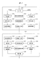
- FIG. 3 is an explanatory diagram illustrating an example of a configuration in a transmission / reception system according to Embodiment 1.
- FIG. It is explanatory drawing which shows an example of a structure in the transmission part which the transmission apparatus of FIG. 1 has, and the reception part which a reception apparatus has. It is explanatory drawing which showed an example of control of the accumulation disparity by the polarity control part of FIG.
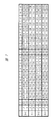
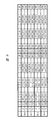
- FIG. 10 is an explanatory diagram showing an example of 10-bit deep color transmission timing in the transmission / reception system according to the second embodiment. It is explanatory drawing which shows an example of the transmission waveform which can extract the clock by this Embodiment 3.
- FIG. It is explanatory drawing which shows an example of the bit arrangement
- FIG. 10 is an explanatory diagram illustrating an example of transmission timing of video data of three primary color video signals RGB according to a fourth embodiment.
- FIG. 20 is an explanatory diagram illustrating an example of transmission timing of video data of three primary color signals according to a fifth embodiment.
- FIG. 20 is an explanatory diagram illustrating an example of transmission timing of video data of three primary color signals according to a sixth embodiment.
- FIG. 20 is an explanatory diagram illustrating an example of transmission timing of video data of three primary color signals according to a seventh embodiment.
- the constituent elements are not necessarily indispensable unless otherwise specified and apparently essential in principle. Needless to say.
- FIG. 1 is an explanatory diagram showing an example of the configuration of the transmission / reception system according to the first embodiment.
- the transmission / reception system has a configuration having a transmission device 10 as a source device and a reception device 15 as a sink device.
- the transmission device 10 is, for example, a player that reproduces a video recording medium such as an STB (Set Top Box), an optical disc or an HDD (Hard Disc Drive), a video camera, a smartphone, or a tablet PC (Personal Computer).
- the receiving device 15 is, for example, a television or a monitor.
- the transmission device 10 and the reception device 15 are connected by a transmission cable such as HDMI.
- a transmission cable such as HDMI.
- a connection using HDMI will be described as an example.
- the transmission apparatus 10 includes a signal source 101, an encryption unit 102, a transmission unit 103, a CP (Content Protection) processing unit 104, a CPU (Central Processing Unit) 105, an EDID (Extended Display Identification Data) reading unit 106, a detection unit 107, The power supply unit 108, the CEC (Consumer Electronics Control) unit 109, the setting storage unit 110, and the HEAC (HDMI Ethernet and Audio Audio return Channel) unit 111 are included.
- CP Content Protection
- CPU Central Processing Unit
- EDID Extended Display Identification Data
- the power supply unit 108, the CEC (Consumer Electronics Control) unit 109, the setting storage unit 110, and the HEAC (HDMI Ethernet and Audio Audio return Channel) unit 111 are included.
- the receiving device 15 includes a display unit 151, an encryption / decryption unit 152, a reception unit 153, a CP processing unit 154, a CPU 155, an EDID storage unit 156, a control unit 157, a CEC unit 159, and a HEAC unit 160.
- the transmission device 10 is controlled by the CPU 105.
- the receiving device 15 is controlled by the CPU 155.
- the CPU 105 and the CPU 155 are operated by a user via an MMI (Man-Machine Interface) device including a remote operation device (not shown) attached to the transmission device 10 or the reception device 15. Further, the transmission device 10 and the reception device 15 are connected by the HDMI cable 200 as described above.
- MMI Man-Machine Interface
- the signal source 101 is a video signal source such as an external video input terminal, a DVD (Digital Versatile Disc), or a broadcast receiving unit, and outputs the video signal to the encryption unit 102.
- a video signal source such as an external video input terminal, a DVD (Digital Versatile Disc), or a broadcast receiving unit, and outputs the video signal to the encryption unit 102.
- the encryption unit 102 encrypts the input video signal using, for example, HDCP (High-bandwidth Digital Content Protection), that is, performs content protection processing, and outputs the result to the transmission unit 103.
- HDCP High-bandwidth Digital Content Protection
- the encryption unit 102 performs encryption while maintaining the positions of the upper and lower bits of the video data.
- the transmission unit 103 converts the input video signal into a TMDS (Transmission Minimized Differential Signaling) serial transmission method, and sends it to the reception unit 153 of the reception device 15 via the four TMDS lines of the HDMI cable 200. To transmit.
- TMDS Transmission Minimized Differential Signaling
- the breakdown of the TMDS line is three data lines and one clock line which the HDMI cable 200 has.
- the CP processing unit 104 performs authentication processing of the receiving device 15.
- the CP processing unit 104 communicates with the CP processing unit 154 of the reception device 15 via a DDC (Display Data Channel) included in the HDMI cable 200, and the reception device 15 as a connection partner is authorized. It is authenticated whether the HDCP processing function is provided.
- DDC Display Data Channel
- the CP processing unit 104 After the authentication is obtained, the CP processing unit 104 outputs the encryption key information to the encryption unit 102. That is, the encryption unit 102 transmits the video signal obtained by subjecting the input video signal to content protection processing based on the key information input from the CP processing unit 104. If there is no key information that can decrypt the signal, it cannot be decrypted.
- the power supply unit 108 generates, for example, a DC voltage of about 5 V from an AC power supply (commercial power supply) or a battery (not shown) supplied to the transmission device.
- the DC voltage generated by the power supply unit 108 is supplied to the EDID storage unit 156 and the control unit 157 included in the reception device 15 via the + 5V power supply line included in the HDMI cable 200, respectively.
- the EDID reading unit 106 reads out the EDID stored in the EDID storage unit 156 of the receiving device 15 described later via the DDC line of the HDMI cable 200 and outputs the EDID to the CPU 105.
- the CPU 105 determines the format and transmission format of the video signal and audio signal to be transmitted based on the input EDID, and stores the setting information such as the format in the setting storage unit 110.
- the CPU 105 instructs the signal source 101 about the output format of the video signal and the audio signal. Then, control is performed so that the transmission unit 103 does not transmit the video signal until the initialization and the authentication processing by the CP processing unit 104 are completed.
- the detecting unit 107 When detecting the HPD signal, the detecting unit 107 outputs detection information of the HPD signal to the CPU 105.
- the HPD signal is a hot plug detection signal that determines whether or not the source device, that is, the transmission apparatus is connected to the sink device, that is, the reception apparatus.
- the HPD signal is transmitted from the control unit 157 included in the reception device 15 via an HPD (Hot Plug Detect) line included in the HDMI cable 200.
- HPD Hot Plug Detect
- the CEC unit 109 is connected to the CEC unit 159 of the receiving device 15 via the CEC line included in the HDMI cable 200, and transmits / receives CEC messages to / from each other.
- the CEC message is a message for performing device control such as transmission of a remote control signal and power on / standby.
- the HEAC unit 111 performs bidirectional Ethernet transmission and audio signal reception via a twisted pair line configured by the Utility line and the HPD line of the HDMI cable 200.
- the reception unit 153 receives the video or audio signal transmitted from the transmission device 10, returns the video signal to the original format from the serial transmission method, and outputs the video signal to the encryption / decryption unit 152. Further, the CP processing unit 154 outputs key information obtained through authentication with the CP processing unit 104 of the transmission device 10 to the encryption / decryption unit 152.
- the encryption / decryption unit 152 performs encryption / decryption processing on the video signal input from the reception unit 153 using the key information obtained from the CP processing unit 154 and outputs the video signal to the display unit 151.
- the display unit 151 displays the input video.
- the EDID storage unit 156 stores EDID, which is data indicating the characteristics of the receiving device 15 including receivable video signal, audio signal format, and transmission format.
- the EDID is transmitted in accordance with the reading operation of the EDID reading unit 106 of the transmission device 10 via the DDC line included in the HDMI cable 200.
- the control unit 157 transmits to the detection unit 107 of the transmission device 10 as an HPD signal that the reception device 15 is cable-connected to the transmission device 10 and the EDID can be read out.
- the CEC unit 159 transmits and receives CEC messages to and from the CEC unit 109 of the transmission device 10 via the CEC line included in the HDMI cable 200.
- the HEAC unit 160 performs bidirectional Ethernet transmission and audio signal transmission via a twisted pair line configured by a Utility line and an HPD line of the HDMI cable 200.
- the above is the basic operation process in the transmission device 10 and the reception device 15.
- FIG. 2 is an explanatory diagram illustrating an example of a configuration of the transmission unit 103 included in the transmission device 10 illustrated in FIG. 1 and the reception unit 153 included in the reception device 15.
- the transmission unit 103 includes a selector 201, a pseudo-random number generator 202, scramble providing units 203 and 213, encoding units 204 and 214, parallel-to-serial conversion units 205 and 215, a polarity control unit 206, A value output unit 207 is included.
- the receiving unit 153 includes a multi-value input unit 221, a serial-parallel conversion unit, 222 and 232, a decoding unit 223 and 233, a descrambling unit 224 and 234, a pseudo random number generator 225, a complex unit 226, and an error detection unit 227.
- a multi-value input unit 221 a serial-parallel conversion unit, 222 and 232, a decoding unit 223 and 233, a descrambling unit 224 and 234, a pseudo random number generator 225, a complex unit 226, and an error detection unit 227.
- the transmission device 10 serializes the upper bit and the lower bit of the video data of each pixel after adding the redundant bits and encoding them. Then, the serialized upper bits are weighted approximately twice or more than the serialized lower bits, and the analog addition is performed for transmission.
- the receiving apparatus calculates the cumulative disparity of the code to which redundant bits have been added by adding the weights to the upper bits and adding them to the lower bits.
- the DC balance is controlled by encoding so that the absolute value becomes small.
- the selector 201 divides input 8-bit video data, for example, into upper 4 bits and lower 4 bits, and a scramble providing unit 203 and a first scrambler serving as a second scramble unit. Each is input to the scramble provision unit 213 which becomes a part.
- the encryption unit 102 applies the encryption so that the upper 4 bits and the lower 4 bits of the video data are not mixed, so that the upper 4 bits having a large visual influence and the relatively small influence are obtained. The relationship of the lower 4 bits is maintained.
- the scramble providing units 203 and 213 scramble the input data by taking the exclusive OR (Ex-OR) of each input bit and the pseudo random number data output from the pseudo random number generator 202 and each bit, Output to the conversion units 204 and 214.
- the encoding unit 204 is a second encoding unit
- the encoding unit 214 is a first encoding unit.
- scramble processing is performed in which the bit position of the video data is not interchanged.
- the scramble providing units 203 and 213 change the bit position. For example, the bit position may not be maintained.
- an encryption unit may be arranged in place of the scramble providing units 203 and 213.
- EMI Electro-Magnetic Interference
- the encoding unit 204 adds redundancy in units of a total of 8 bits of the lower 4 bits of the video data for 2 pixels, and performs encoding to 10 bits by TMDS conversion, for example. Similarly, the encoding unit 214 encodes a total of 8 bits of the upper 4 bits of video data for 2 pixels into 10 bits.
- the difference between the number of “1” and the number of “0” is defined as disparity. If the accumulated disparity is positive, the DC balance is achieved by selecting a sign of 0 or a negative disparity, and if the accumulated disparity is negative, a disparity of 0 or a positive sign is selected.
- the encoding from 8 bits to 10 bits may use so-called 8B / 10B encoding used in DisplayPort (registered trademark).
- the DC balance by the same disparity is also taken in the 8B / 10B conversion.
- the 10-bit codes encoded by the encoding units 204 and 214 are input to the multi-level output unit 207 as serial bit strings by the parallel conversion units 205 and 215, respectively.
- the multi-value output unit 207 adds, for example, the upper bit with a weight twice as large as the lower bit, and outputs the result as a quaternary output from the transmission unit 103 and is transmitted to the reception unit 153.
- the upper bit is double the lower bit in terms of the influence on disparity. Therefore, when the disparity of the output code of the encoding unit 214 is +2, when converted to the output code of the encoding unit 204, it corresponds to twice the disparity +4.
- the polarity control unit 206 performs this calculation and controls the encoding units 204 and 214 so that the cumulative disparity is minimized.
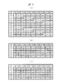
- FIG. 3 is an explanatory diagram showing an example of cumulative disparity control by the polarity control unit 206 of FIG.
- the disparity of the lower bit code is 0 and ⁇ 2
- the converted disparity of the upper bit code is 0 and ⁇ 4
- the previous cumulative disparity is 0, +2, +4, ⁇
- the code selection in case 2 and the total accumulated disparity in that case are shown in FIGS.
- the total accumulated disparity is the sum of the previous accumulated disparity and the converted disparity of the upper / lower bit code.
- the total disparity shown with an underline indicates a combination of codes that are not selected because the absolute value of the total disparity is large, and the disparity is the absolute value of the total disparity in the bold line frame.
- a combination of codes with small values is preferentially used.
- the disparity of the lower bit code is 0 and the disparity of the upper bit code is selected to be either +4 or ⁇ 4 in FIG.
- the absolute value of is 4. Therefore, either one can be selected, but by deciding which one to select in advance, the logic circuit can be rationalized and the fluctuation range of the total disparity value can be reduced. Further, the DC balance may be further improved by selecting +4 if it is ⁇ when looking at the history of the accumulated disparity before that, but not if it is +, and ⁇ 4 if it is +.
- the upper bit code selects 0 or +4, and when the previous cumulative disparity is 0 or negative, the upper bit code is the converted disparity. It is preferable to select 0 or +4 for the parity.
- the lower bit code takes a disparity 0 or -2 code when the upper bit code converted disparity is +4, and takes a disparity 0 or +2 code when the upper bit code converted disparity is -4.
- the converted disparity of the upper bit code When the converted disparity of the upper bit code is 0, it depends on the previous cumulative disparity, and when the previous cumulative disparity is 0 or -2, disparity 0 or +2, and when the previous cumulative disparity is +2 or +4, Select a disparity 0 or -2 code.
- the polarity control of the upper bits may be the same as TMDS for binary output or so-called 8B / 10B.
- the polarity control of the lower bits depend on the polarity control result of the upper bits, 4
- the accumulated disparity of the value output can be kept small and a good DC balance can be realized.
- the receiving unit 153 restores the signal received by the multi-value input unit 221 to lower bits and upper bits, and the serial-to-parallel conversion unit 222 and the first serial-to-parallel conversion unit, which become the second serial-to-parallel conversion unit, To the serial-parallel converter 232.
- the serial-parallel converters 222 and 232 convert the serial bit strings into 10-bit codes, respectively, and output them to the decoders 223 and 224, respectively.
- the error detection unit 227 detects an error such as no corresponding code or an error in the disparity value (when the code is different from the code selection technique described in FIG. 3), and the reliability of the transmission system is detected. Assess degree.
- the error detection unit 227 estimates 10-bit encoding when the decoded 8-bit valid data is input to the encoding units 204 and 214, and the result is the 10-bit code input to the decoding units 223 and 224. Different cases may be detected as transmission errors.
- the transmitting device If there are many errors and the reliability is low, it is transmitted to the transmitting device through the EDID storage unit 156, the CEC unit 159, etc., and the video format is changed to take measures such as changing the multilevel transmission to binary transmission or reducing the clock speed.
- the pseudorandom number generator 225 generates a pseudorandom number synchronized with the pseudorandom number generator 202 of the transmission unit 103.
- the descrambling units 224 and 234 scramble the 8-bit code output by the serial-parallel conversion units 222 and 232 and the 8-bit pseudorandom number generated by the pseudorandom number generator 225 and the exclusive OR for each bit. Is released.
- the scramble release unit 224 serves as a second scramble release unit, and the scramble release unit 234 serves as a first scramble release unit.
- the unscrambled upper bit group 8 bit code and lower bit group 8 bit are combined by a composite unit 226 which is a composite unit to obtain 8 bits of video data for 2 pixels.
- HDCP When the video signal is encrypted by HDCP, HDCP normally generates a 24-bit pseudo random number of 3 colors with 8 bits per pixel in synchronization with the same TMDS character clock as the pixel clock.
- the encryption unit 102 and the encryption / decryption unit 152 are preferably operated by a pixel clock corresponding to twice the TMDS character clock.
- the case of 8 bits per pixel has been described.
- the number of bits per pixel is expanded to 10 bits, 12 bits, or 16 bits to transmit a video signal with a smoother gradation. This is called a deep color mode in HDMI.
- FIG. 4 is an explanatory diagram showing an example of 10-bit deep color transmission timing in the transmission / reception system according to the second embodiment.
- FIG. 4 shows the 10-bit deep color transmission data described above in time series.
- 4A is an input of the selector 201
- FIG. 4B is an upper bit group output from the selector 201 to the scramble providing unit 213
- FIG. 4C is an output from the selector 201 to the scramble providing unit 203. Each lower bit group is shown.
- HDMI transmits, for example, three-color RGB (Red / Green / Blue) video signals as differential signals of 8 bits / character clock through independent TMDS lines.
- RGB Red / Green / Blue
- FIG. 4A among the 10-bit images A0 to A9 of the first pixel, 8 bits of the images A0 to A7 are transmitted in the clock 0 period, and the image is displayed at the first timing of the subsequent clock 1 period. A8 and A9 are transmitted.
- the selector 201 extracts the upper 5 bits from the 10-bit input data per pixel shown in FIG. 4A and rearranges them in units of 8 bits as shown in FIG. 4B. That is, the upper 5 bits A5 to A9 of the first pixel image and the upper 5 bits B5 to B7 of the second pixel image are transmitted in the clock 0 period.
- the remaining B8 and B9 in the upper 5 bits of the second pixel video, the upper 5 bits C5 to C9 of the third image video, and C0 among the upper 5 bits of the fourth pixel video are transmitted.
- the upper 5 bits of the video are assigned to an 8-bit transmission unit, and the upper 5 bits of the video for 8 pixels are transmitted in a 5-character clock period.
- the selector 201 takes out the lower 5 bits from the 10-bit input data per pixel shown in FIG. 4A and rearranges them in units of 8 bits as shown in FIG. 4C.
- the multi-value transmission is performed from the transmission unit 103 to the reception unit 153 after scrambling and encoding as in the first embodiment. Then, after decoding and descrambling, the signals shown in FIGS. 4B and 4C are reproduced and input to the composite unit 226.
- the composite unit 226 performs the reverse process of the rearrangement operation of the selector 201 to restore the 10-bit deep color video in FIG.
- multi-level transmission is not performed by dividing the upper 4 bits and the lower 4 bits of the 8-bit transmission unit into multi-level transmission, but by dividing the upper 5 bits and the lower 5 bits of a 10-bit video. Accordingly, when the error rate of the lower bit group is high, the influence on the video is limited to the lower bits of the video, and high-quality video transmission can be realized.
- the 10-bit deep color has been described as an example.
- 8 bits such as 12 bits and 16 bits, the same can be handled.
- the TMDS line of the HDMI cable 200 that connects the transmission unit 103 and the reception unit 153 shown in FIG. 1 is composed of three data lines and a clock line as described in the first embodiment. .
- FIG. 5 is an explanatory diagram showing an example of a transmission waveform from which a clock can be extracted according to the third embodiment.
- FIG. 5 shows an example of a waveform when the multilevel code has four levels.
- FIG. 6 is an explanatory diagram showing an example of bit arrangement in the transmission waveform shown in FIG.
- I indicates the bit string number in the word
- Ui indicates the i-th upper bit
- Di indicates the i-th lower bit.
- i is an integer of 0 or more.
- U0 and D0 are set to “0” and U1 and D1 are set to “1” to indicate the beginning of the word.
- A0 to A7, B0 to B7, C0 to C7, and D0 to D7 are 8-bit video data of the first pixel, the second pixel, the third pixel, and the fourth pixel, respectively.
- S0 to S3 are polarity codes of the subsequent bit string. If “0”, the subsequent 8-bit data is video data, and if “1”, the video data is inverted.
- the exclusive OR (ExOR) of the bits A4 to A7 and B4 to B7 and the polarity code S1 becomes the video data.
- S0 to S4 are determined by the polarity control unit 206 so that the absolute value of the total value of the accumulated disparity so far and the disparity of the subsequent bit string is minimized, and is encoded.
- the units 204 and 214 are controlled.
- the encoding units 204 and 214 can be realized by, for example, an exclusive OR circuit.
- the polarity code S1 of the upper bit may be determined first, and then the polarity code S0 of the lower bit may be determined.
- a combination that minimizes the accumulated disparity after the word transmission may be selected from the combinations of S1 and S3 by simply extending the word. If the cumulative disparity value after word transmission is determined from all combinations of the polarity control codes S0 to S3 in the word, the cumulative disparity value can be made smaller and the DC balance is improved. Thus, it is possible to realize a reliable video transmission with few errors.
- the word synchronization signal is always performed at the rising timing, but the falling timing may be used, or the rising and falling may be switched for each word.
- the rising and falling it is useful for grasping the characteristics of the transmission path, and there is an advantage that the reception error of the quaternary code can be suppressed low.
- FIG. 7 is an explanatory diagram showing an example of rearrangement of video data when a TMDS line and a clock line are combined and a video signal capable of clock extraction is transmitted simultaneously for 4 channels.
- a luminance color difference signal format is used, the luminance signal Y per pixel is 12 bits, and the color difference signals Cb and Cr are 10 bits each. It aims at assigning more bits to the luminance signal than the color difference signal to make the gradation display smoother.
- the first numbers 0 to 3 following the luminance signal Y and the color difference signals Cb and Cr indicate pixel numbers, and the second numbers 0 to B (in hexadecimal notation) indicate bit numbers.
- the upper bits Yj8 to YjB of the luminance signal of the jth pixel are transmitted with the upper bits of ch1, and the subsequent upper bits Yj6 and Yj7 are transmitted with the upper bits of ch3.
- j is an integer of 0 or more.
- the high-order bits Cbj6 to Cbj9 of the color difference signal of the j-th pixel are transmitted with the high-order bits of ch0, and the subsequent high-order bits Cbj5 are transmitted with the high-order bits of ch3.
- the upper bits Crj6 to Crj9 of the other color difference signal of the 0th pixel are transmitted as the upper bits of ch2, and the subsequent upper bits Crj5 are transmitted as the upper bits of ch3.
- the selector 201 rearranges the multi-valued transmission so that the high-order bits of the video signal are assigned to the high-order bits of the multi-value transmission, and the composite unit 226 restores it.
- the composite unit 226 restores it.
- ch. 3 is divided into luminance signals Yj0 to Yj3 and color difference signals Cbj0, Cbj1, Crj0, and Crj1, and if image quality is not an issue, the ch3 transmission is stopped to save energy, and each ch0 to Ch2 switches to 8-bit video. It may be rearranged so as to facilitate.
- the luminance signal is 12 bits.
- the most significant 2 bits may be assigned to the HDR (High Dynamic Range) control signal of the luminance color difference signal, and the luminance color difference signals Y, Cb, and Cr may be 10 bits each.
- the HDR control signal video transmission with a wide dynamic range can be realized by switching the setting of the maximum luminance and the minimum luminance of EOTF (Electro-Optical-Transfer Function). A plurality of types of EOTF may be switched.
- This HDR control signal may be prepared for each pixel, or the number of switching types may be increased in units of a plurality of pixels. If a 2-bit HDR control signal is prepared for each pixel, four types of EOTF can be switched. The HDR parameter with a large amount of information is transmitted as metadata transmitted during the blanking period of the video, etc., and by switching four types among them, finer control can be realized.
- the EMI noise may be reduced by reducing the amplitude of the word synchronization signal as (1, 0, 0, 1) or (0, 1, 1, 0). Further, by mixing the large amplitude and the small amplitude synchronization, for example, (0, 0, 1, 1) (0, 1, 1, 0) (1, 1, 0, 0) (1, 0, It may be switched to 0,1).
- the polarity of the data string that continues with the type of word synchronization may be indicated, and the polarity bit may also be used to increase the encoding efficiency.
- FIG. 8 is an explanatory diagram showing an example of transmission timing of video data of the three primary color video signals RGB according to the fourth embodiment.
- FIG. 8 shows an example in which the primary color signal G is 10 bits per pixel, and the primary color signals R and B are 9 bits each for a total of 28 bits.
- the upper bits Gj6 to Gj9 of the primary color signal G of the jth pixel are the upper bits of ch1
- the upper bits Bj5 to Gj8 of the primary color signal B are the upper bits of ch0
- the upper bits Rj5 to Rj8 of the primary color signal R are the upper bits of ch2. It is transmitted with. Further, redundant codes Ej1 to Ej3 for error correction are respectively transmitted with the upper bits of ch3.
- one word excluding the synchronization bit is divided into the first half and the second half, and the unit is 2 pixels including the polarity control bit.
- the upper 4 bits of the primary color signal RGB of the 0th pixel and the 1st pixel are 24 bits in total and the 3 bits of ch0 to 2 polarity codes S01, S02, S03 are 27 bits in total, for error correction of 8 bits. Redundant codes E00 to E03 and E10 to E13 are assigned.
- the polarity code S31 of ch3 is not determined until the redundant codes E00 to E03 and E10 to E13 are determined, it is not included in the total code length of the redundant code calculation.
- the polarity code S31 is incorrect, it is recognized as an uncorrectable error of 2 bits or more.
- the decoding unit 223 may invert the polarity code S31 and decode the redundant codes E00 to E03 and E10 to E13 again.
- the decoding when the polarity code S31 is both “0” and “1” may be calculated at the same time, and the decoding result with fewer error bits may be employed.
- the redundant code length for 1-bit error correction may be 6 bits. Therefore, 2 bits out of 8 bits of the redundant code are allocated to the primary color signals R and B, and the effective code length 29 The gradation may be enhanced as a bit.
- the primary color signal R or B of 3 pixels may be converted to 10 bits, or may be assigned to the primary color signal R of the first pixel and the primary color signal B of the second pixel.
- the HDR control signal described in the third embodiment may be used.
- the redundant code length may be 6 bits
- the coding of ch3 U2 to U10 (assigned to S21, E00 to E03, and E10 to E13 in FIG. 8) is changed to an encoding method that does not require transmission of polarity bits. It may be replaced.
- 9 bits U2 to U10 are divided into 3 groups each having 3 bits, and each group allocates 2 bits of necessary redundant bits.
- the lower bits Gj2 to Gj5 of the primary color signal G of the jth pixel are transmitted by the lower bits of ch1, and the lower bits Gj0 and Gj1 are transmitted by the lower bits of ch3.
- the lower bits Bj1 to Gj4 of the primary color signal B are transmitted with the lower bits of ch0, and the lower bit Bj0 of the primary color signal B is transmitted with the lower bits of ch3.
- the lower bits Rj1 to Rj4 of the primary color signal R are transmitted as the lower bits of ch2, and the lower bit Rj0 of the primary color signal R is transmitted as the lower bits of ch3.
- the lower bit of the primary color signal has less influence on the image quality than the upper bit, so instead of not using an error correction code, priority is given to smooth gradation display by increasing the number of gradations.
- G is 10 bits
- G and B are 9 bits each.
- the error correction described above may be applied to the lower bits.
- the total code length is 71 bits in total of U2 to U10 of ch0 to 3 and D2 to 10, excluding U2 to which the polarity bit S31 of ch3 is assigned.
- the redundant code is 8 bits (E00 to E04 and E10 to E14), and the effective bit is 63 bits (total primary color signal RGB for 2 pixels is 56 bits and polarity bit is 7 bits), and 1-bit error correction is possible. Redundant codes are easy to ensure reliability when placed in higher bits with relatively high transmission reliability.
- FIG. 9 is an explanatory diagram showing an example of transmission timing of video data of three primary color signals according to the fifth embodiment.
- FIG. 9 shows an example in which three primary color signals of 12 bits for each color and 36 bits in total are transmitted.
- Each channel transmits primary color signals R, G, and B in order for each pixel.
- ch0 transmits 0th and 4th pixels
- ch1 transmits 1st and 5th pixels
- ch2 transmits 2nd and 6th pixels
- ch3 transmits 3rd and 7th pixels.
- HDMI uses 10-bit transmission for each channel as a unit, and performs encoding by adding redundant bits to 8-bit RGB primary color signals in ch0 to ch2. Therefore, in the case of 40-bit transmission unit, the HDMI is 24 bits ⁇ 4 pixels transmission, whereas in the fifth embodiment, the transmission is 36 bits ⁇ 8 pixels. As described above, since 3 times as much video data can be transmitted efficiently, high-resolution video transmission with high resolution and high dynamic range can be realized.
- the video data for one pixel is transmitted in half the HDMI ratio, so there is an advantage that the timing between the video pixel clock and the transmission clock can be easily taken.
- a twisted pair line composed of a Utility line and an HPD line of the HDMI cable 200 is prepared for Ethernet bidirectional transmission.
- FIG. 10 is an explanatory diagram showing an example of transmission timing of video data of three primary color signals according to the sixth embodiment.
- FIG. 10 the difference from FIG. 9 of the fifth embodiment is that a channel 4 is added, 40B / 36B conversion is set to 100B / 96 conversion, each primary color 12-bit transmission is 8-bit transmission, and the transmission system is focused on resolution. It is a point.
- the primary color signals Rj0 to Rj7, Gj0 to Gj7, and Bj0 to Bj7 are collectively described as RGBj.
- j is an integer greater than or equal to 0 and expressed in two digits. Since the basic operation is the same, description of the operation is omitted.
- FIG. 11 is an explanatory diagram showing an example of transmission timing of video data of three primary color signals according to the seventh embodiment.
- each bit transmission 4 bits can be transmitted by 2 bits per channel, and 10 channels can be transmitted because there are 5 channels. By assigning these 10 bits to 10 bits of each primary color signal, transmission can be performed efficiently.
- the high-order bits of each primary color signal are assigned to the high-order bits of each channel to ensure reliability.
- channel ch4 using a twisted pair line for Ethernet bidirectional transmission may be inferior in high-speed transmission compared to channels ch0 to ch3 using other TMDS lines, relatively low-order bit data is assigned to ch4. Therefore, even if the error rate of the transmission path increases, the influence on the image quality can be reduced.
- Embodiments 1 to 7 improve the transmission speed by multi-value transmission controlled by DC balance, suppress the influence on image quality, and support a high dynamic range. Image quality transmission can be realized.
- a part of the configuration of one embodiment can be replaced with the configuration of another embodiment, and the configuration of another embodiment can be added to the configuration of one embodiment. .
Landscapes
- Engineering & Computer Science (AREA)
- Physics & Mathematics (AREA)
- Computer Hardware Design (AREA)
- General Physics & Mathematics (AREA)
- Theoretical Computer Science (AREA)
- Spectroscopy & Molecular Physics (AREA)
- Computer Networks & Wireless Communication (AREA)
- Signal Processing (AREA)
- Two-Way Televisions, Distribution Of Moving Picture Or The Like (AREA)
Abstract
送信装置10および受信装置15からなる送受信システムにおいて、送信装置10では、符号化部204が、符号化部214が符号化した符号データの累積ディスパリティ、符号化部204が符号化した符号データの累積ディスパリティ、および符号化部214が決定した符号データのディスパリティから符号データを決定して出力する。また、受信装置15では、複合部226が、スクランブル解除部234およびスクランブル解除部224がスクランブルを解除したデータを複合して暗号復号部152が取り扱う入力単位に並べ替えて該暗号復号部152に出力する。
Description
本発明は、送信装置、受信装置、および送受信システムに関し、特に、映像伝送における信頼性の向上に有効な技術に関する。
デジタル映像や音声などのインタフェース規格としてHDMI(High-Definition Multimedia Interface)が知られている。このHDMI(登録商標)のインタフェース規格は、非特許文献1に開示されている。
また、特許文献1には「HDMIでも15Gbps、20Gbpsといった現在の規格上での最高値以上への拡張が、今後求められる状況にある」ことから、「コネクタ(プラグ、レセプタクル)の互換を保」ちつつ、「現在の3つのデータ差動ラインペア数を、4つ以上に増やすことである。それに応じて、データを伝送するレーンが増える分だけデータレートを上げること」が記載されている。
特許文献2には「1ワードNビット(Nは正の整数)のディジタルデータを上位mビット(mは正の整数でN>m)と下位(N-m)ビットとに分離する分離手段と、上記上位mビットの各ビット毎の値を表す信号を取り出す上位記録信号形成手段と、上記下位(N-m)ビットの各ビット毎の値を表す信号を取り出す下位記録信号形成手段と、上記上位記録信号形成手段及び上記下位記録信号形成手段からそれぞれ出力される信号について、上記上位側のビットの信号の振幅を上記下位側のビットの信号の振幅よりも大きくしてビット毎に合成することで多値化する多値化合成手段とを有し、上記多値化合成手段にて合成された多値信号を伝送すること」が記載されている。
High-Definition Multimedia Interface Specification Version 1.3a, November 10,2008
4K/8Kなどに代表される高画素数/高解像度に対応するディスプレイが普及するに伴い、HDMIにおいても、4K/8Kなどの大容量のデータの高速に伝送することが求められる。
HDMIでは、データ伝送クロックを高周波化することによって、データ伝送の高速化に対応している。しかしながら、データ伝送クロックを高周波化することによって、HDMIケーブルの高周波損失が大きくなってしまい、データ伝送の信頼性が損なわれる恐れが生じてしまう。
また、HDMIコネクタのピン数を増加させることによって、伝送データ量を増加させることも考えられるが、その場合、HDMI規格に合致しなくなり、既存のHDMIケーブルなどが使用できなくなってしまうという問題がある。
本発明の目的は、映像データの多値レベルのシリアル伝送における信頼性を確保することのできる技術を提供することにある。
本発明の前記ならびにその他の目的と新規な特徴については、本明細書の記述および添付図面から明らかになるであろう。
本願において開示される発明のうち、代表的なものの概要を簡単に説明すれば、次のとおりである。
すなわち、代表的な送信装置は、セレクタ、第1のスクランブル部、第1の符号化部、第2のスクランブル部、第2の符号化部、および多値出力部を有する。セレクタは、映像データを上位ビット群と下位ビット群とに振り分ける。第1のスクランブル部は、セレクタが振り分けた上位ビット群をスクランブルする。
第1の符号化部は、第1のスクランブル部がスクランブルしたデータを符号化する。第2のスクランブル部は、セレクタが振り分けた下位ビット群をスクランブルする。第2の符号化部は、第2のスクランブル部がスクランブルしたデータを符号化する。多値出力部は、第1の符号化部が符号化したデータの各々のビットに、第2の符号化部が符号化したデータの各ビットの少なくとも2倍の重みをつけて多値化してシリアル出力する。
そして、第2の符号化部は、第1の符号化部が符号化した符号データの累積ディスパリティ、第2の符号化部が符号化した符号データの累積ディスパリティ、および第1の符号化部が決定した符号データのディスパリティから符号データを決定して出力する。
特に、第1の符号化部は、第1の符号化部が出力する符号データの累積ディスパリティの絶対値が小さくなるように符号データを選び、第2の符号化部は、第1の符号化部が出力する累積ディスパリティに重みと等しい値をかけあわせた数値に、第2の符号化部が出力する符号データの累積ディスパリティを加算した合計ディスパリティの絶対値が小さくなるように符号データを決定して出力する。
また、代表的な受信装置は、多値入力部、第1の直並変換部、第1の復号部、第1のスクランブル解除部、第2の直並変換部、第2の復号部、第2のスクランブル解除部、および複合部を有する。
多値入力部は、受信した上位ビットが下位ビットに比べて少なくとも2倍の重みをつけて加算された多値データを上位ビットと下位ビットとに復元する。第1の直並変換部は、多値入力部が復元した上位ビットを並列化して並列データに変換する。
第1の復号部は、第1の直並変換部が並列化した並列データを復号する。第1のスクランブル解除部は、第1の復号部が復号したデータのスクランブルを解除する。第2の直並変換部は、多値入力部が復元した下位ビットを並列化して並列データに変換する。第2の復号部は、第2の直並変換部が並列化した並列データを復号する。
第2のスクランブル解除部は、第2の復号部が復号したデータのスクランブルを解除する。複合部は、第1のスクランブル解除部および第2のスクランブル解除部から出力されるスクランブルを解除したデータから映像データを生成する。暗号復号部は、複合部が生成した映像データの暗号復号化を行う。
また、複合部は、第1のスクランブル解除部および第2のスクランブル解除部がスクランブルを解除したデータを複合して暗号復号部が取り扱う入力単位に並べ替えて出力する。
特に、受信装置は、第1の復号部および第2の復号部が並列データを復号する際に、並列データの伝送誤りを検出する誤り検出回路を有する。
この誤り検出回路は、第1の復号部および第2の復号部が復号したデータから、第1の復号部および第2の復号部に入力される並列データをそれぞれ推定し、推定した並列データと、第1の直並変換部および第2の直並変換部がそれぞれ並列化した並列データとの差異から伝送誤りを検出する。
本願において開示される発明のうち、代表的なものによって得られる効果を簡単に説明すれば以下のとおりである。
(1)映像伝送の信頼性を向上させることができる。
(2)高画質化および高速性を両立させた映像伝送を実現することができる。
以下の実施の形態においては便宜上その必要があるときは、複数のセクションまたは実施の形態に分割して説明するが、特に明示した場合を除き、それらはお互いに無関係なものではなく、一方は他方の一部または全部の変形例、詳細、補足説明等の関係にある。
また、以下の実施の形態において、要素の数等(個数、数値、量、範囲等を含む)に言及する場合、特に明示した場合および原理的に明らかに特定の数に限定される場合等を除き、その特定の数に限定されるものではなく、特定の数以上でも以下でもよい。
さらに、以下の実施の形態において、その構成要素(要素ステップ等も含む)は、特に明示した場合および原理的に明らかに必須であると考えられる場合等を除き、必ずしも必須のものではないことは言うまでもない。
同様に、以下の実施の形態において、構成要素等の形状、位置関係等に言及するときは特に明示した場合および原理的に明らかにそうではないと考えられる場合等を除き、実質的にその形状等に近似または類似するもの等を含むものとする。このことは、上記数値および範囲についても同様である。
また、実施の形態を説明するための全図において、同一の部材には原則として同一の符号を付し、その繰り返しの説明は省略する。なお、図面をわかりやすくするために平面図であってもハッチングを付す場合がある。
以下、実施の形態を詳細に説明する。
(実施の形態1)
〈送受信信システムの構成例〉
以下、実施の形態を詳細に説明する。
(実施の形態1)
〈送受信信システムの構成例〉
図1は、本実施の形態1による送受信システムにおける構成の一例を示す説明図である。
送受信システムは、図1に示すように、ソースデバイスである送信装置10およびシンクデバイスである受信装置15を有する構成からなる。
送信装置10は、例えばSTB(Set Top Box)、光ディスクやHDD(Hard Disc Drive)などの映像記録メディアを再生するプレーヤ、ビデオカメラ、スマートフォン、あるいはタブレットPC(Personal Computer)などである。また、受信装置15は、例えばテレビやモニタなどである。
送信装置10と受信装置15とは、HDMIなどの伝送ケーブルにて接続されている。以下、本実施の形態では、HDMIによる接続を例にとって説明する。
送信装置10は、信号源101、暗号化部102、送信部103、CP(Content Protection)処理部104、CPU(Central Processing Unit)105、EDID(Extended Display Identification Data)読み出し部106、検出部107、電源部108、CEC(Consumer Electronics Control)部109、設定記憶部110、およびHEAC(HDMI Ethernet and Audio return Channel)部111を有する。
また、受信装置15は、表示部151、暗号復号部152、受信部153、CP処理部154、CPU155、EDID記憶部156、制御部157、CEC部159、およびHEAC部160を有する。
〈送信装置および受信装置の基本動作〉
送信装置10は、CPU105によって制御される。同様に、受信装置15は、CPU155によって制御される。これらCPU105およびCPU155は、当該送信装置10若しくは受信装置15に付属する図示しない、遠隔操作機器などを含む、MMI(Man-Machine Interface)機器を介してユーザが操作する。また、送信装置10と受信装置15とは、前述したようにHDMIケーブル200によって接続されている。
送信装置10において、信号源101は、外部映像入力端子、DVD(Digital Versatile Disc)、あるいは放送受信部などの映像信号ソースであり、映像信号を暗号化部102に出力する。
暗号化部102は、入力された映像信号を例えば、HDCP(High-bandwidth Digital Content Protection)によって暗号化、すなわちコンテンツ保護処理して、送信部103に出力する。
暗号化部102は、映像データの上位ビットと下位ビットの位置を保ちながら暗号化する。送信部103は、入力された映像信号をTMDS(Transmission Minimized Differential Signaling)方式のシリアル伝送方式に変換して、HDMIケーブル200が有する4本のTMDS線を介して、受信装置15の受信部153に伝送する。ここで、TMDS線の内訳は、HDMIケーブル200が有する3本のデータ線および1本のクロック線である。
このとき、CP処理部104は、受信装置15の認証処理を行う。この認証処理は、CP処理部104が、HDMIケーブル200が有するDDC(Display Data Channel)線を介して受信装置15のCP処理部154との通信を行い、接続相手である受信装置15が正規のHDCP処理機能を備えるか否かを認証する。
認証がとれた後、CP処理部104は、暗号化の鍵情報を暗号化部102に出力する。すなわち、暗号化部102は、入力された映像信号を、CP処理部104から入力された鍵情報に基づいてコンテンツ保護処理した映像信号を伝送するため、受信装置15は、当該コンテンツ保護された映像信号を復号可能な鍵情報がなければ、復号できない。
電源部108は、送信装置に供給される図示しないAC電源(商用電源)やバッテリなどから、例えば5V程度の直流電圧を生成する。電源部108が生成した直流電圧は、HDMIケーブル200が有する+5V電源線を介して、受信装置15が有するEDID記憶部156および制御部157にそれぞれ供給される。
EDID読み出し部106は、HDMIケーブル200が有するDDC線を介して,後述する受信装置15のEDID記憶部156に格納されたEDIDを読み出し、そのEDIDをCPU105に出力する。
CPU105は、入力されたEDIDに基づいて、伝送する映像信号や音声信号のフォーマットおよび伝送形式などを決めて、そのフォーマットなどの設定情報を設定記憶部110に記憶させる。
さらに、CPU105は、信号源101に映像信号や音声信号の出力フォーマットなどを指示する。そして、この初期化と前記したCP処理部104による認証処理が終了するまで、送信部103が映像信号を送信しないように制御する。
検出部107は、HPD信号を検出した際に、該HPD信号の検出情報をCPU105に出力する。HPD信号は、ソースデバイス、すなわち送信装置が、シンクデバイス、すなわち受信装置と接続された状態か否かを判断するホットプラグ検出信号である。HPD信号は、HDMIケーブル200が有するHPD(Hot Plug Detect)線を介して受信装置15が有する制御部157から送信される。
CEC部109は、受信装置15のCEC部159とHDMIケーブル200が有するCEC線を介して接続されており、CECメッセージを相互に送受信する。CECメッセージは、リモコン信号の伝送や電源オン/スタンバイなどの機器制御を行うメッセージである。
HEAC部111は、HDMIケーブル200が有するUtility線およびHPD線にて構成したツイストペア線を介してEthernet双方向伝送や、音声信号の受信を行う。
受信装置15では、送信装置10から伝送される映像や音声信号を、受信部153が受信し、シリアル伝送方式から、元の形式の映像信号に戻し、暗号復号部152に出力する。また、CP処理部154は、送信装置10のCP処理部104との認証を通じて得られた鍵情報を暗号復号部152に出力する。
暗号復号部152は、CP処理部154から得られた鍵情報を使って、受信部153より入力された映像信号を暗号復号化処理して表示部151に出力する。表示部151は、入力された映像を表示する。
EDID記憶部156は、受信可能な映像信号、音声信号のフォーマット、および伝送形式を含む受信装置15の特徴を示すデータであるEDIDを記憶する。このEDIDは、HDMIケーブル200が有するDDC線を介して送信装置10のEDID読み出し部106の読み出し動作に合わせて送信される。
制御部157は、受信装置15が送信装置10にケーブル接続されて、EDIDが読み出しできることをHPD信号として送信装置10の検出部107に送信する。
CEC部159は、送信装置10のCEC部109と、HDMIケーブル200が有するCEC線を介して、CECメッセージを相互に送受信する。HEAC部160は、HDMIケーブル200が有するUtility線およびHPD線にて構成したツイストペア線を介して、Ethernet双方向伝送や、音声信号の送信を行う。
以上が、送信装置10および受信装置15における基本的な動作処理である。
図2は、図1の送信装置10が有する送信部103および受信装置15が有する受信部153における構成の一例を示す説明図である。
送信部103は、図2に示すように、セレクタ201、疑似乱数発生器202、スクランブル付与部203,213、符号化部204,214、並直変換部205,215、極性制御部206、および多値出力部207を有する。
また、受信部153は、多値入力部221、直並変換部、222,232、復号部223,233、スクランブル解除部224,234、疑似乱数発生器225、複合器226、および誤り検出部227を有する。
〈動作の概要〉
〈動作の概要〉
送受信システムにおいて、送信装置10は、各画素の映像データの上位ビットと下位ビットを、それぞれ冗長ビットを付与して符号化した上でシリアル化する。そして、シリアル化上位ビットにシリアル化下位ビットのほぼ2倍またはそれ以上の重みをつけてアナログ加算して伝送する。
受信装置は、冗長ビットを付与した符号の累積ディスパリティを、上位ビットには前記重みをかけて下位ビットと合計して算出する。その絶対値が小さくなるように、符号化することによって、DCバランスを制御する。
〈送信装置および受信装置の動作例〉
〈送信装置および受信装置の動作例〉
まず、送信部103において、セレクタ201は、入力される例えば8ビットの映像データを、上位4ビットと下位4ビットとに分けて、第2のスクランブル部となるスクランブル付与部203および第1のスクランブル部となるスクランブル付与部213にそれぞれ入力する。
前述したように、暗号化部102は、映像データの上位4ビットと下位4ビットとが入り混じらない暗号化をかけておくことにより、視覚的に影響の大きい上位4ビットと比較的影響の小さい下位4ビットの関係は保たれている。
スクランブル付与部203,213は、各入力ビットと疑似乱数発生器202が出力する疑似乱数データと各ビットとの排他的論理和(Ex-OR)をとることによって、入力データをスクランブルして、符号化部204,214に出力する。符号化部204は、第2の符号化部となり、符号化部214は、第1の符号化部となる。
本実施の形態では、映像データのビット位置が入れ替わらないスクランブル処理を施しているが、上位4ビットと下位4ビットとを振り分けた後なので、スクランブル付与部203,213は、ビット位置が変化するなど、ビット位置を維持できないものであっても構わない。
コンテンツ保護として用いる暗号化にビット位置を維持できない方式を用いる場合は、このスクランブル付与部203,213に代えて暗号化部を配置してもよい。スクランブルをかけることにより、映像データの偏りを避けることができ、特定周波数のEMI(Electro-Magnetic Interference)ノイズが生じることを避けられる。
符号化部204は、2画素分の映像データの下位4ビットの合計8ビットを単位として冗長性を加えて、例えばTMDS変換により10ビットへの符号化を行う。同様に、符号化部214は、2画素分の映像データの上位4ビットの合計8ビットを10ビットへ符号化を行う。
10ビット符号変換では、“1”の数と“0”の数の差をディスパリティと定義する。そして、累計ディスパリティが正であれば、ディスパリティが0又は負の符号を、累計ディスパリティが負であれば、ディスパリティが0又は正の符号を選ぶことによってDCバランスをとっている。
なお、8ビットから10ビットへの符号化は、DisplayPort(登録商標)にて使われている、いわゆる8B/10B符号化を使用してもよい。8B/10B変換でも同様なディスパリティによるDCバランスをとっている。
符号化部204,214にて符号化された各10ビット符号は、並直変換部205,215によってそれぞれシリアル・ビット列にして多値出力部207に入力される。多値出力部207は、例えば上位ビットに下位ビットの2倍の重みをつけて加算し、4値出力として送信部103から出力されて、受信部153へ送信される。
このように、上位ビットに下位ビットの2倍の重みをつけることによって、ディスパリティへの影響も、上位ビットは下位ビットの2倍となる。したがって、符号化部214の出力符号のディスパリティが+2の場合には、符号化部204の出力符号に換算するとその2倍のディスパリティ+4に相当する。
このように、下位ビット群のディスパリティに換算して、累計ディスパリティを計算するとよい。極性制御部206は、この計算を行い、累計ディスパリティが最小になるように、符号化部204,214をそれぞれ制御する。
〈累計ディスパリティの制御例〉
〈累計ディスパリティの制御例〉
図3は、図2の極性制御部206による累計ディスパリティの制御の一例を示した説明図である。
ここでは、説明を簡単にするため、下位ビット符号のディスパリティを0と±2、上位ビット符号の換算ディスパリティを0と±4の例にとり、前累計ディスパリティが0、+2、+4、-2の場合の符号選択とその場合の合計累計ディスパリティをそれぞれ図3(a)~図3(d)に示している。なお、合計累計ディスパリティは、前累計ディスパリティと上位・下位ビット符号の換算ディスパリティの和である。
また、図3において、下線付にて示す合計ディスパリティは、合計ディスパリティの絶対値が大きいために選択されない符号の組み合わせを示しており、ディスパリティは、太線枠内の合計ディスパリティの絶対値が小さい符号の組み合わせを優先して用いる。
ここで、前累計ディスパリティが0の場合、図3(a)において、下位ビット符号のディスパリティが0であって、上位ビット符号のディスパリティが+4と-4のどちらを選んでも合計ディスパリティの絶対値は4である。よって、どちらを選んでもよいが、どちらを選ぶかあらかじめ決めておくことにより、論理回路を合理化することができるとともに、合計ディスパリティ値の変動幅を小さくすることができる。また、前符号まではなく、それ以前の累計ディスパリティの履歴を見て-であれば+4を、+であれば-4を選んでDCバランスをさらに改善してもよい。
図3からわかるように、前累計ディスパリティが正の場合、上位ビット符号は、換算ディスパリティが0または+4を選択し、前累計ディスパリティが0または負の場合、上位ビット符号は、換算ディスパリティが0または+4を選択するとよい。
下位ビット符号は、上位ビット符号の換算ディスパリティが+4の場合、ディスパリティ0または-2の符号を、上位ビット符号の換算ディスパリティが-4の場合、ディスパリティ0または+2の符号をとる。
上位ビット符号の換算ディスパリティが0の場合は、前累計ディスパリティに依存し、前累計ディスパリティが0または-2の時にディスパリティ0または+2を、前累計ディスパリティが+2または+4の場合、ディスパリティ0または-2の符号を選択する。
このように、上位ビットの極性制御は、2値出力用のTMDSやいわゆる8B/10Bと同様であってもよいが、下位ビットの極性制御が上位ビットの極性制御結果に依存させることで、4値出力の累計ディスパリティを小さく保ち、良好なDCバランスを実現することができるという利点がある。
一方、受信部153では、多値入力部221が受信した信号を下位ビットと上位ビットとに復元して第2の直並変換部となる直並変換部222および第1の直並変換部となる直並変換部232へそれぞれ出力する。直並変換部222,232は、シリアル・ビット列をそれぞれ10ビット符号に変換して復号部223,224へそれぞれ出力する。
第2の複合部となる復号部223および第1の複合部となる復号部233は、10ビット符号から8ビットの有効データを復号して、スクランブル解除部224,234へそれぞれ出力する。8ビットの有効データ復号時には、誤り検出部227が該当コードなしや、ディスパリティ値の異常などの誤り(図3において説明した符号選定技術と異なる符号である場合)を検出し、伝送系の信頼度を評価する。
誤り検出部227は、復号された8ビットの有効データを符号化部204,214に入力した場合の10ビット符号化を推定し、その結果が復号部223,224に入力された10ビット符号と異なる場合を伝送誤りとして検出してもよい。
誤りが多く信頼度が低い場合は、EDID記憶部156やCEC部159などを通じて送信装置に伝えて、映像フォーマットを変更して多値伝送を2値伝送化やクロック速度低減などの処置を図る。
疑似乱数発生器225は、送信部103の疑似乱数発生器202と同期した疑似乱数を生成する。スクランブル解除部224,234は、それぞれ直並変換部222,232が出力する8ビット符号と疑似乱数発生器225が生成した8ビットの疑似乱数とビット毎に排他的論理和をとることによって、スクランブルを解除する。スクランブル解除部224は、第2のスクランブル解除部となり、スクランブル解除部234は、第1のスクランブル解除部となる。
スクランブルを解除された上位ビット群の8ビット符号と下位ビット群の8ビットは、複合部となる複合器226によって合成され、8ビット映像データが2画素分得られる。
映像信号をHDCPにて暗号化する場合、通常、HDCPは、画素クロックと同じTMDSキャラクタクロックに同期して1画素8ビットで3色分の24ビットの疑似乱数を発生させている。
これに対し、上述した4値伝送では、TMDSキャラクタの1クロックで2画素分の48ビットの暗号化が必要である。このため、暗号化部102や暗号復号部152は、TMDSキャラクタクロックの2倍に相当する画素クロックによって動作させるとよい。
以上、述べてきたように、DCバランス制御を適用した4値差動伝送によって、2値差動伝送に比べて2倍の映像データを伝送することができる。また、各画素の上位ビットの伝送エラーを下位ビットより抑えることにより、万一エラーが生じても画質への影響を小さくすることができる。
(実施の形態2)
〈概要〉
(実施の形態2)
〈概要〉
前記実施の形態1においては、1画素8ビットの場合を説明した。1画素当たりのビット数は、10ビット、12ビット、あるいは16ビットに拡張してより階調が滑らかな映像信号を伝送する場合がある。これをHDMIでは、ディープカラーモードと呼んでいる。
〈送受信システムの動作例〉
〈送受信システムの動作例〉
本実施の形態2では、上述したディープカラーモードにおけるディープカラー伝送による送受信システムによる動作について説明する。
ここでは、前記実施の形態1と同様に、図2の送信部103および受信部153の説明図を用いて、特に送信部103が有するセレクタ201および受信部153が有する複合器226に注目して動作を説明する。
図4は、実施の形態2による送受信システムにおける10ビットのディープカラーの伝送タイミングの一例を示した説明図である。
この図4は、上記した10ビットのディープカラーの伝送データを時系列的に表示したものである。図4(a)は、セレクタ201の入力、図4(b)は、セレクタ201がスクランブル付与部213へ出力する上位ビット群、図4(c)は、セレクタ201がスクランブル付与部203へ出力する下位ビット群をそれぞれ示している。
HDMIは、例えば3色RGB(Red Green Blue)の映像信号をそれぞれ独立したTMDS線によって、8ビット/キャラクタクロックの差動信号で伝送している。図4(a)に示すように、最初の画素の10ビット映像A0~A9のうち、クロック0期間では、映像A0~A7の8ビットを伝送し、続くクロック1期間の最初のタイミングにて映像A8,A9を伝送する。
次の画素の10ビット映像B0~B9のうち、クロック1期間では、映像B0~B5の6ビットを伝送し、続くクロック2期間の最初のタイミングで映像B6~B9を伝送する。このように2ビットずつタイミングをずらせていくことで、5クロック期間で4画素分の10ビット映像を伝送している。
セレクタ201は、図4(a)にて示す画素当たり10ビット入力データから上位5ビットを取り出し、図4(b)に示すように、8ビット単位に並べ替える。すなわち、第1画素映像の上位5ビットA5~A9と、第2画素映像の上位5ビットの内B5~B7とをクロック0期間で伝送する。
続くクロック1期間では、第2画素映像の上位5ビットの内の残りB8とB9、第3画像映像の上位5ビットC5~C9、第4画素映像の上位5ビットのうち、C0を伝送する。このように映像の上位5ビットを8ビットの伝送単位に割り当て、5キャラクタクロック期間で8画素分の映像の上位5ビットを伝送している。
同様に、セレクタ201は、図4(a)に示す画素当たり10ビット入力データから下位5ビットを取り出し、図4(c)に示すように8ビット単位に並べ替える。
セレクタ201で映像の上位5ビット群と下位5ビット群に分離した後は、前記実施の形態1と同様にスクランブルや符号化後、送信部103から受信部153へ多値伝送する。そして、復号、スクランブル解除を経て、図4(b)および図4(c)に示した信号に再生して複合器226に入力する。複合器226は、セレクタ201の並べ替え動作の逆処理を行って、図4(a)の10ビットディープカラー映像を復元する。
このように、伝送単位の8ビットの上位4ビットと下位4ビットとに分けて多値化伝送するのではなく、10ビット映像の上位5ビットと下位5ビットとに分けて多値化することにより、下位ビット群のエラーレートが高い場合に、映像へ与える影響を映像の下位ビットにとどめ、高画質な映像伝送を実現することができる。
また、ディープカラー対応の信号源や暗号化などの処理を変えることなく、セレクタ201や複合器226の並べ替え動作だけで多値化伝送対応を実現することができるため、既存の回路構成との整合性がよい利点もある。
以上、本実施の形態2では、10ビットのディープカラーを例にとって説明してきたが、12ビットや16ビットなど、8ビットと異なる映像の場合でも同様に対応することができる。
さらに、これまで述べてきた非圧縮映像伝送ではなく、圧縮映像伝送の場合は、上位ビット群と下位ビット群とに分けた並べ替えに代えて、画質に重要な影響の出るデータを上位ビット群、画質への影響が比較的軽微なデータを下位ビット群に割り当てて並べ替えることにより、本実施の形態に述べた技術を適用することができる。
(実施の形態3)
〈概要〉
(実施の形態3)
〈概要〉
送受信システムにおいて、図1に示す送信部103と受信部153とを接続するHDMIケーブル200のTMDS線は、前記実施の形態1において述べたように3本のデータ線およびクロック線によって構成されている。
本実施の形態3においては、データからクロックを抽出できる符号化形式とすることにより、クロック線でもデータを伝送して、より高速な信号伝送を実現することのできる技術にて説明する。
〈送受信システムの動作例〉
〈送受信システムの動作例〉
図5は、本実施の形態3によるクロックを抽出することができる伝送波形の一例を示す説明図である。この図5では、多値符号として4レベルの場合の波形例を示している。
図5において、伝送波形は、各20個の上位ビットU0~U19と下位ビットD0~D19とを1ワード単位とし、先頭の各2ビットをワード同期信号としてU0=D0=“0”、U1=D1=“1”を与え、最大振幅として同期をとりやすくしている。このワード同期信号から、各ビットデータを抽出するビットクロックやワード周期のワードクロックが容易に得られる。
図6は、図5に示す伝送波形におけるビット配置の一例を示す説明図である。
iは、ワード内のビット列番号を示し、Uiはi番目の上位ビット、Diはi番目の下位ビットを示す。ここで、iは0以上の整数である。前述のとおり、U0とD0とを“0”、U1とD1とを“1”としてワードの始まりを示す。
A0~A7、B0~B7、C0~C7、D0~D7は、それぞれ第1画素、第2画素、第3画素、第4画素の各8ビット映像データである。S0~S3は、続くビット列の極性符号であり、“0”であれば続く8ビットのデータは映像データとなり、“1”であれば映像データを反転したものである。
例えばA4~A7とB4~B7の各ビットと極性符号S1の排他的論理和(ExOR)が映像データとなる。S0~S4は、実施の形態1で述べたように、それまでの累積ディスパリティと、続くビット列のディスパリティの合計値の絶対値が最小となるように極性制御部206が決定し、符号化部204,214を制御する。符号化部204,214は、例えば排他的論理和回路によって実現することができる。
前記実施の形態1にて説明したように、上位ビットの極性制号S1を先に決め、次に下位ビットの極性符号S0を決めてもよい。さらに、8ビットデータ単位ではなく、ワード単に拡張してS1とS3の組み合わせの中で、ワード伝送後の累積ディスパリティが最少となる組み合わせを選んでもよい。また、ワード内の極性制御符号S0~S3のすべての組み合わせの中からワード伝送後の累積ディスパリティ値を決めるようにすると、累積ディスパリティ値をより小さくすることが可能となり、DCバランスがよくなる。このことから、誤りの少ない信頼性の高い映像伝送を実現することができる。
図5に示す波形例では、ワード同期信号は常に立ち上がりタイミングで行っているが、立ち下がりタイミングを用いてもよいし、ワード毎に立ち上がりと立ち下がりとを切り換えてもよい。立ち上がりと立ち下がりとの双方を使うことによって、伝送路の特性把握に役立ち、4値符号の受信エラーを低く抑えることができる利点がある。
図7は、TMDS線とクロック線とを合わせて4ch同時に、クロック抽出可能な映像信号を伝送する場合の映像データ並び替えの一例を示した説明図である。
映像データとしては、輝度色差信号形式とし、画素当たり輝度信号Yは12ビット、色差信号Cb,Crは、各10ビットの例を挙げている。色差信号より、輝度信号に多くのビットを割り当て、階調表示をより滑らかにすることを狙っている。
図7では、ワード同期のi=0,1のビットを省略し、極性符号と映像データとを表示している。輝度信号Yと色差信号Cb,Crに続く最初の数字0~3は画素番号を、2つ目の数字0~B(16進数表記)はビット番号を示している。
第j画素の輝度信号の上位ビットYj8~YjBをch1の上位ビットで、続く上位ビットYj6とYj7をch3の上位ビットで伝送している。ここで、jは0以上の整数である。
第j画素の色差信号の上位ビットCbj6~Cbj9をch0の上位ビットで、続く上位ビットCbj5をch3の上位ビットで伝送している。第0画素のもう1つの色差信号の上位ビットCrj6~Crj9をch2の上位ビットで、続く上位ビットCrj5をch3の上位ビットとして伝送している。
このように、映像信号の上位ビットが多値伝送の上位ビットに割り当てられるように、セレクタ201が並び替えて多値伝送し、複合器226がそれを復元する。これによって、映像信号の上位ビットの信頼性を確保しながら、良好な画質を実現することができる。
なお、ch.3に輝度信号Yj0~Yj3と色差信号Cbj0,Cbj1,Crj0,Crj1を分担させて、画質が気にならない場合はch3伝送を停止させて省エネを図り、ch0~Ch2で各8ビット映像への切り換えを容易にするように並び替えておいてもよい。
また、上記では、輝度信号を12ビットとしているが、最上位2ビットを輝度色差信号のHDR(High Dynamic Range)制御信号に割り当て、輝度色差信号Y,Cb,Crを各10ビットとしてもよい。HDR制御信号の例としては、EOTF(Electro Optical Transfer Function)の最大輝度や最小輝度の設定を切り換えて広いダイナミックレンジの映像伝送を実現することができる。また、複数種類のEOTFを切り換えてもよい。
このHDR制御信号は、画素毎に用意してもよいし、複数画素を単位として切り換え種類を増やしてもよい。画素単位で2ビットのHDR制御信号を用意すると4種類のEOTFを切り換えることができる。情報量の多いHDRパラメータは、映像の帰線期間などで伝送されるメタデータとして伝送し、それらの中から4種類を切り換えることにより、よりきめ細かな制御を実現することができる。
以上、ワード同期信号として(U0,D0,U1,D1)=(0,0,1,1)の例を説明してきたが、各ビットを反転させた(1,1,0,0)であっても同様な効果が得られる。また、ワード毎に各ビットを反転させて、立ち上がりと立ち下がりとをバランスさせて、DCバランスをさらに改善させてもよい。
ワード同期信号を(1,0,0,1)や(0,1,1,0)として小振幅化して、EMIノイズを軽減させてもよい。さらに、大振幅と小振幅同期を混在させて、例えば4ワード周期で(0,0,1,1)(0,1,1,0)(1,1,0,0)(1,0,0,1)と切り換えてもよい。また、ワード同期の種類で続くデータ列の極性を示し、極性ビットを兼用して符号化効率を高めてもよい。
(実施の形態4)
〈概要〉
(実施の形態4)
〈概要〉
本実施の形態4では、前記実施の形態3の図7における輝度色差信号Y,Cb,Crの伝送に代えて、3原色映像信号RGBを伝送する例について説明する。
〈送受信システムの動作例〉
〈送受信システムの動作例〉
図8は、本実施の形態4による3原色映像信号RGBの映像データの伝送タイミングの一例を示す説明図である。
この図8では、1画素当たり、原色信号Gが10ビット、原色信号RとBは、各9ビットの合計28ビット伝送例を示している。
第j画素の原色信号Gの上位ビットGj6~Gj9をch1の上位ビットで、原色信号Bの上位ビットBj5~Gj8をch0の上位ビットで、原色信号Rの上位ビットRj5~Rj8をch2の上位ビットで伝送している。さらに、誤り訂正用冗長符号Ej1~Ej3をch3の上位ビットでそれぞれ伝送している。
誤り訂正は、同期ビットを除く1ワードを前半と後半とに分け、極性制御ビットを含めた2画素を単位としている。例えば第0画素と第1画素の各原色信号RGBの上位4ビット合計24ビットとch0~2の極性符号S01、S02,S03の3ビットの合計27ビットとに対して、8ビットの誤り訂正用冗長符号E00~E03とE10~E13とを付与する。
すなわち、総符号長35ビットのうち、有効符号長27ビット、冗長8ビットの構成からなる例えばBCH符号を用いることによって、1ビットの誤り訂正が可能となる。
ch3の極性符号S31は、冗長符号E00~E03とE10~E13が決まってからでないと決まらないので、冗長符号計算の総符号長には入れていない。受信部153において冗長符号を復号化する際に、極性符号S31が誤っていると2ビット以上の訂正不可能な誤りとして認識される。
この場合は、極性符号S31の伝送誤りとして、復号部223が極性符号S31を反転させて再度冗長符号E00~E03とE10~E13とを復号するとよい。また、極性符号S31が“0”と“1”との双方の場合の復号化を同時に計算し、誤りビットが少ない方の復号結果を採用するようにしてもよい。
また、有効符号長27ビットにおいて、1ビットの誤り訂正の冗長符号長は、6ビットでよいことから、冗長符号8ビットのうち、2ビットを原色信号RやBに割り当てて、有効符号長29ビットとして階調性を高めてもよい。
2画素分に対して2ビットなので、3画素の原色信号RまたはBを10ビット化してもよいし、最初の画素の原色信号Rと2番目の画素の原色信号Bに割り当ててもよい。原色信号RやBへ割り当てに代えて、実施の形態3において述べたHDR制御信号としてもよい。
さらに、冗長符号長が6ビットでよいことから、ch3のU2~U10(図8では、S21、E00~E03、E10~E13に割り当てている)の符号化を極性ビット伝送不要な符号化方式に代えてもよい。
例えば、U2~U10の9ビットを3ビットずつの3グループに分け、各グループは、必要な冗長ビットを2ビットずつ割り当てる。例えば、2ビットの冗長ビットの後ろに“0”を付与した3ビット符号とその反転波形を割り当て、送信時の極性パリティ絶対値が最小になる符号を選ぶ。このようにして極性ビットを使用しない符号化を採用してもよい。
以上により、上位ビットの信頼性を確保しながら、良好な画質を実現することができる。
一方、第j画素の原色信号Gの下位ビットGj2~Gj5をch1の下位ビットで、下位ビットGj0とGj1とをch3の下位ビットで伝送する。原色信号Bの下位ビットBj1~Gj4をch0の下位ビットで、原色信号Bの下位ビットBj0をch3の下位ビットで伝送する。原色信号Rの下位ビットRj1~Rj4をch2の下位ビットで、原色信号Rの下位ビットRj0をch3の下位ビットで伝送する。
原色信号の下位ビットは、上位ビットに比べて画質への影響が軽微なため、誤り訂正符号を使わない代わりに、階調数を増やして滑らかな階調表示を優先させている。この例では、Gは10ビット、GとBは、それぞれ9ビットの階調表示を実現している。
なお、前述した誤り訂正を下位ビットにも適用させてもよい。この場合、総符号長は、ch3の極性ビットS31を割り当てたU2を除く、ch0~3のU2~U10とD2~10の合計71ビットである。
冗長符号は8ビット(E00~E04とE10~E14)、有効ビットは63ビット(2画素分の原色信号RGB合計56ビットと極性ビット7ビット)であり、1ビットの誤り訂正ができる。冗長符号は、伝送の信頼性が比較的高い上位ビットに配置すると信頼性を確保しやすい。
以上、2画素単位での誤り訂正符号を用いた例を紹介したが、4画素単位、すなわちワード単位での誤り訂正符号としてもよい。さらには、8画素単位等に拡張して、バースト誤り耐性を強化してもよい。
(実施の形態5)
〈概要〉
(実施の形態5)
〈概要〉
前記実施の形態4は、伝送路を4chと20B/16B変換、4値伝送を併用した例について述べたが、本実施の形態5では、符号化を高効率化できる40B/36B変換を用いた例について説明する。
〈送受信システムの動作例〉
〈送受信システムの動作例〉
図9は、実施の形態5による3原色信号の映像データの伝送タイミングの一例を示す説明図である。この図9においては、各色12ビット、合計36ビットの3原色信号を伝送する例を示している。
各chの上位ビットUiと下位ビットDiとは、映像データ36ビット(i=3~20,22~40)の他、極性ビット2ビット(i=2,21)とワード同期信号2ビット(図示していないi=0,1)の40ビットで1ワードを構成している。
各chは、画素毎に原色信号RとG、Bを順番に伝送する。ch0は、第0と第4画素を、ch1は、第1と第5画素を、ch2は、第2と第6画素を、ch3は、第3と第7画素を伝送する。
HDMIは、ch毎に10ビット伝送を単位として、ch0~ch2にて各8ビットのRGB原色信号に冗長ビットを付与した符号化を行って伝送している。したがって、40ビット伝送単位の場合には、HDMIが24ビット×4画素伝送であるのに対して、本実施の形態5では、36ビット×8画素伝送となる。このように、3倍の映像データを効率よく伝送することができるので、高解像度、高ダイナミックレンジの高画質映像伝送を実現することができる。
1画素36ビット映像伝送しながらも、1画素分の映像データをHDMI比、半分の時間で伝送するので、映像の画素クロックと伝送クロック間のタイミングがとりやすい利点がある。
例えばフレームレート120Hz/36ビット伝送時は、4値伝送、60Hz/24ビット伝送時は、2値伝送と切り換えが容易である。4値伝送の伝送誤り率が増加してきたら2値伝送へ切り換えてノイズを軽減することもできる。
(実施の形態6)
〈概要〉
(実施の形態6)
〈概要〉
前記実施の形態1の図1の構成において、HDMIケーブル200のUtility線とHPD線とで構成したツイストペア線がEthernet双方向伝送用に用意されている。
このツイストペア線を5番目のチャンネル、すなわちch4として映像伝送を行うと、既存のHDMIケーブルを使いながら、さらなる高速伝送が可能である。本実施の形態6では、100B/96B変換によって、さらに伝送効率を増やした伝送例について説明する。
〈送受信システムの動作例〉
〈送受信システムの動作例〉
図10は、実施の形態6による3原色信号の映像データの伝送タイミングの一例を示す説明図である。
図10において、前記実施の形態5の図9と異なる点は、ch4を追加し、40B/36B変換を100B/96変換とし、各原色12ビット伝送を8ビット伝送として解像度を重視した伝送方式としている点である。
また、記述を簡略化するため、原色信号Rj0~Rj7,Gj0~Gj7,Bj0~Bj7をまとめてRGBjとして表記している。ただし、jは0以上の整数で2桁表記である。基本的な動作は同様であるので、動作説明は省略する。
このように、5番目のチャンネル、すなわちch4として映像伝送を行うことによって、さらなる高速伝送を可能とすることができる。
(実施の形態7)
〈概要〉
(実施の形態7)
〈概要〉
本実施の形態7においては、前記実施の形態6と同様に、5チャンネル伝送と100B/96B変換を採用し、各原色10ビット伝送を行った例について説明する。
〈送受信システムの動作例〉
〈送受信システムの動作例〉
図11は、実施の形態7による3原色信号の映像データの伝送タイミングの一例を示す説明図である。
各ビット伝送において、4値伝送によりチャネル当たり2ビットで、5チャネルあることから10ビット伝送できる。この10ビットを各原色信号の10ビットに割り当てることで効率よく伝送できる。各原色信号の上位ビットは、各チャネルの上位ビットに割り当てて信頼性を確保している。
さらに、Ethernet双方向伝送用のツイストペア線によるチャネルch4は、他のTMDS線によるチャネルch0~ch3に比べて高速伝送性が劣る場合が考えられるので、ch4には、比較的下位のビットデータを割り当てて、万一伝送路の誤り率が増えても、画質への影響を軽減することができる。
以上、述べてきたように、実施の形態1~7の技術により、DCバランス制御された多値伝送によって伝送速度の向上を図ると共に、画質への影響を抑制し、高ダイナミックレンジに対応した高画質伝送を実現することができる。
また、コンテンツ保護の暗号処理が24ビット(各原色当たり8ビット)単位である場合でも、8ビットの伝送単位ではなく、映像データ単位での、多値伝送の上位ビットと下位ビットへの並び替えを行う。
これによって、8ビット以外の10ビット、12ビット、16ビットなどのいわゆるディープカラーの上位ビットを信頼性よく伝送することができる。さらに、チャネル増や符号化効率を高めた高速伝送との併用により、さらなる高速化を実現することができる。
以上、本発明者によってなされた発明を実施の形態に基づき具体的に説明したが、本発明は前記実施の形態に限定されるものではなく、その要旨を逸脱しない範囲で種々変更可能であることはいうまでもない。
なお、本発明は上記した実施の形態に限定されるものではなく、様々な変形例が含まれる。例えば、上記した実施の形態は本発明を分かりやすく説明するために詳細に説明したものであり、必ずしも説明した全ての構成を備えるものに限定されるものではない。
また、ある実施の形態の構成の一部を他の実施の形態の構成に置き換えることが可能であり、また、ある実施の形態の構成に他の実施の形態の構成を加えることも可能である。また、各実施の形態の構成の一部について、他の構成の追加、削除、置換をすることが可能である。
10 送信装置
15 受信装置
101 信号源
102 暗号化部
103 送信部
104 CP処理部
106 EDID読み出し部
107 検出部
108 電源部
109 CEC部
110 設定記憶部
111 HEAC部
115 複合器
151 表示部
152 暗号復号部
153 受信部
154 CP処理部
156 EDID記憶部
157 制御部
159 CEC部
160 HEAC部
200 HDMIケーブル
201 セレクタ
202 疑似乱数発生器
203 スクランブル付与部
204 符号化部
205 並直変換部
206 極性制御部
207 多値出力部
213 スクランブル付与部
214 符号化部
221 多値入力部
222 直並変換部
223 復号部
224 スクランブル解除部
225 疑似乱数発生器
226 複合器
227 誤り検出部
232 直並変換部
233 復号部
15 受信装置
101 信号源
102 暗号化部
103 送信部
104 CP処理部
106 EDID読み出し部
107 検出部
108 電源部
109 CEC部
110 設定記憶部
111 HEAC部
115 複合器
151 表示部
152 暗号復号部
153 受信部
154 CP処理部
156 EDID記憶部
157 制御部
159 CEC部
160 HEAC部
200 HDMIケーブル
201 セレクタ
202 疑似乱数発生器
203 スクランブル付与部
204 符号化部
205 並直変換部
206 極性制御部
207 多値出力部
213 スクランブル付与部
214 符号化部
221 多値入力部
222 直並変換部
223 復号部
224 スクランブル解除部
225 疑似乱数発生器
226 複合器
227 誤り検出部
232 直並変換部
233 復号部
Claims (11)
- 映像データを上位ビット群と下位ビット群とに振り分けるセレクタと、
前記セレクタが振り分けた前記上位ビット群をスクランブルする第1のスクランブル部と、
前記第1のスクランブル部がスクランブルしたデータを符号化する第1の符号化部と、
前記セレクタが振り分けた前記下位ビット群をスクランブルする第2のスクランブル部と、
前記第2のスクランブル部がスクランブルしたデータを符号化する第2の符号化部と、
前記第1の符号化部が符号化したデータの各々のビットに、前記第2の符号化部が符号化したデータの各ビットの少なくとも2倍の重みをつけて多値化してシリアル出力する多値出力部と、
を有し、
前記第2の符号化部は、前記第1の符号化部が符号化した符号データの累積ディスパリティ、前記第2の符号化部が符号化した符号データの累積ディスパリティ、および前記第1の符号化部が決定した符号データのディスパリティから符号データを決定して出力する、送信装置。 - 請求項1記載の送信装置において、
前記第1の符号化部は、前記第1の符号化部が出力する符号データの累積ディスパリティの絶対値が小さくなるように符号データを選び、
前記第2の符号化部は、前記第1の符号化部が出力する累積ディスパリティに前記重みと等しい値をかけあわせた数値に、前記第2の符号化部が出力する符号データの累積ディスパリティを加算した合計ディスパリティの絶対値が小さくなるように符号データを決定して出力する、送信装置。 - 請求項1記載の送信装置において、
入力された前記映像データを暗号化して前記セレクタに出力する暗号化部を有し、
前記セレクタは、前記暗号化部が暗号化した前記映像データの出力単位が1画素分の映像データより小さい場合に、前記暗号化した映像データの少なくとも2出力単位にまたがって1画素分の前記映像データの上位ビット群と下位ビット群とに振り分ける、送信装置。 - 上位ビットが下位ビットに比べて少なくとも2倍の重みをつけて加算された多値データを上位ビットと下位ビットとに復元する多値入力部と、
前記多値入力部が復元した前記上位ビットを並列化して並列データに変換する第1の直並変換部と、
前記第1の直並変換部が並列化した前記並列データを復号する第1の復号部と、
前記第1の復号部が復号したデータのスクランブルを解除する第1のスクランブル解除部と、
前記多値入力部が復元した前記下位ビットを並列化して並列データに変換する第2の直並変換部と、
前記第2の直並変換部が並列化した前記並列データを復号する第2の復号部と、
前記第2の復号部が復号したデータのスクランブルを解除する第2のスクランブル解除部と、
前記第1のスクランブル解除部および前記第2のスクランブル解除部から出力されるスクランブルを解除したデータから映像データを生成する複合部と、
前記複合部が生成した前記映像データの暗号復号化を行う暗号復号部と、
を有し、
前記複合部は、前記第1のスクランブル解除部および前記第2のスクランブル解除部がスクランブルを解除したデータを複合して前記暗号復号部が取り扱う入力単位に並べ替えて出力する、受信装置。 - 請求項4記載の受信装置において、
前記第1の復号部および前記第2の復号部が前記並列データを復号する際に、前記並列データの伝送誤りを検出する誤り検出回路を有する、受信装置。 - 請求項5記載の受信装置において、
前記誤り検出回路は、前記第1の復号部および前記第2の復号部が復号したデータから、前記第1の復号部および前記第2の復号部に入力される前記並列データをそれぞれ推定し、推定した前記並列データと前記第1の直並変換部および前記第2の直並変換部がそれぞれ並列化した並列データとの差異から伝送誤りを検出する、受信装置。 - ソースデバイスである送信装置およびシンクデバイスである受信装置を具備する送受信システムであって、
前記送信装置は、
映像データを上位ビット群と下位ビット群とに振り分けるセレクタと、
前記セレクタが振り分けた前記上位ビット群をスクランブルする第1のスクランブル部と、
前記第1のスクランブル部がスクランブルしたデータを符号化する第1の符号化部と、
前記セレクタが振り分けた前記下位ビット群をスクランブルする第2のスクランブル部と、
前記第2のスクランブル部がスクランブルしたデータを符号化する第2の符号化部と、
前記第1の符号化部が符号化したデータの各々のビットに、前記第2の符号化部が符号化したデータの各ビットの少なくとも2倍の重みをつけて多値化してシリアル出力する多値出力部と、
を有し、
前記受信装置は、
前記多値出力部から出力された多値化データを上位ビットと下位ビットとに復元する多値入力部と、
前記多値入力部が復元した前記上位ビットを並列化して並列データに変換する第1の直並変換部と、
前記第1の直並変換部が並列化した前記並列データを復号する第1の復号部と、
前記第1の復号部が復号したデータのスクランブルを解除する第1のスクランブル解除部と、
前記多値入力部が復元した前記下位ビットを並列化して並列データに変換する第2の直並変換部と、
前記第2の直並変換部が並列化した前記並列データを復号する第2の復号部と、
前記第2の復号部が復号したデータのスクランブルを解除する第2のスクランブル解除部と、
前記第1のスクランブル解除部および前記第2のスクランブル解除部から出力されるスクランブルを解除したデータから映像データを生成する複合部と、
前記複合部が生成した前記映像データの暗号復号化を行う暗号復号部と、
を有し、
前記第2の符号化部は、前記第1の符号化部が符号化した符号データの累積ディスパリティ、前記第2の符号化部が符号化した符号データの累積ディスパリティ、および前記第1の符号化部が決定した符号データのディスパリティから符号データを決定して出力し、
前記複合部は、前記第1のスクランブル解除部および前記第2のスクランブル解除部がスクランブルを解除したデータを複合して前記暗号復号部が取り扱う入力単位に並べ替えて出力する、送受信システム。 - 請求項7記載の送受信システムにおいて、
前記第1の符号化部は、前記第1の符号化部が出力する符号データの累積ディスパリティの絶対値が小さくなるように符号データを選び、
前記第2の符号化部は、前記第1の符号化部が出力する累積ディスパリティに前記重みと等しい値をかけあわせた数値に、前記第2の符号化部が出力する符号データの累積ディスパリティを加算した合計ディスパリティの絶対値が小さくなるように符号データを決定して出力する、送受信システム。 - 請求項7記載の送受信システムにおいて、
前記送信装置は、入力された前記映像データを暗号化して前記セレクタに出力する暗号化部を有し、
前記セレクタは、前記暗号化部が暗号化した前記映像データの出力単位が1画素分の映像データより小さい場合に、前記暗号化した映像データの少なくとも2出力単位にまたがって1画素分の前記映像データの上位ビット群と下位ビット群とに振り分ける、送受信システム。 - 請求項7記載の送受信システムにおいて、
前記受信装置は、前記第1の復号部および前記第2の復号部が前記並列データを復号する際に、前記並列データの伝送誤りを検出する誤り検出回路を有する、送受信システム。 - 請求項10記載の送受信システムにおいて、
前記誤り検出回路は、前記第1の復号部および前記第2の復号部が復号したデータから、前記第1の復号部および前記第2の復号部に入力される前記並列データをそれぞれ推定し、推定した並列データと、前記第1の直並変換部および前記第2の直並変換部がそれぞれ並列化した並列データとの差異から伝送誤りを検出する、送受信システム。
Priority Applications (1)
| Application Number | Priority Date | Filing Date | Title |
|---|---|---|---|
| PCT/JP2015/053870 WO2016129088A1 (ja) | 2015-02-12 | 2015-02-12 | 送信装置、受信装置、および送受信システム |
Applications Claiming Priority (1)
| Application Number | Priority Date | Filing Date | Title |
|---|---|---|---|
| PCT/JP2015/053870 WO2016129088A1 (ja) | 2015-02-12 | 2015-02-12 | 送信装置、受信装置、および送受信システム |
Publications (1)
| Publication Number | Publication Date |
|---|---|
| WO2016129088A1 true WO2016129088A1 (ja) | 2016-08-18 |
Family
ID=56614580
Family Applications (1)
| Application Number | Title | Priority Date | Filing Date |
|---|---|---|---|
| PCT/JP2015/053870 Ceased WO2016129088A1 (ja) | 2015-02-12 | 2015-02-12 | 送信装置、受信装置、および送受信システム |
Country Status (1)
| Country | Link |
|---|---|
| WO (1) | WO2016129088A1 (ja) |
Citations (6)
| Publication number | Priority date | Publication date | Assignee | Title |
|---|---|---|---|---|
| JPS5910056A (ja) * | 1982-06-30 | 1984-01-19 | インタ−ナシヨナル ビジネス マシ−ンズ コ−ポレ−シヨン | コ−ド生成方法 |
| JPH0275224A (ja) * | 1988-09-12 | 1990-03-14 | Sony Corp | データ伝送装置 |
| JP2001333217A (ja) * | 2000-05-18 | 2001-11-30 | Gigalink Co Ltd | 電話線を通じて音声とデータとを送受信するデータ送受信器 |
| JP2008526170A (ja) * | 2004-12-29 | 2008-07-17 | エニグマ セミコンダクター,インコーポレイテッド | 16b/10s符号化装置および方法 |
| JP2010213263A (ja) * | 2009-02-10 | 2010-09-24 | Panasonic Corp | 送信装置 |
| WO2013061520A1 (ja) * | 2011-10-26 | 2013-05-02 | パナソニック株式会社 | 多値振幅変調装置、多値振幅復調装置、および、それらを用いた伝送システム、ならびに、多値振幅変調方法、および、多値振幅復調方法 |
-
2015
- 2015-02-12 WO PCT/JP2015/053870 patent/WO2016129088A1/ja not_active Ceased
Patent Citations (6)
| Publication number | Priority date | Publication date | Assignee | Title |
|---|---|---|---|---|
| JPS5910056A (ja) * | 1982-06-30 | 1984-01-19 | インタ−ナシヨナル ビジネス マシ−ンズ コ−ポレ−シヨン | コ−ド生成方法 |
| JPH0275224A (ja) * | 1988-09-12 | 1990-03-14 | Sony Corp | データ伝送装置 |
| JP2001333217A (ja) * | 2000-05-18 | 2001-11-30 | Gigalink Co Ltd | 電話線を通じて音声とデータとを送受信するデータ送受信器 |
| JP2008526170A (ja) * | 2004-12-29 | 2008-07-17 | エニグマ セミコンダクター,インコーポレイテッド | 16b/10s符号化装置および方法 |
| JP2010213263A (ja) * | 2009-02-10 | 2010-09-24 | Panasonic Corp | 送信装置 |
| WO2013061520A1 (ja) * | 2011-10-26 | 2013-05-02 | パナソニック株式会社 | 多値振幅変調装置、多値振幅復調装置、および、それらを用いた伝送システム、ならびに、多値振幅変調方法、および、多値振幅復調方法 |
Similar Documents
| Publication | Publication Date | Title |
|---|---|---|
| JP4229836B2 (ja) | 一群の受信ワードの各ワードを単一送信ワードにマッピングすることで連続リンク送信上のシンボル間干渉効果を低減させる方法および装置。 | |
| KR100552833B1 (ko) | 시리얼 링크를 통한 전송시 심벌 간의 간섭 효과를 감소시키기 위한 인코딩 방법 및 시스템 | |
| US8780932B2 (en) | Video signal transmission device, video signal reception device, and video signal transmission system | |
| US9210010B2 (en) | Methods and apparatus for scrambling symbols over multi-lane serial interfaces | |
| KR101696056B1 (ko) | 제어 심볼의 지능적 스크램블링을 위한 방법 및 장치 | |
| US8378860B2 (en) | Method and system for generating high definition multimedia interface (HDMI) codewords using a TMDS encoder/decoder | |
| US8810560B2 (en) | Methods and apparatus for scrambler synchronization | |
| KR100810815B1 (ko) | 등화 신호들 중 하나로부터 생성되는 제어 신호에 응답하여다수의 신호를 적응성 등화하기 위한 방법 및 회로 | |
| US7146051B2 (en) | Apparatus for and method of transmitting optical signal of graphic signal | |
| TWI565254B (zh) | 於多媒體介面中減少射頻干擾 | |
| WO2007132877A1 (ja) | 通信システム、送信装置及び受信装置、通信方法、並びにプログラム | |
| US8478914B2 (en) | Display apparatus, video signal transmission method for display apparatus, transmitting apparatus, and transmission method of video signal | |
| US9191700B2 (en) | Encoding guard band data for transmission via a communications interface utilizing transition-minimized differential signaling (TMDS) coding | |
| TW201801534A (zh) | 影像信號發送裝置、影像信號接收裝置、及影像信號傳送系統 | |
| JP3851904B2 (ja) | 一群の受信ワードの各ワードを単一送信ワードにマッピングすることで連続リンク送信上のシンボル間干渉効果を低減させる方法および装置。 | |
| JPWO2017085969A1 (ja) | フレーム生成装置、フレーム生成方法、画像合成装置、画像合成方法、信号生成装置、信号生成方法、画像伝送システムおよび画像伝送方法 | |
| KR20250033987A (ko) | 데이터 처리 장치 및 데이터 구동 장치 | |
| JP2006050353A (ja) | 通信方法、送信装置及び通信システム |
Legal Events
| Date | Code | Title | Description |
|---|---|---|---|
| 121 | Ep: the epo has been informed by wipo that ep was designated in this application |
Ref document number: 15881963 Country of ref document: EP Kind code of ref document: A1 |
|
| NENP | Non-entry into the national phase |
Ref country code: DE |
|
| 122 | Ep: pct application non-entry in european phase |
Ref document number: 15881963 Country of ref document: EP Kind code of ref document: A1 |
|
| NENP | Non-entry into the national phase |
Ref country code: JP |