본 발명의 바람직한 실시예에 대해 구체적으로 설명하며, 그 예는 첨부된 도면에 나타낸다. 첨부된 도면을 참조한 아래의 상세한 설명은 본 발명의 실시예에 따라 구현될 수 있는 실시예만을 나타내기보다는 본 발명의 바람직한 실시예를 설명하기 위한 것이다. 다음의 상세한 설명은 본 발명에 대한 철저한 이해를 제공하기 위해 세부 사항을 포함한다. 그러나 본 발명이 이러한 세부 사항 없이 실행될 수 있다는 것은 당업자에게 자명하다.Preferred embodiments of the present invention will be described in detail, examples of which are illustrated in the accompanying drawings. DETAILED DESCRIPTION The following detailed description with reference to the accompanying drawings is intended to explain preferred embodiments of the invention rather than to show only embodiments that may be implemented in accordance with embodiments of the invention. The following detailed description includes details to provide a thorough understanding of the present invention. However, it will be apparent to one skilled in the art that the present invention may be practiced without these details.
본 발명에서 사용되는 대부분의 용어는 해당 분야에서 널리 사용되는 일반적인 것들에서 선택되지만, 일부 용어는 출원인에 의해 임의로 선택되며 그 의미는 필요에 따라 다음 설명에서 자세히 서술한다. 따라서 본 발명은 용어의 단순한 명칭이나 의미가 아닌 용어의 의도된 의미에 근거하여 이해되어야 한다.Most of the terms used in the present invention are selected from general ones widely used in the art, but some terms are arbitrarily selected by the applicant, and their meanings are described in detail in the following description as necessary. Therefore, the present invention should be understood based on the intended meaning of the term and not the simple name or meaning of the term.
본 발명은 차세대 방송 서비스에 대한 방송 신호 송신 및 수신 장치 및 방법을 제공한다. 본 발명의 일 실시예에 따른 차세대 방송 서비스는 지상파 방송 서비스, 모바일 방송 서비스, UHDTV 서비스 등을 포함한다. 본 발명은 일 실시예에 따라 비-MIMO (non-Multiple Input Multiple Output) 또는 MIMO 방식을 통해 차세대 방송 서비스에 대한 방송 신호를 처리할 수 있다. 본 발명의 일 실시예에 따른 비-MIMO 방식은 MISO (Multiple Input Single Output) 방식, SISO (Single Input Single Output) 방식 등을 포함할 수 있다.The present invention provides an apparatus and method for transmitting and receiving broadcast signals for next generation broadcast services. The next generation broadcast service according to an embodiment of the present invention includes a terrestrial broadcast service, a mobile broadcast service, a UHDTV service, and the like. According to an embodiment of the present invention, a broadcast signal for a next generation broadcast service may be processed through a non-multiple input multiple output (MIMO) or MIMO scheme. The non-MIMO scheme according to an embodiment of the present invention may include a multiple input single output (MISO) scheme, a single input single output (SISO) scheme, and the like.
이하에서는 설명의 편의를 위해 MISO 또는 MIMO 방식은 두 개의 안테나를 사용하지만, 본 발명은 두 개 이상의 안테나를 사용하는 시스템에 적용될 수 있다. 본 발명은 특정 용도에 요구되는 성능을 달성하면서 수신기 복잡도를 최소화하기 위해 최적화된 세 개의 피지컬 프로파일(PHY profile) (베이스(base), 핸드헬드(handheld), 어드벤스(advanced) 프로파일)을 정의할 수 있다. 피지컬 프로파일은 해당하는 수신기가 구현해야 하는 모든 구조의 서브셋이다.Hereinafter, for convenience of description, the MISO or MIMO scheme uses two antennas, but the present invention can be applied to a system using two or more antennas. The present invention can define three physical profiles (base, handheld, advanced) that are optimized to minimize receiver complexity while achieving the performance required for a particular application. have. The physical profile is a subset of all the structures that the corresponding receiver must implement.
세 개의 피지컬 프로파일은 대부분의 기능 블록을 공유하지만, 특정 블록 및/또는 파라미터에서는 약간 다르다. 추후에 추가로 피지컬 프로파일이 정의될 수 있다. 시스템 발전을 위해, 퓨처 프로파일은 FEF (future extension frame)을 통해 단일 RF (radio frequency) 채널에 존재하는 프로파일과 멀티플렉싱 될 수도 있다. 각 피지컬 프로파일에 대한 자세한 내용은 후술한다.The three physical profiles share most of the functional blocks, but differ slightly in certain blocks and / or parameters. Further physical profiles can be defined later. For system development, a future profile may be multiplexed with a profile present in a single radio frequency (RF) channel through a future extension frame (FEF). Details of each physical profile will be described later.
1. 베이스 프로파일1. Base Profile
베이스 프로파일은 주로 루프 톱(roof-top) 안테나와 연결되는 고정된 수신 장치의 주된 용도를 나타낸다. 베이스 프로파일은 어떤 장소로 이동될 수 있지만 비교적 정지된 수신 범주에 속하는 휴대용 장치도 포함할 수 있다. 베이스 프로파일의 용도는 약간의 개선된 실행에 의해 핸드헬드 장치 또는 차량용으로 확장될 수 있지만, 이러한 사용 용도는 베이스 프로파일 수신기 동작에서는 기대되지 않는다.The base profile mainly indicates the main use of a fixed receiving device in connection with a roof-top antenna. The base profile can be moved to any place but can also include portable devices that fall into a relatively stationary reception category. The use of the base profile can be extended for handheld devices or vehicles with some improved implementation, but such use is not expected in base profile receiver operation.
수신의 타겟 신호 대 잡음비 범위는 대략 10 내지 20 dB인데, 이는 기존 방송 시스템(예를 들면, ATSC A/53)의 15 dB 신호 대 잡음비 수신 능력을 포함한다. 수신기 복잡도 및 소비 전력은 핸드헬드 프로파일을 사용할 배터리로 구동되는 핸드헬드 장치에서만큼 중요하지 않다. 베이스 프로파일에 대한 중요 시스템 파라미터가 아래 표 1에 기재되어 있다.The target signal-to-noise ratio range of reception is approximately 10-20 dB, which includes the 15 dB signal-to-noise ratio receiving capability of existing broadcast systems (eg, ATSC A / 53). Receiver complexity and power consumption are not as important as in battery powered handheld devices that will use the handheld profile. Key system parameters for the base profile are listed in Table 1 below.
2. 핸드헬드 프로파일2. Handheld Profile
2. 핸드헬드 프로파일2. Handheld Profile
핸드헬드 프로파일은 배터리 전원으로 구동되는 핸드헬드 및 차량용 장치에서의 사용을 위해 설계된다. 해당 장치는 보행자 또는 차량 속도로 이동할 수 있다. 수신기 복잡도뿐만 아니라 소비 전력은 핸드헬드 프로파일의 장치의 구현을 위해 매우 중요하다. 핸드헬드 프로파일의 타겟 신호 대 잡음비 범위는 대략 0 내지 10 dB이지만, 더 낮은 실내 수신을 위해 의도된 경우 0 dB 아래에 달하도록 설정될 수 있다.The handheld profile is designed for use in battery powered handheld and in-vehicle devices. The device may move at pedestrian or vehicle speed. The power consumption as well as the receiver complexity is very important for the implementation of the device of the handheld profile. The target signal-to-noise ratio range of the handheld profile is approximately 0-10 dB, but can be set to reach below 0 dB if intended for lower indoor reception.
저 신호 대 잡음비 능력뿐만 아니라, 수신기 이동성에 의해 나타난 도플러 효과에 대한 복원력은 핸드헬드 프로파일의 가장 중요한 성능 속성이다. 핸드헬드 프로파일에 대한 중요 시스템 파라미터가 아래 표 2에 기재되어 있다.In addition to the low signal-to-noise ratio capability, the resilience to the Doppler effect exhibited by receiver mobility is the most important performance attribute of the handheld profile. Key system parameters for the handheld profile are listed in Table 2 below.
3. 어드벤스 프로파일3. Advanced Profile
어드벤스 프로파일은 더 큰 실행 복잡도에 대한 대가로 더 높은 채널 능력을 제공한다. 해당 프로파일은 MIMO 송신 및 수신을 사용할 것을 요구하며, UHDTV 서비스는 타겟 용도이고, 이를 위해 해당 프로파일이 특별히 설계된다. 향상된 능력은 주어진 대역폭에서 서비스 수의 증가, 예를 들면, 다수의 SDTV 또는 HDTV 서비스를 허용하는 데도 사용될 수 있다.The advance profile provides higher channel capability in exchange for greater execution complexity. The profile requires the use of MIMO transmission and reception, and the UHDTV service is a target use, for which the profile is specifically designed. The enhanced capability may also be used to allow for an increase in the number of services at a given bandwidth, for example multiple SDTV or HDTV services.
어드벤스 프로파일의 타겟 신호 대 잡음비 범위는 대략 20 내지 30 dB이다. MIMO 전송은 초기에는 기존의 타원 분극 전송 장비를 사용하고, 추후에 전출력 교차 분극 전송으로 확장될 수 있다. 어드벤스 프로파일에 대한 중요 시스템 파라미터가 아래 표 3에 기재되어 있다.The target signal to noise ratio range of the advanced profile is approximately 20 to 30 dB. MIMO transmissions initially use existing elliptic polarization transmission equipment and can later be extended to full power cross polarization transmissions. Key system parameters for the advance profile are listed in Table 3 below.
이 경우, 베이스 프로파일은 지상파 방송 서비스 및 모바일 방송 서비스 모두에 대한 프로파일로 사용될 수 있다. 즉, 베이스 프로파일은 모바일 프로파일을 포함하는 프로파일의 개념을 정의하기 위해 사용될 수 있다. 또한, 어드벤스 프로파일은 MIMO을 갖는 베이스 프로파일에 대한 어드벤스 프로파일 및 MIMO을 갖는 핸드헬드 프로파일에 대한 어드벤스 프로파일로 구분될 수 있다. 그리고 해당 세 프로파일은 설계자의 의도에 따라 변경될 수 있다.In this case, the base profile may be used as a profile for both terrestrial broadcast service and mobile broadcast service. That is, the base profile can be used to define the concept of a profile that includes a mobile profile. Also, the advanced profile can be divided into an advanced profile for the base profile with MIMO and an advanced profile for the handheld profile with MIMO. The three profiles can be changed according to the designer's intention.
다음의 용어 및 정의는 본 발명에 적용될 수 있다. 다음의 용어 및 정의는 설계에 따라 변경될 수 있다.The following terms and definitions may apply to the present invention. The following terms and definitions may change depending on the design.
보조 스트림: 퓨처 익스텐션(future extension, 추후 확장) 또는 방송사나 네트워크 운영자에 의해 요구됨에 따라 사용될 수 있는 아직 정의되지 않은 변조 및 코딩의 데이터를 전달하는 셀의 시퀀스Auxiliary stream: A sequence of cells carrying data of an undefined modulation and coding that can be used as a future extension or as required by a broadcaster or network operator.
베이스 데이터 파이프(base data pipe): 서비스 시그널링 데이터를 전달하는 데이터 파이프Base data pipe: a data pipe that carries service signaling data
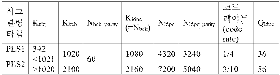
베이스밴드 프레임 (또는 BBFRAME): 하나의 FEC 인코딩 과정 (BCH 및 LDPC 인코딩)에 대한 입력을 형성하는 Kbch 비트의 집합Baseband Frame (or BBFRAME): A set of Kbch bits that form the input for one FEC encoding process (BCH and LDPC encoding).
셀(cell): OFDM 전송의 하나의 캐리어에 의해 전달되는 변조값Cell: modulation value carried by one carrier of an OFDM transmission
코딩 블록(coded block): PLS1 데이터의 LDPC 인코딩된 블록 또는 PLS2 데이터의 LDPC 인코딩된 블록들 중 하나Coded block: one of an LDPC encoded block of PLS1 data or an LDPC encoded block of PLS2 data
데이터 파이프(data pipe): 하나 또는 다수의 서비스 또는 서비스 컴포넌트를 전달할 수 있는 서비스 데이터 또는 관련된 메타데이터를 전달하는 물리 계층(physical layer)에서의 로지컬 채널Data pipe: a logical channel in the physical layer that carries service data or related metadata that can carry one or more services or service components
데이터 파이프 유닛(DPU, data pipe unit): 데이터 셀을 프레임에서의 데이터 파이프에 할당할 수 있는 기본 유닛Data pipe unit (DPU): A basic unit that can allocate data cells to data pipes in a frame
데이터 심볼(data symbol): 프리앰블 심볼이 아닌 프레임에서의 OFDM 심볼 (프레임 시그널링 심볼 및 프레임 엣지(edge) 심볼은 데이터 심볼에 포함된다.)Data symbol: OFDM symbol in a frame that is not a preamble symbol (frame signaling symbols and frame edge symbols are included in the data symbols)
DP_ID: 해당 8비트 필드는 SYSTEM_ID에 의해 식별된 시스템 내에서 데이터 파이프를 유일하게 식별한다.DP_ID: This 8-bit field uniquely identifies a data pipe within the system identified by SYSTEM_ID.
더미 셀(dummy cell): PLS (physical layer signalling) 시그널링, 데이터 파이프, 또는 보조 스트림을 위해 사용되지 않은 남아 있는 용량을 채우는 데 사용되는 의사 랜덤값을 전달하는 셀Dummy cell: A cell that carries a pseudo-random value used to fill the remaining unused capacity for physical layer signaling (PLS) signaling, data pipes, or auxiliary streams.
FAC (emergency alert channel, 비상 경보 채널): EAS 정보 데이터를 전달하는 프레임 중 일부Emergency alert channel (FAC): The part of a frame that carries EAS information data.
프레임(frame): 프리앰블로 시작해서 프레임 엣지 심볼로 종료되는 물리 계층(physical layer) 타임 슬롯Frame: A physical layer time slot starting with a preamble and ending with a frame edge symbol.
프레임 리피티션 유닛(frame repetition unit, 프레임 반복 단위): 슈퍼 프레임(super-frame)에서 8회 반복되는 FEF를 포함하는 동일한 또는 다른 피지컬 프로파일에 속하는 프레임의 집합Frame repetition unit: A set of frames belonging to the same or different physical profile that contains an FEF that is repeated eight times in a super-frame.
FIC (fast information channel, 고속 정보 채널): 서비스와 해당 베이스 데이터 파이프 사이에서의 매핑 정보를 전달하는 프레임에서 로지컬 채널Fast information channel (FIC): A logical channel in a frame that carries mapping information between a service and its base data pipe.
FECBLOCK: 데이터 파이프 데이터의 LDPC 인코딩된 비트의 집합FECBLOCK: set of LDPC encoded bits of data pipe data
FFT 사이즈: 기본 주기 T의 사이클로 표현된 액티브 심볼 주기 Ts와 동일한 특정 모드에 사용되는 명목상의 FFT 사이즈FFT size: The nominal FFT size used for a particular mode equal to the active symbol period Ts expressed in cycles of the fundamental period T.
프레임 시그널링 심볼(frame signaling symbol): PLS 데이터의 일부를 전달하는, FFT 사이즈, 가드 인터벌(guard interval), 및 스캐터(scattered) 파일럿 패턴의 특정 조합에서 프레임의 시작에서 사용되는 더 높은 파일럿 밀도를 갖는 OFDM 심볼Frame signaling symbol: The higher pilot density used at the start of a frame in a particular combination of FFT size, guard interval, and scattered pilot pattern, which carries a portion of the PLS data. Having OFDM symbol
프레임 엣지 심볼(frame edge symbol): FFT 사이즈, 가드 인터벌, 및 스캐터 파일럿 패턴의 특정 조합에서 프레임의 끝에서 사용되는 더 높은 파일럿 밀도를 갖는 OFDM 심볼Frame edge symbol: An OFDM symbol with a higher pilot density used at the end of the frame in a particular combination of FFT size, guard interval, and scatter pilot pattern.
프레임 그룹(frame-group): 슈퍼 프레임에서 동일한 피지컬 프로파일 타입을 갖는 모든 프레임의 집합Frame-group: set of all frames with the same physical profile type in a superframe
퓨쳐 익스텐션 프레임(future extention frame, 추후 확장 프레임): 프리앰블로 시작하는, 추후 확장에 사용될 수 있는 슈퍼 프레임 내에서 물리 계층(physical layer) 타임 슬롯Future extention frame: A physical layer time slot within a super frame that can be used for future expansion, starting with a preamble.
퓨처캐스트(futurecast) UTB 시스템: 입력이 하나 이상의 MPEG2-TS 또는 IP (Internet protocol) 또는 일반 스트림이고 출력이 RF 시그널인 제안된 물리 계층(physical layer) 방송 시스템Futurecast UTB system: A proposed physical layer broadcast system whose input is one or more MPEG2-TS or IP (Internet protocol) or generic streams and the output is an RF signal.
인풋 스트림(input stream, 입력 스트림): 시스템에 의해 최종 사용자에게 전달되는 서비스의 조화(ensemble)를 위한 데이터의 스트림Input stream: A stream of data for the coordination of services delivered to the end user by the system.
노멀(normal) 데이터 심볼: 프레임 시그널링 심볼 및 프레임 엣지 심볼을 제외한 데이터 심볼Normal data symbols: data symbols except frame signaling symbols and frame edge symbols
피지컬 프로파일(PHY profile): 해당하는 수신기가 구현해야 하는 모든 구조의 서브셋PHY profile: A subset of all structures that the corresponding receiver must implement
PLS: PLS1 및 PLS2로 구성된 물리 계층(physical layer) 시그널링 데이터PLS: physical layer signaling data consisting of PLS1 and PLS2
PLS1: PLS2를 디코딩하는 데 필요한 파라미터뿐만 아니라 시스템에 관한 기본 정보를 전달하는 고정된 사이즈, 코딩, 변조를 갖는 FSS (frame signalling symbol)로 전달되는 PLS 데이터의 첫 번째 집합PLS1: The first set of PLS data carried in a frame signaling symbol (FSS) with fixed size, coding, and modulation that conveys basic information about the system as well as the parameters needed to decode PLS2.
NOTE: PLS1 데이터는 프레임 그룹의 듀레이션(duration) 동안 일정하다.NOTE: PLS1 data is constant during the duration of the frame group.
PLS2: 데이터 파이프 및 시스템에 관한 더욱 상세한 PLS 데이터를 전달하는 FSS로 전송되는 PLS 데이터의 두 번째 집합PLS2: The second set of PLS data sent to the FSS carrying more detailed PLS data about data pipes and systems.
PLS2 다이나믹(dynamic, 동적) 데이터: 프레임마다 다이나믹(dynamic, 동적)으로 변화하는 PLS2 데이터PLS2 dynamic data: PLS2 data that changes dynamically from frame to frame
PLS2 스태틱(static, 정적) 데이터: 프레임 그룹의 듀레이션 동안 스태틱(static, 정적)인 PLS2 데이터PLS2 static data: PLS2 data that is static during the duration of a frame group
프리앰블 시그널링 데이터(preamble signaling data): 프리앰블 심볼에 의해 전달되고 시스템의 기본 모드를 확인하는 데 사용되는 시그널링 데이터Preamble signaling data: signaling data carried by the preamble symbol and used to identify the basic mode of the system
프리앰블 심볼(preamble symbol): 기본 PLS 데이터를 전달하고 프레임의 시작에 위치하는 고정된 길이의 파일럿 심볼Preamble symbol: a fixed length pilot symbol carrying basic PLS data and positioned at the beginning of a frame
NOTE: 프리앰블 심볼은 시스템 신호, 그 타이밍, 주파수 오프셋, 및 FFT 사이즈를 검출하기 위해 고속 초기 밴드 스캔에 주로 사용된다.NOTE: Preamble symbols are primarily used for fast initial band scans to detect system signals, their timings, frequency offsets, and FFT sizes.
추후 사용(future use)을 위해 리저브드(reserved): 현재 문서에서 정의되지 않지만 추후에 정의될 수 있음Reserved for future use: not defined in the current document, but may be defined later
슈퍼 프레임(superframe): 8개의 프레임 반복 단위의 집합Superframe: set of eight frame repeat units
타임 인터리빙 블록(time interleaving block, TI block): 타임 인터리버 메모리의 하나의 용도에 해당하는, 타임 인터리빙이 실행되는 셀의 집합Time interleaving block (TI block): A set of cells in which time interleaving is performed, corresponding to one use of time interleaver memory.
타임 인터리빙 그룹(time interleaving group, TI group): 정수, 다이나믹(dynamic, 동적)으로 변화하는 XFECBLOCK의 수로 이루어진, 특정 데이터 파이프에 대한 다이나믹(dynamic, 동적) 용량 할당이 실행되는 단위Time interleaving group (TI group): A unit in which dynamic capacity allocation is performed for a particular data pipe, consisting of an integer, the number of XFECBLOCKs that change dynamically.
NOTE: 타임 인터리빙 그룹은 하나의 프레임에 직접 매핑되거나 다수의 프레임에 매핑될 수 있다. 타임 인터리빙 그룹은 하나 이상의 타임 인터리빙 블록을 포함할 수 있다.NOTE: A time interleaving group can be directly mapped to one frame or mapped to multiple frames. The time interleaving group may include one or more time interleaving blocks.
타입 1 데이터 파이프(Type 1 DP): 모든 데이터 파이프가 프레임에 TDM (time division multiplexing) 방식으로 매핑되는 프레임의 데이터 파이프 Type 1 DP (Type 1 DP): A data pipe in a frame where all data pipes are mapped to frames in a time division multiplexing (TDM) manner
타입 2 데이터 파이프(Type 2 DP): 모든 데이터 파이프가 프레임에 FDM 방식으로 매핑되는 프레임의 데이터 파이프 Type 2 DPs: Types of data pipes in a frame where all data pipes are mapped to frames in an FDM fashion.
XFECBLOCK: 하나의 LDPC FECBLOCK의 모든 비트를 전달하는 Ncells 셀들의 집합XFECBLOCK: set of N cells cells carrying all the bits of one LDPC FECBLOCK
도 1은 본 발명의 일 실시예에 따른 차세대 방송 서비스에 대한 방송 신호 송신 장치의 구조를 나타낸다.1 shows a structure of a broadcast signal transmission apparatus for a next generation broadcast service according to an embodiment of the present invention.
본 발명의 일 실시예에 따른 차세대 방송 서비스에 대한 방송 신호 송신 장치는 인풋 포맷 블록 (Input Format block) (1000), BICM (bit interleaved coding & modulation) 블록(1010), 프레임 빌딩 블록 (Frame building block) (1020), OFDM (orthogonal frequency division multiplexing) 제너레이션 블록 (OFDM generation block)(1030), 및 시그널링 생성 블록(1040)을 포함할 수 있다. 방송 신호 송신 장치의 각 블록의 동작에 대해 설명한다.A broadcast signal transmission apparatus for a next generation broadcast service according to an embodiment of the present invention includes an input format block 1000, a bit interleaved coding & modulation (BICM) block 1010, and a frame building block 1020, orthogonal frequency division multiplexing (OFDM) generation block (OFDM generation block) 1030, and signaling generation block 1040. The operation of each block of the broadcast signal transmission apparatus will be described.
IP 스트림/패킷 및 MPEG2-TS은 주요 입력 포맷이고, 다른 스트림 타입은 일반 스트림으로 다루어진다. 이들 데이터 입력에 추가로, 관리 정보가 입력되어 각 입력 스트림에 대한 해당 대역폭의 스케줄링 및 할당을 제어한다. 하나 또는 다수의 TS 스트림, IP 스트림 및/또는 일반 스트림 입력이 동시에 허용된다.IP streams / packets and MPEG2-TS are the main input formats and other stream types are treated as general streams. In addition to these data inputs, management information is input to control the scheduling and allocation of the corresponding bandwidth for each input stream. One or multiple TS streams, IP streams and / or general stream inputs are allowed at the same time.
인풋 포맷 블록(1000)은 각각의 입력 스트림을 독립적인 코딩 및 변조가 적용되는 하나 또는 다수의 데이터 파이프로 디멀티플렉싱 할 수 있다. 데이터 파이프는 견고성(robustness) 제어를 위한 기본 단위이며, 이는 QoS (Quality of Service)에 영향을 미친다. 하나 또는 다수의 서비스 또는 서비스 컴포넌트가 하나의 데이터 파이프에 의해 전달될 수 있다. 인풋 포맷 블록(1000)의 자세한 동작은 후술한다.The input format block 1000 can demultiplex each input stream into one or multiple data pipes to which independent coding and modulation is applied. The data pipe is the basic unit for controlling robustness, which affects the quality of service (QoS). One or multiple services or service components may be delivered by one data pipe. Detailed operations of the input format block 1000 will be described later.
데이터 파이프는 하나 또는 다수의 서비스 또는 서비스 컴포넌트를 전달할 수 있는 서비스 데이터 또는 관련 메타데이터를 전달하는 물리 계층(physical layer)에서의 로지컬 채널이다.A data pipe is a logical channel at the physical layer that carries service data or related metadata that can carry one or multiple services or service components.
또한, 데이터 파이프 유닛은 하나의 프레임에서 데이터 셀을 데이터 파이프에 할당하기 위한 기본 유닛이다.In addition, the data pipe unit is a basic unit for allocating data cells to data pipes in one frame.
인풋 포맷 블록(1000)에서, 패리티(parity) 데이터는 에러 정정을 위해 추가되고, 인코딩된 비트 스트림은 복소수값 컨스텔레이션 심볼에 매핑된다. 해당 심볼은 해당 데이터 파이프에 사용되는 특정 인터리빙 깊이에 걸쳐 인터리빙 된다. 어드벤스 프로파일에 있어서, BICM 블록(1010)에서 MIMO 인코딩이 실행되고 추가 데이터 경로가 MIMO 전송을 위해 출력에 추가된다. BICM 블록(1010)의 자세한 동작은 후술한다.In input format block 1000, parity data is added for error correction and the encoded bit stream is mapped to a complex value constellation symbol. The symbols are interleaved over the specific interleaving depth used for that data pipe. For the advanced profile, MIMO encoding is performed at BICM block 1010 and additional data paths are added to the output for MIMO transmission. Detailed operations of the BICM block 1010 will be described later.
프레임 빌딩 블록(1020)은 하나의 프레임 내에서 입력 데이터 파이프의 데이터 셀을 OFDM 실볼로 매핑할 수 있다. 매핑 후, 주파수 영역 다이버시티를 위해, 특히 주파수 선택적 페이딩 채널을 방지하기 위해 주파수 인터리빙이 이용된다. 프레임 빌딩 블록(1020)의 자세한 동작은 후술한다.The frame building block 1020 may map data cells of an input data pipe to OFDM solid balls within one frame. After mapping, frequency interleaving is used for frequency domain diversity, in particular to prevent frequency selective fading channels. Detailed operations of the frame building block 1020 will be described later.
프리앰블을 각 프레임의 시작에 삽입한 후, OFDM 제너레이션 블록(1030)은 사이클릭 프리픽스(cyclic prefix)을 가드 인터벌로 갖는 기존의 OFDM 변조를 적용할 수 있다. 안테나 스페이스 다이버시티를 위해, 분산된(distributed) MISO 방식이 송신기에 걸쳐 적용된다. 또한, PAPR (peak-to-average power ratio) 방식이 시간 영역에서 실행된다. 유연한 네트워크 방식을 위해, 해당 제안은 다양한 FFT 사이즈, 가드 인터벌 길이, 해당 파일럿 패턴의 집합을 제공한다. OFDM 제너레이션 블록(1030)의 자세한 동작은 후술한다.After inserting the preamble at the beginning of each frame, the OFDM generation block 1030 can apply existing OFDM modulation having a cyclic prefix as the guard interval. For antenna space diversity, a distributed MISO scheme is applied across the transmitter. In addition, a peak-to-average power ratio (PAPR) scheme is implemented in the time domain. For a flexible network approach, the proposal provides a variety of FFT sizes, guard interval lengths, and sets of corresponding pilot patterns. Detailed operations of the OFDM generation block 1030 will be described later.
시그널링 생성 블록(1040)은 각 기능 블록의 동작에 사용되는 물리 계층(physical layer) 시그널링 정보를 생성할 수 있다. 해당 시그널링 정보는 또한 관심 있는 서비스가 수신기 측에서 적절히 복구되도록 전송된다. 시그널링 생성 블록(1040)의 자세한 동작은 후술한다.The signaling generation block 1040 may generate physical layer signaling information used for the operation of each functional block. The signaling information is also transmitted such that the service of interest is properly recovered at the receiver side. Detailed operations of the signaling generation block 1040 will be described later.
도 2, 3, 4는 본 발명의 실시예에 따른 인풋 포맷 블록(1000)을 나타낸다. 각 도면에 대해 설명한다.2, 3, and 4 illustrate an input format block 1000 according to an embodiment of the present invention. Each drawing is demonstrated.
도 2는 본 발명의 일 실시예에 따른 인풋 포맷 블록을 나타낸다. 도 2는 입력 신호가 단일 입력 스트림(single input stream)일 때의 인풋 포맷 블록을 나타낸다.2 illustrates an input format block according to an embodiment of the present invention. 2 shows an input format block when the input signal is a single input stream.
도 2에 도시된 인풋 포맷 블록은 도 1을 참조하여 설명한 인풋 포맷 블록(1000)의 일 실시예에 해당한다.The input format block illustrated in FIG. 2 corresponds to an embodiment of the input format block 1000 described with reference to FIG. 1.
물리 계층(physical layer)으로의 입력은 하나 또는 다수의 데이터 스트림으로 구성될 수 있다. 각각의 데이터 스트림은 하나의 데이터 파이프에 의해 전달된다. 모드 어댑테이션(mode adaptaion, 모드 적응) 모듈은 입력되는 데이터 스트림을 BBF (baseband frame)의 데이터 필드로 슬라이스한다. 해당 시스템은 세 가지 종류의 입력 데이터 스트림, 즉 MPEG2-TS, IP, GS (generic stream)을 지원한다. MPEG2-TS는 첫 번째 바이트가 동기 바이트(0x47)인 고정된 길이(188 바이트)의 패킷을 특징으로 한다. IP 스트림은 IP 패킷 헤더 내에서 시그널링 되는 가변 길이 IP 데이터그램 패킷으로 구성된다. 해당 시스템은 IP 스트림에 대해 IPv4와 IPv6을 모두 지원한다. GS는 캡슐화 패킷 헤더 내에서 시그널링되는 가변 길이 패킷 또는 일정 길이 패킷으로 구성될 수 있다.Input to the physical layer may consist of one or multiple data streams. Each data stream is carried by one data pipe. The mode adaptation module slices the input data stream into a data field of a baseband frame (BBF). The system supports three types of input data streams: MPEG2-TS, IP, and GS (generic stream). MPEG2-TS features a fixed length (188 bytes) packet where the first byte is a sync byte (0x47). An IP stream consists of variable length IP datagram packets signaled in IP packet headers. The system supports both IPv4 and IPv6 for IP streams. The GS may consist of variable length packets or constant length packets signaled in the encapsulation packet header.
(a)는 신호 데이터 파이프에 대한 모드 어댑테이션(mode adaptaion, 모드 적응) 블록(2000) 및 스트림 어댑테이션(stream adaptation, 스트림 적응)(2010)을 나타내고, (b)는 PLS 데이터를 생성 및 처리하기 위한 PLS 생성 블록(2020) 및 PLS 스크램블러(2030)를 나타낸다. 각 블록의 동작에 대해 설명한다.(a) shows a mode adaptation block 2000 and a stream adaptation (stream adaptation) 2010 for a signal data pipe, and (b) shows a method for generating and processing PLS data. PLS generation block 2020 and PLS scrambler 2030 are shown. The operation of each block will be described.
입력 스트림 스플리터는 입력된 TS, IP, GS 스트림을 다수의 서비스 또는 서비스 컴포넌트(오디오, 비디오 등) 스트림으로 분할한다. 모드 어댑테이션(mode adaptaion, 모드 적응) 모듈(2010)은 CRC 인코더, BB (baseband) 프레임 슬라이서, 및 BB 프레임 헤더 삽입 블록으로 구성된다.The input stream splitter splits the input TS, IP, GS streams into multiple service or service component (audio, video, etc.) streams. The mode adaptation module 2010 is composed of a CRC encoder, a baseband (BB) frame slicer, and a BB frame header insertion block.
CRC 인코더는 유저 패킷 (user packet, UP)레벨에서의 에러 검출을 위한 세 종류의 CRC 인코딩, 즉 CRC-8, CRC-16, CRC-32를 제공한다. 산출된 CRC 바이트는 UP 뒤에 첨부된다. CRC-8은 TS 스트림에 사용되고, CRC-32는 IP 스트림에 사용된다. GS 스트림이 CRC 인코딩을 제공하지 않으면, 제안된 CRC 인코딩이 적용되어야 한다.The CRC encoder provides three types of CRC encoding, CRC-8, CRC-16, and CRC-32, for error detection at the user packet (UP) level. The calculated CRC byte is appended after the UP. CRC-8 is used for the TS stream, and CRC-32 is used for the IP stream. If the GS stream does not provide CRC encoding, then the proposed CRC encoding should be applied.
BB 프레임 슬라이서는 입력을 내부 로지컬 비트 포맷에 매핑한다. 첫 번째 수신 비트는 MSB라고 정의한다. BB 프레임 슬라이서는 가용 데이터 필드 용량과 동일한 수의 입력 비트를 할당한다. BBF 페이로드와 동일한 수의 입력 비트를 할당하기 위해, UP 스트림이 BBF의 데이터 필드에 맞게 슬라이스된다.The BB Frame Slicer maps the input to an internal logical bit format. The first receive bit is defined as MSB. The BB frame slicer allocates the same number of input bits as the available data field capacity. In order to allocate the same number of input bits as the BBF payload, the UP stream is sliced to fit the data field of the BBF.
BB 프레임 헤더 삽입 블록은 2바이트의 고정된 길이의 BBF 헤더를 BB 프레임의 앞에 삽입할 수 있다. BBF 헤더는 STUFFI (1비트), SYNCD (13비트), 및 RFU (2비트)로 구성된다. 고정된 2바이트 BBF 헤더뿐만 아니라, BBF는 2바이트 BBF 헤더 끝에 확장 필드(1 또는 3바이트)를 가질 수 있다.The BB frame header insertion block can insert a 2 bytes fixed length BBF header before the BB frame. The BBF header consists of STUFFI (1 bit), SYNCD (13 bit), and RFU (2 bit). In addition to the fixed 2-byte BBF header, the BBF may have an extension field (1 or 3 bytes) at the end of the 2-byte BBF header.
스트림 어댑테이션(stream adaptation, 스트림 적응)(2010)은 스터핑(stuffing) 삽입 블록 및 BB 스크램블러로 구성된다. 스터핑 삽입 블록은 스터핑 필드를 BB 프레임의 페이로드에 삽입할 수 있다. 스트림 어댑테이션(stream adaptation, 스트림 적응)에 대한 입력 데이터가 BB 프레임을 채우기에 충분하면, STUFFI는 0으로 설정되고, BBF는 스터핑 필드를 갖지 않는다. 그렇지 않으면, STUFFI는 1로 설정되고, 스터핑 필드는 BBF 헤더 직후에 삽입된다. 스터핑 필드는 2바이트의 스터핑 필드 헤더 및 가변 사이즈의 스터핑 데이터를 포함한다. Stream adaptation 2010 consists of a stuffing insertion block and a BB scrambler. The stuffing insertion block may insert the stuffing field into the payload of the BB frame. If the input data for the stream adaptation is sufficient to fill the BB frame, STUFFI is set to 0, and the BBF has no stuffing field. Otherwise, STUFFI is set to 1 and the stuffing field is inserted immediately after the BBF header. The stuffing field includes a 2-byte stuffing field header and variable sized stuffing data.
BB 스크램블러는 에너지 분산을 위해 완전한 BBF를 스크램블링한다. 스크램블링 시퀀스는 BBF와 동기화된다. 스크램블링 시퀀스는 피드백 시프트 레지스터에 의해 생성된다.The BB scrambler scrambles the complete BBF for energy dissipation. The scrambling sequence is synchronized with the BBF. The scrambling sequence is generated by the feedback shift register.
PLS 생성 블록(2020)은 PLS 데이터를 생성할 수 있다. PLS는 수신기에서 피지컬 레이어(physical layer) 데이터 파이프에 접속할 수 있는 수단을 제공한다. PLS 데이터는 PLS1 데이터 및 PLS2 데이터로 구성된다.The PLS generation block 2020 may generate PLS data. PLS provides a means by which a receiver can connect to a physical layer data pipe. PLS data consists of PLS1 data and PLS2 data.
PLS1 데이터는 PLS2 데이터를 디코딩하는 데 필요한 파라미터뿐만 아니라 시스템에 관한 기본 정보를 전달하는 고정된 사이즈, 코딩, 변조를 갖는 프레임에서 FSS로 전달되는 PLS 데이터의 첫 번째 집합이다. PLS1 데이터는 PLS2 데이터의 수신 및 디코딩을 가능하게 하는 데 요구되는 파라미터를 포함하는 기본 송신 파라미터를 제공한다. 또한, PLS1 데이터는 프레임 그룹의 듀레이션 동안 일정하다.PLS1 data is the first set of PLS data delivered to the FSS in frames with fixed size, coding, and modulation that convey basic information about the system as well as the parameters needed to decode the PLS2 data. PLS1 data provides basic transmission parameters including the parameters required to enable reception and decoding of PLS2 data. In addition, the PLS1 data is constant during the duration of the frame group.
PLS2 데이터는 데이터 파이프 및 시스템에 관한 더욱 상세한 PLS 데이터를 전달하는 FSS로 전송되는 PLS 데이터의 두 번째 집합이다. PLS2는 수신기가 원하는 데이터 파이프를 디코딩하는 데 충분한 정보를 제공하는 파라미터를 포함한다. PLS2 시그널링은 PLS2 스태틱(static, 정적) 데이터(PLS2-STAT 데이터) 및 PLS2 다이나믹(dynamic, 동적) 데이터(PLS2-DYN 데이터)의 두 종류의 파라미터로 더 구성된다. PLS2 스태틱(static, 정적) 데이터는 프레임 그룹의 듀레이션 동안 스태틱(static, 정적)인 PLS2 데이터이고, PLS2 다이나믹(dynamic, 동적) 데이터는 프레임마다 다이나믹(dynamic, 동적)으로 변화하는 PLS2 데이터이다.PLS2 data is the second set of PLS data sent to the FSS that carries more detailed PLS data about the data pipes and systems. PLS2 contains parameters that provide enough information for the receiver to decode the desired data pipe. PLS2 signaling further consists of two types of parameters: PLS2 static data (PLS2-STAT data) and PLS2 dynamic data (PLS2-DYN data). PLS2 static data is PLS2 data that is static during the duration of a frame group, and PLS2 dynamic data is PLS2 data that changes dynamically from frame to frame.
PLS 데이터에 대한 자세한 내용은 후술한다.Details of the PLS data will be described later.
PLS 스크램블러(2030)는 에너지 분산을 위해 생성된 PLS 데이터를 스크램블링 할 수 있다.The PLS scrambler 2030 may scramble PLS data generated for energy distribution.
전술한 블록은 생략될 수도 있고 유사 또는 동일 기능을 갖는 블록에 의해 대체될 수도 있다.The aforementioned blocks may be omitted or may be replaced by blocks having similar or identical functions.
도 3은 본 발명의 다른 일 실시예에 따른 인풋 포맷 블록을 나타낸다.3 illustrates an input format block according to another embodiment of the present invention.
도 3에 도시된 인풋 포맷 블록은 도 1을 참조하여 설명한 인풋 포맷 블록(1000)의 일 실시예에 해당한다.The input format block illustrated in FIG. 3 corresponds to an embodiment of the input format block 1000 described with reference to FIG. 1.
도 3은 입력 신호가 멀티 인풋 스트림(multi input stream, 다수의 입력 스트림)에 해당하는 경우 인풋 포맷 블록의 모드 어댑테이션(mode adaptaion, 모드 적응) 블록을 나타낸다.FIG. 3 illustrates a mode adaptation block of an input format block when the input signal corresponds to a multi input stream.
멀티 인풋 스트림(multi input stream, 다수의 입력 스트림)을 처리하기 위한 인풋 포맷 블록의 모드 어댑테이션(mode adaptaion, 모드 적응) 블록은 다수 입력 스트림을 독립적으로 처리할 수 있다.A mode adaptation block of an input format block for processing multi input streams may independently process multiple input streams.
도 3을 참조하면, 멀티 인풋 스트림(multi input stream, 다수의 입력 스트림)을 각각 처리하기 위한 모드 어댑테이션(mode adaptaion, 모드 적응) 블록은 인풋 스트림 스플리터 (input stream splitter) (3000), 인풋 스트림 싱크로나이저 (input stream synchronizer) (3010), 컴펜세이팅 딜레이(compensatin delay, 보상 지연) 블록(3020), 널 패킷 딜리션 블록 (null packet deletion block) (3030), 헤더 컴프레션 블록 (header compression block) (3040), CRC 인코더 (CRC encoder) (3050), BB 프레임 슬라이서(BB frame slicer) (3060), 및 BB 헤더 삽입 블록 (BB header insertion block) (3070)을 포함할 수 있다. 모드 어댑테이션(mode adaptaion, 모드 적응) 블록의 각 블록에 대해 설명한다.Referring to FIG. 3, a mode adaptation block for processing a multi input stream may be an input stream splitter 3000 or an input stream synchro. Input stream synchronizer (3010), compensating delay block (3020), null packet deletion block (3030), header compression block ( 3040, a CRC encoder 3050, a BB frame slicer 3060, and a BB header insertion block 3070. Each block of the mode adaptation block will be described.
CRC 인코더(3050), BB 프레임 슬라이서(3060), 및 BB 헤더 삽입 블록(3070)의 동작은 도 2를 참조하여 설명한 CRC 인코더, BB 프레임 슬라이서, 및 BB 헤더 삽입 블록의 동작에 해당하므로, 그 설명은 생략한다.Operations of the CRC encoder 3050, the BB frame slicer 3060, and the BB header insertion block 3070 correspond to the operations of the CRC encoder, the BB frame slicer, and the BB header insertion block described with reference to FIG. Is omitted.
인풋 스트림 스플리터(3000)는 입력된 TS, IP, GS 스트림을 다수의 서비스 또는 서비스 컴포넌트(오디오, 비디오 등) 스트림으로 분할한다.The input stream splitter 3000 splits the input TS, IP, and GS streams into a plurality of service or service component (audio, video, etc.) streams.
인풋 스트림 싱크로나이저(3010)는 ISSY라 불릴 수 있다. ISSY는 어떠한 입력 데이터 포맷에 대해서도 CBR (constant bit rate) 및 일정한 종단간 전송(end-to-end transmission) 지연을 보장하는 적합한 수단을 제공할 수 있다. ISSY는 TS를 전달하는 다수의 데이터 파이프의 경우에 항상 이용되고, GS 스트림을 전달하는 다수의 데이터 파이프에 선택적으로 이용된다.The input stream synchronizer 3010 may be called ISSY. ISSY can provide suitable means to ensure constant bit rate (CBR) and constant end-to-end transmission delay for any input data format. ISSY is always used in the case of multiple data pipes carrying TS, and optionally in multiple data pipes carrying GS streams.
컴펜세이팅 딜레이(compensatin delay, 보상 지연) 블록(3020)은 수신기에서 추가로 메모리를 필요로 하지 않고 TS 패킷 재결합 메커니즘을 허용하기 위해 ISSY 정보의 삽입에 뒤따르는 분할된 TS 패킷 스트림을 지연시킬 수 있다.Compensating delay block 3020 may delay the split TS packet stream following the insertion of ISSY information to allow TS packet recombination mechanisms without requiring additional memory at the receiver. have.
널 패킷 딜리션 블록(3030)은 TS 입력 스트림 경우에만 사용된다. 일부 TS 입력 스트림 또는 분할된 TS 스트림은 VBR (variable bit-rate) 서비스를 CBR TS 스트림에 수용하기 위해 존재하는 많은 수의 널 패킷을 가질 수 있다. 이 경우, 불필요한 전송 오버헤드를 피하기 위해, 널 패킷은 확인되어 전송되지 않을 수 있다. 수신기에서, 제거된 널 패킷은 전송에 삽입된 DNP(deleted null-packet, 삭제된 널 패킷) 카운터를 참조하여 원래 존재했던 정확한 장소에 재삽입될 수 있어, CBR이 보장되고 타임 스탬프(PCR) 갱신의 필요가 없어진다.The null packet deletion block 3030 is used only for the TS input stream. Some TS input streams or split TS streams may have a large number of null packets present to accommodate variable bit-rate (VBR) services in the CBR TS stream. In this case, to avoid unnecessary transmission overhead, null packets may be acknowledged and not transmitted. At the receiver, the discarded null packet can be reinserted in the exact place it originally existed with reference to the deleted null-packet (DNP) counter inserted in the transmission, ensuring CBR and time stamp (PCR) updates. There is no need.
헤더 컴프레션 블록(3040)은 TS 또는 IP 입력 스트림에 대한 전송 효율을 증가시키기 위해 패킷 헤더 압축을 제공할 수 있다. 수신기는 헤더의 특정 부분에 대한 선험적인(a priori) 정보를 가질 수 있기 때문에, 이 알려진 정보(known information)는 송신기에서 삭제될 수 있다.The header compression block 3040 can provide packet header compression to increase transmission efficiency for the TS or IP input stream. Since the receiver may have a priori information for a particular portion of the header, this known information may be deleted at the transmitter.
TS에 대해, 수신기는 동기 바이트 구성(0x47) 및 패킷 길이(188 바이트)에 관한 선험적인 정보를 가질 수 있다. 입력된 TS가 하나의 PID만을 갖는 콘텐트를 전달하면, 즉, 하나의 서비스 컴포넌트(비디오, 오디오 등) 또는 서비스 서브 컴포넌트(SVC 베이스 레이어, SVC 인헨스먼트 레이어, MVC 베이스 뷰, 또는 MVC 의존 뷰)에 대해서만, TS 패킷 헤더 압축이 TS에 (선택적으로) 적용될 수 있다. TS 패킷 헤더 압축은 입력 스트림이 IP 스트림인 경우 선택적으로 사용된다. 상기 블록은 생략되거나 유사 또는 동일 기능을 갖는 블록으로 대체될 수 있다.For the TS, the receiver may have a priori information about the sync byte configuration (0x47) and the packet length (188 bytes). If the input TS delivers content with only one PID, that is, one service component (video, audio, etc.) or service subcomponent (SVC base layer, SVC enhancement layer, MVC base view, or MVC dependent view) Only, TS packet header compression may (optionally) be applied to the TS. TS packet header compression is optionally used when the input stream is an IP stream. The block may be omitted or replaced with a block having similar or identical functions.
도 4는 본 발명의 다른 실시예에 따른 인풋 포맷 블록을 나타낸다.4 illustrates an input format block according to another embodiment of the present invention.
도 4에 도시된 인풋 포맷 블록은 도 1을 참조하여 설명한 인풋 포맷 블록(1000)의 일 실시예에 해당한다.The input format block illustrated in FIG. 4 corresponds to an embodiment of the input format block 1000 described with reference to FIG. 1.
도 4는 입력 신호가 멀티 인풋 스트림(multi input stream, 다수의 입력 스트림)에 해당하는 경우 인풋 포맷 블록의 스트림 어댑테이션(stream adaptation, 스트림 적응) 블록을 나타낸다.FIG. 4 illustrates a stream adaptation block of an input format block when the input signal corresponds to a multi input stream.
도 4를 참조하면, 멀티 인풋 스트림(multi input stream, 다수의 입력 스트림)을 각각 처리하기 위한 모드 어댑테이션(mode adaptaion, 모드 적응) 블록은 스케줄러(4000), 1-프레임 딜레이(delay) 블록(4010), 스터핑 삽입 블록(4020), 인 밴드(In-band) 시그널링 블록(4030), BB 프레임 스크램블러(4040), PLS 생성 블록(4050), PLS 스크램블러(4060)를 포함할 수 있다. 스트림 어댑테이션(stream adaptation, 스트림 적응) 블록의 각 블록에 대해 설명한다.Referring to FIG. 4, a mode adaptation block for processing a multi input stream (multiple input stream), respectively, includes a scheduler 4000 and a 1-frame delay block 4010. ), A stuffing insertion block 4020, an in-band signaling block 4030, a BB frame scrambler 4040, a PLS generation block 4050, and a PLS scrambler 4060. Each block of the stream adaptation block will be described.
스터핑 삽입 블록(4020), BB 프레임 스크램블러(4040), PLS 생성 블록(4050), PLS 스크램블러(4060)의 동작은 도 2를 참조하여 설명한 스터핑 삽입 블록, BB 스크램블러, PLS 생성 블록, PLS 스크램블러(4060)의 동작에 해당하므로 그 설명은 생략한다.The operations of the stuffing insertion block 4020, the BB frame scrambler 4040, the PLS generation block 4050, and the PLS scrambler 4060 are described with reference to FIG. 2. ), So its description is omitted.
스케줄러(4000)는 각 데이터 파이프의 FECBLOCK의 양으로부터 전체 프레임에 걸쳐 전체의 셀 할당을 결정할 수 있다. PLS, EAC 및 FIC에 대한 할당을 포함해서, 스케줄러는 프레임의 FSS의 PLS 셀 또는 인 밴드(In-band) 시그널링으로 전송되는 PLS2-DYN 데이터의 값을 생성한다. FECBLOCK, EAC, FIC에 대한 상세한 내용은 후술한다.The scheduler 4000 may determine the overall cell allocation over the entire frame from the amount of FECBLOCK of each data pipe. Including the assignments for PLS, EAC and FIC, the scheduler generates values of PLS2-DYN data transmitted in PLS cells or in-band signaling of the FSS of the frame. Details of FECBLOCK, EAC, and FIC will be described later.
1-프레임 딜레이(delay) 블록(4010)은 다음 프레임에 관한 스케줄링 정보가 데이터 파이프에 삽입될 인 밴드(In-band) 시그널링 정보에 관한 현 프레임을 통해 전송될 수 있도록 입력 데이터를 하나의 전송 프레임만큼 지연시킬 수 있다.The 1-frame delay block 4010 transmits input data to one transmission frame so that scheduling information about the next frame can be transmitted through the current frame regarding the in-band signaling information to be inserted into the data pipe. You can delay it.
인 밴드(In-band) 시그널링 블록(4030)은 PLS2 데이터의 지연되지 않은 부분을 프레임의 데이터 파이프에 삽입할 수 있다.In-band signaling block 4030 may insert the non-delayed portion of the PLS2 data into the data pipe of the frame.
전술한 블록은 생략되거나 유사 또는 동일 기능을 갖는 블록으로 대체될 수 있다.The aforementioned blocks may be omitted or replaced with blocks having similar or identical functions.
도 5는 본 발명의 일 실시예에 따른 BICM 블록을 나타낸다.5 illustrates a BICM block according to an embodiment of the present invention.
도 5에 도시된 BICM 블록은 도 1을 참조하여 설명한 BICM 블록(1010)의 일 실시예에 해당한다.The BICM block illustrated in FIG. 5 corresponds to an embodiment of the BICM block 1010 described with reference to FIG. 1.
전술한 바와 같이, 본 발명의 일 실시예에 따른 차세대 방송 서비스에 대한 방송 신호 송신 장치는 지상파 방송 서비스, 모바일 방송 서비스, UHDTV 서비스 등을 제공할 수 있다.As described above, the broadcast signal transmission apparatus for the next generation broadcast service according to an embodiment of the present invention may provide a terrestrial broadcast service, a mobile broadcast service, a UHDTV service, and the like.
QoS가 본 발명의 일 실시예에 따른 차세대 방송 서비스에 대한 방송 신호 송신 장치에 의해 제공되는 서비스의 특성에 의존하므로, 각각의 서비스에 해당하는 데이터는 서로 다른 방식을 통해 처리되어야 한다. 따라서, 본 발명의 일 실시예에 따른 BICM 블록은 SISO, MISO, MIMO 방식을 각각의 데이터 경로에 해당하는 데이터 파이프에 독립적으로 적용함으로써 각데이터 파이프를 독립적으로 처리할 수 있다. 결과적으로, 본 발명의 일 실시예에 따른 차세대 방송 서비스에 대한 방송 신호 송신 장치는 각각의 데이터 파이프를 통해 전송되는 각 서비스 또는 서비스 컴포넌트에 대한 QoS를 조절할 수 있다.Since QoS depends on the characteristics of the service provided by the broadcast signal transmission apparatus for the next generation broadcast service according to an embodiment of the present invention, data corresponding to each service should be processed in different ways. Accordingly, the BICM block according to an embodiment of the present invention can independently process each data pipe by independently applying the SISO, MISO, and MIMO schemes to the data pipes corresponding to the respective data paths. As a result, the apparatus for transmitting broadcast signals for the next generation broadcast service according to an embodiment of the present invention may adjust QoS for each service or service component transmitted through each data pipe.
(a)는 베이스 프로파일 및 핸드헬드 프로파일에 의해 공유되는 BICM 블록을 나타내고, (b)는 어드벤스 프로파일의 BICM 블록을 나타낸다.(a) shows the BICM block shared by the base profile and the handheld profile, and (b) shows the BICM block of the advanced profile.
베이스 프로파일 및 핸드헬드 프로파일에 의해 공유되는 BICM 블록 및 어드벤스 프로파일의 BICM 블록은 각각의 데이터 파이프를 처리하기 위한 복수의 처리 블록을 포함할 수 있다.The BICM block shared by the base profile and the handheld profile and the BICM block of the advanced profile may include a plurality of processing blocks for processing each data pipe.
베이스 프로파일 및 핸드헬드 프로파일에 대한 BICM 블록 및 어드벤스 프로파일에 대한 BICM 블록의 각각의 처리 블록에 대해 설명한다.Each processing block of the BICM block for the base profile and the handheld profile and the BICM block for the advanced profile will be described.
베이스 프로파일 및 핸드헬드 프로파일에 대한 BICM 블록의 처리 블록(5000)은 데이터 FEC 인코더(5010), 비트 인터리버(5020), 컨스텔레이션 매퍼(mapper)(5030), SSD (signal space diversity) 인코딩 블록(5040), 타임 인터리버(5050)를 포함할 수 있다.The processing block 5000 of the BICM block for the base profile and the handheld profile includes a data FEC encoder 5010, a bit interleaver 5020, a constellation mapper 5030, a signal space diversity (SSD) encoding block ( 5040, and a time interleaver 5050.
데이터 FEC 인코더(5010)는 외부 코딩(BCH) 및 내부 코딩(LDPC)을 이용하여 FECBLOCK 절차를 생성하기 위해 입력 BBF에 FEC 인코딩을 실행한다. 외부 코딩(BCH)은 선택적인 코딩 방법이다. 데이터 FEC 인코더(5010)의 구체적인 동작에 대해서는 후술한다.The data FEC encoder 5010 performs FEC encoding on the input BBF to generate the FECBLOCK procedure using outer coding (BCH) and inner coding (LDPC). Outer coding (BCH) is an optional coding method. The detailed operation of the data FEC encoder 5010 will be described later.
비트 인터리버(5020)는 효율적으로 실현 가능한 구조를 제공하면서 데이터 FEC 인코더(5010)의 출력을 인터리빙하여 LDPC 코드 및 변조 방식의 조합으로 최적화된 성능을 달성할 수 있다. 비트 인터리버(5020)의 구체적인 동작에 대해서는 후술한다.The bit interleaver 5020 may interleave the output of the data FEC encoder 5010 while providing a structure that can be efficiently realized to achieve optimized performance by a combination of LDPC codes and modulation schemes. The detailed operation of the bit interleaver 5020 will be described later.
컨스텔레이션 매퍼(5030)는 QPSK, QAM-16, 불균일 QAM (NUQ-64, NUQ-256, NUQ-1024) 또는 불균일 컨스텔레이션 (NUC-16, NUC-64, NUC-256, NUC-1024)을 이용해서 베이스 및 핸드헬드 프로파일에서 비트 인터리버(5020)로부터의 각각의 셀 워드를 변조하거나 어드벤스 프로파일에서 셀 워드 디멀티플렉서(5010-1)로부터의 셀 워드를 변조하여 파워가 정규화된 컨스텔레이션 포인트 el을 제공할 수 있다. 해당 컨스텔레이션 매핑은 데이터 파이프에 대해서만 적용된다. NUQ가 임의의 형태를 갖는 반면, QAM-16 및 NUQ는 정사각형 모양을 갖는 것이 관찰된다. 각각의 컨스텔레이션이 90도의 배수만큼 회전되면, 회전된 컨스텔레이션은 원래의 것과 정확히 겹쳐진다. 회전 대칭 특성으로 인해 실수 및 허수 컴포넌트의 용량 및 평균 파워가 서로 동일해진다. NUQ 및 NUC는 모두 각 코드 레이트(code rate)에 대해 특별히 정의되고, 사용되는 특정 하나는 PLS2 데이터에 보관된 파라미터 DP_MOD에 의해 시그널링 된다. Constellation mapper 5030 can be QPSK, QAM-16, non-uniform QAM (NUQ-64, NUQ-256, NUQ-1024) or non-uniform constellation (NUC-16, NUC-64, NUC-256, NUC-1024) A constellation point whose power is normalized by modulating each cell word from the bit interleaver 5020 in the base and handheld profiles or the cell word from the cell word demultiplexer 5010-1 in the advanced profile. e l can be provided. The constellation mapping applies only to data pipes. It is observed that NUQ has any shape, while QAM-16 and NUQ have a square shape. If each constellation is rotated by a multiple of 90 degrees, the rotated constellation overlaps exactly with the original. Due to the rotational symmetry characteristic, the real and imaginary components have the same capacity and average power. Both NUQ and NUC are specifically defined for each code rate, and the particular one used is signaled by the parameter DP_MOD stored in the PLS2 data.
SSD 인코딩 블록(5040)은 2차원, 3차원, 4차원에서 셀을 프리코딩하여, 어려운 페이딩 조건에서 수신 견고성(robustness)을 증가시킬 수 있다.The SSD encoding block 5040 may pre-code cells in two, three, and four dimensions, thereby increasing reception robustness in difficult fading conditions.
타임 인터리버(5050)는 데이터 파이프 레벨에서 동작할 수 있다. 타임 인터리빙의 파라미터는 각각의 데이터 파이프에 대해 다르게 설정될 수 있다. 타임 인터리버(5050)의 구체적인 동작에 관해서는 후술한다.The time interleaver 5050 may operate at the data pipe level. The parameters of time interleaving can be set differently for each data pipe. The specific operation of the time interleaver 5050 will be described later.
어드벤스 프로파일에 대한 BICM 블록의 처리 블록(5000-1)은 데이터 FEC 인코더, 비트 인터리버, 컨스텔레이션 매퍼, 및 타임 인터리버를 포함할 수 있다.The processing block 5000-1 of the BICM block for the advanced profile may include a data FEC encoder, a bit interleaver, a constellation mapper, and a time interleaver.
단, 처리 블록(5000-1)은 셀 워드 디멀티플렉서(5010-1) 및 MIMO 인코딩 블록(5020-1)을 더 포함한다는 점에서 처리 블록(5000)과 구별된다.However, the processing block 5000-1 is distinguished from the processing block 5000 in that it further includes a cell word demultiplexer 5010-1 and a MIMO encoding block 5020-1.
또한, 처리 블록(5000-1)에서의 데이터 FEC 인코더, 비트 인터리버, 컨스텔레이션 매퍼, 타임 인터리버의 동작은 전술한 데이터 FEC 인코더(5010), 비트 인터리버(5020), 컨스텔레이션 매퍼(5030), 타임 인터리버(5050)의 동작에 해당하므로, 그 설명은 생략한다.In addition, operations of the data FEC encoder, the bit interleaver, the constellation mapper, and the time interleaver in the processing block 5000-1 may be performed by the data FEC encoder 5010, the bit interleaver 5020, and the constellation mapper 5030. Since this corresponds to the operation of the time interleaver 5050, the description thereof will be omitted.
셀 워드 디멀티플렉서(5010-1)는 어드벤스 프로파일의 데이터 파이프가 MIMO 처리를 위해 단일 셀 워드 스트림을 이중 셀 워드 스트림으로 분리하는 데 사용된다. 셀 워드 디멀티플렉서(5010-1)의 구체적인 동작에 관해서는 후술한다.Cell word demultiplexer 5010-1 is used by an advanced profile data pipe to separate a single cell word stream into a dual cell word stream for MIMO processing. A detailed operation of the cell word demultiplexer 5010-1 will be described later.
MIMO 인코딩 블록(5020-1)은 MIMO 인코딩 방식을 이용해서 셀 워드 디멀티플렉서(5010-1)의 출력을 처리할 수 있다. MIMO 인코딩 방식은 방송 신호 송신을 위해 최적화되었다. MIMO 기술은 용량 증가를 얻기 위한 유망한 방식이지만, 채널 특성에 의존한다. 특별히 방송에 대해서, 서로 다른 신호 전파 특성으로 인한 두 안테나 사이의 수신 신호 파워 차이 또는 채널의 강한 LOS 컴포넌트는 MIMO로부터 용량 이득을 얻는 것을 어렵게 한다. 제안된 MIMO 인코딩 방식은 MIMO 출력 신호 중 하나의 위상 랜덤화 및 회전 기반 프리코딩을 이용하여 이 문제를 극복한다.The MIMO encoding block 5020-1 may process the output of the cell word demultiplexer 5010-1 using the MIMO encoding scheme. MIMO encoding scheme is optimized for broadcast signal transmission. MIMO technology is a promising way to gain capacity, but depends on the channel characteristics. Especially for broadcast, the difference in received signal power between two antennas due to different signal propagation characteristics or the strong LOS component of the channel makes it difficult to obtain capacity gains from MIMO. The proposed MIMO encoding scheme overcomes this problem by using phase randomization and rotation based precoding of one of the MIMO output signals.
MIMO 인코딩은 송신기 및 수신기 모두에서 적어도 두 개의 안테나를 필요로 하는 2x2 MIMO 시스템을 위해 의도된다. 두 개의 MIMO 인코딩 모드는 본 제안인 FR-SM (full-rate spatial multiplexing) 및 FRFD-SM (full-rate full-diversity spatial multiplexing)에서 정의된다. FR-SM 인코딩은 수신기 측에서의 비교적 작은 복잡도 증가로 용량 증가를 제공하는 반면, FRFD-SM 인코딩은 수신기 측에서의 큰 복잡도 증가로 용량 증가 및 추가적인 다이버시티 이득을 제공한다. 제안된 MIMO 인코딩 방식은 안테나 극성 배치를 제한하지 않는다.MIMO encoding is intended for a 2x2 MIMO system that requires at least two antennas at both the transmitter and the receiver. Two MIMO encoding modes are defined in this proposal, full-rate spatial multiplexing (FR-SM) and full-rate full-diversity spatial multiplexing (FRFD-SM). FR-SM encoding provides increased capacity with a relatively small complexity increase at the receiver side, while FRFD-SM encoding provides increased capacity and additional diversity gain with a larger complexity increase at the receiver side. The proposed MIMO encoding scheme does not limit the antenna polarity arrangement.
MIMO 처리는 어드벤스 프로파일 프레임에 요구되는데, 이는 어드벤스 프로파일 프레임에서의 모든 데이터 파이프가 MIMO 인코더에 의해 처리된다는 것을 의미한다. MIMO 처리는 데이터 파이프 레벨에서 적용된다. 컨스텔레이션 매퍼 출력의 페어(pair, 쌍)인 NUQ (e1,i
및 e2,i)는 MIMO 인코더의 입력으로 공급된다. MIMO 인코더 출력 페어(pair, 쌍)(g1,i 및 g2,i)은 각각의 송신 안테나의 동일한 캐리어 k 및 OFDM 심볼 l에 의해 전송된다.MIMO processing is required for the advanced profile frame, which means that all data pipes in the advanced profile frame are processed by the MIMO encoder. MIMO processing is applied at the data pipe level. NUQ (e 1, i ), the pair of constellation mapper outputs And e 2, i ) are fed to the input of the MIMO encoder. MIMO encoder output pairs g1, i and g2, i are transmitted by the same carrier k and OFDM symbol l of each transmit antenna.
전술한 블록은 생략되거나 유사 또는 동일 기능을 갖는 블록으로 대체될 수 있다.The aforementioned blocks may be omitted or replaced with blocks having similar or identical functions.
도 6은 본 발명의 다른 실시예에 따른 BICM 블록을 나타낸다.6 illustrates a BICM block according to another embodiment of the present invention.
도 6에 도시된 BICM 블록은 도 1을 참조하여 설명한 BICM 블록(1010)의 일 실시예에 해당한다.The BICM block illustrated in FIG. 6 corresponds to an embodiment of the BICM block 1010 described with reference to FIG. 1.
도 6은 PLS, EAC, 및 FIC의 보호를 위한 BICM 블록을 나타낸다. EAC는 EAS 정보 데이터를 전달하는 프레임의 일부이고, FIC는 서비스와 해당하는 베이스 데이터 파이프 사이에서 매핑 정보를 전달하는 프레임에서의 로지컬 채널이다. EAC 및 FIC에 대한 상세한 설명은 후술한다.6 shows a BICM block for protection of PLS, EAC, and FIC. The EAC is part of a frame carrying EAS information data, and the FIC is a logical channel in a frame carrying mapping information between a service and a corresponding base data pipe. Detailed description of the EAC and FIC will be described later.
도 6을 참조하면, PLS, EAC, 및 FIC의 보호를 위한 BICM 블록은 PLS FEC 인코더(6000), 비트 인터리버(6010), 및 컨스텔레이션 매퍼(6020)를 포함할 수 있다.Referring to FIG. 6, a BICM block for protecting PLS, EAC, and FIC may include a PLS FEC encoder 6000, a bit interleaver 6010, and a constellation mapper 6020.
또한, PLS FEC 인코더(6000)는 스크램블러, BCH 인코딩/제로 삽입 블록, LDPC 인코딩 블록, 및 LDPC 패리티 펑처링(puncturing) 블록을 포함할 수 있다. BICM 블록의 각 블록에 대해 설명한다.In addition, the PLS FEC encoder 6000 may include a scrambler, a BCH encoding / zero insertion block, an LDPC encoding block, and an LDPC parity puncturing block. Each block of the BICM block will be described.
PLS FEC 인코더(6000)는 스크램블링된 PLS 1/2 데이터, EAC 및 FIC 섹션을 인코딩할 수 있다.The PLS FEC encoder 6000 may encode scrambled PLS 1/2 data, EAC and FIC sections.
스크램블러는 BCH 인코딩 및 쇼트닝(shortening) 및 펑처링된 LDPC 인코딩 전에 PLS1 데이터 및 PLS2 데이터를 스크램블링 할 수 있다.The scrambler may scramble PLS1 data and PLS2 data before BCH encoding and shortening and punctured LDPC encoding.
BCH 인코딩/제로 삽입 블록은 PLS 보호를 위한 쇼트닝된 BCH 코드를 이용하여 스크램블링된 PLS 1/2 데이터에 외부 인코딩을 수행하고, BCH 인코딩 후에 제로 비트를 삽입할 수 있다. PLS1 데이터에 대해서만, 제로 삽입의 출력 비트가 LDPC 인코딩 전에 퍼뮤테이션(permutation) 될 수 있다.The BCH encoding / zero insertion block may perform outer encoding on the scrambled PLS 1/2 data using the shortened BCH code for PLS protection, and insert zero bits after BCH encoding. For PLS1 data only, the output bits of zero insertion can be permutated before LDPC encoding.
LDPC 인코딩 블록은 LDPC 코드를 이용하여 BCH 인코딩/제로 삽입 블록의 출력을 인코딩할 수 있다. 완전한 코딩 블록을 생성하기 위해, Cldpc 및 패리티 비트 Pldpc는 각각의 제로가 삽입된 PLS 정보 블록 Ildpc로부터 조직적으로 인코딩되고, 그 뒤에 첨부된다.The LDPC encoding block may encode the output of the BCH encoding / zero insertion block using the LDPC code. To generate a complete coding block, C ldpc and parity bits P ldpc are encoded systematically from each zero-inserted PLS information block I ldpc and appended after it.
PLS1 및 PLS2에 대한 LDPC 코드 파라미터는 다음의 표 4와 같다.LDPC code parameters for PLS1 and PLS2 are shown in Table 4 below.
LDPC 패리티 펑처링 블록은 PLS1 데이터 및 PLS2 데이터에 대해 펑처링을 수행할 수 있다.The LDPC parity puncturing block may perform puncturing on the PLS1 data and the PLS2 data.
쇼트닝이 PLS1 데이터 보호에 적용되면, 일부 LDPC 패리티 비트는 LDPC 인코딩 후에 펑처링된다. 또한, PLS2 데이터 보호를 위해, PLS2의 LDPC 패리티 비트가 LDPC 인코딩 후에 펑처링된다. 이들 펑처링된 비트는 전송되지 않는다.If shortening is applied to PLS1 data protection, some LDPC parity bits are punctured after LDPC encoding. In addition, for PLS2 data protection, the LDPC parity bits of PLS2 are punctured after LDPC encoding. These punctured bits are not transmitted.
비트 인터리버(6010)는 각각의 쇼트닝 및 펑처링된 PLS1 데이터 및 PLS2 데이터를 인터리빙할 수 있다.The bit interleaver 6010 may interleave each shortened and punctured PLS1 data and PLS2 data.
컨스텔레이션 매퍼(6020)는 비트 인터리빙된 PLS1 데이터 및 PLS2 데이터를 컨스텔레이션에 매핑할 수 있다.The constellation mapper 6020 may map bit interleaved PLS1 data and PLS2 data to constellations.
전술한 블록은 생략되거나 유사 또는 동일 기능을 갖는 블록으로 대체될 수 있다.The aforementioned blocks may be omitted or replaced with blocks having similar or identical functions.
도 7은 본 발명의 일 실시예에 따른 프레임 빌딩 블록(frame building block)을 나타낸다.7 illustrates a frame building block according to an embodiment of the present invention.
도 7에 도시한 프레임 빌딩 블록은 도 1을 참조하여 설명한 프레임 빌딩 블록(1020)의 일 실시예에 해당한다.The frame building block illustrated in FIG. 7 corresponds to an embodiment of the frame building block 1020 described with reference to FIG. 1.
도 7을 참조하면, 프레임 빌딩 블록은 딜레이 컴펜세이션(delay compensation, 지연보상) 블록(7000), 셀 매퍼 (cell mapper) (7010), 및 프리퀀시 인터리버 (frequency interleaver) (7020)를 포함할 수 있다. 프레임 빌딩 블록의 각 블록에 관해 설명한다.Referring to FIG. 7, the frame building block may include a delay compensation block 7000, a cell mapper 7010, and a frequency interleaver 7020. have. Each block of the frame building block will be described.
딜레이 컴펜세이션(delay compensation, 지연보상) 블록(7000)은 데이터 파이프와 해당하는 PLS 데이터 사이의 타이밍을 조절하여 송신기 측에서 데이터 파이프와 해당하는 PLS 데이터 간의 동시성(co-time)을 보장할 수 있다. 인풋 포맷 블록 및 BICM 블록으로 인한 데이터 파이프의 지연을 다룸으로써 PLS 데이터는 데이터 파이프만큼 지연된다. BICM 블록의 지연은 주로 타임 인터리버(5050)로 인한 것이다. 인 밴드(In-band) 시그널링 데이터는 다음 타임 인터리빙 그룹의 정보를 시그널링될 데이터 파이프보다 하나의 프레임 앞서 전달되도록 할 수 있다. 딜레이 컴펜세이션(delay compensation, 지연보상) 블록은 그에 맞추어 인 밴드(In-band) 시그널링 데이터를 지연시킨다. The delay compensation block 7000 adjusts the timing between the data pipes and the corresponding PLS data to ensure co-time between the data pipes and the corresponding PLS data at the transmitter. have. By dealing with the delay in data pipes due to input format blocks and BICM blocks, PLS data is delayed by the data pipe. The delay of the BICM block is mainly due to the time interleaver 5050. In-band signaling data may cause information of the next time interleaving group to be delivered one frame ahead of the data pipe to be signaled. The delay compensation block delays the in-band signaling data accordingly.
셀 매퍼(7010)는 PLS, EAC, FIC, 데이터 파이프, 보조 스트림, 및 더미 셀을 프레임 내에서 OFDM 심볼의 액티브(active) 캐리어에 매핑할 수 있다. 셀 매퍼(7010)의 기본 기능은 각각의 데이터 파이프, PLS 셀, 및 EAC/FIC 셀에 대한 타임 인터리빙에 의해 생성된 데이터 셀을, 존재한다면, 하나의 프레임 내에서 각각의 OFDM 심볼에 해당하는 액티브(active) OFDM 셀의 어레이에 매핑하는 것이다. (PSI(program specific information)/SI와 같은) 서비스 시그널링 데이터는 개별적으로 수집되어 데이터 파이프에 의해 보내질 수 있다. 셀 매퍼는 프레임 구조의 구성 및 스케줄러에 의해 생성된 다이나믹 인포메이션(dynamic information, 동적 정보)에 따라 동작한다. 프레임에 관한 자세한 내용은 후술한다.The cell mapper 7010 may map a PLS, an EAC, an FIC, a data pipe, an auxiliary stream, and a dummy cell to an active carrier of an OFDM symbol in a frame. The basic function of the cell mapper 7010 is to activate the data cells generated by time interleaving for each data pipe, PLS cell, and EAC / FIC cell, if any, corresponding to each OFDM symbol in one frame. (active) mapping to an array of OFDM cells. Service signaling data (such as program specific information (PSI) / SI) may be collected separately and sent by a data pipe. The cell mapper operates according to the structure of the frame structure and the dynamic information generated by the scheduler. Details of the frame will be described later.
주파수 인터리버(7020)는 셀 매퍼(7010)로부터 의해 수신된 데이터 셀을 랜덤하게 인터리빙하여 주파수 다이버시티를 제공할 수 있다. 또한, 주파수 인터리버(7020)는 단일 프레임에서 최대의 인터리빙 이득을 얻기 위해 다른 인터리빙 시드(seed) 순서를 이용하여 두 개의 순차적인 OFDM 심볼로 구성된 OFDM 심볼 페어(pair, 쌍)에서 동작할 수 있다.The frequency interleaver 7020 may randomly interleave data cells received by the cell mapper 7010 to provide frequency diversity. In addition, the frequency interleaver 7020 may operate in an OFDM symbol pair consisting of two sequential OFDM symbols using different interleaving seed order to obtain the maximum interleaving gain in a single frame.
전술한 블록은 생략되거나 유사 또는 동일 기능을 갖는 블록으로 대체될 수 있다.The aforementioned blocks may be omitted or replaced with blocks having similar or identical functions.
도 8은 본 발명의 일 실시예에 따른 OFDM 제너레이션 블록을 나타낸다.8 illustrates an OFDM generation block according to an embodiment of the present invention.
도 8에 도시된 OFDM 제너레이션 블록은 도 1을 참조하여 설명한 OFDM 제너레이션 블록(1030)의 일 실시예에 해당한다.The OFDM generation block illustrated in FIG. 8 corresponds to an embodiment of the OFDM generation block 1030 described with reference to FIG. 1.
OFDM 제너레이션 블록은 프레임 빌딩 블록에 의해 생성된 셀에 의해 OFDM 캐리어를 변조하고, 파일럿을 삽입하고, 전송을 위한 시간 영역 신호를 생성한다. 또한, 해당 블록은 순차적으로 가드 인터벌을 삽입하고, PAPR 감소 처리를 적용하여 최종 RF 신호를 생성한다.The OFDM generation block modulates the OFDM carrier by inserting a pilot by the cell generated by the frame building block, inserts a pilot, and generates a time domain signal for transmission. In addition, the block sequentially inserts a guard interval and applies a PAPR reduction process to generate a final RF signal.
도 8을 참조하면, OFDM 제너레이션 블록은 파일럿 및 리저브드 톤 삽입 블록 (pilot and revserved tone insertion block) (8000), 2D-eSFN (single frequency network) 인코딩 블록(8010), IFFT (inverse fast Fourier transform) 블록(8020), PAPR 감소 블록(8030), 가드 인터벌 삽입 블록 (guard interval insertion block)(8040), 프리앰블 삽입 블록 (preamble insertion block)(8050), 기타 시스템 삽입 블록(8060), 및 DAC 블록(8070)을 포함할 수 있다. OFDM 제너레이션 블록의 각 블록에 대해 설명한다.Referring to FIG. 8, the OFDM generation block includes a pilot and reserved tone insertion block (8000), a 2D-single frequency network (eSFN) encoding block 8010, an inverse fast fourier transform (IFFT). Block 8020, PAPR reduction block 8030, guard interval insertion block 8040, preamble insertion block 8050, other system insertion block 8060, and DAC block ( 8070). Each block of the OFDM generation block will be described.
파일럿 및 리저브드 톤 삽입 블록(8000)은 파일럿 및 리저브드 톤을 삽입할 수 있다.The pilot and reserved tone insertion block 8000 may insert pilot and reserved tones.
OFDM 심볼 내의 다양한 셀은 수신기에서 선험적으로 알려진 전송된 값을 갖는 파일럿으로 알려진 참조 정보로 변조된다. 파일럿 셀의 정보는 분산 파일럿, 연속 파일럿, 엣지 파일럿, FSS (frame signalling symbol) 파일럿, 및 FES (frame edge symbol) 파일럿으로 구성된다. 각 파일럿은 파일럿 타입 및 파일럿 패턴에 따라 특정 증가 파워 레벨에서 전송된다. 파일럿 정보의 값은 주어진 심볼에서 하나가 각각의 전송 캐리어에 대한 것인 일련의 값들에 해당하는 참조 시퀀스에서 유도된다. 파일럿은 프레임 동기화, 주파수 동기화, 시간 동기화, 채널 추정, 전송 모드 식별을 위해 사용될 수 있고, 또한 위상 잡음을 추적하기 위해 사용될 수 있다.The various cells in the OFDM symbol are modulated with reference information known as pilots having a transmitted value known a priori at the receiver. The information of the pilot cell is composed of a distributed pilot, a continuous pilot, an edge pilot, a frame signaling symbol (FSS) pilot, and a frame edge symbol (FES) pilot. Each pilot is transmitted at a specific incremental power level depending on pilot type and pilot pattern. The value of pilot information is derived from a reference sequence corresponding to a series of values, one in each given carrier for a given symbol. The pilot can be used for frame synchronization, frequency synchronization, time synchronization, channel estimation, transmission mode identification, and can also be used to track phase noise.
참조 시퀀스로부터 취한 참조 정보는 프레임의 프리앰블, FSS 및 FES를 제외한 모든 심볼에서 분산 파일럿 셀에서 전송된다. 연속 파일럿은 프레임의 모든 심볼에 삽입된다. 연속 파일럿의 수 및 위치는 FFT 사이즈 및 분산 파일럿 패턴에 모두 의존한다. 엣지 캐리어들은 프리앰블 심볼을 제외한 모든 심볼 내의 엣지 파일럿들과 동일하다. 엣지 캐리어들은 스펙트럼의 엣지까지 주파수 인터폴레이션(interpolation, 보간)을 허용하기 위해 삽입된다. FSS 파일럿들은 FSS에 삽입되고, FES 파일럿들은 FES에 삽입된다. FSS 파일럿들 및 FES 파일럿들은 프레임의 엣지까지 시간 인터폴레이션(interpolation, 보간)을 허용하기 위해 삽입된다.Reference information taken from the reference sequence is transmitted in the distributed pilot cell in all symbols except the preamble, FSS and FES of the frame. Successive pilots are inserted into every symbol of the frame. The number and location of consecutive pilots depends on both the FFT size and the distributed pilot pattern. Edge carriers are the same as edge pilots in all symbols except the preamble symbol. Edge carriers are inserted to allow frequency interpolation (interpolation) to the edge of the spectrum. FSS pilots are inserted in the FSS and FES pilots are inserted in the FES. FSS pilots and FES pilots are inserted to allow time interpolation to the edge of the frame.
본 발명의 일 실시예에 따른 시스템은 매우 견고한 전송 모드를 지원하기 위해 분산 MISO 방식이 선택적으로 사용되는 SFN을 지원한다. 2D-eSFN은 다수의 송신 안테나를 사용하는 분산 MISO 방식으로서, 각 안테나는 SFN 네트워크에서 각각 다른 송신기에 위치할 수 있다.The system according to an embodiment of the present invention supports SFN in which a distributed MISO scheme is selectively used to support a very robust transmission mode. 2D-eSFN is a distributed MISO scheme using multiple transmit antennas, and each antenna may be located at a different transmitter in the SFN network.
2D-eSFN 인코딩 블록(8010)은 SFN 구성에서 시간 및 주파수 다이버시티를 생성하기 위해 2D-eSFN 처리를 하여 다수의 송신기로부터 전송된 신호의 위상을 왜곡시킬 수 있다. 따라서, 장시간 동안의 낮은 평면 페이딩 또는 깊은 페이딩으로 인한 버스트 오류가 경감될 수 있다.The 2D-eSFN encoding block 8010 may distort the phase of signals transmitted from multiple transmitters by performing 2D-eSFN processing to generate time and frequency diversity in SFN configuration. Thus, burst errors due to long plane fading or deep fading for a long time can be alleviated.
IFFT 블록(8020)은 OFDM 변조 방식을 이용하여 2D-eSFN 인코딩 블록(8010)으로부터의 출력을 변조할 수 있다. 파일럿 (또는 리저브드 톤)으로 지정되지 않은 데이터 심볼에서의 모든 셀은 주파수 인터리버로부터의 데이터 셀 중 하나를 전달한다. 셀들은 OFDM 캐리어에 매핑된다.The IFFT block 8020 can modulate the output from the 2D-eSFN encoding block 8010 using an OFDM modulation scheme. Every cell in a data symbol that is not designated as a pilot (or reserved tone) carries one of the data cells from the frequency interleaver. Cells are mapped to OFDM carriers.
PAPR 감소 블록(8030)은 시간 영역에서 다양한 PAPR 감소 알고리즘을 이용하여 입력 신호에 PAPR 감소를 실행한다.The PAPR reduction block 8030 performs PAPR reduction on the input signal using various PAPR reduction algorithms in the time domain.
가드 인터벌 삽입블록(8040)은 가드 인터벌을 삽입할 수 있고, 프리앰블 삽입 블록(8050)은 신호 앞에 프리앰블을 삽입할 수 있다. 프리앰블의 구조에 대한 자세한 내용은 후술한다. The guard interval insertion block 8040 may insert the guard interval, and the preamble insertion block 8050 may insert the preamble before the signal. Details of the structure of the preamble will be described later.
기타 시스템 삽입 블록(8060)은 방송 서비스를 제공하는 둘 이상의 서로 다른 방송 송신/수신 시스템의 데이터가 동일한 RF 신호 대역에서 동시에 전송될 수 있도록 시간 영역에서 복수의 방송 송신/수신 시스템의 신호를 멀티플렉싱 할 수 있다. 이 경우, 둘 이상의 서로 다른 방송 송신/수신 시스템은 서로 다른 방송 서비스를 제공하는 시스템을 말한다. 서로 다른 방송 서비스는 지상파 방송 서비스, 모바일 방송 서비스 등을 의미할 수 있다. 각각의 방송 서비스에 관련된 데이터는 서로 다른 프레임을 통해 전송될 수 있다.The other system insertion block 8060 may multiplex signals of a plurality of broadcast transmission / reception systems in a time domain so that data of two or more different broadcast transmission / reception systems providing a broadcast service may be simultaneously transmitted in the same RF signal band. Can be. In this case, two or more different broadcast transmission / reception systems refer to a system that provides different broadcast services. Different broadcast services may refer to terrestrial broadcast services or mobile broadcast services. Data related to each broadcast service may be transmitted through different frames.
DAC 블록(8070)은 입력된 디지털 신호를 아날로그 신호로 변환하여 출력할 수 있다. DAC 블록(8070)으로부터 출력된 신호는 물리 계층 프로파일에 따라 다수의 출력 안테나를 통해 전송될 수 있다. 본 발명의 일 실시예에 따른 송신 안테나는 수직 또는 수평 극성을 가질 수 있다.The DAC block 8070 may convert the input digital signal into an analog signal and output the analog signal. The signal output from the DAC block 8070 may be transmitted through a plurality of output antennas according to the physical layer profile. A transmitting antenna according to an embodiment of the present invention may have a vertical or horizontal polarity.
전술한 블록은 설계에 따라 생략되거나 유사 또는 동일한 기능을 갖는 블록으로 대체될 수 있다.The aforementioned blocks may be omitted or replaced with blocks having similar or identical functions, depending on the design.
도 9는 본 발명의 일 실시예에 따른 차세대 방송 서비스에 대한 방송 신호 수신 장치의 구조를 나타낸다.9 illustrates a structure of a broadcast signal receiving apparatus for a next generation broadcast service according to an embodiment of the present invention.
본 발명의 일 실시예에 따른 차세대 방송 서비스에 대한 방송 신호 수신 장치는 도 1을 참조하여 설명한 차세대 방송 서비스에 대한 방송 신호 송신 장치에 대응할 수 있다.The broadcast signal receiving apparatus for the next generation broadcast service according to an embodiment of the present invention may correspond to the broadcast signal transmitting apparatus for the next generation broadcast service described with reference to FIG. 1.
본 발명의 일 실시예에 따른 차세대 방송 서비스에 대한 방송 신호 수신 장치는 동기 및 복조 모듈 (synchronization & demodulation module) (9000), 프레임 파싱 모듈 (frame parsing module) (9010), 디매핑 및 디코딩 모듈 (demapping & decoding module) (9020), 출력 프로세서 (output processor) (9030), 및 시그널링 디코딩 모듈 (signaling decoding module) (9040)을 포함할 수 있다. 방송 신호 수신 장치의 각 모듈의 동작에 대해 설명한다.An apparatus for receiving broadcast signals for a next generation broadcast service according to an embodiment of the present invention includes a synchronization & demodulation module 9000, a frame parsing module 9010, a demapping and decoding module a demapping & decoding module 9020, an output processor 9030, and a signaling decoding module 9040. The operation of each module of the broadcast signal receiving apparatus will be described.
동기 및 복조 모듈(9000)은 m개의 수신 안테나를 통해 입력 신호를 수신하고, 방송 신호 수신 장치에 해당하는 시스템에 대해 신호 검출 및 동기화를 실행하고, 방송 신호 송신 장치에 의해 실행되는 절차의 역과정에 해당하는 복조를 실행할 수 있다.The synchronization and demodulation module 9000 receives an input signal through m reception antennas, performs signal detection and synchronization on a system corresponding to the broadcast signal receiving apparatus, and performs a reverse process of the procedure performed by the broadcast signal transmitting apparatus. Demodulation can be performed.
프레임 파싱 모듈(9010)은 입력 신호 프레임을 파싱하고, 사용자에 의해 선택된 서비스가 전송되는 데이터를 추출할 수 있다. 방송 신호 송신 장치가 인터리빙을 실행하면, 프레임 파싱 모듈(9010)은 인터리빙의 역과정에 해당하는 디인터리빙을 실행할 수 있다. 이 경우, 추출되어야 하는 신호 및 데이터의 위치가 시그널링 디코딩 모듈(9040)로부터 출력된 데이터를 디코딩함으로써 획득되어, 방송 신호 송신 장치에 의해 생성된 스케줄링 정보가 복원될 수 있다.The frame parsing module 9010 may parse an input signal frame and extract data in which a service selected by a user is transmitted. When the broadcast signal transmission apparatus performs interleaving, the frame parsing module 9010 may execute deinterleaving corresponding to the reverse process of interleaving. In this case, positions of signals and data to be extracted are obtained by decoding the data output from the signaling decoding module 9040, so that the scheduling information generated by the broadcast signal transmission apparatus may be restored.
디매핑 및 디코딩 모듈(9020)은 입력 신호를 비트 영역 데이터로 변환한 후, 필요에 따라 비트 영역 데이터들을 디인터리빙할 수 있다. 디매핑 및 디코딩 모듈(9020)은 전송 효율을 위해 적용된 매핑에 대한 디매핑을 실행하고, 디코딩을 통해 전송 채널에서 발생한 에러를 정정할 수 있다. 이 경우, 디매핑 및 디코딩 모듈(9020)은 시그널링 디코딩 모듈(9040)로부터 출력된 데이터를 디코딩함으로써 디매핑 및 디코딩을 위해 필요한 전송 파라미터를 획득할 수 있다.The demapping and decoding module 9020 may convert the input signal into bit region data and then deinterleave the bit region data as necessary. The demapping and decoding module 9020 can perform demapping on the mapping applied for transmission efficiency, and correct an error generated in the transmission channel through decoding. In this case, the demapping and decoding module 9020 can obtain transmission parameters necessary for demapping and decoding by decoding the data output from the signaling decoding module 9040.
출력 프로세서(9030)는 전송 효율을 향상시키기 위해 방송 신호 송신 장치에 의해 적용되는 다양한 압축/신호 처리 절차의 역과정을 실행할 수 있다. 이 경우, 출력 프로세서(9030)는 시그널링 디코딩 모듈(9040)로부터 출력된 데이터에서 필요한 제어 정보를 획득할 수 있다. 출력 프로세서(8300)의 출력은 방송 신호 송신 장치에 입력되는 신호에 해당하고, MPEG-TS, IP 스트림 (v4 또는 v6) 및 GS일 수 있다.The output processor 9030 may perform a reverse process of various compression / signal processing procedures applied by the broadcast signal transmission apparatus to improve transmission efficiency. In this case, the output processor 9030 may obtain necessary control information from the data output from the signaling decoding module 9040. The output of the output processor 8300 corresponds to a signal input to the broadcast signal transmission apparatus and may be MPEG-TS, IP stream (v4 or v6), and GS.
시그널링 디코딩 모듈(9040)은 동기 및 복조 모듈(9000)에 의해 복조된 신호로부터 PLS 정보를 획득할 수 있다. 전술한 바와 같이, 프레임 파싱 모듈(9010), 디매핑 및 디코딩 모듈(9200), 출력 프로세서(9300)는 시그널링 디코딩 모듈(9040)로부터 출력된 데이터를 이용하여 그 기능을 실행할 수 있다.The signaling decoding module 9040 may obtain PLS information from the signal demodulated by the synchronization and demodulation module 9000. As described above, the frame parsing module 9010, the demapping and decoding module 9200, and the output processor 9300 may execute the function using data output from the signaling decoding module 9040.
도 10은 본 발명의 일 실시예에 따른 프레임 구조를 나타낸다.10 shows a frame structure according to an embodiment of the present invention.
도 10은 프레임 타임의 구성예 및 슈퍼 프레임에서의 FRU (frame repetition unit, 프레임 반복 단위)를 나타낸다. (a)는 본 발명의 일 실시예에 따른 슈퍼 프레임을 나타내고, (b)는 본 발명의 일 실시예에 따른 FRU를 나타내고, (c)는 FRU에서의 다양한 피지컬 프로파일(PHY profile)의 프레임을 나타내고, (d)는 프레임의 구조를 나타낸다.10 shows a structural example of frame time and a frame repetition unit (FRU) in a super frame. (a) shows a super frame according to an embodiment of the present invention, (b) shows a FRU according to an embodiment of the present invention, (c) shows a frame of various physical profile (PHY profile) in the FRU (D) shows the structure of the frame.
슈퍼 프레임은 8개의 FRU로 구성될 수 있다. FRU는 프레임의 TDM에 대한 기본 멀티플렉싱 단위이고, 슈퍼 프레임에서 8회 반복된다.Super frame may consist of eight FRUs. The FRU is the basic multiplexing unit for the TDM of the frame and is repeated eight times in the super frame.
FRU에서 각 프레임은 피지컬 프로파일(베이스, 핸드헬드, 어드벤스 프로파일) 중 하나 또는 FEF에 속한다. FRU에서 프레임의 최대 허용수는 4이고, 주어진 피지컬 프로파일은 FRU에서 0회 내지 4회 중 어느 횟수만큼 나타날 수 있다(예를 들면, 베이스, 베이스, 핸드헬드, 어드벤스). 피지컬 프로파일 정의는 필요시 프리앰블에서의 PHY_PROFILE의 리저브드 값을 이용하여 확장될 수 있다.Each frame in the FRU belongs to one of the physical profiles (base, handheld, advanced profile) or FEF. The maximum allowable number of frames in a FRU is 4, and a given physical profile may appear any number of times from 0 to 4 times in the FRU (eg, base, base, handheld, advanced). The physical profile definition may be extended using the reserved value of PHY_PROFILE in the preamble if necessary.
FEF 부분은 포함된다면 FRU의 끝에 삽입된다. FEF가 FRU에 포함되는 경우, FEF의 최대수는 슈퍼 프레임에서 8이다. FEF 부분들이 서로 인접할 것이 권장되지 않는다.The FEF portion is inserted at the end of the FRU if included. If the FEF is included in the FRU, the maximum number of FEFs is 8 in a super frame. It is not recommended that the FEF parts be adjacent to each other.
하나의 프레임은 다수의 OFDM 심볼 및 프리앰블로 더 분리된다. (d)에 도시한 바와 같이, 프레임은 프리앰블, 하나 이상의 FSS, 노멀 데이터 심볼, FES를 포함한다.One frame is further separated into multiple OFDM symbols and preambles. As shown in (d), the frame includes a preamble, one or more FSS, normal data symbols, and FES.
프리앰블은 고속 퓨처캐스트 UTB 시스템 신호 검출을 가능하게 하고, 신호의 효율적인 송신 및 수신을 위한 기본 전송 파라미터의 집합을 제공하는 특별한 심볼이다. 프리앰블에 대한 자세한 내용은 후술한다.The preamble is a special symbol that enables fast Futurecast UTB system signal detection and provides a set of basic transmission parameters for efficient transmission and reception of the signal. Details of the preamble will be described later.
FSS의 주된 목적은 PLS 데이터를 전달하는 것이다. 고속 동기화 및 채널 추정을 위해, 이에 따른 PLS 데이터의 고속 디코딩을 위해, FSS는 노멀 데이터 심볼보다 고밀도의 파일럿 패턴을 갖는다. FES는 FSS와 완전히 동일한 파일럿을 갖는데, 이는 FES에 바로 앞서는 심볼에 대해 외삽(extrapolation) 없이 FES 내에서의 주파수만의 인터폴레이션(interpolation, 보간) 및 시간적 보간(temporal interpolation)을 가능하게 한다.The main purpose of the FSS is to carry PLS data. For fast synchronization and channel estimation, and hence for fast decoding of PLS data, the FSS has a higher density pilot pattern than normal data symbols. The FES has a pilot that is exactly the same as the FSS, which allows frequency only interpolation and temporal interpolation within the FES without extrapolation for symbols immediately preceding the FES.
도 11은 본 발명의 일 실시예에 따른 프레임의 시그널링 계층 구조(signaling hierarchy structure) 를 나타낸다.11 illustrates a signaling hierarchy structure of a frame according to an embodiment of the present invention.
도 11은 시그널링 계층 구조를 나타내는데, 이는 세 개의 주요 부분인 프리앰블 시그널링 데이터(11000), PLS1 데이터(11010), 및 PLS2 데이터(11020)로 분할된다. 매 프레임마다 프리앰블 신호에 의해 전달되는 프리앰블의 목적은 프레임의 기본 전송 파라미터 및 전송 타입을 나타내는 것이다. PLS1은 수신기가 관심 있는 데이터 파이프에 접속하기 위한 파라미터를 포함하는 PLS2 데이터에 접속하여 디코딩할 수 있게 한다. PLS2는 매 프레임마다 전달되고, 두 개의 주요 부분인 PLS2-STAT 데이터와 PLS2-DYN 데이터로 분할된다. PLS2 데이터의 스태틱(static, 정적) 및 다이나믹(dynamic, 동적) 부분에는 필요시 패딩이 뒤따른다.11 shows a signaling hierarchy, which is divided into three main parts: preamble signaling data 11000, PLS1 data 11010, and PLS2 data 11020. The purpose of the preamble carried by the preamble signal every frame is to indicate the basic transmission parameters and transmission type of the frame. PLS1 allows the receiver to access and decode PLS2 data that includes parameters for connecting to the data pipe of interest. PLS2 is delivered every frame and divided into two main parts, PLS2-STAT data and PLS2-DYN data. The static and dynamic parts of the PLS2 data are followed by padding if necessary.
도 12는 본 발명의 일 실시예에 따른 프리앰블 시그널링 데이터를 나타낸다.12 illustrates preamble signaling data according to an embodiment of the present invention.
프리앰블 시그널링 데이터는 수신기가 프레임 구조 내에서 PLS 데이터에 접속하고 데이터 파이프를 추적할 수 있게 하기 위해 필요한 21비트의 정보를 전달한다. 프리앰블 시그널링 데이터에 대한 자세한 내용은 다음과 같다.The preamble signaling data carries 21 bits of information needed to enable the receiver to access the PLS data and track the data pipes within the frame structure. Details of the preamble signaling data are as follows.
PHY_PROFILE: 해당 3비트 필드는 현 프레임의 피지컬 프로파일 타입을 나타낸다. 서로 다른 피지컬 프로파일 타입의 매핑은 아래 표 5에 주어진다.PHY_PROFILE: This 3-bit field indicates the physical profile type of the current frame. The mapping of different physical profile types is given in Table 5 below.
FFT_SIZE: 해당 2비트 필드는 아래 표 6에서 설명한 바와 같이 프레임 그룹 내에서 현 프레임의 FFT 사이즈를 나타낸다.FFT_SIZE: This 2-bit field indicates the FFT size of the current frame in the frame group as described in Table 6 below.
GI_FRACTION: 해당 3비트 필드는 아래 표 7에서 설명한 바와 같이 현 슈퍼 프레임에서의 가드 인터벌 일부(fraction) 값을 나타낸다.GI_FRACTION: This 3-bit field indicates a guard interval fraction value in the current super frame as described in Table 7 below.
EAC_FLAG: 해당 1비트 필드는 EAC가 현 프레임에 제공되는지 여부를 나타낸다. 해당 필드가 1로 설정되면, EAS가 현 프레임에 제공된다. 해당 필드가 0으로 설정되면, EAS가 현 프레임에서 전달되지 않는다. 해당 필드는 슈퍼 프레임 내에서 다이나믹(dynamic, 동적)으로 전환될 수 있다.EAC_FLAG: This 1-bit field indicates whether EAC is provided in the current frame. If this field is set to 1, EAS is provided in the current frame. If this field is set to 0, EAS is not delivered in the current frame. This field may be converted to dynamic within a super frame.
PILOT_MODE: 해당 1비트 필드는 현 프레임 그룹에서 현 프레임에 대해 파일럿 모드가 모바일 모드인지 또는 고정 모드인지 여부를 나타낸다. 해당 필드가 0으로 설정되면, 모바일 파일럿 모드가 사용된다. 해당 필드가 1로 설정되면, 고정 파일럿 모드가 사용된다.PILOT_MODE: This 1-bit field indicates whether the pilot mode is a mobile mode or a fixed mode for the current frame in the current frame group. If this field is set to 0, mobile pilot mode is used. If the field is set to '1', fixed pilot mode is used.
PAPR_FLAG: 해당 1비트 필드는 현 프레임 그룹에서 현 프레임에 대해 PAPR 감소가 사용되는지 여부를 나타낸다. 해당 필드가 1로 설정되면, 톤 예약(tone reservation)이 PAPR 감소를 위해 사용된다. 해당 필드가 0으로 설정되면, PAPR 감소가 사용되지 않는다.PAPR_FLAG: This 1-bit field indicates whether PAPR reduction is used for the current frame in the current frame group. If this field is set to 1, tone reservation is used for PAPR reduction. If this field is set to 0, no PAPR reduction is used.
FRU_CONFIGURE: 해당 3비트 필드는 현 슈퍼 프레임에서 존재하는 FRU의 피지컬 프로파일 타입 구성을 나타낸다. 현 슈퍼 프레임에서 모든 프리앰블에서의 해당 필드에서, 현 슈퍼 프레임에서 전달되는 모든 프로파일 타입이 식별된다. 해당 3비트 필드는 아래 표 8에 나타낸 바와 같이 각각의 프로파일에 대해 다르게 정의된다.FRU_CONFIGURE: This 3-bit field indicates the physical profile type configuration of the FRU present in the current super frame. In the corresponding field in all preambles in the current super frame, all profile types carried in the current super frame are identified. The 3-bit field is defined differently for each profile as shown in Table 8 below.
RESERVED: 해당 7비트 필드는 추후 사용을 위해 리저브드(reserved)된다.RESERVED: This 7-bit field is reserved for future use.
도 13은 본 발명의 일 실시예에 따른 PLS1 데이터를 나타낸다.13 illustrates PLS1 data according to an embodiment of the present invention.
PLS1 데이터는 PLS2의 수신 및 디코딩을 가능하게 하기 위해 필요한 파라미터를 포함한 기본 전송 파라미터를 제공한다. 전술한 바와 같이, PLS1 데이터는 하나의 프레임 그룹의 전체 듀레이션 동안 변화하지 않는다. PLS1 데이터의 시그널링 필드의 구체적인 정의는 다음과 같다.PLS1 data provides basic transmission parameters including the parameters needed to enable the reception and decoding of PLS2. As mentioned above, the PLS1 data does not change during the entire duration of one frame group. A detailed definition of the signaling field of the PLS1 data is as follows.
PREAMBLE_DATA: 해당 20비트 필드는 EAC_FLAG를 제외한 프리앰블 시그널링 데이터의 카피이다.PREAMBLE_DATA: This 20-bit field is a copy of the preamble signaling data excluding EAC_FLAG.
NUM_FRAME_FRU: 해당 2비트 필드는 FRU당 프레임 수를 나타낸다.NUM_FRAME_FRU: This 2-bit field indicates the number of frames per FRU.
PAYLOAD_TYPE: 해당 3비트 필드는 프레임 그룹에서 전달되는 페이로드 데이터의 포맷을 나타낸다. PAYLOAD_TYPE은 표 9에 나타낸 바와 같이 시그널링 된다.PAYLOAD_TYPE: This 3-bit field indicates the format of payload data carried in the frame group. PAYLOAD_TYPE is signaled as shown in Table 9.
NUM_FSS: 해당 2비트 필드는 현 프레임에서 FSS의 수를 나타낸다.NUM_FSS: This 2-bit field indicates the number of FSS in the current frame.
SYSTEM_VERSION: 해당 8비트 필드는 전송되는 신호 포맷의 버전을 나타낸다. SYSTEM_VERSION은 주 버전 및 부 버전의 두 개의 4비트 필드로 분리된다.SYSTEM_VERSION: This 8-bit field indicates the version of the signal format being transmitted. SYSTEM_VERSION is separated into two 4-bit fields: major and minor.
주 버전: SYSTEM_VERSION 필드의 MSB인 4비트는 주 버전 정보를 나타낸다. 주 버전 필드에서의 변화는 호환이 불가능한 변화를 나타낸다. 디폴트 값은 0000이다. 해당 표준에서 서술된 버전에 대해, 값이 0000으로 설정된다.Major Version: The 4-bit MSB in the SYSTEM_VERSION field indicates major version information. Changes in the major version field indicate incompatible changes. The default value is 0000. For the version described in that standard, the value is set to 0000.
부 버전: SYSTEM_VERSION 필드의 LSB인 4비트는 부 버전 정보를 나타낸다. 부 버전 필드에서의 변화는 호환이 가능하다.Minor Version: A 4-bit LSB in the SYSTEM_VERSION field indicates minor version information. Changes in the minor version field are compatible.
CELL_ID: 이는 ATSC 네트워크에서 지리적 셀을 유일하게 식별하는 16비트 필드이다. ATSC 셀 커버리지는 퓨처캐스트 UTB 시스템당 사용되는 주파수 수에 따라 하나 이상의 주파수로 구성될 수 있다. CELL_ID의 값이 알려지지 않거나 특정되지 않으면, 해당 필드는 0으로 설정된다.CELL_ID: This is a 16-bit field that uniquely identifies a geographic cell in an ATSC network. ATSC cell coverage may consist of one or more frequencies depending on the number of frequencies used per Futurecast UTB system. If the value of CELL_ID is unknown or not specified, this field is set to zero.
NETWORK_ID: 이는 현 ATSC 네트워크를 유일하게 식별하는 16비트 필드이다.NETWORK_ID: This is a 16-bit field that uniquely identifies the current ATSC network.
SYSTEM_ID: 해당 16비트 필드는 ATSC 네트워크 내에서 퓨처캐스트 UTB 시스템을 유일하게 식별한다. 퓨처캐스트 UTB 시스템은 입력이 하나 이상의 입력 스트림(TS, IP, GS)이고 출력이 RF 신호인 지상파 방송 시스템이다. 퓨처캐스트 UTB 시스템은 존재한다면 FEF 및 하나 이상의 피지컬 프로파일을 전달한다. 동일한 퓨처캐스트 UTB 시스템은 서로 다른 입력 스트림을 전달하고 서로 다른 지리적 영역에서 서로 다른 RF를 사용할 수 있어, 로컬 서비스 삽입을 허용한다. 프레임 구조 및 스케줄링은 하나의 장소에서 제어되고, 퓨처캐스트 UTB 시스템 내에서 모든 전송에 대해 동일하다. 하나 이상의 퓨처캐스트 UTB 시스템은 모두 동일한 피지컬 구조 및 구성을 갖는다는 동일한 SYSTEM_ID 의미를 가질 수 있다.SYSTEM_ID: This 16-bit field uniquely identifies a Futurecast UTB system within an ATSC network. Futurecast UTB systems are terrestrial broadcast systems whose input is one or more input streams (TS, IP, GS) and the output is an RF signal. The Futurecast UTB system conveys the FEF and one or more physical profiles, if present. The same Futurecast UTB system can carry different input streams and use different RFs in different geographic regions, allowing for local service insertion. Frame structure and scheduling are controlled in one place and are the same for all transmissions within a Futurecast UTB system. One or more Futurecast UTB systems may have the same SYSTEM_ID meaning that they all have the same physical structure and configuration.
다음의 루프(loop)는 각 프레임 타입의 길이 및 FRU 구성을 나타내는 FRU_PHY_PROFILE, FRU_FRAME_LENGTH, FRU_GI_FRACTION, RESERVED로 구성된다. 루프(loop) 사이즈는 FRU 내에서 4개의 피지컬 프로파일(FEF 포함)이 시그널링되도록 고정된다. NUM_FRAME_FRU가 4보다 작으면, 사용되지 않는 필드는 제로로 채워진다.The following loop is composed of FRU_PHY_PROFILE, FRU_FRAME_LENGTH, FRU_GI_FRACTION, and RESERVED indicating the length and FRU configuration of each frame type. The loop size is fixed such that four physical profiles (including FFEs) are signaled within the FRU. If NUM_FRAME_FRU is less than 4, the unused fields are filled with zeros.
FRU_PHY_PROFILE: 해당 3비트 필드는 관련된 FRU의 (i+1)번째 프레임(i는 루프(loop) 인덱스)의 피지컬 프로파일 타입을 나타낸다. 해당 필드는 표 8에 나타낸 것과 동일한 시그널링 포맷을 사용한다.FRU_PHY_PROFILE: This 3-bit field indicates the physical profile type of the (i + 1) th frame (i is a loop index) of the associated FRU. This field uses the same signaling format as shown in Table 8.
FRU_FRAME_LENGTH: 해당 2비트 필드는 관련된 FRU의 (i+1)번째 프레임의 길이를 나타낸다. FRU_GI_FRACTION와 함께 FRU_FRAME_LENGTH를 사용하면, 프레임 듀레이션의 정확한 값이 얻어질 수 있다.FRU_FRAME_LENGTH: This 2-bit field indicates the length of the (i + 1) th frame of the associated FRU. Using FRU_FRAME_LENGTH with FRU_GI_FRACTION, the exact value of frame duration can be obtained.
FRU_GI_FRACTION: 해당 3비트 필드는 관련된 FRU의 (i+1)번째 프레임의 가드 인터벌 일부 값을 나타낸다. FRU_GI_FRACTION은 표 7에 따라 시그널링 된다.FRU_GI_FRACTION: This 3-bit field indicates the guard interval partial value of the (i + 1) th frame of the associated FRU. FRU_GI_FRACTION is signaled according to Table 7.
RESERVED: 해당 4비트 필드는 추후 사용을 위해 리저브드(reserved)된다.RESERVED: This 4-bit field is reserved for future use.
다음의 필드는 PLS2 데이터를 디코딩하기 위한 파라미터를 제공한다.The following fields provide parameters for decoding PLS2 data.
PLS2_FEC_TYPE: 해당 2비트 필드는 PLS2 보호에 의해 사용되는 FEC 타입을 나타낸다. FEC 타입은 표 10에 따라 시그널링 된다. LDPC 코드에 대한 자세한 내용은 후술한다.PLS2_FEC_TYPE: This 2-bit field indicates the FEC type used by the PLS2 protection. The FEC type is signaled according to Table 10. Details of the LDPC code will be described later.
PLS2_MOD: 해당 3비트 필드는 PLS2에 의해 사용되는 변조 타입을 나타낸다. 변조 타입은 표 11에 따라 시그널링 된다.PLS2_MOD: This 3-bit field indicates the modulation type used by PLS2. The modulation type is signaled according to Table 11.
PLS2_SIZE_CELL: 해당 15비트 필드는 현 프레임 그룹에서 전달되는 PLS2에 대한 모든 코딩 블록의 사이즈(QAM 셀의 수로 특정됨)인 Ctotal
_partial_block를 나타낸다. 해당 값은 현 프레임 그룹의 전체 듀레이션 동안 일정하다.PLS2_SIZE_CELL: This 15-bit field indicates C total _partial_block which is the size (specified by the number of QAM cells) of all coding blocks for PLS2 carried in the current frame group. This value is constant for the entire duration of the current frame-group.
PLS2_STAT_SIZE_BIT: 해당 14비트 필드는 현 프레임 그룹에 대한 PLS2-STAT의 사이즈를 비트수로 나타낸다. 해당 값은 현 프레임 그룹의 전체 듀레이션 동안 일정하다.PLS2_STAT_SIZE_BIT: This 14-bit field indicates the size, in bits, of the PLS2-STAT for the current frame-group. This value is constant for the entire duration of the current frame-group.
PLS2_DYN_SIZE_BIT: 해당 14비트 필드는 현 프레임 그룹에 대한 PLS2-DYN의 사이즈를 비트수로 나타낸다. 해당 값은 현 프레임 그룹의 전체 듀레이션 동안 일정하다.PLS2_DYN_SIZE_BIT: This 14-bit field indicates the size, in bits, of the PLS2-DYN for the current frame-group. This value is constant for the entire duration of the current frame-group.
PLS2_REP_FLAG: 해당 1비트 플래그는 PLS2 반복 모드가 현 프레임 그룹에서 사용되는지 여부를 나타낸다. 해당 필드의 값이 1로 설정되면, PLS2 반복 모드는 활성화된다. 해당 필드의 값이 0으로 설정되면, PLS2 반복 모드는 비활성화된다.PLS2_REP_FLAG: This 1-bit flag indicates whether the PLS2 repeat mode is used in the current frame group. If the value of this field is set to 1, PLS2 repeat mode is activated. If the value of this field is set to 0, PLS2 repeat mode is deactivated.
PLS2_REP_SIZE_CELL: 해당 15비트 필드는 PLS2 반복이 사용되는 경우 현 프레임 그룹의 매 프레임마다 전달되는 PLS2에 대한 부분 코딩 블록의 사이즈(QAM 셀의 수로 특정됨)인 Ctotal
_partial_block를 나타낸다. 반복이 사용되지 않는 경우, 해당 필드의 값은 0과 동일하다. 해당 값은 현 프레임 그룹의 전체 듀레이션 동안 일정하다.PLS2_REP_SIZE_CELL: This 15-bit field indicates C total _partial_block , which is the size (specified by the number of QAM cells) of the partial coding block for PLS2 delivered every frame of the current frame group when PLS2 repetition is used. If iteration is not used, the value of this field is equal to zero. This value is constant for the entire duration of the current frame-group.
PLS2_NEXT_FEC_TYPE: 해당 2비트 필드는 다음 프레임 그룹의 매 프레임에서 전달되는 PLS2에 사용되는 FEC 타입을 나타낸다. FEC 타입은 표 10에 따라 시그널링 된다.PLS2_NEXT_FEC_TYPE: This 2-bit field indicates the FEC type used for PLS2 delivered in every frame of the next frame-group. The FEC type is signaled according to Table 10.
PLS2_NEXT_MOD: 해당 3비트 필드는 다음 프레임 그룹의 매 프레임에서 전달되는 PLS2에 사용되는 변조 타입을 나타낸다. 변조 타입은 표 11에 따라 시그널링 된다.PLS2_NEXT_MOD: This 3-bit field indicates the modulation type used for PLS2 delivered in every frame of the next frame-group. The modulation type is signaled according to Table 11.
PLS2_NEXT_REP_FLAG: 해당 1비트 플래그는 PLS2 반복 모드가 다음 프레임 그룹에서 사용되는지 여부를 나타낸다. 해당 필드의 값이 1로 설정되면, PLS2 반복 모드는 활성화된다. 해당 필드의 값이 0으로 설정되면, PLS2 반복 모드는 비활성화된다.PLS2_NEXT_REP_FLAG: This 1-bit flag indicates whether the PLS2 repeat mode is used in the next frame group. If the value of this field is set to 1, PLS2 repeat mode is activated. If the value of this field is set to 0, PLS2 repeat mode is deactivated.
PLS2_NEXT_REP_SIZE_CELL: 해당 15비트 필드는 PLS2 반복이 사용되는 경우 다음 프레임 그룹의 매 프레임마다 전달되는 PLS2에 대한 전체 코딩 블록의 사이즈(QAM 셀의 수로 특정됨)인 Ctotal
_full_block를 나타낸다. 다음 프레임 그룹에서 반복이 사용되지 않는 경우, 해당 필드의 값은 0과 동일하다. 해당 값은 현 프레임 그룹의 전체 듀레이션 동안 일정하다.PLS2_NEXT_REP_SIZE_CELL: This 15-bit field indicates C total _full_block , which is the size (specified by the number of QAM cells) of the entire coding block for PLS2 delivered every frame of the next frame-group when PLS2 repetition is used. If iteration is not used in the next frame-group, the value of this field is equal to zero. This value is constant for the entire duration of the current frame-group.
PLS2_NEXT_REP_STAT_SIZE_BIT: 해당 14비트 필드는 다음 프레임 그룹에 대한 PLS2-STAT의 사이즈를 비트수로 나타낸다. 해당 값은 현 프레임 그룹에서 일정하다.PLS2_NEXT_REP_STAT_SIZE_BIT: This 14-bit field indicates the size, in bits, of the PLS2-STAT for the next frame-group. The value is constant in the current frame group.
PLS2_NEXT_REP_DYN_SIZE_BIT: 해당 14비트 필드는 다음 프레임 그룹에 대한 PLS2-DYN의 사이즈를 비트수로 나타낸다. 해당 값은 현 프레임 그룹에서 일정하다.PLS2_NEXT_REP_DYN_SIZE_BIT: This 14-bit field indicates the size of the PLS2-DYN for the next frame-group, in bits. The value is constant in the current frame group.
PLS2_AP_MODE: 해당 2비트 필드는 현 프레임 그룹에서 PLS2에 대해 추가 패리티가 제공되는지 여부를 나타낸다. 해당 값은 현 프레임 그룹의 전체 듀레이션 동안 일정하다. 아래의 표 12는 해당 필드의 값을 제공한다. 해당 필드의 값이 00으로 설정되면, 현 프레임 그룹에서 추가 패리티가 PLS2에 대해 사용되지 않는다.PLS2_AP_MODE: This 2-bit field indicates whether additional parity is provided for PLS2 in the current frame group. This value is constant for the entire duration of the current frame-group. Table 12 below provides the values for this field. If the value of this field is set to 00, no additional parity is used for PLS2 in the current frame group.
PLS2_AP_SIZE_CELL: 해당 15비트 필드는 PLS2의 추가 패리티 비트의 사이즈(QAM 셀의 수로 특정됨)를 나타낸다. 해당 값은 현 프레임 그룹의 전체 듀레이션 동안 일정하다.PLS2_AP_SIZE_CELL: This 15-bit field indicates the size (specified by the number of QAM cells) of additional parity bits of PLS2. This value is constant for the entire duration of the current frame-group.
PLS2_NEXT_AP_MODE: 해당 2비트 필드는 다음 프레임 그룹의 매 프레임마다 PLS2 시그널링에 대해 추가 패리티가 제공되는지 여부를 나타낸다. 해당 값은 현 프레임 그룹의 전체 듀레이션 동안 일정하다. 표 12는 해당 필드의 값을 정의한다.`PLS2_NEXT_AP_MODE: This 2-bit field indicates whether additional parity is provided for PLS2 signaling for every frame of the next frame-group. This value is constant for the entire duration of the current frame-group. Table 12 defines the values for this field.
PLS2_NEXT_AP_SIZE_CELL: 해당 15비트 필드는 다음 프레임 그룹의 매 프레임마다 PLS2의 추가 패리티 비트의 사이즈(QAM 셀의 수로 특정됨)를 나타낸다. 해당 값은 현 프레임 그룹의 전체 듀레이션 동안 일정하다.PLS2_NEXT_AP_SIZE_CELL: This 15-bit field indicates the size (specified by the number of QAM cells) of additional parity bits of PLS2 for every frame of the next frame-group. This value is constant for the entire duration of the current frame-group.
RESERVED: 해당 32비트 필드는 추후 사용을 위해 리저브드(reserved)된다.RESERVED: This 32-bit field is reserved for future use.
CRC_32: 전체 PLS1 시그널링에 적용되는 32비트 에러 검출 코드CRC_32: 32-bit error detection code that applies to full PLS1 signaling
도 14는 본 발명의 일 실시예에 따른 PLS2 데이터를 나타낸다.14 illustrates PLS2 data according to an embodiment of the present invention.
도 14는 PLS2 데이터의 PLS2-STAT 데이터를 나타낸다. PLS2-STAT 데이터는 프레임 그룹 내에서 동일한 반면, PLS2-DYN 데이터는 현 프레임에 대해 특정한 정보를 제공한다.14 shows PLS2-STAT data of the PLS2 data. PLS2-STAT data is the same within a frame group, while PLS2-DYN data provides specific information about the current frame.
PLS2-STAT 데이터의 필드에 대해 다음에 구체적으로 설명한다.The field of PLS2-STAT data is demonstrated concretely next.
FIC_FLAG: 해당 1비트 필드는 FIC가 현 프레임 그룹에서 사용되는지 여부를 나타낸다. 해당 필드의 값이 1로 설정되면, FIC는 현 프레임에서 제공된다. 해당 필드의 값이 0으로 설정되면, FIC는 현 프레임에서 전달되지 않는다. 해당 값은 현 프레임 그룹의 전체 듀레이션 동안 일정하다.FIC_FLAG: This 1-bit field indicates whether the FIC is used in the current frame group. If the value of this field is set to 1, the FIC is provided in the current frame. If the value of this field is set to 0, FIC is not delivered in the current frame. This value is constant for the entire duration of the current frame-group.
AUX_FLAG: 해당 1비트 필드는 보조 스트림이 현 프레임 그룹에서 사용되는지 여부를 나타낸다. 해당 필드의 값이 1로 설정되면, 보조 스트림은 현 프레임에서 제공된다. 해당 필드의 값이 0으로 설정되면, 보조 프레임은 현 프레임에서 전달되지 않는다. 해당 값은 현 프레임 그룹의 전체 듀레이션 동안 일정하다.AUX_FLAG: This 1-bit field indicates whether the auxiliary stream is used in the current frame group. If the value of this field is set to 1, the auxiliary stream is provided in the current frame. If the value of this field is set to 0, the auxiliary frame is not transmitted in the current frame. This value is constant for the entire duration of the current frame-group.
NUM_DP: 해당 6비트 필드는 현 프레임 내에서 전달되는 데이터 파이프의 수를 나타낸다. 해당 필드의 값은 1에서 64 사이이고, 데이터 파이프의 수는 NUM_DP+1이다.NUM_DP: This 6-bit field indicates the number of data pipes carried in the current frame. The value of this field is between 1 and 64, and the number of data pipes is NUM_DP + 1.
DP_ID: 해당 6비트 필드는 피지컬 프로파일 내에서 유일하게 식별한다.DP_ID: This 6-bit field uniquely identifies within the physical profile.
DP_TYPE: 해당 3비트 필드는 데이터 파이프의 타입을 나타낸다. 이는 아래의 표 13에 따라 시그널링 된다.DP_TYPE: This 3-bit field indicates the type of data pipe. This is signaled according to Table 13 below.
DP_GROUP_ID: 해당 8비트 필드는 현 데이터 파이프가 관련되어 있는 데이터 파이프 그룹을 식별한다. 이는 수신기가 동일한 DP_GROUP_ID를 갖게 되는 특정 서비스와 관련되어 있는 서비스 컴포넌트의 데이터 파이프에 접속하는 데 사용될 수 있다.DP_GROUP_ID: This 8-bit field identifies the data pipe group with which the current data pipe is associated. This can be used to connect to the data pipe of the service component associated with a particular service that the receiver will have the same DP_GROUP_ID.
BASE_DP_ID: 해당 6비트 필드는 관리 계층에서 사용되는 (PSI/SI와 같은) 서비스 시그널링 데이터를 전달하는 데이터 파이프를 나타낸다. BASE_DP_ID에 의해 나타내는 데이터 파이프는 서비스 데이터와 함께 서비스 시그널링 데이터를 전달하는 노멀 데이터 파이프이거나, 서비스 시그널링 데이터만을 전달하는 전용 데이터 파이프일 수 있다.BASE_DP_ID: This 6-bit field indicates a data pipe that carries service signaling data (such as PSI / SI) used in the management layer. The data pipe indicated by BASE_DP_ID may be a normal data pipe for delivering service signaling data together with service data or a dedicated data pipe for delivering only service signaling data.
DP_FEC_TYPE: 해당 2비트 필드는 관련된 데이터 파이프에 의해 사용되는 FEC 타입을 나타낸다. FEC 타입은 아래의 표 14에 따라 시그널링 된다.DP_FEC_TYPE: This 2-bit field indicates the FEC type used by the associated data pipe. The FEC type is signaled according to Table 14 below.
DP_COD: 해당 4비트 필드는 관련된 데이터 파이프에 의해 사용되는 코드 레이트(code rate)을 나타낸다. 코드 레이트(code rate)은 아래의 표 15에 따라 시그널링 된다.DP_COD: This 4-bit field indicates the code rate used by the associated data pipe. The code rate is signaled according to Table 15 below.
DP_MOD: 해당 4비트 필드는 관련된 데이터 파이프에 의해 사용되는 변조를 나타낸다. 변조는 아래의 표 16에 따라 시그널링 된다.DP_MOD: This 4-bit field indicates the modulation used by the associated data pipe. Modulation is signaled according to Table 16 below.
DP_SSD_FLAG: 해당 1비트 필드는 SSD 모드가 관련된 데이터 파이프에서 사용되는지 여부를 나타낸다. 해당 필드의 값이 1로 설정되면, SSD는 사용된다. 해당 필드의 값이 0으로 설정되면, SSD는 사용되지 않는다.DP_SSD_FLAG: This 1-bit field indicates whether the SSD mode is used in the associated data pipe. If the value of this field is set to 1, the SSD is used. If the value of this field is set to 0, the SSD is not used.
다음의 필드는 PHY_PROFILE가 어드벤스 프로파일을 나타내는 010과 동일할 때에만 나타난다.The following fields appear only when PHY_PROFILE is equal to 010, which represents the advanced profile.
DP_MIMO: 해당 3비트 필드는 어떤 타입의 MIMO 인코딩 처리가 관련된 데이터 파이프에 적용되는지 나타낸다. MIMO 인코딩 처리의 타입은 아래의 표 17에 따라 시그널링 된다.DP_MIMO: This 3-bit field indicates what type of MIMO encoding processing is applied to the associated data pipe. The type of MIMO encoding process is signaled according to Table 17 below.
DP_TI_TYPE: 해당 1비트 필드는 타임 인터리빙의 타입을 나타낸다. 0의 값은 하나의 타임 인터리빙 그룹이 하나의 프레임에 해당하고 하나 이상의 타임 인터리빙 블록을 포함하는 것을 나타낸다. 1의 값은 하나의 타임 인터리빙 그룹이 하나보다 많은 프레임으로 전달되고 하나의 타임 인터리빙 블록만을 포함하는 것을 나타낸다.DP_TI_TYPE: This 1-bit field indicates the type of time interleaving. A value of 0 indicates that one time interleaving group corresponds to one frame and includes one or more time interleaving blocks. A value of 1 indicates that one time interleaving group is delivered in more than one frame and contains only one time interleaving block.
DP_TI_LENGTH: 해당 2비트 필드(허용된 값은 1, 2, 4, 8뿐이다)의 사용은 다음과 같은 DP_TI_TYPE 필드 내에서 설정되는 값에 의해 결정된다.DP_TI_LENGTH: The use of this 2-bit field (only allowed values are 1, 2, 4, 8) is determined by the value set in the DP_TI_TYPE field as follows.
DP_TI_TYPE의 값이 1로 설정되면, 해당 필드는 각각의 타임 인터리빙 그룹이 매핑되는 프레임의 수인 PI를 나타내고, 타임 인터리빙 그룹당 하나의 타임 인터리빙 블록이 존재한다 (NTI=1). 해당 2비트 필드로 허용되는 PI의 값은 아래의 표 18에 정의된다.When the value of DP_TI_TYPE is set to 1, this field indicates P I , which is the number of frames to which each time interleaving group is mapped, and there is one time interleaving block per time interleaving group (N TI = 1). The values of P I allowed in this 2-bit field are defined in Table 18 below.
DP_TI_TYPE의 값이 0으로 설정되면, 해당 필드는 타임 인터리빙 그룹당 타임 인터리빙 블록의 수 NTI를 나타내고, 프레임당 하나의 타임 인터리빙 그룹이 존재한다 (PI=1). 해당 2비트 필드로 허용되는 PI의 값은 아래의 표 18에 정의된다.If the value of DP_TI_TYPE is set to 0, this field indicates the number N TI of time interleaving blocks per time interleaving group, and there is one time interleaving group per frame (P I = 1). The values of P I allowed in this 2-bit field are defined in Table 18 below.
DP_FRAME_INTERVAL: 해당 2비트 필드는 관련된 데이터 파이프에 대한 프레임 그룹 내에서 프레임 간격(IJUMP)을 나타내고, 허용된 값은 1, 2, 4, 8 (해당하는 2비트 필드는 각각 00, 01, 10, 11)이다. 프레임 그룹의 모든 프레임에 나타나지 않는 데이터 파이프에 대해, 해당 필드의 값은 순차적인 프레임 사이의 간격과 동일하다. 예를 들면, 데이터 파이프가 1, 5, 9, 13 등의 프레임에 나타나면, 해당 필드의 값은 4로 설정된다. 모든 프레임에 나타나는 데이터 파이프에 대해, 해당 필드의 값은 1로 설정된다.DP_FRAME_INTERVAL: This 2-bit field represents the frame interval (I JUMP ) within the frame group for the associated data pipe, and allowed values are 1, 2, 4, 8 (the corresponding 2-bit fields are 00, 01, 10, 11). For data pipes that do not appear in every frame of a frame group, the value of this field is equal to the interval between sequential frames. For example, if a data pipe appears in frames 1, 5, 9, 13, etc., the value of this field is set to 4. For data pipes that appear in every frame, the value of this field is set to 1.
DP_TI_BYPASS: 해당 1비트 필드는 타임 인터리버(5050)의 가용성을 결정한다. 데이터 파이프에 대해 타임 인터리빙이 사용되지 않으면, 해당 필드 값은 1로 설정된다. 반면, 타임 인터리빙이 사용되면, 해당 필드 값은 0으로 설정된다.DP_TI_BYPASS: This 1-bit field determines the availability of time interleaver 5050. If time interleaving is not used for the data pipe, this field value is set to 1. On the other hand, if time interleaving is used, the corresponding field value is set to zero.
DP_FIRST_FRAME_IDX: 해당 5비트 필드는 현 데이터 파이프가 발생하는 슈퍼 프레임의 첫 번째 프레임의 인덱스를 나타낸다. DP_FIRST_FRAME_IDX의 값은 0에서 31 사이다.DP_FIRST_FRAME_IDX: This 5-bit field indicates the index of the first frame of the super frame in which the current data pipe occurs. The value of DP_FIRST_FRAME_IDX is between 0 and 31.
DP_NUM_BLOCK_MAX: 해당 10비트 필드는 해당 데이터 파이프에 대한 DP_NUM_BLOCKS의 최대값을 나타낸다. 해당 필드의 값은 DP_NUM_BLOCKS와 동일한 범위를 갖는다.DP_NUM_BLOCK_MAX: This 10-bit field indicates the maximum value of DP_NUM_BLOCKS for the data pipe. The value of this field has the same range as DP_NUM_BLOCKS.
DP_PAYLOAD_TYPE: 해당 2비트 필드는 주어진 데이터 파이프에 의해 전달되는 페이로드 데이터의 타입을 나타낸다. DP_PAYLOAD_TYPE은 아래의 표 19에 따라 시그널링 된다.DP_PAYLOAD_TYPE: This 2-bit field indicates the type of payload data carried by a given data pipe. DP_PAYLOAD_TYPE is signaled according to Table 19 below.
DP_INBAND_MODE: 해당 2비트 필드는 현 데이터 파이프가 인 밴드(In-band) 시그널링 정보를 전달하는지 여부를 나타낸다. 인 밴드(In-band) 시그널링 타입은 아래의 표 20에 따라 시그널링 된다.DP_INBAND_MODE: This 2-bit field indicates whether the current data pipe carries in-band signaling information. In-band signaling type is signaled according to Table 20 below.
DP_PROTOCOL_TYPE: 해당 2비트 필드는 주어진 데이터 파이프에 의해 전달되는 페이로드의 프로토콜 타입을 나타낸다. 페이로드의 프로토콜 타입은 입력 페이로드 타입이 선택되면 아래의 표 21에 따라 시그널링 된다.DP_PROTOCOL_TYPE: This 2-bit field indicates the protocol type of the payload carried by the given data pipe. The protocol type of payload is signaled according to Table 21 below when the input payload type is selected.
DP_CRC_MODE: 해당 2비트 필드는 CRC 인코딩이 인풋 포맷 블록에서 사용되는지 여부를 나타낸다. CRC 모드는 아래의 표 22에 따라 시그널링 된다.DP_CRC_MODE: This 2-bit field indicates whether CRC encoding is used in the input format block. CRC mode is signaled according to Table 22 below.
DNP_MODE: 해당 2비트 필드는 DP_PAYLOAD_TYPE이 TS ('00')로 설정되는 경우에 관련된 데이터 파이프에 의해 사용되는 널 패킷 삭제 모드를 나타낸다. DNP_MODE는 아래의 표 23에 따라 시그널링 된다. DP_PAYLOAD_TYPE이 TS ('00')가 아니면, DNP_MODE는 00의 값으로 설정된다.DNP_MODE: This 2-bit field indicates the null packet deletion mode used by the associated data pipe when DP_PAYLOAD_TYPE is set to TS ('00'). DNP_MODE is signaled according to Table 23 below. If DP_PAYLOAD_TYPE is not TS ('00'), DNP_MODE is set to a value of 00.
ISSY_MODE: 해당 2비트 필드는 DP_PAYLOAD_TYPE이 TS ('00')로 설정되는 경우에 관련된 데이터 파이프에 의해 사용되는 ISSY 모드를 나타낸다. ISSY_MODE는 아래의 표 24에 따라 시그널링 된다. DP_PAYLOAD_TYPE이 TS ('00')가 아니면, ISSY_MODE는 00의 값으로 설정된다.ISSY_MODE: This 2-bit field indicates the ISSY mode used by the associated data pipe when DP_PAYLOAD_TYPE is set to TS ('00'). ISSY_MODE is signaled according to Table 24 below. If DP_PAYLOAD_TYPE is not TS ('00'), ISSY_MODE is set to a value of 00.
HC_MODE_TS: 해당 2비트 필드는 DP_PAYLOAD_TYPE이 TS ('00')로 설정되는 경우에 관련된 데이터 파이프에 의해 사용되는 TS 헤더 압축 모드를 나타낸다. HC_MODE_TS는 아래의 표 25에 따라 시그널링 된다.HC_MODE_TS: This 2-bit field indicates the TS header compression mode used by the associated data pipe when DP_PAYLOAD_TYPE is set to TS ('00'). HC_MODE_TS is signaled according to Table 25 below.
HC_MODE_IP: 해당 2비트 필드는 DP_PAYLOAD_TYPE이 IP ('01')로 설정되는 경우에 IP 헤더 압축 모드를 나타낸다. HC_MODE_IP는 아래의 표 26에 따라 시그널링 된다.HC_MODE_IP: This 2-bit field indicates the IP header compression mode when DP_PAYLOAD_TYPE is set to IP ('01'). HC_MODE_IP is signaled according to Table 26 below.
PID: 해당 13비트 필드는 DP_PAYLOAD_TYPE이 TS ('00')로 설정되고 HC_MODE_TS가 01 또는 10으로 설정되는 경우에 TS 헤더 압축을 위한 PID 수를 나타낸다.PID: This 13-bit field indicates the number of PIDs for TS header compression when DP_PAYLOAD_TYPE is set to TS ('00') and HC_MODE_TS is set to 01 or 10.
RESERVED: 해당 8비트 필드는 추후 사용을 위해 리저브드(reserved)된다.RESERVED: This 8-bit field is reserved for future use.
다음 필드는 FIC_FLAG가 1과 동일할 때만 나타난다.The next field appears only when FIC_FLAG is equal to one.
FIC_VERSION: 해당 8비트 필드는 FIC의 버전 넘버를 나타낸다.FIC_VERSION: This 8-bit field indicates the version number of the FIC.
FIC_LENGTH_BYTE: 해당 13비트 필드는 FIC의 길이를 바이트 단위로 나타낸다.FIC_LENGTH_BYTE: This 13-bit field indicates the length of the FIC in bytes.
RESERVED: 해당 8비트 필드는 추후 사용을 위해 리저브드(reserved)된다.RESERVED: This 8-bit field is reserved for future use.
다음 필드는 AUX_FLAG가 1과 동일할 때만 나타난다.The next field only appears when AUX_FLAG is equal to 1.
NUM_AUX: 해당 4비트 필드는 보조 스트림의 수를 나타낸다. 제로는 보조 스트림이 사용되지 않는 것을 나타낸다.NUM_AUX: This 4-bit field indicates the number of auxiliary streams. Zero indicates that no auxiliary stream is used.
AUX_CONFIG_RFU: 해당 8비트 필드는 추후 사용을 위해 리저브드(reserved)된다.AUX_CONFIG_RFU: This 8-bit field is reserved for future use.
AUX_STREAM_TYPE: 해당 4비트는 현 보조 스트림의 타입을 나타내기 위한 추후 사용을 위해 리저브드(reserved)된다.AUX_STREAM_TYPE: This 4 bits is reserved for future use to indicate the type of the current auxiliary stream.
AUX_PRIVATE_CONFIG: 해당 28비트 필드는 보조 스트림을 시그널링 하기 위한 추후 사용을 위해 리저브드(reserved)된다.AUX_PRIVATE_CONFIG: This 28-bit field is reserved for future use for signaling the secondary stream.
도 15는 본 발명의 다른 일 실시예에 따른 PLS2 데이터를 나타낸다.15 illustrates PLS2 data according to another embodiment of the present invention.
도 15는 PLS2 데이터의 PLS2-DYN을 나타낸다. PLS2-DYN 데이터의 값은 하나의 프레임 그룹의 듀레이션 동안 변화할 수 있는 반면, 필드의 사이즈는 일정하다.15 shows PLS2-DYN of PLS2 data. The value of the PLS2-DYN data may change during the duration of one frame group, while the size of the field is constant.
PLS2-DYN 데이터의 필드의 구체적인 내용은 다음과 같다.Details of the fields of the PLS2-DYN data are as follows.
FRAME_INDEX: 해당 5비트 필드는 슈퍼 프레임 내에서 현 프레임의 프레임 인덱스를 나타낸다. 슈퍼 프레임의 첫 번째 프레임의 인덱스는 0으로 설정된다.FRAME_INDEX: This 5-bit field indicates the frame index of the current frame within the super frame. The index of the first frame of the super frame is set to zero.
PLS_CHANGE_COUNTER: 해당 4비트 필드는 구성이 변화하기 전의 슈퍼 프레임의 수를 나타낸다. 구성이 변화하는 다음 슈퍼 프레임은 해당 필드 내에서 시그널링 되는 값에 의해 나타낸다. 해당 필드의 값이 0000으로 설정되면, 이는 어떠한 예정된 변화도 예측되지 않는 것을 의미한다. 예를 들면, 1의 값은 다음 슈퍼 프레임에 변화가 있다는 것을 나타낸다.PLS_CHANGE_COUNTER: This 4-bit field indicates the number of super frames before the configuration changes. The next super frame whose configuration changes is indicated by the value signaled in that field. If the value of this field is set to 0000, this means that no scheduled change is expected. For example, a value of 1 indicates that there is a change in the next super frame.
FIC_CHANGE_COUNTER: 해당 4비트 필드는 구성(즉, FIC의 콘텐츠)이 변화하기 전의 슈퍼 프레임의 수를 나타낸다. 구성이 변화하는 다음 슈퍼 프레임은 해당 필드 내에서 시그널링 되는 값에 의해 나타낸다. 해당 필드의 값이 0000으로 설정되면, 이는 어떠한 예정된 변화도 예측되지 않는 것을 의미한다. 예를 들면, 0001의 값은 다음 슈퍼 프레임에 변화가 있다는 것을 나타낸다.FIC_CHANGE_COUNTER: This 4-bit field indicates the number of super frames before the configuration (i.e., the content of the FIC) changes. The next super frame whose configuration changes is indicated by the value signaled in that field. If the value of this field is set to 0000, this means that no scheduled change is expected. For example, a value of 0001 indicates that there is a change in the next super frame.
RESERVED: 해당 16비트 필드는 추후 사용을 위해 리저브드(reserved)된다.RESERVED: This 16-bit field is reserved for future use.
다음 필드는 현 프레임에서 전달되는 데이터 파이프와 관련된 파라미터를 설명하는 NUM_DP에서의 루프(loop)에 나타난다.The next field appears in a loop in NUM_DP that describes the parameters related to the data pipe carried in the current frame.
DP_ID: 해당 6비트 필드는 피지컬 프로파일 내에서 데이터 파이프를 유일하게 나타낸다.DP_ID: This 6-bit field uniquely represents a data pipe within the physical profile.
DP_START: 해당 15비트 (또는 13비트) 필드는 DPU 어드레싱(addressing) 기법을 사용하여 데이터 파이프의 첫 번째의 시작 위치를 나타낸다. DP_START 필드는 아래의 표 27에 나타낸 바와 같이 피지컬 프로파일 및 FFT 사이즈에 따라 다른 길이를 갖는다.DP_START: This 15-bit (or 13-bit) field indicates the first starting position of the data pipe using the DPU addressing technique. The DP_START field has a length different according to the physical profile and the FFT size as shown in Table 27 below.
DP_NUM_BLOCK: 해당 10비트 필드는 현 데이터 파이프에 대한 현 타임 인터리빙 그룹에서 FEC 블록의 수를 나타낸다. DP_NUM_BLOCK의 값은 0에서 1023 사이에 있다.DP_NUM_BLOCK: This 10-bit field indicates the number of FEC blocks in the current time interleaving group for the current data pipe. The value of DP_NUM_BLOCK is between 0 and 1023.
RESERVED: 해당 8비트 필드는 추후 사용을 위해 리저브드(reserved)된다.RESERVED: This 8-bit field is reserved for future use.
다음의 필드는 EAC와 관련된 FIC 파라미터를 나타낸다.The next field indicates the FIC parameter associated with the EAC.
EAC_FLAG: 해당 1비트 필드는 현 프레임에서 EAC의 존재를 나타낸다. 해당 비트는 프리앰블에서 EAC_FLAG와 같은 값이다.EAC_FLAG: This 1-bit field indicates the presence of an EAC in the current frame. This bit is equal to EAC_FLAG in the preamble.
EAS_WAKE_UP_VERSION_NUM: 해당 8비트 필드는 자동 활성화 지시의 버전 넘버를 나타낸다.EAS_WAKE_UP_VERSION_NUM: This 8-bit field indicates the version number of the automatic activation indication.
EAC_FLAG 필드가 1과 동일하면, 다음의 12비트가 EAC_LENGTH_BYTE 필드에 할당된다. EAC_FLAG 필드가 0과 동일하면, 다음의 12비트가 EAC_COUNTER에 할당된다.If the EAC_FLAG field is equal to 1, the next 12 bits are allocated to the EAC_LENGTH_BYTE field. If the EAC_FLAG field is equal to 0, the next 12 bits are allocated to EAC_COUNTER.
EAC_LENGTH_BYTE: 해당 12비트 필드는 EAC의 길이를 바이트로 나타낸다.EAC_LENGTH_BYTE: This 12-bit field indicates the length of the EAC in bytes.
EAC_COUNTER: 해당 12비트 필드는 EAC가 도달하는 프레임 전의 프레임의 수를 나타낸다.EAC_COUNTER: This 12-bit field indicates the number of frames before the frame in which the EAC arrives.
다음 필드는 AUX_FLAG 필드가 1과 동일한 경우에만 나타난다.The following fields appear only if the AUX_FLAG field is equal to one.
AUX_PRIVATE_DYN: 해당 48비트 필드는 보조 스트림을 시그널링 하기 위한 추후 사용을 위해 리저브드(reserved)된다. 해당 필드의 의미는 설정 가능한 PLS2-STAT에서 AUX_STREAM_TYPE의 값에 의존한다.AUX_PRIVATE_DYN: This 48-bit field is reserved for future use for signaling the secondary stream. The meaning of this field depends on the value of AUX_STREAM_TYPE in configurable PLS2-STAT.
CRC_32: 전체 PLS2에 적용되는 32비트 에러 검출 코드.CRC_32: 32-bit error detection code that applies to the entire PLS2.
도 16은 본 발명의 일 실시예에 따른 프레임의 로지컬(logical) 구조를 나타낸다.16 illustrates a logical structure of a frame according to an embodiment of the present invention.
전술한 바와 같이, PLS, EAC, FIC, 데이터 파이프, 보조 스트림, 더미 셀은 프레임에서 OFDM 심볼의 액티브(active) 캐리어에 매핑된다. PLS1 및 PLS2는 처음에 하나 이상의 FSS에 매핑된다. 그 후, EAC가 존재한다면 EAC 셀은 바로 뒤따르는 PLS 필드에 매핑된다. 다음에 FIC가 존재한다면 FIC 셀이 매핑된다. 데이터 파이프는 PLS 다음에 매핑되거나, EAC 또는 FIC가 존재하는 경우, EAC 또는 FIC 이후에 매핑된다. 타입 1 데이터 파이프가 처음에 매핑되고, 타입 2 데이터 파이프가 다음에 매핑된다. 데이터 파이프의 타입의 구체적인 내용은 후술한다. 일부 경우, 데이터 파이프는 EAS에 대한 일부 특수 데이터 또는 서비스 시그널링 데이터를 전달할 수 있다. 보조 스트림 또는 스트림은 존재한다면 데이터 파이프를 다음에 매핑되고 여기에는 차례로 더미 셀이 뒤따른다. 전술한 순서, 즉, PLS, EAC, FIC, 데이터 파이프, 보조 스트림, 및 더미 셀의 순서로 모두 함께 매핑하면 프레임에서 셀 용량을 정확히 채운다.As described above, the PLS, EAC, FIC, data pipe, auxiliary stream, and dummy cell are mapped to the active carrier of the OFDM symbol in the frame. PLS1 and PLS2 are initially mapped to one or more FSS. Then, if there is an EAC, the EAC cell is mapped to the immediately following PLS field. If there is an FIC next, the FIC cell is mapped. The data pipes are mapped after the PLS or, if present, after the EAC or FIC. Type 1 data pipes are mapped first, and type 2 data pipes are mapped next. Details of the type of data pipe will be described later. In some cases, the data pipe may carry some special data or service signaling data for the EAS. The auxiliary stream or stream, if present, is mapped to the data pipe next, followed by a dummy cell in turn. Mapping all together in the order described above, namely PLS, EAC, FIC, data pipe, auxiliary stream, and dummy cell, will correctly fill the cell capacity in the frame.
도 17은 본 발명의 일 실시예에 따른 PLS 매핑을 나타낸다.17 illustrates PLS mapping according to an embodiment of the present invention.
PLS 셀은 FSS의 액티브(active) 캐리어에 매핑된다. PLS가 차지하는 셀의 수에 따라, 하나 이상의 심볼이 FSS로 지정되고, FSS의 수 NFSS는 PLS1에서의 NUM_FSS에 의해 시그널링된다. FSS는 PLS 셀을 전달하는 특수한 심볼이다. 경고성 및 지연 시간(latency)은 PLS에서 중대한 사안이므로, FSS는 높은 파일럿 밀도를 가지고 있어 고속 동기화 및 FSS 내에서의 주파수만의 인터폴레이션(interpoloation, 보간)을 가능하게 한다.The PLS cell is mapped to an active carrier of the FSS. According to the number of cells occupied by the PLS, one or more symbols are designated as FSS, and the number of FSS NFSS is signaled by NUM_FSS in PLS1. FSS is a special symbol that carries a PLS cell. Since alertness and latency are critical issues in PLS, the FSS has a high pilot density, enabling fast synchronization and interpolation only on frequencies within the FSS.
PLS 셀은 도 17의 예에 나타낸 바와 같이 하향식으로 FSS의 액티브(active) 캐리어에 매핑된다. PLS1 셀은 처음에 첫 FSS의 첫 셀부터 셀 인덱스의 오름차순으로 매핑된다. PLS2 셀은 PLS1의 마지막 셀 직후에 뒤따르고, 매핑은 첫 FSS의 마지막 셀 인덱스까지 아래방향으로 계속된다. 필요한 PLS 셀의 총 수가 하나의 FSS의 액티브(active) 캐리어의 수를 초과하면, 매핑은 다음 FSS로 진행되고 첫 FSS와 완전히 동일한 방식으로 계속된다.The PLS cell is mapped to an active carrier of the FSS from the top down as shown in the example of FIG. PLS1 cells are initially mapped in ascending order of cell index from the first cell of the first FSS. The PLS2 cell follows immediately after the last cell of PLS1 and the mapping continues downward until the last cell index of the first FSS. If the total number of required PLS cells exceeds the number of active carriers of one FSS, the mapping proceeds to the next FSS and continues in exactly the same way as the first FSS.
PLS 매핑이 완료된 후, 데이터 파이프가 다음에 전달된다. EAC, FIC 또는 둘 다 현 프레임에 존재하면, EAC 및 FIC는PLS와 노멀 데이터 파이프 사이에 배치된다.After the PLS mapping is complete, the data pipe is passed next. If EAC, FIC or both are present in the current frame, EAC and FIC are placed between the PLS and the normal data pipe.
도 18은 본 발명의 일 실시예에 따른 EAC 매핑을 나타낸다.18 illustrates EAC mapping according to an embodiment of the present invention.
EAC는 EAS 메시지를 전달하는 전용 채널이고 EAS에 대한 데이터 파이프에 연결된다. EAS 지원은 제공되지만, EAC 자체는 모든 프레임에 존재할 수도 있고 존재하지 않을 수도 있다. EAC가 존재하는 경우, EAC는 PLS2 셀의 직후에 매핑된다. PLS 셀을 제외하고 FIC, 데이터 파이프, 보조 스트림 또는 더미 셀 중 어느 것도 EAC 앞에 위치하지 않는다. EAC 셀의 매핑 절차는 PLS와 완전히 동일하다.The EAC is a dedicated channel for delivering EAS messages and is connected to the data pipes for the EAS. EAS support is provided, but the EAC itself may or may not be present in every frame. If there is an EAC, the EAC is mapped immediately after the PLS2 cell. Except for PLS cells, none of the FIC, data pipes, auxiliary streams or dummy cells are located before the EAC. The mapping procedure of the EAC cell is exactly the same as that of the PLS.
EAC 셀은 도 18의 예에 나타낸 바와 같이 PLS2의 다음 셀부터 셀 인덱스의 오름차순으로 매핑된다. EAS 메시지 크기에 따라, 도 18에 나타낸 바와 같이 EAC 셀은 적은 심볼을 차지할 수 있다.EAC cells are mapped in ascending order of cell index from the next cell of PLS2 as shown in the example of FIG. Depending on the EAS message size, as shown in FIG. 18, an EAC cell may occupy fewer symbols.
EAC 셀은 PLS2의 마지막 셀 직후에 뒤따르고, 매핑은 마지막 FSS의 마지막 셀 인덱스까지 아래방향으로 계속된다. 필요한 EAC 셀의 총 수가 마지막 FSS의 남아 있는 액티브(active) 캐리어의 수를 초과하면, EAC 매핑은 다음 심볼로 진행되며, FSS와 완전히 동일한 방식으로 계속된다. 이 경우 EAC의 매핑이 이루어지는 다음 심볼은 노멀 데이터 심볼이고, 이는 FSS보다 더 많은 액티브(active) 캐리어를 갖는다.The EAC cell follows immediately after the last cell of PLS2 and the mapping continues downward until the last cell index of the last FSS. If the total number of required EAC cells exceeds the number of remaining active carriers of the last FSS, the EAC mapping proceeds to the next symbol and continues in exactly the same way as the FSS. In this case, the next symbol to which the EAC is mapped is a normal data symbol, which has more active carriers than the FSS.
EAC 매핑이 완료된 후, 존재한다면 FIC가 다음에 전달된다. FIC가 전송되지 않으면(PLS2 필드에서 시그널링으로), 데이터 파이프가 EAC의 마지막 셀 직후에 뒤따른다.After the EAC mapping is complete, the FIC is passed next if present. If no FIC is sent (as signaling in the PLS2 field), the data pipe follows immediately after the last cell of the EAC.
도 19는 본 발명의 일 실시예에 따른 FIC 매핑을 나타낸다.19 illustrates FIC mapping according to an embodiment of the present invention.
(a)는 EAC 없이 FIC 셀의 매핑의 예를 나타내고, (b)는 EAC와 함께 FIC 셀의 매핑의 예를 나타낸다.(a) shows an example of mapping of FIC cells without EAC, and (b) shows an example of mapping of FIC cells with EAC.
FIC는 고속 서비스 획득 및 채널 스캔을 가능하게 하기 위해 계층간 정보(cross-layer information)를 전달하는 전용 채널이다. 해당 정보는 주로 데이터 파이프 사이의 채널 바인딩 (channel binding) 정보 및 각 방송사의 서비스를 포함한다. 고속 스캔을 위해, 수신기는 FIC를 디코딩하고 방송사 ID, 서비스 수, BASE_DP_ID와 같은 정보를 획득할 수 있다. 고속 서비스 획득을 위해, FIC뿐만 아니라 베이스 데이터 파이프도 BASE_DP_ID를 이용해서 디코딩 될 수 있다. 베이스 데이터 파이프가 전송하는 콘텐트를 제외하고, 베이스 데이터 파이프는 노멀 데이터 파이프와 정확히 동일한 방식으로 인코딩되어 프레임에 매핑된다. 따라서, 베이스 데이터 파이프에 대한 추가 설명이 필요하지 않다. FIC 데이터가 생성되어 관리 계층에서 소비된다. FIC 데이터의 콘텐트는 관리 계층 사양에 설명된 바와 같다.FIC is a dedicated channel that carries cross-layer information to enable fast service acquisition and channel scan. The information mainly includes channel binding information between data pipes and services of each broadcaster. For high speed scan, the receiver can decode the FIC and obtain information such as broadcaster ID, number of services, and BASE_DP_ID. For high-speed service acquisition, not only the FIC but also the base data pipe can be decoded using BASE_DP_ID. Except for the content that the base data pipe transmits, the base data pipe is encoded and mapped to the frame in exactly the same way as a normal data pipe. Thus, no further explanation of the base data pipe is needed. FIC data is generated and consumed at the management layer. The content of the FIC data is as described in the management layer specification.
FIC 데이터는 선택적이고, FIC의 사용은 PLS2의 스태틱(static, 정적)인 부분에서 FIC_FLAG 파라미터에 의해 시그널링 된다. FIC가 사용되면, FIC_FLAG는 1로 설정되고, FIC에 대한 시그널링 필드는 PLS2의 스태틱(static, 정적)인 부분에서 정의된다. 해당 필드에서 시그널링되는 것은 FIC_VERSION이고, FIC_LENGTH_BYTE. FIC는 PLS2와 동일한 변조, 코딩, 타임 인터리빙 파라미터를 사용한다. FIC는 PLS2_MOD 및 PLS2_FEC와 같은 동일한 시그널링 파라미터를 공유한다. FIC 데이터는 존재한다면 PLS2 후에 매핑되거나, EAC가 존재하는 경우 EAC 직후에 매핑된다. 노멀 데이터 파이프, 보조 스트림, 또는 더미 셀 중 어느 것도 FIC 앞에 위치하지 않는다. FIC 셀을 매핑하는 방법은 EAC와 완전히 동일하고, 이는 다시 PLS와 동일하다.FIC data is optional and the use of FIC is signaled by the FIC_FLAG parameter in the static part of the PLS2. If FIC is used, FIC_FLAG is set to 1 and the signaling field for FIC is defined in the static part of PLS2. Signaled in this field is FIC_VERSION, FIC_LENGTH_BYTE. FIC uses the same modulation, coding, and time interleaving parameters as PLS2. The FIC shares the same signaling parameters as PLS2_MOD and PLS2_FEC. FIC data is mapped after PLS2 if present, or immediately after EAC if EAC is present. None of the normal data pipes, auxiliary streams, or dummy cells are located before the FIC. The method of mapping the FIC cells is exactly the same as the EAC, which in turn is identical to the PLS.
PLS 후의 EAC가 존재하지 않는 경우, FIC 셀은 (a)의 예에 나타낸 바와 같이 PLS2의 다음 셀부터 셀 인덱스의 오름차순으로 매핑된다. FIC 데이터 사이즈에 따라, (b)에 나타낸 바와 같이, FIC 셀은 수 개의 심볼에 대해서 매핑된다.If there is no EAC after PLS, the FIC cells are mapped in ascending order of cell index from the next cell of PLS2 as shown in the example of (a). Depending on the FIC data size, as shown in (b), FIC cells are mapped for several symbols.
FIC 셀은 PLS2의 마지막 셀 직후에 뒤따르고, 매핑은 마지막 FSS의 마지막 셀 인덱스까지 아래방향으로 계속된다. 필요한 FIC 셀의 총 수가 마지막 FSS의 남아 있는 액티브(active) 캐리어의 수를 초과하면, 나머지 FIC 셀의 매핑은 다음 심볼로 진행되며 이는 FSS와 완전히 동일한 방식으로 계속된다. 이 경우, FIC가 매핑되는 다음 심볼은 노멀 데이터 심볼이며, 이는 FSS보다 더 많은 액티브(active) 캐리어를 갖는다.The FIC cell follows immediately after the last cell of PLS2 and the mapping continues downward until the last cell index of the last FSS. If the total number of required FIC cells exceeds the number of remaining active carriers of the last FSS, the mapping of the remaining FIC cells proceeds to the next symbol, which continues in exactly the same way as the FSS. In this case, the next symbol to which the FIC is mapped is a normal data symbol, which has more active carriers than the FSS.
EAS 메시지가 현 프레임에서 전송되면, EAC는 FIC 보다 먼저 매핑되고 (b)에 나타낸 바와 같이 EAC의 다음 셀부터 FIC 셀은 셀 인덱스의 오름차순으로 매핑된다.If the EAS message is transmitted in the current frame, the EAC is mapped before the FIC and the FIC cells are mapped in ascending order of cell index from the next cell of the EAC as shown in (b).
FIC 매핑이 완료된 후, 하나 이상의 데이터 파이프가 매핑되고, 이후 존재한다면 보조 스트림, 더미 셀이 뒤따른다.After the FIC mapping is completed, one or more data pipes are mapped, followed by auxiliary streams and dummy cells if present.
도 20은 본 발명의 일 실시예에 따른 데이터 파이프의 타입을 나타낸다.20 illustrates a type of data pipe according to an embodiment of the present invention.
(a)는 타입 1 데이터 파이프를 나타내고, (b)는 타입 2 데이터 파이프를 나타낸다.(a) shows a type 1 data pipe and (b) shows a type 2 data pipe.
선행하는 채널, 즉 PLS, EAC, FIC가 매핑된 후, 데이터 파이프의 셀이 매핑된다. 데이터 파이프는 매핑 방법에 따라 두 타입 중 하나로 분류된다.After the preceding channels, ie PLS, EAC, FIC, are mapped, the cells of the data pipe are mapped. Data pipes are classified into one of two types depending on the mapping method.
타입 1 데이터 파이프: 데이터 파이프가 TDM에 의해 매핑된다. Type 1 data pipes: Data pipes are mapped by TDM.
타입 2 데이터 파이프: 데이터 파이프가 FDM에 의해 매핑된다. Type 2 data pipes: Data pipes are mapped by FDM.
데이터 파이프의 타입은 PLS2의 스태틱(static, 정적)인 부분에서 DP_TYPE 필드에 의해 나타낸다. 도 20은 타입 1 데이터 파이프 및 타입 2 데이터 파이프의 매핑 순서를 나타낸다. 타입 1 데이터 파이프는 우선 셀 인덱스의 오름차순으로 매핑된 후, 마지막 셀 인덱스에 도달한 후, 심볼 인덱스가 1씩 증가된다. 다음 심볼 내에서, 데이터 파이프는 p = 0을 시작으로 셀 인덱스의 오름차순으로 계속 매핑된다. 하나의 프레임에서 함께 매핑되는 다수의 데이터 파이프와 함께, 각각의 타입 1 데이터 파이프는 데이터 파이프의 TDM과 유사하게 시간으로 그루핑된다.The type of data pipe is indicated by the DP_TYPE field in the static part of PLS2. 20 illustrates a mapping order of a type 1 data pipe and a type 2 data pipe. Type 1 data pipes are first mapped in ascending order of cell index, then after reaching the last cell index, the symbol index is incremented by one. Within the next symbol, the data pipes continue to map in ascending order of cell index, starting with p = 0. With multiple data pipes mapped together in one frame, each Type 1 data pipe is grouped in time similar to the TDM of a data pipe.
타입 2 데이터 파이프는 우선 심볼 인덱스의 오름차순으로 매핑되고, 프레임의 마지막 OFDM 심볼에 도달한 후, 셀 인덱스는 1씩 증가하고, 심볼 인덱스는 첫 번째 가용 심볼로 되돌아 간 후, 그 심볼 인덱스부터 증가한다. 하나의 프레임에서 다수의 데이터 파이프를 매핑한 후, 각각의 타입 2 데이터 파이프는 데이터 파이프의 FDM과 유사하게 주파수로 그루핑된다. Type 2 data pipes are first mapped in ascending order of symbol index, after reaching the last OFDM symbol of the frame, the cell index is incremented by 1, and the symbol index is returned to the first available symbol and then incremented from that symbol index. . After mapping multiple data pipes in one frame, each type 2 data pipe is grouped with frequency, similar to the FDM of a data pipe.
타입 1 데이터 파이프 및 타입 2 데이터 파이프는 필요시 프레임에서 공존할 수 있는데, 타입 1 데이터 파이프가 항상 타입 2 데이터 파이프에 선행한다는 제한이 있다. 타입 1 및 타입 2 데이터 파이프를 전달하는 OFDM 셀의 총 수는 데이터 파이프의 전송에 사용할 수 있는 OFDM 셀의 총 수를 초과할 수 없다. Type 1 data pipes and type 2 data pipes can coexist in frames as needed, with the limitation that a type 1 data pipe always precedes a type 2 data pipe. The total number of OFDM cells carrying Type 1 and Type 2 data pipes cannot exceed the total number of OFDM cells available for transmission of the data pipes.
이때, DDP1는 타입 1 데이터 파이프가 차지하는 OFDM 셀의 수에 해당하고, DDP2는 타입 2 데이터 파이프가 차지하는 셀의 수에 해당한다. PLS, EAC, FIC가 모두 타입 1 데이터 파이프와 마찬가지 방식으로 매핑되므로, PLS, EAC, FIC는 모두 "타입 1 매핑 규칙"에 따른다. 따라서, 대체로 타입 1 매핑이 항상 타입 2 매핑에 선행한다.In this case, D DP1 corresponds to the number of OFDM cells occupied by the type 1 data pipe, and D DP2 corresponds to the number of cells occupied by the type 2 data pipe. Since PLS, EAC, and FIC are all mapped in the same way as Type 1 data pipes, PLS, EAC, and FIC all follow the "Type 1 mapping rule". Thus, in general, Type 1 mapping always precedes Type 2 mapping.
도 21은 본 발명의 일 실시예에 따른 데이터 파이프 매핑을 나타낸다.21 illustrates data pipe mapping according to an embodiment of the present invention.
(a)는 타입 1 데이터 파이프를 매핑하기 위한 OFDM 셀의 어드레싱을 나타내고, (b)는 타입 2 데이터 파이프를 매핑하기 위한 OFDM 셀의 어드레싱을 나타낸다.(a) shows addressing of an OFDM cell for mapping a type 1 data pipe, and (b) shows addressing of an OFDM cell for mapping a type 2 data pipe.
타입 1 데이터 파이프(0, …, DDP1-1)를 매핑하기 위한 OFDM 셀의 어드레싱은 타입 1 데이터 파이프의 액티브(active) 데이터 셀에 대해 정의된다. 어드레싱 방식은 각각의 타입 1 데이터 파이프에 대한 타임 인터리빙으로부터의 셀이 액티브(active) 데이터 셀에 할당되는 순서를 정의한다. 어드레싱 방식은 또한 PLS2의 다이나믹(dynamic, 동적) 부분에서 데이터 파이프의 위치를 시그널링 하는 데 사용된다.The addressing of OFDM cells for mapping Type 1 data pipes (0, ..., DDP1-1) is defined for active data cells of Type 1 data pipes. The addressing scheme defines the order in which cells from time interleaving for each Type 1 data pipe are assigned to active data cells. The addressing scheme is also used to signal the position of the data pipes in the dynamic part of the PLS2.
EAC 및 FIC 없이, 어드레스 0은 마지막 FSS에서 PLS를 전달하는 마지막 셀에 바로 뒤따르는 셀을 말한다. EAC가 전송되고, FIC가 해당하는 프레임에 없으면, 어드레스 0은 EAC를 전달하는 마지막 셀에 바로 뒤따르는 셀을 말한다. FIC가 해당하는 프레임에서 전송되면, 어드레스 0은 FIC를 전달하는 마지막 셀에 바로 뒤따르는 셀을 말한다. 타입 1 데이터 파이프에 대한 어드레스 0은 (a)에 나타낸 바와 같은 두 가지 서로 다른 경우를 고려해서 산출될 수 있다. (a)의 예에서, PLS, EAC, FIC는 모두 전송된다고 가정한다. EAC와 FIC 중 하나 또는 모두가 생략되는 경우로의 확장은 자명하다. (a)의 좌측에 나타낸 바와 같이 FIC까지 모든 셀을 매핑한 후에 FSS에 남아 있는 셀이 있으면.Without EAC and FIC, address 0 refers to the cell immediately following the last cell carrying PLS in the last FSS. If the EAC is sent and the FIC is not in the corresponding frame, address 0 refers to the cell immediately following the last cell carrying the EAC. If the FIC is sent in the corresponding frame, address 0 refers to the cell immediately following the last cell carrying the FIC. Address 0 for a Type 1 data pipe may be calculated taking into account two different cases as shown in (a). In the example of (a), it is assumed that PLS, EAC, FIC are all transmitted. The extension to the case where one or both of the EAC and the FIC are omitted is obvious. If there are cells remaining in the FSS after mapping all cells to the FIC as shown on the left side of (a).
타입 2 데이터 파이프(0, …, DDP2-1)를 매핑하기 위한 OFDM 셀의 어드레싱은 타입 2 데이터 파이프의 액티브(active) 데이터 셀에 대해 정의된다. 어드레싱 방식은 각각의 타입 2 데이터 파이프에 대한 타임 인터리빙으로부터의 셀이 액티브(active) 데이터 셀에 할당되는 순서를 정의한다. 어드레싱 방식은 또한 PLS2의 다이나믹(dynamic, 동적) 부분에서 데이터 파이프의 위치를 시그널링 하는 데 사용된다.Addressing of OFDM cells for mapping Type 2 data pipes (0, ..., DDP2-1) is defined for active data cells of Type 2 data pipes. The addressing scheme defines the order in which cells from time interleaving for each Type 2 data pipe are assigned to active data cells. The addressing scheme is also used to signal the position of the data pipes in the dynamic part of the PLS2.
(b)에 나타낸 바와 같이, 세 가지 약간 다른 경우가 가능하다. (b)의 좌측에 나타낸 첫 번째 경우에, 마지막 FSS에 있는 셀은 타입 2 데이터 파이프 매핑에 사용될 수 있다. 중앙에 나타낸 두 번째 경우에, FIC는 노멀 심볼의 셀을 차지하지만, 해당 심볼에서의 FIC 셀의 수는 CFSS보다 크지 않다. (b)의 우측에 나타낸 세 번째 경우는 해당 심볼에 매핑된 FIC 셀의 수가 CFSS를 초과한다는 점을 제외하고 두 번째 경우와 동일하다.As shown in (b), three slightly different cases are possible. In the first case shown to the left of (b), the cell in the last FSS can be used for type 2 data pipe mapping. In the second case shown in the center, the FIC occupies a cell of a normal symbol, but the number of FIC cells in that symbol is not larger than the C FSS . The third case shown on the right side of (b) is the same as the second case except that the number of FIC cells mapped to the symbol exceeds C FSS .
PLS, EAC, FIC가 타입 1 데이터 파이프와 동일한 "타입 1 매핑 규칙"에 따르므로, 타입 1 데이터 파이프가 타입 2 데이터 파이프에 선행하는 경우로의 확장은 자명하다.Since the PLS, EAC, and FIC follow the same "type 1 mapping rules" as the type 1 data pipe, the extension to the case where the type 1 data pipe precedes the type 2 data pipe is obvious.
데이터 파이프 유닛(DPU)은 프레임에서 데이터 셀을 데이터 파이프에 할당하는 기본 단위이다.The data pipe unit (DPU) is a basic unit for allocating data cells to data pipes in a frame.
DPU는 프레임에서 데이터 파이프의 위치를 찾아내기 위한 시그널링 단위로 정의된다. 셀 매퍼(7010)는 각각의 데이터 파이프에 대해 타임 인터리빙에 의해 생성된 셀을 매핑할 수 있다. 타임 인터리버(5050)는 일련의 타임 인터리빙 블록을 출력하고, 각각의 타임 인터리빙 블록은 XFECBLOCK의 가변 수를 포함하고, 이는 결국 셀의 집합으로 구성된다. XFECBLOCK에서의 셀의 수 Ncells는 FECBLOCK 사이즈, Nldpc, 컨스텔레이션 심볼당 전송되는 비트 수에 의존한다. DPU는 주어진 피지컬 프로파일에서 지원되는 XFECBLOCK에서의 셀의 수 Ncells의 모든 가능한 값의 최대 공약수로 정의된다. 셀에서의 DPU의 길이는 LDPU로 정의된다. 각각의 피지컬 프로파일은 FECBLOCK 사이즈의 서로 다른 조합 및 컨스텔레이션 심볼당 다른 비트 수를 지원하므로, LDPU는 피지컬 프로파일을 기초로 정의된다.DPU is defined as a signaling unit for locating a data pipe in a frame. The cell mapper 7010 may map a cell generated by time interleaving for each data pipe. Time interleaver 5050 outputs a series of time interleaving blocks, each time interleaving block containing a variable number of XFECBLOCKs, which in turn consists of a set of cells. The number of cells in the XFECBLOCK to N cells is dependent on the number of bits FECBLOCK size, N ldpc, the constellation transmitted per symbol. The DPU is defined as the greatest common divisor of all possible values of N cells in the number of cells in XFECBLOCK supported in a given physical profile. The length of the DPU in the cell is defined as L DPU . Since each physical profile supports different combinations of FECBLOCK sizes and different bits per constellation symbol, the L DPU is defined based on the physical profile.
도 22는 본 발명의 일 실시예에 따른 FEC 구조를 나타낸다.22 shows an FEC structure according to an embodiment of the present invention.
도 22는 비트 인터리빙 전의 본 발명의 일 실시예에 따른 FEC 구조를 나타낸다. 전술한 바와 같이, 데이터 FEC 인코더는 외부 코딩(BCH) 및 내부 코딩(LDPC)을 이용하여 FECBLOCK 절차를 생성하기 위해 입력 BBF에 FEC 인코딩을 실행할 수 있다. 도시된 FEC 구조는 FECBLOCK에 해당한다. 또한, FECBLOCK 및 FEC 구조는 LDPC 코드워드의 길이에 해당하는 동일한 값을 갖는다.22 shows an FEC structure according to an embodiment of the present invention before bit interleaving. As mentioned above, the data FEC encoder may perform FEC encoding on the input BBF to generate the FECBLOCK procedure using outer coding (BCH) and inner coding (LDPC). The illustrated FEC structure corresponds to FECBLOCK. In addition, the FECBLOCK and FEC structures have the same value corresponding to the length of the LDPC codeword.
도 22에 도시된 바와 같이, BCH 인코딩이 각각의 BBF(Kbch 비트)에 적용된 후, LDPC 인코딩이 BCH - 인코딩된 BBF(Kldpc 비트 = Nbch 비트)에 적용된다.As shown in FIG. 22, after BCH encoding is applied to each BBF (K bch bits), LDPC encoding is applied to BCH-encoded BBF (K ldpc bits = N bch bits).
Nldpc의 값은 64800 비트 (롱 FECBLOCK) 또는 16200 비트 (쇼트 FECBLOCK)이다.The value of N ldpc is 64800 bits (long FECBLOCK) or 16200 bits (short FECBLOCK).
아래의 표 28 및 표 29는 롱 FECBLOCK 및 쇼트 FECBLOCK 각각에 대한 FEC 인코딩 파라미터를 나타낸다.Tables 28 and 29 below show the FEC encoding parameters for the long FECBLOCK and the short FECBLOCK, respectively.
BCH 인코딩 및 LDPC 인코딩의 구체적인 동작은 다음과 같다.Specific operations of BCH encoding and LDPC encoding are as follows.
12-에러 정정 BCH 코드가 BBF의 외부 인코딩에 사용된다. 쇼트 FECBLOCK 및 롱 FECBLOCK에 대한 BBF 생성 다항식은 모든 다항식을 곱함으로써 얻어진다.A 12-error correcting BCH code is used for the outer encoding of the BBF. The BBF-generated polynomials for short FECBLOCK and long FECBLOCK are obtained by multiplying all polynomials.
LDPC 코드는 외부 BCH 인코딩의 출력을 인코딩하는 데 사용된다. 완성된 Bldpc (FECBLOCK)를 생성하기 위해, Pldpc
(패리티 비트)가 각각의 Ildpc (BCH - 인코딩된 BBF)로부터 조직적으로 인코딩되고, Ildpc에 첨부된다. 완성된 Bldpc (FECBLOCK)는 다음의 수학식으로 표현된다.LDPC codes are used to encode the output of the outer BCH encoding. To produce a complete B ldpc (FECBLOCK), P ldpc (Parity bit) is systematically encoded from each I ldpc (BCH-encoded BBF) and appended to I ldpc . The finished B ldpc (FECBLOCK) is expressed by the following equation.
롱 FECBLOCK 및 쇼트 FECBLOCK에 대한 파라미터는 위의 표 28 및 29에 각각 주어진다.The parameters for long FECBLOCK and short FECBLOCK are given in Tables 28 and 29 above, respectively.
롱 FECBLOCK에 대해 Nldpc - Kldpc
패리티 비트를 계산하는 구체적인 절차는 다음과 같다.For long FECBLOCK N ldpc - K ldpc A specific procedure for calculating the parity bit is as follows.
1) 패리티 비트 초기화1) Parity bit initialization
2) 패리티 체크 매트릭스의 어드레스의 첫 번째 행에서 특정된 패리티 비트 어드레스에서 첫 번째 정보 비트 i0 누산(accumulate). 패리티 체크 매트릭스의 어드레스의 상세한 내용은 후술한다. 예를 들면, 비율 13/15에 대해,2) Accumulate the first information bit i 0 at the parity bit address specified in the first row of the address of the parity check matrix. Details of the address of the parity check matrix will be described later. For example, for ratio 13/15,
3) 다음 359개의 정보 비트 is, s=1, 2, …, 359에 대해, 다음의 수학식을 이용하여 패리티 비트 어드레스에서 is 누산(accumulate).3) next 359 information bits i s , s = 1, 2,... For 359, accumulate i s at parity bit address using the following equation.
여기서, x는 첫 번째 비트 i0에 해당하는 패리티 비트 누산기의 어드레스를 나타내고, Qldpc는 패리티 체크 매트릭스의 어드레서에서 특정된 코드 레이트(code rate) 의존 상수이다. 상기 예인, 비율 13/15에 대한, 따라서 정보 비트 i1에 대한 Qldpc = 24에 계속해서, 다음 동작이 실행된다.Here, x represents the address of the parity bit accumulator corresponding to the first bit i 0 , and Q ldpc is a code rate dependent constant specified in the address of the parity check matrix. Subsequent to the above example, Q ldpc = 24 for the ratio 13/15 and thus for information bit i 1 , the next operation is executed.
4) 361번째 정보 비트 i360에 대해, 패리티 비트 누산기의 어드레스는 패리티 체크 매트릭스의 어드레스의 두 번째 행에 주어진다. 마찬가지 방식으로, 다음 359개의 정보 비트 is, s= 361, 362, …, 719에 대한 패리티 비트 누산기의 어드레스는 수학식 6을 이용하여 얻어진다. 여기서, x는 정보 비트 i360에 해당하는 패리티 비트 누산기의 어드레스, 즉 패리티 체크 매트릭스의 두 번째 행의 엔트리를 나타낸다.4) For the 361th information bit i 360 , the address of the parity bit accumulator is given in the second row of the address of the parity check matrix. In the same way, the next 359 information bits i s , s = 361, 362,... The address of the parity bit accumulator for 719 is obtained using Equation 6. Here, x represents the address of the parity bit accumulator corresponding to information bit i 360 , that is, the entry of the second row of the parity check matrix.
5) 마찬가지 방식으로, 360개의 새로운 정보 비트의 모든 그룹에 대해, 패리티 체크 매트릭스의 어드레스로부터의 새로운 행은 패리티 비트 누산기의 어드레스를 구하는 데 사용된다.5) Similarly, for every group of 360 new information bits, a new row from the address of the parity check matrix is used to find the address of the parity bit accumulator.
모든 정보 비트가 이용된 후, 최종 패리티 비트가 다음과 같이 얻어진다.After all the information bits are used, the final parity bits are obtained as follows.
6) i=1로 시작해서 다음 동작을 순차적으로 실행6) Execute the following actions sequentially starting with i = 1
여기서 pi, i=0,1,...Nldpc - Kldpc - 1의 최종 콘텐트는 패리티 비트 pi와 동일하다.Where p i , i = 0,1, ... N ldpc -K ldpc -1 The final content is the parity bit p i .
표 30을 표 31로 대체하고, 롱 FECBLOCK에 대한 패리티 체크 매트릭스의 어드레스를 쇼트 FECBLOCK에 대한 패리티 체크 매트릭스의 어드레스로 대체하는 것을 제외하고, 쇼트 FECBLOCK에 대한 해당 LDPC 인코딩 절차는 롱 FECBLOCK에 대한 t LDPC 인코딩 절차에 따른다.Except for replacing Table 30 with Table 31 and replacing the address of the parity check matrix for long FECBLOCK with the address of the parity check matrix for short FECBLOCK, the corresponding LDPC encoding procedure for short FECBLOCK is t LDPC for long FECBLOCK. Follow the encoding procedure.
도 23은 본 발명의 일 실시예에 따른 비트 인터리빙을 나타낸다.23 illustrates bit interleaving according to an embodiment of the present invention.
LDPC 인코더의 출력은 비트 인터리빙되는데, 이는 QCB (quasi-cyclic block) 인터리빙 및 내부 그룹 인터리빙이 뒤따르는 패리티 인터리빙으로 구성된다.The output of the LDPC encoder is bit interleaved, consisting of parity interleaving followed by quasi-cyclic block (QCB) interleaving and internal group interleaving.
(a)는 QCB 인터리빙을 나타내고, (b)는 내부 그룹 인터리빙을 나타낸다.(a) shows QCB interleaving and (b) shows internal group interleaving.
FECBLOCK은 패리티 인터리빙될 수 있다. 패리티 인터리빙의 출력에서, LDPC 코드워드는 롱 FECBLOCK에서 180개의 인접하는 QCB으로 구성되고, 쇼트 FECBLOCK에서 45개의 인접하는 QCB으로 구성된다. 롱 또는 쇼트 FECBLOCK에서의 각각의 QCB는 360비트로 구성된다. 패리티 인터리빙된 LDPC 코드워드는 QCB 인터리빙에 의해 인터리빙된다. QCB 인터리빙의 단위는 QCB이다. 패리티 인터리빙의 출력에서의 QCB는 도 23에 나타낸 바와 같이 QCB 인터리빙에 의해 퍼뮤테이션되는데, 여기서 FECBLOCK 길이에 따라 Ncells = 64800/ 또는 16200/이다. QCB 인터리빙 패턴은 변조 타입 및 LDPC 코드 레이트(code rate)의 각 조합에 고유하다.FECBLOCK may be parity interleaved. At the output of parity interleaving, the LDPC codeword consists of 180 contiguous QCBs in long FECBLOCKs and 45 contiguous QCBs in short FECBLOCKs. Each QCB in long or short FECBLOCK consists of 360 bits. Parity interleaved LDPC codewords are interleaved by QCB interleaving. The unit of QCB interleaving is QCB. QCB at the output of parity interleaving is permutated by QCB interleaving as shown in FIG. 23, where N cells = 64800 / depending on the FECBLOCK length. Or 16200 / to be. The QCB interleaving pattern is unique to each combination of modulation type and LDPC code rate.
QCB 인터리빙 후에, 내부 그룹 인터리빙이 아래의 표 32에 정의된 변조 타입 및 차수()에 따라 실행된다. 하나의 내부 그룹에 대한 QCB의 수 NQCB
_IG도 정의된다.After QCB interleaving, inner group interleaving is determined by the modulation type and order (defined in Table 32 below). Is executed according to A number of QCB for the inner group is also defined N QCB _IG.
내부 그룹 인터리빙 과정은 QCB 인터리빙 출력의 NQCB
_
IG개의 QCB로 실행된다. 내부 그룹 인터리빙은 360개의 열 및 NQCB
_
IG개의 행을 이용해서 내부 그룹의 비트를 기입하고 판독하는 과정을 포함한다. 기입 동작에서, QCB 인터리빙 출력으로부터의 비트가 행 방향으로 기입된다. 판독 동작은 열 방향으로 실행되어 각 행에서 m개의 비트를 판독한다. 여기서 m은 NUC의 경우 1과 같고 NUQ의 경우 2와 같다.The inner group interleaving process is performed with N QCB _ IG QCBs of the QCB interleaving output. Inner group interleaving involves writing and reading bits of an inner group using 360 columns and N QCB _ IG rows. In a write operation, bits from the QCB interleaving output are written in the row direction. The read operation is performed in the column direction to read m bits in each row. Where m is equal to 1 for NUC and equal to 2 for NUQ.
도 24는 본 발명의 일 실시예에 따른 셀-워드 디멀티플렉싱을 나타낸다.24 illustrates cell-word demultiplexing according to an embodiment of the present invention.
도 24에서, (a)는 8 및 12 bpcu MIMO에 대한 셀-워드 디멀티플렉싱을 나타내고, (b)는 10 bpcu MIMO에 대한 셀-워드 디멀티플렉싱을 나타낸다.In FIG. 24, (a) shows cell-word demultiplexing for 8 and 12 bpcu MIMO, and (b) shows cell-word demultiplexing for 10 bpcu MIMO.
비트 인터리빙 출력의 각각의 셀 워드(c0,l, c1,l, …, cnmod
-
1,l)는 하나의 XFECBLOCK에 대한 셀-워드 디멀티플렉싱 과정을 설명하는 (a)에 나타낸 바와 같이 (d1,0,m, d1,1,m…, d1,nmod-1,m) 및 (d2,0,m, d2,1,m…, d2,nmod-1,m)로 디멀티플렉싱된다.Each cell word (c 0, l , c 1, l ,…, c nmod - 1, l ) of the bit interleaving output is shown in (a), which describes the cell-word demultiplexing process for one XFECBLOCK. (d 1,0, m , d 1 , 1, m …, d 1 , nmod-1, m ) and (d 2,0, m , d 2 , 1, m …, d 2 , nmod-1, m Demultiplexed by
MIMO 인코딩을 위해 다른 타입의 NUQ를 이용하는 10 bpcu MIMO 경우에, NUQ-1024에 대한 비트 인터리버가 재사용된다. 비트 인터리버 출력의 각각의 셀 워드 (c0,l, c1,l, …, c9,l)는 (b)에 나타낸 바와 같이 (d1,
0,m, d1,1,m…, d1,3,m) 및 (d2,
0,m, d2,1,m…, d2,5,m)로 디멀티플렉싱된다.In the case of 10 bpcu MIMO using different types of NUQ for MIMO encoding, the bit interleaver for NUQ-1024 is reused. Each cell word (c 0, l , c 1, l ,…, c 9, l ) of the bit interleaver output is represented by (d 1, 0, m , d 1 , 1, m …, d 1 , 3, m ) and (d 2, 0, m , d 2 , 1, m ..., d 2 , 5, m ).
도 25는 본 발명의 일 실시예에 따른 타임 인터리빙을 나타낸다.25 illustrates time interleaving according to an embodiment of the present invention.
(a) 내지 (c)는 타임 인터리빙 모드의 예를 나타낸다.(a) to (c) show examples of the time interleaving mode.
타임 인터리버는 데이터 파이프 레벨에서 동작한다. 타임 인터리빙의 파라미터는 각각의 데이터 파이프에 대해 다르게 설정될 수 있다.The time interleaver operates at the data pipe level. The parameters of time interleaving can be set differently for each data pipe.
PLS2-STAT 데이터의 일부에 나타나는 다음의 파라미터는 타임 인터리빙을 구성한다.The following parameters appearing in part of the PLS2-STAT data constitute time interleaving.
DP_TI_TYPE (허용된 값: 0 또는 1): 타임 인터리빙 모드를 나타낸다. 0은 타임 인터리빙 그룹당 다수의 타임 인터리빙 블록(하나 이상의 타임 인터리빙 블록)을 갖는 모드를 나타낸다. 이 경우, 하나의 타임 인터리빙 그룹은 하나의 프레임에 (프레임간 인터리빙 없이) 직접 매핑된다. 1은 타임 인터리빙 그룹당 하나의 타임 인터리빙 블록만을 갖는 모드를 나타낸다. 이 경우, 타임 인터리빙 블록은 하나 이상의 프레임에 걸쳐 확산된다(프레임간 인터리빙).DP_TI_TYPE (allowed values: 0 or 1): Represents the time interleaving mode. 0 indicates a mode with multiple time interleaving blocks (one or more time interleaving blocks) per time interleaving group. In this case, one time interleaving group is directly mapped to one frame (without interframe interleaving). 1 indicates a mode having only one time interleaving block per time interleaving group. In this case, the time interleaving block is spread over one or more frames (interframe interleaving).
DP_TI_LENGTH: DP_TI_TYPE = '0'이면, 해당 파라미터는 타임 인터리빙 그룹당 타임 인터리빙 블록의 수 NTI이다. DP_TI_TYPE = '1'인 경우, 해당 파라미터는 하나의 타임 인터리빙 그룹으로부터 확산되는 프레임의 수 PI이다.DP_TI_LENGTH: If DP_TI_TYPE = '0', this parameter is the number N TI of time interleaving blocks per time interleaving group. If DP_TI_TYPE = '1', this parameter is the number of frames P I spread from one time interleaving group.
DP_NUM_BLOCK_MAX (허용된 값: 0 내지 1023): 타임 인터리빙 그룹당 XFECBLOCK의 최대 수를 나타낸다.DP_NUM_BLOCK_MAX (allowed values: 0 to 1023): Represents the maximum number of XFECBLOCKs per time interleaving group.
DP_FRAME_INTERVAL (허용된 값: 1, 2, 4, 8): 주어진 피지컬 프로파일의 동일한 데이터 파이프를 전달하는 두 개의 순차적인 프레임 사이의 프레임의 수 IJUMP를 나타낸다.DP_FRAME_INTERVAL (allowed values: 1, 2, 4, 8): Represents the number of frames I JUMP between two sequential frames carrying the same data pipe of a given physical profile.
DP_TI_BYPASS (허용된 값: 0 또는 1): 타임 인터리빙이 데이터 프레임에 이용되지 않으면, 해당 파라미터는 1로 설정된다. 타임 인터리빙이 이용되면, 0으로 설정된다.DP_TI_BYPASS (allowed values: 0 or 1): If time interleaving is not used for the data frame, this parameter is set to one. If time interleaving is used, it is set to zero.
추가로, PLS2-DYN 데이터로부터의 파라미터 DP_NUM_BLOCK은 데이터 그룹의 하나의 타임 인터리빙 그룹에 의해 전달되는 XFECBLOCK의 수를 나타낸다.In addition, the parameter DP_NUM_BLOCK from the PLS2-DYN data indicates the number of XFECBLOCKs carried by one time interleaving group of the data group.
타임 인터리빙이 데이터 프레임에 이용되지 않으면, 다음의 타임 인터리빙 그룹, 타임 인터리빙 동작, 타임 인터리빙 모드는 고려되지 않는다. 그러나 스케줄러부터의 다이나믹(dynamic, 동적) 구성 정보를 위한 딜레이 컴펜세이션(delay compensation, 지연보상) 블록은 여전히 필요하다. 각각의 데이터 파이프에서, SSD/MIMO 인코딩으로부터 수신한 XFECBLOCK은 타임 인터리빙 그룹으로 그루핑된다. 즉, 각각의 타임 인터리빙 그룹은 정수 개의 XFECBLOCK의 집합이고, 다이나믹(dynamic, 동적)으로 변화하는 수의 XFECBLOCK을 포함할 것이다. 인덱스 n의 타임 인터리빙 그룹에 있는 XFECBLOCK의 수는 NxBLOCK
_Group(n)로 나타내고, PLS2-DYN 데이터에서 DP_NUM_BLOCK으로 시그널링된다. 이때, NxBLOCK
_Group(n)은 최소값 0에서 가장 큰 값이 1023인 최대값 NxBLOCK
_Group_MAX (DP_NUM_BLOCK_MAX에 해당)까지 변화할 수 있다.If time interleaving is not used for the data frame, the next time interleaving group, time interleaving operation, and time interleaving mode are not considered. However, there is still a need for a delay compensation block for dynamic configuration information from the scheduler. In each data pipe, XFECBLOCKs received from SSD / MIMO encoding are grouped into time interleaving groups. That is, each time interleaving group is a set of integer number of XFECBLOCKs, and will contain a dynamically varying number of XFECBLOCKs. The number of XFECBLOCKs in the time interleaving group at index n is represented by N xBLOCK _ Group (n) and signaled as DP_NUM_BLOCK in the PLS2-DYN data. In this case, N xBLOCK _ Group (n) may vary from the minimum value 0 to the maximum value N xBLOCK _ Group_MAX (corresponding to DP_NUM_BLOCK_MAX ) with the largest value being 1023.
각각의 타임 인터리빙 그룹은 하나의 프레임에 직접 매핑되거나 PI개의 프레임에 걸쳐 확산된다. 또한 각각의 타임 인터리빙 그룹은 하나 이상(NTI개)의 타임 인터리빙 블록으로 분리된다. 여기서 각각의 타임 인터리빙 블록은 타임 인터리버 메모리의 하나의 사용에 해당한다. 타임 인터리빙 그룹 내의 타임 인터리빙 블록은 약간의 다른 수의 XFECBLOCK을 포함할 수 있다. 타임 인터리빙 그룹이 다수의 타임 인터리빙 블록으로 분리되면, 타임 인터리빙 그룹은 하나의 프레임에만 직접 매핑된다. 아래의 표 33에 나타낸 바와 같이, 타임 인터리빙에는 세 가지 옵션이 있다(타임 인터리빙을 생략하는 추가 옵션 제외).Each time interleaving group is either mapped directly to one frame or spread over P I frames. Each time interleaving group is further divided into one or more (N TI ) time interleaving blocks. Here, each time interleaving block corresponds to one use of the time interleaver memory. The time interleaving block in the time interleaving group may include some other number of XFECBLOCKs. If the time interleaving group is divided into multiple time interleaving blocks, the time interleaving group is directly mapped to only one frame. As shown in Table 33 below, there are three options for time interleaving (except for the additional option of omitting time interleaving).
각각의 데이터 파이프에서, 타임 인터리빙 메모리는 입력된 XFECBLOCK (SSD/MIMO 인코딩 블록으로부터 출력된 XFECBLOCK)을 저장한다. 입력된 XFECBLOCK은 로 정의된다고 가정한다. 여기서,는 n번째 타임 인터리빙 그룹의 s번째 타임 인터리빙 블록에서 r번째 XFECBLOCK의 q번째 셀이고, 다음과 같은 SSD 및 MIMO 인코딩의 출력을 나타낸다.In each data pipe, the time interleaving memory stores the input XFECBLOCK (XFECBLOCK output from the SSD / MIMO encoding block). XFECBLOCK entered is Assume that it is defined as. here, Is the q th cell of the r th XFECBLOCK in the s th time interleaving block of the n th time interleaving group, and represents the output of the following SSD and MIMO encoding.
또한, 타임 인터리버(5050)로부터 출력된 XFECBLOCK은 로 정의된다고 가정한다. 여기서,는 n번째 타임 인터리빙 그룹의 s번째 타임 인터리빙 블록에서 i번째() 출력 셀이다.In addition, the XFECBLOCK output from the time interleaver 5050 is Assume that it is defined as. here, Is i-th in the s-th time interleaving block of the n-th time ) Output cell.
일반적으로, 타임 인터리버는 프레임 생성 과정 이전에 데이터 파이프 데이터에 대한 버퍼로도 작용할 것이다. 이는 각각의 데이터 파이프에 대해 2개의 메모리 뱅크로 달성된다. 첫 번째 타임 인터리빙 블록은 첫 번째 뱅크에 기입된다. 첫 번째 뱅크에서 판독되는 동안 두 번째 타임 인터리빙 블록이 두 번째 뱅크에 기입된다.In general, the time interleaver will also act as a buffer for the data pipe data before the frame generation process. This is accomplished with two memory banks for each data pipe. The first time interleaving block is written to the first bank. The second time interleaving block is written to the second bank while reading from the first bank.
타임 인터리빙은 트위스트된 행-열 블록 인터리버이다. n번째 타임 인터리빙 그룹의 s번째 타임 인터리빙 블록에 대해, 열의 수 Nc가 와 동일한 반면, 타임 인터리빙 메모리의 행의 수 Nr는 셀의 수 Ncell와 동일하다(즉, Nr=Ncell).Time interleaving is a twisted row-column block interleaver. For the sth time interleaving block of the nth time interleaving group, the number of columns N c is While the number N r of the rows of the time interleaving memory is equal to the number N cells of the cells (ie, N r = N cell ).
도 26은 본 발명의 일 실시예에 따른 트위스트된 행-열 블록 인터리버의 기본 동작을 나타낸다.Figure 26 illustrates the basic operation of a twisted row-column block interleaver according to one embodiment of the present invention.
도 26(a)는 타임 인터리버에서 기입 동작을 나타내고, 도 26(b)는 타임 인터리버에서 판독 동작을 나타낸다. (a)에 나타낸 바와 같이, 첫 번째 XFECBLOCK은 타임 인터리빙 메모리의 첫 번째 열에 열 방향으로 기입되고, 두 번째 XFECBLOCK은 다음 열에 기입되고, 이러한 동작이 이어진다. 그리고 인터리빙 어레이에서, 셀이 대각선 방향으로 판독된다. (b)에 나타낸 바와 같이 첫 번째 행으로부터 (가장 왼쪽 열을 시작으로 행을 따라 오른쪽으로) 마지막 행까지 대각선 방향 판독이 진행되는 동안, 개의 셀이 판독된다. 구체적으로, 이 순차적으로 판독될 타임 인터리빙 메모리 셀 위치라고 가정하면, 이러한 인터리빙 어레이에서의 판독 동작은 아래 식에서와 같이 행 인덱스 , 열 인덱스 , 관련된 트위스트 파라미터 를 산출함으로써 실행된다.Fig. 26A shows a write operation in the time interleaver and Fig. 26B shows a read operation in the time interleaver. As shown in (a), the first XFECBLOCK is written in the column direction to the first column of the time interleaving memory, and the second XFECBLOCK is written to the next column, followed by this operation. And in the interleaving array, the cells are read diagonally. As shown in (b), during the diagonal reading from the first row to the last row (starting from the leftmost column to the right along the row), Cells are read. Specifically, Assuming that this is a time interleaving memory cell position to be read sequentially, the read operation in this interleaving array is a row index as in the equation below. Column index Related twist parameters Is executed by calculating.
여기서, 는 에 상관없이 대각선 방향 판독 과정에 대한 공통 시프트 값이고, 시프트 값은 아래 식에서와 같이 PLS2-STAT에서 주어진 에 의해 결정된다.here, Is Regardless of the common shift value for the diagonal reading process, the shift value is given in PLS2-STAT as in the equation below. Determined by
결과적으로, 판독될 셀 위치는 좌표 에 의해 산출된다.As a result, the cell position to be read is coordinate Calculated by
도 27은 본 발명의 다른 일 실시예에 따른 트위스트된 행-열 블록 인터리버의 동작을 나타낸다.27 illustrates the operation of a twisted row-column block interleaver according to another embodiment of the present invention.
더 구체적으로, 도 27은 , , 일 때 가상 XFECBLOCK을 포함하는 각각의 타임 인터리빙 그룹에 대한 타임 인터리빙 메모리에서 인터리빙 어레이를 나타낸다.More specifically, FIG. 27 , , Denotes an interleaving array in the time interleaving memory for each time interleaving group including the virtual XFECBLOCK.
변수 는 보다 작거나 같을 것이다. 따라서, 에 상관없이 수신기 측에서 단일 메모리 디인터리빙을 달성하기 위해, 트위스트된 행-열 블록 인터리버용 인터리빙 어레이는 가상 XFECBLOCK을 타임 인터리빙 메모리에 삽입함으로써 의 크기로 설정되고, 판독 과정은 다음 식과 같이 이루어진다.variable Is Will be less than or equal to therefore, To achieve single memory deinterleaving at the receiver regardless, the interleaving array for twisted row-column block interleaver inserts a virtual XFECBLOCK into the time interleaving memory. It is set to the size of, and the reading process is made as follows.
타임 인터리빙 그룹의 수는 3으로 설정된다. 타임 인터리버의 옵션은 DP_TI_TYPE='0', DP_FRAME_INTERVAL='1', DP_TI_LENGTH='1', 즉 NTI=1, IJUMP=1, PI=1에 의해 PLS2-STAT 데이터에서 시그널링된다. 각각 Ncells = 30인 XFECBLOCK의 타임 인터리빙 그룹당 수는 각각의 NxBLOCK_TI(0,0) = 3, NxBLOCK_TI(1,0) = 6, NxBLOCK_TI(2,0) = 5에 의해 PLS2-DYN 데이터에서 시그널링된다. XFECBLOCK의 최대 수는 NxBLOCK_Group_MAX에 의해 PLS2-STAT 데이터에서 시그널링 되고, 이는 로 이어진다.The number of time interleaving groups is set to three. The options of the time interleaver are signaled in the PLS2-STAT data by DP_TI_TYPE = '0', DP_FRAME_INTERVAL = '1', DP_TI_LENGTH = '1', that is, NTI = 1, IJUMP = 1, PI = 1. The number per time interleaving group of XFECBLOCKs, each with Ncells = 30, is signaled in the PLS2-DYN data by NxBLOCK_TI (0,0) = 3, NxBLOCK_TI (1,0) = 6, and NxBLOCK_TI (2,0) = 5, respectively. The maximum number of XFECBLOCKs is signaled in PLS2-STAT data by NxBLOCK_Group_MAX, which Leads to.
도 28은 본 발명의 일 실시예에 따른 트위스트된 행-열 블록 인터리버의 대각선 방향 판독 패턴을 나타낸다.Figure 28 illustrates a diagonal read pattern of a twisted row-column block interleaver according to one embodiment of the present invention.
더 구체적으로, 도 28은 파라미터 및 Sshift=(7-1)/2=3을 갖는 각각의 인터리빙 어레이로부터의 대각선 방향 판독 패턴을 나타낸다. 이때 위에 유사 코드로 나타낸 판독 과정에서, 이면, Vi의 값이 생략되고, Vi의 다음 계산값이 사용된다.More specifically, Figure 28 is a parameter And diagonal read patterns from each interleaving array with Sshift = (7-1) / 2 = 3. At this point, in the reading process indicated by pseudo code above, , Then the value of Vi is omitted and the next calculated value of Vi is used.
도 29는 본 발명의 일 실시예에 따른 각각의 인터리빙 어레이로부터의 인터리빙된 XFECBLOCK을 나타낸다.29 illustrates interleaved XFECBLOCKs from each interleaving array according to an embodiment of the present invention.
도 29는 파라미터 및 Sshift=3을 갖는 각각의 인터리빙 어레이로부터 인터리빙된 XFECBLOCK을 나타낸다.29 is a parameter And XFECBLOCK interleaved from each interleaving array with Sshift = 3.
이하에서는 본 발명의 일 실시예에 따른 프리퀀시 인터리빙 과정에 대해 설명한다.Hereinafter, a frequency interleaving process according to an embodiment of the present invention will be described.
본 발명의 일 실시예에 따른 프리퀀시 인터리버 7020은 다수의 셀들로 구성된 OFDM 심볼 구조에서 주파수 다이버시티 (diversity) 성능 향상을 위해 매 OFDM 심볼에 대응하는 셀들에 대해 서로 다른 인터리빙 시퀀스를 적용하기 위한 것이다. Frequency interleaver 7020 according to an embodiment of the present invention is to apply different interleaving sequences to cells corresponding to each OFDM symbol in order to improve frequency diversity performance in an OFDM symbol structure composed of a plurality of cells.
본 발명에서는 상술한 프리퀀시 인터리빙 방법을 랜덤 프리퀀스 인터리빙 (random frequency interleaving) 또는 랜덤 FI(random FI)이라 호칭할 수 있으며 이는 설계자의 의도에 따라 변경가능하다.In the present invention, the above-described frequency interleaving method may be referred to as random frequency interleaving or random FI, which may be changed according to a designer's intention.
상술한 바와 같이 본 발명의 일 실시예에 따른 방송 신호 송신 장치 또는 방송 신호 송신 장치 내의 프리퀀시 인터리버 7020는 적어도 하나 이상의 OFDM 심볼, 즉, 각 OFDM 심볼 또는페어(pair)된 두 개의 OFDM 심볼 (페어 와이즈 (pair-wise) OFDM 심볼 또는 각 OFDM 심볼 페어)의 셀들에 대해 서로 다른 인터리빙 시퀀스를 적용하여 프리퀀시 인터리빙을 수행하므로, 프리퀀시 다이버시티 를 획득할 수 있다. 본 발명의 일 실시예에 따른 프리퀀시 인터리버는 메인 인터리빙 시퀀스 (또는 기본 인터리빙 시퀀스)와 심볼 오프셋 (symbol offset)을 기반으로 생성된 프리퀀시 인터리빙 어드레스(frequency interleaving address)를 이용하여 입력된 OFDM 심볼들에 대해 프리퀀시 인터리빙을 수행할 수 있다. 구체적인 내용은 후술한다. As described above, the frequency interleaver 7020 in the broadcast signal transmission apparatus or the broadcast signal transmission apparatus according to an embodiment of the present invention includes at least one OFDM symbol, that is, each OFDM symbol or paired OFDM symbols (pairwise) Since frequency interleaving is performed by applying different interleaving sequences to cells of a (pair-wise) OFDM symbol or each OFDM symbol pair), frequency diversity can be obtained. The frequency interleaver according to an embodiment of the present invention uses the frequency interleaving address generated based on a main interleaving sequence (or basic interleaving sequence) and a symbol offset (symbol offset) to input OFDM symbols. Frequency interleaving can be performed. Details will be described later.
따라서 본 발명의 일 실시예에 따른 방송 신호 송신 장치 또는 프리퀀시 인터리버는 두 개의 메모리 뱅크들을 이용하여 연속된 한 쌍의 OFDM 심볼 단위로 프리퀀시 인터리빙을 수행하는 핑-퐁(ping-pong) 프리퀀시 인터리버 구조를 가질 수 있다. 호칭은 설계자 의도에 따라 변경 가능하다.Accordingly, the apparatus for transmitting a broadcast signal or the frequency interleaver according to the embodiment of the present invention provides a ping-pong frequency interleaver structure for performing frequency interleaving in units of a pair of OFDM symbols using two memory banks. Can have The designation can be changed according to the designer's intention.
짝수 번째 페어 OFDM 심볼들에 대응하는 데이터 셀들과 홀수 번째 페어 OFDM 심볼들에 대응하는 데이터 셀들은 서로 다른 FI 메모리 뱅크를 통해 독립적으로 인터리빙 될 수 있다. 또한, 본 발명의 일 실시예에 따른 프리퀀시 인터리버는 각 메모리 뱅크로 입력되는 연속된 한 쌍의 OFDM 심볼에 대응하는 데이터 셀들에 대하여 임의의 싱글 인터리빙 시퀀스를 사용하여 쓰는 동작 (writing operation) 및 읽는 동작 (reading operation)을 동시에 수행할 수 있다. 구체적인 동작에 대해서는 후술한다.Data cells corresponding to even pair OFDM symbols and data cells corresponding to odd pair OFDM symbols may be independently interleaved through different FI memory banks. In addition, the frequency interleaver according to an embodiment of the present invention writes and reads an arbitrary single interleaving sequence for data cells corresponding to a consecutive pair of OFDM symbols input to each memory bank. (reading operation) can be performed at the same time. A detailed operation will be described later.
도 30은 본 발명의 일 실시예에 따른 프리퀀시 인터리버의 동작을 나타낸 도면이다.30 illustrates an operation of a frequency interleaver according to an embodiment of the present invention.
구체적으로 도 30은 송신측에서 두 개의 메모리 뱅크들을 사용하는 프리퀀시 인터리버의 기본 동작을 나타낸다. 본 발명의 일 실시예에 따른 프리퀀시 인터리빙은 수신측에서 싱글 메모리를 사용한 프리퀀시 디인터리빙을 가능하게 할 수 있다. In detail, FIG. 30 illustrates a basic operation of a frequency interleaver using two memory banks at a transmitting side. Frequency interleaving according to an embodiment of the present invention may enable frequency deinterleaving using a single memory at a receiving side.
상술한 바와 같이 본 발명의 일 실시예에 따른 프리퀀시 인터리버는 핑-퐁 인터리빙 동작을 수행할 수 있다.As described above, the frequency interleaver according to an embodiment of the present invention may perform a ping-pong interleaving operation.
일반적으로 핑퐁 인터리빙 동작은 두 개의 메모리 뱅크들을 사용하여 이루어진다. In general, ping-pong interleaving operations are performed using two memory banks.
상술한 바와 같이 짝수 번째 페어 OFDM 심볼들에 대응하는 데이터 셀들과 홀수 번째 페어 OFDM 심볼들에 대응하는 데이터 셀들은 서로 다른 FI 메모리 뱅크를 통해 독립적으로 인터리빙될 수 있다. 예를 들어, 첫 번째 (짝수) OFDM 심볼들에 대응하는 데이터 셀들은 첫 번째 메모리 뱅크에서 본 발명의 일 실시예에 따른 인터리빙 시퀀스에 따라 프리퀀시 인터리빙이 되며, 두번째 (홀수) OFDM 심볼들에 대응하는 데이터 셀들은 두 번째 메모리 뱅크에서 본 발명의 일 실시예에 따른 인터리빙 시퀀스에 따라 프리퀀시 인터리빙 될 수 있다. As described above, data cells corresponding to even-numbered pair OFDM symbols and data cells corresponding to odd-numbered pair OFDM symbols may be independently interleaved through different FI memory banks. For example, data cells corresponding to the first (even) OFDM symbols are frequency interleaved according to an interleaving sequence according to an embodiment of the present invention in the first memory bank, and corresponding to the second (odd) OFDM symbols. Data cells may be frequency interleaved according to an interleaving sequence according to an embodiment of the present invention in a second memory bank.
도면에 도시된 바와 같이, 프리퀀시 인터리버는 디먹스 (16000), 두 개의 메모리 뱅크 A (16100) 및 B (16200) 및 (16300)를 포함할 수 있다.As shown in the figure, the frequency interleaver may include a demux 16000, two memory banks A 16100 and B 16200 and 16300.
먼저, 본 발명의 일 실시예에 따른 프리퀀시 인터리버는 연속적으로 입력되는 OFDM 심볼들에 대응하는 데이터 셀들에 대해 페어링을 위한 디멀티플렉싱을 수행할 수 있다. 이후 본 발명의 일 실시예에 따른 프리퀀시 인터리버는 각 메모리 뱅크 A 및 B를 사용하여 쓰는 동작 및 읽는 동작을 포함하는 프리퀀시 인터리빙을 수행할 수 있다. First, the frequency interleaver according to an embodiment of the present invention may perform demultiplexing for pairing data cells corresponding to consecutively inputted OFDM symbols. Thereafter, the frequency interleaver according to an embodiment of the present invention may perform frequency interleaving including a write operation and a read operation using each memory bank A and B. FIG.
이후, 본 발명의 일 실시예에 따른 프리퀀시 인터리버는 OFDM 심볼들에 대응하는 데이터 셀들의 연속적인 전송을 위한 멀티플렉싱을 수행할 수 있다.Thereafter, the frequency interleaver according to an embodiment of the present invention may perform multiplexing for continuous transmission of data cells corresponding to OFDM symbols.
도 31은 본 발명의 일 실시예에 따른 프리퀀시 디인터리빙 과정을 나타낸 도면이다.31 illustrates a frequency deinterleaving process according to an embodiment of the present invention.
본 발명의 일 실시예에 따른 방송 신호 수신 장치는 싱글 메모리를 이용하여 상술한 프리퀀시 인터리빙 과정의 역과정을 수행할 수 있다. 본 도면은 연속적으로 입력된 OFDM 심볼들에 대응하는 데이터 셀들에 대하여 싱글 메모리를 사용한 프리퀀시 디인터리빙 과정을 나타낸다.The broadcast signal receiving apparatus according to an embodiment of the present invention may perform a reverse process of the above-described frequency interleaving process using a single memory. FIG. 3 shows a frequency deinterleaving process using a single memory for data cells corresponding to consecutively inputted OFDM symbols.
기본적으로 본 발명의 일 실시예에 따른 프리퀀시 디인터리빙은 상술한 프리퀀시 인터리빙의 역과정에 따라 수행될 수 있다. Basically, frequency deinterleaving according to an embodiment of the present invention may be performed according to the reverse process of the above-described frequency interleaving.
즉, 도면의 좌측에 도시된 바와 같이 연속적으로 입력되는 OFDM 심볼들에 대응하는 데이터 셀들에 대하여, 본 발명의 일 실시예에 따른 방송 신호 수신 장치는 싱글 메모리를 이용하여 상술한 프리퀀시 인터리빙의 쓰는 동작 및 읽는 동작의 역과정을 수행할 수 있다. 이 경우, 싱글 메모리만을 사용함으로써 메모리 사용 효율성이 증가될 수 있다. 이는 송신측에서 사용된 핑-퐁 인터리빙 동작에 따라 발생된 효과이다. That is, the broadcast signal receiving apparatus according to an embodiment of the present invention writes the above-described frequency interleaving using a single memory for data cells corresponding to consecutively inputted OFDM symbols as shown on the left side of the drawing. And a reverse process of reading operation. In this case, the memory usage efficiency can be increased by using only a single memory. This is an effect generated by the ping-pong interleaving operation used at the transmitting side.
도 32는 입력 OFDM 심볼들에 대응하는 데이터들에 대한 싱글 메모리 디인터리빙을 나타낸 도면이다.32 is a diagram illustrating single memory deinterleaving of data corresponding to input OFDM symbols.
도 32는 방송 신호 송신 장치 (또는 프리퀀시 인터리버 7020)에서 사용된 인터리빙 시퀀스를 매 페어-와이즈 OFDM 심볼에 대응하는 데이터 심볼에 적용하여 디인터리빙을 수행하는 방송 신호 수신 장치 또는 방송 신호 수신 장치의 프리퀀시 디인터리버의 동작을 개념화시켜 나타낸 도면이다.32 illustrates a frequency signal of a broadcast signal receiving apparatus or a broadcast signal receiving apparatus performing deinterleaving by applying an interleaving sequence used in a broadcast signal transmitting apparatus (or frequency interleaver 7020) to a data symbol corresponding to every pair-wise OFDM symbol. A conceptual diagram illustrating the operation of the interleaver.
상술한 바와 같이, 본 발명의 일 실시예에 따른 방송 신호 수신 장치는 싱글 메모리를 이용하여 상술한 프리퀀시 인터리빙 과정의 역과정을 수행할 수 있다. 본 도면은 입력된 연속적인 OFDM 심볼들에 대응하는 데이터 심볼들에 대한 싱글 메모리 프리퀀시 디인터리빙을 수행하는 방송 신호 수신 장치의 동작을 나타낸다.As described above, the apparatus for receiving broadcast signals according to an embodiment of the present invention may perform a reverse process of the above-described frequency interleaving process using a single memory. FIG. 10 illustrates an operation of a broadcast signal receiving apparatus that performs single memory frequency deinterleaving on data symbols corresponding to input consecutive OFDM symbols.
본 발명의 일 실시예에 따른 방송 신호 수신 장치는 상술한 프리퀀시 인터리버 7020의 동작의 역과정을 수행할 수 있다. 따라서 디인터리빙 시퀀스들은 상술한 인터리빙 시퀀스에 대응된다.The broadcast signal reception apparatus according to an embodiment of the present invention may perform an inverse process of the above-described operation of the frequency interleaver 7020. Therefore, the deinterleaving sequences correspond to the above-described interleaving sequence.
도 33은 본 발명의 일 실시예에 따른 각 메모리 뱅크 내에서 인터리빙 시퀀스의 변경 과정을 설명하는 수학식을 나타낸 도면이다.FIG. 33 is a view illustrating equations for changing an interleaving sequence in each memory bank according to an embodiment of the present invention. FIG.
상술한 바와 같이 본 발명의 일 실시예에 따른 프리퀀시 인터리버는 기본 인터리빙 시퀀스를 기반으로 심볼 오프셋을 생성하여 계산된 프리퀀시 인터리빙 어드레스를 이용하여 프리퀀시 인터리빙을 수행할 수 있다. As described above, the frequency interleaver according to an embodiment of the present invention may perform frequency interleaving using a frequency interleaving address calculated by generating a symbol offset based on a basic interleaving sequence.
도면 상단에 위치한 블록은 i번째 OFDM 심볼 페어의 첫번째 OFDM 심볼에 대응하는 데이터 셀들에 대한 프리퀀시 인터리빙 과정을 나타낸 수학식이며, 도면 하단에 위치한 블록은 i번째 OFDM 심볼 페어의 두번째 OFDM 심볼에 대응하는 데이터 셀들에 대한 프리퀀시 인터리빙 과정을 나타낸 수학식이다. The block located at the top of the figure represents a frequency interleaving process for data cells corresponding to the first OFDM symbol of the i-th OFDM symbol pair, and the block located at the bottom of the figure represents data cells corresponding to the second OFDM symbol of the i-th OFDM symbol pair. Equation illustrating a frequency interleaving process for.
랜덤 시퀀스는 기본 인터리빙 시퀀스 제너레이터 (basic interleaving sequence generator)에 의해 생성될 수 있다. 구체적인 내용은 후술한다. The random sequence may be generated by a basic interleaving sequence generator. Details will be described later.
심볼 오프셋은 후술할 심볼-오프셋 제너레이터 (symbol offset generator)에 의해 생성될 수 있다. 구체적인 내용은 후술한다. The symbol offset may be generated by a symbol offset generator to be described later. Details will be described later.
가용가능한 데이터 셀들 (셀 매퍼 (7010)으로부터 출력된 셀들)은 하나의 OFDM 심볼 안에서 인터리빙될 수 있다. 본 발명의 일 실시예에 따른 Ndata는 데이터 셀들의 개수를 의미하며, Ndata의 최대값은 Nmax or Mmax 로 표현될 수 있다. Nmax 값은 FFT 모드에 따라 달라질 수 있으며, 호칭이나 해당 값은 설계자의 의도에 따라 변경 가능하다. Available data cells (cells output from cell mapper 7010) may be interleaved in one OFDM symbol. Ndata according to an embodiment of the present invention means the number of data cells, and the maximum value of Ndata may be expressed as Nmax or Mmax. The Nmax value may vary depending on the FFT mode, and the name or value may be changed according to the designer's intention.
Hj(k)는 각 FFT 모드에 대한 인터리빙 어드레스 또는 인터리빙 시퀀스를 의미한다. 상술한 바와 같이, 본 발명의 일실시예에 따른 프리퀀시 인터리버 (7020)는 하나의 OFDM 심볼에 대응하는 데이터 셀들을 랜덤하게 인터리빙하여 주파수 단에서의 다이버시티(diversity)를 획득하기 위해 사용된다. 따라서 하나의 신호 프레임에서 최대 인터리빙 게인을 얻기 위하여, 본 발명의 일 실시예에 따른 프리퀀시 인터리버 (7020)은 연속된 두 개의 OFDM 심볼들로 구성된 OFDM 심볼 페어에 대응하는 데이터 셀들 단위로 인터리빙 시퀀스를 적용할 수 있다. Hj (k) means an interleaving address or interleaving sequence for each FFT mode. As described above, the frequency interleaver 7020 according to an embodiment of the present invention is used to randomly interleave data cells corresponding to one OFDM symbol to obtain diversity at a frequency stage. Therefore, in order to obtain the maximum interleaving gain in one signal frame, the frequency interleaver 7020 according to an embodiment of the present invention applies an interleaving sequence in units of data cells corresponding to an OFDM symbol pair composed of two consecutive OFDM symbols. can do.
또한, 상술한 바와 같이, 본 발명의 일 실시예에 따른 OFDM 제너레이션 블록 (1030)은 입력 데이터에 대해 IFFT 변환을 수행할 수 있다. In addition, as described above, the OFDM generation block 1030 according to an embodiment of the present invention may perform IFFT conversion on the input data.
이하에서는 랜덤 인터리빙 시퀀스를 생성하는 프리퀀시 인터리버 (7020)의 동작을 설명한다.Hereinafter, an operation of the frequency interleaver 7020 for generating a random interleaving sequence will be described.
랜덤 인터리빙 시퀀스 제너레이터는 프리퀀시 인터리버 자체를 의미할 수도 있고, 프리퀀시 인터리버에 포함되는 블록 또는 모듈로 설명될 수 있다. The random interleaving sequence generator may mean the frequency interleaver itself, and may be described as a block or a module included in the frequency interleaver.
랜덤 인터리빙 시퀀스 제너레이터는 인터리빙 어드레스 제너레이터 또는 인터리빙 시퀀스 제너레이터라고 호칭될 수 있으며, 이는 설계자의 의도에 따라 변경 가능하다. 본 발명의 일 실시예에 따른 인터리빙 시퀀스 제너레이터는 기본 인터리빙 시퀀스 제너레이터 (basic interleaving sequence generator), 심볼 오프셋 제너레이터 (symbol offset generator), 모듈로 오퍼레이터(modulo operator), 어드레스 체크 블록 (address check block)을 포함할 수 있다. 본 발명의 일 실시예에 따른 기본 인터리빙 시퀀스 제너레이터는 랜덤 메인 시퀀스 제너레이터라고 호칭될 수 있으며, 어드레스 체크 블록은 메모리 인덱스 체크 블록라고 호칭될 수 있다. 각 블록의 명칭 또는 위치, 기능등은 설계자의 의도에 따라 변경 가능한 사항이다. The random interleaving sequence generator may be called an interleaving address generator or an interleaving sequence generator, which may be changed according to the designer's intention. An interleaving sequence generator according to an embodiment of the present invention includes a basic interleaving sequence generator, a symbol offset generator, a modulo operator, and an address check block. can do. The basic interleaving sequence generator according to an embodiment of the present invention may be called a random main sequence generator, and the address check block may be called a memory index check block. The name, location and function of each block can be changed according to the designer's intention.
상술한 바와 같이 본 발명의 일 실시예에 따른 FFT 모드 또는 FFT 사이즈는 8K, 16K, 32K 등이 될 수 있다. 이는 설계자의 의도에 따라 변경가능한 사항이다.As described above, the FFT mode or the FFT size according to an embodiment of the present invention may be 8K, 16K, 32K, or the like. This can be changed according to the designer's intention.
이하에서는 랜덤 인터리빙 시퀀스 제너레이터 (random interleaving sequence generator)를 설명한다.Hereinafter, a random interleaving sequence generator will be described.
본 발명의 일 실시예에 따른 프리퀀시 인터리버는 상술한 바와 같이 매 OFDM 심볼 마다 서로 다른 인터리빙 시퀀스 또는 인터리빙 어드레스를 적용하여 인터리빙을 수행함으로서 프리퀀시 다이버시티를 획득할 수 있다. 본 발명의 일 실시예에 따른 랜덤 인터리빙 시퀀스 제너레이터의 논리적 구성 (logical composition)은 매 싱글 OFDM 심볼 안에 있는 데이터 셀들을 인터리빙 하기 위한 랜덤 메인 시퀀스 제너레이터 (random main-sequence generator) (Cj(K)) 및 심볼 오프셋을 생성 또는 변경하기 위한 랜덤 심볼 오프셋 제너레이터 (random symbol-offset generator) ( )를 포함할 수 있다. 또한 본 발명의 일 실시예에 따른 랜덤 인터리빙 시퀀스 제너레이터는 상술한 인터리빙 시퀀스 또는 인터리빙 어드레스를 생성할 수 있다. The frequency interleaver according to an embodiment of the present invention can obtain frequency diversity by performing interleaving by applying different interleaving sequences or interleaving addresses to every OFDM symbol as described above. The logical composition of the random interleaving sequence generator according to the embodiment of the present invention is a random main-sequence generator (Cj (K)) for interleaving data cells in every single OFDM symbol. Random symbol-offset generator for generating or changing symbol offsets ( ) May be included. In addition, the random interleaving sequence generator according to an embodiment of the present invention may generate the above-described interleaving sequence or interleaving address.
상술한 바와 같이, 본 발명의 일 실시예에 따른 랜덤 메인 시퀀스 제너레이터는 기본 인터리빙 시퀀스 제너레이터 (basic interleaving sequence generator)로 호칭할 수 있으며, 이는 설계자의 의도에 따라 변경 가능하다. 본 발명의 일 실시예에 따른 랜덤 메인 시퀀스 제너레이터는 각 FFT 모드마다 결정된 특정 크기의 바이너리 시퀀스 (binary sequence)를 사용하며 메인 시퀀스를 생성할 수 있다. As described above, the random main sequence generator according to an embodiment of the present invention may be referred to as a basic interleaving sequence generator, which may be changed according to a designer's intention. The random main sequence generator according to an embodiment of the present invention may generate a main sequence using a binary sequence having a specific size determined for each FFT mode.
본 발명의 일 실시예에 따른 랜덤 메인 시퀀스 제너레이터는 스프레더(spreader) 및 랜더마이저 (randomizer)를 포함할 수 있으며, 주파수 도메인 상의 임의성(full randomness)을 위한 렌더링(rendering)을 수행할 수 있다. The random main sequence generator according to an embodiment of the present invention may include a spreader and a randomizer, and may perform rendering for full randomness on the frequency domain.
본 발명의 일 실시예에 따른 랜덤 심볼-오프셋 제너레이터는 상술한 심볼 오프셋 제너레이터라고 호칭할 수 있으며 이는 설계자의 의도에 따라 변경 가능하다. The random symbol-offset generator according to an embodiment of the present invention may be referred to as the symbol offset generator described above, and this may be changed according to a designer's intention.
본 발명의 일 실시예에 따른 심볼 오프셋 제너레이터는 k 비트 스프레더와 (X-k) 비트의 랜더마이저를 포함할 수 있으며, 시간 도메인 상에서 2k 만큼의 스프레딩(spreading)을 위한 렌더링을 수행할 수 있다. The symbol offset generator according to an embodiment of the present invention may include a k-bit spreader and a (X-k) randomizer, and may perform rendering for 2k spreading in the time domain.
상술한 스프레더 및 랜더마이저는 인터리빙 시퀀스 생성시, 스프레딩 효과 및 랜덤 효과를 발생시키기 위해 사용될 수 있다.The above-described spreaders and randomizers can be used to generate spreading effects and random effects when generating interleaving sequences.
이하에서는 FFT 사이즈가 8K인 경우의 프리퀀시 인터리버에 대해 설명한다.The following describes the frequency interleaver when the FFT size is 8K.
본 발명의 일 실시예에 따른 프리퀀시 인터리버는 8K FFT 모드 (또는 8K 모드)의 경우, 다음의 논리 (logical) 구조를 포함할 수 있다.The frequency interleaver according to an embodiment of the present invention may include the following logical structure in the case of 8K FFT mode (or 8K mode).
기본 인터리빙 시퀀스 제너레이터는 1비트 스프레더 및 12비트 랜더마이저를 포함할 수 있으며, 심볼 오프셋 제너레이터는 k 비트의 스프레더와 (13-k) 비트 렌더마이저를 포함할 수 있다. 이는 설계자의 의도에 따라 변경 가능하다.The basic interleaving sequence generator may include a 1-bit spreader and a 12-bit renderer, and the symbol offset generator may include a k-bit spreader and a (13-k) bit renderer. This can be changed according to the designer's intention.
도 34는 본 발명의 일 실시예에 따른 8K FFT 모드의 심볼 오프셋 제너레이터 및 심볼 오프셋 제너레이터의 동작을 나타낸 수학식이다.FIG. 34 illustrates equations of an operation of a symbol offset generator and a symbol offset generator in an 8K FFT mode according to an embodiment of the present invention. FIG.
(a)는 0 비트 스프레더와 13 비트 랜더마이저를 포함하는 심볼 오프셋 제너레이터를 나타내며, (b)는 8K FFT 모드의 심볼 오프셋 제너레이터의 동작을 나타낸 수학식이다.(a) shows a symbol offset generator including a 0-bit spreader and a 13-bit renderer, and (b) shows the operation of the symbol offset generator in the 8K FFT mode.
(a)에 도시된 심볼 오프셋 제너레이터는 매 OFDM 심볼 페어 단위로 동작할 수 있다.The symbol offset generator shown in (a) may operate in units of every OFDM symbol pair.
(b)의 상단에 도시된 수학식은 랜더마이저의 초기값 설정 및 원시 다항식, PP (primitive polynomial)를 나타낸다. 이 경우, PP는 13th PP가 될 수 있으며 초기값은 임의의 값들로 변경 가능하다. Equation shown at the top of (b) represents the initial value setting of the randomizer and the primitive polynomial, PP (primitive polynomial). In this case, PP may be 13th PP and the initial value may be changed to arbitrary values.
(b)의 하단에 도시된 수학식은 스프레더와 랜더마이저의 출력 신호에 대해 심볼 오프셋을 계산 및 출력하는 과정을 나타낸다. 수학식에 도시된 바와 같이 심볼 오프셋 제너레이터는 매 OFDM 심볼 페어마다 동작할 수 있으며, 전체 출력되는 오프셋의 길이는 전체 OFDM 심볼 길이의 절반에 해당한다. Equation shown at the bottom of (b) shows the process of calculating and outputting the symbol offset for the output signal of the spreader and the randomizer. As shown in the equation, the symbol offset generator may operate for every OFDM symbol pair, and the total length of the offset is half of the total OFDM symbol length.
도 35는 본 발명의 다른 실시예에 따른 8K FFT 모드의 심볼 오프셋 제너레이터 및 심볼 오프셋 제너레이터의 동작을 나타낸 수학식이다. (a)는 2 비트 스프레더와 11 비트 랜더마이저를 포함하는 심볼 오프셋 제너레이터를 나타내며, (b)는 8K FFT 모드의 심볼 오프셋 제너레이터의 동작을 나타낸 수학식이다.35 is equations illustrating operations of a symbol offset generator and a symbol offset generator in an 8K FFT mode according to another embodiment of the present invention. (a) shows a symbol offset generator including a 2-bit spreader and an 11-bit renderer, and (b) shows the operation of the symbol offset generator in the 8K FFT mode.
(a)에 도시된 심볼 오프셋 제너레이터는 매 OFDM 심볼 페어에 대응하는 데이터 셀들에 대해 동작할 수 있다.The symbol offset generator shown in (a) may operate on data cells corresponding to every OFDM symbol pair.
(b)의 상단에 도시된 수학식은 랜더마이저의 초기값 설정 및 원시 다항식, PP를 나타낸다. 이 경우, PP는 11th PP가 될 수 있으며 초기값은 임의의 값으로 변경 가능하다. Equation shown at the top of (b) represents the initial value setting of the randomizer and the primitive polynomial, PP. In this case, PP may be 11th PP and the initial value may be changed to any value.
(b)의 하단에 도시된 수학식은 스프레더와 랜더마이저의 출력 신호에 대해 심볼 오프셋을 계산 및 출력하는 과정을 나타낸다. 수학식에 도시된 바와 같이 심볼 오프셋 제너레이터는 매 OFDM 심볼 페어에 대응하는 데이터 셀들에 대해 동작될 수 있다. 따라서 전체 출력되는 오프셋의 길이는 전체 OFDM 심볼 길이의 절반에 해당한다.Equation shown at the bottom of (b) shows the process of calculating and outputting the symbol offset for the output signal of the spreader and the randomizer. As shown in the equation, the symbol offset generator may be operated on data cells corresponding to every OFDM symbol pair. Therefore, the length of the total output offset corresponds to half of the total OFDM symbol length.
도 36은 본 발명의 일 실시예에 따른 8K FFT 모드의 프리퀀시 인터리버를 나타낸 도면이다.36 illustrates a frequency interleaver in the 8K FFT mode according to an embodiment of the present invention.
본 발명의 일 실시예에 따른 8K FFT 모드의 프리퀀시 인터리버는 상술한 인터리빙 시퀀스 또는 인터리빙 어드레스를 생성하기 위하여 스프레더 (1-bit toggling), 랜더마이저, 랜덤 심볼-오프셋 제너레이터 (심볼 오프셋 제너레이터), 모듈로 오퍼레이터 (modulo operator), 메모리 인덱스 체크 (memory-index check) 블록을 포함할 수 있다. 스프레더 및 랜더 마이저는 상술한 기본 인터리빙 시퀀스 제너레이터에 포함될 수 있으며, 메모리 인덱스 체크 블록은 어드레스 체크 블록으로 호칭될 수 있다. 이는 설계자의 의도에 따라 변경 가능한 사항이다. The frequency interleaver of the 8K FFT mode according to an embodiment of the present invention is a spreader (1-bit toggling), a randomizer, a random symbol-offset generator (symbol offset generator), modulo to generate the above-described interleaving sequence or interleaving address. It may include a modulo operator, a memory-index check block. The spreader and renderer may be included in the basic interleaving sequence generator described above, and the memory index check block may be referred to as an address check block. This can be changed according to the designer's intention.
도면에 도시된 바와 같이 본 발명의 일 실시예에 따른 프리퀀시 인터리버는 모듈로 연산을 수행하고 생성된 인터리빙 시퀀스의 메모리 인덱스를 검증 (또는 생성된 인터리빙 시퀀스의 어드레스를 검증) 하는 과정을 수행할 수 있다. 이는 수신측에서 싱글 메모리를 사용하여 프리퀀시 디인터리빙을 수행하는 경우, 디인터리빙의 퍼포먼스를 증가시키기 위한 것이다. 상술한 바와 같이 본 발명의 일 실시예에 따른 신호 프레임(또는 프레임)은 노말 데이터 심볼 (또는 데이터 심볼), 프레임 엣지 심볼 및 프레임 시그널링 심볼을 포함할 수 있다. 이 경우, 프레임 엣지 심볼 및 프레임 시그널링 심볼은 노말 데이터 심볼보다 길이가 짧으므로 싱글 메모리를 갖는 프리퀀시 디인터리버의 디인터리빙 퍼포먼스가 떨어질 수 있다. 따라서 본 발명에서는 프리퀀시 디인터리빙 퍼포먼스를 증가시키기 위하여 모듈로 연산을 수행한 뒤, 인터리빙 시퀀스의 어드레스 (또는 메모리 인덱스)를 체크하는 프리퀀시 인터리빙을 제안한다.As shown in the figure, the frequency interleaver according to an embodiment of the present invention may perform a process of performing a modulo operation and verifying a memory index of the generated interleaving sequence (or verifying an address of the generated interleaving sequence). . This is to increase the performance of deinterleaving when performing frequency deinterleaving using a single memory on the receiving side. As described above, the signal frame (or frame) according to an embodiment of the present invention may include a normal data symbol (or data symbol), a frame edge symbol, and a frame signaling symbol. In this case, since the frame edge symbol and the frame signaling symbol are shorter than normal data symbols, the deinterleaving performance of the frequency deinterleaver having a single memory may be degraded. Accordingly, the present invention proposes frequency interleaving which checks the address (or memory index) of an interleaving sequence after performing a modulo operation to increase the frequency deinterleaving performance.
이하 각 블록들의 동작을 설명한다.The operation of each block will be described below.
스프레더는 전체 13 비트들중에 n-비트 상위 부분을 이용하여 동작할 수 있으며, 룩업 테이블 (look-up table)을 기반으로 하는 멀티플렉서로서로 동작 가능하다. 8K FFT 모드의 경우, 1-비트 멀티 플렉서(또는 토글링)가 될 수 있다. The spreader can operate using the n-bit upper part of the total 13 bits and can operate as a multiplexer based on a look-up table. For 8K FFT mode, it can be a 1-bit multiplexer (or toggle).
랜더마이저는 PN (또는 PRBS, Pseudo Random Bit Stream) 제너레이터를 통해 동작되며 인터리빙시 전체 랜덤 효과를 제공할 수 있다. 상술한 바와 같이 8K FFT 모드의 경우, 12-비트를 고려한 PN (또는 PRBS) 제너레이터가 사용될 수 있다. 이는 설계자의 의도에 따라 변경 가능하다. The randomizer is operated through a PN (or PBS (Pseudo Random Bit Stream)) generator and can provide a total random effect when interleaving. As described above, in the case of 8K FFT mode, a PN (or PRBS) generator considering 12-bit may be used. This can be changed according to the designer's intention.
심볼 오프셋 제너레이터는 매 OFDM 심볼 페어에 대응하는 데이터 셀들마다 적용하기 위한 심볼 오프셋을 생성할 수 있다. 도면에 도시된 바와 같이 8K인 경우, 심볼 오프셋은 13비트의 비트 시퀀스를 기반으로 결정될 수 있다. 결과적으로, 생성된 심볼 오프셋은 OFDM 심볼 페어를 구성하는 두 개의 연속적인 심볼들(two consecutive symbols)에 대해 동일한 값(constant value)이 될 수 있다. 구체적인 동작은 상술한 바와 같으므로 생략한다. The symbol offset generator may generate a symbol offset to apply to data cells corresponding to every OFDM symbol pair. As shown in the figure, in the case of 8K, the symbol offset may be determined based on a 13 bit sequence. As a result, the generated symbol offset may be a constant value for two consecutive symbols constituting an OFDM symbol pair. Since the detailed operation is as described above, it will be omitted.
모듈로 오퍼레이터는 입력 값이 Ndata 또는 Nmax를 초과하는 경우 동작할 수 있다. 8K FFT 모드의 경우 Nmax의 최대값은 8192가 될 수 있다.The modulo operator can operate when the input value exceeds Ndata or Nmax. For 8K FFT mode, the maximum value of Nmax can be 8192.
이후, 메모리 인덱스 체크 블록은 현재 생성된 값이 Ndata 또는 Ndata의 최대값(Nmax) 보다 클 경우 모듈로 오퍼레이터에서 출력된 출력 값을 사용하지 않고, 반복적으로 스프레더 및 랜더마이저를 동작시켜 출력 메모리 인덱스 값(또는 인터리빙 어드레스)이 Ndata 또는 Ndata의 최대값(Nmax)을 초과하지 않도록 조절하는 역할을 수행할 수 있다.After that, if the currently generated value is larger than Ndata or the maximum value (Nmax) of the Nindex, the memory index check block does not use the output value output from the modulo operator and repeatedly operates the spreader and the randomizer to output the output memory index value. (Or the interleaving address) may serve to adjust so as not to exceed Ndata or the maximum value Nmax of Ndata.
도 37은 본 발명의 일 실시예에 따른 8K FFT 모드의 프리퀀시 인터리버의 동작을 표현하는 수학식이다. 37 is equations representing the operation of the frequency interleaver in the 8K FFT mode according to an embodiment of the present invention.
도면 상단에 도시된 수학식은 상술한 기본 인터리빙 시퀀스 제너레이터에 포함된 랜더마이저의 초기값 설정 및 PP를 나타낸다. 이 경우, PP는 12th PP가 될 수 있으며 초기값은 임의의 값들로 변경 가능하다. 즉, 도면 상단에 도시된 수학식은 상술한 기본 인터리빙 시퀀스를 정의하기 위해 사용될 수 있는 바이너리 워드 시퀀스 (binary word sequence)를 나타낸다.Equation shown at the top of the figure indicates the initial value setting and PP of the randomizer included in the basic interleaving sequence generator described above. In this case, PP may be 12th PP and the initial value may be changed to arbitrary values. That is, the equation shown at the top of the figure represents a binary word sequence that can be used to define the basic interleaving sequence described above.
도면 하단에 도시된 수학식은 기본 인터리빙 시퀀스 제너레이터의 출력 신호에 대하여 프리퀀시 인터리버가 인터리빙 시퀀스 (또는 인터리빙 어드레스)를 계산하는 과정을 나타낸다. 수학식에 도시된 바와 같이 인터리빙 시퀀스를 출력하기 위하여 생성된 심볼 오프셋이 사용될 수 있으며, 모듈로 오퍼레이션 및 어드레스 체크 동작이 수행된다. 상술한 바와 같이 하나의 심볼 오프셋은 매 OFDM 심볼 페어에 대응하는 데이터 셀들에 대해 동일하게 적용될 수 있다.The equation shown at the bottom of the figure indicates a process of the frequency interleaver calculating the interleaving sequence (or interleaving address) with respect to the output signal of the basic interleaving sequence generator. As shown in the equation, a generated symbol offset may be used to output an interleaving sequence, and a modulo operation and an address check operation are performed. As described above, one symbol offset may be equally applied to data cells corresponding to every OFDM symbol pair.
상술한 바와 같이 본 발명의 일 실시예에 따른 심볼 오프셋 제너레이터는 k 비트 스프레더 및 (X-k) 비트 랜더마이저를 포함할 수 있다.As described above, the symbol offset generator according to an embodiment of the present invention may include a k bit spreader and an (X-k) bit renderer.
k 비트 스프레더는 2k 멀티플렉서를 통해 동작되며, 심볼간 스프레딩 성질을 최대화 (또는 코릴레이션 성질을 최소화) 하도록 최적화 설계될 수 있다.The k bit spreader is operated through a 2k multiplexer and can be optimally designed to maximize inter-symbol spreading (or minimize correlation).
랜더마이저는 N 비트 PN 제너레이터(또는 N 비트 PRBS 제너레이터)를 통해 동작되며 임의성을 제공하도록 설계될 수 있다. The randomizer is operated through an N bit PN generator (or N bit PRBS generator) and can be designed to provide randomness.
8K FFT 모드의 심볼 오프셋 제너레이터는 0/1/2 비트 스프레더 및 13/12/11 비트 랜덤 제너레이터 (또는 PN 제너레이터)를 포함할 수 있다. 이는 설계자 의도에 따라 변경 가능하다.The symbol offset generator in the 8K FFT mode may include a 0/1/2 bit spreader and a 13/12/11 bit random generator (or PN generator). This can be changed according to the designer's intention.
도 38은 본 발명의 일 실시예에 따른 8K FFT 모드의 프리퀀시 인터리버의 로지컬 (logical) 구조도를 나타낸다.38 shows a logical structure diagram of a frequency interleaver in an 8K FFT mode according to an embodiment of the present invention.
상술한 바와 같이 본 발명의 일 실시예에 따른 8K FFT 모드의 프리퀀시 인터리버는 기본 인터리빙 시퀀스 제너레이터, 심볼 오프셋 제너레이터, 모듈로 오퍼레이터 및 메모리 인덱스 체크 블록을 포함할 수 있다.As described above, the frequency interleaver of the 8K FFT mode according to an embodiment of the present invention may include a basic interleaving sequence generator, a symbol offset generator, a modulo operator, and a memory index check block.
구체적인 설명은 상술한 바와 같으므로 생략한다.The detailed description is the same as described above and will be omitted.
이하에서는 8K FFT 모드의 프리퀀시 인터리버의 다른 실시예를 설명한다. 8K FFT 모드의 프리퀀시 인터리버의 다른 실시예는 기본 인터리빙 시퀀스의 랜더마이저가 비트 셔플링(bit shuffling)을 더 포함한다는 점에서 차이가 있다.Hereinafter, another embodiment of the frequency interleaver in the 8K FFT mode will be described. Another embodiment of the frequency interleaver in the 8K FFT mode differs in that the randomizer of the basic interleaving sequence further includes bit shuffling.
도 39는 본 발명의 다른 실시예에 따른 8K FFT 모드의 프리퀀시 인터리버를 나타낸 도면이다.39 illustrates a frequency interleaver of the 8K FFT mode according to another embodiment of the present invention.
본 발명의 다른 실시예에 따른 8K FFT 모드의 프리퀀시 인터리버는 상술한 인터리빙 시퀀스 또는 인터리빙 어드레스를 생성하기 위하여 기본 인터리빙 시퀀스 제너레이터, 심볼 오프셋 제너레이터, 모듈로 오퍼레이터 및 메모리 인덱스 체크 블록을 포함할 수 있으나, 기본 인터리빙 시퀀스 제너레이터에서 비트 셔플링을 수행한다는 점에서 차이가 있다. 비트 셔플링을 제외한 나머지 동작은 상술한 바와 동일하므로 생략한다. The frequency interleaver in the 8K FFT mode according to another embodiment of the present invention may include a basic interleaving sequence generator, a symbol offset generator, a modulo operator, and a memory index check block to generate the above-described interleaving sequence or interleaving address. The difference is that bit shuffling is performed in the interleaving sequence generator. The remaining operations except for bit shuffling are the same as described above, and thus will be omitted.
비트 셔플링은 스프레딩 성질 또는 임의성을 최적화하는 기능을 수행하며, Ndata를 고려하여 설계된다. 8K FFT 모드의 경우, 랜더마이저는 12-비트 PN 제너레이터를 사용할 수 있으며, 이는 변경 가능하다.Bit shuffling performs the function of optimizing spreading property or randomness and is designed in consideration of Ndata. For 8K FFT mode, the randomizer can use a 12-bit PN generator, which can be changed.
도 40은 본 발명의 일 실시예에 따른 8K FFT 모드의 프리퀀시 인터리버의 비트 셔플링 및 프리퀀시 인터리버의 동작을 표현하는 수학식이다.40 is equations representing bit shuffling and operation of a frequency interleaver of a frequency interleaver in an 8K FFT mode according to an embodiment of the present invention.
(a)는 상술한 8K FFT 모드의 비트 셔플링을 나타내며, (b)는 8K FFT 모드의 프리퀀시 인터리버의 동작을 표현하는 수학식이다.(a) shows bit shuffling in the 8K FFT mode described above, and (b) shows equations representing the operation of the frequency interleaver in the 8K FFT mode.
(a)에 도시된 바와 같이, 8K FFT 모드의 비트 셔플링은 메모리 인덱스 계산시 PN 제너레이터의 레지스터들의 비트를 섞기 위해 사용될 수 있다. (a)의 상단은 비트 셔플링의 동작을 나타내며, 하단은 12비트인 경우, 비트 셔플링의 실시예를 나타낸다.As shown in (a), bit shuffling in the 8K FFT mode can be used to shuffle the bits of the registers of the PN generator in memory index calculation. The upper part of (a) shows the operation of bit shuffling, and the lower part shows an embodiment of bit shuffling when it is 12 bits.
도면에 도시된 바와 같이 비트 셔플링의 결과, 8K FFT 모드의 프리퀀시 인터리버에서 사용되는 기본 인터리빙 시퀀스는 12비트의 바이너리 워드 시퀀스가 R 또는 R’로 변경될 수 있다. 변경된 바이너리 워드 시퀀스는 매 OFDM 심볼 페어에 대응하는 데이터 셀들에 대해 동일하게 적용되거나, OFDM 심볼 페어를 구성하는 두 개의 OFDM 심볼 각각에 대응하는 데이터 셀들마다 다르게 적용될 수도 있다.As shown in the figure, as a result of bit shuffling, the basic interleaving sequence used in the frequency interleaver of the 8K FFT mode may be changed to a 12-bit binary word sequence as R or R '. The changed binary word sequence may be equally applied to data cells corresponding to every OFDM symbol pair or may be differently applied to data cells corresponding to each of two OFDM symbols constituting the OFDM symbol pair.
(b)의 상단에 도시된 수학식은 상술한 기본 인터리빙 시퀀스 제너레이터에 포함된 랜더마이저의 의 초기값 설정 및 PP를 나타낸다. 이 경우, PP는 12th PP가 될 수 있으며 초기값은 임의의 값들로 변경 가능하다. 즉 도면 상단에 도시된 수학식은 상술한 기본 인터리빙 시퀀스를 정의하기 위해 사용될 수 있는 바이너리 워드 시퀀스 (binary word sequence)를 나타낸다. Equation shown at the top of (b) represents the initial value setting and PP of the randomizer included in the above-described basic interleaving sequence generator. In this case, PP may be 12th PP and the initial value may be changed to arbitrary values. That is, the equation shown at the top of the figure represents a binary word sequence that can be used to define the basic interleaving sequence described above.
(b)의 하단에 도시된 수학식은 기본 인터리빙 시퀀스 제너레이터의 출력 신호에 대하여 프리퀀시 인터리버가 인터리빙 시퀀스 (또는 인터리빙 어드레스)를 계산하는 과정을 나타낸다. 수학식에 도시된 바와 같이 인터리빙 시퀀스를 출력하기 위하여 심볼 오프셋이 사용될 수 있으며, 모듈로 오퍼레이션 및 어드레스 체크 동작이 수행된다. 상술한 바와 같이 하나의 심볼 오프셋은 매 OFDM 심볼 페어에 대응하는 데이터 셀들에 대해 동일하게 적용될 수 있다.Equation shown at the bottom of (b) shows a process of the frequency interleaver calculating the interleaving sequence (or interleaving address) with respect to the output signal of the basic interleaving sequence generator. As shown in the equation, a symbol offset may be used to output an interleaving sequence, and a modulo operation and an address check operation are performed. As described above, one symbol offset may be equally applied to data cells corresponding to every OFDM symbol pair.
이하에서는 FFT 사이즈가 16K인 경우의 프리퀀시 인터리버에 대해 설명한다.Hereinafter, a frequency interleaver when the FFT size is 16K will be described.
본 발명의 일 실시예에 따른 프리퀀시 인터리버는 16K FFT 모드의 경우, 다음의 논리 구조를 포함할 수 있다. 기본 인터리빙 시퀀스 제너레이터는 1비트 스프레더 및 13비트 랜더마이저를 포함할 수 있으며, 심볼 오프셋 제너레이터는 k 비트의 스프레더와 (14-k) 비트 렌더마이저를 포함할 수 있다. 이는 설계자의 의도에 따라 변경 가능하다.The frequency interleaver according to an embodiment of the present invention may include the following logical structure in the case of 16K FFT mode. The basic interleaving sequence generator may include a 1-bit spreader and a 13-bit renderer, and the symbol offset generator may include a k-bit spreader and a (14-k) bit renderer. This can be changed according to the designer's intention.
도 41은 본 발명의 일 실시예에 따른 16K FFT 모드의 심볼 오프셋 제너레이터 및 심볼 오프셋 제너레이터의 동작을 나타낸 수학식이다. FIG. 41 illustrates equations of operation of a symbol offset generator and a symbol offset generator in a 16K FFT mode according to an embodiment of the present invention. FIG.
(a)는 0 비트 스프레더와 14 비트 랜더마이저를 포함하는 심볼 오프셋 제너레이터를 나타내며, (b)는 16K FFT 모드의 심볼 오프셋 제너레이터의 동작을 나타낸 수학식이다.(a) shows a symbol offset generator including a 0-bit spreader and a 14-bit renderer, and (b) shows the operation of the symbol offset generator in the 16K FFT mode.
(a)에 도시된 심볼 오프셋 제너레이터는 매 OFDM 심볼 페어에 대응하는 데이터 셀들마다 동작할 수 있다.The symbol offset generator shown in (a) may operate for each data cell corresponding to every OFDM symbol pair.
(b)의 상단에 도시된 수학식은 랜더마이저의 초기값 설정 및 원시 다항식, PP (primitive polynomial)를 나타낸다. 이 경우, PP는 14th PP가 될 수 있으며 초기값은 임의의 값들로 변경 가능하다. Equation shown at the top of (b) represents the initial value setting of the randomizer and the primitive polynomial, PP (primitive polynomial). In this case, PP may be 14th PP and the initial value may be changed to arbitrary values.
(b)의 하단에 도시된 수학식은 스프레더와 랜더마이저의 출력 신호에 대해 심볼 오프셋을 계산 및 출력하는 과정을 나타낸다. 수학식에 도시된 바와 같이 심볼 오프셋 제너레이터는 매 OFDM 심볼 페어에 대응하는 데이터 셀들마다 동작할 수 있으며, 전체 출력되는 오프셋의 길이는 전체 OFDM 심볼 길이의 절반에 해당한다. Equation shown at the bottom of (b) shows the process of calculating and outputting the symbol offset for the output signal of the spreader and the randomizer. As shown in the equation, the symbol offset generator may operate for each data cell corresponding to every OFDM symbol pair, and the total length of the offset is half of the total OFDM symbol length.
도 42는 본 발명의 다른 실시예에 따른 16K FFT 모드의 심볼 오프셋 제너레이터 및 심볼 오프셋 제너레이터의 동작을 나타낸 수학식이다. 42 illustrates equations representing operations of a symbol offset generator and a symbol offset generator in a 16K FFT mode according to another embodiment of the present invention.
(a)는 2 비트 스프레더와 12 비트 랜더마이저를 포함하는 심볼 오프셋 제너레이터를 나타내며, (b)는 16K FFT 모드의 심볼 오프셋 제너레이터의 동작을 나타낸 수학식이다.(a) shows a symbol offset generator including a 2-bit spreader and a 12-bit renderer, and (b) shows the operation of the symbol offset generator in the 16K FFT mode.
(a)에 도시된 심볼 오프셋 제너레이터는 매 OFDM 심볼 페어에 대응하는 데이터 셀들마다 동작할 수 있다.The symbol offset generator shown in (a) may operate for each data cell corresponding to every OFDM symbol pair.
(b)의 상단에 도시된 수학식은 랜더마이저의 초기값 설정 및 원시 다항식, PP를 나타낸다. 이 경우, PP는 12th PP가 될 수 있으며 초기값은 임의의 값으로 변경 가능하다. Equation shown at the top of (b) represents the initial value setting of the randomizer and the primitive polynomial, PP. In this case, PP may be 12th PP and the initial value may be changed to any value.
(b)의 하단에 도시된 수학식은 스프레더와 랜더마이저의 출력 신호에 대해 심볼 오프셋을 계산 및 출력하는 과정을 나타낸다. 수학식에 도시된 바와 같이 심볼 오프셋 제너레이터는 매 OFDM 심볼 페어에 대응하는 데이터 셀들마다 동작될 수 있다. 따라서 전체 출력되는 오프셋의 길이는 전체 OFDM 심볼에 대응하는 데이터 심볼들 길이의 절반에 해당한다.Equation shown at the bottom of (b) shows the process of calculating and outputting the symbol offset for the output signal of the spreader and the randomizer. As shown in the equation, the symbol offset generator may be operated for each data cell corresponding to every OFDM symbol pair. Therefore, the length of the total output offset corresponds to half of the length of the data symbols corresponding to the entire OFDM symbol.
도 43은 본 발명의 일 실시예에 따른 16K FFT 모드의 프리퀀시 인터리버를 나타낸 도면이다.43 illustrates a frequency interleaver in 16K FFT mode according to an embodiment of the present invention.
본 발명의 일 실시예에 따른 16K FFT 모드의 프리퀀시 인터리버는 상술한 인터리빙 시퀀스 또는 인터리빙 어드레스를 생성하기 위하여 스프레더 (1-bit toggling), 랜더마이저, 랜덤 심볼-오프셋 제너레이터 (심볼 오프셋 제너레이터), 모듈로 오퍼레이터 (modulo operator), 메모리 인덱스 체크 (memory-index check) 블록을 포함할 수 있다. 스프레더 및 랜더 마이저는 상술한 기본 인터리빙 시퀀스 제너레이터에 포함될 수 있으며, 메모리 인덱스 체크 블록은 어드레스 체크 블록으로 호칭될 수 있다. 이는 설계자의 의도에 따라 변경 가능한 사항이다. The frequency interleaver in the 16K FFT mode according to an embodiment of the present invention is a spreader (1-bit toggling), a randomizer, a random symbol-offset generator (symbol offset generator), modulo to generate the above-described interleaving sequence or interleaving address. It may include a modulo operator, a memory-index check block. The spreader and renderer may be included in the basic interleaving sequence generator described above, and the memory index check block may be referred to as an address check block. This can be changed according to the designer's intention.
이하 각 블록들의 동작을 설명한다.The operation of each block will be described below.
스프레더는 전체 14 비트들중에 n-비트 상위 부분을 이용하여 동작할 수 있으며, 룩업 테이블 (look-up table)을 기반으로 하는 멀티플렉서로서로 동작 가능하다. 16K FFT 모드의 경우, 1-비트 멀티 플렉서(또는 토글링)가 될 수 있다. The spreader can operate using the n-bit upper part of the total 14 bits, and can operate as a multiplexer based on a look-up table. For 16K FFT mode, it can be a 1-bit multiplexer (or toggle).
랜더마이저는 PN (또는 PRBS, Pseudo Random Bit Stream) 제너레이터를 통해 동작되며 인터리빙시 전체 랜덤 효과를 제공할 수 있다. 상술한 바와 같이 16K FFT 모드의 경우, 13-비트를 고려한 PN (또는 PRBS) 제너레이터가 사용될 수 있다. 이는 설계자의 의도에 따라 변경 가능하다.The randomizer is operated through a PN (or PBS (Pseudo Random Bit Stream)) generator and can provide a total random effect when interleaving. As described above, in the case of 16K FFT mode, a PN (or PRBS) generator considering 13-bit may be used. This can be changed according to the designer's intention.
심볼 오프셋 제너레이터는 매 OFDM 심볼 페어에 대응하는 데이터 셀들마다 적용하기 위한 심볼 오프셋을 생성할 수 있다. 도면에 도시된 바와 같이 16K인 경우, 심볼 오프셋은 14비트의 비트 시퀀스를 기반으로 결정될 수 있다. 심볼 오프셋의 값(value)은 OFDM 심볼 페어를 구성하는 두 개의 연속적인 심볼들(two consecutive symbols)에 대응하는 데이터 셀들에 대해 동일하다.The symbol offset generator may generate a symbol offset to apply to data cells corresponding to every OFDM symbol pair. As shown in the figure, in the case of 16K, the symbol offset may be determined based on a bit sequence of 14 bits. The value of the symbol offset is the same for data cells corresponding to two consecutive symbols that make up an OFDM symbol pair.
모듈로 오퍼레이터는 입력 값이 Ndata 또는 Nmax를 초과하는 경우 동작할 수 있다. 16K FFT 모드의 경우 Nmax의 최대값은 16384가 될 수 있다.The modulo operator can operate when the input value exceeds Ndata or Nmax. For 16K FFT mode, the maximum value of Nmax can be 16384.
이후, 메모리 인덱스 체크 블록은 현재 생성된 값이 Ndata 또는 Ndata의 최대값(Nmax) 보다 클 경우 모듈로 오퍼레이터에서 출력된 출력 값을 사용하지 않고, 반복적으로 스프레더 및 랜더마이저를 동작시켜 출력 메모리 인덱스 값(또는 인터리빙 어드레스)이 Ndata 또는 Ndata의 최대값(Nmax)을 초과하지 않도록 조절하는 역할을 수행할 수 있다.After that, if the currently generated value is larger than Ndata or the maximum value (Nmax) of the Nindex, the memory index check block does not use the output value output from the modulo operator and repeatedly operates the spreader and the randomizer to output the output memory index value. (Or the interleaving address) may serve to adjust so as not to exceed Ndata or the maximum value Nmax of Ndata.
도 44는 본 발명의 일 실시예에 따른 16K FFT 모드의 프리퀀시 인터리버의 동작을 표현하는 수학식이다. 44 is equations representing the operation of the frequency interleaver in the 16K FFT mode according to an embodiment of the present invention.
도면 상단에 도시된 수학식은 상술한 기본 인터리빙 시퀀스 제너레이터에 포함된 랜더마이저의 초기값 설정 및 PP를나타낸다. 이 경우, PP는 13th PP가될 수 있으며 초기값은 임의의 값들로 변경 가능하다. 즉, 도면 상단에 도시된 수학식은 상술한 기본 인터리빙 시퀀스를 정의하기 위해 사용될 수 있는 바이너리 워드 시퀀스 (binary word sequence)를 나타낸다.The equation shown at the top of the figure represents the initial value setting and PP of the randomizer included in the basic interleaving sequence generator described above. In this case, PP may be 13th PP and the initial value may be changed to arbitrary values. That is, the equation shown at the top of the figure represents a binary word sequence that can be used to define the basic interleaving sequence described above.
도면 하단에 도시된 수학식은 기본 인터리빙 시퀀스 제너레이터의 출력 신호에 대하여 프리퀀시 인터리버가 인터리빙 시퀀스 (또는 인터리빙 어드레스)를 계산하는 과정을 나타낸다. 수학식에 도시된 바와 같이 인터리빙 시퀀스를 출력하기 위하여 심볼 오프셋이 사용될 수 있으며, 모듈로 오퍼레이션 및 어드레스 체크 동작이 수행된다. 상술한 바와 같이 하나의 심볼 오프셋은 매 OFDM 심볼 페어에 대응하는 데이터 셀들에 대해 동일하게 적용될 수 있다.The equation shown at the bottom of the figure indicates a process of the frequency interleaver calculating the interleaving sequence (or interleaving address) with respect to the output signal of the basic interleaving sequence generator. As shown in the equation, a symbol offset may be used to output an interleaving sequence, and a modulo operation and an address check operation are performed. As described above, one symbol offset may be equally applied to data cells corresponding to every OFDM symbol pair.
상술한 바와 같이 본 발명의 일 실시예에 따른 심볼 오프셋 제너레이터는 k 비트 스프레더 및 (X-k) 비트 랜더마이저를 포함할 수 있다.As described above, the symbol offset generator according to an embodiment of the present invention may include a k bit spreader and an (X-k) bit renderer.
k 비트 스프레더는 2k 멀티플렉서를 통해 동작되며, 심볼간 스프레딩 성질을 최대화 (또는 코릴레이션 성질을 최소화) 하도록 최적화 설계될 수 있다.The k bit spreader is operated through a 2k multiplexer and can be optimally designed to maximize inter-symbol spreading (or minimize correlation).
랜더마이저는 N 비트 PN 제너레이터(또는 N 비트 PRBS 제너레이터)를 통해 동작되며 임의성을 제공하도록 설계될 수 있다. The randomizer is operated through an N bit PN generator (or N bit PRBS generator) and can be designed to provide randomness.
16K FFT 모드의 심볼 오프셋 제너레이터는 0/1/2 비트 스프레더 및 14/13/12 비트 랜덤 제너레이터 (또는 PN 제너레이터)를 포함할 수 있다. 이는 설계자 의도에 따라 변경 가능하다.The symbol offset generator in the 16K FFT mode may include a 0/1/2 bit spreader and a 14/13/12 bit random generator (or PN generator). This can be changed according to the designer's intention.
도 45는 본 발명의 일 실시예에 따른 16K FFT 모드의 프리퀀시 인터리버의 로지컬 (logical) 구조도를 나타낸다.45 illustrates a logical structure diagram of a frequency interleaver in 16K FFT mode according to an embodiment of the present invention.
상술한 바와 같이 본 발명의 일 실시예에 따른 16K FFT 모드의 프리퀀시 인터리버는 기본 인터리빙 시퀀스 제너레이터, 심볼 오프셋 제너레이터, 모듈로 오퍼레이터 및 메모리 인덱스 체크 블록을 포함할 수 있다.As described above, the frequency interleaver of the 16K FFT mode according to an embodiment of the present invention may include a basic interleaving sequence generator, a symbol offset generator, a modulo operator, and a memory index check block.
구체적인 설명은 상술한 바와 같으므로 생략한다.The detailed description is the same as described above and will be omitted.
이하에서는 16K FFT 모드의 프리퀀시 인터리버의 다른 실시예를 설명한다. 16K FFT 모드의 프리퀀시 인터리버의 다른 실시예는 기본 인터리빙 시퀀스의 랜더마이저가 비트 셔플링(bit shuffling)을 더 포함한다는 점에서 차이가 있다.Hereinafter, another embodiment of the frequency interleaver in the 16K FFT mode will be described. Another embodiment of the frequency interleaver in the 16K FFT mode differs in that the randomizer of the basic interleaving sequence further includes bit shuffling.
도 46은 본 발명의 다른 실시예에 따른 16K FFT 모드의 프리퀀시 인터리버를 나타낸 도면이다.46 illustrates a frequency interleaver in 16K FFT mode according to another embodiment of the present invention.
본 발명의 다른 실시예에 따른 16K FFT 모드의 프리퀀시 인터리버는 상술한 인터리빙 시퀀스 또는 인터리빙 어드레스를 생성하기 위하여 기본 인터리빙 시퀀스 제너레이터, 심볼 오프셋 제너레이터, 모듈로 오퍼레이터 및 메모리 인덱스 체크 블록을 포함할 수 있으나, 기본 인터리빙 시퀀스 제너레이터에서 비트 셔플링을 수행한다는 점에서 차이가 있다. 비트 셔플링을제외한 나머지 블록의 동작은 상술한 바와 동일하므로 생략한다. The frequency interleaver in the 16K FFT mode according to another embodiment of the present invention may include a basic interleaving sequence generator, a symbol offset generator, a modulo operator, and a memory index check block to generate the above-described interleaving sequence or interleaving address. The difference is that bit shuffling is performed in the interleaving sequence generator. The operation of the remaining blocks except for bit shuffling is the same as described above, and thus will be omitted.
비트 셔플링은 스프레딩 성질 또는 임의성을 최적화하는 기능을 수행하며, Ndata를 고려하여 설계된다. 16K FFT 모드의 경우, 랜더마이저는 13-비트 PN 제너레이터를 사용할 수 있으며, 이는 변경 가능하다.Bit shuffling performs the function of optimizing spreading property or randomness and is designed in consideration of Ndata. For 16K FFT mode, the randomizer can use a 13-bit PN generator, which can be changed.
도 47은 본 발명의 일 실시예에 따른 16K FFT 모드의 프리퀀시 인터리버의 비트 셔플링 및 프리퀀시 인터리버의 동작을 표현하는 수학식이다.47 illustrates equations representing bit shuffling and operation of the frequency interleaver of the frequency interleaver in the 16K FFT mode according to an embodiment of the present invention.
(a)는 상술한 16K FFT 모드의 비트 셔플링을 나타내며, (b)는 16K FFT 모드의 프리퀀시 인터리버의 동작을 표현하는 수학식이다.(a) shows bit shuffling in the 16K FFT mode described above, and (b) shows equations representing the operation of the frequency interleaver in the 16K FFT mode.
(a)에 도시된 바와 같이, 16K FFT 모드의 비트 셔플링은 메모리 인덱스 계산시 PN 제너레이터의 레지스터들의 비트를 섞기 위해 사용될 수 있다. (a)의 상단은 비트 셔플링의 동작을 나타내며, 하단은 13비트인 경우, 비트 셔플링의 실시예를 나타낸다.As shown in (a), bit shuffling in the 16K FFT mode can be used to shuffle the bits of the registers of the PN generator in memory index calculation. The upper part of (a) shows the operation of bit shuffling, and the lower part shows an embodiment of bit shuffling when it is 13 bits.
도면에 도시된 바와 같이 비트 셔플링의 결과, 16K FFT 모드의 프리퀀시 인터리버에서 사용되는 기본 인터리빙 시퀀스는 13비트의 바이너리 워드 시퀀스가 R 또는 R’로 변경될 수 있다. 변경된 바이너리 워드 시퀀스는 매 OFDM 심볼 페어에 대응하는 데이터 셀들에 대해 동일하게 적용되거나, OFDM 심볼 페어를 구성하는 두 개의 OFDM 심볼 각각에 대응하는 데이터 셀들에 대해 다르게 적용될 수도 있다. As shown in the figure, as a result of bit shuffling, a 13-bit binary word sequence may be changed to R or R 'in the basic interleaving sequence used in the frequency interleaver in the 16K FFT mode. The modified binary word sequence may be equally applied to data cells corresponding to every OFDM symbol pair or differently for data cells corresponding to each of two OFDM symbols constituting the OFDM symbol pair.
(b)의 상단에 도시된 수학식은 상술한 기본 인터리빙 시퀀스 제너레이터에 포함된 랜더마이저의 초기값 설정 및 PP를나타낸다. 이 경우, PP는 13th PP가 될 수 있으며 초기값은 임의의 값들로 변경 가능하다. 즉 도면 상단에 도시된 수학식은 상술한 기본 인터리빙 시퀀스를 정의하기 위해 사용될 수 있는 바이너리 워드 시퀀스 (binary word sequence)를 나타낸다.Equation shown at the top of (b) represents the initial value setting and PP of the randomizer included in the basic interleaving sequence generator described above. In this case, PP may be 13th PP and the initial value may be changed to arbitrary values. That is, the equation shown at the top of the figure represents a binary word sequence that can be used to define the basic interleaving sequence described above.
(b)의 하단에 도시된 수학식은 기본 인터리빙 시퀀스 제너레이터의 출력 신호에 대하여 프리퀀시 인터리버가 인터리빙 시퀀스 (또는 인터리빙 어드레스)를 계산하는 과정을 나타낸다. 수학식에 도시된 바와 같이 인터리빙 시퀀스를 출력하기 위하여 심볼 오프셋이 사용될 수 있으며, 모듈로 오퍼레이션 및 어드레스 체크 동작이 수행된다. 상술한 바와 같이 하나의 심볼 오프셋은 매 OFDM 심볼 페어에 대응하는 데이터 셀들에 대해 동일하게 적용될 수 있다.Equation shown at the bottom of (b) shows a process of the frequency interleaver calculating the interleaving sequence (or interleaving address) with respect to the output signal of the basic interleaving sequence generator. As shown in the equation, a symbol offset may be used to output an interleaving sequence, and a modulo operation and an address check operation are performed. As described above, one symbol offset may be equally applied to data cells corresponding to every OFDM symbol pair.
이하에서는 FFT 사이즈가 32K인 경우의 프리퀀시 인터리버에 대해 설명한다.The following describes the frequency interleaver when the FFT size is 32K.
본 발명의 일 실시예에 따른 프리퀀시 인터리버는 32K FFT 모드의 경우, 다음의 논리 구조를 포함할 수 있다.The frequency interleaver according to an embodiment of the present invention may include the following logical structure in the 32K FFT mode.
기본 인터리빙 시퀀스 제너레이터는 1비트 스프레더 및 14비트 랜더마이저를 포함할 수 있으며, 심볼 오프셋 제너레이터는 k 비트의 스프레더와 (15-k) 비트 렌더마이저를 포함할 수 있다. 이는 설계자의 의도에 따라 변경 가능하다.The basic interleaving sequence generator may include a 1-bit spreader and a 14-bit renderer, and the symbol offset generator may include a k-bit spreader and a (15-k) bit renderer. This can be changed according to the designer's intention.
도 48은 본 발명의 일 실시예에 따른 32K FFT 모드의 심볼 오프셋 제너레이터 및 심볼 오프셋 제너레이터의 동작을 나타낸 수학식이다.48 is equations illustrating operations of a symbol offset generator and a symbol offset generator in a 32K FFT mode according to an embodiment of the present invention.
(a)는 0 비트 스프레더와 15 비트 랜더마이저를 포함하는 심볼 오프셋 제너레이터를 나타내며, (b)는 32K FFT 모드의 심볼 오프셋 제너레이터의 동작을 나타낸 수학식이다.(a) shows a symbol offset generator including a 0-bit spreader and a 15-bit renderer, and (b) shows the operation of the symbol offset generator in the 32K FFT mode.
(a)에 도시된 심볼 오프셋 제너레이터는 매 OFDM 심볼 페어에 대응하는 데이터 셀들마다 동작할 수 있다.The symbol offset generator shown in (a) may operate for each data cell corresponding to every OFDM symbol pair.
(b)의 상단에 도시된 수학식은 랜더마이저의 초기값 설정 및 원시 다항식, PP (primitive polynomial)를 나타낸다. 이 경우, PP는 15th PP가 될 수 있으며 초기값은 임의의 값들로 변경 가능하다. Equation shown at the top of (b) represents the initial value setting of the randomizer and the primitive polynomial, PP (primitive polynomial). In this case, PP may be 15th PP and the initial value may be changed to arbitrary values.
(b)의 하단에 도시된 수학식은 스프레더와 랜더마이저의 출력 신호에 대해 심볼 오프셋을 계산 및 출력하는 과정을 나타낸다. 수학식에 도시된 바와 같이 심볼 오프셋 제너레이터는 매 OFDM 심볼 페어에 대응하는 데이터 셀들마다 동작될 수 있다. 따라서 전체 출력되는 오프셋의 길이는 전체 OFDM 심볼에 대응하는 데이터 심볼들 길이의 절반에 해당한다. Equation shown at the bottom of (b) shows the process of calculating and outputting the symbol offset for the output signal of the spreader and the randomizer. As shown in the equation, the symbol offset generator may be operated for each data cell corresponding to every OFDM symbol pair. Therefore, the length of the total output offset corresponds to half of the length of the data symbols corresponding to the entire OFDM symbol.
도 49는 본 발명의 다른 실시예에 따른 32K FFT 모드의 심볼 오프셋 제너레이터 및 심볼 오프셋 제너레이터의 동작을 나타낸 수학식이다. 49 is equations illustrating operations of a symbol offset generator and a symbol offset generator in a 32K FFT mode according to another embodiment of the present invention.
(a)는 2 비트 스프레더와 13 비트 랜더마이저를 포함하는 심볼 오프셋 제너레이터를 나타내며, (b)는 32K FFT 모드의 심볼 오프셋 제너레이터의 동작을 나타낸 수학식이다. (a) shows a symbol offset generator including a 2-bit spreader and a 13-bit renderer, and (b) shows the operation of the symbol offset generator in the 32K FFT mode.
(a)에 도시된 심볼 오프셋 제너레이터는 매 OFDM 심볼 페어마다 동작할 수 있다.The symbol offset generator shown in (a) may operate for every OFDM symbol pair.
(b)의 상단에 도시된 수학식은 랜더마이저의 초기값 설정 및 원시 다항식, PP를나타낸다. 이 경우, PP는 13th PP가 될 수 있으며 초기값은 임의의 값으로 변경 가능하다.Equation shown at the top of (b) represents the initial value setting of the randomizer and the primitive polynomial, PP. In this case, PP may be 13th PP and the initial value may be changed to any value.
(b)의 하단에 도시된 수학식은 스프레더와 랜더마이저의 출력 신호에 대해 심볼 오프셋을 계산 및 출력하는 과정을 나타낸다. 수학식에 도시된 바와 같이 심볼 오프셋 제너레이터는 매 OFDM 심볼 페어에 대응하는 데이터 셀들마다 동작될 수 있다. 따라서 전체 출력되는 오프셋의 길이는 전체 OFDM 심볼에 대응하는 데이터 심볼들 길이의 절반에 해당한다.Equation shown at the bottom of (b) shows the process of calculating and outputting the symbol offset for the output signal of the spreader and the randomizer. As shown in the equation, the symbol offset generator may be operated for each data cell corresponding to every OFDM symbol pair. Therefore, the length of the total output offset corresponds to half of the length of the data symbols corresponding to the entire OFDM symbol.
도 50은 본 발명의 일 실시예에 따른 32K FFT 모드의 프리퀀시 인터리버를 나타낸 도면이다.50 illustrates a frequency interleaver in the 32K FFT mode according to an embodiment of the present invention.
본 발명의 일 실시예에 따른 32K FFT 모드의 프리퀀시 인터리버는 상술한 인터리빙 시퀀스 또는 인터리빙 어드레스를 생성하기 위하여 스프레더 (1-bit toggling), 랜더마이저, 랜덤 심볼-오프셋 제너레이터 (심볼 오프셋 제너레이터), 모듈로 오퍼레이터 (modulo operator), 메모리 인덱스 체크 (memory-index check) 블록을 포함할 수 있다. 스프레더 및 랜더 마이저는 상술한 기본 인터리빙 시퀀스 제너레이터에 포함될 수 있으며, 메모리 인덱스 체크 블록은 어드레스 체크 블록으로 호칭될 수 있다. 이는 설계자의 의도에 따라 변경 가능한 사항이다The frequency interleaver in the 32K FFT mode according to an embodiment of the present invention is a spreader (1-bit toggling), a randomizer, a random symbol-offset generator (symbol offset generator), modulo to generate the above-described interleaving sequence or interleaving address. It may include a modulo operator, a memory-index check block. The spreader and renderer may be included in the basic interleaving sequence generator described above, and the memory index check block may be referred to as an address check block. This can be changed according to the designer's intention.
이하 각 블록들의 동작을 설명한다.The operation of each block will be described below.
스프레더는 전체 15 비트들중에 n-비트 상위 부분을 이용하여 동작할 수 있으며, 룩업 테이블 (look-up table)을 기반으로 하는 멀티플렉서로서로 동작 가능하다. 32K FFT 모드의 경우, 1-비트 멀티 플렉서(또는 토글링)가 될 수 있다. The spreader can operate using the n-bit upper part of the total 15 bits and can act as a multiplexer based on a look-up table. For 32K FFT mode, this can be a 1-bit multiplexer (or toggle).
랜더마이저는 PN (또는 PRBS, Pseudo Random Bit Stream) 제너레이터를 통해 동작되며 인터리빙시 전체 랜덤 효과를 제공할 수 있다. 상술한 바와 같이 32K FFT 모드의 경우, 14-비트를 고려한 PN (또는 PRBS) 제너레이터가 사용될 수 있다. 이는 설계자의 의도에 따라 변경 가능하다.The randomizer is operated through a PN (or PBS (Pseudo Random Bit Stream)) generator and can provide a total random effect when interleaving. As described above, in the 32K FFT mode, a 14-bit PN (or PRBS) generator may be used. This can be changed according to the designer's intention.
심볼 오프셋 제너레이터는 매 OFDM 심볼 페어마다 적용하기 위한 심볼 오프셋을 생성할 수 있다. 도면에 도시된 바와 같이 8K인 경우, 심볼 오프셋은 15비트의 비트 시퀀스를 기반으로 결정될 수 있다. 심볼 오프셋의 값은 OFDM 심볼 페어를 구성하는 두 개의 연속적인 심볼들(two consecutive symbols)에 대응하는 데이터 셀들 대해 동일하다. 구체적인 동작은 상술한 바와 같으므로 생략한다. The symbol offset generator may generate a symbol offset for applying every OFDM symbol pair. As shown in the figure, in case of 8K, the symbol offset may be determined based on a bit sequence of 15 bits. The value of the symbol offset is the same for data cells corresponding to two consecutive symbols that make up an OFDM symbol pair. Since the detailed operation is as described above, it will be omitted.
모듈로 오퍼레이터는 입력 값이 Ndata 또는 Nmax를 초과하는 경우 동작할 수 있다. 32K FFT 모드의 경우 Nmax의 최대값은 32768이 될 수 있다.The modulo operator can operate when the input value exceeds Ndata or Nmax. For 32K FFT mode the maximum value of Nmax can be 32768.
이후, 메모리 인덱스 체크 블록은 현재 생성된 값이 Ndata 또는 Ndata의 최대값(Nmax) 보다 클 경우 모듈로 오퍼레이터에서 출력된 출력 값을 사용하지 않고, 반복적으로 스프레더 및 랜더마이저를 동작시켜 출력 메모리 인덱스 값(또는 인터리빙 어드레스)이 Ndata 또는 Ndata의 최대값(Nmax)을 초과하지 않도록 조절하는 역할을 수행할 수 있다.After that, if the currently generated value is larger than Ndata or the maximum value (Nmax) of the Nindex, the memory index check block does not use the output value output from the modulo operator and repeatedly operates the spreader and the randomizer to output the output memory index value. (Or the interleaving address) may serve to adjust so as not to exceed Ndata or the maximum value Nmax of Ndata.
도 51은 본 발명의 일 실시예에 따른 32K FFT 모드의 프리퀀시 인터리버의 동작을 표현하는 수학식이다. FIG. 51 is equations representing an operation of the frequency interleaver in the 32K FFT mode according to an embodiment of the present invention.
도면 상단에 도시된 수학식은 상술한 기본 인터리빙 시퀀스 제너레이터에 포함된 랜더마이저의 초기값 설정 및 PP를 나타낸다. 이 경우, PP는 14th PP가 될 수 있으며 초기값은 임의의 값들로 변경 가능하다. Equation shown at the top of the figure indicates the initial value setting and PP of the randomizer included in the basic interleaving sequence generator described above. In this case, PP may be 14th PP and the initial value may be changed to arbitrary values.
즉, 도면 상단에 도시된 수학식은 상술한 기본 인터리빙 시퀀스를 정의하기 위해 사용될 수 있는 바이너리 워드 시퀀스 (binary word sequence)를 나타낸다.That is, the equation shown at the top of the figure represents a binary word sequence that can be used to define the basic interleaving sequence described above.
도면 하단에 도시된 수학식은 기본 인터리빙 시퀀스 제너레이터의 출력 신호에 대하여 프리퀀시 인터리버가 인터리빙 시퀀스 (또는 인터리빙 어드레스)를 계산하는 과정을 나타낸다. 수학식에 도시된 바와 같이 인터리빙 시퀀스를 출력하기 위하여 심볼 오프셋이 사용될 수 있으며, 모듈로 오퍼레이션 및 어드레스 체크 동작이 수행된다. 상술한 바와 같이 하나의 심볼 오프셋은 매 OFDM 심볼 페어에 대응하는 데이터 셀들에 대해 동일하게 적용될 수 있다.The equation shown at the bottom of the figure indicates a process of the frequency interleaver calculating the interleaving sequence (or interleaving address) with respect to the output signal of the basic interleaving sequence generator. As shown in the equation, a symbol offset may be used to output an interleaving sequence, and a modulo operation and an address check operation are performed. As described above, one symbol offset may be equally applied to data cells corresponding to every OFDM symbol pair.
상술한 바와 같이 본 발명의 일 실시예에 따른 심볼 오프셋 제너레이터는 k 비트 스프레더 및 (X-k) 비트 랜더마이저를 포함할 수 있다.k 비트 스프레더는 2k 멀티플렉서를 통해 동작되며, 심볼간 스프레딩 성질을 최대화 (또는 코릴레이션 성질을 최소화) 하도록 최적화 설계될 수 있다.As described above, the symbol offset generator according to an embodiment of the present invention may include a k bit spreader and an (Xk) bit renderer. The k bit spreader is operated through a 2k multiplexer, maximizing intersymbol spreading properties. (Or minimize the correlation properties).
랜더마이저는 N 비트 PN 제너레이터(또는 N 비트 PRBS 제너레이터)를 통해 동작되며 임의성을 제공하도록 설계될 수 있다. 32K FFT 모드의 심볼 오프셋 제너레이터는 0/1/2 비트 스프레더 및 15/14/13 비트 랜덤 제너레이터 (또는 PN 제너레이터)를 포함할 수 있다. 이는 설계자 의도에 따라 변경 가능하다.The randomizer is operated through an N bit PN generator (or N bit PRBS generator) and can be designed to provide randomness. The symbol offset generator in the 32K FFT mode may include a 0/1/2 bit spreader and a 15/14/13 bit random generator (or PN generator). This can be changed according to the designer's intention.
도 52는 본 발명의 일 실시예에 따른 32K FFT 모드의 프리퀀시 인터리버의 로지컬 (logical) 구조도를 나타낸다.52 is a logical diagram of a frequency interleaver of 32K FFT mode according to an embodiment of the present invention.
상술한 바와 같이 본 발명의 일 실시예에 따른 32K FFT 모드의 프리퀀시 인터리버는 기본 인터리빙 시퀀스 제너레이터, 심볼 오프셋 제너레이터, 모듈로 오퍼레이터 및 메모리 인덱스 체크 블록을 포함할 수 있다.As described above, the frequency interleaver of the 32K FFT mode according to an embodiment of the present invention may include a basic interleaving sequence generator, a symbol offset generator, a modulo operator, and a memory index check block.
구체적인 설명은 상술한 바와 같으므로 생략한다.The detailed description is the same as described above and will be omitted.
이하에서는 32K FFT 모드의 프리퀀시 인터리버의 다른 실시예를 설명한다. 32K FFT 모드의 프리퀀시 인터리버의 다른 실시예는 기본 인터리빙 시퀀스의 랜더마이저가 비트 셔플링(bit shuffling)을 더 포함한다는 점에서 차이가 있다.Hereinafter, another embodiment of the frequency interleaver in the 32K FFT mode will be described. Another embodiment of the frequency interleaver in the 32K FFT mode differs in that the randomizer of the basic interleaving sequence further includes bit shuffling.
도 53은 본 발명의 다른 실시예에 따른 32K FFT 모드의 프리퀀시 인터리버를 나타낸 도면이다.53 illustrates a frequency interleaver in 32K FFT mode according to another embodiment of the present invention.
본 발명의 다른 실시예에 따른 32K FFT 모드의 프리퀀시 인터리버는 상술한 인터리빙 시퀀스 또는 인터리빙 어드레스를 생성하기 위하여 기본 인터리빙 시퀀스 제너레이터, 심볼 오프셋 제너레이터, 모듈로 오퍼레이터 및 메모리 인덱스 체크 블록을 포함할 수 있으나, 기본 인터리빙 시퀀스 제너레이터에서 비트 셔플링을 수행한다는 점에서 차이가 있다. 비트 셔플링을 제외한 나머지 동작은 상술한 바와 동일하므로 생략한다. The frequency interleaver in the 32K FFT mode according to another embodiment of the present invention may include a basic interleaving sequence generator, a symbol offset generator, a modulo operator, and a memory index check block to generate the above-described interleaving sequence or interleaving address. The difference is that bit shuffling is performed in the interleaving sequence generator. The remaining operations except for bit shuffling are the same as described above, and thus will be omitted.
비트 셔플링은 스프레딩 성질 또는 임의성을 최적화하는 기능을 수행하며, Ndata를 고려하여 설계된다. 32K FFT 모드의 경우, 랜더마이저는 14-비트 PN 제너레이터를 사용할 수 있으며, 이는 변경 가능하다.Bit shuffling performs the function of optimizing spreading property or randomness and is designed in consideration of Ndata. In 32K FFT mode, the randomizer can use a 14-bit PN generator, which can be changed.
도 54는 본 발명의 일 실시예에 따른 32K FFT 모드의 프리퀀시 인터리버의 비트 셔플링 및 프리퀀시 인터리버의 동작을 표현하는 수학식이다.54 illustrates equations representing bit shuffling and frequency interleaver operation of a frequency interleaver in a 32K FFT mode according to an embodiment of the present invention.
(a)는 상술한 32K FFT 모드의 비트 셔플링을 나타내며, (b)는 32K FFT 모드의 프리퀀시 인터리버의 동작을 표현하는 수학식이다.(a) shows bit shuffling in the 32K FFT mode described above, and (b) shows equations representing the operation of the frequency interleaver in the 32K FFT mode.
(a)에 도시된 바와 같이, 32K FFT 모드의 비트 셔플링은 메모리 인덱스 계산시 PN 제너레이터의 레지스터들의 비트를 섞기 위해 사용될 수 있다. (a)의 상단은 비트 셔플링의 동작을 나타내며, 하단은 14비트인 경우, 비트 셔플링의 실시예를 나타낸다.As shown in (a), bit shuffling in the 32K FFT mode can be used to shuffle the bits of the registers of the PN generator in memory index calculation. The upper part of (a) shows the operation of bit shuffling, and the lower part shows an embodiment of bit shuffling when it is 14 bits.
도면에 도시된 바와 같이 비트 셔플링의 결과, 8K FFT 모드의 프리퀀시 인터리버에서 사용되는 기본 인터리빙 시퀀스는 14비트의 바이너리 워드 시퀀스가 R 또는 R’로 변경될 수 있다. 변경된 바이너리 워드 시퀀스는 매 OFDM 심볼 페어에 대응하는 데이터 셀들에 대해 동일하게 적용되거나, OFDM 심볼 페어를 구성하는 두 개의 OFDM 심볼 각각에 대응하는 데이터 셀들에 대해 다르게 적용될 수도 있다.As shown in the figure, as a result of bit shuffling, the basic interleaving sequence used in the frequency interleaver of the 8K FFT mode may be changed to a 14-bit binary word sequence as R or R '. The modified binary word sequence may be equally applied to data cells corresponding to every OFDM symbol pair or differently for data cells corresponding to each of two OFDM symbols constituting the OFDM symbol pair.
(b)의 상단에 도시된 수학식은 상술한 기본 인터리빙 시퀀스 제너레이터에 포함된 랜더마이저의 의 초기값 설정 및 PP를 나타낸다. 이 경우, PP는 14th PP가 될 수 있으며 초기값은 임의의 값들로 변경 가능하다. 즉 도면 상단에 도시된 수학식은 상술한 기본 인터리빙 시퀀스를 정의하기 위해 사용될 수 있는 바이너리 워드 시퀀스 (binary word sequence)를 나타낸다. Equation shown at the top of (b) represents the initial value setting and PP of the randomizer included in the above-described basic interleaving sequence generator. In this case, PP may be 14th PP and the initial value may be changed to arbitrary values. That is, the equation shown at the top of the figure represents a binary word sequence that can be used to define the basic interleaving sequence described above.
(b)의 하단에 도시된 수학식은 기본 인터리빙 시퀀스 제너레이터의 출력 신호에 대하여 프리퀀시 인터리버가 인터리빙 시퀀스 (또는 인터리빙 어드레스)를 계산하는 과정을 나타낸다. 수학식에 도시된 바와 같이 인터리빙 시퀀스를 출력하기 위하여 심볼 오프셋이 사용될 수 있으며, 모듈로 오퍼레이션 및 어드레스 체크 동작이 수행된다. 상술한 바와 같이 하나의 심볼 오프셋은 매 OFDM 심볼 페어에 대응하는 데이터 셀들에 대해 동일하게 적용될 수 있다.Equation shown at the bottom of (b) shows a process of the frequency interleaver calculating the interleaving sequence (or interleaving address) with respect to the output signal of the basic interleaving sequence generator. As shown in the equation, a symbol offset may be used to output an interleaving sequence, and a modulo operation and an address check operation are performed. As described above, one symbol offset may be equally applied to data cells corresponding to every OFDM symbol pair.
이하에서는 본 발명의 32K FFT 모드의 프리퀀시 인터리버의 다른 실시예를 설명한다.Hereinafter, another embodiment of the frequency interleaver in the 32K FFT mode of the present invention will be described.
본 발명의 32K FFT 모드의 프리퀀시 인터리버는 상술한 바와 같이 OFDM 심볼 페어에 대응하는 데이터 (또는 데이터 셀들)대해 동일한 인터리빙 시퀀스 또는 인터리빙 어드레스를 적용할 수 있다. 이 경우, 본 발명의 일 실시예에 따른 32K FFT 모드의 프리퀀시 인터리버는 OFDM 심볼 페어의 짝수번째 심볼에 대응하는 데이터 셀들에 대해서 인터리빙 시퀀스를 사용하여 메모리에 쓰는 동작을 수행할 수 있으며, OFDM 심볼 페어의 홀수번째 심볼에 대응하는 데이터 셀들에 대해서는 인터리빙 시퀀스를 사용하여 메모리로부터 읽는 동작을 수행할 수 있다. 또한 본 발명의 일 실시예에 따른 프리퀀시 인터리버의 쓰는 동작 및 읽는 동작은 입력 데이터 셀들에 대해 연속적으로 이루어지며 동시에 수행될 수 있다. 즉, 본 발명의 일 실시예에 따른 프리퀀시 인터리버는 짝수 번째 심볼에 대응하는 데이터 셀들을 메모리에 랜덤하게 쓰는 동작을 수행한 뒤, 홀수 번째 심볼에 대응하는 데이터 셀들이 입력되면, 쓰여진 짝수번째 심볼에 대응하는 데이터 셀들을 메모리로부터 선형적으로 (linear) 읽어나가는 동시에 입력된 홀수번째 심볼에 대응하는 데이터 셀들을 메모리에 선형적으로 쓸 수 있다. 이후 메모리에 쓰여진 홀수 번째 심볼에 대응하는 데이터 셀들은 랜덤하게 읽힐 수 있다. 또한, 본 발명의 일 실시예에 따른 프리퀀시 인터리버는 OFDM 심볼 페어에 대응하는 데이터 셀들에 대해 동작하므로, 신호 프레임내의 OFDM 심볼에 대응하는 심볼들의 개수는 항상 짝수가 된다.The frequency interleaver of the 32K FFT mode of the present invention may apply the same interleaving sequence or interleaving address to data (or data cells) corresponding to an OFDM symbol pair as described above. In this case, the frequency interleaver in the 32K FFT mode according to an embodiment of the present invention may perform an operation of writing to memory using an interleaving sequence for data cells corresponding to even-numbered symbols of an OFDM symbol pair, and performing an OFDM symbol pair. The data cells corresponding to the odd-numbered symbols of may be read from the memory using an interleaving sequence. In addition, the write and read operations of the frequency interleaver according to an embodiment of the present invention may be performed continuously and simultaneously with respect to the input data cells. That is, the frequency interleaver according to an embodiment of the present invention performs an operation of randomly writing data cells corresponding to even-numbered symbols in a memory, and then inputs data cells corresponding to odd-numbered symbols to the written even-numbered symbols. The data cells corresponding to the input odd-numbered symbols may be linearly written to the memory while the corresponding data cells are read linearly from the memory. Thereafter, data cells corresponding to odd-numbered symbols written to the memory may be randomly read. In addition, since the frequency interleaver according to an embodiment of the present invention operates on data cells corresponding to an OFDM symbol pair, the number of symbols corresponding to an OFDM symbol in a signal frame is always even.
본 발명의 32K FFT 모드의 프리퀀시 인터리버는 매 OFDM 심볼 페어에 대응하는 데이터 셀들마다 다른 인터리빙 시퀀스를 사용하여 랜덤 성질을 향상 시켜 다이버시티 성능을 최대화 할 수 있다. 구체적으로 본 발명의 32K FFT 모드의 프리퀀시 인터리버는 매 OFDM 심볼 페어에 대응하는 데이터 셀들에 대해 기본 인터리빙 시퀀스를 심볼 오프셋만큼 회전시켜 다른 인터리빙 시퀀스를 생성할 수 있다. 이 경우, 심볼 오프셋은 매 OFDM 심볼 페어에 대응하는 데이터 셀들에 대해 다르게 생성될 수 있다. 따라서 송신단에서 프리퀀시 인터리빙 과정에서 OFDM 심볼 페어의 짝수 번째 심볼에 대응하는 데이터 셀들이 선형적으로 읽혀지고, 홀수 번째 심볼에 대응하는 데이터 셀들이 선형적으로 쓰여지므로, 본 발명의 일 실시예에 따른 방송 신호 수신 장치 또는 방송 신호 수신 장치에 포함된 프리퀀시 디인터리버는 싱글 메모리를 사용한 프리퀀시 디인터리빙을 수행할 수 있다. 이 때 요구되는 최대 메모리 크기는 32K가 될 수 있다.The frequency interleaver of the 32K FFT mode of the present invention can maximize diversity performance by using different interleaving sequences for data cells corresponding to each OFDM symbol pair. In detail, the frequency interleaver in the 32K FFT mode of the present invention may generate another interleaving sequence by rotating a basic interleaving sequence by a symbol offset for data cells corresponding to each OFDM symbol pair. In this case, the symbol offset may be generated differently for data cells corresponding to every OFDM symbol pair. Therefore, in the frequency interleaving process, data cells corresponding to even-numbered symbols of OFDM symbol pairs are read linearly and data cells corresponding to odd-numbered symbols are linearly written in the transmitting end, thereby broadcasting according to an embodiment of the present invention. The frequency deinterleaver included in the signal receiving apparatus or the broadcast signal receiving apparatus may perform frequency deinterleaving using a single memory. The maximum memory size required can be 32K.
도 55는 본 발명의 32K FFT 모드의 프리퀀시 인터리버의 동작을 나타내는 수학식이다.FIG. 55 is an equation showing operation of the frequency interleaver in the 32K FFT mode of the present invention. FIG.
도면의 상단에 도시된 블록은 OFDM 심볼 페어에서 짝수번째 심볼에 대응하는 데이터 셀들과 홀수번째 심볼에 대응하는 데이터 셀들에 대한 프리퀀시 인터리빙 입력 및 출력을 나타내는 수학식이다. The block shown at the top of the figure is an equation representing frequency interleaving inputs and outputs for data cells corresponding to even-numbered symbols and data cells corresponding to odd-numbered symbols in an OFDM symbol pair.
좌측은 프리퀀시 인터리빙이 인터리빙이 수행된 출력 데이터 (인터리브드 벡터)를 나타내며 오른쪽은 프리퀀시 인터리빙의 입력 데이터 셀들(인터리버 인풋 벡터)을 나타낸다. 도면에 도시된 Xm,l,p는 m번째 프레임의 l번째 OFDM 심볼에 매핑될 셀 인덱스 p를 의미할 수 있으며, Xm,l,H(p)는 m번째 프레임의 l번째 OFDM 심볼에 매핑될 셀 인덱스 p가 인터리빙 어드레스 (또는 인터리빙 시퀀스)에 따라 읽혀졌음을 의미한다. The left side represents output data (interleaved vector) in which frequency interleaving is performed, and the right side represents input data cells (interleaver input vector) in frequency interleaving. Xm, l, p shown in the figure may mean a cell index p to be mapped to the l-th OFDM symbol of the m-th frame, Xm, l, H (p) is to be mapped to the l-th OFDM symbol of the m-th frame It means that the cell index p has been read according to the interleaving address (or interleaving sequence).
즉, 도면에 도시된 수학식은 OFDM 심볼 페어 중 짝수번째 심볼에 대응하는 데이터 셀들은 인터리빙 시퀀스를 사용하여 메모리에 쓰여졌음을 나타내며, 홀수번째 심볼에 대응하는 데이터 셀들은 인터리빙 시퀀스에 따라 읽혀졌음을 나타낸다That is, the equation shown in the figure indicates that data cells corresponding to even-numbered symbols of OFDM symbol pairs have been written to the memory using an interleaving sequence, and data cells corresponding to odd-numbered symbols have been read according to the interleaving sequence.
도면 하단에 도시된 블록은 각 OFDM 심볼 페어마다 적용되는 인터리빙 시퀀스를 나타낸다. 도면에 도시된 바와 같이 인터리빙 시퀀스는 심볼 오프셋과 Nmax 값을 이용하여 계산될 수 있다. Nmax의 크기는 상술한 바와 동일하다.The block shown at the bottom of the figure shows an interleaving sequence applied to each OFDM symbol pair. As shown in the figure, the interleaving sequence may be calculated using the symbol offset and the Nmax value. The magnitude of Nmax is the same as described above.
이하에서는 본 발명의 16K FFT 모드의 프리퀀시 인터리버의 다른 실시예를 설명한다.Hereinafter, another embodiment of the frequency interleaver in the 16K FFT mode of the present invention will be described.
본 발명의 16K FFT 모드의 프리퀀시 인터리버는 OFDM 심볼 페어에 대응하는 셀들에 대해 동일한 인터리빙 시퀀스를 적용할 수 있다. 이 경우, 본 발명의 일 실시예에 따른 16K FFT 모드의 프리퀀시 인터리버는 32K FFT 모드의 프리퀀시 인터리버와 마찬가지로, OFDM 심볼 페어의 짝수번째 심볼에 대응하는 데이터 셀들에 대해서 인터리빙 시퀀스를 사용하여 메모리에 쓰는 동작을 수행할 수 있으며, OFDM 심볼 페어의 홀수번째 심볼에 대응하는 데이터 셀들에 대해서는 인터리빙 시퀀스를 사용하여 메모리로부터 읽는 동작을 수행할 수 있다. 16K FFT 모드의 프리퀀시 인터리버의 동작은 32K FFT 모드의 프리퀀시 인터리버의 동작과 동일하므로 구체적인 설명은 생략한다. 결과적으로, 본 발명의 16K FFT 모드의 프리퀀시 인터리버는 수신측에서 싱글 메모리를 사용한 프리퀀시 디인터리빙을 수행할 수 있도록 하며, 이 때 요구되는 최대 메모리 크기는 16K가 될 수 있다.The frequency interleaver of the 16K FFT mode of the present invention may apply the same interleaving sequence to cells corresponding to an OFDM symbol pair. In this case, the frequency interleaver in the 16K FFT mode according to an embodiment of the present invention writes to a memory using an interleaving sequence for data cells corresponding to even-numbered symbols of an OFDM symbol pair, similarly to the frequency interleaver in the 32K FFT mode. The data cells corresponding to the odd-numbered symbols of the OFDM symbol pair may be read from the memory using an interleaving sequence. Since the operation of the frequency interleaver in the 16K FFT mode is the same as the operation of the frequency interleaver in the 32K FFT mode, a detailed description thereof will be omitted. As a result, the frequency interleaver of the 16K FFT mode of the present invention enables the receiver to perform frequency deinterleaving using a single memory, and the maximum memory size required may be 16K.
또한 본 발명의 일 실시예에 따른 16K FFT 모드의 프리퀀시 인터리버는 각 OFDM 심볼에 대응하는 데이터 셀들에 대해 서로 다른 인터리빙 시퀀스를 적용하여 프리퀀시 인터리빙을 수행할 수 있다. 이 경우, 본 발명의 일 실시예에 따른 16K FFT 모드의 프리퀀시 인터리버는 입력 심볼에 대응하는 데이터 셀들을 메모리로부터 랜덤으로 읽는 동작을 수행하기 위해 인터리빙 시퀀스를 적용될 수 있으며, 프레임 내의 OFDM 심볼 개수에 대하여 제약이 없다. 또한 본 발명의 16K FFT 모드의 프리퀀시 인터리버는 각 OFDM 심볼에 대응하는 데이터 셀들에 대해 서로 다른 인터리빙 시퀀스를 적용하는 경우에도, 각 OFDM 심볼에 대응하는 데이터 셀들마다 기본 인터리빙 시퀀스를 심볼 오프셋만큼 회전시켜 다른 인터리빙 시퀀스를 생성할 수 있다. 이 경우, 심볼 오프셋은 매 OFDM 심볼 페어에 대응하는 데이터 셀들마다 다르게 생성될 수 있다.In addition, the frequency interleaver of the 16K FFT mode according to an embodiment of the present invention may perform frequency interleaving by applying different interleaving sequences to data cells corresponding to each OFDM symbol. In this case, the frequency interleaver in the 16K FFT mode according to an embodiment of the present invention may apply an interleaving sequence to perform a random read operation of data cells corresponding to an input symbol from a memory. There is no restriction. In addition, the frequency interleaver of the 16K FFT mode of the present invention rotates a basic interleaving sequence by a symbol offset for each data cell corresponding to each OFDM symbol even when a different interleaving sequence is applied to data cells corresponding to each OFDM symbol. An interleaving sequence can be generated. In this case, the symbol offset may be generated differently for each data cell corresponding to every OFDM symbol pair.
이 경우, 수신측은 더블 메모리를 사용한 프리퀀시 디인터리빙을 수행할 수 있다. 이 때 요구되는 최대 메모리 크기는 32K가 될 수 있다.In this case, the receiving side may perform frequency deinterleaving using the double memory. The maximum memory size required can be 32K.
도 56은 본 발명의 16K FFT 모드의 프리퀀시 인터리버의 동작을 나타내는 수학식이다.56 is an equation showing operation of the frequency interleaver in the 16K FFT mode of the present invention.
(a)는 본 발명의 16K FFT 모드의 프리퀀시 인터리버가 OFDM 심볼 페어에 대응하는 데이터 셀들에 대해 동일한 인터리빙 시퀀스를 적용하는 경우의 동작을 나타내는 수학식으로, OFDM 심볼 페어에서 짝수번째 심볼에 대응하는 데이터 셀들과 홀수번째 심볼에 대응하는 데이터 셀들에 대한 프리퀀시 인터리빙 입력 및 출력을 나타내는 수학식이다. (a) is an equation representing an operation when the frequency interleaver of the 16K FFT mode of the present invention applies the same interleaving sequence to data cells corresponding to an OFDM symbol pair, and the data corresponding to the even symbol in the OFDM symbol pair. Equation representing frequency interleaving inputs and outputs for cells and data cells corresponding to odd-numbered symbols.
(b)는 본 발명의 16K FFT 모드의 프리퀀시 인터리버가 각 OFDM 심볼에 대응하는 데이터 셀들마다 다른 인터리빙 시퀀스를 적용하여 읽는 동작을 수행하는 경우의 프리퀀시 인터리빙 입력 및 출력을 나타내는 수학식이다. (b) is an equation representing frequency interleaving input and output when the frequency interleaver in the 16K FFT mode of the present invention performs a read operation by applying a different interleaving sequence to each data cell corresponding to each OFDM symbol.
구체적으로 수학식의 좌측은 프리퀀시 인터리빙이 인터리빙이 수행된 출력 데이터 (인터리브드 벡터)를 나타내며 오른쪽은 프리퀀시 인터리빙의 입력 데이터 셀들(인터리버 인풋 벡터)을 나타낸다.Specifically, the left side of the equation represents output data (interleaved vector) in which frequency interleaving is performed, and the right side represents input data cells (interleaver input vector) of frequency interleaving.
도면에 도시된 Xm,l,p는 m번째 프레임의 l번째 OFDM 심볼에 매핑될 셀 인덱스 p를 의미할 수 있으며, Xm,l,H(p)는 m번째 프레임의 l번째 OFDM 심볼에 매핑될 셀 인덱스 p가 인터리빙 어드레스 (또는 인터리빙 시퀀스)에 따라 읽혀졌음을 의미한다. Xm, l, p shown in the figure may mean a cell index p to be mapped to the l-th OFDM symbol of the m-th frame, Xm, l, H (p) is to be mapped to the l-th OFDM symbol of the m-th frame It means that the cell index p has been read according to the interleaving address (or interleaving sequence).
따라서 (a)에 도시된 수학식은 OFDM 심볼 페어 중 짝수번째 심볼에 대응하는 데이터 셀들은 인터리빙 시퀀스를 사용하여 메모리에 쓰여졌음을 나타내며, 홀수번째 심볼에 대응하는 데이터 셀들은 인터리빙 시퀀스에 따라 읽혀졌음을 나타낸다.Therefore, the equation shown in (a) indicates that data cells corresponding to even-numbered symbols of OFDM symbol pairs have been written to the memory using an interleaving sequence, and data cells corresponding to odd-numbered symbols have been read according to the interleaving sequence. Indicates.
또한 (b)에 도시된 수학식은 각 OFDM 심볼에 대응하는 데이터 셀들을 인터리빙 시퀀스를 사용하여 읽는 과정을 나타낸다.In addition, the equation shown in (b) represents a process of reading data cells corresponding to each OFDM symbol using an interleaving sequence.
(a) 및 (b) 도면 각각의 하단에 도시된 블록은 각 OFDM 심볼 페어마다 적용되는 인터리빙 시퀀스를 나타낸다. 도면에 도시된 바와 같이 인터리빙 시퀀스는 심볼 오프셋과 Nmax 값을 이용하여 계산될 수 있다. Nmax의 크기는 상술한 바와 동일하다.The block shown in the lower part of each of (a) and (b) shows an interleaving sequence applied to each OFDM symbol pair. As shown in the figure, the interleaving sequence may be calculated using the symbol offset and the Nmax value. The magnitude of Nmax is the same as described above.
이하에서는 본 발명의 8K FFT 모드의 프리퀀시 인터리버의 다른 실시예를 설명한다.Hereinafter, another embodiment of the frequency interleaver in the 8K FFT mode of the present invention will be described.
본 발명의 8K FFT 모드의 프리퀀시 인터리버는 각 OFDM 심볼에 대응하는 데이터 셀들 마다 서로 다른 인터리빙 시퀀스를 적용할 수 있다. 이 경우, 본 발명의 일 실시예에 따른 8K FFT 모드의 프리퀀시 인터리버는 입력 심볼에 대응하는 데이터 셀들을 메모리로부터 랜덤으로 읽는 동작을 수행하기 위해 인터리빙 시퀀스를 적용될 수 있으며, 프레임 내의 OFDM 심볼 개수에 대하여 제약이 없다. 또한 본 발명의 8K FFT 모드의 프리퀀시 인터리버는 각 OFDM 심볼에 대응하는 데이터 셀들에 대해 서로 다른 인터리빙 시퀀스를 적용하는 경우에도, 각 OFDM 심볼에 대응하는 데이터 셀들마다 기본 인터리빙 시퀀스를 심볼 오프셋만큼 회전시켜 다른 인터리빙 시퀀스를 생성할 수 있다. 이 경우, 심볼 오프셋은 매 OFDM 심볼 페어에 대응하는 데이터 셀들마다 다르게 생성될 수 있다.The frequency interleaver of the 8K FFT mode of the present invention may apply different interleaving sequences to data cells corresponding to each OFDM symbol. In this case, the frequency interleaver in the 8K FFT mode according to an embodiment of the present invention may apply an interleaving sequence to perform a random read operation of data cells corresponding to an input symbol from a memory. There is no restriction. In addition, the frequency interleaver of the 8K FFT mode of the present invention rotates a basic interleaving sequence by a symbol offset for each data cell corresponding to each OFDM symbol even when a different interleaving sequence is applied to data cells corresponding to each OFDM symbol. An interleaving sequence can be generated. In this case, the symbol offset may be generated differently for each data cell corresponding to every OFDM symbol pair.
또한, 수신측은 더블 메모리를 사용한 프리퀀시 디인터리빙을 수행할 수 있다. 이 때 요구되는 최대 메모리 크기는 16K가 될 수 있다.In addition, the receiving side may perform frequency deinterleaving using a double memory. The maximum memory size required can be 16K.
도 57은 본 발명의 8K FFT 모드의 프리퀀시 인터리버의 동작을 나타내는 수학식이다.Fig. 57 is a mathematical expression representing the operation of the frequency interleaver in the 8K FFT mode of the present invention.
도면 상단에 도시된 수학식은 본 발명의 8K FFT 모드의 프리퀀시 인터리버가 각 OFDM 심볼에 대응하는 데이터 셀들마다 다른 인터리빙 시퀀스를 적용하여 읽는 동작을 수행하는 경우의 프리퀀시 인터리빙 입력 및 출력을 나타내는 수학식이다. 구체적으로 수학식의 좌측은 프리퀀시 인터리빙이 인터리빙이 수행된 출력 데이터 (인터리브드 벡터)를 나타내며 오른쪽은 프리퀀시 인터리빙의 입력 데이터 셀들(인터리버 인풋 벡터)을 나타낸다.Equation shown in the upper part of the figure represents the frequency interleaving input and output when the frequency interleaver of the 8K FFT mode of the present invention performs a read operation by applying a different interleaving sequence for each data cell corresponding to each OFDM symbol. Specifically, the left side of the equation represents output data (interleaved vector) in which frequency interleaving is performed, and the right side represents input data cells (interleaver input vector) of frequency interleaving.
도면에 도시된 Xm,l,H(p)는 m번째 프레임의 l번째 OFDM 심볼에 매핑될 셀 인덱스 p가 인터리빙 어드레스 (또는 인터리빙 시퀀스)에 따라 읽혀졌음을 의미한다. Xm, l, H (p) shown in the figure means that the cell index p to be mapped to the l-th OFDM symbol of the m-th frame has been read according to the interleaving address (or interleaving sequence).
따라서 도면 상단에 도시된 수학식은 각 OFDM 심볼에 대응하는 데이터 셀들을 인터리빙 시퀀스를 사용하여 읽는 과정을 나타낸다.Accordingly, the equation shown in the upper part of the figure indicates a process of reading data cells corresponding to each OFDM symbol using an interleaving sequence.
도면 하단에 도시된 블록은 각 OFDM 심볼 페어마다 적용되는 인터리빙 시퀀스를 나타낸다. 도면에 도시된 바와 같이 인터리빙 시퀀스는 심볼 오프셋과 Nmax 값을 이용하여 계산될 수 있다. Nmax의 크기는 상술한 바와 동일하다.The block shown at the bottom of the figure shows an interleaving sequence applied to each OFDM symbol pair. As shown in the figure, the interleaving sequence may be calculated using the symbol offset and the Nmax value. The magnitude of Nmax is the same as described above.
도 58은 각 FFT 모드에 따른 프리퀀시 인터리버의 입력 및 출력을 나타내는 수학식이다.58 shows equations representing inputs and outputs of the frequency interleaver according to each FFT mode.
도면 상단에 도시된 블록 내의 수학식은 32K FFT 모드 및 16K FFT 모드의 프리퀀시 인터리버의 입력 및 출력의 관계로서, 하나의 인터리빙 시퀀스를 하나의 OFDM 심볼 페어에 대응하는 데이터 셀들에적용하는 경우를 나타낸다.Equation in the block shown at the top of the figure is a relationship between the input and output of the frequency interleaver in the 32K FFT mode and the 16K FFT mode, and represents a case where one interleaving sequence is applied to data cells corresponding to one OFDM symbol pair.
도면 하단에 도시된 블록내의 수학식은 16K FFT 모드 및 8K FFT 모드의 프리퀀시 인터리버의 입력 및 출력의 관계로서, 하나의 인터리빙 시퀀스를 하나의 OFDM 심볼에 대응하는 데이터 셀들에 적용하는 경우를 나타낸다.Equation in the block shown at the bottom of the figure is a relationship between the input and output of the frequency interleaver in the 16K FFT mode and the 8K FFT mode, and represents a case where one interleaving sequence is applied to data cells corresponding to one OFDM symbol.
상술한 바와 같이 좌측은 프리퀀시 인터리버의 출력인 인터리빙된 벡터들을 의미하고 오른쪽은 프리퀀시 인터리버의 입력인 인풋 데이터 벡터 (또는 인풋 벡터)를 의미한다.As described above, the left side represents interleaved vectors that are outputs of the frequency interleaver and the right side represents input data vectors (or input vectors) that are inputs of the frequency interleaver.
도 59는 본 발명의 다른 실시예에 따른 32K FFT 모드의 프리퀀시 인터리버를 나타낸 도면이다.59 is a diagram illustrating a frequency interleaver in 32K FFT mode according to another embodiment of the present invention.
32K FFT 모드의 프리퀀시 인터리버는 상술한 바와 같이 입력 OFDM 심볼 페어에 대하여 인터리빙 시퀀스 또는 인터리빙 어드레스를 사용하여 인터리빙 할 수 있다. 도 59에 도시된 32K FFT 모드의 프리퀀시 인터리버는 상술한 인터리빙 시퀀스 또는 인터리빙 어드레스를 생성하기 위하여 기본 인터리빙 시퀀스 제너레이터, 심볼 오프셋 제너레이터, 모듈로 오퍼레이터 및 어드레스 체크 블록을 포함할 수 있다. 도 59는 도 50, 52, 53에서 설명한 프리퀀시 인터리버의 다른 실시예에 해당한다. 이하 각 블록에 대해 설명한다.The frequency interleaver in the 32K FFT mode may interleave an input OFDM symbol pair using an interleaving sequence or an interleaving address as described above. The frequency interleaver of the 32K FFT mode illustrated in FIG. 59 may include a basic interleaving sequence generator, a symbol offset generator, a modulo operator, and an address check block to generate the above-described interleaving sequence or interleaving address. 59 corresponds to another embodiment of the frequency interleaver described with reference to FIGS. 50, 52, and 53. Each block will be described below.
기본 인터리빙 시퀀스 제너레이터는 기본 랜덤 어드레스 제너레이터 (basic random address generator) 및 와이어 퍼뮤테이션 (wire permutation) 블록을 포함할 수 있다. 기본 렌덤 어드레스 제너레이터는 1비트 토글링 및 14 비트 PN 제너레이터를 포함할 수 있으며 인터리빙시 준임의성(quasi-random)이 발생하도록 동작할 수 있다. 와이어 퍼뮤테이션 블록은 PRBS 레지스터의 값을 이용하여 10진수의 어드레스를 만들 때 비트들의 순서를 바꿀 수 있다. 이 경우, 와이어 퍼뮤테이션 블록은 기설정된 와이어 퍼뮤테이션 테이블을 사용하여 비트들의 순서를 바꿀 수 있다. The basic interleaving sequence generator may include a basic random address generator and a wire permutation block. The basic random address generator may include a 1-bit toggle and a 14-bit PN generator and may operate to cause quasi-random upon interleaving. The wire permutation block can use the value of the PRBS register to change the order of the bits when creating a decimal address. In this case, the wire permutation block may change the order of the bits using a predetermined wire permutation table.
32K FFT 모드의 경우, OFDM 심볼 페어를 구성하는 각 심볼들에 대응하는 데이터 셀들에 대해 동일한 와이어 퍼뮤테이션 테이블이 사용될 수 있다. 구체적인 내용은 후술한다.In the 32K FFT mode, the same wire permutation table may be used for data cells corresponding to each symbol constituting an OFDM symbol pair. Details will be described later.
심볼 오프셋 제너레이터는 OFDM 심볼 페어 단위로 동작하며 생성된 기본 인터리빙 시퀀스 제너레이터에서 출력된 기본 인터리빙 시퀀스을 사이클릭 쉬프트 (cyclic shift)하기 위한 심볼 오프셋을 생성할 수 있다.The symbol offset generator operates in units of OFDM symbol pairs and may generate a symbol offset for cyclic shifting the basic interleaving sequence output from the generated basic interleaving sequence generator.
모듈로 오퍼레이터는 출력된 데이터가 Nmax를 초과하는 경우 동작되며, 32K의 경우, Nmax 값은 32768이 될 수 있다. The modulo operator is operated when the output data exceeds Nmax. For 32K, the Nmax value can be 32768.
어드레스 체크 블록과 PRBS 콘트롤러는 출력된 15 비트의 Hl(p), 즉, 인터리빙 시퀀스(또는 인터리빙 어드레스) 값이 입력 데이터 벡터 크기 (Ndata)보다 클 경우 출력 값을 사용하지 않고 무시하며, 반복적으로 기본 인터리빙 시퀀스 제너레이터의 동작을 조절하여 인터리빙 어드레스 값이 Nmax를 초과하지 않도록 할 수 있다. The address check block and the PRBS controller ignore the output value without using the output value if the output 15-bit Hl (p), that is, the interleaving sequence (or interleaving address) value is larger than the input data vector size (Ndata), and repeatedly The operation of the interleaving sequence generator may be adjusted so that the interleaving address value does not exceed Nmax.
상술한 바와 같이 모듈로 오퍼레이터는 어드레스 체크 블록 보다 먼저 동작할 수 있다. 이는 OFDM 심볼 페어에서 데이터 벡터 (또는 데이터 셀들)의 크기가 서로 다른 경우에도 수신기가 싱글 메모리를 사용하여 디인터리빙을 수행할 수 있도록 하기 위함이다.As described above, the modulo operator may operate before the address check block. This is to allow the receiver to perform deinterleaving using a single memory even when the data vectors (or data cells) have different sizes in the OFDM symbol pair.
도 60은 본 발명의 다른 실시예에 따른 16K FFT 모드의 프리퀀시 인터리버를 나타낸 도면이다.60 illustrates a frequency interleaver in 16K FFT mode according to another embodiment of the present invention.
16K FFT 모드의 프리퀀시 인터리버는 상술한 바와 같이 입력 OFDM 심볼 페어 또는 입력 OFDM 심볼에 대응하는 데이터 셀들에 대해 인터리빙 시퀀스 또는 인터리빙 어드레스를 사용하여 인터리빙 할 수 있다. 도 60에 도시된 16K FFT 모드의 프리퀀시 인터리버는 상술한 인터리빙 시퀀스 또는 인터리빙 어드레스를 생성하기 위하여 기본 인터리빙 시퀀스 제너레이터, 심볼 오프셋 제너레이터, 모듈로 오퍼레이터 및 어드레스 체크 블록을 포함할 수 있다. 도 60은 도 43, 45, 46에서 설명한 프리퀀시 인터리버의 다른 실시예에 해당한다. 이하 각 블록에 대해 설명한다.As described above, the frequency interleaver of the 16K FFT mode may interleave an input OFDM symbol pair or data cells corresponding to the input OFDM symbol using an interleaving sequence or an interleaving address. The frequency interleaver of the 16K FFT mode illustrated in FIG. 60 may include a basic interleaving sequence generator, a symbol offset generator, a modulo operator, and an address check block to generate the above-described interleaving sequence or interleaving address. 60 corresponds to another embodiment of the frequency interleaver described with reference to FIGS. 43, 45, and 46. Each block will be described below.
기본 인터리빙 시퀀스 제너레이터는 기본 랜덤 어드레스 제너레이터 (basic random address generator) 및 와이어 퍼뮤테이션 (wire permutation) 블록을 포함할 수 있다. 기본 렌덤 어드레스 제너레이터는 1비트 토글링 및 13 비트 PN 제너레이터를 포함할 수 있으며 인터리빙시 준임의성(quasi-random)이 발생하도록 동작할 수 있다. 와이어 퍼뮤테이션 블록은 PRBS 레지스터의 값을 이용하여 10진수의 어드레스를 만들 때 비트들의 순서를 바꿀 수 있다. 이 경우, 와이어 퍼뮤테이션 블록은 기설정된 와이어 퍼뮤테이션 테이블을 사용하여 비트들의 순서를 바꿀 수 있다. 16K FFT 모드의 경우, OFDM 심볼 페어를 구성하는 각 심볼들에 대응하는 데이터 셀들에 대해 동일한 와이어 퍼뮤테이션 테이블이 사용될 수 있으며, OFDM 심볼 페어를 구성하는 각 심볼에 대응하는 데이터 셀들마다 다른 와이어 퍼뮤테이션 테이블이 사용될 수 있다. 구체적인 내용은 후술한다.The basic interleaving sequence generator may include a basic random address generator and a wire permutation block. The basic random address generator may include a 1-bit toggle and a 13-bit PN generator and may operate to cause quasi-random upon interleaving. The wire permutation block can use the value of the PRBS register to change the order of the bits when creating a decimal address. In this case, the wire permutation block may change the order of the bits using a predetermined wire permutation table. In the 16K FFT mode, the same wire permutation table may be used for data cells corresponding to each symbol constituting an OFDM symbol pair, and different wire permutation for each data cell corresponding to each symbol constituting an OFDM symbol pair. Tables can be used. Details will be described later.
심볼 오프셋 제너레이터는 OFDM 심볼 페어 단위로 동작하며 생성된 기본 인터리빙 시퀀스 제너레이터에서 출력된 기본 인터리빙 시퀀스을 사이클릭 쉬프트 (cyclic shift)하기 위한 심볼 오프셋을 생성할 수 있다.The symbol offset generator operates in units of OFDM symbol pairs and may generate a symbol offset for cyclic shifting the basic interleaving sequence output from the generated basic interleaving sequence generator.
모듈로 오퍼레이터는 출력된 데이터가 Nmax를 초과하는 경우 동작되며, 16K의 경우, Nmax 값은 16384가 될 수 있다. The modulo operator is operated when the output data exceeds Nmax, and for 16K, the Nmax value can be 16384.
어드레스 체크 블록과 PRBS 콘트롤러는 출력된 14 비트의 Hl(p), 즉, 인터리빙 시퀀스(또는 인터리빙 어드레스) 값이 입력 데이터 벡터 크기 (Ndata)보다 클 경우 출력 값을 사용하지 않고 무시하며, 반복적으로 기본 인터리빙 시퀀스 제너레이터의 동작을 조절하여 인터리빙 어드레스 값이 Nmax를 초과하지 않도록 할 수 있다. The address check block and the PRBS controller ignore the output value without using the output value when the output 14-bit Hl (p), that is, the interleaving sequence (or interleaving address) value is larger than the input data vector size (Ndata). The operation of the interleaving sequence generator may be adjusted so that the interleaving address value does not exceed Nmax.
상술한 바와 같이 모듈로 오퍼레이터는 어드레스 체크 블록보다 먼저 동작할 수 있다. 이는 OFDM 심볼 페어에서 데이터 벡터 (데이터 셀들)의 크기가 서로 다른 경우에도 수신기가 싱글 메모리를 사용하여 디인터리빙을 수행할 수 있도록 하기 위함이다.As described above, the modulo operator may operate before the address check block. This is to allow the receiver to perform deinterleaving using a single memory even when the data vectors (data cells) have different sizes in the OFDM symbol pair.
도 61은 본 발명의 다른 실시예에 따른 8K FFT 모드의 프리퀀시 인터리버를 나타낸 도면이다.61 illustrates a frequency interleaver of 8K FFT mode according to another embodiment of the present invention.
8K FFT 모드의 프리퀀시 인터리버는 상술한 바와 같이 입력 심볼에 대하여 인터리빙 시퀀스 또는 인터리빙 어드레스를 사용하여 인터리빙 할 수 있다. 도 61에 도시된 8K FFT 모드의 프리퀀시 인터리버는 상술한 인터리빙 시퀀스 또는 인터리빙 어드레스를 생성하기 위하여 기본 인터리빙 시퀀스 제너레이터, 심볼 오프셋 제너레이터, 모듈로 오퍼레이터 및 어드레스 체크 블록을 포함할 수 있다. 도 61은 도 36, 38, 39에서 설명한 프리퀀시 인터리버의 다른 실시예에 해당한다. 이하 각 블록에 대해 설명한다.The frequency interleaver of the 8K FFT mode may interleave an input symbol using an interleaving sequence or an interleaving address as described above. The frequency interleaver of the 8K FFT mode illustrated in FIG. 61 may include a basic interleaving sequence generator, a symbol offset generator, a modulo operator, and an address check block to generate the above-described interleaving sequence or interleaving address. FIG. 61 corresponds to another embodiment of the frequency interleaver described with reference to FIGS. 36, 38, and 39. Each block will be described below.
기본 인터리빙 시퀀스 제너레이터는 기본 랜덤 어드레스 제너레이터 (basic random address generator) 및 와이어 퍼뮤테이션 (wire permutation) 블록을 포함할 수 있다. 기본 렌덤 어드레스 제너레이터는 1비트 토글링 및 12 비트 PN 제너레이터를 포함할 수 있으며 인터리빙시 준임의성(quasi-random)이 발생하도록 동작할 수 있다. 와이어 퍼뮤테이션 블록은 PRBS 레지스터의 값을 이용하여 10진수의 어드레스를 만들 때 비트들의 순서를 바꿀 수 있다. 이 경우, 와이어 퍼뮤테이션 블록은 기설정된 와이어 퍼뮤테이션 테이블을 사용하여 비트들의 순서를 바꿀 수 있다. 8K FFT 모드의 경우, OFDM 심볼 페어를 구성하는 각 심볼에 대응하는 데이터 셀들마다 다른 와이어 퍼뮤테이션 테이블이 사용될 수 있다. 구체적인 내용은 후술한다.The basic interleaving sequence generator may include a basic random address generator and a wire permutation block. The basic random address generator may include a 1-bit toggle and a 12-bit PN generator and may operate to cause quasi-random upon interleaving. The wire permutation block can use the value of the PRBS register to change the order of the bits when creating a decimal address. In this case, the wire permutation block may change the order of the bits using a predetermined wire permutation table. In the 8K FFT mode, a different wire permutation table may be used for data cells corresponding to each symbol constituting an OFDM symbol pair. Details will be described later.
심볼 오프셋 제너레이터는 OFDM 심볼 페어 단위로 동작하며 생성된 기본 인터리빙 시퀀스 제너레이터에서 출력된 기본 인터리빙 시퀀스을 사이클릭 쉬프트 (cyclic shift)하기 위한 심볼 오프셋을 생성할 수 있다.The symbol offset generator operates in units of OFDM symbol pairs and may generate a symbol offset for cyclic shifting the basic interleaving sequence output from the generated basic interleaving sequence generator.
모듈로 오퍼레이터는 출력된 데이터가 Nmax를 초과하는 경우 동작되며, 8K의 경우, Nmax 값은 8192가 될 수 있다. The modulo operator is operated when the output data exceeds Nmax. For 8K, the Nmax value can be 8192.
어드레스 체크 블록과 PRBS 콘트롤러는 출력된 13 비트의 Hl(p), 즉, 인터리빙 시퀀스(또는 인터리빙 어드레스) 값이 입력 데이터 벡터 크기 (Ndata)보다 클 경우 출력 값을 사용하지 않고 무시하며, 반복적으로 기본 인터리빙 시퀀스 제너레이터의 동작을 조절하여 인터리빙 어드레스 값이 Nmax를 초과하지 않도록 할 수 있다. The address check block and the PRBS controller ignore the output value without using the output value when the output 13-bit Hl (p), that is, the interleaving sequence (or interleaving address) value is larger than the input data vector size (Ndata). The operation of the interleaving sequence generator may be adjusted so that the interleaving address value does not exceed Nmax.
상술한 바와 같이 모듈로 오퍼레이터는 어드레스 체크 블록 보다 먼저 동작할 수 있다. 이는 OFDM 심볼 페어에서 데이터 벡터의 크기가 서로 다른 경우에도 수신기가 싱글 메모리를 사용하여 디인터리빙을 수행할 수 있도록 하기 위함이다.As described above, the modulo operator may operate before the address check block. This is to allow the receiver to perform deinterleaving using a single memory even when the data vectors have different sizes in the OFDM symbol pair.
도 62는 본 발명의 일 실시예에 따른 와이어 퍼뮤테이션 테이블을 나타낸 도면이다.62 is a diagram illustrating a wire permutation table according to an embodiment of the present invention.
각 테이블의 첫번째 행은 입력된 비트 시퀀스의 비트 포지션을 나타내며, 두번째 및 세번째 행은 퍼뮤테이션에 의해 변경되는 비트 포지션을 나타낸다.The first row of each table represents the bit position of the input bit sequence, and the second and third rows represent the bit positions that are changed by permutation.
(a)는 32K FFT 모드에 대한 와이어 퍼뮤테이션 테이블의 실시예로서, 입력 OFDM 심볼 페어를 구성하는 심볼들에 대응하는 데이터 셀들에 대하여 동일하게 적용되는 와이어 퍼뮤테이션 테이블을 나타낸다.(a) shows an embodiment of the wire permutation table for the 32K FFT mode, in which the wire permutation table is equally applied to the data cells corresponding to the symbols constituting the input OFDM symbol pair.
(b)는 16K FFT 모드에 대한 와이어 퍼뮤테이션 테이블의 실시예로서, 입력 OFDM 심볼 페어를 구성하는 심볼들에 대응하는 데이터 셀들에 대해 동일하게 적용되는 와이어 퍼뮤테이션 테이블을 나타낸다.(b) shows an embodiment of the wire permutation table for the 16K FFT mode, in which the wire permutation table is equally applied to the data cells corresponding to the symbols constituting the input OFDM symbol pair.
(c)는 16K FFT 모드에 대한 와이어 퍼뮤테이션 테이블의 실시예로서, 각 OFDM 심볼 페어에 대응하는 데이터 셀들마다 다르게 적용되는 와이어 퍼뮤테이션 테이블을 나타낸다. 도면에 도시된 바와 같이 두번째 행은 입력 OFDM 심볼 페어의 짝수번째 심볼에 대응하는 데이터 셀들의 변경된 비트 포지션을 나타내며, 세번째 행은 입력 OFDM 심볼 페어의 홀수번째 심볼에 대응하는 데이터 셀들의 변경된 비트 포지션을 나타낸다.(c) is an embodiment of the wire permutation table for the 16K FFT mode, and shows a wire permutation table that is applied differently to data cells corresponding to each OFDM symbol pair. As shown in the figure, the second row represents the changed bit position of the data cells corresponding to the even symbol of the input OFDM symbol pair, and the third row represents the changed bit position of the data cells corresponding to the odd symbol of the input OFDM symbol pair. Indicates.
(d)는 8K FFT 모드에 대한 와이어 퍼뮤테이션 테이블의 실시예로서, 각 OFDM 심볼 페어에 대응하는 데이터 셀들마다 다르게 적용되는 와이어 퍼뮤테이션 테이블을 나타낸다. 테이블에 대한 설명은 (c)와 동일하므로 생략한다. (d) is an embodiment of the wire permutation table for the 8K FFT mode, and shows a wire permutation table that is applied differently to data cells corresponding to each OFDM symbol pair. Since the description of the table is the same as in (c), it is omitted.
각 비트 포지션은 설계자의 의도에 따라 변경가능하다.Each bit position can be changed according to the designer's intention.
도 63은 본 발명의 일 실시예에 따른 기본 인터리빙 시퀀스 제너레이터의 동작을 나타낸 수학식이다. 63 is an equation showing operation of a basic interleaving sequence generator according to an embodiment of the present invention.
상술한 바와 같이, 본 발명의 일 실시예에 따른 기본 인터리빙 시퀀스 제너레이터는 각 FFT 모드마다 서로 다른 크기의 비트수를 갖는 바이너리 워드 R’를 생성할 수 있다. 도 63은 이러한 바이너리 워드를 생성하는 과정을 나타내는 수학식이다. 이는 임의의 PRBS로 변경 가능하다. 본 발명의 일 실시예에 따른 기본 인터리빙 시퀀스 제너레이터는 생성된 바이너리 워드 R’에 대해 와이어 퍼뮤테이션을 거쳐 토글링을 수행하여 기본 인터리빙 시퀀스를 출력할 수 있다.As described above, the basic interleaving sequence generator according to an embodiment of the present invention may generate a binary word R 'having a different number of bits for each FFT mode. 63 is an equation showing a process of generating such a binary word. This can be changed to any PRBS. The basic interleaving sequence generator according to an embodiment of the present invention may output the basic interleaving sequence by toggling the generated binary word R 'through wire permutation.
도 64는 본 발명의 일 실시예에 따른 심볼 오프셋 제너레이터의 동작을 나타낸 수학식이다. 64 is equations illustrating operation of a symbol offset generator according to an embodiment of the present invention.
상술한 바와 같이 본 발명의 일 실시예에 따른 심볼 오프셋 제너레이터는 각 OFDM 심볼 페어에 대해 심볼 오프셋을 생성할 수 있으며, 생성된 심볼 오프셋은 OFDM 심볼 페어를 구성하는 두 개의 심볼들에 대응하는 데이터 셀들에 대해 동일하다. 또한 심볼 오프셋 제너레이터는 FFT 모드마다 특정 값을 갖는 바이너리 워드 Gk를 생성할 수 있다. 이는 임의의 PRBS로 변경 가능하다.As described above, the symbol offset generator according to an embodiment of the present invention may generate a symbol offset for each OFDM symbol pair, and the generated symbol offset corresponds to data cells corresponding to two symbols constituting the OFDM symbol pair. Is the same for. In addition, the symbol offset generator may generate a binary word Gk having a specific value for each FFT mode. This can be changed to any PRBS.
도 65는 본 발명의 일 실시예에 따른 인터리빙 어드레스를 나타내는 수학식이다.65 is an equation representing an interleaving address according to an embodiment of the present invention.
본 발명의 프리퀀시 인터리버는 상술한 기본 인터리빙 시퀀스 및 심볼 오프셋을 이용하여 인터리빙 어드레스 Hl(p)를 생성할 수 있다. The frequency interleaver of the present invention can generate the interleaving address H1 (p) using the above-described basic interleaving sequence and symbol offset.
도면의 상단에 도시된 수학식은 인터리빙 어드레스를 생성하는 과정을 나타내며 도면 하단에 도시된 수학식은 심볼 오프셋을 나타낸다. 본 수학식은 설계자의 의도에 따라 변경 가능하다.Equation shown at the top of the figure represents a process of generating an interleaving address, and equation shown at the bottom of the figure represents a symbol offset. This equation can be changed according to the designer's intention.
이하에서는 본 발명의 16K FFT 모드의 프리퀀시 인터리버의 다른 실시예를 설명한다.Hereinafter, another embodiment of the frequency interleaver in the 16K FFT mode of the present invention will be described.
본 발명의 16K FFT 모드의 프리퀀시 인터리버는 각 OFDM 심볼에 대응하는 데이터 셀들 마다 서로 다른 인터리빙 시퀀스를 적용할 수 있다. 이 경우, 본 발명의 일 실시예에 따른 16K FFT 모드의 프리퀀시 인터리버는 입력 심볼에 대응하는 데이터 셀들을 메모리로부터 랜덤으로 읽는 동작을 수행하기 위해 인터리빙 시퀀스를 적용될 수 있으며, 프레임 내의 OFDM 심볼 개수에 대하여 제약이 없다. 또한 본 발명의 16K FFT 모드의 프리퀀시 인터리버는 각 OFDM 심볼 마다 서로 다른 인터리빙 시퀀스를 적용하는 경우에도, 각 OFDM 심볼 마다 기본 인터리빙 시퀀스를 심볼 오프셋만큼 회전시켜 다른 인터리빙 시퀀스를 생성할 수 있다. 이 경우, 심볼 오프셋의 값은 매 OFDM 심볼 페어에 대응하는 셀들에 대해서는 동일할 수 있다.The frequency interleaver of the 16K FFT mode of the present invention may apply different interleaving sequences to data cells corresponding to each OFDM symbol. In this case, the frequency interleaver in the 16K FFT mode according to an embodiment of the present invention may apply an interleaving sequence to perform a random read operation of data cells corresponding to an input symbol from a memory. There is no restriction. In addition, even when a different interleaving sequence is applied to each OFDM symbol, the frequency interleaver of the 16K FFT mode according to the present invention can generate another interleaving sequence by rotating a basic interleaving sequence by a symbol offset for each OFDM symbol. In this case, the value of the symbol offset may be the same for cells corresponding to every OFDM symbol pair.
결과적으로, 본 발명의 16K FFT 모드의 프리퀀시 인터리버는 수신측에서 싱글 메모리를 사용한 프리퀀시 디인터리빙을 수행할 수 있도록 하며, 이 때 요구되는 최대 메모리 크기는 16K가 될 수 있다.As a result, the frequency interleaver of the 16K FFT mode of the present invention enables the receiver to perform frequency deinterleaving using a single memory, and the maximum memory size required may be 16K.
도 66은 본 발명의 다른 실시예에 따른 16K FFT 모드의 프리퀀시 인터리버의 동작을 나타내는 수학식이다.66 is an equation illustrating operation of a frequency interleaver in a 16K FFT mode according to another embodiment of the present invention.
도 66은 도 56에서 설명한 16K FFT 모드의 프리퀀시 인터리버의 동작의 다른 실시예에 해당한다. 본 도면은 본 발명의 16K FFT 모드의 프리퀀시 인터리버가 각 OFDM 심볼에 대응하는 데이터 셀들마다 다른 인터리빙 시퀀스를 적용하여 메모리에 랜덤하게 쓰는 동작을 수행하는 경우의 프리퀀시 인터리빙 입력 및 출력을 나타내는 수학식이다. FIG. 66 corresponds to another embodiment of the operation of the frequency interleaver in the 16K FFT mode described with reference to FIG. 56. FIG. 7 illustrates equations representing frequency interleaving inputs and outputs when a 16K FFT mode frequency interleaver performs a random write operation to a memory by applying different interleaving sequences to data cells corresponding to respective OFDM symbols.
구체적으로 수학식의 좌측은 프리퀀시 인터리빙이 인터리빙이 수행된 출력 데이터 (인터리브드 벡터)를 나타내며 오른쪽은 프리퀀시 인터리빙의 입력 데이터 셀들(인터리버 인풋 벡터)을 나타낸다.Specifically, the left side of the equation represents output data (interleaved vector) in which frequency interleaving is performed, and the right side represents input data cells (interleaver input vector) of frequency interleaving.
도면에 도시된 Xm,l,p는 m번째 프레임의 l번째 OFDM 심볼내의 셀 인덱스 p를 의미한다.Xm, l, p shown in the figure means the cell index p in the l-th OFDM symbol of the m-th frame.
도면에 도시된 바와 같이 인터리빙 시퀀스는 심볼 오프셋과 Nmax 값을 이용하여 계산될 수 있다. Nmax의 크기는 상술한 바와 동일하다.As shown in the figure, the interleaving sequence may be calculated using the symbol offset and the Nmax value. The magnitude of Nmax is the same as described above.
또한, 수신측은 더블 메모리를 사용한 프리퀀시 디인터리빙을 수행할 수 있다. 이 때 요구되는 최대 메모리 크기는 32K가 될 수 있다.In addition, the receiving side may perform frequency deinterleaving using a double memory. The maximum memory size required can be 32K.
이하에서는 본 발명의 8K FFT 모드의 프리퀀시 인터리버의 다른 실시예를 설명한다.Hereinafter, another embodiment of the frequency interleaver in the 8K FFT mode of the present invention will be described.
본 발명의 8K FFT 모드의 프리퀀시 인터리버는 OFDM 심볼 페어에 대응하는 데이터 셀들에 대해 동일한 인터리빙 시퀀스를 적용할 수 있다. 이 경우, 본 발명의 일 실시예에 따른 8K FFT 모드의 프리퀀시 인터리버는 상술한 32K FFT 모드의 프리퀀시 인터리버와 마찬가지로, OFDM 심볼 페어의 짝수번째 심볼에 대응하는 데이터 셀들에 대해서는 쓰는 동작을 수행하기 위하여 인터리빙 시퀀스를 사용할 수 있으며, OFDM 심볼 페어의 홀수번째 심볼에 대응하는 데이터 셀들에 대해서는 읽는 동작을 수행하기 위하여 인터리빙 시퀀스를 사용할 수 있다. 8K FFT 모드의 프리퀀시 인터리버의 동작은 32K FFT 모드의 프리퀀시 인터리버의 동작과 동일하므로 구체적인 설명은 생략한다. 결과적으로, 본 발명의 8K FFT 모드의 프리퀀시 인터리버는 수신측에서 싱글 메모리를 사용한 프리퀀시 디인터리빙을 수행할 수 있도록 하며, 이 때 요구되는 최대 메모리 크기는 8K가 될 수 있다.The frequency interleaver of the 8K FFT mode of the present invention may apply the same interleaving sequence to data cells corresponding to an OFDM symbol pair. In this case, the frequency interleaver in the 8K FFT mode according to the embodiment of the present invention, like the frequency interleaver in the 32K FFT mode described above, interleaves to perform writing operations on data cells corresponding to even-numbered symbols of an OFDM symbol pair. A sequence may be used, and an interleaving sequence may be used to perform a read operation on data cells corresponding to odd-numbered symbols of an OFDM symbol pair. Since the operation of the frequency interleaver in the 8K FFT mode is the same as the operation of the frequency interleaver in the 32K FFT mode, a detailed description thereof will be omitted. As a result, the frequency interleaver of the 8K FFT mode of the present invention allows the receiver to perform frequency deinterleaving using a single memory, and the maximum memory size required may be 8K.
또한 본 발명의 일 실시예에 따른 8K FFT 모드의 프리퀀시 인터리버는 입력 심볼에 대응하는 데이터 셀들을 메모리에 랜덤하게 쓰는 동작을 수행하기 위해 인터리빙 시퀀스를 적용될 수 있으며, 프레임 내의 OFDM 심볼 개수에 대하여 제약이 없다. 또한 본 발명의 8K FFT 모드의 프리퀀시 인터리버는 각 OFDM 심볼 마다 서로 다른 인터리빙 시퀀스를 적용하는 경우에도, 각 OFDM 심볼 마다 기본 인터리빙 시퀀스를 심볼 오프셋만큼 회전시켜 다른 인터리빙 시퀀스를 생성할 수 있다. 이 경우, 심볼 오프셋은 매 OFDM 심볼 페어마다 다르게 생성될 수 있다. In addition, the frequency interleaver in the 8K FFT mode according to an embodiment of the present invention may apply an interleaving sequence to perform an operation of randomly writing data cells corresponding to an input symbol into a memory, and a limitation on the number of OFDM symbols in a frame may be applied. none. In addition, even when a different interleaving sequence is applied to each OFDM symbol, the 8K FFT mode frequency interleaver may generate a different interleaving sequence by rotating a basic interleaving sequence by a symbol offset for each OFDM symbol. In this case, the symbol offset may be generated differently for every OFDM symbol pair.
이 경우, 수신측에는 더블 메모리를 사용한 프리퀀시 디인터리빙을 수행할 수 있으며, 이 때 요구되는 최대 메모리 크기는 16K가 될 수 있다.In this case, the receiver may perform frequency deinterleaving using a double memory, and the maximum memory size required may be 16K.
도 67은 본 발명의 다른 실시예에 따른 8K FFT 모드의 프리퀀시 인터리버의 동작을 나타내는 수학식이다.67 is equations illustrating an operation of the frequency interleaver in the 8K FFT mode according to another embodiment of the present invention.
도 67은 도 57에서 설명한 8K FFT 모드의 프리퀀시 인터리버의 동작의 다른 실시예에 해당한다. FIG. 67 corresponds to another embodiment of the operation of the frequency interleaver of the 8K FFT mode described with reference to FIG. 57.
(a)는 본 발명의 8K FFT 모드의 프리퀀시 인터리버가 OFDM 심볼 페어에 대응하는 데이터 셀들에 대해 동일한 인터리빙 시퀀스를 적용하는 경우의 동작을 나타내는 수학식으로, OFDM 심볼 페어에서 짝수번째 심볼에 대응하는 데이터 셀들과 홀수번째 심볼에 대응하는 데이터 셀들에 대한 프리퀀시 인터리빙 입력 및 출력을 나타내는 수학식이다. (a) is an equation representing an operation when the frequency interleaver of the 8K FFT mode of the present invention applies the same interleaving sequence to data cells corresponding to an OFDM symbol pair, and data corresponding to an even symbol in an OFDM symbol pair Equation representing frequency interleaving inputs and outputs for cells and data cells corresponding to odd-numbered symbols.
(b)는 본 발명의 8K FFT 모드의 프리퀀시 인터리버가 각 OFDM 심볼에 대응하는 데이터 셀들마다 다른 인터리빙 시퀀스를 적용하여 쓰는 동작을 수행하는 경우의 프리퀀시 인터리빙 입력 및 출력을 나타내는 수학식이다. (b) is an equation representing frequency interleaving inputs and outputs when the frequency interleaver in the 8K FFT mode of the present invention performs a write operation by applying a different interleaving sequence to each data cell corresponding to each OFDM symbol.
구체적으로 수학식의 좌측은 프리퀀시 인터리빙이 인터리빙이 수행된 출력 데이터 (인터리브드 벡터)를 나타내며 오른쪽은 프리퀀시 인터리빙의 입력 데이터 셀들(인터리버 인풋 벡터)을 나타낸다.Specifically, the left side of the equation represents output data (interleaved vector) in which frequency interleaving is performed, and the right side represents input data cells (interleaver input vector) of frequency interleaving.
도면에 도시된 Xm,l,p는 m번째 프레임의 l번째 OFDM 심볼에 매핑될 셀 인덱스 p를 의미할 수 있으며, Xm,l,H(p)는 m번째 프레임의 l번째 OFDM 심볼에 매핑될 셀 인덱스 p가 인터리빙 어드레스 (또는 인터리빙 시퀀스)에 따라 읽혀졌음을 의미한다. Xm, l, p shown in the figure may mean a cell index p to be mapped to the l-th OFDM symbol of the m-th frame, Xm, l, H (p) is to be mapped to the l-th OFDM symbol of the m-th frame It means that the cell index p has been read according to the interleaving address (or interleaving sequence).
따라서 (a)에 도시된 수학식은 OFDM 심볼 페어 중 짝수번째 심볼에 대응하는 데이터 셀들은 인터리빙 시퀀스를 사용하여 메모리에 쓰여졌음을 나타내며, 홀수번째 심볼에 대응하는 데이터 셀들은 인터리빙 시퀀스에 따라 읽혀졌음을 나타낸다.Therefore, the equation shown in (a) indicates that data cells corresponding to even-numbered symbols of OFDM symbol pairs have been written to the memory using an interleaving sequence, and data cells corresponding to odd-numbered symbols have been read according to the interleaving sequence. Indicates.
또한 (b)에 도시된 수학식은 각 OFDM 심볼에 대응하는 데이터 셀들을 인터리빙 시퀀스를 사용하여 쓰는 과정을 나타낸다.Equation (b) also shows a process of writing data cells corresponding to each OFDM symbol using an interleaving sequence.
(a) 및 (b) 도면 각각의 하단에 도시된 블록은 각 OFDM 심볼 페어마다 적용되는 인터리빙 시퀀스를 나타낸다. 도면에 도시된 바와 같이 인터리빙 시퀀스는 심볼 오프셋과 Nmax 값을 이용하여 계산될 수 있다. Nmax의 크기는 상술한 바와 동일하다.The block shown in the lower part of each of (a) and (b) shows an interleaving sequence applied to each OFDM symbol pair. As shown in the figure, the interleaving sequence may be calculated using the symbol offset and the Nmax value. The magnitude of Nmax is the same as described above.
도 68은 각 FFT 모드에 따른 프리퀀시 인터리버의 입력 및 출력을 나타내는 수학식이다.68 shows equations representing inputs and outputs of the frequency interleaver according to each FFT mode.
도면에 도시된 블록내의 수학식은 16K FFT 모드 및 8K FFT 모드의 프리퀀시 인터리버의 입력 및 출력의 관계로서, 하나의 인터리빙 시퀀스를 하나의 OFDM 심볼에 대응하는 데이터 셀들에 적용하는 경우를 나타낸다. 상술한 바와 같이 좌측은 프리퀀시 인터리버의 출력인 인터리빙된 벡터들을 의미하고 오른쪽은 프리퀀시 인터리버의 입력인 인풋 데이터 벡터 (또는 인풋 벡터)를 의미한다.The equation in the block shown in the figure is a relationship between the input and output of the frequency interleaver in the 16K FFT mode and the 8K FFT mode, and represents a case where one interleaving sequence is applied to data cells corresponding to one OFDM symbol. As described above, the left side represents interleaved vectors that are outputs of the frequency interleaver and the right side represents input data vectors (or input vectors) that are inputs of the frequency interleaver.
도 69는 본 발명의 일 실시예에 따른 FFT 모드 따른 프리퀀시 인터리버의 동작을 나타내는 수학식이다.69 is equations illustrating operation of the frequency interleaver according to the FFT mode according to an embodiment of the present invention.
도 69는 상술한 32K, 16K, 8K FFT 모드의 프리퀀시 인터리버의 동작을 나타내는 수학식의 다른 실시예로서, (a)는 본 발명의 일 실시예에 따른 32K FFT 모드의 프리퀀시 인터리버의 동작을 나타내는 수학식이며, (b)는 본 발명의 일 실시예에 따른 16K, 8K FFT 모드의 프리퀀시 인터리버의 동작을 나타내는 수학식이다.69 is another embodiment of the equation illustrating the operation of the frequency interleaver in the 32K, 16K, and 8K FFT modes described above, and (a) illustrates the operation of the frequency interleaver in the 32K FFT mode according to an embodiment of the present invention. Equation (b) is an equation representing the operation of the frequency interleaver in the 16K, 8K FFT mode according to an embodiment of the present invention.
(a), (b)에 도시된 수학식에서 좌측은 프리퀀시 인터리빙이 인터리빙이 수행된 출력 데이터 (OFDM 심볼에 대응하는 인터리빙된 데이터 셀들)를 나타내며 오른쪽은 프리퀀시 인터리빙의 입력 데이터 셀들을 나타낸다. In the equations shown in (a) and (b), the left side represents output data (interleaved data cells corresponding to OFDM symbols) in which frequency interleaving is performed, and the right side represents input data cells of frequency interleaving.
구체적으로, (a)는 본 발명의 32K FFT 모드의 프리퀀시 인터리버가 OFDM 심볼 페어에 대응하는 데이터 (또는 데이터 셀들)대해 동일한 인터리빙 시퀀스 또는 인터리빙 어드레스를 적용하는 경우의 수학식을 나타낸다. 상술한 바와 같이, 본 발명의 일 실시예에 따른 32K FFT 모드의 프리퀀시 인터리버는 OFDM 심볼 페어의 짝수번째 심볼에 대응하는 데이터 셀들에 대해서 인터리빙 시퀀스를 사용하여 메모리에 쓰는 동작을 수행할 수 있으며, OFDM 심볼 페어의 홀수번째 심볼에 대응하는 데이터 셀들에 대해서는 인터리빙 시퀀스를 사용하여 메모리로부터 읽는 동작을 수행할 수 있다. 이 경우, 신호 프레임내의 OFDM 심볼에 대응하는 심볼들의 개수는 항상 짝수가 된다.Specifically, (a) shows the equation in the case where the frequency interleaver in the 32K FFT mode of the present invention applies the same interleaving sequence or interleaving address to data (or data cells) corresponding to an OFDM symbol pair. As described above, the frequency interleaver in the 32K FFT mode according to an embodiment of the present invention may perform an operation of writing to memory using an interleaving sequence for data cells corresponding to even-numbered symbols of an OFDM symbol pair. Data cells corresponding to odd-numbered symbols of a symbol pair may be read from memory using an interleaving sequence. In this case, the number of symbols corresponding to the OFDM symbol in the signal frame is always even.
본 발명의 32K FFT 모드의 프리퀀시 인터리버는 매 OFDM 심볼 페어에 대응하는 데이터 셀들마다 다른 인터리빙 시퀀스를 사용하여 랜덤 성질을 향상 시켜 다이버시티 성능을 최대화 할 수 있다. 구체적으로 본 발명의 32K FFT 모드의 프리퀀시 인터리버는 매 OFDM 심볼 페어에 대응하는 데이터 셀들에 대해 기본 인터리빙 시퀀스를 심볼 오프셋만큼 회전시켜 다른 인터리빙 시퀀스를 생성할 수 있다. 이 경우, 심볼 오프셋은 매 OFDM 심볼 페어에 대응하는 데이터 셀들에 대해 다르게 생성될 수 있다.The frequency interleaver of the 32K FFT mode of the present invention can maximize diversity performance by using different interleaving sequences for data cells corresponding to each OFDM symbol pair. In detail, the frequency interleaver in the 32K FFT mode of the present invention may generate another interleaving sequence by rotating a basic interleaving sequence by a symbol offset for data cells corresponding to each OFDM symbol pair. In this case, the symbol offset may be generated differently for data cells corresponding to every OFDM symbol pair.
따라서 송신단에서 프리퀀시 인터리빙 과정에서 OFDM 심볼 페어의 짝수 번째 심볼에 대응하는 데이터 셀들이 선형적으로 읽혀지고, 홀수 번째 심볼에 대응하는 데이터 셀들이 선형적으로 쓰여지므로, 본 발명의 일 실시예에 따른 방송 신호 수신 장치 또는 방송 신호 수신 장치에 포함된 프리퀀시 디인터리버는 싱글 메모리를 사용한 프리퀀시 디인터리빙을 수행할 수 있다. 이 때 요구되는 최대 메모리 크기는 32K가 될 수 있다. Therefore, in the frequency interleaving process, data cells corresponding to even-numbered symbols of OFDM symbol pairs are read linearly and data cells corresponding to odd-numbered symbols are linearly written in the transmitting end, thereby broadcasting according to an embodiment of the present invention. The frequency deinterleaver included in the signal receiving apparatus or the broadcast signal receiving apparatus may perform frequency deinterleaving using a single memory. The maximum memory size required can be 32K.
(b)는 본 발명의 16K 및 8K FFT 모드의 프리퀀시 인터리버가 각 OFDM 심볼에 대응하는 데이터 셀들에 대해 서로 다른 인터리빙 시퀀스를 적용하여 프리퀀시 인터리빙을 수행할 수 있다. 이 경우, 본 발명의 일 실시예에 따른 16K 및 8K FFT 모드의 프리퀀시 인터리버는 입력 심볼에 대응하는 데이터 셀들을 메모리로부터 랜덤으로 읽는 동작을 수행하기 위해 인터리빙 시퀀스를 적용될 수 있으며, 프레임 내의 OFDM 심볼 개수에 대하여 제약이 없다. 또한 본 발명의 16K 및 8K FFT 모드의 프리퀀시 인터리버는 각 OFDM 심볼에 대응하는 데이터 셀들에 대해 서로 다른 인터리빙 시퀀스를 적용하는 경우에도, 각 OFDM 심볼에 대응하는 데이터 셀들마다 기본 인터리빙 시퀀스를 심볼 오프셋만큼 회전시켜 다른 인터리빙 시퀀스를 생성할 수 있다. 이 경우, 심볼 오프셋은 매 OFDM 심볼 페어에 대응하는 데이터 셀들마다 다르게 생성될 수 있다.In (b), frequency interleaving may be performed by a frequency interleaver in the 16K and 8K FFT modes of the present invention by applying different interleaving sequences to data cells corresponding to each OFDM symbol. In this case, the frequency interleaver in the 16K and 8K FFT modes according to an embodiment of the present invention may apply an interleaving sequence to perform a random read operation of data cells corresponding to an input symbol from a memory. There is no restriction on. In addition, the frequency interleaver of the 16K and 8K FFT modes of the present invention rotates a basic interleaving sequence by a symbol offset for each data cell corresponding to each OFDM symbol even when different interleaving sequences are applied to data cells corresponding to each OFDM symbol. To generate another interleaving sequence. In this case, the symbol offset may be generated differently for each data cell corresponding to every OFDM symbol pair.
이 경우, 수신측은 더블 메모리를 사용한 프리퀀시 디인터리빙을 수행할 수 있다. 이 때 요구되는 최대 메모리 크기는 각각 32K 및 16K가 될 수 있다.In this case, the receiving side may perform frequency deinterleaving using the double memory. The maximum memory size required can be 32K and 16K, respectively.
도 70은 본 발명의 다른 실시예에 따른 인터리빙 어드레스를 나타내는 수학식이다.70 is an equation representing an interleaving address according to another embodiment of the present invention.
도 70은 도 65에서 설명한 인터리빙 어드레스를 나타내는 수학식의 다른 실시예로, 상술한 기본 인터리빙 시퀀스 및 심볼 오프셋을 이용하여 인터리빙 어드레스 Hl(p)를 생성하는 과정을 나타낸다. 본 수학식은 설계자의 의도에 따라 변경이 가능하며, 구체적인 내용은 상술한 바와 같으므로 생략한다.FIG. 70 illustrates another embodiment of the equation representing the interleaving address described with reference to FIG. 65 and illustrates a process of generating an interleaving address H1 (p) using the above-described basic interleaving sequence and symbol offset. The equation can be changed according to the intention of the designer, and the detailed description thereof is as described above and will be omitted.
도 71은 본 발명의 일 실시예에 따른 프리퀀시 디인터리빙 과정을 나타낸다.71 illustrates a frequency deinterleaving process according to an embodiment of the present invention.
구체적으로 도 71은 16K 및 8K FFT 모드의 프리퀀시 인터리버가 각 OFDM 심볼에 대응하는 데이터 셀들에 대해 서로 다른 인터리빙 시퀀스를 적용하여 프리퀀시 인터리빙을 수행하는 경우의 수신측의 프리퀀시 디인터리빙 과정을 나타낸다. 이 경우, 상술한 바와 같이 수신측은 더블 메모리를 사용한 프리퀀시 디인터리빙을 수행할 수 있으므로 핑퐁 구조의 프리퀀시 디인터리빙을 수행할 수 있다. 이 때 사용되는 기본 인터리빙 시퀀스는 송신부에서 사용된 것과 동일하다.In detail, FIG. 71 illustrates a frequency deinterleaving process at a receiving side when a frequency interleaver in 16K and 8K FFT modes applies different interleaving sequences to data cells corresponding to each OFDM symbol. In this case, as described above, the receiving side may perform frequency deinterleaving using a double memory, and thus may perform frequency deinterleaving of a ping-pong structure. The basic interleaving sequence used at this time is the same as that used at the transmitter.
이하에서는 본 발명의 일 실시예에 따른 차세대 방송 서비스에 대한 방송 신호 송/수신 장치의 신호 프레임의 구조를 설명한다.Hereinafter, a structure of a signal frame of a broadcast signal transmission / reception apparatus for a next generation broadcast service according to an embodiment of the present invention will be described.
도 72는 본 발명의 일 실시예에 따른 신호 프레임의 로지컬 구조를 나타낸다.72 illustrates a logical structure of a signal frame according to an embodiment of the present invention.
도 72는 도 1 내지 도 29에서 설명한 프레임의 다른 실시예로서, 본 발명의 일 실시예에 따른 신호 프레임의 로지컬 구조는 부트스트랩(bootstrap), 프리앰블 심볼들 (L1 시그널링) 및 페이로드 데이터 심볼들(또는 데이터 심볼들)을 포함할 수 있다.FIG. 72 is another embodiment of the frame described with reference to FIGS. 1 to 29. The logical structure of a signal frame according to an embodiment of the present invention includes bootstrap, preamble symbols (L1 signaling), and payload data symbols. (Or data symbols).
도 72에 도시된 부트스트랩은 상술한 프리앰블에 대응할 수 있으며, 도 72에 도시된 프리앰블 심볼들은 상술한 FSS에 대응할 수 있고, 페이로드 데이터 심볼들은 노멀 데이터 심볼들에 대응할 수 있다. 또한 L1 시그널링은 상술한 PLS1, PLS2 시그널링에 대응할 수 있다. The bootstrap illustrated in FIG. 72 may correspond to the above-described preamble, the preamble symbols illustrated in FIG. 72 may correspond to the above-described FSS, and the payload data symbols may correspond to normal data symbols. In addition, the L1 signaling may correspond to the above-described PLS1 and PLS2 signaling.
본 발명의 일 실시예에 따른 부트스트랩은 신호 프레임의 앞부분에 삽입될 수 있으며, 방송 신호 수신 장치가 해당 신호 프레임을 검출 할 수 있도록 프리앰블이나 페이로드 데이터에 비해 강건성(robust)을 가지도록 처리될 수 있다. 또한 본 발명의 일 실시예에 따른 부트스트랩은 필수 방송 시스템 정보 및 해당 방송 시스템에 접근하기 위한 필수 정보를 전송할 수 있다. 본 발명의 일 실시예에 따른 부트스트랩은 EAS 웨이크 업 (Emergency Alert System wake-up) 정보, 시스템 정보, 프리앰블 구조 지시 (Preamble structure indicator) 정보 및 추후 확장사용을 위한 정보 등을 포함할 수 있다. The bootstrap according to an embodiment of the present invention may be inserted at the front of the signal frame, and may be processed to have a robustness compared to preamble or payload data so that the broadcast signal receiving apparatus can detect the corresponding signal frame. Can be. In addition, the bootstrap according to an embodiment of the present invention may transmit essential broadcast system information and essential information for accessing the broadcast system. Bootstrap according to an embodiment of the present invention may include EAS wake-up (Emergency Alert System wake-up) information, system information, preamble structure indicator information and information for future use.
본 발명의 일 실시예에 따른 프리앰블 구조 지시 정보는 프리앰블의 FFT 모드, 프리앰블의 NOA (Number Of Active carrier) 정보 및 프리앰블을 구성하는 OFDM 심볼 개수 등을 포함할 수 있다. The preamble structure indication information according to an embodiment of the present invention may include the FFT mode of the preamble, the number of active carrier (NOA) information of the preamble, and the number of OFDM symbols constituting the preamble.
도면에 도시된 바와 같이 본 발명의 일 실시에에 따른 프리앰블 심볼들 및 데이터 심볼들에 대해서는 상술한 프리퀀시 인터리빙 처리가 수행되나 (FI ON), 부트스트랩에 대해서는 프리퀀시 인터리빙이 적용되지 않는다 (FI OFF). As shown in the figure, the above-described frequency interleaving process is performed on preamble symbols and data symbols according to an embodiment of the present invention (FI ON), but frequency interleaving is not applied to bootstrap (FI OFF). .
이하에서는 본 발명의 프리앰블 심볼들에 대한 프리퀀시 인터리빙의 실시예를 설명한다.Hereinafter, an embodiment of frequency interleaving for preamble symbols of the present invention will be described.
도 73은 본 발명의 일 실시예에 따른 프리앰블 심볼들의 구조를 나타낸다.73 illustrates a structure of preamble symbols according to an embodiment of the present invention.
본 발명의 일 실시예에 따른 프리앰블 심볼들은 전송될 L1 시그널링 정보의 비트수에 따라 적어도 하나 이상의 OFDM 심볼로 구성될 수 있다. 프리앰블 심볼들을 통해 전송될 L1 시그널링 정보는 OFDM 심볼의 액티브 캐리어에 매핑된 뒤, 프리퀀시 인터리빙 처리가 될 수 있다. 이 경우, 프리퀀시 인터리버의 입력 데이터는 OFDM 심볼에 대응하는 프리앰블 셀들이 될 수 있다. Preamble symbols according to an embodiment of the present invention may be composed of at least one OFDM symbol according to the number of bits of the L1 signaling information to be transmitted. The L1 signaling information to be transmitted through the preamble symbols may be mapped to an active carrier of an OFDM symbol and then subjected to frequency interleaving. In this case, the input data of the frequency interleaver may be preamble cells corresponding to the OFDM symbol.
프리앰블 심볼들의 파라미터는 데이터 심볼들과 달리 임의의 고정된 값을 가진다. The parameters of the preamble symbols have any fixed value unlike the data symbols.
따라서 본 발명의 일 실시예에 따른 방송 신호 수신 장치는 부트스트랩으로부터 프리앰블에 대한 시그널링 정보를 획득하지 않고도 프리앰블 심볼들을 처리할 수 있으며, 프리앰블 심볼들을 통해 전송되는 L1 시그널링 정보를 빠르게 파악하여 채널 스캔을 포함한 서비스 획득시간을 줄 일 수 있다. 또한, 열악한 채널 환경에서도 FFT/GI 획득 실패 가능성을 최소화 할 수 있으므로 방송 신호 수신 성능을 향상시킬 수 있다. Accordingly, the apparatus for receiving broadcast signals according to an embodiment of the present invention can process preamble symbols without acquiring signaling information about the preamble from the bootstrap, and quickly detects L1 signaling information transmitted through the preamble symbols to perform a channel scan. It can shorten the service acquisition time included. In addition, the possibility of FFT / GI acquisition failure can be minimized even in a poor channel environment, thereby improving broadcast signal reception performance.
본 발명의 일 실시예에 따른 프리앰블 심볼들의 파라미터 및 파라미터 사용을 위한 전제 조건은 다음과 같다.Preconditions for the parameter and the parameter use of the preamble symbols according to an embodiment of the present invention are as follows.
우선, 방송 신호 시스템을 운영에 있어서 유연성 (flexibility)를 향상시키기 위하여 프리앰블 심볼들에는 가장 작은 FFT 모드 (예를 들면 8K FFT 모드)가 적용될 수 있다. 또한, 수신기에서 부트스트랩을 통한 시그널링 없이도 프리앰블 심볼들을 디텍팅하기 위하여 프리앰블 심볼들의 NoA는 고정될 수 있다. 또한 프리앰블 심볼들의 개수는 프리앰블 심볼들의 FFT 모드 및 데이터 심볼들의 FFT 모드간의 관계를 고려하여 결정될 수 있다. First, in order to improve flexibility in operating a broadcast signal system, the smallest FFT mode (for example, 8K FFT mode) may be applied to the preamble symbols. In addition, the NoA of the preamble symbols may be fixed in order to detect the preamble symbols without signaling through the bootstrap at the receiver. In addition, the number of preamble symbols may be determined in consideration of the relationship between the FFT mode of the preamble symbols and the FFT mode of the data symbols.
프리앰블 심볼들의 FFT 모드와 데이터 심볼들의 FFT 모드가 다른 경우, 프리앰블 심볼들의 개수는 짝수개로 한정된다. 이는, 상술한 프리퀀시 디인터리빙에 있어서 방송 신호 수신 장치가 싱글 메모리를 사용하여 데이터 심볼들을 연속적으로 디인티러빙 하기 위함이다.When the FFT mode of the preamble symbols and the FFT mode of the data symbols are different, the number of preamble symbols is limited to an even number. This is for the broadcast signal receiving apparatus to deinterleave data symbols continuously using a single memory in the above-described frequency deinterleaving.
프리앰블 심볼들의 FFT 모드와 데이터 심볼들의 FFT 모드가 같은 경우, 프리앰블 심볼들의 개수는 한정되지 않는다. 즉, 데이터 심볼들과 관계없이 홀수 또는 짝수개의 프리앰블 심볼들이 사용될 수 있다.If the FFT mode of the preamble symbols and the FFT mode of the data symbols are the same, the number of preamble symbols is not limited. That is, odd or even preamble symbols may be used regardless of the data symbols.
도 74는 본 발명의 일 실시예에 따른 프리앰블 심볼들에 대한 프리퀀시 인터리빙 과정을 나타낸다.74 illustrates a frequency interleaving process for preamble symbols according to an embodiment of the present invention.
구체적으로 도 74는 프리앰블 심볼들의 FFT 모드와 데이터 심볼들의 FFT 모드가 다른 경우의 프리앰블 심볼들에 대응하는 프리앰블 셀들에 적용되는 프리퀀시 인터리빙 과정을 나타낸다.In detail, FIG. 74 illustrates a frequency interleaving process applied to preamble cells corresponding to preamble symbols when the FFT mode of the preamble symbols and the FFT mode of the data symbols are different.
이 경우, 도 73에서 설명한 바와 같이 프리앰블 심볼은 짝수개가 될 수 있다. 본 발명의 일 실시예에 따른 프리퀀시 인터리버는 연속된 두 개의 심볼들을 포함하는 OFDM 심볼 페어에 대응하는 프리앰블 셀들을 하나의 그룹으로 간주하고 프리퀀시 인터리빙을 수행할 수 있다.In this case, as described in FIG. 73, the number of preamble symbols may be even. The frequency interleaver according to an embodiment of the present invention may consider preamble cells corresponding to an OFDM symbol pair including two consecutive symbols as one group and perform frequency interleaving.
도면 하단에 도시된 바와 같이, 본 발명의 일 실시예에 따른 프리퀀시 인터리버는 OFDM 심볼 페어의 짝수번째 심볼에 대응하는 프리앰블 셀들에 대해서 인터리빙 시퀀스를 사용하여 메모리에 쓰는 동작을 수행할 수 있으며, OFDM 심볼 페어의 홀수 번째 심볼에 대응하는 프리앰블 셀들에 대해서는 인터리빙 시퀀스를 사용하여 메모리로부터 읽는 동작을 수행할 수 있다. 또한 본 발명의 일 실시예에 따른 프리퀀시 인터리버의 쓰는 동작 및 읽는 동작은 입력 프리앰블 셀들에 대해 연속적으로 이루어지며 동시에 수행될 수 있다. As shown in the lower part of the figure, the frequency interleaver according to an embodiment of the present invention may perform an operation of writing to memory using an interleaving sequence for preamble cells corresponding to even-numbered symbols of an OFDM symbol pair, The preamble cells corresponding to odd-numbered symbols of the pair may be read from memory using an interleaving sequence. In addition, the write and read operations of the frequency interleaver according to an embodiment of the present invention may be performed continuously and simultaneously with respect to the input preamble cells.
즉, 본 발명의 일 실시예에 따른 프리퀀시 인터리버는 짝수 번째 심볼 (첫번째 심볼)에 대응하는 프리앰블 셀들을 메모리에 랜덤하게 쓰는 동작을 수행한 뒤, 홀수 번째 심볼 (두번째 심볼)에 대응하는 프리앰블 셀들이 입력되면, 쓰여진 짝수 번째 심볼에 대응하는 프리앰블 셀들을 메모리로부터 선형적으로 (linear) 읽어나가는 동시에 입력된 홀수 번째 심볼에 대응하는 프리앰블 셀들을 메모리에 선형적으로 쓸 수 있다. 이후 메모리에 쓰여진 홀수 번째 심볼에 대응하는 프리앰블 셀들은 랜덤하게 읽힐 수 있다. That is, the frequency interleaver according to an embodiment of the present invention performs an operation of randomly writing preamble cells corresponding to an even symbol (first symbol) into a memory, and then preamble cells corresponding to an odd symbol (second symbol) When input, the preamble cells corresponding to the written even-numbered symbols may be linearly read from the memory, and the preamble cells corresponding to the input odd-numbered symbols may be linearly written to the memory. Thereafter, preamble cells corresponding to odd-numbered symbols written in the memory may be randomly read.
결과적으로 본 발명의 일 실시예에 따른 방송 신호 수신 장치 또는 방송 신호 수신 장치에 포함된 프리퀀시 디인터리버는 싱글 메모리를 사용한 프리퀀시 디인터리빙을 수행할 수 있다. 이는 데이터 심볼들에 대한 프리퀀시 인터리빙과 동일하다.As a result, the frequency deinterleaver included in the broadcast signal receiving apparatus or the broadcast signal receiving apparatus according to an embodiment of the present invention may perform frequency deinterleaving using a single memory. This is the same as frequency interleaving for data symbols.
도 75는 본 발명의 다른 실시예에 따른 프리앰블 심볼들에 대한 프리퀀시 인터리빙 과정을 나타낸다.75 illustrates a frequency interleaving process for preamble symbols according to another embodiment of the present invention.
구체적으로 도 75는 프리앰블 심볼들의 FFT 모드와 데이터 심볼들의 FFT 모드가 같은 경우의 프리앰블 심볼들에 대응하는 프리앰블 셀들에 적용되는 프리퀀시 인터리빙 과정을 나타낸다.In detail, FIG. 75 illustrates a frequency interleaving process applied to preamble cells corresponding to preamble symbols when the FFT mode of the preamble symbols and the FFT mode of the data symbols are the same.
이 경우, 프리앰블 심볼은 데이터 심볼과 동일한 파라미터 (FFT/GI/NoA)를 사용하고, 방송 신호 수신 장치는 부트스트랩(프리앰블 구조 지시 정보)으로부터 프리앰블 심볼의 파라미터 정보 및 프리앰블 개수에 대한 정보를 획득한다고 가정한다. 또한, 도 73에서 설명한 바와 같이 프리앰블 심볼은 짝수개 또는 홀수개가 될 수 있다. In this case, the preamble symbol uses the same parameters (FFT / GI / NoA) as the data symbol, and the broadcast signal receiving apparatus obtains the information about the parameter information and the number of preamble symbols from the bootstrap (preamble structure indication information). Assume In addition, as described with reference to FIG. 73, the number of preamble symbols may be even or odd.
도 75는 프리앰블 심볼의 개수가 짝수개인 경우의 프리퀀시 인터리빙 과정을 나타낸다. 따라서 본 발명의 일 실시예에 따른 프리퀀시 인터리버는 연속된 두 개의 심볼들을 포함하는 OFDM 심볼 페어에 대응하는 프리앰블 셀들을 하나의 그룹으로 간주하고 프리퀀시 인터리빙을 수행할 수 있다. 구체적인 동작은 도 74에서 설명한 바와 동일하므로 생략한다.75 illustrates a frequency interleaving process when the number of preamble symbols is even. Accordingly, the frequency interleaver according to an embodiment of the present invention may consider preamble cells corresponding to an OFDM symbol pair including two consecutive symbols as one group and perform frequency interleaving. Since the detailed operation is the same as described with reference to FIG. 74, it will be omitted.
도 76은 본 발명의 일 실시예에 따른 신호 프레임의 로지컬 구조에서의 시그널링 구조를 나타낸다. 76 illustrates a signaling structure in the logical structure of a signal frame according to an embodiment of the present invention.
구체적으로 도 76은 본 발명의 일 실시예에 따른 프리퀀시 인터리빙 및 프리퀀시 디인터리빙을 위해 요구되는 부트스트랩, 프리앰블 심볼, 데이터 심볼의 순서로 전달되는 시그널링 정보/컨텐츠 및 전체 동작 매커니즘을 나타낸다. 본 발명의 데이터 심볼들에 적용되는 FFT 모드가 다른 경우, 동일한 FFT 모드로 처리되는 데이터 심볼들의 집합을 파티션 (partition)이라 호칭할 수 있다.In detail, FIG. 76 illustrates signaling information / content delivered in the order of bootstrap, preamble symbol, data symbol, and overall operation mechanism required for frequency interleaving and frequency deinterleaving according to an embodiment of the present invention. When the FFT mode applied to the data symbols of the present invention is different, a set of data symbols processed in the same FFT mode may be referred to as a partition.
본 발명의 일 실시예에 따른 신호 프레임은 적어도 하나 이상의 파티션을 포함할 수 있으며, 파티션은 서브 프레임 (sub frame)으로 호칭될 수 있다. 이는 설계자의 의도에 따라 변경 가능한 사항이다.The signal frame according to an embodiment of the present invention may include at least one partition, and the partition may be referred to as a sub frame. This can be changed according to the designer's intention.
도 76은 데이터 심볼들에 적용되는 FFT 모드가 같거나 다른 경우를 모두 포함하는 신호 프레임의 로지컬 구조를 나타낸다.76 illustrates a logical structure of a signal frame including all cases where the FFT modes applied to data symbols are the same or different.
본 발명의 일 실시예에 따른 부트스트랩은 상술한 바와 같이 방송 신호 수신 장치가 프리앰블 심볼을 획득하는데 필요한 정보를 전송한다. 구체적으로 본 발명의 일 실시예에 따른 부트스트랩은 프리앰블 심볼의 FFT 모드 정보, 프리앰블 심볼의 NoA, 프리앰블 심볼들의 개수 정보 등을 전송할 수 있다.The bootstrap according to an embodiment of the present invention transmits information necessary for the broadcast signal receiving apparatus to obtain a preamble symbol as described above. In more detail, the bootstrap according to an embodiment of the present invention may transmit FFT mode information of a preamble symbol, NoA of a preamble symbol, information on the number of preamble symbols, and the like.
본 발명의 일 실시예에 따른 프리앰블 심볼들은 방송 신호 수신 장치가 데이터 심볼들을 디텍팅하기 위해 필요한 정보를 전송할 수 있다. 구체적으로 본 발명의 일 실시예에 따른 프리앰블 심볼들은 파티션의 개수 정보, 파티션별 FFT 모드 정보, 각 파티션에 포함된 데이터 심볼들의 NoA, 각 파티션별 데이터 심볼들의 개수, 각 파티션의 시작 심볼 (또는 셀) 정보, 동일한 FFT 모드가 신호 프레임 내에서 어디에 있는지 (또는 언제 나타나는지)를 지시하는 동일 FFT 지시 정보 (same FFT indicator)등을 포함할 수 있다. 상술한 정보들은 매 신호 프레임마다 다이나믹하게 변경될 수 있다.The preamble symbols according to an embodiment of the present invention may transmit information necessary for the broadcast signal receiving apparatus to detect data symbols. In more detail, the preamble symbols according to an embodiment of the present invention are information on the number of partitions, FFT mode information for each partition, NoA of data symbols included in each partition, the number of data symbols for each partition, and the start symbol (or cell for each partition). ) Information, and same FFT indicator indicating where (or when) the same FFT mode is present in the signal frame. The above information may be changed dynamically every signal frame.
도 77은 본 발명의 일 실시예에 따른 신호 프레임의 페이로드 데이터 구조를 나타낸다.77 shows a payload data structure of a signal frame according to an embodiment of the present invention.
(a)는 페이로드 데이터, 즉, 데이터 심볼들에 동일한 FFT 모드가 적용되는 경우의 페이로드 데이터 구조를 나타내며, (b)는 데이터 심볼들에 다양한 FFT 모드가 적용되는 경우의 페이로드 데이터 구조를 나타낸다.(a) shows payload data structure when payload data, i.e., same FFT mode is applied to data symbols, and (b) shows payload data structure when various FFT modes are applied to data symbols. Indicates.
본 발명에서는 (a)에 도시된 신호 프레임을 싱글 FFT 신호 프레임라고 호칭할 수 있으며, (b)에 도시된 신호 프레임을 믹스드(mixed) FFT 신호 프레임이라고 호칭할 수 있다. 이는 설계자의 의도에 따라 변경가능한 사항이다.In the present invention, the signal frame shown in (a) may be referred to as a single FFT signal frame, and the signal frame shown in (b) may be referred to as a mixed FFT signal frame. This can be changed according to the designer's intention.
(a)의 경우, 하나의 신호 프레임 내 데이터 심볼들은 동일한 OFDM 심볼 구조를 가지며, 동일한 파라미터 (FFT 모드, GI 길이, NoA, 파일럿 패턴 등)를 갖는다. 상술한 바와 같이 데이터 심볼들에 대한 파라미터는 프리앰블 심볼들을 통해 전송된다.In the case of (a), data symbols in one signal frame have the same OFDM symbol structure and have the same parameters (FFT mode, GI length, NoA, pilot pattern, etc.). As described above, the parameters for the data symbols are transmitted through the preamble symbols.
본 발명의 일 실시예에 따른 프리퀀시 인터리버가 OFDM 심볼 페어에 대응하는 데이터 셀들에 대해 동작하는 경우, 데이터 심볼의 개수는 반드시 짝수로 정의되야 한다. 따라서 프리앰블 심볼의 FFT 모드와 데이터 심볼의 FFT 모드의 관계에 따라 데이터 심볼들의 개수는 다음과 같이 정의 될 수 있다. When the frequency interleaver according to an embodiment of the present invention operates on data cells corresponding to an OFDM symbol pair, the number of data symbols must be defined as an even number. Accordingly, the number of data symbols may be defined as follows according to the relationship between the FFT mode of the preamble symbol and the FFT mode of the data symbol.
프리앰블 심볼들의 FFT 모드와 데이터 심볼들의 FFT 모드가 다른 경우, 데이터 심볼들의 개수는 짝수가 되어야 한다.If the FFT mode of the preamble symbols and the FFT mode of the data symbols are different, the number of data symbols should be even.
프리앰블 심볼들의 FFT 모드와 데이터 심볼들의 FFT 모드가 같은 경우, 프리앰블 심볼들의 개수와 데이터 심볼들의 개수의 합은 짝수개가 되어야 한다. 결과적으로 프리앰블 심볼들의 개수에 따라 데이터 심볼들의 개수는 짝수 또는 홀수가 될 수 있다. When the FFT mode of the preamble symbols and the FFT mode of the data symbols are the same, the sum of the number of preamble symbols and the number of data symbols should be even. As a result, the number of data symbols may be even or odd number depending on the number of preamble symbols.
(b)의 경우, 하나의 신호 프레임 내 데이터 심볼들은 복수의 OFDM 심볼 구조를 가지며, 심볼 구조에 따라 서로 다른 파라미터 (FFT 모드, GI 길이, NoA, 파일럿 패턴 등)를 갖는다. 믹스드 FFT 프레임 내 동일한 OFDM 구조를 갖는 데이터 심볼들의 집합은 파티션으로 정의 될 수 있으므로 하나의 믹스드 FFT 프레임은 복수개의 파티션들을 포함할 수 있다. In the case of (b), the data symbols in one signal frame have a plurality of OFDM symbol structures and have different parameters (FFT mode, GI length, NoA, pilot pattern, etc.) according to the symbol structure. Since a set of data symbols having the same OFDM structure in the mixed FFT frame may be defined as partitions, one mixed FFT frame may include a plurality of partitions.
따라서 도면에 도시된 바와 같이 각 파티션에 대해 독립적인 파라미터 (FFT 모드, GI 길이, NoA, 파일럿 패턴 등) 설정이 가능하며, 프리앰블 심볼들은 각 파티션의 위치, 구조에 관한 정보, 데이터 심볼 개수에 대한 정보 등을 포함할 수 있다. 또한 다양한 FFT 모드의 파티션들은 TDM (Time Division Multiplexing), LDM (Layered Division Multiplexing) 또는 FDM (Frequency Division Multiplexing) 구조의 신호 프레임을 통해 전송될 수 있으며, 각 FFT 모드들의 파티션들은 특정 GI를 갖는 OFDM 심볼들의 세트로 정의될 수 있다. Therefore, as shown in the figure, independent parameters (FFT mode, GI length, NoA, pilot pattern, etc.) can be set for each partition, and the preamble symbols are used for each partition's position, structure information, and number of data symbols. Information and the like. In addition, partitions of various FFT modes may be transmitted through a signal frame having a time division multiplexing (TDM), layered division multiplexing (LDM), or frequency division multiplexing (FDM) structure, and partitions of the respective FFT modes are OFDM symbols having a specific GI. Can be defined as a set of
서로 다른 FFT 모드는 다양한 방송 신호 수신 장치, 예를 들면 모바일용 방송 신호 수신 장치, 고정형 방송 신호 수신 장치 등에 적합한 방송 서비스를 처리하기 위해 정의 될 수 있다. 따라서 FFT 모드별로 타겟 방송 서비스 또는 타겟 방송 신호 수신 장치가 결정되면, 방송 신호 수신 장치는 자신에게 적합한 방송 서비스가 전송되는 구간 (파티션)만 획득하여 처리하면 되므로, 수신기의 절전 (power saving) 효과를 증가시킬 수 있다. Different FFT modes may be defined to process broadcast services suitable for various broadcast signal receivers, for example, mobile broadcast signal receivers, fixed broadcast signal receivers, and the like. Therefore, when the target broadcast service or the target broadcast signal reception apparatus is determined for each FFT mode, the broadcast signal reception apparatus needs to acquire and process only a section (partition) in which a broadcast service suitable for itself is transmitted. Can be increased.
본 발명의 일 실시예에 따른 방송 신호 수신 장치의 프리퀀시 디인터리빙은 프리앰블 심볼들의 FFT 모드와 데이터 심볼들의 FFT 모드가 같은 경우와 다른 경우에 따른 각 파티션의 데이터 심볼 개수와 프리앰블 심볼 개수의 관계에 따라 다음과 같이 동작할 수 있다.Frequency deinterleaving of the broadcast signal receiving apparatus according to an embodiment of the present invention is performed according to the relationship between the number of preamble symbols and the number of data symbols in each partition when the FFT mode of the preamble symbols and the FFT mode of the data symbols are different from each other. It can work as follows:
프리앰블 심볼들의 FFT 모드와 첫번째 파티션의 데이터 심볼들의 FFT 모드가 같은 경우로서, 프리앰블 심볼들의 개수와 각 파티션의 데이터 심볼들의 개수가 모두 짝수인 경우:If the FFT mode of the preamble symbols and the FFT mode of the data symbols of the first partition are the same, and the number of preamble symbols and the number of data symbols of each partition are both even:
방송 신호 수신 장치는 싱글 메모리를 사용하여 (최대값 32K) 프리앰블 심볼들과 데이터 심볼들을 연속적으로 디인터리빙할 수 있다. 특히 방송 신호 수신 장치는 각 파티션별로 FFT 모드가 다른 경우에도 싱글 메모리를 사용하여 디인터리빙을 수행 할 수 있으므로, 효율적인 메모리 운용이 가능하다는 장점이 있다. The broadcast signal receiving apparatus may continuously deinterleave the preamble symbols and the data symbols using a single memory (maximum value 32K). In particular, the broadcast signal receiving apparatus can perform deinterleaving using a single memory even when the FFT mode is different for each partition, and thus, there is an advantage in that an efficient memory operation is possible.
프리앰블 심볼들의 FFT 모드와 첫번째 파티션의 데이터 심볼들의 FFT 모드가 같은 경우로서, 프리앰블 심볼들의 개수는 홀수이고 각 파티션의 데이터 심볼들의 개수는 짝수 또는 홀수인 경우:If the FFT mode of the preamble symbols and the FFT mode of the data symbols of the first partition are the same, the number of preamble symbols is odd and the number of data symbols in each partition is even or odd:
이 경우, 방송 신호 수신 장치는 싱글 메모리를 사용하여 서로 다른 FFT 모드에 대응하는 파티션들을 연속적으로 디인터리빙 할 수 없다. 따라서 방송 신호 수신 장치는 더블 메모리를 사용하여 프리앰블 심볼들과 데이터 심볼들을 디인터리빙을 수행하므로 메모리 효율이 떨어질 수 있다. In this case, the broadcast signal receiving apparatus cannot continuously deinterleave partitions corresponding to different FFT modes using a single memory. Accordingly, since the broadcast signal receiving apparatus deinterleaves the preamble symbols and the data symbols using the double memory, memory efficiency may be reduced.
프리앰블 심볼들의 FFT 모드와 첫번째 파티션의 데이터 심볼들의 FFT 모드가 다른 경우로서, 프리앰블 심볼들의 개수와 각 파티션의 데이터 심볼들의 개수가 모두 짝수인 경우:When the FFT mode of the preamble symbols and the FFT mode of the data symbols of the first partition are different, and the number of preamble symbols and the number of data symbols of each partition are both even:
방송 신호 수신 장치는 싱글 메모리를 사용하여 (최대값 32K) 프리앰블 심볼들과 데이터 심볼들을 연속적으로 디인터리빙할 수 있다. 특히 방송 신호 수신 장치는 각 파티션별로 FFT 모드가 다른 경우에도 싱글 메모리를 사용하여 디인터리빙을 수행 할 수 있으므로, 효율적인 메모리 운용이 가능하다는 장점이 있다. The broadcast signal receiving apparatus may continuously deinterleave the preamble symbols and the data symbols using a single memory (maximum value 32K). In particular, the broadcast signal receiving apparatus can perform deinterleaving using a single memory even when the FFT mode is different for each partition, and thus, there is an advantage in that an efficient memory operation is possible.
프리앰블 심볼들의 FFT 모드와 첫번째 파티션의 데이터 심볼들의 FFT 모드가 다른 경우로서, 프리앰블 심볼들의 개수는 홀수이고 각 파티션의 데이터 심볼들의 개수는 짝수 또는 홀수인 경우:If the FFT mode of the preamble symbols is different from the FFT mode of the data symbols of the first partition, the number of preamble symbols is odd and the number of data symbols in each partition is even or odd:
이 경우, 방송 신호 수신 장치는 싱글 메모리를 사용하여 서로 다른 FFT 모드에 대응하는 파티션들을 연속적으로 디인터리빙 할 수 없다. 따라서 방송 신호 수신 장치는 더블 메모리를 사용하여 프리앰블 심볼들과 데이터 심볼들을 디인터리빙을 수행하므로 메모리 효율이 떨어질 수 있다. In this case, the broadcast signal receiving apparatus cannot continuously deinterleave partitions corresponding to different FFT modes using a single memory. Accordingly, since the broadcast signal receiving apparatus deinterleaves the preamble symbols and the data symbols using the double memory, memory efficiency may be reduced.
따라서, 방송 신호 수신 장치가 싱글 메모리를 사용하여 효율적인 프리퀀시 디인터리빙을 수행하기 위해서는, 프리앰블 심볼의 FFT 모드와 첫번째 파티션의 FFT 모드가 동일해야 한다. 또한, 방송 신호 수신 장치가 각 파티션의 FFT 모드가 다른 경우에도 연속적인 프리퀀시 디인터리빙을 수행하기 위해서 각 파티션 내 데이터 심볼들의 개수는 다음과 같은 조건을 가질 수 있다.Therefore, in order for the broadcast signal receiving apparatus to perform efficient frequency deinterleaving using a single memory, the FFT mode of the preamble symbol and the FFT mode of the first partition must be the same. Also, even when the broadcast signal receiving apparatus performs continuous frequency deinterleaving even when the FFT mode of each partition is different, the number of data symbols in each partition may have the following conditions.
프리앰블 심볼들의 개수와 첫번째 파티션내 데이터 심볼들의 개수의 총 합은 짝수여야 한다. 또한 나머지 파티션들에 포함된 데이터 심볼들의 개수는 짝수이다.The total sum of the number of preamble symbols and the number of data symbols in the first partition must be even. In addition, the number of data symbols included in the remaining partitions is even.
도 78은 본 발명의 일 실시예에 따른 방송 신호 수신 장치에서 싱글 FFT 모드의 신호 프레임들을 처리하는 과정을 나타낸다.78 is a diagram illustrating a process of processing signal frames of a single FFT mode in a broadcast signal receiving apparatus according to an embodiment of the present invention.
(a)는 방송 신호 수신 장치에서 연속적으로 입력되는 서로 다른 FFT 모드의 싱글 FFT 모드 신호 프레임들을 처리하는 과정을 나타내며, (b)는 방송 신호 수신 장치에서 연속적으로 입력된 싱글 FFT 모드 신호 프레임들을 프리퀀시 디인터리빙하기 전에 처리하는 과정을 나타낸다.(a) shows a process of processing single FFT mode signal frames of different FFT modes successively input at the broadcast signal receiving apparatus, and (b) shows frequencies of single FFT mode signal frames continuously input at the broadcast signal receiving apparatus. Shows the process of processing before deinterleaving.
구체적으로 (a)에 도시된 바와 같이 싱글 FFT 모드 신호 프레임의 경우, 하나의 신호 프레임 내 프리앰블 심볼 및 데이터 심볼의 FFT 모드는 동일하며, 각 신호 프레임의 FFT 모드는 다를 수 있다. 본 도면은 첫번째 신호 프레임은 16K FFT 모드, 두번째 신호 프레임은 8K FFT 모드, 세번째 신호 프레임은 16K FFT 모드, 네번째 및 다섯번째 신호 프레임은 32K FFT 모드인 실시예를 나타낸다. 또한, 각 신호 프레임 내의 프리앰블 심볼들의 개수와 프리앰블 심볼들과 인접한 데이터 심볼들의 개수의 합은 짝수이며, 각 신호 프레임은 하나의 파티션을 포함할 수 있다.Specifically, as shown in (a), in the single FFT mode signal frame, the FFT modes of the preamble symbol and the data symbol in one signal frame are the same, and the FFT mode of each signal frame may be different. The figure shows an embodiment in which the first signal frame is 16K FFT mode, the second signal frame is 8K FFT mode, the third signal frame is 16K FFT mode, and the fourth and fifth signal frames are 32K FFT mode. In addition, the sum of the number of preamble symbols and the number of data symbols adjacent to the preamble symbols in each signal frame is an even number, and each signal frame may include one partition.
각 신호 프레임은 부트스트랩, 적어도 하나 이상의 프리앰블 심볼, 데이터 심볼들을 포함할 수 있다. 부트스트랩 및 프리앰블 심볼을 통해 전송되는 정보는 상술한 바와 동일하다. Each signal frame may include a bootstrap, at least one preamble symbol, and data symbols. Information transmitted through the bootstrap and preamble symbols is the same as described above.
따라서 본 발명의 일 실시예에 따른 방송 신호 수신 장치는 부트스트랩 정보를 이용하여 프리앰블 심볼을 디코딩하고, 프리앰블 심볼을 통해 전송되는 정보를 이용하여 데이터 심볼들을 디코딩할 수 있다.Accordingly, the apparatus for receiving broadcast signals according to an embodiment of the present invention can decode the preamble symbol by using the bootstrap information and decode the data symbols by using the information transmitted through the preamble symbol.
(b)에 도시된 바와 같이 본 발명의 일 실시예에 따른 방송 신호 수신 장치는 (a)와 같이 수신한 신호 프레임들에 대해 프리퀀시 디인터리빙을 수행할 수 있다. 본 발명의 일 실시예에 따른 방송 신호 수신 장치는 부트스트랩 및 프리앰블 심볼 내의 정보를 이용하여 프리퀀시 디인터리빙을 수행할 수 있으며, 이 경우 사용되는 최대 수신 메모리의 크기는 32K가 될 수 있다. 또한 본 발명의 일 실시예에 따른 방송 신호 수신 장치는 각 OFDM 심볼에 대응하는 입력 데이터에 대해 읽는 과정 및 쓰는 과정을 동시에 수행할 수 있으며, 싱글 메모리를 사용하여 서로 다른 FFT 모드의 신호 프레임들에 대해 연속적인 프리퀀시 디인터리빙을 수행할 수 있다.As shown in (b), the broadcast signal receiving apparatus according to an embodiment of the present invention may perform frequency deinterleaving on the received signal frames as shown in (a). The broadcast signal receiving apparatus according to an embodiment of the present invention may perform frequency deinterleaving using information in the bootstrap and preamble symbols, and in this case, the maximum reception memory used may be 32K. In addition, the apparatus for receiving broadcast signals according to an embodiment of the present invention may simultaneously perform a process of reading and writing input data corresponding to each OFDM symbol, and using a single memory to signal frames of different FFT modes. Continuous frequency deinterleaving can be performed.
따라서 본 발명의 일 실시예에 따른 방송 신호 수신 장치는 (b)에 도시된 바와 같이 32K FFT 모드의 신호 프레임 0, 16K FFT 모드의 신호 프레임 1 및 8K FFT 모드의 신호 프레임 2들을 연속적으로 수신한 경우, 32K 싱글 메모리를 사용하여 효율적으로 프리퀀시 디인터리빙을 하기 위해 프리퀀시 디인터리버의 입력 포맷을 가상적으로 변경할 수 있다. (b)는 32K FFT 모드의 NoA에 맞춰 각 신호 프레임내의 데이터 심볼들의 위치를 재배치하는 방법을 이용하여 입력 포맷을 변경하는 과정을 나타낸다. 이 경우, 입력 포맷은 설계자의 의도 또는 수신 장치 구현 방법에 따라 변경 가능하다.Accordingly, the apparatus for receiving broadcast signals according to an embodiment of the present invention continuously receives signal frames 0 in 32K FFT mode, signal frames 1 in 16K FFT mode, and signal frames 2 in 8K FFT mode as shown in (b). In this case, the input format of the frequency deinterleaver can be virtually changed to efficiently perform frequency deinterleaving using a 32K single memory. (b) illustrates a process of changing the input format by using a method of rearranging positions of data symbols in each signal frame according to NoA of 32K FFT mode. In this case, the input format may be changed according to a designer's intention or a method of implementing a receiver.
따라서 (b)의 오른쪽 블록과 같이 프리퀀시 디인터리버의 입력 포맷이 변경되면, 프리퀀시 디인터리버는 서로 다른 FFT 모드의 신호 프레임들의 NoA와 관계없이 싱글 메모리를 사용하여 프리퀀시 디인터리빙을 수행할 수 있다.Therefore, if the input format of the frequency deinterleaver is changed as shown in the right block of (b), the frequency deinterleaver may perform frequency deinterleaving using a single memory regardless of NoAs of signal frames of different FFT modes.
도 79는 본 발명의 다른 실시예에 따른 방송 신호 수신 장치에서 싱글 FFT 모드의 신호 프레임들을 처리하는 과정을 나타낸다.79 illustrates a process of processing signal frames in a single FFT mode in a broadcast signal receiving apparatus according to another embodiment of the present invention.
도 79는 도 78의 다른 실시예로서, 방송 신호 수신 장치가 싱글 메모리를 사용하여 하나의 FFT 모드 신호 프레임에 대해서만 프리퀀시 디인터리빙을 수행하는 경우를 나타낸다. FIG. 79 illustrates, as another embodiment of FIG. 78, that a broadcast signal receiving apparatus performs frequency deinterleaving on only one FFT mode signal frame using a single memory.
(a)는 방송 신호 송신 장치가 연속적으로 입력된 싱글 FFT 모드 신호 프레임들 중 16K FFT 모드 신호 프레임만을 디텍팅하여 처리하는 과정을 나타내며, (b)는 방송 신호 수신 장치가 연속적으로 입력된 싱글 FFT 모드 신호 프레임들 중 32K FFT 모드 신호 프레임만을 선택적으로 프리퀀시 디인터리빙하는 과정을 나타낸다.(a) shows a process in which the broadcast signal transmitting apparatus detects and processes only 16K FFT mode signal frames among the single FFT mode signal frames continuously input, and (b) shows a single FFT in which the broadcasting signal receiving apparatus is continuously input. A process of selectively deinterleaving the frequency of only 32K FFT mode signal frames among the mode signal frames is shown.
(a)에 도시된 바와 같이 본 발명의 일 실시예에 따른 방송 신호 수신 장치는 16K FFT 모드 신호 프레임만을 선택적으로 디코딩할 수 있다. (a)의 경우, 각 신호 프레임 내의 프리앰블 심볼들의 개수와 프리앰블 심볼들과 인접한 데이터 심볼들의 개수의 합은 짝수이며, 각 신호 프레임은 하나의 파티션을 포함할 수 있다. 또한, 본 발명의 일 실시예에 따른 방송 신호 수신 장치는 프리앰블 심볼을 통해 전송되는 동일 FFT 지시 정보를 이용하여 동일한 FFT 모드의 신호 프레임들을 디텍팅할 수 있다.As shown in (a), the broadcast signal reception apparatus according to an embodiment of the present invention may selectively decode only 16K FFT mode signal frames. In the case of (a), the sum of the number of preamble symbols in each signal frame and the number of data symbols adjacent to the preamble symbols is an even number, and each signal frame may include one partition. In addition, the broadcast signal receiving apparatus according to an embodiment of the present invention may detect signal frames of the same FFT mode by using the same FFT indication information transmitted through the preamble symbol.
또한 (b)에 도시된 바와 같이 본 발명의 일 실시예에 따른 방송 신호 수신 장치는 최대 32K 크기의 싱글 메모리를 사용하여 32K FFT 모드 신호 프레임들만을 프리퀀시 디인터리빙 할 수 있다.In addition, as shown in (b), the apparatus for receiving broadcast signals according to an embodiment of the present invention may deinterleave only 32K FFT mode signal frames using a single memory having a maximum size of 32K.
구체적으로, 본 발명의 일 실시예에 따른 방송 신호 수신 장치는 (b)에 도시된 바와 같이 32K FFT 모드의 신호 프레임 0, 16K FFT 모드의 신호 프레임 1, 8K FFT 모드의 신호 프레임 2, 32K FFT 모드의 신호 프레임 4를 연속적으로 수신한 경우, 32K FFT 모드의 신호 프레임 0, 4 만을 디텍팅하고 프리퀀시 디인터리빙을 수행할 수 있다.Specifically, the apparatus for receiving broadcast signals according to an embodiment of the present invention includes signal frames 0 in 32K FFT mode, signal frames 1 in 16K FFT mode, signal frames 2 in 8K FFT mode, and 32K FFT as shown in (b). When the signal frame 4 of the mode is continuously received, only signal frames 0 and 4 of the 32K FFT mode may be detected and frequency deinterleaving may be performed.
(b)는 32K FFT 모드 신호 프레임들만을 디텍팅하여 프리퀀시 디인터리버의 입력 포맷을 변경하는 과정을 나타낸다. 따라서 (b)의 오른쪽 블록과 같이 프리퀀시 디인터리버의 입력 포맷이 변경되면, 프리퀀시 디인터리버는 32K FFT 모드의 신호 프레임들만을 싱글 메모리를 사용하여 프리퀀시 디인터리빙을 수행할 수 있다.(b) shows a process of changing the input format of the frequency deinterleaver by detecting only 32K FFT mode signal frames. Therefore, if the input format of the frequency deinterleaver is changed as shown in the right block of (b), the frequency deinterleaver may perform frequency deinterleaving using only a single memory for signal frames in the 32K FFT mode.
도 80은 본 발명의 일 실시예에 따른 방송 신호 수신 장치에서 믹스드 FFT 모드의 신호 프레임들을 처리하는 과정을 나타낸다.80 illustrates a process of processing signal frames of a mixed FFT mode in a broadcast signal receiving apparatus according to an embodiment of the present invention.
(a)는 방송 신호 수신 장치에서 연속적으로 입력되는 서로 다른 FFT 모드의 믹스드 FFT 모드 신호 프레임들을 처리하는 과정을 나타내며, (b)는 방송 신호 수신 장치에서 연속적으로 입력된 믹스드 FFT 모드 신호 프레임들을 프리퀀시 디인터리빙하기 전에 처리하는 과정을 나타낸다.(a) shows a process of processing mixed FFT mode signal frames of different FFT modes successively input in the broadcast signal receiving apparatus, and (b) shows mixed FFT mode signal frames continuously input in the broadcast signal receiving apparatus. These processes are processed before frequency deinterleaving.
구체적으로 (a)에 도시된 바와 같이 믹스드 FFT 모드 신호 프레임의 경우, 하나의 신호 프레임 내 프리앰블 심볼 및 첫번째 파티션의 FFT 모드는 동일하며, 프리앰블 심볼의 개수와 프리앰블 심볼들과 인접한 파티션의 데이터 심볼들의 개수의 총합은 짝수가 될 수 있다. 또한, 나머지 파티션들에 포함된 데이터 심볼들의 개수는 짝수가 될 수 있으며, 믹스드 FFT 모드 신호 프레임 내에는 적어도 두 개 이상의 서로 다른 FFT 모드를 갖는 파티션들이 포함될 수 있다.Specifically, as shown in (a), in the mixed FFT mode signal frame, the preamble symbol in one signal frame and the FFT mode of the first partition are the same, and the number of preamble symbols and the data symbols of the partition adjacent to the preamble symbols The sum of the numbers may be even. In addition, the number of data symbols included in the remaining partitions may be an even number, and partitions having at least two or more different FFT modes may be included in the mixed FFT mode signal frame.
본 도면은 첫번째 신호 프레임은 8K, 16K FFT 모드의 파티션들을 포함하고, 두번째 신호 프레임은 8K, 32K FFT 모드의 파티션들을 포함하고, 세번째 신호 프레임은 8K, 16K, 32K FFT 모드의 파티션들을 포함하고, 네번째 신호 프레임은 8K, 16K FFT 모드의 파티션들을 포함하고, 다섯번째 신호 프레임은 8K, 32K FFT 모드의 파티션들을 포함하는 실시예를 나타낸다.The first signal frame includes partitions of 8K, 16K FFT mode, the second signal frame includes partitions of 8K, 32K FFT mode, the third signal frame includes partitions of 8K, 16K, 32K FFT mode, The fourth signal frame includes partitions of 8K, 16K FFT mode, and the fifth signal frame shows partitions of 8K, 32K FFT mode.
또한 각 신호 프레임은 부트스트랩, 적어도 하나 이상의 프리앰블 심볼, 데이터 심볼들을 포함할 수 있다. 부트스트랩 및 프리앰블 심볼을 통해 전송되는 정보는 상술한 바와 동일하다. In addition, each signal frame may include a bootstrap, at least one preamble symbol, and data symbols. Information transmitted through the bootstrap and preamble symbols is the same as described above.
따라서 본 발명의 일 실시예에 따른 방송 신호 수신 장치는 부트스트랩 정보를 이용하여 프리앰블 심볼을 디코딩하고, 프리앰블 심볼을 통해 전송되는 정보를 이용하여 데이터 심볼들을 디코딩할 수 있다. 특히 본 발명의 일 실시예에 따른 방송 신호 수신 장치는 프리앰블 심볼 내의 각 파티션의 시작 심볼 (또는 셀) 정보 및 파티션별 FFT 모드 정보를 이용하여 하나의 신호 프레임 내의 각 파티션의 위치 및 FFT 모드를 확인할 수 있다.Accordingly, the apparatus for receiving broadcast signals according to an embodiment of the present invention can decode the preamble symbol by using the bootstrap information and decode the data symbols by using the information transmitted through the preamble symbol. In particular, the apparatus for receiving broadcast signals according to an embodiment of the present invention identifies the location and FFT mode of each partition in one signal frame by using the start symbol (or cell) information of each partition in the preamble symbol and the FFT mode information for each partition. Can be.
(b)에 도시된 바와 같이 본 발명의 일 실시예에 따른 방송 신호 수신 장치는 (a)와 같이 수신한 신호 프레임들에 대해 프리퀀시 디인터리빙을 수행할 수 있다. 본 발명의 일 실시예에 따른 방송 신호 수신 장치는 부트스트랩 및 프리앰블 심볼 내의 정보를 이용하여 프리퀀시 디인터리빙을 수행할 수 있으며, 이 경우 사용되는 최대 수신 메모리의 크기는 32K가 될 수 있다. 또한 본 발명의 일 실시예에 따른 방송 신호 수신 장치는 각 OFDM 심볼에 대응하는 입력 데이터에 대해 읽는 과정 및 쓰는 과정을 동시에 수행할 수 있으며, 싱글 메모리를 사용하여 하나의 신호 프레임에 포함된 적어도 두 개 이상의 FFT 모드에 대응하는 데이터들을 연속적으로 프리퀀시 디인터리빙할 수 있다.As shown in (b), the broadcast signal receiving apparatus according to an embodiment of the present invention may perform frequency deinterleaving on the received signal frames as shown in (a). The broadcast signal receiving apparatus according to an embodiment of the present invention may perform frequency deinterleaving using information in the bootstrap and preamble symbols, and in this case, the maximum reception memory used may be 32K. In addition, the apparatus for receiving broadcast signals according to an embodiment of the present invention may simultaneously perform a process of reading and writing input data corresponding to each OFDM symbol, and using at least two signals included in one signal frame using a single memory. It is possible to successively deinterleave data corresponding to more than one FFT mode.
따라서 본 발명의 일 실시예에 따른 방송 신호 수신 장치는 (b)에 도시된 바와 같이 32K FFT 모드의 파티션, 16K FFT 모드의 파티션 및 8K FFT 모드의 파티션들을 포함하는 믹스드 FFT 신호 프레임을 수신한 경우, 32K 싱글 메모리를 사용하여 효율적으로 프리퀀시 디인터리빙을 하기 위해 프리퀀시 디인터리버의 입력 포맷을 가상적으로 변경할 수 있다. (b)는 32K FFT 모드의 NoA에 맞춰 믹스드 FFT 신호 프레임내의 파티션들에 포함된 데이터 심볼들의 위치를 재배치하는 방법을 이용하여 입력 포맷을 변경하는 과정을 나타낸다. 이 경우, 입력 포맷은 설계자의 의도 또는 수신 장치 구현 방법에 따라 변경 가능하다.Accordingly, the broadcast signal receiving apparatus according to an embodiment of the present invention receives a mixed FFT signal frame including a partition of 32K FFT mode, a partition of 16K FFT mode, and partitions of 8K FFT mode, as shown in (b). In this case, the input format of the frequency deinterleaver can be virtually changed to efficiently perform frequency deinterleaving using a 32K single memory. (b) illustrates a process of changing an input format by using a method of rearranging positions of data symbols included in partitions in a mixed FFT signal frame according to NoA of 32K FFT mode. In this case, the input format may be changed according to a designer's intention or a method of implementing a receiver.
따라서 (b)의 오른쪽 블록과 같이 프리퀀시 디인터리버의 입력 포맷이 변경되면, 프리퀀시 디인터리버는 하나의 믹스드 FFT 신호 프레임내의 서로 다른 FFT 모드의 파티션들에 대해서도 싱글 메모리를 사용하여 프리퀀시 디인터리빙을 수행할 수 있다.Therefore, if the input format of the frequency deinterleaver is changed as shown in the right block of (b), the frequency deinterleaver performs frequency deinterleaving using a single memory even for partitions of different FFT modes in one mixed FFT signal frame. can do.
도 81은 본 발명의 다른 실시예에 따른 방송 신호 수신 장치에서 믹스드 FFT 모드의 신호 프레임들을 처리하는 과정을 나타낸다.81 is a diagram illustrating a process of processing signal frames of a mixed FFT mode in a broadcast signal receiving apparatus according to another embodiment of the present invention.
도 81은 도 80의 다른 실시예로서, 방송 신호 수신 장치가 싱글 메모리를 사용하여 특정 FFT 모드 파티션에 대해서만 프리퀀시 디인터리빙을 수행하는 경우를 나타낸다. FIG. 81 is a view illustrating another embodiment of FIG. 80 when a broadcast signal receiving apparatus performs frequency deinterleaving only on a specific FFT mode partition using a single memory.
(a)는 방송 신호 수신 장치에서 연속적으로 입력되는 서로 다른 FFT 모드의 믹스드 FFT 모드 신호 프레임들에 포함된 특정 FFT 모드 즉, 16K FFT 모드의 파티션들만을 디텍팅하여 처리하는 과정을 나타내며, (b)는 방송 신호 수신 장치에서 연속적으로 입력된 믹스드 FFT 모드 신호 프레임들에 포함된 32K FFT 모드의 파티션들에 대해 프리퀀시 디인터리빙하기 전에 처리하는 과정을 나타낸다.(a) shows a process of detecting and processing only partitions of a specific FFT mode, that is, 16K FFT mode, included in mixed FFT mode signal frames of different FFT modes that are continuously input by the broadcast signal receiving apparatus. b) shows a process of processing prior to frequency deinterleaving of partitions of 32K FFT mode included in mixed FFT mode signal frames continuously input in the broadcast signal receiving apparatus.
(a)에 도시된 바와 같이 본 발명의 일 실시예에 따른 방송 신호 수신 장치는 16K FFT 모드의 파티션들만을 선택적으로 디코딩할 수 있다. 하나의 신호 프레임 내 프리앰블 심볼 및 첫번째 파티션의 FFT 모드는 동일하며, 프리앰블 심볼의 개수와 프리앰블 심볼들과 인접한 파티션의 데이터 심볼들의 개수의 총합은 짝수가 될 수 있다. 또한, 나머지 파티션들에 포함된 데이터 심볼들의 개수는 짝수가 될 수 있으며, 믹스드 FFT 모드 신호 프레임 내에는 적어도 두 개 이상의 서로 다른 FFT 모드를 갖는 파티션들이 포함될 수 있다.As shown in (a), the apparatus for receiving broadcast signals according to an embodiment of the present invention can selectively decode only partitions of 16K FFT mode. The preamble symbol in one signal frame and the FFT mode of the first partition are the same, and the sum of the number of preamble symbols and the number of data symbols of a partition adjacent to the preamble symbols may be an even number. In addition, the number of data symbols included in the remaining partitions may be an even number, and partitions having at least two or more different FFT modes may be included in the mixed FFT mode signal frame.
본 발명의 일 실시예에 따른 방송 신호 수신 장치는 부트스트랩 정보를 이용하여 프리앰블 심볼을 디코딩하고, 프리앰블 심볼을 통해 전송되는 정보를 이용하여 데이터 심볼들을 디코딩할 수 있다. 특히 본 발명의 일 실시예에 따른 방송 신호 수신 장치는 프리앰블 심볼 내의 각 파티션의 시작 심볼 (또는 셀) 정보 및 파티션별 FFT 모드 정보를 이용하여 현재 신호 프레임 내의 각 파티션의 위치 및 FFT 모드를 확인하고 원하는 FFT 모드의 파티션을 처리할 수 있으며, 동일 FFT 지시 정보를 이용하여 다른 신호 프레임을 통해 전송되는 동일한 FFT 모드의 파티션들을 디텍팅할 수 있다.The broadcast signal receiving apparatus according to an embodiment of the present invention may decode the preamble symbol by using the bootstrap information, and decode the data symbols by using the information transmitted through the preamble symbol. In particular, the apparatus for receiving broadcast signals according to an embodiment of the present invention identifies the location and the FFT mode of each partition in the current signal frame by using the start symbol (or cell) information of each partition in the preamble symbol and the FFT mode information for each partition. Partitions of a desired FFT mode may be processed, and partitions of the same FFT mode transmitted through different signal frames may be detected using the same FFT indication information.
(b)에 도시된 바와 같이 본 발명의 일 실시예에 따른 방송 신호 수신 장치는 최대 32K 크기의 싱글 메모리를 사용하여 32K FFT 모드 파티션들만을 프리퀀시 디인터리빙 할 수 있다. As shown in (b), the broadcast signal reception apparatus according to an embodiment of the present invention may deinterleave only 32K FFT mode partitions using a single memory having a maximum size of 32K.
구체적으로, 본 발명의 일 실시예에 따른 방송 신호 수신 장치는 (b)에 도시된 바와 같이 32K, 16K, 8K FFT 모드의 파티션들을 포함하는 신호 프레임 0, 및 32K FFT 모드의 파티션과 그외 다른 FFT 모드의 파티션들을 포함하는 신호 프레임 1을 연속적으로 수신한 경우, 각 신호 프레임 내에서 32K FFT 모드의 파티션들만을 디텍팅하고 프리퀀시 디인터리빙을 수행할 수 있다.Specifically, the broadcast signal receiving apparatus according to an embodiment of the present invention includes a signal frame 0 including partitions of 32K, 16K, and 8K FFT modes, and a partition of the 32K FFT mode and other FFTs as shown in (b). When signal frame 1 including the partitions in the mode is continuously received, only partitions of the 32K FFT mode may be detected and frequency deinterleaving may be performed in each signal frame.
(b)는 32K FFT 모드 파티션들만을 디텍팅하여 프리퀀시 디인터리버의 입력 포맷을 변경하는 과정을 나타낸다. 따라서 (b)의 오른쪽 블록과 같이 프리퀀시 디인터리버의 입력 포맷이 변경되면, 프리퀀시 디인터리버는 싱글 메모리를 사용하여 32K FFT 모드의 파티션들만을 프리퀀시 디인터리빙을 수행할 수 있다.(b) shows a process of changing the input format of the frequency deinterleaver by detecting only 32K FFT mode partitions. Therefore, if the input format of the frequency deinterleaver is changed as shown in the right block of (b), the frequency deinterleaver may perform frequency deinterleaving only partitions of the 32K FFT mode using a single memory.
도 82는 본 발명의 일 실시예에 따른 방송 신호 수신 방법의 플로우 차트이다.82 is a flowchart of a broadcast signal receiving method according to an embodiment of the present invention.
본 발명의 일 실시예에 따른 방송 신호 수신 장치는 방송 신호들을 수신할 수 있다(S81000).The broadcast signal receiving apparatus according to an embodiment of the present invention may receive broadcast signals (S81000).
이후 본 발명의 일 실시예에 따른 방송 신호 수신 장치는 수신한 방송 신호들을 OFDM (Orthogonal Frequency Division Multiplex) 방식으로 디모듈레이팅할 수 있다(S81100). 구체적인 과정은 도 9에서 설명한 바와 같다.Subsequently, the apparatus for receiving broadcast signals according to an embodiment of the present invention may demodulate the received broadcast signals by an orthogonal frequency division multiplex (OFDM) scheme (S81100). The detailed process is as described with reference to FIG. 9.
이후 본 발명의 일 실시예에 따른 방송 신호 수신 장치는 디모듈레이팅된 방송 신호들을 인터리빙 시퀀스를 사용하여 프리퀀시 디인터리빙할 수 있다(S81200). 구체적인 과정은 도 30 내지 도 81에서 설명한 바와 같다. Subsequently, the apparatus for receiving broadcast signals according to an embodiment of the present invention may deinterleave the demodulated broadcast signals using the interleaving sequence (S81200). The detailed process is as described with reference to FIGS. 30 to 81.
이후 본 발명의 일 실시예에 따른 방송 신호 수신 장치는 디모듈레이팅된 방송 신호들로부터 적어도 하나 이상의 신호 프레임을 파싱(parsing)할 수 있다(S81300). 구체적인 비트 인터리빙 방법은 도 9에서 설명한 바와 같다. Subsequently, the apparatus for receiving broadcast signals according to an embodiment of the present invention may parse at least one or more signal frames from demodulated broadcast signals (S81300). A detailed bit interleaving method is as described with reference to FIG. 9.
이후, 본 발명의 일 실시예에 따른 방송 신호 수신 장치는 파싱된 적어도 하나 이상의 신호 프레임 내의 서비스 데이터를 디코딩할 수 있다(S81400). 이 경우 본 발명의 일 실시예에 따른 방송 신호 수신 장치는 상술한 인코딩의 역과정에 해당하는 디코딩을 수행할 수 있다. 구체적인 인코딩 방법은 도 1 내지 도 29에서 설명한 바와 같다.Thereafter, the apparatus for receiving broadcast signals according to an embodiment of the present invention may decode service data in at least one parsed signal frame (S81400). In this case, the apparatus for receiving broadcast signals according to an embodiment of the present invention may perform decoding corresponding to the inverse process of the above-described encoding. A detailed encoding method is as described with reference to FIGS. 1 to 29.
상술한 바와 같이 각 피지컬 경로는 적어도 하나 이상의 서비스 또는 적어도 하나 이상의 서비스 컴포넌트를 전송할 수 있다. 본 발명의 일 실시예에 따른 피지컬 경로는 상술한 DP와 동일하며, 호칭은 설계자의 의도에 따라 변경 가능하다.As described above, each physical path may transmit at least one service or at least one service component. Physical path according to an embodiment of the present invention is the same as the above-described DP, the name can be changed according to the intention of the designer.
본 발명의 사상이나 범위를 벗어나지 않고 본 발명에서 다양한 변경 및 변형이 가능함은 당업자에게 이해된다. 따라서, 본 발명은 첨부된 청구항 및 그 동등 범위 내에서 제공되는 본 발명의 변경 및 변형을 포함하는 것으로 의도된다.It is understood by those skilled in the art that various changes and modifications can be made in the present invention without departing from the spirit or scope of the invention. Accordingly, it is intended that the present invention cover the modifications and variations of this invention provided they come within the scope of the appended claims and their equivalents.
본 명세서에서 장치 및 방법 발명이 모두 언급되고, 장치 및 방법 발명 모두의 설명은 서로 보완하여 적용될 수 있다.Reference is made herein to both apparatus and method inventions, and the descriptions of both apparatus and method inventions may be complementary to one another.
본 발명의 일 실시예들에 따른 모듈, 유닛 또는 블락은 메모리(또는 저장 유닛)에 저장된 연속된 수행과정들을 실행하는 프로세서/하드웨어일 수 있다. 상술한 실시예의 각 단계 또는 방법들은 하드웨어/프로세서들에 의해 수행될 수 있다. 또한, 본 발명이 제시하는 방법들은 코드로서 실행될 수 있다. 이 코드는 프로세서가 읽을 수 있는 저장매체에 쓰여질 수 있고, 본 발명의 실시예들에 따른 장치가 제공하는 프로세서에 의해 읽혀질 수 있다.A module, unit, or block according to one embodiment of the present invention may be a processor / hardware that executes successive procedures stored in a memory (or storage unit). Each step or method of the above-described embodiment may be performed by hardware / processors. In addition, the methods proposed by the present invention can be executed as code. The code may be written to a processor readable storage medium and read by a processor provided by an apparatus according to embodiments of the present invention.