WO2015190694A1 - Broadcast signal transmitting apparatus, broadcast signal receiving apparatus, broadcast signal transmitting method, and broadcast signal receiving method - Google Patents
Broadcast signal transmitting apparatus, broadcast signal receiving apparatus, broadcast signal transmitting method, and broadcast signal receiving method Download PDFInfo
- Publication number
- WO2015190694A1 WO2015190694A1 PCT/KR2015/003980 KR2015003980W WO2015190694A1 WO 2015190694 A1 WO2015190694 A1 WO 2015190694A1 KR 2015003980 W KR2015003980 W KR 2015003980W WO 2015190694 A1 WO2015190694 A1 WO 2015190694A1
- Authority
- WO
- WIPO (PCT)
- Prior art keywords
- data
- block
- frame
- cell
- interleaver
- Prior art date
Links
Images


Classifications
-
- H—ELECTRICITY
- H03—ELECTRONIC CIRCUITRY
- H03M—CODING; DECODING; CODE CONVERSION IN GENERAL
- H03M13/00—Coding, decoding or code conversion, for error detection or error correction; Coding theory basic assumptions; Coding bounds; Error probability evaluation methods; Channel models; Simulation or testing of codes
- H03M13/27—Coding, decoding or code conversion, for error detection or error correction; Coding theory basic assumptions; Coding bounds; Error probability evaluation methods; Channel models; Simulation or testing of codes using interleaving techniques
- H03M13/2732—Convolutional interleaver; Interleavers using shift-registers or delay lines like, e.g. Ramsey type interleaver
-
- G—PHYSICS
- G06—COMPUTING; CALCULATING OR COUNTING
- G06F—ELECTRIC DIGITAL DATA PROCESSING
- G06F11/00—Error detection; Error correction; Monitoring
- G06F11/07—Responding to the occurrence of a fault, e.g. fault tolerance
- G06F11/08—Error detection or correction by redundancy in data representation, e.g. by using checking codes
- G06F11/10—Adding special bits or symbols to the coded information, e.g. parity check, casting out 9's or 11's
-
- H—ELECTRICITY
- H03—ELECTRONIC CIRCUITRY
- H03M—CODING; DECODING; CODE CONVERSION IN GENERAL
- H03M13/00—Coding, decoding or code conversion, for error detection or error correction; Coding theory basic assumptions; Coding bounds; Error probability evaluation methods; Channel models; Simulation or testing of codes
- H03M13/03—Error detection or forward error correction by redundancy in data representation, i.e. code words containing more digits than the source words
- H03M13/05—Error detection or forward error correction by redundancy in data representation, i.e. code words containing more digits than the source words using block codes, i.e. a predetermined number of check bits joined to a predetermined number of information bits
- H03M13/11—Error detection or forward error correction by redundancy in data representation, i.e. code words containing more digits than the source words using block codes, i.e. a predetermined number of check bits joined to a predetermined number of information bits using multiple parity bits
- H03M13/1102—Codes on graphs and decoding on graphs, e.g. low-density parity check [LDPC] codes
- H03M13/1148—Structural properties of the code parity-check or generator matrix
-
- H—ELECTRICITY
- H03—ELECTRONIC CIRCUITRY
- H03M—CODING; DECODING; CODE CONVERSION IN GENERAL
- H03M13/00—Coding, decoding or code conversion, for error detection or error correction; Coding theory basic assumptions; Coding bounds; Error probability evaluation methods; Channel models; Simulation or testing of codes
- H03M13/25—Error detection or forward error correction by signal space coding, i.e. adding redundancy in the signal constellation, e.g. Trellis Coded Modulation [TCM]
- H03M13/253—Error detection or forward error correction by signal space coding, i.e. adding redundancy in the signal constellation, e.g. Trellis Coded Modulation [TCM] with concatenated codes
-
- H—ELECTRICITY
- H03—ELECTRONIC CIRCUITRY
- H03M—CODING; DECODING; CODE CONVERSION IN GENERAL
- H03M13/00—Coding, decoding or code conversion, for error detection or error correction; Coding theory basic assumptions; Coding bounds; Error probability evaluation methods; Channel models; Simulation or testing of codes
- H03M13/25—Error detection or forward error correction by signal space coding, i.e. adding redundancy in the signal constellation, e.g. Trellis Coded Modulation [TCM]
- H03M13/255—Error detection or forward error correction by signal space coding, i.e. adding redundancy in the signal constellation, e.g. Trellis Coded Modulation [TCM] with Low Density Parity Check [LDPC] codes
-
- H—ELECTRICITY
- H03—ELECTRONIC CIRCUITRY
- H03M—CODING; DECODING; CODE CONVERSION IN GENERAL
- H03M13/00—Coding, decoding or code conversion, for error detection or error correction; Coding theory basic assumptions; Coding bounds; Error probability evaluation methods; Channel models; Simulation or testing of codes
- H03M13/27—Coding, decoding or code conversion, for error detection or error correction; Coding theory basic assumptions; Coding bounds; Error probability evaluation methods; Channel models; Simulation or testing of codes using interleaving techniques
- H03M13/2703—Coding, decoding or code conversion, for error detection or error correction; Coding theory basic assumptions; Coding bounds; Error probability evaluation methods; Channel models; Simulation or testing of codes using interleaving techniques the interleaver involving at least two directions
- H03M13/271—Row-column interleaver with permutations, e.g. block interleaving with inter-row, inter-column, intra-row or intra-column permutations
-
- H—ELECTRICITY
- H03—ELECTRONIC CIRCUITRY
- H03M—CODING; DECODING; CODE CONVERSION IN GENERAL
- H03M13/00—Coding, decoding or code conversion, for error detection or error correction; Coding theory basic assumptions; Coding bounds; Error probability evaluation methods; Channel models; Simulation or testing of codes
- H03M13/27—Coding, decoding or code conversion, for error detection or error correction; Coding theory basic assumptions; Coding bounds; Error probability evaluation methods; Channel models; Simulation or testing of codes using interleaving techniques
- H03M13/2703—Coding, decoding or code conversion, for error detection or error correction; Coding theory basic assumptions; Coding bounds; Error probability evaluation methods; Channel models; Simulation or testing of codes using interleaving techniques the interleaver involving at least two directions
- H03M13/2721—Coding, decoding or code conversion, for error detection or error correction; Coding theory basic assumptions; Coding bounds; Error probability evaluation methods; Channel models; Simulation or testing of codes using interleaving techniques the interleaver involving at least two directions the interleaver involves a diagonal direction, e.g. by using an interleaving matrix with read-out in a diagonal direction
-
- H—ELECTRICITY
- H03—ELECTRONIC CIRCUITRY
- H03M—CODING; DECODING; CODE CONVERSION IN GENERAL
- H03M13/00—Coding, decoding or code conversion, for error detection or error correction; Coding theory basic assumptions; Coding bounds; Error probability evaluation methods; Channel models; Simulation or testing of codes
- H03M13/27—Coding, decoding or code conversion, for error detection or error correction; Coding theory basic assumptions; Coding bounds; Error probability evaluation methods; Channel models; Simulation or testing of codes using interleaving techniques
- H03M13/2742—Irregular interleaver wherein the permutation pattern is not obtained by a computation rule, e.g. interleaver based on random generators
-
- H—ELECTRICITY
- H03—ELECTRONIC CIRCUITRY
- H03M—CODING; DECODING; CODE CONVERSION IN GENERAL
- H03M13/00—Coding, decoding or code conversion, for error detection or error correction; Coding theory basic assumptions; Coding bounds; Error probability evaluation methods; Channel models; Simulation or testing of codes
- H03M13/27—Coding, decoding or code conversion, for error detection or error correction; Coding theory basic assumptions; Coding bounds; Error probability evaluation methods; Channel models; Simulation or testing of codes using interleaving techniques
- H03M13/2767—Interleaver wherein the permutation pattern or a portion thereof is stored
-
- H—ELECTRICITY
- H03—ELECTRONIC CIRCUITRY
- H03M—CODING; DECODING; CODE CONVERSION IN GENERAL
- H03M13/00—Coding, decoding or code conversion, for error detection or error correction; Coding theory basic assumptions; Coding bounds; Error probability evaluation methods; Channel models; Simulation or testing of codes
- H03M13/27—Coding, decoding or code conversion, for error detection or error correction; Coding theory basic assumptions; Coding bounds; Error probability evaluation methods; Channel models; Simulation or testing of codes using interleaving techniques
- H03M13/2792—Interleaver wherein interleaving is performed jointly with another technique such as puncturing, multiplexing or routing
-
- H—ELECTRICITY
- H03—ELECTRONIC CIRCUITRY
- H03M—CODING; DECODING; CODE CONVERSION IN GENERAL
- H03M13/00—Coding, decoding or code conversion, for error detection or error correction; Coding theory basic assumptions; Coding bounds; Error probability evaluation methods; Channel models; Simulation or testing of codes
- H03M13/65—Purpose and implementation aspects
- H03M13/6522—Intended application, e.g. transmission or communication standard
- H03M13/6541—DVB-H and DVB-M
-
- H—ELECTRICITY
- H04—ELECTRIC COMMUNICATION TECHNIQUE
- H04B—TRANSMISSION
- H04B1/00—Details of transmission systems, not covered by a single one of groups H04B3/00 - H04B13/00; Details of transmission systems not characterised by the medium used for transmission
- H04B1/06—Receivers
- H04B1/16—Circuits
-
- H—ELECTRICITY
- H04—ELECTRIC COMMUNICATION TECHNIQUE
- H04L—TRANSMISSION OF DIGITAL INFORMATION, e.g. TELEGRAPHIC COMMUNICATION
- H04L1/00—Arrangements for detecting or preventing errors in the information received
- H04L1/004—Arrangements for detecting or preventing errors in the information received by using forward error control
- H04L1/0041—Arrangements at the transmitter end
-
- H—ELECTRICITY
- H04—ELECTRIC COMMUNICATION TECHNIQUE
- H04L—TRANSMISSION OF DIGITAL INFORMATION, e.g. TELEGRAPHIC COMMUNICATION
- H04L1/00—Arrangements for detecting or preventing errors in the information received
- H04L1/004—Arrangements for detecting or preventing errors in the information received by using forward error control
- H04L1/0045—Arrangements at the receiver end
-
- H—ELECTRICITY
- H04—ELECTRIC COMMUNICATION TECHNIQUE
- H04L—TRANSMISSION OF DIGITAL INFORMATION, e.g. TELEGRAPHIC COMMUNICATION
- H04L1/00—Arrangements for detecting or preventing errors in the information received
- H04L1/004—Arrangements for detecting or preventing errors in the information received by using forward error control
- H04L1/0056—Systems characterized by the type of code used
- H04L1/0057—Block codes
- H04L1/0058—Block-coded modulation
-
- H—ELECTRICITY
- H04—ELECTRIC COMMUNICATION TECHNIQUE
- H04L—TRANSMISSION OF DIGITAL INFORMATION, e.g. TELEGRAPHIC COMMUNICATION
- H04L1/00—Arrangements for detecting or preventing errors in the information received
- H04L1/004—Arrangements for detecting or preventing errors in the information received by using forward error control
- H04L1/0056—Systems characterized by the type of code used
- H04L1/0059—Convolutional codes
-
- H—ELECTRICITY
- H04—ELECTRIC COMMUNICATION TECHNIQUE
- H04L—TRANSMISSION OF DIGITAL INFORMATION, e.g. TELEGRAPHIC COMMUNICATION
- H04L1/00—Arrangements for detecting or preventing errors in the information received
- H04L1/004—Arrangements for detecting or preventing errors in the information received by using forward error control
- H04L1/0056—Systems characterized by the type of code used
- H04L1/0064—Concatenated codes
- H04L1/0065—Serial concatenated codes
-
- H—ELECTRICITY
- H04—ELECTRIC COMMUNICATION TECHNIQUE
- H04L—TRANSMISSION OF DIGITAL INFORMATION, e.g. TELEGRAPHIC COMMUNICATION
- H04L1/00—Arrangements for detecting or preventing errors in the information received
- H04L1/004—Arrangements for detecting or preventing errors in the information received by using forward error control
- H04L1/0056—Systems characterized by the type of code used
- H04L1/0071—Use of interleaving
-
- H—ELECTRICITY
- H04—ELECTRIC COMMUNICATION TECHNIQUE
- H04L—TRANSMISSION OF DIGITAL INFORMATION, e.g. TELEGRAPHIC COMMUNICATION
- H04L12/00—Data switching networks
- H04L12/02—Details
- H04L12/16—Arrangements for providing special services to substations
- H04L12/18—Arrangements for providing special services to substations for broadcast or conference, e.g. multicast
-
- H—ELECTRICITY
- H04—ELECTRIC COMMUNICATION TECHNIQUE
- H04L—TRANSMISSION OF DIGITAL INFORMATION, e.g. TELEGRAPHIC COMMUNICATION
- H04L5/00—Arrangements affording multiple use of the transmission path
- H04L5/003—Arrangements for allocating sub-channels of the transmission path
- H04L5/0044—Arrangements for allocating sub-channels of the transmission path allocation of payload
-
- H—ELECTRICITY
- H03—ELECTRONIC CIRCUITRY
- H03M—CODING; DECODING; CODE CONVERSION IN GENERAL
- H03M13/00—Coding, decoding or code conversion, for error detection or error correction; Coding theory basic assumptions; Coding bounds; Error probability evaluation methods; Channel models; Simulation or testing of codes
- H03M13/03—Error detection or forward error correction by redundancy in data representation, i.e. code words containing more digits than the source words
- H03M13/05—Error detection or forward error correction by redundancy in data representation, i.e. code words containing more digits than the source words using block codes, i.e. a predetermined number of check bits joined to a predetermined number of information bits
- H03M13/11—Error detection or forward error correction by redundancy in data representation, i.e. code words containing more digits than the source words using block codes, i.e. a predetermined number of check bits joined to a predetermined number of information bits using multiple parity bits
- H03M13/1102—Codes on graphs and decoding on graphs, e.g. low-density parity check [LDPC] codes
- H03M13/1148—Structural properties of the code parity-check or generator matrix
- H03M13/116—Quasi-cyclic LDPC [QC-LDPC] codes, i.e. the parity-check matrix being composed of permutation or circulant sub-matrices
- H03M13/1165—QC-LDPC codes as defined for the digital video broadcasting [DVB] specifications, e.g. DVB-Satellite [DVB-S2]
-
- H—ELECTRICITY
- H03—ELECTRONIC CIRCUITRY
- H03M—CODING; DECODING; CODE CONVERSION IN GENERAL
- H03M13/00—Coding, decoding or code conversion, for error detection or error correction; Coding theory basic assumptions; Coding bounds; Error probability evaluation methods; Channel models; Simulation or testing of codes
- H03M13/03—Error detection or forward error correction by redundancy in data representation, i.e. code words containing more digits than the source words
- H03M13/05—Error detection or forward error correction by redundancy in data representation, i.e. code words containing more digits than the source words using block codes, i.e. a predetermined number of check bits joined to a predetermined number of information bits
- H03M13/13—Linear codes
- H03M13/15—Cyclic codes, i.e. cyclic shifts of codewords produce other codewords, e.g. codes defined by a generator polynomial, Bose-Chaudhuri-Hocquenghem [BCH] codes
- H03M13/151—Cyclic codes, i.e. cyclic shifts of codewords produce other codewords, e.g. codes defined by a generator polynomial, Bose-Chaudhuri-Hocquenghem [BCH] codes using error location or error correction polynomials
- H03M13/152—Bose-Chaudhuri-Hocquenghem [BCH] codes
-
- H—ELECTRICITY
- H03—ELECTRONIC CIRCUITRY
- H03M—CODING; DECODING; CODE CONVERSION IN GENERAL
- H03M13/00—Coding, decoding or code conversion, for error detection or error correction; Coding theory basic assumptions; Coding bounds; Error probability evaluation methods; Channel models; Simulation or testing of codes
- H03M13/61—Aspects and characteristics of methods and arrangements for error correction or error detection, not provided for otherwise
- H03M13/618—Shortening and extension of codes
Definitions
- the present invention relates to a broadcast signal transmission apparatus, a broadcast signal reception apparatus, and a broadcast signal transmission and reception method.
- the digital broadcast signal may include a larger amount of video / audio data than the analog broadcast signal, and may further include various types of additional data as well as the video / audio data.
- the digital broadcasting system may provide high definition (HD) images, multichannel audio, and various additional services.
- HD high definition
- data transmission efficiency for a large amount of data transmission, robustness of a transmission / reception network, and network flexibility in consideration of a mobile receiving device should be improved.
- the method for transmitting broadcast signals comprises the steps of an input formatting block formatting the input stream into a plurality of physical layer pipes (PLPs); ; An encoder for encoding data in the plurality of PLPs; A time interleaver time interleaving the encoded data in the plurality of PLPs, wherein the time interleaving is performed by the cell interleaver changing the order of cells of one Forward Error Correction (FEC) block in the plurality of PLPs.
- FEC Forward Error Correction
- said cell interleaving further comprises linearly writing cells of said FEC block into a memory, and randomly reading said cells from said memory using a substitution sequence.
- said substitution sequence is different for each FEC block in a plurality of PLPs.
- the substitution sequence for each FEC block is determined by shifting one basic substitution sequence.
- the substitution sequence is generated by adding a shifting value to the basic substitution sequence, and again performing a modulo operation with the number of cells in the FEC block, where the shifting value is different for each FEC block in the plurality of PLPs. .
- the base substitution sequence is a random number sequence broadcast signal transmission method.
- said time interleaving comprises: a block interleaver block interleaving a TI block comprising at least one of said FEC blocks, and a convolutional delay line block convolutionally interleaving said at least one TI block.
- Broadcast signal transmission method comprising the step of.
- the method of encoding data in the plurality of PLPs comprises: FEC encoder FEC encoding data in the plurality of PLPs, bit interleaver bit interleaving the FEC encoded data in the plurality of PLPs, and mapper And mapping the bit-interleaved data to an FEC block by mapping the constellation to the constellation.
- the present invention proposes a broadcast signal receiving method.
- the broadcast signal receiving method includes: receiving a broadcast signal in which a waveform block includes at least one signal frame, and demodulating data in the at least one signal frame; Frame parsing, by the frame parser, demodulated data in the at least one signal frame by demapping a plurality of physical layer pipes (PLPs); A time deinterleaving time deinterleaving data in the plurality of PLPs, wherein the time deinterleaving is performed by a cell deinterleaver changing the order of cells of one Forward Error Correction (FEC) block in the plurality of PLPs.
- FEC Forward Error Correction
- said cell deinterleaving further comprises writing cells of said FEC block to a memory using a substitution sequence, and linearly reading said cells from said memory.
- the substitution sequence is different according to each FEC block in a plurality of PLPs.
- the substitution sequence for each FEC block is determined by shifting one basic substitution sequence.
- the substitution sequence is generated by adding a shifting value to the basic substitution sequence, and again performing a modulo operation with the number of cells in the FEC block, where the shifting value is different for each FEC block in the plurality of PLPs. .
- the base substitution sequence is a random number sequence broadcast signal receiving method.
- said time deinterleaving comprises the steps of: a convolutional delay timeline block to convolutionally deinterleave data in said plurality of PLPs, and said block deinterleaver includes at least one FEC blocks. Block deinterleaving the received data.
- the step of decoding the time deinterleaved data comprises: demapper demapping the time deinterleaved data from constellations, wherein a bit deinterleaver bits the demapped data of the plurality of PLPs. Deinterleaving, and FEC decoder FEC decoding the bit deinterleaved data of the plurality of PLPs.
- the present invention proposes a broadcast signal transmission apparatus.
- the apparatus for transmitting broadcast signals includes an input formatting block for formatting an input stream into a plurality of physical layer pipes (PLPs); An encoder for encoding data in the plurality of PLPs; A time interleaver for time interleaving the encoded data in the plurality of PLPs, wherein the time interleaver is a cell interleaver for cell interleaving the encoded data by changing the order of cells of one Forward Error Correction (FEC) block in the plurality of PLPs.
- FEC Forward Error Correction
- Broadcast signal transmission apparatus comprising a.
- the cell interleaver linearly writes cells of the FEC block into a memory and randomly reads the cells from the memory using a substitution sequence.
- the substitution sequence is different according to each FEC block in a plurality of PLPs.
- the substitution sequence for each FEC block is determined by shifting one basic substitution sequence.
- the substitution sequence is generated by adding a shifting value to the basic substitution sequence, and again performing a modulo operation with the number of cells in the FEC block, wherein the shifting value is different for each FEC block in the plurality of PLPs. .
- the base substitution sequence is a random number sequence broadcast signal transmission device.
- the broadcast includes a block interleaver for interleaving a TI block including at least one FEC block, and a convolutional delay line block for convolutional interleaving of the TI interlocked block.
- Signal transmission device for interleaving a TI block including at least one FEC block, and a convolutional delay line block for convolutional interleaving of the TI interlocked block.
- an FEC encoder for FEC encoding data in a plurality of PLPs, a bit interleaver for bit interleaving FEC encoded data in the plurality of PLPs, and bit interleaved data by mapping the bit interleaved data to constellations And a constellation mapper for mapping the constellations to the FEC block.
- the present invention proposes a broadcast signal receiving apparatus.
- the apparatus for receiving broadcast signals includes: a waveform block for receiving a broadcast signal including at least one signal frame and demodulating data in the at least one signal frame; A frame parser for frame parsing demodulated data in the at least one signal frame by demapping a plurality of physical layer pipes (PLPs); A time deinterleaver for time deinterleaving the data in the plurality of PLPs, wherein the time deinterleaver is configured to change the order of the cells of one Forward Error Correction (FEC) block in the plurality of PLPs so that A cell deinterleaver for deinterleaving; A decoder for decoding time deinterleaved data in the plurality of PLPs; An output processing block for output processing the decoded data in the plurality of PLPs and outputting an output stream; Broadcast signal receiving apparatus comprising a.
- FEC Forward Error Correction
- the cell deinterleaver writes cells of the FEC block into a memory using a substitution sequence and linearly reads the cells from the memory.
- the substitution sequence is different according to each FEC block in a plurality of PLPs.
- the substitution sequence for each FEC block is determined by shifting one basic substitution sequence.
- the substitution sequence is generated by adding a shifting value to the basic substitution sequence, and again performing a modulo operation with the number of cells in the FEC block, wherein the shifting value is different for each FEC block in the plurality of PLPs. .
- the basic substitution sequence is a random number sequence broadcast signal receiving apparatus.
- the block deinterleaving block deinterleaves the convolutional deinterleaved data comprising a convolutional delay line block for convolutionally deinterleaving data in a plurality of PLPs and at least one FEC block.
- Broadcast signal receiving apparatus further comprising an interleaver.
- the decoder performs FEC decoding of constellation demapper for demapping time deinterleaved data from constellations, bit deinterleaver for bit deinterleaving demapped data in a plurality of PLPs, and data in the plurality of PLPs.
- Broadcast signal receiving apparatus further comprising a FEC decoder.
- the present invention can provide various broadcast services by processing data according to service characteristics to control a quality of service (QoS) for each service or service component.
- QoS quality of service
- the present invention can achieve transmission flexibility by transmitting various broadcast services through the same radio frequency (RF) signal bandwidth.
- RF radio frequency
- the present invention can improve data transmission efficiency and robustness of transmission and reception of broadcast signals using a multiple-input multiple-output (MIMO) system.
- MIMO multiple-input multiple-output
- the present invention it is possible to provide a broadcast signal transmission and reception method and apparatus capable of receiving a digital broadcast signal without errors even when using a mobile reception device or in an indoor environment.
- FIG. 1 shows a structure of a broadcast signal transmission apparatus for a next generation broadcast service according to an embodiment of the present invention.
- FIG 2 illustrates an input formatting block according to an embodiment of the present invention.
- FIG 3 illustrates an input formatting block according to another embodiment of the present invention.
- FIG 4 illustrates an input formatting block according to another embodiment of the present invention.
- FIG. 5 illustrates a bit interleaved coding & modulation (BICM) block according to an embodiment of the present invention.
- BICM bit interleaved coding & modulation
- FIG. 6 illustrates a BICM block according to another embodiment of the present invention.
- FIG. 7 illustrates a frame building block according to an embodiment of the present invention.
- FIG 8 illustrates an orthogonal frequency division multiplexing (OFDM) generation block according to an embodiment of the present invention.
- OFDM orthogonal frequency division multiplexing
- FIG. 9 illustrates a structure of a broadcast signal receiving apparatus for a next generation broadcast service according to an embodiment of the present invention.
- FIG. 10 shows a frame structure according to an embodiment of the present invention.
- FIG. 11 illustrates a signaling hierarchy structure of a frame according to an embodiment of the present invention.
- FIG 13 illustrates PLS1 data according to an embodiment of the present invention.
- FIG 14 illustrates PLS2 data according to an embodiment of the present invention.
- FIG. 16 illustrates a logical structure of a frame according to an embodiment of the present invention.
- PLS physical layer signaling
- FIG 19 illustrates FIC mapping according to an embodiment of the present invention.
- FIG 20 illustrates a type of a data pipe (DP) according to an embodiment of the present invention.
- FIG. 21 illustrates a data pipe (DP) mapping according to an embodiment of the present invention.
- FEC 22 shows a forward error correction (FEC) structure according to an embodiment of the present invention.
- 25 illustrates time interleaving according to an embodiment of the present invention.
- Figure 26 illustrates the basic operation of a twisted row-column block interleaver according to one embodiment of the present invention.
- FIG. 27 illustrates the operation of a twisted row-column block interleaver according to another embodiment of the present invention.
- FIG. 28 illustrates a diagonal read pattern of a twisted row-column block interleaver according to an embodiment of the present invention.
- FIG. 29 illustrates XFECBLOCKs interleaved from each interleaving array according to an embodiment of the present invention.
- FIG. 30 illustrates a coding and modulation module according to another embodiment of the present invention.
- 31 illustrates a periodic-random random I / Q interleaving technique according to an embodiment of the present invention.
- 32 is a diagram illustrating a Q1-delay process according to an embodiment of the present invention in the case of 2D-SSD.
- FIG 33 is a diagram illustrating the operation of a periodic-random I / Q interleaver according to an embodiment of the present invention in the case of 2D-SSD.
- FIG. 34 is a view illustrating operation of a periodic-random I / Q interleaving technique according to an embodiment of the present invention when N is 24 in the case of 2D-SSD.
- 35 is a diagram illustrating a Q2-delay process according to an embodiment of the present invention in the case of 4D-SSD.
- FIG. 36 illustrates the operation of a periodic-random I / Q interleaver according to an embodiment of the present invention in the case of 4D-SSD.
- FIG. 37 illustrates operation of a periodic-random I / Q interleaving technique according to an embodiment of the present invention when N is 24 in the case of 4D-SSD.
- FIG. 38 illustrates a detailed block diagram of a demapping & decoding module according to another embodiment of the present invention.
- FIG. 39 illustrates a periodic random I / Q de-interleaving technique according to an embodiment of the present invention.
- FIG. 40 illustrates a part of a structure of a broadcast signal transmitting apparatus for next generation broadcast service according to another embodiment of the present invention.
- 41 is a view showing a basic switch structure according to an embodiment of the present invention.
- FIG. 42 illustrates a mathematical representation of a linear write & random read operation of a cell interleaver according to another embodiment of the present invention.
- FIG. 43 is a diagram showing a mathematical representation of a method of generating a substitution sequence of a cell interleaver according to another embodiment of the present invention.
- FIG 44 illustrates a part of a structure of a broadcast signal receiving apparatus for a next generation broadcast service including a cell deinterleaver according to another embodiment of the present invention.
- 45 is a diagram illustrating a method for transmitting a broadcast signal according to an embodiment of the present invention.
- 46 illustrates an apparatus for transmitting a broadcast signal according to an embodiment of the present invention.
- the present invention provides an apparatus and method for transmitting and receiving broadcast signals for next generation broadcast services.
- the next generation broadcast service includes a terrestrial broadcast service, a mobile broadcast service, a UHDTV service, and the like.
- a broadcast signal for a next generation broadcast service may be processed through a non-multiple input multiple output (MIMO) or MIMO scheme.
- MIMO multiple input multiple output
- the non-MIMO scheme may include a multiple input single output (MISO) scheme, a single input single output (SISO) scheme, and the like.
- the MISO or MIMO scheme uses two antennas, but the present invention can be applied to a system using two or more antennas.
- the present invention can define three physical profiles (base, handheld, advanced) that are optimized to minimize receiver complexity while achieving the performance required for a particular application. have.
- the physical profile is a subset of all the structures that the corresponding receiver must implement.
- the three physical profiles share most of the functional blocks, but differ slightly in certain blocks and / or parameters. Further physical profiles can be defined later.
- a future profile may be multiplexed with a profile present in a single radio frequency (RF) channel through a future extension frame (FEF). Details of each physical profile will be described later.
- RF radio frequency
- FEF future extension frame
- the base profile mainly indicates the main use of a fixed receiving device in connection with a roof-top antenna.
- the base profile can be moved to any place but can also include portable devices that fall into a relatively stationary reception category.
- the use of the base profile can be extended for handheld devices or vehicles with some improved implementation, but such use is not expected in base profile receiver operation.
- the target signal-to-noise ratio range of reception is approximately 10-20 dB, which includes the 15 dB signal-to-noise ratio receiving capability of existing broadcast systems (eg, ATSC A / 53). Receiver complexity and power consumption are not as important as in battery powered handheld devices that will use the handheld profile. Key system parameters for the base profile are listed in Table 1 below.
- the handheld profile is designed for use in battery powered handheld and in-vehicle devices.
- the device may move at pedestrian or vehicle speed.
- the power consumption as well as the receiver complexity is very important for the implementation of devices in the handheld profile.
- the target signal-to-noise ratio range of the handheld profile is approximately 0-10 dB, but can be set to reach below 0 dB if intended for lower indoor reception.
- the advance profile provides higher channel capability in exchange for greater execution complexity.
- the profile requires the use of MIMO transmission and reception, and the UHDTV service is a target use, for which the profile is specifically designed.
- the enhanced capability may also be used to allow for an increase in the number of services at a given bandwidth, for example multiple SDTV or HDTV services.
- the target signal to noise ratio range of the advanced profile is approximately 20 to 30 dB.
- MIMO transmissions initially use existing elliptic polarization transmission equipment and can later be extended to full power cross polarization transmissions. Key system parameters for the advance profile are listed in Table 3 below.
- the base profile may be used as a profile for both terrestrial broadcast service and mobile broadcast service. That is, the base profile can be used to define the concept of a profile that includes a mobile profile. Also, the advanced profile can be divided into an advanced profile for the base profile with MIMO and an advanced profile for the handheld profile with MIMO. The three profiles can be changed according to the designer's intention.
- Auxiliary stream A sequence of cells carrying data of an undefined modulation and coding that can be used as a future extension or as required by a broadcaster or network operator.
- Base data pipe a data pipe that carries service signaling data
- Baseband Frame (or BBFRAME): A set of Kbch bits that form the input for one FEC encoding process (BCH and LDPC encoding).
- Coded block one of an LDPC encoded block of PLS1 data or an LDPC encoded block of PLS2 data
- Data pipe a logical channel in the physical layer that carries service data or related metadata that can carry one or more services or service components
- Data pipe unit A basic unit that can allocate data cells to data pipes in a frame
- Data symbol OFDM symbol in a frame that is not a preamble symbol (frame signaling symbols and frame edge symbols are included in the data symbols)
- DP_ID This 8-bit field uniquely identifies a data pipe within the system identified by SYSTEM_ID.
- Dummy cell A cell that carries a pseudo-random value used to fill the remaining unused capacity for physical layer signaling (PLS) signaling, data pipes, or auxiliary streams.
- PLS physical layer signaling
- FAC Emergency alert channel
- Frame A physical layer time slot starting with a preamble and ending with a frame edge symbol.
- Frame repetition unit A set of frames belonging to the same or different physical profile that contains an FEF that is repeated eight times in a super-frame.
- FEC Fast information channel
- FECBLOCK set of LDPC encoded bits of data pipe data
- FFT size The nominal FFT size used for a particular mode equal to the active symbol period Ts expressed in cycles of the fundamental period T.
- Frame signaling symbol The higher pilot density used at the start of a frame in a particular combination of FFT size, guard interval, and scattered pilot pattern, which carries a portion of the PLS data. Having OFDM symbol
- Frame edge symbol An OFDM symbol with a higher pilot density used at the end of the frame in a particular combination of FFT size, guard interval, and scatter pilot pattern.
- Frame-group set of all frames with the same physical profile type in a superframe
- Future extention frame A physical layer time slot within a super frame that can be used for future expansion, starting with a preamble.
- Futurecast UTB system A proposed physical layer broadcast system whose input is one or more MPEG2-TS or IP (Internet protocol) or generic streams and the output is an RF signal.
- Input stream A stream of data for the coordination of services delivered to the end user by the system.
- Normal data symbols data symbols except frame signaling symbols and frame edge symbols
- PHY profile A subset of all structures that the corresponding receiver must implement
- PLS physical layer signaling data consisting of PLS1 and PLS2
- PLS1 The first set of PLS data carried in a frame signaling symbol (FSS) with fixed size, coding, and modulation that conveys basic information about the system as well as the parameters needed to decode PLS2.
- FSS frame signaling symbol
- PLS2 The second set of PLS data sent to the FSS carrying more detailed PLS data about data pipes and systems.
- PLS2 dynamic data PLS2 data that changes dynamically from frame to frame
- PLS2 static data PLS2 data that is static during the duration of a frame group
- Preamble signaling data signaling data carried by the preamble symbol and used to identify the basic mode of the system
- Preamble symbol a fixed length pilot symbol carrying basic PLS data and positioned at the beginning of a frame
- Preamble symbols are primarily used for fast initial band scans to detect system signals, their timings, frequency offsets, and FFT sizes.
- Superframe set of eight frame repeat units
- Time interleaving block A set of cells in which time interleaving is performed, corresponding to one use of time interleaver memory.
- Time interleaving group A unit in which dynamic capacity allocation is performed for a particular data pipe, consisting of an integer, the number of XFECBLOCKs that change dynamically.
- a time interleaving group can be directly mapped to one frame or mapped to multiple frames.
- the time interleaving group may include one or more time interleaving blocks.
- Type 1 DP A data pipe in a frame where all data pipes are mapped to frames in a time division multiplexing (TDM) manner.
- Type 2 DPs Types of data pipes in a frame where all data pipes are mapped to frames in an FDM fashion.
- XFECBLOCK set of N cells cells carrying all the bits of one LDPC FECBLOCK
- FIG. 1 shows a structure of a broadcast signal transmission apparatus for a next generation broadcast service according to an embodiment of the present invention.
- a broadcast signal transmission apparatus for a next generation broadcast service includes an input format block 1000, a bit interleaved coding & modulation (BICM) block 1010, and a frame building block 1020, orthogonal frequency division multiplexing (OFDM) generation block (OFDM generation block) 1030, and signaling generation block 1040. The operation of each block of the broadcast signal transmission apparatus will be described.
- BICM bit interleaved coding & modulation
- OFDM generation block orthogonal frequency division multiplexing
- signaling generation block 1040 The operation of each block of the broadcast signal transmission apparatus will be described.
- IP streams / packets and MPEG2-TS are the main input formats and other stream types are treated as general streams.
- management information is input to control the scheduling and allocation of the corresponding bandwidth for each input stream.
- One or multiple TS streams, IP streams and / or general stream inputs are allowed at the same time.
- the input format block 1000 can demultiplex each input stream into one or multiple data pipes to which independent coding and modulation is applied.
- the data pipe is the basic unit for controlling robustness, which affects the quality of service (QoS).
- QoS quality of service
- One or multiple services or service components may be delivered by one data pipe. Detailed operations of the input format block 1000 will be described later.
- a data pipe is a logical channel at the physical layer that carries service data or related metadata that can carry one or multiple services or service components.
- the data pipe unit is a basic unit for allocating data cells to data pipes in one frame.
- parity data is added for error correction and the encoded bit stream is mapped to a complex value constellation symbol.
- the symbols are interleaved over the specific interleaving depth used for that data pipe.
- MIMO encoding is performed at BICM block 1010 and additional data paths are added to the output for MIMO transmission. Detailed operations of the BICM block 1010 will be described later.
- the frame building block 1020 may map data cells of an input data pipe to OFDM solid balls within one frame. After mapping, frequency interleaving is used for frequency domain diversity, in particular to prevent frequency selective fading channels. Detailed operations of the frame building block 1020 will be described later.
- the OFDM generation block 1030 can apply existing OFDM modulation having a cyclic prefix as the guard interval.
- a distributed MISO scheme is applied across the transmitter.
- a peak-to-average power ratio (PAPR) scheme is implemented in the time domain.
- PAPR peak-to-average power ratio
- the proposal provides a variety of FFT sizes, guard interval lengths, and sets of corresponding pilot patterns. Detailed operations of the OFDM generation block 1030 will be described later.
- the signaling generation block 1040 may generate physical layer signaling information used for the operation of each functional block.
- the signaling information is also transmitted such that the service of interest is properly recovered at the receiver side. Detailed operations of the signaling generation block 1040 will be described later.
- 2 illustrates an input format block according to an embodiment of the present invention. 2 shows an input format block when the input signal is a single input stream.
- the input format block illustrated in FIG. 2 corresponds to an embodiment of the input format block 1000 described with reference to FIG. 1.
- Input to the physical layer may consist of one or multiple data streams. Each data stream is carried by one data pipe.
- the mode adaptation module slices the input data stream into a data field of a baseband frame (BBF).
- BBF baseband frame
- the system supports three types of input data streams: MPEG2-TS, IP, and GS (generic stream).
- MPEG2-TS features a fixed length (188 bytes) packet where the first byte is a sync byte (0x47).
- An IP stream consists of variable length IP datagram packets signaled in IP packet headers.
- the system supports both IPv4 and IPv6 for IP streams.
- the GS may consist of variable length packets or constant length packets signaled in the encapsulation packet header.
- (a) shows a mode adaptation block 2000 and a stream adaptation (stream adaptation) 2010 for a signal data pipe
- PLS generation block 2020 and PLS scrambler 2030 are shown. The operation of each block will be described.
- the input stream splitter splits the input TS, IP, GS streams into multiple service or service component (audio, video, etc.) streams.
- the mode adaptation module 2010 is composed of a CRC encoder, a baseband (BB) frame slicer, and a BB frame header insertion block.
- the CRC encoder provides three types of CRC encoding, CRC-8, CRC-16, and CRC-32, for error detection at the user packet (UP) level.
- the calculated CRC byte is appended after the UP.
- CRC-8 is used for the TS stream
- CRC-32 is used for the IP stream. If the GS stream does not provide CRC encoding, then the proposed CRC encoding should be applied.
- the BB Frame Slicer maps the input to an internal logical bit format.
- the first receive bit is defined as MSB.
- the BB frame slicer allocates the same number of input bits as the available data field capacity. In order to allocate the same number of input bits as the BBF payload, the UP stream is sliced to fit the data field of the BBF.
- the BB frame header insertion block can insert a 2 bytes fixed length BBF header before the BB frame.
- the BBF header consists of STUFFI (1 bit), SYNCD (13 bit), and RFU (2 bit).
- the BBF may have an extension field (1 or 3 bytes) at the end of the 2-byte BBF header.
- Stream adaptation 2010 consists of a stuffing insertion block and a BB scrambler.
- the stuffing insertion block may insert the stuffing field into the payload of the BB frame. If the input data for the stream adaptation is sufficient to fill the BB frame, STUFFI is set to 0, and the BBF has no stuffing field. Otherwise, STUFFI is set to 1 and the stuffing field is inserted immediately after the BBF header.
- the stuffing field includes a 2-byte stuffing field header and variable sized stuffing data.
- the BB scrambler scrambles the complete BBF for energy dissipation.
- the scrambling sequence is synchronized with the BBF.
- the scrambling sequence is generated by the feedback shift register.
- the PLS generation block 2020 may generate PLS data.
- PLS provides a means by which a receiver can connect to a physical layer data pipe.
- PLS data consists of PLS1 data and PLS2 data.
- PLS1 data is the first set of PLS data delivered to the FSS in frames with fixed size, coding, and modulation that convey basic information about the system as well as the parameters needed to decode the PLS2 data.
- PLS1 data provides basic transmission parameters including the parameters required to enable reception and decoding of PLS2 data.
- the PLS1 data is constant during the duration of the frame group.
- PLS2 data is the second set of PLS data sent to the FSS that carries more detailed PLS data about the data pipes and systems.
- PLS2 contains parameters that provide enough information for the receiver to decode the desired data pipe.
- PLS2 signaling further consists of two types of parameters: PLS2 static data (PLS2-STAT data) and PLS2 dynamic data (PLS2-DYN data).
- PLS2 static data is PLS2 data that is static during the duration of a frame group
- PLS2 dynamic data is PLS2 data that changes dynamically from frame to frame.
- the PLS scrambler 2030 may scramble PLS data generated for energy distribution.
- the aforementioned blocks may be omitted or may be replaced by blocks having similar or identical functions.
- FIG 3 illustrates an input format block according to another embodiment of the present invention.
- the input format block illustrated in FIG. 3 corresponds to an embodiment of the input format block 1000 described with reference to FIG. 1.
- FIG. 3 illustrates a mode adaptation block of an input format block when the input signal corresponds to a multi input stream.
- a mode adaptation block of an input format block for processing multi input streams may independently process multiple input streams.
- a mode adaptation block for processing a multi input stream may be an input stream splitter 3000 or an input stream synchro.
- Each block of the mode adaptation block will be described.
- Operations of the CRC encoder 3050, the BB frame slicer 3060, and the BB header insertion block 3070 correspond to the operations of the CRC encoder, the BB frame slicer, and the BB header insertion block described with reference to FIG. Is omitted.
- the input stream splitter 3000 splits the input TS, IP, and GS streams into a plurality of service or service component (audio, video, etc.) streams.
- the input stream synchronizer 3010 may be called ISSY.
- ISSY can provide suitable means to ensure constant bit rate (CBR) and constant end-to-end transmission delay for any input data format.
- CBR constant bit rate
- ISSY is always used in the case of multiple data pipes carrying TS, and optionally in multiple data pipes carrying GS streams.
- Compensating delay block 3020 may delay the split TS packet stream following the insertion of ISSY information to allow TS packet recombination mechanisms without requiring additional memory at the receiver. have.
- the null packet deletion block 3030 is used only for the TS input stream. Some TS input streams or split TS streams may have a large number of null packets present to accommodate variable bit-rate (VBR) services in the CBR TS stream. In this case, to avoid unnecessary transmission overhead, null packets may be acknowledged and not transmitted. At the receiver, the discarded null packet can be reinserted in the exact place it originally existed with reference to the deleted null-packet (DNP) counter inserted in the transmission, ensuring CBR and time stamp (PCR) updates. There is no need.
- VBR variable bit-rate
- the header compression block 3040 can provide packet header compression to increase transmission efficiency for the TS or IP input stream. Since the receiver may have a priori information for a particular portion of the header, this known information may be deleted at the transmitter.
- the receiver may have a priori information about the sync byte configuration (0x47) and the packet length (188 bytes). If the input TS delivers content with only one PID, that is, one service component (video, audio, etc.) or service subcomponent (SVC base layer, SVC enhancement layer, MVC base view, or MVC dependent view) Only, TS packet header compression may (optionally) be applied to the TS. TS packet header compression is optionally used when the input stream is an IP stream. The block may be omitted or replaced with a block having similar or identical functions.
- FIG 4 illustrates an input format block according to another embodiment of the present invention.
- the input format block illustrated in FIG. 4 corresponds to an embodiment of the input format block 1000 described with reference to FIG. 1.
- FIG. 4 illustrates a stream adaptation block of an input format block when the input signal corresponds to a multi input stream.
- a mode adaptation block for processing a multi input stream includes a scheduler 4000 and a 1-frame delay block 4010. ), A stuffing insertion block 4020, an in-band signaling block 4030, a BB frame scrambler 4040, a PLS generation block 4050, and a PLS scrambler 4060.
- a stuffing insertion block 4020 for processing a multi input stream (multiple input stream), respectively, includes a scheduler 4000 and a 1-frame delay block 4010.
- a stuffing insertion block 4020 an in-band signaling block 4030, a BB frame scrambler 4040, a PLS generation block 4050, and a PLS scrambler 4060.
- the operations of the stuffing insertion block 4020, the BB frame scrambler 4040, the PLS generation block 4050, and the PLS scrambler 4060 are described with reference to FIG. 2.
- the scheduler 4000 may determine the overall cell allocation over the entire frame from the amount of FECBLOCK of each data pipe. Including the assignments for PLS, EAC and FIC, the scheduler generates values of PLS2-DYN data transmitted in PLS cells or in-band signaling of the FSS of the frame. Details of FECBLOCK, EAC, and FIC will be described later.
- the 1-frame delay block 4010 transmits input data to one transmission frame so that scheduling information about the next frame can be transmitted through the current frame regarding the in-band signaling information to be inserted into the data pipe. You can delay it.
- In-band signaling block 4030 may insert the non-delayed portion of the PLS2 data into the data pipe of the frame.
- FIG. 5 illustrates a BICM block according to an embodiment of the present invention.
- the BICM block illustrated in FIG. 5 corresponds to an embodiment of the BICM block 1010 described with reference to FIG. 1.
- the broadcast signal transmission apparatus for the next generation broadcast service may provide a terrestrial broadcast service, a mobile broadcast service, a UHDTV service, and the like.
- the BICM block according to an embodiment of the present invention can independently process each data pipe by independently applying the SISO, MISO, and MIMO schemes to the data pipes corresponding to the respective data paths.
- the apparatus for transmitting broadcast signals for the next generation broadcast service according to an embodiment of the present invention may adjust QoS for each service or service component transmitted through each data pipe.
- the BICM block shared by the base profile and the handheld profile and the BICM block of the advanced profile may include a plurality of processing blocks for processing each data pipe.
- the processing block 5000 of the BICM block for the base profile and the handheld profile includes a data FEC encoder 5010, a bit interleaver 5020, a constellation mapper 5030, a signal space diversity (SSD) encoding block ( 5040, and a time interleaver 5050.
- a data FEC encoder 5010 a bit interleaver 5020
- a constellation mapper 5030 a signal space diversity (SSD) encoding block ( 5040, and a time interleaver 5050.
- SSD signal space diversity
- the data FEC encoder 5010 performs FEC encoding on the input BBF to generate the FECBLOCK procedure using outer coding (BCH) and inner coding (LDPC).
- Outer coding (BCH) is an optional coding method. The detailed operation of the data FEC encoder 5010 will be described later.
- the bit interleaver 5020 may interleave the output of the data FEC encoder 5010 while providing a structure that can be efficiently realized to achieve optimized performance by a combination of LDPC codes and modulation schemes. The detailed operation of the bit interleaver 5020 will be described later.
- Constellation mapper 5030 can be QPSK, QAM-16, non-uniform QAM (NUQ-64, NUQ-256, NUQ-1024) or non-uniform constellation (NUC-16, NUC-64, NUC-256, NUC-1024)
- NUQ-64, NUQ-256, NUQ-1024 non-uniform QAM
- NUC-16, NUC-64, NUC-256, NUC-1024 A constellation point whose power is normalized by modulating each cell word from the bit interleaver 5020 in the base and handheld profiles or the cell word from the cell word demultiplexer 5010-1 in the advanced profile. e l can be provided.
- the constellation mapping applies only to data pipes. It is observed that NUQ has any shape, while QAM-16 and NUQ have a square shape. If each constellation is rotated by a multiple of 90 degrees, the rotated constellation overlaps exactly with the original. Due to the rotational symmetry characteristic, the real and imaginary components have the same capacity and average power. Both NUQ and N
- the SSD encoding block 5040 may pre-code cells in two, three, and four dimensions, thereby increasing reception robustness in difficult fading conditions.
- the time interleaver 5050 may operate at the data pipe level.
- the parameters of time interleaving can be set differently for each data pipe. The specific operation of the time interleaver 5050 will be described later.
- the processing block 5000-1 of the BICM block for the advanced profile may include a data FEC encoder, a bit interleaver, a constellation mapper, and a time interleaver.
- the processing block 5000-1 is distinguished from the processing block 5000 in that it further includes a cell word demultiplexer 5010-1 and a MIMO encoding block 5020-1.
- operations of the data FEC encoder, the bit interleaver, the constellation mapper, and the time interleaver in the processing block 5000-1 may be performed by the data FEC encoder 5010, the bit interleaver 5020, and the constellation mapper 5030. Since this corresponds to the operation of the time interleaver 5050, the description thereof will be omitted.
- Cell word demultiplexer 5010-1 is used by an advanced profile data pipe to separate a single cell word stream into a dual cell word stream for MIMO processing. A detailed operation of the cell word demultiplexer 5010-1 will be described later.
- the MIMO encoding block 5020-1 may process the output of the cell word demultiplexer 5010-1 using the MIMO encoding scheme.
- MIMO encoding scheme is optimized for broadcast signal transmission. MIMO technology is a promising way to gain capacity, but depends on the channel characteristics. Especially for broadcast, the difference in received signal power between two antennas due to different signal propagation characteristics or the strong LOS component of the channel makes it difficult to obtain capacity gains from MIMO.
- the proposed MIMO encoding scheme overcomes this problem by using phase randomization and rotation based precoding of one of the MIMO output signals.
- MIMO encoding is intended for a 2x2 MIMO system that requires at least two antennas at both the transmitter and the receiver.
- Two MIMO encoding modes are defined in this proposal, full-rate spatial multiplexing (FR-SM) and full-rate full-diversity spatial multiplexing (FRFD-SM).
- FR-SM encoding provides increased capacity with a relatively small complexity increase at the receiver side, while FRFD-SM encoding provides increased capacity and additional diversity gain with a larger complexity increase at the receiver side.
- the proposed MIMO encoding scheme does not limit the antenna polarity arrangement.
- MIMO processing is required for the advanced profile frame, which means that all data pipes in the advanced profile frame are processed by the MIMO encoder. MIMO processing is applied at the data pipe level.
- the pair of constellation mapper outputs, NUQ (e 1, i and e 2, i ), are fed to the input of the MIMO encoder.
- MIMO encoder output pairs g1, i and g2, i are transmitted by the same carrier k and OFDM symbol l of each transmit antenna.
- FIG. 6 illustrates a BICM block according to another embodiment of the present invention.
- the BICM block illustrated in FIG. 6 corresponds to an embodiment of the BICM block 1010 described with reference to FIG. 1.
- the EAC is part of a frame carrying EAS information data
- the FIC is a logical channel in a frame carrying mapping information between a service and a corresponding base data pipe. Detailed description of the EAC and FIC will be described later.
- a BICM block for protecting PLS, EAC, and FIC may include a PLS FEC encoder 6000, a bit interleaver 6010, and a constellation mapper 6020.
- the PLS FEC encoder 6000 may include a scrambler, a BCH encoding / zero insertion block, an LDPC encoding block, and an LDPC parity puncturing block. Each block of the BICM block will be described.
- the PLS FEC encoder 6000 may encode scrambled PLS 1/2 data, EAC and FIC sections.
- the scrambler may scramble PLS1 data and PLS2 data before BCH encoding and shortening and punctured LDPC encoding.
- the BCH encoding / zero insertion block may perform outer encoding on the scrambled PLS 1/2 data using the shortened BCH code for PLS protection, and insert zero bits after BCH encoding. For PLS1 data only, the output bits of zero insertion can be permutated before LDPC encoding.
- the LDPC encoding block may encode the output of the BCH encoding / zero insertion block using the LDPC code.
- C ldpc and parity bits P ldpc are encoded systematically from each zero-inserted PLS information block I ldpc and appended after it.
- LDPC code parameters for PLS1 and PLS2 are shown in Table 4 below.
- the LDPC parity puncturing block may perform puncturing on the PLS1 data and the PLS2 data.
- LDPC parity bits are punctured after LDPC encoding.
- the LDPC parity bits of PLS2 are punctured after LDPC encoding. These punctured bits are not transmitted.
- the bit interleaver 6010 may interleave each shortened and punctured PLS1 data and PLS2 data.
- the constellation mapper 6020 may map bit interleaved PLS1 data and PLS2 data to constellations.
- FIG. 7 illustrates a frame building block according to an embodiment of the present invention.
- the frame building block illustrated in FIG. 7 corresponds to an embodiment of the frame building block 1020 described with reference to FIG. 1.
- the frame building block may include a delay compensation block 7000, a cell mapper 7010, and a frequency interleaver 7020. have. Each block of the frame building block will be described.
- the delay compensation block 7000 adjusts the timing between the data pipes and the corresponding PLS data to ensure co-time between the data pipes and the corresponding PLS data at the transmitter. have.
- PLS data is delayed by the data pipe.
- the delay of the BICM block is mainly due to the time interleaver 5050.
- In-band signaling data may cause information of the next time interleaving group to be delivered one frame ahead of the data pipe to be signaled.
- the delay compensation block delays the in-band signaling data accordingly.
- the cell mapper 7010 may map a PLS, an EAC, an FIC, a data pipe, an auxiliary stream, and a dummy cell to an active carrier of an OFDM symbol in a frame.
- the basic function of the cell mapper 7010 is to activate the data cells generated by time interleaving for each data pipe, PLS cell, and EAC / FIC cell, if any, corresponding to each OFDM symbol in one frame. (active) mapping to an array of OFDM cells.
- Service signaling data (such as program specific information (PSI) / SI) may be collected separately and sent by a data pipe.
- PSI program specific information
- SI program specific information
- the frequency interleaver 7020 may randomly interleave data cells received by the cell mapper 7010 to provide frequency diversity.
- the frequency interleaver 7020 may operate in an OFDM symbol pair consisting of two sequential OFDM symbols using different interleaving seed order to obtain the maximum interleaving gain in a single frame.
- FIG 8 illustrates an OFDM generation block according to an embodiment of the present invention.
- the OFDM generation block illustrated in FIG. 8 corresponds to an embodiment of the OFDM generation block 1030 described with reference to FIG. 1.
- the OFDM generation block modulates the OFDM carrier by inserting a pilot by the cell generated by the frame building block, inserts a pilot, and generates a time domain signal for transmission.
- the block sequentially inserts a guard interval and applies a PAPR reduction process to generate a final RF signal.
- the OFDM generation block includes a pilot and reserved tone insertion block (8000), a 2D-single frequency network (eSFN) encoding block 8010, an inverse fast fourier transform (IFFT).
- Block 8020 PAPR reduction block 8030, guard interval insertion block 8040, preamble insertion block 8050, other system insertion block 8060, and DAC block ( 8070).
- eSFN 2D-single frequency network
- IFFT inverse fast fourier transform
- Block 8020 PAPR reduction block 8030
- guard interval insertion block 8040 preamble insertion block 8050
- other system insertion block 8060 other system insertion block 8060
- DAC block 8070
- the pilot and reserved tone insertion block 8000 may insert pilot and reserved tones.
- the various cells in the OFDM symbol are modulated with reference information known as pilots having a transmitted value known a priori at the receiver.
- the information of the pilot cell is composed of a distributed pilot, a continuous pilot, an edge pilot, a frame signaling symbol (FSS) pilot, and a frame edge symbol (FES) pilot.
- Each pilot is transmitted at a specific incremental power level depending on pilot type and pilot pattern.
- the value of pilot information is derived from a reference sequence corresponding to a series of values, one in each given carrier for a given symbol.
- the pilot can be used for frame synchronization, frequency synchronization, time synchronization, channel estimation, transmission mode identification, and can also be used to track phase noise.
- Reference information taken from the reference sequence is transmitted in the distributed pilot cell in all symbols except the preamble, FSS and FES of the frame. Successive pilots are inserted into every symbol of the frame. The number and location of consecutive pilots depends on both the FFT size and the distributed pilot pattern. Edge carriers are the same as edge pilots in all symbols except the preamble symbol. Edge carriers are inserted to allow frequency interpolation (interpolation) to the edge of the spectrum. FSS pilots are inserted in the FSS and FES pilots are inserted in the FES. FSS pilots and FES pilots are inserted to allow time interpolation to the edge of the frame.
- the system according to an embodiment of the present invention supports SFN in which a distributed MISO scheme is selectively used to support a very robust transmission mode.
- 2D-eSFN is a distributed MISO scheme using multiple transmit antennas, and each antenna may be located at a different transmitter in the SFN network.
- the 2D-eSFN encoding block 8010 may distort the phase of signals transmitted from multiple transmitters by performing 2D-eSFN processing to generate time and frequency diversity in SFN configuration. Thus, burst errors due to long plane fading or deep fading for a long time can be alleviated.
- the IFFT block 8020 can modulate the output from the 2D-eSFN encoding block 8010 using an OFDM modulation scheme. Every cell in a data symbol that is not designated as a pilot (or reserved tone) carries one of the data cells from the frequency interleaver. Cells are mapped to OFDM carriers.
- the PAPR reduction block 8030 performs PAPR reduction on the input signal using various PAPR reduction algorithms in the time domain.
- the guard interval insertion block 8040 may insert the guard interval, and the preamble insertion block 8050 may insert the preamble before the signal. Details of the structure of the preamble will be described later.
- the other system insertion block 8060 may multiplex signals of a plurality of broadcast transmission / reception systems in a time domain so that data of two or more different broadcast transmission / reception systems providing a broadcast service may be simultaneously transmitted in the same RF signal band.
- two or more different broadcast transmission / reception systems refer to a system that provides different broadcast services.
- Different broadcast services may refer to terrestrial broadcast services or mobile broadcast services. Data related to each broadcast service may be transmitted through different frames.
- the DAC block 8070 may convert the input digital signal into an analog signal and output the analog signal.
- the signal output from the DAC block 8070 may be transmitted through a plurality of output antennas according to the physical layer profile.
- a transmitting antenna according to an embodiment of the present invention may have a vertical or horizontal polarity.
- FIG. 9 illustrates a structure of a broadcast signal receiving apparatus for a next generation broadcast service according to an embodiment of the present invention.
- the broadcast signal receiving apparatus for the next generation broadcast service may correspond to the broadcast signal transmitting apparatus for the next generation broadcast service described with reference to FIG. 1.
- An apparatus for receiving broadcast signals for a next generation broadcast service includes a synchronization & demodulation module 9000, a frame parsing module 9010, a demapping and decoding module a demapping & decoding module 9020, an output processor 9030, and a signaling decoding module 9040. The operation of each module of the broadcast signal receiving apparatus will be described.
- the synchronization and demodulation module 9000 receives an input signal through m reception antennas, performs signal detection and synchronization on a system corresponding to the broadcast signal receiving apparatus, and performs a reverse process of the procedure performed by the broadcast signal transmitting apparatus. Demodulation can be performed.
- the frame parsing module 9010 may parse an input signal frame and extract data in which a service selected by a user is transmitted.
- the frame parsing module 9010 may execute deinterleaving corresponding to the reverse process of interleaving. In this case, positions of signals and data to be extracted are obtained by decoding the data output from the signaling decoding module 9040, so that the scheduling information generated by the broadcast signal transmission apparatus may be restored.
- the demapping and decoding module 9020 may convert the input signal into bit region data and then deinterleave the bit region data as necessary.
- the demapping and decoding module 9020 can perform demapping on the mapping applied for transmission efficiency, and correct an error generated in the transmission channel through decoding. In this case, the demapping and decoding module 9020 can obtain transmission parameters necessary for demapping and decoding by decoding the data output from the signaling decoding module 9040.
- the output processor 9030 may perform a reverse process of various compression / signal processing procedures applied by the broadcast signal transmission apparatus to improve transmission efficiency.
- the output processor 9030 may obtain necessary control information from the data output from the signaling decoding module 9040.
- the output of the output processor 8300 corresponds to a signal input to the broadcast signal transmission apparatus and may be MPEG-TS, IP stream (v4 or v6), and GS.
- the signaling decoding module 9040 may obtain PLS information from the signal demodulated by the synchronization and demodulation module 9000. As described above, the frame parsing module 9010, the demapping and decoding module 9200, and the output processor 9300 may execute the function using data output from the signaling decoding module 9040.
- FIG. 10 shows a frame structure according to an embodiment of the present invention.
- FIG. 10 shows a structural example of frame time and a frame repetition unit (FRU) in a super frame.
- FRU frame repetition unit
- (a) shows a super frame according to an embodiment of the present invention
- (b) shows a FRU according to an embodiment of the present invention
- (c) shows a frame of various physical profile (PHY profile) in the FRU
- (D) shows the structure of the frame.
- Super frame may consist of eight FRUs.
- the FRU is the basic multiplexing unit for the TDM of the frame and is repeated eight times in the super frame.
- Each frame in the FRU belongs to one of the physical profiles (base, handheld, advanced profile) or FEF.
- the maximum allowable number of frames in a FRU is 4, and a given physical profile may appear any number of times from 0 to 4 times in the FRU (eg, base, base, handheld, advanced).
- the physical profile definition may be extended using the reserved value of PHY_PROFILE in the preamble if necessary.
- the FEF portion is inserted at the end of the FRU if included. If the FEF is included in the FRU, the maximum number of FEFs is 8 in a super frame. It is not recommended that the FEF parts be adjacent to each other.
- One frame is further separated into multiple OFDM symbols and preambles. As shown in (d), the frame includes a preamble, one or more FSS, normal data symbols, and FES.
- the preamble is a special symbol that enables fast Futurecast UTB system signal detection and provides a set of basic transmission parameters for efficient transmission and reception of the signal. Details of the preamble will be described later.
- the main purpose of the FSS is to carry PLS data.
- the FSS For fast synchronization and channel estimation, and hence for fast decoding of PLS data, the FSS has a higher density pilot pattern than normal data symbols.
- the FES has a pilot that is exactly the same as the FSS, which allows frequency only interpolation and temporal interpolation within the FES without extrapolation for symbols immediately preceding the FES.
- FIG. 11 illustrates a signaling hierarchy structure of a frame according to an embodiment of the present invention.
- preamble signaling data 11000 PLS1 data 11010
- PLS2 data 11020 The purpose of the preamble carried by the preamble signal every frame is to indicate the basic transmission parameters and transmission type of the frame.
- PLS1 allows the receiver to access and decode PLS2 data that includes parameters for connecting to the data pipe of interest.
- PLS2 is delivered every frame and divided into two main parts, PLS2-STAT data and PLS2-DYN data. The static and dynamic parts of the PLS2 data are followed by padding if necessary.
- the preamble signaling data carries 21 bits of information needed to enable the receiver to access the PLS data and track the data pipes within the frame structure. Details of the preamble signaling data are as follows.
- PHY_PROFILE This 3-bit field indicates the physical profile type of the current frame. The mapping of different physical profile types is given in Table 5 below.
- FFT_SIZE This 2-bit field indicates the FFT size of the current frame in the frame group as described in Table 6 below.
- GI_FRACTION This 3-bit field indicates a guard interval fraction value in the current super frame as described in Table 7 below.
- EAC_FLAG This 1-bit field indicates whether EAC is provided in the current frame. If this field is set to 1, EAS is provided in the current frame. If this field is set to 0, EAS is not delivered in the current frame. This field may be converted to dynamic within a super frame.
- PILOT_MODE This 1-bit field indicates whether the pilot mode is a mobile mode or a fixed mode for the current frame in the current frame group. If this field is set to 0, mobile pilot mode is used. If the field is set to '1', fixed pilot mode is used.
- PAPR_FLAG This 1-bit field indicates whether PAPR reduction is used for the current frame in the current frame group. If this field is set to 1, tone reservation is used for PAPR reduction. If this field is set to 0, no PAPR reduction is used.
- This 3-bit field indicates the physical profile type configuration of the FRU present in the current super frame. In the corresponding field in all preambles in the current super frame, all profile types carried in the current super frame are identified. The 3-bit field is defined differently for each profile as shown in Table 8 below.
- FIG 13 illustrates PLS1 data according to an embodiment of the present invention.
- PLS1 data provides basic transmission parameters including the parameters needed to enable the reception and decoding of PLS2. As mentioned above, the PLS1 data does not change during the entire duration of one frame group. A detailed definition of the signaling field of the PLS1 data is as follows.
- PREAMBLE_DATA This 20-bit field is a copy of the preamble signaling data excluding EAC_FLAG.
- NUM_FRAME_FRU This 2-bit field indicates the number of frames per FRU.
- PAYLOAD_TYPE This 3-bit field indicates the format of payload data carried in the frame group. PAYLOAD_TYPE is signaled as shown in Table 9.
- NUM_FSS This 2-bit field indicates the number of FSS in the current frame.
- SYSTEM_VERSION This 8-bit field indicates the version of the signal format being transmitted. SYSTEM_VERSION is separated into two 4-bit fields: major and minor.
- the 4-bit MSB in the SYSTEM_VERSION field indicates major version information. Changes in the major version field indicate incompatible changes. The default value is 0000. For the version described in that standard, the value is set to 0000.
- Minor Version A 4-bit LSB in the SYSTEM_VERSION field indicates minor version information. Changes in the minor version field are compatible.
- CELL_ID This is a 16-bit field that uniquely identifies a geographic cell in an ATSC network. ATSC cell coverage may consist of one or more frequencies depending on the number of frequencies used per Futurecast UTB system. If the value of CELL_ID is unknown or not specified, this field is set to zero.
- NETWORK_ID This is a 16-bit field that uniquely identifies the current ATSC network.
- SYSTEM_ID This 16-bit field uniquely identifies a Futurecast UTB system within an ATSC network.
- Futurecast UTB systems are terrestrial broadcast systems whose input is one or more input streams (TS, IP, GS) and the output is an RF signal.
- the Futurecast UTB system conveys the FEF and one or more physical profiles, if present.
- the same Futurecast UTB system can carry different input streams and use different RFs in different geographic regions, allowing for local service insertion.
- Frame structure and scheduling are controlled in one place and are the same for all transmissions within a Futurecast UTB system.
- One or more Futurecast UTB systems may have the same SYSTEM_ID meaning that they all have the same physical structure and configuration.
- the following loop is composed of FRU_PHY_PROFILE, FRU_FRAME_LENGTH, FRU_GI_FRACTION, and RESERVED indicating the length and FRU configuration of each frame type.
- the loop size is fixed such that four physical profiles (including FFEs) are signaled within the FRU. If NUM_FRAME_FRU is less than 4, the unused fields are filled with zeros.
- FRU_PHY_PROFILE This 3-bit field indicates the physical profile type of the (i + 1) th frame (i is a loop index) of the associated FRU. This field uses the same signaling format as shown in Table 8.
- FRU_FRAME_LENGTH This 2-bit field indicates the length of the (i + 1) th frame of the associated FRU. Using FRU_FRAME_LENGTH with FRU_GI_FRACTION, the exact value of frame duration can be obtained.
- FRU_GI_FRACTION This 3-bit field indicates the guard interval partial value of the (i + 1) th frame of the associated FRU.
- FRU_GI_FRACTION is signaled according to Table 7.
- the following fields provide parameters for decoding PLS2 data.
- PLS2_FEC_TYPE This 2-bit field indicates the FEC type used by the PLS2 protection.
- the FEC type is signaled according to Table 10. Details of the LDPC code will be described later.
- PLS2_MOD This 3-bit field indicates the modulation type used by PLS2.
- the modulation type is signaled according to Table 11.
- PLS2_SIZE_CELL This 15-bit field indicates C total_partial_block which is the size (specified by the number of QAM cells) of all coding blocks for PLS2 carried in the current frame group . This value is constant for the entire duration of the current frame-group.
- PLS2_STAT_SIZE_BIT This 14-bit field indicates the size, in bits, of the PLS2-STAT for the current frame-group. This value is constant for the entire duration of the current frame-group.
- PLS2_DYN_SIZE_BIT This 14-bit field indicates the size, in bits, of the PLS2-DYN for the current frame-group. This value is constant for the entire duration of the current frame-group.
- PLS2_REP_FLAG This 1-bit flag indicates whether the PLS2 repeat mode is used in the current frame group. If the value of this field is set to 1, PLS2 repeat mode is activated. If the value of this field is set to 0, PLS2 repeat mode is deactivated.
- PLS2_REP_SIZE_CELL This 15-bit field indicates C total_partial_block , which is the size (specified by the number of QAM cells) of the partial coding block for PLS2 delivered every frame of the current frame group when PLS2 repetition is used. If iteration is not used, the value of this field is equal to zero. This value is constant for the entire duration of the current frame-group.
- PLS2_NEXT_FEC_TYPE This 2-bit field indicates the FEC type used for PLS2 delivered in every frame of the next frame-group.
- the FEC type is signaled according to Table 10.
- PLS2_NEXT_MOD This 3-bit field indicates the modulation type used for PLS2 delivered in every frame of the next frame-group.
- the modulation type is signaled according to Table 11.
- PLS2_NEXT_REP_FLAG This 1-bit flag indicates whether the PLS2 repeat mode is used in the next frame group. If the value of this field is set to 1, PLS2 repeat mode is activated. If the value of this field is set to 0, PLS2 repeat mode is deactivated.
- PLS2_NEXT_REP_SIZE_CELL This 15-bit field indicates C total_full_block , which is the size (specified in the number of QAM cells) of the entire coding block for PLS2 delivered every frame of the next frame-group when PLS2 repetition is used. If iteration is not used in the next frame-group, the value of this field is equal to zero. This value is constant for the entire duration of the current frame-group.
- PLS2_NEXT_REP_STAT_SIZE_BIT This 14-bit field indicates the size, in bits, of the PLS2-STAT for the next frame-group. The value is constant in the current frame group.
- PLS2_NEXT_REP_DYN_SIZE_BIT This 14-bit field indicates the size of the PLS2-DYN for the next frame-group, in bits. The value is constant in the current frame group.
- PLS2_AP_MODE This 2-bit field indicates whether additional parity is provided for PLS2 in the current frame group. This value is constant for the entire duration of the current frame-group. Table 12 below provides the values for this field. If the value of this field is set to 00, no additional parity is used for PLS2 in the current frame group.
- PLS2_AP_SIZE_CELL This 15-bit field indicates the size (specified by the number of QAM cells) of additional parity bits of PLS2. This value is constant for the entire duration of the current frame-group.
- PLS2_NEXT_AP_MODE This 2-bit field indicates whether additional parity is provided for PLS2 signaling for every frame of the next frame-group. This value is constant for the entire duration of the current frame-group. Table 12 defines the values for this field.
- PLS2_NEXT_AP_SIZE_CELL This 15-bit field indicates the size (specified by the number of QAM cells) of additional parity bits of PLS2 for every frame of the next frame-group. This value is constant for the entire duration of the current frame-group.
- RESERVED This 32-bit field is reserved for future use.
- FIG 14 illustrates PLS2 data according to an embodiment of the present invention.
- PLS2-STAT data is the same within a frame group, while PLS2-DYN data provides specific information about the current frame.
- FIC_FLAG This 1-bit field indicates whether the FIC is used in the current frame group. If the value of this field is set to 1, the FIC is provided in the current frame. If the value of this field is set to 0, FIC is not delivered in the current frame. This value is constant for the entire duration of the current frame-group.
- AUX_FLAG This 1-bit field indicates whether the auxiliary stream is used in the current frame group. If the value of this field is set to 1, the auxiliary stream is provided in the current frame. If the value of this field is set to 0, the auxiliary frame is not transmitted in the current frame. This value is constant for the entire duration of the current frame-group.
- NUM_DP This 6-bit field indicates the number of data pipes carried in the current frame. The value of this field is between 1 and 64, and the number of data pipes is NUM_DP + 1.
- DP_ID This 6-bit field uniquely identifies within the physical profile.
- DP_TYPE This 3-bit field indicates the type of data pipe. This is signaled according to Table 13 below.
- DP_GROUP_ID This 8-bit field identifies the data pipe group with which the current data pipe is associated. This can be used to connect to the data pipe of the service component associated with a particular service that the receiver will have the same DP_GROUP_ID.
- BASE_DP_ID This 6-bit field indicates a data pipe that carries service signaling data (such as PSI / SI) used in the management layer.
- the data pipe indicated by BASE_DP_ID may be a normal data pipe for delivering service signaling data together with service data or a dedicated data pipe for delivering only service signaling data.
- DP_FEC_TYPE This 2-bit field indicates the FEC type used by the associated data pipe.
- the FEC type is signaled according to Table 14 below.
- DP_COD This 4-bit field indicates the code rate used by the associated data pipe.
- the code rate is signaled according to Table 15 below.
- DP_MOD This 4-bit field indicates the modulation used by the associated data pipe. Modulation is signaled according to Table 16 below.
- DP_SSD_FLAG This 1-bit field indicates whether the SSD mode is used in the associated data pipe. If the value of this field is set to 1, the SSD is used. If the value of this field is set to 0, the SSD is not used.
- DP_MIMO This 3-bit field indicates what type of MIMO encoding processing is applied to the associated data pipe.
- the type of MIMO encoding process is signaled according to Table 17 below.
- DP_TI_TYPE This 1-bit field indicates the type of time interleaving. A value of 0 indicates that one time interleaving group corresponds to one frame and includes one or more time interleaving blocks. A value of 1 indicates that one time interleaving group is delivered in more than one frame and contains only one time interleaving block.
- DP_TI_LENGTH The use of this 2-bit field (only allowed values are 1, 2, 4, 8) is determined by the value set in the DP_TI_TYPE field as follows.
- N TI the number of time interleaving block per time interleaving group
- This 2-bit field represents the frame interval (I JUMP ) within the frame group for the associated data pipe, and allowed values are 1, 2, 4, 8 (the corresponding 2-bit fields are 00, 01, 10, 11). For data pipes that do not appear in every frame of a frame group, the value of this field is equal to the interval between sequential frames. For example, if a data pipe appears in frames 1, 5, 9, 13, etc., the value of this field is set to 4. For data pipes that appear in every frame, the value of this field is set to 1.
- DP_TI_BYPASS This 1-bit field determines the availability of time interleaver 5050. If time interleaving is not used for the data pipe, this field value is set to 1. On the other hand, if time interleaving is used, the corresponding field value is set to zero.
- DP_FIRST_FRAME_IDX This 5-bit field indicates the index of the first frame of the super frame in which the current data pipe occurs.
- the value of DP_FIRST_FRAME_IDX is between 0 and 31.
- DP_NUM_BLOCK_MAX This 10-bit field indicates the maximum value of DP_NUM_BLOCKS for the data pipe. The value of this field has the same range as DP_NUM_BLOCKS.
- DP_PAYLOAD_TYPE This 2-bit field indicates the type of payload data carried by a given data pipe. DP_PAYLOAD_TYPE is signaled according to Table 19 below.
- DP_INBAND_MODE This 2-bit field indicates whether the current data pipe carries in-band signaling information. In-band signaling type is signaled according to Table 20 below.
- DP_PROTOCOL_TYPE This 2-bit field indicates the protocol type of the payload carried by the given data pipe.
- the protocol type of payload is signaled according to Table 21 below when the input payload type is selected.
- DP_CRC_MODE This 2-bit field indicates whether CRC encoding is used in the input format block. CRC mode is signaled according to Table 22 below.
- DNP_MODE This 2-bit field indicates the null packet deletion mode used by the associated data pipe when DP_PAYLOAD_TYPE is set to TS ('00'). DNP_MODE is signaled according to Table 23 below. If DP_PAYLOAD_TYPE is not TS ('00'), DNP_MODE is set to a value of 00.
- ISSY_MODE This 2-bit field indicates the ISSY mode used by the associated data pipe when DP_PAYLOAD_TYPE is set to TS ('00'). ISSY_MODE is signaled according to Table 24 below. If DP_PAYLOAD_TYPE is not TS ('00'), ISSY_MODE is set to a value of 00.
- HC_MODE_TS This 2-bit field indicates the TS header compression mode used by the associated data pipe when DP_PAYLOAD_TYPE is set to TS ('00'). HC_MODE_TS is signaled according to Table 25 below.
- HC_MODE_IP This 2-bit field indicates the IP header compression mode when DP_PAYLOAD_TYPE is set to IP ('01'). HC_MODE_IP is signaled according to Table 26 below.
- PID This 13-bit field indicates the number of PIDs for TS header compression when DP_PAYLOAD_TYPE is set to TS ('00') and HC_MODE_TS is set to 01 or 10.
- FIC_VERSION This 8-bit field indicates the version number of the FIC.
- FIC_LENGTH_BYTE This 13-bit field indicates the length of the FIC in bytes.
- NUM_AUX This 4-bit field indicates the number of auxiliary streams. Zero indicates that no auxiliary stream is used.
- AUX_CONFIG_RFU This 8-bit field is reserved for future use.
- AUX_STREAM_TYPE This 4 bits is reserved for future use to indicate the type of the current auxiliary stream.
- AUX_PRIVATE_CONFIG This 28-bit field is reserved for future use for signaling the secondary stream.
- PLS2-DYN of PLS2 data shows PLS2-DYN of PLS2 data.
- the value of the PLS2-DYN data may change during the duration of one frame group, while the size of the field is constant.
- FRAME_INDEX This 5-bit field indicates the frame index of the current frame within the super frame. The index of the first frame of the super frame is set to zero.
- PLS_CHANGE_COUNTER This 4-bit field indicates the number of super frames before the configuration changes. The next super frame whose configuration changes is indicated by the value signaled in that field. If the value of this field is set to 0000, this means that no scheduled change is expected. For example, a value of 1 indicates that there is a change in the next super frame.
- FIC_CHANGE_COUNTER This 4-bit field indicates the number of super frames before the configuration (i.e., the content of the FIC) changes. The next super frame whose configuration changes is indicated by the value signaled in that field. If the value of this field is set to 0000, this means that no scheduled change is expected. For example, a value of 0001 indicates that there is a change in the next super frame.
- NUM_DP NUM_DP that describes the parameters related to the data pipe carried in the current frame.
- DP_ID This 6-bit field uniquely represents a data pipe within the physical profile.
- DP_START This 15-bit (or 13-bit) field indicates the first starting position of the data pipe using the DPU addressing technique.
- the DP_START field has a length different according to the physical profile and the FFT size as shown in Table 27 below.
- DP_NUM_BLOCK This 10-bit field indicates the number of FEC blocks in the current time interleaving group for the current data pipe.
- the value of DP_NUM_BLOCK is between 0 and 1023.
- the next field indicates the FIC parameter associated with the EAC.
- EAC_FLAG This 1-bit field indicates the presence of an EAC in the current frame. This bit is equal to EAC_FLAG in the preamble.
- EAS_WAKE_UP_VERSION_NUM This 8-bit field indicates the version number of the automatic activation indication.
- EAC_FLAG field If the EAC_FLAG field is equal to 1, the next 12 bits are allocated to the EAC_LENGTH_BYTE field. If the EAC_FLAG field is equal to 0, the next 12 bits are allocated to EAC_COUNTER.
- EAC_LENGTH_BYTE This 12-bit field indicates the length of the EAC in bytes.
- EAC_COUNTER This 12-bit field indicates the number of frames before the frame in which the EAC arrives.
- AUX_PRIVATE_DYN This 48-bit field is reserved for future use for signaling the secondary stream. The meaning of this field depends on the value of AUX_STREAM_TYPE in configurable PLS2-STAT.
- CRC_32 32-bit error detection code that applies to the entire PLS2.
- FIG. 16 illustrates a logical structure of a frame according to an embodiment of the present invention.
- the PLS, EAC, FIC, data pipe, auxiliary stream, and dummy cell are mapped to the active carrier of the OFDM symbol in the frame.
- PLS1 and PLS2 are initially mapped to one or more FSS. Then, if there is an EAC, the EAC cell is mapped to the immediately following PLS field. If there is an FIC next, the FIC cell is mapped.
- the data pipes are mapped after the PLS or, if present, after the EAC or FIC. Type 1 data pipes are mapped first, and type 2 data pipes are mapped next. Details of the type of data pipe will be described later. In some cases, the data pipe may carry some special data or service signaling data for the EAS.
- auxiliary stream or stream if present, is mapped to the data pipe next, followed by a dummy cell in turn. Mapping all together in the order described above, namely PLS, EAC, FIC, data pipe, auxiliary stream, and dummy cell, will correctly fill the cell capacity in the frame.
- FIG 17 illustrates PLS mapping according to an embodiment of the present invention.
- the PLS cell is mapped to an active carrier of the FSS. According to the number of cells occupied by the PLS, one or more symbols are designated as FSS, and the number N FSS of the FSS is signaled by NUM_FSS in PLS1.
- FSS is a special symbol that carries a PLS cell. Since alertness and latency are critical issues in PLS, the FSS has a high pilot density, enabling fast synchronization and interpolation only on frequencies within the FSS.
- the PLS cell is mapped to an active carrier of the FSS from the top down as shown in the example of FIG.
- PLS1 cells are initially mapped in ascending order of cell index from the first cell of the first FSS.
- the PLS2 cell follows immediately after the last cell of PLS1 and the mapping continues downward until the last cell index of the first FSS. If the total number of required PLS cells exceeds the number of active carriers of one FSS, the mapping proceeds to the next FSS and continues in exactly the same way as the first FSS.
- EAC, FIC or both are present in the current frame, EAC and FIC are placed between the PLS and the normal data pipe.
- the EAC is a dedicated channel for delivering EAS messages and is connected to the data pipes for the EAS. EAS support is provided, but the EAC itself may or may not be present in every frame. If there is an EAC, the EAC is mapped immediately after the PLS2 cell. Except for PLS cells, none of the FIC, data pipes, auxiliary streams or dummy cells are located before the EAC. The mapping procedure of the EAC cell is exactly the same as that of the PLS.
- EAC cells are mapped in ascending order of cell index from the next cell of PLS2 as shown in the example of FIG. Depending on the EAS message size, as shown in FIG. 18, an EAC cell may occupy fewer symbols.
- the EAC cell follows immediately after the last cell of PLS2 and the mapping continues downward until the last cell index of the last FSS. If the total number of required EAC cells exceeds the number of remaining active carriers of the last FSS, the EAC mapping proceeds to the next symbol and continues in exactly the same way as the FSS. In this case, the next symbol to which the EAC is mapped is a normal data symbol, which has more active carriers than the FSS.
- the FIC is passed next if present. If no FIC is sent (as signaling in the PLS2 field), the data pipe follows immediately after the last cell of the EAC.
- FIG 19 illustrates FIC mapping according to an embodiment of the present invention.
- FIC is a dedicated channel that carries cross-layer information to enable fast service acquisition and channel scan.
- the information mainly includes channel binding information between data pipes and services of each broadcaster.
- the receiver can decode the FIC and obtain information such as broadcaster ID, number of services, and BASE_DP_ID.
- BASE_DP_ID For high-speed service acquisition, not only the FIC but also the base data pipe can be decoded using BASE_DP_ID. Except for the content that the base data pipe transmits, the base data pipe is encoded and mapped to the frame in exactly the same way as a normal data pipe. Thus, no further explanation of the base data pipe is needed.
- FIC data is generated and consumed at the management layer. The content of the FIC data is as described in the management layer specification.
- FIC data is optional and the use of FIC is signaled by the FIC_FLAG parameter in the static part of the PLS2. If FIC is used, FIC_FLAG is set to 1 and the signaling field for FIC is defined in the static part of PLS2. Signaled in this field is FIC_VERSION, FIC_LENGTH_BYTE. FIC uses the same modulation, coding, and time interleaving parameters as PLS2. The FIC shares the same signaling parameters as PLS2_MOD and PLS2_FEC. FIC data is mapped after PLS2 if present, or immediately after EAC if EAC is present. None of the normal data pipes, auxiliary streams, or dummy cells are located before the FIC. The method of mapping the FIC cells is exactly the same as the EAC, which in turn is identical to the PLS.
- the FIC cells are mapped in ascending order of cell index from the next cell of PLS2 as shown in the example of (a).
- FIC cells are mapped for several symbols.
- the FIC cell follows immediately after the last cell of PLS2 and the mapping continues downward until the last cell index of the last FSS. If the total number of required FIC cells exceeds the number of remaining active carriers of the last FSS, the mapping of the remaining FIC cells proceeds to the next symbol, which continues in exactly the same way as the FSS. In this case, the next symbol to which the FIC is mapped is a normal data symbol, which has more active carriers than the FSS.
- the EAC is mapped before the FIC and the FIC cells are mapped in ascending order of cell index from the next cell of the EAC as shown in (b).
- one or more data pipes are mapped, followed by auxiliary streams and dummy cells if present.
- Data pipes are classified into one of two types depending on the mapping method.
- Type 1 data pipes Data pipes are mapped by TDM.
- Type 2 data pipes Data pipes are mapped by FDM.
- the type of data pipe is indicated by the DP_TYPE field in the static part of PLS2. 20 illustrates a mapping order of a type 1 data pipe and a type 2 data pipe.
- Type 2 data pipes are first mapped in ascending order of symbol index, after reaching the last OFDM symbol of the frame, the cell index is incremented by 1, and the symbol index is returned to the first available symbol and then incremented from that symbol index. .
- each type 2 data pipe is grouped with frequency, similar to the FDM of a data pipe.
- Type 1 data pipes and type 2 data pipes can coexist in frames as needed, with the limitation that a type 1 data pipe always precedes a type 2 data pipe.
- the total number of OFDM cells carrying Type 1 and Type 2 data pipes cannot exceed the total number of OFDM cells available for transmission of the data pipes.
- D DP1 corresponds to the number of OFDM cells occupied by the type 1 data pipe
- D DP2 corresponds to the number of cells occupied by the type 2 data pipe. Since PLS, EAC, and FIC are all mapped in the same way as Type 1 data pipes, PLS, EAC, and FIC all follow the "Type 1 mapping rule". Thus, in general, Type 1 mapping always precedes Type 2 mapping.
- FIG 21 illustrates data pipe mapping according to an embodiment of the present invention.
- the addressing of OFDM cells for mapping Type 1 data pipes (0, ..., DDP1-1) is defined for active data cells of Type 1 data pipes.
- the addressing scheme defines the order in which cells from time interleaving for each Type 1 data pipe are assigned to active data cells.
- the addressing scheme is also used to signal the position of the data pipes in the dynamic part of the PLS2.
- address 0 refers to the cell immediately following the last cell carrying PLS in the last FSS. If the EAC is sent and the FIC is not in the corresponding frame, address 0 refers to the cell immediately following the last cell carrying the EAC. If the FIC is sent in the corresponding frame, address 0 refers to the cell immediately following the last cell carrying the FIC. Address 0 for a Type 1 data pipe may be calculated taking into account two different cases as shown in (a). In the example of (a), it is assumed that PLS, EAC, FIC are all transmitted. The extension to the case where one or both of the EAC and the FIC are omitted is obvious. If there are cells remaining in the FSS after mapping all cells to the FIC as shown on the left side of (a).
- Addressing of OFDM cells for mapping Type 2 data pipes (0, ..., DDP2-1) is defined for active data cells of Type 2 data pipes.
- the addressing scheme defines the order in which cells from time interleaving for each Type 2 data pipe are assigned to active data cells.
- the addressing scheme is also used to signal the position of the data pipes in the dynamic part of the PLS2.
- the cell in the last FSS can be used for type 2 data pipe mapping.
- the FIC occupies a cell of a normal symbol, but the number of FIC cells in that symbol is not larger than the C FSS .
- the third case shown on the right side of (b) is the same as the second case except that the number of FIC cells mapped to the symbol exceeds C FSS .
- the data pipe unit is a basic unit for allocating data cells to data pipes in a frame.
- the DPU is defined as a signaling unit for locating a data pipe in a frame.
- the cell mapper 7010 may map a cell generated by time interleaving for each data pipe.
- Time interleaver 5050 outputs a series of time interleaving blocks, each time interleaving block containing a variable number of XFECBLOCKs, which in turn consists of a set of cells.
- the number of cells in the XFECBLOCK to N cells is dependent on the number of bits FECBLOCK size, N ldpc, the constellation transmitted per symbol.
- the DPU is defined as the greatest common divisor of all possible values of N cells in the number of cells in XFECBLOCK supported in a given physical profile.
- the length of the DPU in the cell is defined as L DPU . Since each physical profile supports different combinations of FECBLOCK sizes and different bits per constellation symbol, the L DPU is defined based on the physical profile.
- FIG 22 shows an FEC structure according to an embodiment of the present invention.
- the data FEC encoder may perform FEC encoding on the input BBF to generate the FECBLOCK procedure using outer coding (BCH) and inner coding (LDPC).
- BCH outer coding
- LDPC inner coding
- the illustrated FEC structure corresponds to FECBLOCK.
- the FECBLOCK and FEC structures have the same value corresponding to the length of the LDPC codeword.
- N ldpc 64800 bits (long FECBLOCK) or 16200 bits (short FECBLOCK).
- Tables 28 and 29 below show the FEC encoding parameters for the long FECBLOCK and the short FECBLOCK, respectively.
- a 12-error correcting BCH code is used for the outer encoding of the BBF.
- the BBF-generated polynomials for short FECBLOCK and long FECBLOCK are obtained by multiplying all polynomials.
- LDPC codes are used to encode the output of the outer BCH encoding.
- ldpc P parity bits
- I ldpc - is systematically encoded from the (BCH encoded BBF), it is attached to the I ldpc.
- the finished B ldpc (FECBLOCK) is expressed by the following equation.
- N ldpc for long FECBLOCK - specific procedures for calculating the K ldpc parity bits is as follows.
- x represents the address of the parity bit accumulator corresponding to the first bit i 0
- Q ldpc is a code rate dependent constant specified in the address of the parity check matrix.
- Equation 6 x represents the address of the parity bit accumulator corresponding to information bit i 360 , that is, the entry of the second row of the parity check matrix.
- the final parity bits are obtained as follows.
- the corresponding LDPC encoding procedure for short FECBLOCK is t LDPC for long FECBLOCK.
- the output of the LDPC encoder is bit interleaved, consisting of parity interleaving followed by quasi-cyclic block (QCB) interleaving and internal group interleaving.
- QBC quasi-cyclic block
- FECBLOCK may be parity interleaved.
- the LDPC codeword consists of 180 contiguous QCBs in long FECBLOCKs and 45 contiguous QCBs in short FECBLOCKs.
- Each QCB in long or short FECBLOCK consists of 360 bits.
- Parity interleaved LDPC codewords are interleaved by QCB interleaving.
- the unit of QCB interleaving is QCB.
- the QCB interleaving pattern is unique to each combination of modulation type and LDPC code rate.
- inner group interleaving is performed according to the modulation type and order ( ⁇ mod ) defined in Table 32 below.
- ⁇ mod the modulation type and order
- the inner group interleaving process is performed with N QCB_IG QCBs of the QCB interleaving output.
- Inner group interleaving includes writing and reading bits of an inner group using 360 columns and N QCB_IG rows.
- bits from the QCB interleaving output are written in the row direction.
- the read operation is performed in the column direction to read m bits in each row. Where m is equal to 1 for NUC and equal to 2 for NUQ.
- FIG. 24 shows cell-word demultiplexing for 8 and 12 bpcu MIMO, and (b) shows cell-word demultiplexing for 10 bpcu MIMO.
- Each cell word (c 0, l , c 1, l ,..., c) mod-1, l of the bit interleaving output is shown in (a) which describes the cell-word demultiplexing process for one XFECBLOCK.
- bit interleaver for NUQ-1024 is reused.
- Each cell word (c 0, l , c 1, l , ..., c 9, l ) of the bit interleaver output is represented by (d 1,0, m , d 1 , 1, m ..., as shown in (b).
- 25 illustrates time interleaving according to an embodiment of the present invention.
- the time interleaver operates at the data pipe level.
- the parameters of time interleaving can be set differently for each data pipe.
- DP_TI_TYPE (allowed values: 0 or 1): Represents the time interleaving mode.
- 0 indicates a mode with multiple time interleaving blocks (one or more time interleaving blocks) per time interleaving group. In this case, one time interleaving group is directly mapped to one frame (without interframe interleaving).
- 1 indicates a mode having only one time interleaving block per time interleaving group. In this case, the time interleaving block is spread over one or more frames (interframe interleaving).
- DP_NUM_BLOCK_MAX (allowed values: 0 to 1023): Represents the maximum number of XFECBLOCKs per time interleaving group.
- DP_FRAME_INTERVAL (allowed values: 1, 2, 4, 8): Represents the number of frames I JUMP between two sequential frames carrying the same data pipe of a given physical profile.
- DP_TI_BYPASS (allowed values: 0 or 1): If time interleaving is not used for the data frame, this parameter is set to one. If time interleaving is used, it is set to zero.
- the parameter DP_NUM_BLOCK from the PLS2-DYN data indicates the number of XFECBLOCKs carried by one time interleaving group of the data group.
- each time interleaving group is a set of integer number of XFECBLOCKs, and will contain a dynamically varying number of XFECBLOCKs.
- N xBLOCK_Group (n) The number of XFECBLOCKs in the time interleaving group at index n is represented by N xBLOCK_Group (n) and signaled as DP_NUM_BLOCK in the PLS2-DYN data.
- N xBLOCK_Group (n) may vary from the minimum value 0 to the maximum value N xBLOCK_Group_MAX (corresponding to DP_NUM_BLOCK_MAX ) having the largest value 1023.
- Each time interleaving group is either mapped directly to one frame or spread over P I frames.
- Each time interleaving group is further divided into one or more (N TI ) time interleaving blocks.
- each time interleaving block corresponds to one use of the time interleaver memory.
- the time interleaving block in the time interleaving group may include some other number of XFECBLOCKs. If the time interleaving group is divided into multiple time interleaving blocks, the time interleaving group is directly mapped to only one frame. As shown in Table 33 below, there are three options for time interleaving (except for the additional option of omitting time interleaving).
- the time interleaving memory stores the input XFECBLOCK (XFECBLOCK output from the SSD / MIMO encoding block).
- XFECBLOCK entered is Assume that it is defined as. here, Is the q th cell of the r th XFECBLOCK in the s th time interleaving block of the n th time interleaving group, and represents the output of the following SSD and MIMO encoding.
- the XFECBLOCK output from the time interleaver 5050 is Assume that it is defined as. here, Is i-th in the s-th time interleaving block of the n-th time interleaving group. ) Output cell.
- the time interleaver will also act as a buffer for the data pipe data before the frame generation process. This is accomplished with two memory banks for each data pipe.
- the first time interleaving block is written to the first bank.
- the second time interleaving block is written to the second bank while reading from the first bank.
- Time interleaving is a twisted row-column block interleaver.
- the number of columns N c is equal to N xBLOCK_TI (n, s)
- Figure 26 illustrates the basic operation of a twisted row-column block interleaver according to one embodiment of the present invention.
- Fig. 26A shows a write operation in the time interleaver
- Fig. 26B shows a read operation in the time interleaver.
- the first XFECBLOCK is written in the column direction to the first column of the time interleaving memory
- the second XFECBLOCK is written to the next column, followed by this operation.
- the cells are read diagonally.
- Cells are read. Specifically, Assuming that this is a time interleaving memory cell position to be read sequentially, the read operation in this interleaving array is a row index as in the equation below. Column index Related twist parameters Is executed by calculating.
- the cell position to be read is coordinate Calculated by
- FIG. 27 illustrates the operation of a twisted row-column block interleaver according to another embodiment of the present invention.
- FIG. 27 Denotes an interleaving array in the time interleaving memory for each time interleaving group including the virtual XFECBLOCK.
- the interleaving array for twisted row-column block interleaver inserts a virtual XFECBLOCK into the time interleaving memory. It is set to the size of, and the reading process is made as follows.
- the number of time interleaving groups is set to three.
- the maximum number of XFECBLOCKs is signaled in PLS2-STAT data by NxBLOCK_Group_MAX, which Leads to.
- Figure 28 illustrates a diagonal read pattern of a twisted row-column block interleaver according to one embodiment of the present invention.
- 29 illustrates interleaved XFECBLOCKs from each interleaving array according to an embodiment of the present invention.
- FIG. 30 illustrates a coding and modulation module according to another embodiment of the present invention.
- the constellation mapper block may assign an input bit word to one constellation.
- rotation & Q-delay may be additionally applied.
- Rotation & Q-delay rotates the input constellations according to the rotation angle, then divides the in-phase and quadrature-phase components into random Q components. You can delay by the value of. Thereafter, the newly paired I and Q components are used to map back to a new constellation.
- the constellation mapper, rotation & Q-delay blocks may be omitted or replaced by other blocks having similar or identical functions.
- the cell interleaver randomly mixes and outputs cells corresponding to one FEC block, so that cells corresponding to each FEC block are output in different orders for each FEC block.
- the cell interleaver block may be omitted or replaced by another block having a similar or identical function.
- shaded blocks have been changed in the aforementioned coding and modulation module.
- the coding and modulation module may perform periodic random I / Q interleaving.
- the periodic-random I / Q interleaving technique may be a technique corresponding to the operation of the Q-delay and the cell interleaver in this figure.
- periodic-random I / Q interleaving may be applied before time interleaving.
- a time interleaver block may perform periodic-random I / Q interleaving.
- the time interleaver block may perform only a periodic-random I / Q interleaving operation, or may perform a periodic-random I / Q interleaving operation and an operation of the time interleaver block in the aforementioned next-generation broadcast system.
- Periodic-random I / Q interleaving roughly rotates according to the rotation angle, divides the input constellations into I and Q components, and then delays only the Q components by an arbitrary value, and periodically You can perform a random mixing function.
- Periodic-random I / Q interleaving may be operated in one block unlike the above block diagram.
- it may be a technique performed in the time interleaver. The detailed operating principle of periodic-random I / Q interleaving is described later.
- 31 illustrates a periodic-random random I / Q interleaving technique according to an embodiment of the present invention.
- the periodic-random I / Q interleaving technique may be a concept including a Q1 / Q2-delay and a periodic-random I / Q interleaver.
- the periodic-random I / Q interleaver may mean only the periodic-random I / Q interleaver block of this figure, and may mean the entire periodic-random I / Q interleaving technique including Q1 / Q2-delay. It may be.
- the first block diagram shows an alternative embodiment in the SISO mode
- the second block diagram shows an alternative embodiment in the MIMO mode.
- the Q1 / Q2-delay can serve to delay only quadrature-phase components after dividing into in-phase and quadrature-phase components.
- the number of delays may be determined according to the use of 2D-SSD and the use of 4D-SSD.
- Q1-delay may be used for 2D-SSD and Q2-delay may be used for 4D-SSD.
- the periodic-random I / Q interleaver block may periodically write to the output of the Q1 / Q2-delay and perform random reading.
- the period used may be determined according to the use of 2D-SSD and the use of 4D-SSD.
- 32 is a diagram illustrating a Q1-delay process according to an embodiment of the present invention in the case of 2D-SSD.
- the Q component is first delayed by one cell through the Q1-delay, and then the output signal may be input to the periodic-random I / Q interleaver.
- the Q1-delay process it can be seen that only the Q component is delayed by one cell while the I component is left as it is. Since cyclic-shifting is performed, it can be seen that the N-1 th Q component is paired with the first 0 th I component.
- FIG 33 is a diagram illustrating the operation of a periodic-random I / Q interleaver according to an embodiment of the present invention in the case of 2D-SSD.
- the input Q1-delay output signal is input to the memory, where the input period may be set to 2 in order to as far away as possible the adjacent I / Q components of the 2D-SSD. Accordingly, the 0, 2, 4 .... N-2th cells may be written into the memory, and then the 1, 3, 5 ... N-1th cells may be written into the memory. As a result, this writing process relates to the operation of improving the periodicity of the interleaver.
- the final interleaved signal may be output by reading a signal stored in the memory through a random interleaver.
- the read process may be performed according to the output index of the random interleaver.
- the size of the random interleaver may be N / 2, or the size of the index generated by the random interleaver may be N / 2.
- the output memory index of the random interleaver may be generated by a quadratic polynomial (QP) or pseudo-random binary sequence (PRBS).
- QP quadratic polynomial
- PRBS pseudo-random binary sequence
- the same random interleaver is applied for two periods in consideration of the writing period. By using the same random interleaver, the principle of the writing process of separating adjacent I / Q components as much as possible can be preserved.
- the writing process improves the spreading property of the interleaver while the reading process plays a role of improving the randomness.
- the random interleaving process generates a memory index through a QP algorithm. At this time, if the generated index is larger than N / 2-1, the index is discarded without being used as a memory index value, and the QP algorithm can be operated once again. If the regenerated index is smaller than N / 2-1, the read process can be performed using the memory index value.
- the QP may be replaced with an arbitrary random interleaver such as a pseudo random binary sequence (PRBS).
- PRBS pseudo random binary sequence
- FIG. 34 is a view illustrating operation of a periodic-random I / Q interleaving technique according to an embodiment of the present invention when N is 24 in the case of 2D-SSD.
- the effect of the periodic-random I / Q interleaving technique can be seen.
- the periodic-random I / Q interleaving technique includes both spreading and randomness properties.
- 35 is a diagram illustrating a Q2-delay process according to an embodiment of the present invention in the case of 4D-SSD.
- the Q component is first delayed by two cells through the Q2-delay, and then the output signal can be input to the periodic-random I / Q interleaver.
- the figure illustrating a Q2-delay process according to an embodiment of the present invention it can be seen that only the Q component is delayed by two cells while leaving the I component as it is. Since cyclic shifting is performed, it can be seen that the N-2 and N-1th Q components are paired with the first 0 and 1st I components.
- FIG. 36 illustrates the operation of a periodic-random I / Q interleaver according to an embodiment of the present invention in the case of 4D-SSD.
- the input Q2-delay output signal is input to the memory, where the input period may be set to 4 to as far away as possible the I / Q component of two adjacent cells of the 4D-SSD. . Accordingly, the 0th, 4th, 8 .... N-4th cells are written into the memory, and then the 1st, 5th, 9 ... N-3rd cells, 2nd, 6th, 10th ... N-2nd The cell, and the 3, 7, 11 ... N-1th cells can be written to the memory. As a result, this writing process relates to the operation of improving the periodicity of the interleaver.
- the final interleaved signal may be output by reading a signal stored in the memory through a random interleaver.
- the read process may be performed according to the output index of the random interleaver.
- the size of the random interleaver may be N / 4, or the size of the index generated by the random interleaver may be N / 4. Therefore, four random interleavers may be needed for the reading process.
- the output memory index of the random interleaver may be generated by a quadratic polynomial (QP) or pseudo-random binary sequence (PRBS).
- QP quadratic polynomial
- PRBS pseudo-random binary sequence
- the same random interleaver is applied for four periods in consideration of the writing period, and the principle of the writing process of maximally separating the I / Q components of two adjacent cells can be preserved by using the same random interleaver.
- the writing process improves the spreading property of the interleaver while the reading process plays a role of improving the randomness.
- the random interleaving process generates a memory index through a QP algorithm. At this time, if the generated index is larger than N / 4-1, the index is discarded without being used as a memory index value, and the QP algorithm can be operated once again. If the generated index is smaller than N / 4-1, the read process can be performed using the memory index value.
- the QP may be replaced with an arbitrary random interleaver such as a pseudo random binary sequence (PRBS).
- PRBS pseudo random binary sequence
- FIG. 37 illustrates operation of a periodic-random I / Q interleaving technique according to an embodiment of the present invention when N is 24 in the case of 4D-SSD.
- the effect of the periodic-random I / Q interleaving technique can be seen.
- the periodic-random I / Q interleaving technique includes both spreading and randomness properties.
- FIG. 38 illustrates a detailed block diagram of a demapping & decoding module according to another embodiment of the present invention.
- the cell de-interleaver may deinterleave the positions of cells spread within one FEC block to the original positions.
- the cell deinterleaver performs a reverse operation of the cell interleaver of the transmitter.
- the role of the I-delay in the constellation demapper block delays the I component, and serves to return the delayed Q component to the original position at the transmitter.
- demapping & decoding module In the demapping & decoding module according to another embodiment of the present invention, shaded blocks have been changed in the above demapping & decoding module.
- the demapping & decoding module may include a periodic random I / Q de-interleaving process.
- the periodic-random I / Q deinterleaving technique may be a technique corresponding to the operation of the cell deinterleaver and the I-delay in this figure.
- periodic-random I / Q de-interleaving may be applied after time de-interleaving.
- a time de-interleaver block may perform periodic-random I / Q de-interleaving.
- the time deinterleaver block may perform only periodic-random I / Q de-interleaving operation, or perform periodic-random I / Q de-interleaving and time de-interleaver block operation in the aforementioned next-generation broadcasting system. Can be.
- FIG. 39 illustrates a periodic random I / Q de-interleaving technique according to an embodiment of the present invention.
- the periodic-random I / Q deinterleaving technique may be a concept including a periodic random I / Q de-interleaver and an I1 / I2-delay.
- the periodic-random I / Q de-interleaver may mean only the periodic-random I / Q de-interleaver block of this figure, and the periodic-random I / Q de-included with I1 / I2-delay. It may mean the entire interleaving technology.
- the first block diagram shows an alternative embodiment in the SISO mode
- the second block diagram shows an alternative embodiment in the MIMO mode.
- the overall receiver operation can follow the reverse operation (restore) process compared with the transmitter.
- the periodic-random I / Q deinterleaving technique corresponding to the invented periodic-random I / Q interleaving technique may be described as follows.
- the periodic-random I / Q deinterleaver block performs random writing in the opposite direction to the periodic-random I / Q interleaver used in the transmitter, and then periodically reads the data.
- the mathematical notation or algorithm used may be the same as the transmitter.
- the output of the cyclic-random I / Q deinterleaver block is input to the I1 / I2-delay.
- the number of delays may be determined as 1 and 2 depending on the use of 2D-SSD and the use of 4D-SSD.
- I1-delay may be used for 2D-SSD and I2-delay may be used for 4D-SSD.
- the influence of the Q1 / Q2-delay operated in the transmitter can be canceled through the I1 / I2-delay.
- FIG. 40 illustrates a part of a structure of a broadcast signal transmitting apparatus for next generation broadcast service according to another embodiment of the present invention.
- the bit interleaved coded modulation (BICM) encoder may correspond to the above-described coding and modulation module.
- the BICM encoder may include an FEC encoder, a bit interleaver, and / or a constellation mapper.
- the BICM encoder may further include a time interleaver.
- the time interleaver may be located after the constellation mapper.
- the framing & interleaving module can be a new concept including the aforementioned frame builder and / or frequency interleaver.
- the framing & interleaving module of the present embodiment may include a time interleaver, a frame builder and / or a frequency interleaver.
- the framing & interleaving module may not include a time interleaver.
- the time interleaver is not included in the BICM encoder or the framing & interleaving module, but may be located between the BICM encoder and the framing & interleaving module.
- the time interleaver may further include a cell interleaver, a block interleaver and / or a convolutional interleaver.
- the cell interleaver may be the aforementioned cell interleaver.
- the cell interleaver may interleave cells in the FEC block so as to be output in a different order for each FEC block before time interleaving.
- the block interleaver may block interleaving a TI block including at least one FEC blocks.
- the block interleaver linearly writes cells or cell pairs in the FEC block in a column direction and interleaves them in a diagonal direction.
- the left part of the memory may be filled with virtual FEC blocks, and the right part may be filled with FEC blocks with actual data.
- the cell or cell pair of these virtual FEC blocks can be skipped without reading.
- the convolutional interleaver may interleave block interleaved TI blocks into a plurality of signal frames.
- the present invention proposes another embodiment of the above-described cell interleaver.
- the cell interleaver according to another embodiment of the present invention may interleave cells within one FEC block.
- the time diversity performance of the time interleaver may be greatly improved. That is, the cell interleaver may be interlocked with the time interleaver to improve time diversity in a burst channel environment.
- the present invention proposes a cell deinterleaver corresponding to a cell interleaver according to another embodiment of the present invention. Cell interleaving proposed by the present invention may be performed to reduce or eliminate memory used in cell deinterleaving.
- the cell interleaver according to another embodiment of the present invention may randomly interleave cells in one FEC block. This random cell interleaving may be performed by a linear read and a random read using an interleaving pattern.
- the cell interleaver may linearly write cells in the FEC block into memory.
- the linear writing operation may mean an operation in which the cell interleaver sequentially writes cells to the memory.
- the cell interleaver may randomly read cells written linearly into the memory. This random read operation may be performed using an interleaving pattern.
- the interleaving pattern may be referred to as an interleaving sequence, a permutation sequence, an interleaving seed, a substitution function, a memory address, a ransom sequence, or the like.
- the cell interleaver may change the permutation sequence used for the random read operation every FEC block.
- the substitution sequence may be changed for each pair of FEC blocks. By changing the substitution sequence for each FEC block, the random nature of the cell interleaver can be improved.
- the permutation sequences for each FEC block may be generated by shifting one basic permutation sequence.
- the basic substitution sequence may be a pseudo random sequence.
- the above-described time interleaver may include a cell interleaver.
- the cell interleaver may perform cell interleaving on data in one PLP to improve time diversity.
- the above-described time interleaver may not include the cell interleaver. In this case, cell interleaving may not be performed on data in the PLP.
- the cell deinterleaver according to another embodiment of the present invention may be a module of a receiver corresponding to the aforementioned cell interleaver.
- the cell deinterleaver according to another embodiment of the present invention may perform the reverse operation of the above-described cell interleaver.
- the cell deinterleaver may have a ping-pong structure.
- the cell deinterleaver may use the memory of the FEC decoder instead of using additional memory for the ping-pong structure. Therefore, even though the receiving side has a ping-pong structure, additional memory for the cell deinterleaver may not be needed.
- This efficient memory utilization results from the cell interleaver described above interleaving the cells through a linear write & random read operation. A detailed cell deinterleaving operation will be described later.
- 41 is a view showing a basic switch structure according to an embodiment of the present invention.
- the cell interleaver may have a ping-pong structure.
- the demux can send a FEC block to each memory bank, depending on which FEC block it is. Even-numbered FEC blocks may be transferred to memory bank A, and odd-numbered FEC blocks may be transferred to memory bank B.
- the delivered FEC blocks may be cell interleaved and sent back to the mux.
- MUX can sort and output the received interleaved FEC blocks.
- mod may mean modulo.
- j may have an integer value between 0 and N FEC_block -1.
- FEC_block N -1 may indicate the number of FEC blocks in the interleaved unit.
- FIG. 42 illustrates a mathematical representation of a linear write & random read operation of a cell interleaver according to another embodiment of the present invention.
- the first equation t42010 shown is a diagram illustrating an input vector of the cell interleaver.
- X j may be the input vector of the j-th FEC block.
- X j (p) included in X j may indicate cells of a j th FEC block. Where p can range from 0 to N cells -1.
- N cells may refer to the number of cells in the FEC block.
- the second equation t42020 is a diagram illustrating an output vector of the cell interleaver, that is, an interleaved vector.
- F j may be the output vectors of the j-th FEC block.
- F j (p) s included in F j may indicate interleaved cells of the j th FEC block. Where p can range from 0 to N cells . That is, the cells of the input vector X j may be interleaved by the cell interleaver to change the order of F j .
- the illustrated third equation t42030 may be a mathematical expression of the linear write & random read operation of the cell interleaver.
- the cells of the input FEC block may be changed in order as indicated by the value of the substitution sequence.
- the order of the k th cell F j (k) of the output vector may be changed to be equal to the C j (k) th cell X j (C j (k)) of the input vector. That is, the order may be changed randomly such that the k th cell becomes a C j (k) th cell.
- C j (k) is a random value generated by the above-described random generator and may correspond to the above-described substitution sequence.
- C j (k) may be a substitution sequence for the j th FEC block.
- j may have an integer value between 0 and N FEC_block -1.
- N FEC_block -1 may mean the number of FEC blocks in the interleaving unit.
- k can have a value from 0 to N cells -1.
- FIG. 43 is a diagram showing a mathematical representation of a method of generating a substitution sequence of a cell interleaver according to another embodiment of the present invention.
- substitution sequences may be changed for every FEC blocks.
- Such substitution sequences may be generated by shifting one basic substitution sequence differently. This shifting may be performed by a shift value to be described later.
- T (k) may be a basic substitution sequence generated in the aforementioned random generator.
- This basic substitution sequence may be called the main interleaving pattern.
- This basic substitution sequence can be used in the main cell interleaver. That is, the base substitution sequence may be used when cell interleaving the first FEC block of the TI block.
- S j may be a shift value used for the j th FEC block.
- S j can be added to T (k) and used to generate different substitution sequences for each FEC block.
- This shift value can be implemented using any PRBS generator. That is, the present invention can be applied universally regardless of the PRBS generator.
- the shift value may be subtracted from T (k) to generate a different substitution sequence for every FEC block.
- N cells may mean the number of cells in the corresponding FEC block.
- N cells By modulating with N cells , constant shifts can be performed on the base substitution sequence. This allows different substitution sequences to be generated over each FEC block.
- FIG 44 illustrates a part of a structure of a broadcast signal receiving apparatus for a next generation broadcast service including a cell deinterleaver according to another embodiment of the present invention.
- the cell deinterleaver according to another embodiment of the present invention may be a block corresponding to the aforementioned cell interleaver.
- the cell deinterleaver may perform a reverse process of the cell interleaver operation at the transmitting side.
- the cell deinterleaver may perform an operation of changing the position of interleaved cells back into the original FEC block.
- the algorithm of cell deinterleaving operation may be the reverse of the algorithm of cell interleaving operation.
- the cell deinterleaver may randomly write cells in the FEC block into memory and linearly read the rewritten cells (Random writing & linear reading). In the case of a random write operation, it may be performed by a substitution sequence.
- the linear read operation may mean reading cells sequentially written in the memory.
- the cell deinterleaver according to another embodiment of the present invention may not perform cell deinterleaving on the output of the time deinterleaver.
- cell deinterleaving may be performed when stored in the FEC decoding memory.
- data is stored in the FEC decoding memory, it can be stored in consideration of cell deinterleaving by the address values generated by the address generator. That is, the memory of the FEC decoder can be used for cell deinterleaving.
- the receiver does not need additional memory for cell deinterleaving, thereby enabling efficient receiver-side data processing operations.
- the cell deinterleaver according to another embodiment of the present invention may be located inside or after the time deinterleaver.
- 45 is a diagram illustrating a method for transmitting a broadcast signal according to an embodiment of the present invention.
- a method for transmitting a broadcast signal includes formatting an input stream into a plurality of PLPs, encoding data in the plurality of PLPs, time interleaving, and converting the data into at least one signal frame. Mapping and / or waveform modulating & transmitting.
- an input formatting block may format an input stream into a plurality of PLPs (t45010).
- the input formatting block may be the above-described input formatting module.
- the input stream may be a stream of TS, GS, IP or the like as described above.
- the PLP may be the aforementioned DP.
- the encoder may be a concept including a series of operations of the above-described FEC encoding, bit interleaving, and the like. Processes included in the encoding may vary depending on the embodiment.
- the encoder may include an FEC encoder, a bit interleaver, and a constellation mapper. In some embodiments, this encoder may be referred to as a BICM encoder.
- Data in the PLP may be time interleaved by the time interleaver (t45030). This may be performed by the time interleaver described above. According to an embodiment, the time interleaver may be included in the BICM encoder or may be located outside the BICM encoder to time interleave the output of the BICM encoder.
- the time interleaver may include a cell interleaver.
- the cell interleaver may perform cell interleaving of data in the PLP by changing the order of cells of one FEC block. Cell interleaving may be performed before the block interleaving described above.
- Data in the PLP may be mapped to a frame by the framer (t45040).
- the framer may correspond to the aforementioned frame builder or a cell mapper therein.
- the framer may map PLP data on which various processes have been performed on at least one signal frame.
- Data of the at least one signal frame described above may be modulated by the waveform modulation (t45050).
- the waveform modulation may be performed by a waveform module, which may be called an OFDM module according to an embodiment.
- a waveform module By operation of the waveform module, frequency interleaved data may be modulated, and the modulated data may be transmitted in a broadcast signal (t45050).
- the waveform module may include at least one antenna according to an embodiment.
- the cell interleaver may cell interleave cells in one FEC block through a linear write & random read operation in a memory.
- the cell interleaver may sequentially write cells of the FEC block into the memory and randomly read the cells from the memory by using a substitution sequence.
- the substitution sequence may be different for each FEC block. That is, the substitution sequence may be changed according to the FEC block index.
- the substitution sequence for each FEC blocks may be determined by shifting the basic substitution sequence differently.
- the basic substitution sequence may be singular or plural.
- each substitution sequence may be determined by modifying a basic substitution sequence according to a scheme other than shifting.
- the substitution sequence may be generated by adding a shifting value to the basic substitution sequence, and performing a modulo operation with the number of cells (N cells ) in the FEC block.
- the shifting value may be different for each FEC block. That is, the shifting value may have a FEC block index as a variable.
- the basic substitution sequence may be a pseudo random sequence.
- the time interleaver may further include a block interleaver and a convolutional delay line block.
- the convolutional delay line block may be called a convolutional interleaver.
- the block interleaver may perform block interleaving.
- Block interleaving may be performed by interleaving a Time Interleaving (TI) block that includes at least one FEC blocks.
- TI Time Interleaving
- the convolutional delay line block may perform convolutional interleaving.
- Convolutional interleaving can be performed by interleaving the TI blocks.
- the above-described encoder may include an FEC encoder, a bit interleaver and / or a constellation mapper. That is, the encoding of the data in the aforementioned PLP may include FEC encoding, bit interleaving, and / or mapping the constellations.
- the constellation mapper may map the PLP data to constellations, thereby mapping the constellations of the bit interleaved data to the FEC block.
- a method of receiving broadcast content according to an embodiment of the present invention will be described. A method of receiving broadcast content according to an embodiment of the present invention is not shown in this figure.
- a method for receiving broadcast content includes receiving a broadcast signal and demodulating a waveform, parsing a frame by demapping the plurality of PLPs, and time deinterleaving data in the plurality of PLPs. And outputting the output stream by output processing the data in the plurality of PLPs.
- the waveform module inside / outside the receiver may receive a broadcast signal including at least one signal frame.
- the waveform module may play a role corresponding to the above-described waveform module on the transmitter side.
- the waveform module may demodulate data in at least one signal frame.
- the waveform module may include at least one antenna and / or tuner according to an embodiment.
- the waveform module may be called an OFDM module according to an embodiment.
- the frame parser can parse data in a signal frame by demapping a plurality of PLPs. PLP data may be demapped from a signal frame.
- the frame parser may be the cell demapper or frame parser described above.
- the time deinterleaver may perform time deinterleaving on the PLP data.
- the time deinterleaver may be located inside or outside the BICM decoder. In this embodiment, it is assumed that the BICM decoder is not included.
- the time deinterleaver may include a cell deinterleaver as described above.
- the cell deinterleaver may change the order of cells of one FEC block in the plurality of PLPs. This allows the cells in the FEC block to return to their original positions.
- the cell deinterleaver may be located outside the time deinterleaver.
- PLP data may be decoded by a decoder.
- This decoder may be called a BICM decoder.
- the decoder may include a constellation demapper, a bit deinterleaver and / or an FEC decoder.
- the output processing block may output process the decoded data in the plurality of PLPs. This allows the output processing block to output an output stream.
- the output processing block may correspond to the above-described output processing module.
- 46 illustrates an apparatus for transmitting a broadcast signal according to an embodiment of the present invention.
- An apparatus for transmitting a broadcast signal may include the aforementioned input formatting block, encoder, time interleaver, framer, and / or waveform block.
- the time interleaver may further include a cell interleaver, a block interleaver and / or a convolutional delay line block.
- the encoder may further comprise an FEC encoder, a bit interleaver and / or a constellation mapper. Each block, module is as described above.
- An apparatus for transmitting a broadcast signal and an internal module / block thereof according to an embodiment of the present invention may perform the above-described embodiments of the method for transmitting a broadcast signal of the present invention.
- An apparatus for receiving broadcast content may include the above-described waveform block, frame parser, time deinterleaver, decoder, and / or output processing block.
- the time deinterleaver may include a convolutional delay line block, a block deinterleaver and / or a cell deinterleaver.
- the decoder may further comprise a constellation demapper, a bit deinterleaver and / or an FEC decoder. Each block, module is as described above.
- An apparatus for receiving a broadcast signal and an internal module / block thereof according to an embodiment of the present invention may perform the above-described embodiments of the method for receiving a broadcast signal of the present invention.
- Input Formatting Block Encoder, Time Interleaver, Framer, Waveform Block, Cell Interleaver, Block Interleaver, Convolution Delay Line Block, FEC Encoder, Bit Interleaver, Constellation Mapper, Waveform Block, Frame Parser, Time Deinterleaver,
- the decoder, output processing block, convolutional delay line block, block deinterleaver, cell deinterleaver, constellation demapper, bit deinterleaver, and / or FEC decoder may be processors that execute a sequence of stored procedures stored in memory.
- the elements may be hardware elements located inside / outside the device.
- the above-described modules may be omitted or replaced by other modules performing similar / same operations according to the embodiment.
- the module or unit may be processors that execute successive procedures stored in a memory (or storage unit). Each of the steps described in the above embodiments may be performed by hardware / processors. Each module / block / unit described in the above embodiments can operate as a hardware / processor.
- the methods proposed by the present invention can be executed as code. This code can be written to a processor readable storage medium and thus read by a processor provided by an apparatus.
- Apparatus and method according to the present invention is not limited to the configuration and method of the embodiments described as described above, the above-described embodiments may be selectively all or part of each embodiment so that various modifications can be made It may be configured in combination.
- the processor-readable recording medium includes all kinds of recording devices that store data that can be read by the processor.
- Examples of the processor-readable recording medium include ROM, RAM, CD-ROM, magnetic tape, floppy disk, optical data storage device, and the like, and may also be implemented in the form of a carrier wave such as transmission over the Internet.
- the processor-readable recording medium can also be distributed over network coupled computer systems so that the processor-readable code is stored and executed in a distributed fashion.
- the present invention is used in the field of providing a series of broadcast signals.
Abstract
Description

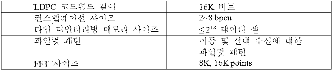


Claims (4)
- 방송 신호를 전송하는 방법에 있어서,In the method for transmitting a broadcast signal,인풋 포맷팅 블락이 인풋스트림을 복수개의 PLP(Physical Layer Pipe)로 포맷팅하는 단계;The input formatting block formatting the input stream into a plurality of physical layer pipes (PLPs);인코더가 상기 복수개의 PLP 내의 데이터들을 인코딩하는 단계;An encoder for encoding data in the plurality of PLPs;타임 인터리버가 상기 복수개의 PLP 내의 인코딩된 데이터를 타임 인터리빙하는 단계, 여기서 상기 타임 인터리빙하는 단계는, A time interleaver time interleaving encoded data in the plurality of PLPs, wherein the time interleaving comprises:셀 인터리버가 상기 복수개의 PLP 내의 한 FEC(Forward Error Correction) 블락의 셀들의 순서를 바꿈으로써 상기 인코딩된 데이터를 셀 인터리빙하는 단계를 포함하고;A cell interleaver for cell interleaving the encoded data by changing the order of cells of one Forward Error Correction (FEC) block in the plurality of PLPs;프레이머가 상기 타임 인터리빙된 데이터를 적어도 하나의 시그널 프레임으로 프레임 매핑하는 단계; 및Framer mapping the time interleaved data to at least one signal frame; And웨이브폼 블락이 상기 적어도 하나의 시그널 프레임의 매핑된 데이터를 웨이브폼 모듈레이팅하고, 상기 모듈레이팅된 데이터를 포함하는 방송 신호를 전송하는 단계; 를 포함하는 방송 신호 전송 방법.Waveform modulating the mapped data of the at least one signal frame and transmitting a broadcast signal including the modulated data; Broadcast signal transmission method comprising a.
- 제 1 항에 있어서, 상기 셀 인터리빙하는 단계는, The method of claim 1, wherein the cell interleaving comprises:상기 FEC 블락의 셀들을 선형적으로 메모리에 쓰는 단계, 및Linearly writing cells of the FEC block to memory, and치환 시퀀스를 이용하여 상기 메모리로부터 상기 셀들을 랜덤하게 읽는 단계를 더 포함하는 방송 신호 전송 방법.And randomly reading the cells from the memory using a substitution sequence.
- 인풋스트림을 복수개의 PLP(Physical Layer Pipe)로 포맷팅하는 인풋 포맷팅 블락;An input formatting block for formatting the input stream into a plurality of physical layer pipes (PLPs);상기 복수개의 PLP 내의 데이터를 인코딩하는 인코더;An encoder for encoding data in the plurality of PLPs;상기 복수개의 PLP 내의 인코딩된 데이터를 타임 인터리빙하는 타임 인터리버, 여기서 상기 타임 인터리버는A time interleaver for time interleaving encoded data in the plurality of PLPs, wherein the time interleaver상기 복수개의 PLP 내의 한 FEC(Forward Error Correction) 블락의 셀들의 순서를 변경함으로써 상기 인코딩된 데이터를 셀 인터리빙하는 셀 인터리버를 포함하고;A cell interleaver for cell interleaving the encoded data by changing the order of cells of one Forward Error Correction (FEC) block in the plurality of PLPs;상기 타임 인터리빙된 데이터를 적어도 하나의 시그널 프레임에 프레임 매핑하는 프레이머; 및A framer for frame mapping the time interleaved data to at least one signal frame; And상기 적어도 하나의 시그널 프레임내의 매핑된 데이터를 웨이브폼 모듈레이팅하고, 상기 모듈레이팅된 데이터를 포함하는 방송 신호를 전송하는 웨이브폼 모듈; 을 포함하는 방송 신호 전송 장치.A waveform module for modulating the mapped data in the at least one signal frame and transmitting a broadcast signal including the modulated data; Broadcast signal transmission apparatus comprising a.
- 제 3 항에 있어서, The method of claim 3, wherein상기 셀 인터리버는 상기 FEC 블락의 셀들을 선형적으로 메모리에 쓰고, 치환 시퀀스를 이용하여 상기 메모리로부터 상기 셀들을 랜덤하게 읽는 방송 신호 전송 장치.The cell interleaver linearly writes cells of the FEC block into a memory and randomly reads the cells from the memory using a substitution sequence.
Priority Applications (6)
| Application Number | Priority Date | Filing Date | Title |
|---|---|---|---|
| KR1020187035820A KR102004274B1 (en) | 2014-06-10 | 2015-04-21 | Broadcast signal transmitting apparatus, broadcast signal receiving apparatus, broadcast signal transmitting method, and broadcast signal receiving method |
| EP15806936.9A EP3157259A4 (en) | 2014-06-10 | 2015-04-21 | Broadcast signal transmitting apparatus, broadcast signal receiving apparatus, broadcast signal transmitting method, and broadcast signal receiving method |
| CA2950574A CA2950574C (en) | 2014-06-10 | 2015-04-21 | Broadcast signal transmitting apparatus, broadcast signal receiving apparatus, broadcast signal transmitting method, and broadcast signal receiving method |
| CN201580030810.4A CN106664436B (en) | 2014-06-10 | 2015-04-21 | Broadcast signal transmitting apparatus, broadcast signal receiving apparatus, broadcast signal transmitting method, and broadcast signal receiving method |
| KR1020167034375A KR101929782B1 (en) | 2014-06-10 | 2015-04-21 | Broadcast signal transmitting apparatus, broadcast signal receiving apparatus, broadcast signal transmitting method, and broadcast signal receiving method |
| MX2016016160A MX366500B (en) | 2014-06-10 | 2015-04-21 | Broadcast signal transmitting apparatus, broadcast signal receiving apparatus, broadcast signal transmitting method, and broadcast signal receiving method. |
Applications Claiming Priority (2)
| Application Number | Priority Date | Filing Date | Title |
|---|---|---|---|
| US201462010436P | 2014-06-10 | 2014-06-10 | |
| US62/010,436 | 2014-06-10 |
Publications (1)
| Publication Number | Publication Date |
|---|---|
| WO2015190694A1 true WO2015190694A1 (en) | 2015-12-17 |
Family
ID=54770411
Family Applications (2)
| Application Number | Title | Priority Date | Filing Date |
|---|---|---|---|
| PCT/KR2015/003980 WO2015190694A1 (en) | 2014-06-10 | 2015-04-21 | Broadcast signal transmitting apparatus, broadcast signal receiving apparatus, broadcast signal transmitting method, and broadcast signal receiving method |
| PCT/KR2015/003981 WO2015190695A1 (en) | 2014-06-10 | 2015-04-21 | Broadcast signal transmitting apparatus, broadcast signal receiving apparatus, broadcast signal transmitting method, and broadcast signal receiving method |
Family Applications After (1)
| Application Number | Title | Priority Date | Filing Date |
|---|---|---|---|
| PCT/KR2015/003981 WO2015190695A1 (en) | 2014-06-10 | 2015-04-21 | Broadcast signal transmitting apparatus, broadcast signal receiving apparatus, broadcast signal transmitting method, and broadcast signal receiving method |
Country Status (7)
| Country | Link |
|---|---|
| US (6) | US9935734B2 (en) |
| EP (2) | EP3157259A4 (en) |
| KR (3) | KR101929782B1 (en) |
| CN (2) | CN106471800B (en) |
| CA (2) | CA2951875C (en) |
| MX (1) | MX366500B (en) |
| WO (2) | WO2015190694A1 (en) |
Families Citing this family (12)
| Publication number | Priority date | Publication date | Assignee | Title |
|---|---|---|---|---|
| KR101929782B1 (en) | 2014-06-10 | 2018-12-17 | 엘지전자 주식회사 | Broadcast signal transmitting apparatus, broadcast signal receiving apparatus, broadcast signal transmitting method, and broadcast signal receiving method |
| JP6317522B2 (en) | 2014-08-21 | 2018-04-25 | エルジー エレクトロニクス インコーポレイティド | Broadcast signal transmitting apparatus, broadcast signal receiving apparatus, and method for transmitting and receiving broadcast signals |
| WO2016060354A1 (en) * | 2014-10-12 | 2016-04-21 | 엘지전자 주식회사 | Broadcast signal transmission apparatus, broadcast signal reception apparatus, broadcast signal transmission method, and broadcast signal reception method |
| KR101558172B1 (en) * | 2014-10-14 | 2015-10-08 | 숭실대학교산학협력단 | The method and device for interleaving for error distribution and the recording medium for performing the method |
| JP6480569B2 (en) * | 2015-07-27 | 2019-03-13 | エルジー エレクトロニクス インコーポレイティド | Broadcast signal transmitting / receiving apparatus and method |
| CA2965067C (en) | 2016-04-26 | 2020-08-25 | Electronics And Telecommunications Research Institute | Apparatus for time interleaving and method using the same |
| WO2017204369A1 (en) | 2016-05-24 | 2017-11-30 | 엘지전자(주) | Device and method for receiving broadcast signal |
| WO2017204370A1 (en) * | 2016-05-24 | 2017-11-30 | 엘지전자(주) | Device and method for receiving broadcast signal |
| WO2017204376A1 (en) * | 2016-05-24 | 2017-11-30 | 엘지전자 주식회사 | Broadcast signal transmission device, broadcast signal reception device, broadcast signal transmission method, and broadcast signal reception method |
| EP3343801A1 (en) * | 2016-12-30 | 2018-07-04 | Eutelsat S.A. | Method for protection of signal blockages in a satellite mobile broadcast system |
| KR101967299B1 (en) * | 2017-12-19 | 2019-04-09 | 엘지전자 주식회사 | Autonomous vehicle for receiving a broadcasting signal and method of Autonomous vehicle for receiving a broadcasting signal |
| CN108039937B (en) * | 2017-12-20 | 2021-01-08 | 北京数码视讯科技股份有限公司 | Resource optimization method and device in baseband processing and electronic equipment |
Citations (5)
| Publication number | Priority date | Publication date | Assignee | Title |
|---|---|---|---|---|
| WO2011105786A2 (en) * | 2010-02-23 | 2011-09-01 | 엘지전자 주식회사 | Broadcasting signal transmitter/receiver and broadcasting signal transmission/reception method |
| US20110305300A1 (en) * | 2009-01-09 | 2011-12-15 | Woo Suk Ko | Apparatus for transmitting and receiving a signal and method of transmitting and receiving a signal |
| US20130235952A1 (en) * | 2010-11-17 | 2013-09-12 | Lg Electronics Inc. | Broadcast-signal transmitter/receiver and method for transmitting/receiving broadcast signals |
| KR20130121881A (en) * | 2010-11-23 | 2013-11-06 | 엘지전자 주식회사 | Broadcast signal transmitter/receiver, and broadcast signal transceiving method |
| KR20140061326A (en) * | 2008-02-04 | 2014-05-21 | 엘지전자 주식회사 | Method of transmitting and receiving a signal and apparatus thereof |
Family Cites Families (20)
| Publication number | Priority date | Publication date | Assignee | Title |
|---|---|---|---|---|
| JP2000209213A (en) * | 1999-01-11 | 2000-07-28 | Matsushita Electric Ind Co Ltd | Interleave device and receiving device |
| CN1702976B (en) * | 2005-06-22 | 2011-06-08 | 中山大学 | Interleaving/deinterleaving method for communication system |
| US9419749B2 (en) * | 2009-08-19 | 2016-08-16 | Qualcomm Incorporated | Methods and apparatus employing FEC codes with permanent inactivation of symbols for encoding and decoding processes |
| KR101285108B1 (en) | 2007-03-08 | 2013-07-11 | 노키아 코포레이션 | Interoperability of digital broadband broadcasting and cellular communication systems |
| US8751769B2 (en) * | 2007-12-21 | 2014-06-10 | Qualcomm Incorporated | Efficient address generation for pruned interleavers and de-interleavers |
| KR100937430B1 (en) * | 2008-01-25 | 2010-01-18 | 엘지전자 주식회사 | Method of transmitting and receiving a signal and apparatus thereof |
| CN102217224B (en) * | 2008-11-12 | 2014-07-16 | Lg电子株式会社 | Apparatus for transmitting and receiving a signal and method of transmitting and receiving a signal |
| US8670494B2 (en) * | 2009-03-03 | 2014-03-11 | Lg Electronics Inc. | Apparatus for transmitting and receiving a signal and method of transmitting and receiving a signal |
| JP5440836B2 (en) * | 2009-03-24 | 2014-03-12 | ソニー株式会社 | Receiving apparatus and method, program, and receiving system |
| KR101108000B1 (en) * | 2009-09-02 | 2012-01-25 | 펄스텔레콤(주) | System for Time Division Multiplexing in Satellite Digital Multi media Broadcasting and the method therefor |
| TW201141198A (en) * | 2009-10-20 | 2011-11-16 | Sony Corp | Frame mapping apparatus and method |
| KR101267632B1 (en) * | 2009-12-18 | 2013-05-23 | 한국전자통신연구원 | Transmitter and receiver for terrestrial digital multimediabroadcasting |
| US8601340B2 (en) * | 2011-07-25 | 2013-12-03 | Cortina Systems, Inc. | Time varying data permutation apparatus and methods |
| US9106265B2 (en) | 2011-11-04 | 2015-08-11 | Silicon Laboratories Inc. | Receive data flow path using a single FEC decoder |
| ES2960089T3 (en) * | 2012-06-08 | 2024-02-29 | Samsung Electronics Co Ltd | Method and apparatus for concealing frame errors and method and apparatus for audio decoding |
| WO2014046526A1 (en) * | 2012-09-24 | 2014-03-27 | 삼성전자 주식회사 | Method and apparatus for concealing frame errors, and method and apparatus for decoding audios |
| US8929471B2 (en) * | 2012-10-26 | 2015-01-06 | Intel Corporation | Methods and systems to mitigate impulse interference |
| US9497056B2 (en) | 2014-06-09 | 2016-11-15 | Allen LeRoy Limberg | Conveying metadata by modulation of pilot carriers in COFDM broadcasting |
| KR101929782B1 (en) * | 2014-06-10 | 2018-12-17 | 엘지전자 주식회사 | Broadcast signal transmitting apparatus, broadcast signal receiving apparatus, broadcast signal transmitting method, and broadcast signal receiving method |
| JP6317522B2 (en) * | 2014-08-21 | 2018-04-25 | エルジー エレクトロニクス インコーポレイティド | Broadcast signal transmitting apparatus, broadcast signal receiving apparatus, and method for transmitting and receiving broadcast signals |
-
2015
- 2015-04-21 KR KR1020167034375A patent/KR101929782B1/en active IP Right Grant
- 2015-04-21 KR KR1020187035820A patent/KR102004274B1/en active IP Right Grant
- 2015-04-21 EP EP15806936.9A patent/EP3157259A4/en not_active Withdrawn
- 2015-04-21 WO PCT/KR2015/003980 patent/WO2015190694A1/en active Application Filing
- 2015-04-21 CN CN201580030831.6A patent/CN106471800B/en active Active
- 2015-04-21 KR KR1020167034374A patent/KR101899826B1/en active IP Right Grant
- 2015-04-21 CA CA2951875A patent/CA2951875C/en active Active
- 2015-04-21 WO PCT/KR2015/003981 patent/WO2015190695A1/en active Application Filing
- 2015-04-21 MX MX2016016160A patent/MX366500B/en active IP Right Grant
- 2015-04-21 EP EP15807342.9A patent/EP3157253A4/en not_active Ceased
- 2015-04-21 CA CA2950574A patent/CA2950574C/en active Active
- 2015-04-21 CN CN201580030810.4A patent/CN106664436B/en active Active
- 2015-05-14 US US14/712,021 patent/US9935734B2/en active Active
- 2015-05-14 US US14/711,987 patent/US9667380B2/en active Active
-
2016
- 2016-07-22 US US15/217,756 patent/US10057008B2/en active Active
-
2017
- 2017-04-25 US US15/496,299 patent/US9935657B2/en active Active
-
2018
- 2018-02-08 US US15/891,961 patent/US10277254B2/en active Active
- 2018-10-22 US US16/166,978 patent/US10263642B2/en active Active
Patent Citations (5)
| Publication number | Priority date | Publication date | Assignee | Title |
|---|---|---|---|---|
| KR20140061326A (en) * | 2008-02-04 | 2014-05-21 | 엘지전자 주식회사 | Method of transmitting and receiving a signal and apparatus thereof |
| US20110305300A1 (en) * | 2009-01-09 | 2011-12-15 | Woo Suk Ko | Apparatus for transmitting and receiving a signal and method of transmitting and receiving a signal |
| WO2011105786A2 (en) * | 2010-02-23 | 2011-09-01 | 엘지전자 주식회사 | Broadcasting signal transmitter/receiver and broadcasting signal transmission/reception method |
| US20130235952A1 (en) * | 2010-11-17 | 2013-09-12 | Lg Electronics Inc. | Broadcast-signal transmitter/receiver and method for transmitting/receiving broadcast signals |
| KR20130121881A (en) * | 2010-11-23 | 2013-11-06 | 엘지전자 주식회사 | Broadcast signal transmitter/receiver, and broadcast signal transceiving method |
Non-Patent Citations (1)
| Title |
|---|
| See also references of EP3157259A4 * |
Also Published As
Similar Documents
| Publication | Publication Date | Title |
|---|---|---|
| WO2016122060A1 (en) | Broadcast signal transmitting apparatus, broadcast signal receiving apparatus, broadcast signal transmitting method, and broadcast signal receiving method | |
| WO2015163597A1 (en) | Broadcasting signal transmission apparatus, broadcasting signal reception apparatus, broadcasting signal transmission method, and broadcasting reception method | |
| WO2016163620A1 (en) | Apparatus and method for transmitting and receiving broadcast signal | |
| WO2016093467A1 (en) | Broadcast signal transmitting device, broadcast signal receiving device, broadcast signal transmitting method, and broadcast signal receiving method | |
| WO2016125989A1 (en) | Apparatus and method for transreceiving broadcast signals | |
| WO2015156569A1 (en) | Broadcasting signal transmission device, broadcasting signal reception device, broadcasting signal transmission method, and broadcasting signal reception method | |
| WO2016108366A1 (en) | Broadcast signal transmission apparatus, broadcast signal reception apparatus, broadcast signal transmission method, and broadcast signal reception method | |
| WO2015076511A1 (en) | Apparatus for transmitting broadcast signals, apparatus for receiving broadcast signals, method for transmitting broadcast signals and method for receiving broadcast signals | |
| WO2016144004A1 (en) | Broadcast signal transmission device, broadcast signal reception device, broadcast signal transmission method, and broadcast signal reception method | |
| WO2015190694A1 (en) | Broadcast signal transmitting apparatus, broadcast signal receiving apparatus, broadcast signal transmitting method, and broadcast signal receiving method | |
| WO2016060354A1 (en) | Broadcast signal transmission apparatus, broadcast signal reception apparatus, broadcast signal transmission method, and broadcast signal reception method | |
| WO2016027965A1 (en) | Apparatus for transmitting broadcast signal, apparatus for receiving broadcast signal, method for transmitting broadcast signal, and method for receiving broadcast signal | |
| WO2015182900A1 (en) | Broadcast signal transmission device, broadcast signal reception device, broadcast signal transmission method and broadcast signal reception method | |
| WO2017014356A1 (en) | Broadcast signal transmission/reception device and method | |
| WO2017010655A1 (en) | Broadcast signal transmitting device, broadcast signal receiving device, broadcast signal transmitting method, and broadcast signal receiving method | |
| WO2016153127A1 (en) | Broadcast signal transmission or reception device and method | |
| WO2016108372A1 (en) | Broadcasting signal transmission device, broadcasting signal reception device, broadcasting signal transmission method, and broadcasting signal reception method | |
| WO2016122063A1 (en) | Apparatus and method for transreceiving broadcast signals | |
| WO2016153142A1 (en) | Broadcast signal transmission device, broadcast signal reception device, broadcast signal transmission method, and broadcast signal reception method | |
| WO2017003038A1 (en) | Device and method for transreceiving broadcast signals | |
| WO2016085083A1 (en) | Apparatus and method for transmitting and receiving broadcast signal | |
| WO2015186938A1 (en) | Apparatus for transmitting broadcast signals, apparatus for receiving broadcast signals, method for transmitting broadcast signals, and method for receiving broadcast signals | |
| WO2016125970A1 (en) | Broadcast signal transmission device, broadcast signal reception device, broadcast signal transmission method, and broadcast signal reception method | |
| WO2016153118A1 (en) | Device and method for transmitting and receiving broadcast signal | |
| WO2017043714A1 (en) | Broadcast signal transmission apparatus, broadcast signal reception apparatus, broadcast signal transmission method, and broadcast signal reception method |
Legal Events
| Date | Code | Title | Description |
|---|---|---|---|
| 121 | Ep: the epo has been informed by wipo that ep was designated in this application |
Ref document number: 15806936 Country of ref document: EP Kind code of ref document: A1 |
|
| ENP | Entry into the national phase |
Ref document number: 2950574 Country of ref document: CA |
|
| ENP | Entry into the national phase |
Ref document number: 20167034375 Country of ref document: KR Kind code of ref document: A |
|
| WWE | Wipo information: entry into national phase |
Ref document number: MX/A/2016/016160 Country of ref document: MX |
|
| NENP | Non-entry into the national phase |
Ref country code: DE |
|
| REEP | Request for entry into the european phase |
Ref document number: 2015806936 Country of ref document: EP |
|
| WWE | Wipo information: entry into national phase |
Ref document number: 2015806936 Country of ref document: EP |