WO2016125630A1 - 評価装置、評価方法、及び記録媒体 - Google Patents
評価装置、評価方法、及び記録媒体 Download PDFInfo
- Publication number
- WO2016125630A1 WO2016125630A1 PCT/JP2016/052147 JP2016052147W WO2016125630A1 WO 2016125630 A1 WO2016125630 A1 WO 2016125630A1 JP 2016052147 W JP2016052147 W JP 2016052147W WO 2016125630 A1 WO2016125630 A1 WO 2016125630A1
- Authority
- WO
- WIPO (PCT)
- Prior art keywords
- evaluation
- record
- flow
- data
- amount
- Prior art date
- Legal status (The legal status is an assumption and is not a legal conclusion. Google has not performed a legal analysis and makes no representation as to the accuracy of the status listed.)
- Ceased
Links
Images


Classifications
-
- H—ELECTRICITY
- H04—ELECTRIC COMMUNICATION TECHNIQUE
- H04L—TRANSMISSION OF DIGITAL INFORMATION, e.g. TELEGRAPHIC COMMUNICATION
- H04L47/00—Traffic control in data switching networks
- H04L47/10—Flow control; Congestion control
- H04L47/36—Flow control; Congestion control by determining packet size, e.g. maximum transfer unit [MTU]
-
- H—ELECTRICITY
- H04—ELECTRIC COMMUNICATION TECHNIQUE
- H04L—TRANSMISSION OF DIGITAL INFORMATION, e.g. TELEGRAPHIC COMMUNICATION
- H04L43/00—Arrangements for monitoring or testing data switching networks
- H04L43/20—Arrangements for monitoring or testing data switching networks the monitoring system or the monitored elements being virtualised, abstracted or software-defined entities, e.g. SDN or NFV
-
- H—ELECTRICITY
- H04—ELECTRIC COMMUNICATION TECHNIQUE
- H04L—TRANSMISSION OF DIGITAL INFORMATION, e.g. TELEGRAPHIC COMMUNICATION
- H04L43/00—Arrangements for monitoring or testing data switching networks
- H04L43/02—Capturing of monitoring data
- H04L43/026—Capturing of monitoring data using flow identification
-
- H—ELECTRICITY
- H04—ELECTRIC COMMUNICATION TECHNIQUE
- H04L—TRANSMISSION OF DIGITAL INFORMATION, e.g. TELEGRAPHIC COMMUNICATION
- H04L43/00—Arrangements for monitoring or testing data switching networks
- H04L43/08—Monitoring or testing based on specific metrics, e.g. QoS, energy consumption or environmental parameters
- H04L43/0876—Network utilisation, e.g. volume of load or congestion level
-
- H—ELECTRICITY
- H04—ELECTRIC COMMUNICATION TECHNIQUE
- H04L—TRANSMISSION OF DIGITAL INFORMATION, e.g. TELEGRAPHIC COMMUNICATION
- H04L49/00—Packet switching elements
- H04L49/25—Routing or path finding in a switch fabric
- H04L49/253—Routing or path finding in a switch fabric using establishment or release of connections between ports
-
- H—ELECTRICITY
- H04—ELECTRIC COMMUNICATION TECHNIQUE
- H04M—TELEPHONIC COMMUNICATION
- H04M11/00—Telephonic communication systems specially adapted for combination with other electrical systems
Definitions
- the present invention relates to an evaluation apparatus, an evaluation method, and a recording medium.
- SDN Software Defined Network
- OpenFlow OpenFlow
- the flow entry includes a flow identification field and an action field.
- the flow identification field indicates conditions for a flow (for example, a packet) such as an incoming / outgoing IP address, an outgoing / incoming port number, and a protocol number.
- the action field indicates a method of processing a flow (for example, a packet) that matches a condition such as output to a specific port or drop of a flow.
- a flow entry that includes a wild card in the condition multiple flows can be controlled by a single entry.
- a flow entry including a wild card By using a flow entry including a wild card, a large number of flows can be controlled with a small number of flow entries.
- spike flow a large amount of flow (spike flow) may occur suddenly on the Internet.
- spike flows are concentrated on a specific link, congestion occurs in the link, and as a result, the performance of the entire network may be degraded.
- the performance of the entire network can be prevented by performing individual control such as traffic shaping and detour control.
- the above individual control may be performed based on the spike flow arrival / departure address and port number, but these factors should be identified by diversifying applications and network terminals. Is becoming increasingly difficult.
- the present invention has been made in view of the above points, and an object of the present invention is to make it possible to evaluate the possibility of suddenly generating a large amount of flow.
- the evaluation apparatus for each record used for transfer control of data flowing through the network, based on the history of the data amount that matches the condition of the record, the magnitude of the variation in the data amount.
- a first evaluation unit that evaluates each of the records
- a second evaluation unit that evaluates the size of the space of the record, based on the condition of the record, and an evaluation result by the first evaluation unit, Based on the evaluation result by the second evaluation unit, for each record, an index value indicating the possibility that data related to a data amount equal to or greater than a predetermined amount within a certain period matches the condition of the record is calculated.
- a calculation unit for each record used for transfer control of data flowing through the network, based on the history of the data amount that matches the condition of the record, the magnitude of the variation in the data amount.
- FIG. 1 is a diagram illustrating a network configuration example according to an embodiment of the present invention.
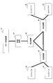
- four edge nodes 40, three transfer devices 30, one control device 20, and one flow evaluation device 10 are shown.
- Each edge node 40 is a device that generates packet traffic. That is, each edge node 40 corresponds to a packet source or destination. Each edge node 40 is connected to one of the transfer devices 30 via a network.
- Each transfer device 30 is a switch (OpenFlow switch) corresponding to SDN (Software Defined Network) / OpenFlow.
- Each transfer device 30 is connected to one of the edge nodes 40 or another transfer device 30 via a network.
- Each transfer device 30 controls the flow of packets between the edge nodes 40 according to a flow table that is a set of flow entries.
- the flow entry is information used for transfer control of data flowing through the network, and includes a flow identifier, an action, a flow counter, and the like.
- the flow identifier indicates a condition for a flow (for example, a packet).
- the action indicates a method of processing a flow (for example, data such as a packet) that matches the condition of the flow entry.
- the flow counter is statistical information and indicates, for example, the number of packets and the number of bytes transferred in accordance with the conditions of the flow entry. In the present embodiment, the number of packets or bytes is referred to as “traffic amount”.
- the control device 20 is a controller (OpenFlow controller) corresponding to SDN / OpenFlow.
- the control device 20 sets a flow table for each transfer device 30.
- the control device 20 also periodically accesses each transfer device 30 and acquires the flow identifier and flow counter value of each flow entry in each transfer device 30.
- the connection form between the control device 20 and each transfer device 30 is not limited to a predetermined one.
- the flow evaluation device 10 acquires the flow identifier and flow counter value of each flow entry in the flow table of each transfer device 30 from the control device 20, and calculates a spike index based on the acquired flow identifier and flow counter value. It is a computer.
- the spike index is an index value indicating a possibility that a large amount of flows (hereinafter referred to as “spike flows”) may be suddenly matched (matches the condition of the flow entry).
- the spike index is an index value indicating a possibility that a predetermined amount of flows or more match within a certain period. Since the spike index of each flow entry is evaluated in advance, individual control can be performed on the flow entry having a high spike index, and performance degradation of the entire network can be prevented.
- the flow evaluation apparatus 10 is connected to the control apparatus 20 via a network.
- FIG. 2 is a diagram illustrating a hardware configuration example of the flow evaluation apparatus according to the embodiment of the present invention. 2 includes a drive device 100, an auxiliary storage device 102, a memory device 103, a CPU 104, an interface device 105, and the like that are mutually connected by a bus B.
- a program for realizing the processing in the flow evaluation apparatus 10 is provided by a recording medium 101 such as a CD-ROM.
- a recording medium 101 such as a CD-ROM.
- the program is installed from the recording medium 101 to the auxiliary storage device 102 via the drive device 100.
- the program need not be installed from the recording medium 101 and may be downloaded from another computer via a network.
- the auxiliary storage device 102 stores the installed program and also stores necessary files and data.
- the memory device 103 reads the program from the auxiliary storage device 102 and stores it when there is an instruction to start the program.
- the CPU 104 executes functions related to the flow evaluation device 10 in accordance with a program stored in the memory device 103.
- the interface device 105 is used as an interface for connecting to a network.
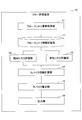
- FIG. 3 is a diagram illustrating a functional configuration example of the flow evaluation apparatus according to the embodiment of the present invention.
- the flow evaluation apparatus 10 includes a flow entry information acquisition unit 11, a known risk evaluation unit 12, an unknown risk evaluation unit 13, a spike index calculation unit 14, a spike estimation unit 15, an output unit 16, and the like. Each of these units is realized by processing that one or more programs installed in the flow evaluation apparatus 10 cause the CPU 104 to execute.
- the flow evaluation apparatus 10 also uses the flow entry information storage unit 17.
- the flow entry information storage unit 17 can be realized by using the auxiliary storage device 102 or a storage device that can be connected to the flow evaluation device 10 via a network.
- the flow entry information acquisition unit 11 acquires the flow identifier and the flow counter value of each flow entry of each transfer device 30 from the control device 20.
- the acquired flow identifier and flow counter value are stored in the flow entry information storage unit 17 for each flow entry.
- the known risk evaluation unit 12 evaluates the amount of fluctuation of the data amount (traffic amount) for each flow entry based on the history of the data amount (traffic amount) that matches the condition of the flow entry. More specifically, the known risk evaluation unit 12 generates again a spike flow that has been observed in the past based on a past traffic fluctuation pattern indicated by a past time-series traffic amount (flow counter value) of each flow entry. Risk (hereinafter referred to as “known risk”) for each flow entry. The evaluation result is indexed to a predetermined evaluation value.
- the unknown risk evaluation unit 13 evaluates the size of the space of the flow entry based on the condition of the flow entry for each flow entry. More specifically, a risk that an unknown spike flow will occur in the future (hereinafter referred to as “unknown risk”) is evaluated based on the flow space indicated by the flow identifier of each flow entry. The evaluation result is indexed to a predetermined evaluation value. Details of the flow space will be described later.
- the spike index calculation unit 14 calculates a spike index for each flow entry based on the evaluation result by the known risk evaluation unit 12 and the evaluation result by the unknown risk evaluation unit 13. That is, the spike index calculation unit 14 divides the spike flow in the future into two types: (1) a known spike flow that has occurred in the past and (2) an unknown spike flow that has never occurred once.
- the spike index is calculated by classifying the patterns into risks and combining the risks (1) and (2).
- the spike estimation unit 15 estimates a flow entry that is likely to match a spike flow in the future based on the spike index calculated for each flow entry by the spike index calculation unit 14.
- the output unit 16 outputs the estimation result by the spike estimation unit 15.
- the output form is not limited to a predetermined one. For example, it may be displayed on a display device such as a liquid crystal display, or may be output to a printer. Alternatively, it may be transmitted via a network by e-mail or the like, for example.
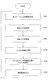
- FIG. 4 is a flowchart for explaining an example of a processing procedure executed by the flow evaluation apparatus.
- the flow entry information acquisition unit 11 includes information (hereinafter referred to as “flow identifier”, flow counter value, and the like of each flow entry in the flow table of each transfer device 30 collected from each transfer device 30 by the control device 20). , “Flow entry information”).
- the acquired flow entry information is stored in the flow entry information storage unit 17.
- FIG. 5 is a diagram illustrating a configuration example of the flow entry information storage unit.
- FIG. 5 shows one of the flow entry information tables stored for each flow entry in the flow entry information storage unit 17. That is, the flow entry information storage unit 17 stores a flow entry information table for each flow entry of each transfer device 30.
- Each record of the flow entry information table has items such as time, source IP address, destination IP address, source port number, destination port number, protocol number, and flow counter value.
- the time indicates a time when the flow entry information related to the record is acquired from the transfer device 30 by the control device 20. Therefore, a record is stored in the flow entry information table every time the flow entry information is collected from each transfer device 30 by the control device 20.
- the items from the source IP address to the protocol number are items constituting the flow identifier.
- the flow counter value is a flow counter value at the time of the record.
- step S101 is executed at the same cycle as the cycle of collecting flow entry information by the control device 20. Therefore, in step S101, one record is added to each flow entry information table corresponding to each flow entry of each transfer device 30.
- the known risk evaluation unit 12 refers to the flow entry information storage unit 17 to evaluate the known risk (S102).
- the known risk evaluation unit 12 evaluates the known risk based on the number (ratio) of occurrences of spike flow in the past traffic amount variation or the variation coefficient of the past traffic amount variation.
- the former is evaluated by the 5 ⁇ -method.
- the latter is evaluated by a CV (Coefficient of variation) method.
- the standard deviation of traffic volume is used as a threshold value. Specifically, the standard deviation ⁇ of the traffic volume in a certain period in the past is calculated, and for each time included in the certain period, the standard deviation ⁇ is compared based on the comparison between the standard deviation ⁇ and the traffic volume at the time. The amount of change in the traffic volume during the period is evaluated. For example, the number of times when the traffic amount is 5 ⁇ value or more among the times included in the certain period is used as the known risk evaluation value. Note that 5 ⁇ as the threshold value is merely an example. It may be 3 ⁇ or another value based on ⁇ .
- the standard deviation ⁇ can be calculated by the following equation (1).
- y i (t n ) is the traffic volume at time t n of the flow entry i.
- the traffic volume at time t n a value obtained by subtracting the flow counter value at time t n-1 from the flow counter value at time t n.
- n indicates the time-series order of each time.
- the value of N is, for example, the number of times included in the evaluation period (the number of records in the flow entry information table).
- the evaluation period may be set in advance, for example. In the present embodiment, it is assumed that the value of N is 20.
- the known risk evaluation unit 12 calculates the standard deviation ⁇ for the latest 20 records (for the last 20 records) for each flow entry information table (that is, for each flow entry).
- the known risk evaluation unit 12 counts the number of records having a flow counter value of 5 ⁇ or more (that is, the number of times) among the 20 records.
- the count result of the number of records is the evaluation value of the known risk by the 5 ⁇ -method in the latest evaluation period.
- the length of the evaluation period is the same every time. Therefore, the number of times when the flow counter value is 5 ⁇ or more in each evaluation period substantially indicates the proportion of times when the flow counter value is 5 ⁇ or more in each evaluation period. If the evaluation period is not constant, the value obtained by dividing the number of times that the flow counter value is 5 ⁇ or more in each evaluation period by the number of times in the evaluation period is a known risk by the 5 ⁇ -method. May be an evaluation value.
- a variation coefficient CV of a traffic variation pattern is used as an evaluation value.
- the variation coefficient CV is calculated by the following equation (2), for example.
- the coefficient of variation CV is a value obtained by dividing the standard deviation ⁇ by an average value (calculated average).
- the known risk evaluation unit 12 calculates the coefficient of variation CV for the 20 most recent records for each flow entry information table (that is, for each flow entry).
- step S102 either the 5 ⁇ -method or the CV method may be used.
- the standard deviation ⁇ may be an evaluation value of the known risk.
- Other evaluation values may be used as long as the values can evaluate the traffic fluctuation pattern.
- the unknown risk evaluation unit 13 evaluates the unknown risk for each flow entry based on the size of the flow space of the flow identifier of each flow entry (S103). Specifically, the size of the flow space is used as an evaluation value for the unknown risk. As a method for evaluating the size of the flow space, for example, a dimension method or a bit method is used.
- the number of unspecified dimensions in the flow identifier is used as an evaluation value of the size of the flow space (that is, an evaluation value of unknown risk).
- An unspecified dimension refers to a dimension (item) for which no value is specified in the flow identifier. For example, when the flow identifier is composed of five dimensions of a source IP address, a destination IP address, a source port number, a destination port number, and a protocol number, values are specified only for the destination IP address and the protocol number.
- the number of unspecified dimensions of the existing flow identifier is 3. Therefore, in this case, the evaluation value of the unknown risk is 3.
- the unknown risk evaluation unit 13 performs, for each flow entry information table (that is, for each flow entry), for example, the latest record (that is, the record in which the flow entry information acquired in step S101 is recorded).
- the latest record that is, the record in which the flow entry information acquired in step S101 is recorded.
- the source IP address, destination IP address, source port number, destination port number, and protocol number the number of items (dimensions) for which no value is specified is counted. This count result is the number of unspecified dimensions, and is an evaluation value of the unknown risk by the dimension method.
- the unspecified number of bits of the flow identifier is used as an evaluation value of the size of the flow space (that is, an evaluation value of unknown risk).
- An unspecified bit means the number of bits to which a wild card or a network mask is applied in the flow identifier. That is, the unspecified bit is the number of bits of the part whose value is not specified in the flow identifier.
- the flow identifier has a total of 104 bits: source IP address (32 bits) + destination IP address (32 bits) + source port number (16 bits) + destination port number (16 bits) + protocol number (8 bits)
- source IP address 32 bits
- destination IP address 32 bits
- source port number 16 bits
- destination port number 16 bits
- protocol number 8 bits
- the destination IP address and destination port number are specified with values (values that do not include wildcards), and values are not specified for other items, or wildcards are specified.
- the number of unspecified bits is 56 bits.
- a wild card may be specified as a part of the value of each item. In this case, the partial bit number is added to the unspecified bit number.
- the unknown risk evaluation unit 13 performs, for example, for each flow entry information table (that is, for each flow entry), the source IP address, destination IP address, source port number, destination port number of the latest record, In the protocol number, the number of bits of a part replaced with a wild card or a part for which a value is not specified is counted. This count result is the number of unspecified bits, and is an evaluation value of unknown risk by the Bit method.
- the ratio of the number of unspecified dimensions may be the evaluation value of the unknown risk.
- the ratio of the number of unspecified bits may be the evaluation value of the unknown risk.
- the number of dimensions and the total number of bits of the flow identifier are basically fixed. Therefore, the number of unspecified dimensions and the number of unspecified bits are substantially equal to the ratio of the number of unspecified dimensions or unspecified. It corresponds to the ratio of the number of bits.
- the spike index calculation unit 14 calculates the spike index SI of each flow entry based on the following equation (3) (S104).
- SI i Spike exponent of flow entry i
- Y i (y i (t 1 ), y i (t 2 ),..., Y i (t N )) T : Traffic amount of flow entry i (flow counter value) )
- y i (t) traffic volume at time t of flow entry i (flow counter value)
- f i Flow space of flow identifier of flow entry i
- ⁇ Weight coefficient for known risk
- ⁇ Weight coefficient for unknown risk
- U (f i ) Evaluation value of unknown risk
- the spike index calculation unit 14 substitutes the evaluation value of the known risk obtained in step S102 for the flow entry into E (Y i ) of Expression (3), and obtains the flow entry in step S103.
- the obtained unknown risk evaluation value is substituted into U (f i ) of Equation (3) to calculate the spike index of the flow entry.
- the weighting factors ⁇ and ⁇ may be selected according to the known risk and unknown risk evaluation methods. For example, for known risks, the ⁇ value for the 5 ⁇ -method and the ⁇ value for the CV method are preset, and the ⁇ value is selected depending on which evaluation method is used. Good. Similarly, for unknown risks, the ⁇ value for the Dimension method and the ⁇ value for the Bit method are preset, and the ⁇ value is selected depending on which evaluation method is used. Good. By doing so, the fluctuation of the spike index due to the difference in the evaluation method of the known risk and the fluctuation of the spike index due to the difference of the evaluation method of the unknown risk can be reduced, and the threshold for the spike index can be made constant. .
- the spike estimation unit 15 evaluates the spike index calculated for each flow entry of each transfer device 30 in step S104, and is likely to match the spike flow in each flow entry in the future.
- a flow entry (which is likely to cause a spike flow) is estimated (S105).
- a flow index that is likely to match a spike flow in the future may be estimated by comparing the spike index of each flow entry with a threshold value. That is, it may be estimated that a flow entry whose spike index is equal to or greater than a threshold is a flow entry that is highly likely to match a spike flow in the future.
- the threshold value may be set for each combination of the known risk evaluation method and the unknown risk evaluation method.
- 2 ⁇ 2 4 threshold values may be set.
- the threshold may be one.
- the output unit 16 outputs the estimation result by the spike estimation unit 15 in step S105 (S106). For example, identification information of a flow entry whose possibility of matching with a spike flow is greater than or equal to a threshold value may be output. Alternatively, the output unit 16 may output the spike index of each flow entry calculated in step S104.
- the flow evaluation device 10 may prototype the flow table of each transfer device 30 based on the spike index of each flow entry.
- flow data (traffic information) may be collected from each transfer device 30 and stored in the flow evaluation device 10.
- Flow data may be collected using techniques such as NetFlow.
- the flow data includes flow header information (5-tuple), time, and the number of bytes. This flow data is collected at each time and past flow data is stored in a database.
- the flow evaluation device 10 calculates a spike index for each flow entry constituting the newly prototyped flow table using the past flow data database information and the flow space information of the flow entry, and produces a prototyped flow. The risk of spike flow occurring with respect to the table may be evaluated. While repeating the trial production of the flow table (by trial and error), the flow table may be generated so that the spike flow does not concentrate on the specific flow entry, or the spike flow is gathered on the specific flow entry. The flow table may be generated so as to facilitate individual control.
- the spike index is calculated in real time.
- the spike index may be calculated batchwise.
- a record at a certain time is set as a processing target, and steps S101 and after are executed. Thereafter, step S101 and subsequent steps may be repeated while the processing target is shifted to the record at the next time.
- the evaluation value of the known risk is calculated based on the 20 most recent records regarding the record to be processed at that time.
- the spike index is calculated based on the known risk and the unknown risk. Therefore, not only the known spike flow but also the risk of an unknown spike flow can be taken into consideration, and the possibility of suddenly generating a large amount of flow can be evaluated.
- the spike index is calculated for each flow entry.
- the network administrator can perform traffic shaping and detour control in advance for traffic that matches a flow entry with a high spike index, so that the impact of network congestion when a spike flow occurs Can be reduced.
- the known risk evaluation unit 12 is an example of a first evaluation unit.
- the unknown risk evaluation unit 13 is an example of a second evaluation unit.
- the spike index calculation unit 14 is an example of a calculation unit.
- a flow entry is an example of a record used for transfer control of data distributed through a network. That is, the present embodiment may be applied to a record for controlling data transfer, which is used in a transfer apparatus compatible with a protocol other than OpenFlow.
Landscapes
- Engineering & Computer Science (AREA)
- Signal Processing (AREA)
- Computer Networks & Wireless Communication (AREA)
- Environmental & Geological Engineering (AREA)
- Data Exchanges In Wide-Area Networks (AREA)
- Telephonic Communication Services (AREA)
Abstract
評価装置は、ネットワークを流通するデータの転送制御に用いられるレコードごとに、当該レコードの条件に合致したデータ量の履歴に基づいて、前記データ量の変動の大きさを評価する第1の評価部と、前記レコードごとに、当該レコードの条件に基づいて、当該レコードの空間の大きさを評価する第2の評価部と、前記第1の評価部による評価結果と、前記第2の評価部による評価結果とに基づいて、前記レコードごとに、一定期間内に所定量以上のデータ量に係るデータが当該レコードの条件に合致する可能性を示す指標値を計算する計算部と、を有することで、突発的に大量のフローが発生する可能性を評価可能とする。
Description
本発明は、評価装置、評価方法、及び記録媒体に関する。
新しいトラヒック制御技術として、近年、OpenFlowに代表されるSDN(Software Defined Network)技術への注目が高まっている。SDN技術の登場により、従来のネットワーキング技術では困難であったマイクロフロー単位の経路制御が技術的に可能となった。また、NetFlow等のフロー計測技術の普及も進んでおり、マイクロフロー単位の詳細なトラヒック情報(フローデータ)を把握することが容易となっている。
OpenFlowでは、OpenFlowスイッチ上のフローエントリを用いてフローの制御が行われる。フローエントリはフロー識別フィールドとアクションフィールドとを含む。フロー識別フィールドは、発着IPアドレス、発着ポート番号、プロトコル番号等、フロー(例えば、パケット)に対する条件を示す。アクションフィールドは、特定ポートへの出力や、フローのドロップ等、条件に合致したフロー(例えば、パケット)の処理方法を示す。
条件にワイルドカードを含むフローエントリでは、単一のエントリで複数のフローを制御することができる。ワイルドカードを含むフローエントリを用いることで、少数のフローエントリで大量のフローを制御できる。
一方で、インターネットでは突発的に大量のフロー(スパイクフロー)が発生することがある。スパイクフローが特定のリンクに集中した場合、当該リンクにおいて輻輳が生じ、結果としてネットワーク全体のパフォーマンスが低下する可能性がある。
スパイクフローに対しては、トラヒックシェーピング、迂回制御といった個別制御を実施することで、ネットワーク全体のパフォーマンスの低下を防ぐことができる。
A. Lakhina, M. Crovella, and C. Diot. Diagnosing Network-Wide Traffic Anomalies. In ACM SIGCOMM,Portland, August 2004.
スパイクフローの要因が特定出来る場合には、スパイクフローの発着アドレス、発着ポート番号に基づいて、上記個別制御を実施すればよいが、アプリケーションやネットワーク端末の多様化によって、これらの要因を特定することがますます困難となっている。
本発明は、上記の点に鑑みてなされたものであって、突発的に大量のフローが発生する可能性を評価可能とすることを目的とする。
そこで上記課題を解決するため、評価装置は、ネットワークを流通するデータの転送制御に用いられるレコードごとに、当該レコードの条件に合致したデータ量の履歴に基づいて、前記データ量の変動の大きさを評価する第1の評価部と、前記レコードごとに、当該レコードの条件に基づいて、当該レコードの空間の大きさを評価する第2の評価部と、前記第1の評価部による評価結果と、前記第2の評価部による評価結果とに基づいて、前記レコードごとに、一定期間内に所定量以上のデータ量に係るデータが当該レコードの条件に合致する可能性を示す指標値を計算する計算部と、を有する。
突発的に大量のフローが発生する可能性を評価可能とすることができる。
以下、図面に基づいて本発明の実施の形態を説明する。図1は、本発明の実施の形態におけるネットワーク構成例を示す図である。図1には、4つのエッジノード40、3つの転送装置30、1つの制御装置20、及び1つのフロー評価装置10が示されている。
各エッジノード40は、パケットのトラヒックを発生させる装置である。すなわち、各エッジノード40は、パケットの発信元又は宛先に相当する。各エッジノード40は、いずれかの転送装置30にネットワークを介して接続される。
各転送装置30は、SDN(Software Defined Network)/OpenFlowに対応したスイッチ(OpenFlowスイッチ)である。各転送装置30は、いずれかのエッジノード40又は他の転送装置30にネットワークを介して接続される。各転送装置30は、フローエントリの集合であるフローテーブルに従って、エッジノード40間のパケットのフローを制御する。フローエントリは、ネットワークを流通するデータの転送制御に用いられる情報であり、フロー識別子、アクション、及びフローカウンタ等を含む。フロー識別子は、フロー(例えば、パケット)に対する条件を示す。アクションは、当該フローエントリの条件に合致したフロー(例えば、パケット等のデータ)の処理方法を示す。フローカウンタは、統計情報であり、例えば、当該フローエントリの条件に合致して転送されたパケット数およびバイト数を示す。なお、本実施の形態において、斯かるパケット数又はバイト数を、「トラヒック量」という。
制御装置20は、SDN/OpenFlowに対応したコントローラ(OpenFlowコントローラ)である。制御装置20は、各転送装置30に対してフローテーブルを設定する。制御装置20は、また、定期的に各転送装置30にアクセスし、各転送装置30における各フローエントリのフロー識別子及びフローカウンタ値を取得する。なお、制御装置20と各転送装置30との接続形態は、所定のものに限定されない。
フロー評価装置10は、各転送装置30のフローテーブルの各フローエントリのフロー識別子とフローカウンタ値とを制御装置20から取得し、取得されたフロー識別子及びフローカウンタ値に基づいてスパイク指数を計算するコンピュータである。スパイク指数とは、突発的に大量のフロー(以下、「スパイクフロー」という。)がマッチする(フローエントリの条件に合致する)可能性を示す指標値である。換言すれば、スパイク指数は、一定期間内に所定量以上のフローがマッチする可能性を示す指標値である。事前に各フローエントリのスパイク指数が評価されることで、スパイク指数の高いフローエントリに対して個別制御を実施し、ネットワーク全体のパフォーマンス低下を防ぐことができる。フロー評価装置10は、ネットワークを介して制御装置20に接続される。
図2は、本発明の実施の形態におけるフロー評価装置のハードウェア構成例を示す図である。図2のフロー評価装置10は、それぞれバスBで相互に接続されているドライブ装置100、補助記憶装置102、メモリ装置103、CPU104、及びインタフェース装置105等を有する。
フロー評価装置10での処理を実現するプログラムは、CD-ROM等の記録媒体101によって提供される。プログラムを記憶した記録媒体101がドライブ装置100にセットされると、プログラムが記録媒体101からドライブ装置100を介して補助記憶装置102にインストールされる。但し、プログラムのインストールは必ずしも記録媒体101より行う必要はなく、ネットワークを介して他のコンピュータよりダウンロードするようにしてもよい。補助記憶装置102は、インストールされたプログラムを格納すると共に、必要なファイルやデータ等を格納する。
メモリ装置103は、プログラムの起動指示があった場合に、補助記憶装置102からプログラムを読み出して格納する。CPU104は、メモリ装置103に格納されたプログラムに従ってフロー評価装置10に係る機能を実行する。インタフェース装置105は、ネットワークに接続するためのインタフェースとして用いられる。
図3は、本発明の実施の形態におけるフロー評価装置の機能構成例を示す図である。図3において、フロー評価装置10は、フローエントリ情報取得部11、既知リスク評価部12、未知リスク評価部13、スパイク指数計算部14、スパイク推定部15、及び出力部16等を有する。これら各部は、フロー評価装置10にインストールされた1以上のプログラムが、CPU104に実行させる処理により実現される。フロー評価装置10は、また、フローエントリ情報記憶部17を利用する。フローエントリ情報記憶部17は、補助記憶装置102、又はフロー評価装置10にネットワークを介して接続可能な記憶装置等を用いて実現可能である。
フローエントリ情報取得部11は、各転送装置30の各フローエントリのフロー識別子及びフローカウンタ値を、制御装置20から取得する。取得されたフロー識別子及びフローカウンタ値は、フローエントリごとに、フローエントリ情報記憶部17に記憶される。
既知リスク評価部12は、フローエントリごとに、当該フローエントリの条件に合致したデータ量(トラヒック量)の履歴に基づいて、データ量(トラヒック量)の変動の大きさを評価する。より詳しくは、既知リスク評価部12は、各フローエントリの過去の時系列のトラヒック量(フローカウンタ値)が示す、過去のトラヒックの変動パターンに基づいて、過去に観測済みのスパイクフローが再度発生するリスク(以下、「既知リスク」という。)を、フローエントリごとに評価する。評価結果は、所定の評価値に指標化される。
未知リスク評価部13は、フローエントリごとに、当該フローエントリの条件に基づいて、当該フローエントリの空間の大きさを評価する。より詳しくは、各フローエントリのフロー識別子が示すフロー空間に基づいて、将来に未知のスパイクフローが発生するリスク(以下、「未知リスク」という。)を評価する。評価結果は、所定の評価値に指標化される。なお、フロー空間の詳細については後述される。
スパイク指数計算部14は、既知リスク評価部12による評価結果と、未知リスク評価部13による評価結果とに基づいて、フローエントリごとに、スパイク指数を計算する。すなわち、スパイク指数計算部14は、将来におけるスパイクフローを、(1)過去に発生したことのある既知のスパイクフローと、(2)1度も発生したことのない未知のスパイクフローとの2つのパターンに分類し、(1)及び(2)のそれぞれのリスクを併せてスパイク指数を計算する。
スパイク推定部15は、スパイク指数計算部14によってフローエントリごとに計算されたスパイク指数に基づいて、将来的にスパイクフローにマッチする可能性の高いフローエントリを推定する。
出力部16は、スパイク推定部15による推定結果を出力する。出力形態は所定のものに限定されない。例えば、液晶ディスプレイ等の表示装置への表示であってもよいし、プリンタへの出力であってもよい。又は、例えば、電子メール等によって、ネットワークを介して送信されてもよい。
以下、フロー評価装置10が実行する処理手順について説明する。図4は、フロー評価装置が実行する処理手順の一例を説明するためのフローチャートである。
ステップS101において、フローエントリ情報取得部11は、制御装置20によって各転送装置30から収集されている、各転送装置30のフローテーブルの各フローエントリのフロー識別子及びフローカウンタ値等を含む情報(以下、「フローエントリ情報」という。)を取得する。取得されたフローエントリ情報は、フローエントリ情報記憶部17に記憶される。
図5は、フローエントリ情報記憶部の構成例を示す図である。図5には、フローエントリ情報記憶部17において、フローエントリごとに記憶されているフローエントリ情報テーブルのうちの一つが示されている。すなわち、フローエントリ情報記憶部17には、各転送装置30のフローエントリごとに、フローエントリ情報テーブルが記憶されている。
フローエントリ情報テーブルの各レコードは、時刻、発信元IPアドレス、宛先IPアドレス、発信元ポート番号、宛先ポート番号、プロトコル番号、及びフローカウンタ値等の項目を有する。時刻は、制御装置20によって、当該レコードに係るフローエントリ情報が転送装置30から取得された時刻を示す。したがって、フローエントリ情報テーブルには、制御装置20による、各転送装置30からのフローエントリ情報の収集時期ごとに、レコードが記憶される。
発信元IPアドレスからプロトコル番号までは、フロー識別子を構成する項目である。フローカウンタ値は、当該レコードの時刻における、フローカウンタ値である。
なお、ここでは、ステップS101が、制御装置20によるフローエントリ情報の収集の周期と同じ周期で実行されることとする。したがって、ステップS101では、各転送装置30の各フローエントリに対応する各フローエントリ情報テーブルに、1つのレコードが追加される。
続いて、既知リスク評価部12は、フローエントリ情報記憶部17を参照して既知リスクを評価する(S102)。既知リスク評価部12は、既知リスクを、過去のトラヒック量の変動の中でスパイクフローが発生した回数(割合)、又は過去のトラヒック量の変動の変動係数に基づいて評価する。前者は、5σ-法で評価される。後者は、CV(Coefficient of variation)法で評価される。
5σ-法では、トラヒック量の標準偏差が閾値として用いられる。具体的には、過去の或る期間のトラヒック量の標準偏差σを計算し、当該或る期間に含まれる各時刻について、標準偏差σと当該時刻におけるトラヒック量との比較に基づいて、当該或る期間におけるトラヒック量の変動の大きさが評価される。例えば、当該或る期間に含まれる時刻のうち、トラヒック量が5σ値以上である時刻の回数が、既知リスクの評価値として用いられる。なお、閾値としての5σは一例に過ぎない。3σであってもよいし、σに基づく他の値であってもよい。
なお、標準偏差σは、以下の式(1)によって算出可能である。

5σ-法において、既知リスク評価部12は、各フローエントリ情報テーブルについて(すなわち、各フローエントリについて)、直近の20個分(最後から20個分)のレコードについて、標準偏差σを算出する。既知リスク評価部12は、当該20個のレコードの中で、フローカウンタ値が5σ以上であるレコードの数(すなわち、時刻の数)をカウントする。当該レコードの数のカウント結果が、直近の評価期間における、5σ-法による既知リスクの評価値である。なお、ステップS101以降が、一定期間ごとに繰り返される過程において、評価期間の長さは、毎回同じである。したがって、各評価期間において、フローカウンタ値が5σ以上である時刻の数は、実質的に、各評価期間において、フローカウンタ値が5σ以上である時刻の割合を示す。なお、仮に、評価期間が一定でない場合には、各評価期間において、フローカウンタ値が5σ以上である時刻の数を、当該評価期間における時刻の数によって除した値が、5σ-法による既知リスクの評価値とされてもよい。
一方、CV法は、トラヒック変動パターンの変動係数CVが、評価値として用いられる。変動係数CVは、例えば、以下の式(2)よって算出される。
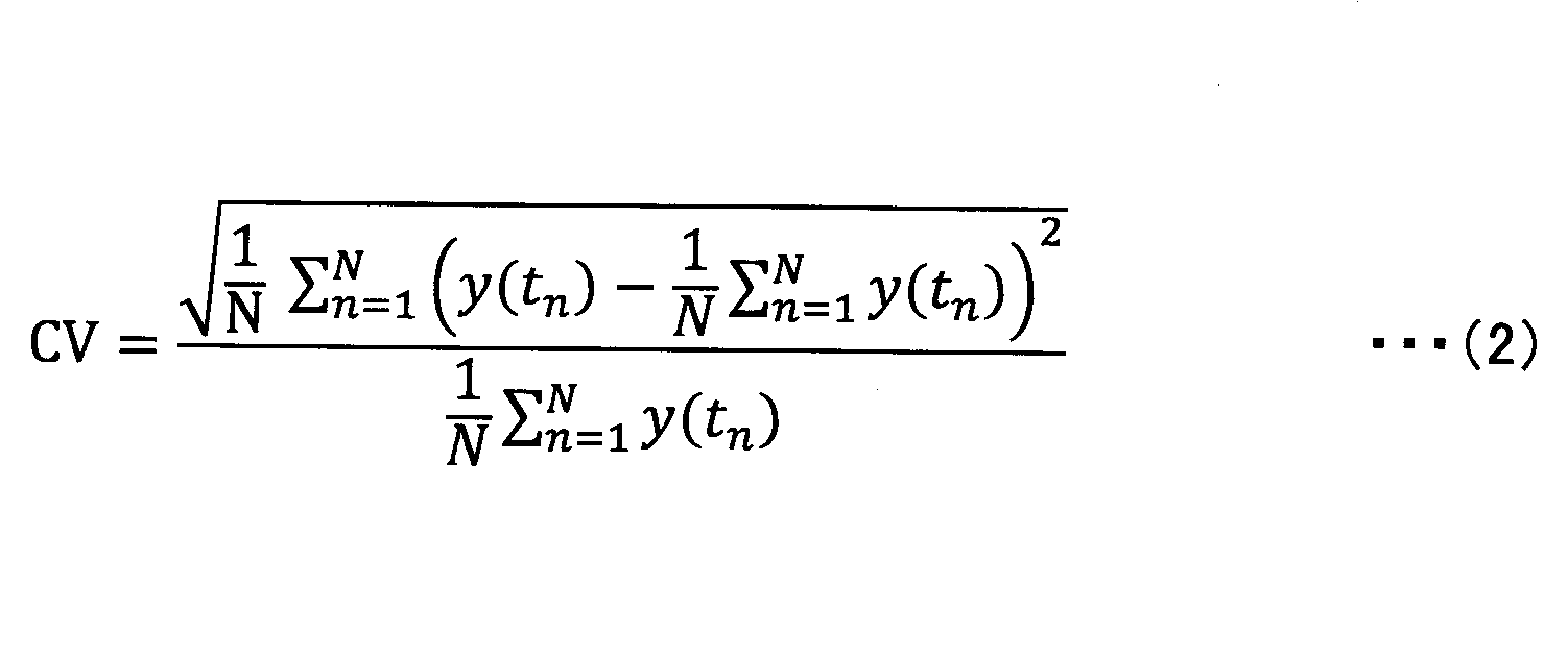
CV法において、既知リスク評価部12は、各フローエントリ情報テーブルについて(すなわち、各フローエントリについて)、直近の20個分のレコードについて、変動係数CVを計算する。
なお、ステップS102では、5σ-法及びCV法のいずれが使用されてもよい。また、例えば、標準偏差σが、既知リスクの評価値とされてもよい。トラヒックの変動パターンを評価することが可能な値であれば、その他の評価値が用いられてもよい。
続いて、未知リスク評価部13は、各フローエントリのフロー識別子のフロー空間の大きさに基づいて、未知リスクをフローエントリごとに評価する(S103)。具体的には、フロー空間の大きさが、未知リスクの評価値とされる。フロー空間の大きさの評価方法としては、例えば、Dimension法又はBit法が用いられる。
Dimension法では、フロー識別子における未指定次元数が、フロー空間の大きさの評価値(すなわち、未知リスクの評価値)とされる。未指定次元とは、フロー識別子の中で、値が指定されていない次元(項目)をいう。例えば、フロー識別子が、発信元IPアドレス、宛先IPアドレス、発信元ポート番号、宛先ポート番号、及びプロトコル番号の5次元で構成される場合に、宛先IPアドレスとプロトコル番号のみに値が指定されているフロー識別子の未指定次元数は、3となる。したがって、この場合、未知リスクの評価値は、3となる。
Dimension法において、未知リスク評価部13は、各フローエントリ情報テーブルについて(すなわち、各フローエントリについて)、例えば、最新のレコード(すなわち、ステップS101において取得されたフローエントリ情報が記録されたレコード)の発信元IPアドレス、宛先IPアドレス、発信元ポート番号、宛先ポート番号、及びプロトコル番号のうち、値が指定されていない項目(次元)の数をカウントする。このカウント結果が、未指定次元数であり、Dimension法による未知リスクの評価値である。
一方、Bit法では、フロー識別子の未指定ビット数が、フロー空間の大きさの評価値(すなわち、未知リスクの評価値)とされる。未指定ビットとは、フロー識別子の中で、ワイルドカードやネットワークマスクが適用されたビット数とをいう。すなわち、未指定ビットとは、フロー識別子の中で値が特定されていない部分のビット数である。例えば、フロー識別子が、発信元IPアドレス(32ビット)+宛先IPアドレス(32ビット)+発信元ポート番号(16ビット)+宛先ポート番号(16ビット)+プロトコル番号(8ビット)の計104ビットで表現される場合、宛先IPアドレスと宛先ポート番号のみに値(ワイルドカードを含まない値)が指定されており、他の項目には値が指定されていないか、ワイルドカードが指定されている場合には、未指定ビット数は、56ビットとなる。また、各項目の値の一部にワイルドカードが指定される場合も有る。この場合、当該一部のビット数が、未指定ビット数に加算される。
Bit法において、未知リスク評価部13は、例えば、各フローエントリ情報テーブルについて(すなわち、各フローエントリについて)、最新のレコードの発信元IPアドレス、宛先IPアドレス、発信元ポート番号、宛先ポート番号、及びプロトコル番号のうち、ワイルドカード等に置き換えられている部分、又は値が指定されていない部分のビット数をカウントする。このカウント結果が、未指定ビット数であり、Bit法による未知リスクの評価値である。
なお、Dimension法及びBit法のいずれが使用されてもよい。また、Dimension法においては、未指定次元数の割合が、Bit法においては、未指定ビット数の割合が、それぞれ未知リスクの評価値とされてもよい。本実施の形態においては、基本的に、フロー識別子の次元数及び総ビット数は固定であるため、未指定次元数及び未指定ビット数は、実質的に、未指定次元数の割合又は未指定ビット数の割合に相当する。
続いて、スパイク指数計算部14は、以下の式(3)に基づいて、各フローエントリのスパイク指数SIを計算する(S104)。
SIi=αE(Yi)+βU(fi) ・・・(3)
ここで、各変数の意味は、以下の通りである。
ここで、各変数の意味は、以下の通りである。
SIi:フローエントリiのスパイク指数
Yi=(yi(t1),yi(t2),・・・,yi(tN))T:フローエントリiのトラヒック量(フローカウンタ値)
yi(t):フローエントリiの時刻tにおけるトラヒック量(フローカウンタ値)
fi:フローエントリiのフロー識別子のフロー空間
α:既知リスクに対する重み係数
β:未知リスクに対する重み係数
E(Yi):既知リスクの評価値
U(fi):未知リスクの評価値
すなわち、スパイク指数計算部14は、フローエントリごとに、当該フローエントリに関してステップS102において得られた既知リスクの評価値を式(3)のE(Yi)に代入し、当該フローエントリに関してステップS103において得られた未知リスクの評価値を式(3)のU(fi)に代入して、当該フローエントリのスパイク指数を算出する。なお、重み係数α及びβは、既知リスク及び未知リスクの評価方法に応じて選択されてもよい。例えば、既知リスクについて、5σ-法に対するαの値と、CV法に対するαの値とが予め設定されており、いずれの評価方法が用いられたのかに応じて、αの値が選択されてもよい。同様に、未知リスクについて、Dimension法に対するβの値と、Bit法に対するβの値とが予め設定されており、いずれの評価方法が用いられたのかに応じて、βの値が選択されてもよい。そうすることにより、既知リスクの評価方法の相違によるスパイク指数の変動、及び未知リスクの評価方法の相違によるスパイク指数の変動を小さくすることができ、スパイク指数に対する閾値を、一定にすることができる。
Yi=(yi(t1),yi(t2),・・・,yi(tN))T:フローエントリiのトラヒック量(フローカウンタ値)
yi(t):フローエントリiの時刻tにおけるトラヒック量(フローカウンタ値)
fi:フローエントリiのフロー識別子のフロー空間
α:既知リスクに対する重み係数
β:未知リスクに対する重み係数
E(Yi):既知リスクの評価値
U(fi):未知リスクの評価値
すなわち、スパイク指数計算部14は、フローエントリごとに、当該フローエントリに関してステップS102において得られた既知リスクの評価値を式(3)のE(Yi)に代入し、当該フローエントリに関してステップS103において得られた未知リスクの評価値を式(3)のU(fi)に代入して、当該フローエントリのスパイク指数を算出する。なお、重み係数α及びβは、既知リスク及び未知リスクの評価方法に応じて選択されてもよい。例えば、既知リスクについて、5σ-法に対するαの値と、CV法に対するαの値とが予め設定されており、いずれの評価方法が用いられたのかに応じて、αの値が選択されてもよい。同様に、未知リスクについて、Dimension法に対するβの値と、Bit法に対するβの値とが予め設定されており、いずれの評価方法が用いられたのかに応じて、βの値が選択されてもよい。そうすることにより、既知リスクの評価方法の相違によるスパイク指数の変動、及び未知リスクの評価方法の相違によるスパイク指数の変動を小さくすることができ、スパイク指数に対する閾値を、一定にすることができる。
続いて、スパイク推定部15は、ステップS104において各転送装置30のフローエントリごとに算出されたスパイク指数を評価して、各フローエントリの中で、将来的にスパイクフローにマッチする可能性の高い(スパイクフローの要因となる可能性が高い)フローエントリを推定する(S105)。例えば、各フローエントリのスパイク指数が、閾値と比較されることにより、将来的にスパイクフローにマッチする可能性の高いフローエントリが推定されてもよい。すなわち、スパイク指数が閾値以上であるフローエントリが、将来的にスパイクフローにマッチする可能性の高いフローエントリであると推定されてもよい。この場合、閾値は、既知リスクの評価方法と未知リスクの評価方法との組み合わせごとに設定されていてもよい。本実施の形態では、既知リスクの評価方法として2通りが有り、未知リスクの評価方法として2通りが有るため、2×2=4通りの閾値が設定されてもよい。但し、係数α及びβによって、各評価方法の相違によるスパイク変数の変動が抑制される場合には、閾値は一つであってもよい。
続いて、出力部16は、ステップS105におけるスパイク推定部15による推定結果を出力する(S106)。例えば、スパイクフローにマッチする可能性が閾値以上であるフローエントリの識別情報が出力されてもよい。又は、出力部16は、ステップS104において計算された、各フローエントリのスパイク指数を出力してもよい。
続いて、ステップS101以降が繰り返される。なお、フロー評価装置10は、各フローエントリのスパイク指数に基づいて、各転送装置30のフローテーブルを試作してもよい。この場合、各転送装置30からフローデータ(トラヒック情報)が収集され、フロー評価装置10に蓄積されるようにしてもよい。フローデータは、NetFlow等の技術を用いて収集されてもよい。フローデータには、フローヘッダ情報(5-tuple)、時刻、バイト数が含まれている。このフローデータを、各時刻で収集して過去のフローデータをデータベース化しておく。フロー評価装置10は、新たに試作されたフローテーブルを構成する各フローエントリについて、過去のフローデータのデータベースの情報とフローエントリのフロー空間情報とを使ってスパイク指数を計算し、試作されたフローテーブルに関して、スパイクフローが発生するリスクを評価してもよい。フローテーブルの試作を繰り返しながら(試行錯誤しながら)、特定のフローエントリにスパイクフローが集中しないようにフローテーブルが生成されてもよいし、又は特定のフローエントリにスパイクフローが集まるように仕向けて、個別制御しやすいようにフローテーブルが生成されてもよい。
なお、上記では、リアルタイムにスパイク指数が計算される例を示したが、例えば、バッチ的にスパイク指数の計算が行われてもよい。この場合、フローエントリ情報記憶部17にフローエントリごとに記憶されている各フローエントリ情報テーブルについて、或る時刻のレコードが処理対象とされステップS101以降が実行される。その後、次の時刻のレコードに処理対象がずらされながら、ステップS101以降が繰り返されてもよい。この際、ステップS102では、そのときに処理対象のレコードに関して直近の20個のレコードに基づいて、既知リスクの評価値が算出される。
上述したように、本実施の形態によれば、既知リスク及び未知リスクに基づいて、スパイク指数が計算される。したがって、既知のスパイクフローのみならず、未知のスパイクフローのリスクも考慮して、突発的に大量のフローが発生する可能性を評価可能とするこができる。また、スパイク指数は、フローエントリごとに算出される。したがって、例えば、ネットワーク管理者は、スパイク指数の高いフローエントリにマッチするトラヒックに対しては、トラヒックシェーピングや迂回制御を予め実施しておくことで、スパイクフローが発生した場合のネットワークの輻輳の影響を低減することができる。
なお、本実施の形態において、既知リスク評価部12は、第1の評価部の一例である。未知リスク評価部13は、第2の評価部の一例である。スパイク指数計算部14は、計算部の一例である。フローエントリは、ネットワークを流通するデータの転送制御に用いられるレコードの一例である。すなわち、本実施の形態は、OpenFlow以外のプロトコルに対応した転送装置において利用される、データの転送を制御するためのレコードに関して適用されてもよい。
以上、本発明の実施例について詳述したが、本発明は斯かる特定の実施形態に限定されるものではなく、特許請求の範囲に記載された本発明の要旨の範囲内において、種々の変形・変更が可能である。
本出願は、2015年2月2日に出願された日本国特許出願第2015-018659号に基づきその優先権を主張するものであり、同日本国特許出願の全内容を参照することにより本願に援用する。
10 フロー評価装置
11 フローエントリ情報取得部
12 既知リスク評価部
13 未知リスク評価部
14 スパイク指数計算部
15 スパイク推定部
16 出力部
17 フローエントリ情報記憶部
20 制御装置
30 転送装置
40 エッジノード
100 ドライブ装置
101 記録媒体
102 補助記憶装置
103 メモリ装置
104 CPU
105 インタフェース装置
B バス
11 フローエントリ情報取得部
12 既知リスク評価部
13 未知リスク評価部
14 スパイク指数計算部
15 スパイク推定部
16 出力部
17 フローエントリ情報記憶部
20 制御装置
30 転送装置
40 エッジノード
100 ドライブ装置
101 記録媒体
102 補助記憶装置
103 メモリ装置
104 CPU
105 インタフェース装置
B バス
Claims (7)
- ネットワークを流通するデータの転送制御に用いられるレコードごとに、当該レコードの条件に合致したデータ量の履歴に基づいて、前記データ量の変動の大きさを評価する第1の評価部と、
前記レコードごとに、当該レコードの条件に基づいて、当該レコードの空間の大きさを評価する第2の評価部と、
前記第1の評価部による評価結果と、前記第2の評価部による評価結果とに基づいて、前記レコードごとに、一定期間内に所定量以上のデータ量に係るデータが当該レコードの条件に合致する可能性を示す指標値を計算する計算部と、
を有する評価装置。 - 前記第1の評価部は、前記データ量の履歴に関して標準偏差を算出し、前記履歴を構成する各データ量と、前記標準偏差との比較に基づいて、前記変動の大きさを評価する、
ことを特徴とする請求項1記載の評価装置。 - 前記第1の評価部は、前記データ量の履歴に関して標準偏差と平均値とを算出し、前記標準偏差を前記平均値で除した値に基づいて、前記変動の大きさを評価する、
ことを特徴とする請求項1記載の評価装置。 - 前記第2の評価部は、前記条件を構成する項目のうち、値が指定されていない項目の数に基づいて、前記空間の大きさを評価する、
ことを特徴とする請求項1乃至3いずれか一項記載の評価装置。 - 前記第2の評価部は、前記条件のうち、値が特定されていない部分のビット数に基づいて、前記空間の大きさを評価する、
ことを特徴とする請求項1乃至3いずれか一項記載の評価装置。 - コンピュータが、
ネットワークを流通するデータの転送制御に用いられるレコードごとに、当該レコードの条件に合致したデータ量の履歴に基づいて、前記データ量の変動の大きさを評価する第1の評価手順と、
前記レコードごとに、当該レコードの条件に基づいて、当該レコードの空間の大きさを評価する第2の評価手順と、
前記第1の評価手順における評価結果と、前記第2の評価手順における評価結果とに基づいて、前記レコードごとに、一定期間内に所定量以上のデータ量に係るデータが当該レコードの条件に合致する可能性を示す指標値を計算する計算手順と、
を実行することを特徴とする評価方法。 - コンピュータに、
ネットワークを流通するデータの転送制御に用いられるレコードごとに、当該レコードの条件に合致したデータ量の履歴に基づいて、前記データ量の変動の大きさを評価する第1の評価手順と、
前記レコードごとに、当該レコードの条件に基づいて、当該レコードの空間の大きさを評価する第2の評価手順と、
前記第1の評価手順における評価結果と、前記第2の評価手順における評価結果とに基づいて、前記レコードごとに、一定期間内に所定量以上のデータ量に係るデータが当該レコードの条件に合致する可能性を示す指標値を計算する計算手順と、
を実行させることを特徴とするプログラムを記録したコンピュータ読み取り可能な記録媒体。
Priority Applications (1)
| Application Number | Priority Date | Filing Date | Title |
|---|---|---|---|
| US15/540,439 US10341248B2 (en) | 2015-02-02 | 2016-01-26 | Evaluation device, evaluation method and recording medium |
Applications Claiming Priority (2)
| Application Number | Priority Date | Filing Date | Title |
|---|---|---|---|
| JP2015-018659 | 2015-02-02 | ||
| JP2015018659A JP5862811B1 (ja) | 2015-02-02 | 2015-02-02 | 評価装置、評価方法、及びプログラム |
Publications (1)
| Publication Number | Publication Date |
|---|---|
| WO2016125630A1 true WO2016125630A1 (ja) | 2016-08-11 |
Family
ID=55305520
Family Applications (1)
| Application Number | Title | Priority Date | Filing Date |
|---|---|---|---|
| PCT/JP2016/052147 Ceased WO2016125630A1 (ja) | 2015-02-02 | 2016-01-26 | 評価装置、評価方法、及び記録媒体 |
Country Status (3)
| Country | Link |
|---|---|
| US (1) | US10341248B2 (ja) |
| JP (1) | JP5862811B1 (ja) |
| WO (1) | WO2016125630A1 (ja) |
Cited By (1)
| Publication number | Priority date | Publication date | Assignee | Title |
|---|---|---|---|---|
| JPWO2021001879A1 (ja) * | 2019-07-01 | 2021-01-07 |
Families Citing this family (5)
| Publication number | Priority date | Publication date | Assignee | Title |
|---|---|---|---|---|
| EP3369225B1 (en) * | 2016-03-31 | 2020-09-30 | NEC Corporation | Software-enhanced stateful switching architecture |
| JP7139268B2 (ja) * | 2019-03-14 | 2022-09-20 | アラクサラネットワークス株式会社 | ネットワーク統計情報の収集装置、通信システム、及び統計情報の収集方法 |
| CN110489974A (zh) * | 2019-08-21 | 2019-11-22 | 中国电子信息产业集团有限公司第六研究所 | 攻防工具效能评估方法、装置、电子设备和计算机可读存储介质 |
| US12438818B2 (en) * | 2021-05-21 | 2025-10-07 | Ntt, Inc. | Periodic flow detection device, delay estimation device, periodic flow detection method and program |
| CN114915491B (zh) * | 2022-06-20 | 2023-12-26 | 北京猎鹰安全科技有限公司 | 一种网络终端安全状态的评估方法、装置及存储介质 |
Family Cites Families (8)
| Publication number | Priority date | Publication date | Assignee | Title |
|---|---|---|---|---|
| US6012051A (en) * | 1997-02-06 | 2000-01-04 | America Online, Inc. | Consumer profiling system with analytic decision processor |
| JP3720345B2 (ja) * | 2004-02-17 | 2005-11-24 | シャープ株式会社 | 伝送装置 |
| US20100031156A1 (en) * | 2008-07-31 | 2010-02-04 | Mazu Networks, Inc. | User Interface For Network Events and Tuning |
| CN101854340B (zh) * | 2009-04-03 | 2015-04-01 | 瞻博网络公司 | 基于访问控制信息进行的基于行为的通信剖析 |
| US8935383B2 (en) * | 2010-12-31 | 2015-01-13 | Verisign, Inc. | Systems, apparatus, and methods for network data analysis |
| US9392010B2 (en) * | 2011-11-07 | 2016-07-12 | Netflow Logic Corporation | Streaming method and system for processing network metadata |
| US9692775B2 (en) * | 2013-04-29 | 2017-06-27 | Telefonaktiebolaget Lm Ericsson (Publ) | Method and system to dynamically detect traffic anomalies in a network |
| JP5747393B1 (ja) * | 2014-02-19 | 2015-07-15 | 日本電信電話株式会社 | フロー集約装置及び方法及びプログラム |
-
2015
- 2015-02-02 JP JP2015018659A patent/JP5862811B1/ja active Active
-
2016
- 2016-01-26 WO PCT/JP2016/052147 patent/WO2016125630A1/ja not_active Ceased
- 2016-01-26 US US15/540,439 patent/US10341248B2/en active Active
Non-Patent Citations (3)
| Title |
|---|
| HIROAKI YAMANAKA ET AL.: "A Consideration of Flow Translation Enabling Arbitrary Flow Definition in Flow Space Virtualization", IEICE TECHNICAL REPORT, vol. 112, no. 352, 6 December 2012 (2012-12-06), pages 33 - 38 * |
| HIROYUKI KUDO ET AL.: "Effectiveness of routing granularity selection schemes for OpenFlow networks", IEICE TECHNICAL REPORT, vol. 111, no. 8, 14 April 2011 (2011-04-14), pages 7 - 12 * |
| YOSUKE TAKAHASHI ET AL.: "A Generating Method of Macroflow for Flow-based Routing", IEICE TECHNICAL REPORT, vol. 113, no. 443, 20 February 2014 (2014-02-20), pages 31 - 36 * |
Cited By (3)
| Publication number | Priority date | Publication date | Assignee | Title |
|---|---|---|---|---|
| JPWO2021001879A1 (ja) * | 2019-07-01 | 2021-01-07 | ||
| WO2021001879A1 (ja) * | 2019-07-01 | 2021-01-07 | 日本電信電話株式会社 | トラフィック監視装置、およびトラフィック監視方法 |
| JP7131705B2 (ja) | 2019-07-01 | 2022-09-06 | 日本電信電話株式会社 | トラフィック監視装置、およびトラフィック監視方法 |
Also Published As
| Publication number | Publication date |
|---|---|
| JP2016144039A (ja) | 2016-08-08 |
| US20170373983A1 (en) | 2017-12-28 |
| US10341248B2 (en) | 2019-07-02 |
| JP5862811B1 (ja) | 2016-02-16 |
Similar Documents
| Publication | Publication Date | Title |
|---|---|---|
| JP5862811B1 (ja) | 評価装置、評価方法、及びプログラム | |
| EP3304853B1 (en) | Detection of malware and malicious applications | |
| US10958506B2 (en) | In-situ OAM (IOAM) network risk flow-based “topo-gram” for predictive flow positioning | |
| JP6740371B2 (ja) | 複数地点パケットフローに関する性能測定 | |
| CN109479015B (zh) | 网络设备及其延迟监测方法 | |
| CN111953552B (zh) | 数据流的分类方法和报文转发设备 | |
| JP2015057930A (ja) | ネットワーク装置、通信システム、異常トラヒックの検出方法およびプログラム | |
| JP2017034605A (ja) | ネットワークシステム、通信の分析方法、及び分析装置 | |
| US20240267317A1 (en) | Methods, systems and computer readable media for non-intrusive queue analysis | |
| EP3895386A1 (en) | A system and a method for monitoring traffic flows in a communications network | |
| Pekár et al. | Adaptive aggregation of flow records | |
| Saqib et al. | An accurate & efficient approach for traffic classification inside programmable data plane | |
| US20190356605A1 (en) | Information processing apparatus and verification system | |
| US11924061B2 (en) | Required communication quality estimation apparatus, required communication quality estimation method and program | |
| Gray et al. | Simulative evaluation of KPIs in SDN for topology classification and performance prediction models | |
| CN116232984B (zh) | 一种以网络端到端延时最小化为目标的路由方法及系统 | |
| JP4814270B2 (ja) | トラヒック変動量推定方法およびその装置とプログラム | |
| CN108881058B (zh) | 一种网络流到QoS类的软聚集方法 | |
| CN115277432A (zh) | 一种路径确定方法及装置 | |
| US10069673B2 (en) | Methods, systems, and computer readable media for conducting adaptive event rate monitoring | |
| JP2015231137A (ja) | 転送制御装置、計算機システム及び管理装置 | |
| JP6632556B2 (ja) | リンク品質計測装置およびそのフローエントリ決定サーバ装置ならびにスイッチ | |
| CN114547832A (zh) | 基于仿真软件的网络性能影响因子评估方法和装置 | |
| CN105989104B (zh) | 一种确定大数据流中的特殊数据项的方法及装置 | |
| JP7396368B2 (ja) | 方法、システム及び変換装置 |
Legal Events
| Date | Code | Title | Description |
|---|---|---|---|
| 121 | Ep: the epo has been informed by wipo that ep was designated in this application |
Ref document number: 16746461 Country of ref document: EP Kind code of ref document: A1 |
|
| WWE | Wipo information: entry into national phase |
Ref document number: 15540439 Country of ref document: US |
|
| NENP | Non-entry into the national phase |
Ref country code: DE |
|
| 122 | Ep: pct application non-entry in european phase |
Ref document number: 16746461 Country of ref document: EP Kind code of ref document: A1 |