WO2016125594A1 - Procédé de fabrication pour un corps structural assemblé et corps structural assemblé - Google Patents
Procédé de fabrication pour un corps structural assemblé et corps structural assemblé Download PDFInfo
- Publication number
- WO2016125594A1 WO2016125594A1 PCT/JP2016/051728 JP2016051728W WO2016125594A1 WO 2016125594 A1 WO2016125594 A1 WO 2016125594A1 JP 2016051728 W JP2016051728 W JP 2016051728W WO 2016125594 A1 WO2016125594 A1 WO 2016125594A1
- Authority
- WO
- WIPO (PCT)
- Prior art keywords
- resin
- intermediate member
- resin member
- laser
- joining
- Prior art date
Links
Images


Classifications
-
- B—PERFORMING OPERATIONS; TRANSPORTING
- B29—WORKING OF PLASTICS; WORKING OF SUBSTANCES IN A PLASTIC STATE IN GENERAL
- B29C—SHAPING OR JOINING OF PLASTICS; SHAPING OF MATERIAL IN A PLASTIC STATE, NOT OTHERWISE PROVIDED FOR; AFTER-TREATMENT OF THE SHAPED PRODUCTS, e.g. REPAIRING
- B29C65/00—Joining or sealing of preformed parts, e.g. welding of plastics materials; Apparatus therefor
- B29C65/02—Joining or sealing of preformed parts, e.g. welding of plastics materials; Apparatus therefor by heating, with or without pressure
- B29C65/14—Joining or sealing of preformed parts, e.g. welding of plastics materials; Apparatus therefor by heating, with or without pressure using wave energy, i.e. electromagnetic radiation, or particle radiation
- B29C65/16—Laser beams
- B29C65/1603—Laser beams characterised by the type of electromagnetic radiation
- B29C65/1612—Infrared [IR] radiation, e.g. by infrared lasers
- B29C65/1616—Near infrared radiation [NIR], e.g. by YAG lasers
-
- B—PERFORMING OPERATIONS; TRANSPORTING
- B23—MACHINE TOOLS; METAL-WORKING NOT OTHERWISE PROVIDED FOR
- B23K—SOLDERING OR UNSOLDERING; WELDING; CLADDING OR PLATING BY SOLDERING OR WELDING; CUTTING BY APPLYING HEAT LOCALLY, e.g. FLAME CUTTING; WORKING BY LASER BEAM
- B23K26/00—Working by laser beam, e.g. welding, cutting or boring
- B23K26/02—Positioning or observing the workpiece, e.g. with respect to the point of impact; Aligning, aiming or focusing the laser beam
- B23K26/06—Shaping the laser beam, e.g. by masks or multi-focusing
- B23K26/062—Shaping the laser beam, e.g. by masks or multi-focusing by direct control of the laser beam
- B23K26/0622—Shaping the laser beam, e.g. by masks or multi-focusing by direct control of the laser beam by shaping pulses
-
- B—PERFORMING OPERATIONS; TRANSPORTING
- B23—MACHINE TOOLS; METAL-WORKING NOT OTHERWISE PROVIDED FOR
- B23K—SOLDERING OR UNSOLDERING; WELDING; CLADDING OR PLATING BY SOLDERING OR WELDING; CUTTING BY APPLYING HEAT LOCALLY, e.g. FLAME CUTTING; WORKING BY LASER BEAM
- B23K26/00—Working by laser beam, e.g. welding, cutting or boring
- B23K26/20—Bonding
- B23K26/32—Bonding taking account of the properties of the material involved
- B23K26/324—Bonding taking account of the properties of the material involved involving non-metallic parts
-
- B—PERFORMING OPERATIONS; TRANSPORTING
- B23—MACHINE TOOLS; METAL-WORKING NOT OTHERWISE PROVIDED FOR
- B23K—SOLDERING OR UNSOLDERING; WELDING; CLADDING OR PLATING BY SOLDERING OR WELDING; CUTTING BY APPLYING HEAT LOCALLY, e.g. FLAME CUTTING; WORKING BY LASER BEAM
- B23K26/00—Working by laser beam, e.g. welding, cutting or boring
- B23K26/36—Removing material
- B23K26/38—Removing material by boring or cutting
- B23K26/382—Removing material by boring or cutting by boring
- B23K26/389—Removing material by boring or cutting by boring of fluid openings, e.g. nozzles, jets
-
- B—PERFORMING OPERATIONS; TRANSPORTING
- B23—MACHINE TOOLS; METAL-WORKING NOT OTHERWISE PROVIDED FOR
- B23K—SOLDERING OR UNSOLDERING; WELDING; CLADDING OR PLATING BY SOLDERING OR WELDING; CUTTING BY APPLYING HEAT LOCALLY, e.g. FLAME CUTTING; WORKING BY LASER BEAM
- B23K26/00—Working by laser beam, e.g. welding, cutting or boring
- B23K26/60—Preliminary treatment
-
- B—PERFORMING OPERATIONS; TRANSPORTING
- B29—WORKING OF PLASTICS; WORKING OF SUBSTANCES IN A PLASTIC STATE IN GENERAL
- B29C—SHAPING OR JOINING OF PLASTICS; SHAPING OF MATERIAL IN A PLASTIC STATE, NOT OTHERWISE PROVIDED FOR; AFTER-TREATMENT OF THE SHAPED PRODUCTS, e.g. REPAIRING
- B29C65/00—Joining or sealing of preformed parts, e.g. welding of plastics materials; Apparatus therefor
- B29C65/02—Joining or sealing of preformed parts, e.g. welding of plastics materials; Apparatus therefor by heating, with or without pressure
- B29C65/14—Joining or sealing of preformed parts, e.g. welding of plastics materials; Apparatus therefor by heating, with or without pressure using wave energy, i.e. electromagnetic radiation, or particle radiation
- B29C65/16—Laser beams
- B29C65/1629—Laser beams characterised by the way of heating the interface
- B29C65/1635—Laser beams characterised by the way of heating the interface at least passing through one of the parts to be joined, i.e. laser transmission welding
-
- B—PERFORMING OPERATIONS; TRANSPORTING
- B29—WORKING OF PLASTICS; WORKING OF SUBSTANCES IN A PLASTIC STATE IN GENERAL
- B29C—SHAPING OR JOINING OF PLASTICS; SHAPING OF MATERIAL IN A PLASTIC STATE, NOT OTHERWISE PROVIDED FOR; AFTER-TREATMENT OF THE SHAPED PRODUCTS, e.g. REPAIRING
- B29C65/00—Joining or sealing of preformed parts, e.g. welding of plastics materials; Apparatus therefor
- B29C65/02—Joining or sealing of preformed parts, e.g. welding of plastics materials; Apparatus therefor by heating, with or without pressure
- B29C65/14—Joining or sealing of preformed parts, e.g. welding of plastics materials; Apparatus therefor by heating, with or without pressure using wave energy, i.e. electromagnetic radiation, or particle radiation
- B29C65/16—Laser beams
- B29C65/1629—Laser beams characterised by the way of heating the interface
- B29C65/1654—Laser beams characterised by the way of heating the interface scanning at least one of the parts to be joined
- B29C65/1661—Laser beams characterised by the way of heating the interface scanning at least one of the parts to be joined scanning repeatedly, e.g. quasi-simultaneous laser welding
-
- B—PERFORMING OPERATIONS; TRANSPORTING
- B29—WORKING OF PLASTICS; WORKING OF SUBSTANCES IN A PLASTIC STATE IN GENERAL
- B29C—SHAPING OR JOINING OF PLASTICS; SHAPING OF MATERIAL IN A PLASTIC STATE, NOT OTHERWISE PROVIDED FOR; AFTER-TREATMENT OF THE SHAPED PRODUCTS, e.g. REPAIRING
- B29C65/00—Joining or sealing of preformed parts, e.g. welding of plastics materials; Apparatus therefor
- B29C65/48—Joining or sealing of preformed parts, e.g. welding of plastics materials; Apparatus therefor using adhesives, i.e. using supplementary joining material; solvent bonding
- B29C65/4805—Joining or sealing of preformed parts, e.g. welding of plastics materials; Apparatus therefor using adhesives, i.e. using supplementary joining material; solvent bonding characterised by the type of adhesives
- B29C65/481—Non-reactive adhesives, e.g. physically hardening adhesives
- B29C65/4815—Hot melt adhesives, e.g. thermoplastic adhesives
-
- B—PERFORMING OPERATIONS; TRANSPORTING
- B29—WORKING OF PLASTICS; WORKING OF SUBSTANCES IN A PLASTIC STATE IN GENERAL
- B29C—SHAPING OR JOINING OF PLASTICS; SHAPING OF MATERIAL IN A PLASTIC STATE, NOT OTHERWISE PROVIDED FOR; AFTER-TREATMENT OF THE SHAPED PRODUCTS, e.g. REPAIRING
- B29C65/00—Joining or sealing of preformed parts, e.g. welding of plastics materials; Apparatus therefor
- B29C65/48—Joining or sealing of preformed parts, e.g. welding of plastics materials; Apparatus therefor using adhesives, i.e. using supplementary joining material; solvent bonding
- B29C65/50—Joining or sealing of preformed parts, e.g. welding of plastics materials; Apparatus therefor using adhesives, i.e. using supplementary joining material; solvent bonding using adhesive tape, e.g. thermoplastic tape; using threads or the like
- B29C65/5057—Joining or sealing of preformed parts, e.g. welding of plastics materials; Apparatus therefor using adhesives, i.e. using supplementary joining material; solvent bonding using adhesive tape, e.g. thermoplastic tape; using threads or the like positioned between the surfaces to be joined
-
- B—PERFORMING OPERATIONS; TRANSPORTING
- B29—WORKING OF PLASTICS; WORKING OF SUBSTANCES IN A PLASTIC STATE IN GENERAL
- B29C—SHAPING OR JOINING OF PLASTICS; SHAPING OF MATERIAL IN A PLASTIC STATE, NOT OTHERWISE PROVIDED FOR; AFTER-TREATMENT OF THE SHAPED PRODUCTS, e.g. REPAIRING
- B29C66/00—General aspects of processes or apparatus for joining preformed parts
- B29C66/01—General aspects dealing with the joint area or with the area to be joined
- B29C66/02—Preparation of the material, in the area to be joined, prior to joining or welding
- B29C66/024—Thermal pre-treatments
- B29C66/0246—Cutting or perforating, e.g. burning away by using a laser or using hot air
-
- B—PERFORMING OPERATIONS; TRANSPORTING
- B29—WORKING OF PLASTICS; WORKING OF SUBSTANCES IN A PLASTIC STATE IN GENERAL
- B29C—SHAPING OR JOINING OF PLASTICS; SHAPING OF MATERIAL IN A PLASTIC STATE, NOT OTHERWISE PROVIDED FOR; AFTER-TREATMENT OF THE SHAPED PRODUCTS, e.g. REPAIRING
- B29C66/00—General aspects of processes or apparatus for joining preformed parts
- B29C66/01—General aspects dealing with the joint area or with the area to be joined
- B29C66/05—Particular design of joint configurations
- B29C66/10—Particular design of joint configurations particular design of the joint cross-sections
- B29C66/11—Joint cross-sections comprising a single joint-segment, i.e. one of the parts to be joined comprising a single joint-segment in the joint cross-section
- B29C66/112—Single lapped joints
- B29C66/1122—Single lap to lap joints, i.e. overlap joints
-
- B—PERFORMING OPERATIONS; TRANSPORTING
- B29—WORKING OF PLASTICS; WORKING OF SUBSTANCES IN A PLASTIC STATE IN GENERAL
- B29C—SHAPING OR JOINING OF PLASTICS; SHAPING OF MATERIAL IN A PLASTIC STATE, NOT OTHERWISE PROVIDED FOR; AFTER-TREATMENT OF THE SHAPED PRODUCTS, e.g. REPAIRING
- B29C66/00—General aspects of processes or apparatus for joining preformed parts
- B29C66/01—General aspects dealing with the joint area or with the area to be joined
- B29C66/05—Particular design of joint configurations
- B29C66/303—Particular design of joint configurations the joint involving an anchoring effect
- B29C66/3032—Particular design of joint configurations the joint involving an anchoring effect making use of protusions or cavities belonging to at least one of the parts to be joined
- B29C66/30325—Particular design of joint configurations the joint involving an anchoring effect making use of protusions or cavities belonging to at least one of the parts to be joined making use of cavities belonging to at least one of the parts to be joined
-
- B—PERFORMING OPERATIONS; TRANSPORTING
- B29—WORKING OF PLASTICS; WORKING OF SUBSTANCES IN A PLASTIC STATE IN GENERAL
- B29C—SHAPING OR JOINING OF PLASTICS; SHAPING OF MATERIAL IN A PLASTIC STATE, NOT OTHERWISE PROVIDED FOR; AFTER-TREATMENT OF THE SHAPED PRODUCTS, e.g. REPAIRING
- B29C66/00—General aspects of processes or apparatus for joining preformed parts
- B29C66/40—General aspects of joining substantially flat articles, e.g. plates, sheets or web-like materials; Making flat seams in tubular or hollow articles; Joining single elements to substantially flat surfaces
- B29C66/41—Joining substantially flat articles ; Making flat seams in tubular or hollow articles
- B29C66/43—Joining a relatively small portion of the surface of said articles
-
- B—PERFORMING OPERATIONS; TRANSPORTING
- B29—WORKING OF PLASTICS; WORKING OF SUBSTANCES IN A PLASTIC STATE IN GENERAL
- B29C—SHAPING OR JOINING OF PLASTICS; SHAPING OF MATERIAL IN A PLASTIC STATE, NOT OTHERWISE PROVIDED FOR; AFTER-TREATMENT OF THE SHAPED PRODUCTS, e.g. REPAIRING
- B29C66/00—General aspects of processes or apparatus for joining preformed parts
- B29C66/70—General aspects of processes or apparatus for joining preformed parts characterised by the composition, physical properties or the structure of the material of the parts to be joined; Joining with non-plastics material
- B29C66/71—General aspects of processes or apparatus for joining preformed parts characterised by the composition, physical properties or the structure of the material of the parts to be joined; Joining with non-plastics material characterised by the composition of the plastics material of the parts to be joined
- B29C66/712—General aspects of processes or apparatus for joining preformed parts characterised by the composition, physical properties or the structure of the material of the parts to be joined; Joining with non-plastics material characterised by the composition of the plastics material of the parts to be joined the composition of one of the parts to be joined being different from the composition of the other part
-
- B—PERFORMING OPERATIONS; TRANSPORTING
- B29—WORKING OF PLASTICS; WORKING OF SUBSTANCES IN A PLASTIC STATE IN GENERAL
- B29C—SHAPING OR JOINING OF PLASTICS; SHAPING OF MATERIAL IN A PLASTIC STATE, NOT OTHERWISE PROVIDED FOR; AFTER-TREATMENT OF THE SHAPED PRODUCTS, e.g. REPAIRING
- B29C66/00—General aspects of processes or apparatus for joining preformed parts
- B29C66/70—General aspects of processes or apparatus for joining preformed parts characterised by the composition, physical properties or the structure of the material of the parts to be joined; Joining with non-plastics material
- B29C66/73—General aspects of processes or apparatus for joining preformed parts characterised by the composition, physical properties or the structure of the material of the parts to be joined; Joining with non-plastics material characterised by the intensive physical properties of the material of the parts to be joined, by the optical properties of the material of the parts to be joined, by the extensive physical properties of the parts to be joined, by the state of the material of the parts to be joined or by the material of the parts to be joined being a thermoplastic or a thermoset
- B29C66/739—General aspects of processes or apparatus for joining preformed parts characterised by the composition, physical properties or the structure of the material of the parts to be joined; Joining with non-plastics material characterised by the intensive physical properties of the material of the parts to be joined, by the optical properties of the material of the parts to be joined, by the extensive physical properties of the parts to be joined, by the state of the material of the parts to be joined or by the material of the parts to be joined being a thermoplastic or a thermoset characterised by the material of the parts to be joined being a thermoplastic or a thermoset
- B29C66/7392—General aspects of processes or apparatus for joining preformed parts characterised by the composition, physical properties or the structure of the material of the parts to be joined; Joining with non-plastics material characterised by the intensive physical properties of the material of the parts to be joined, by the optical properties of the material of the parts to be joined, by the extensive physical properties of the parts to be joined, by the state of the material of the parts to be joined or by the material of the parts to be joined being a thermoplastic or a thermoset characterised by the material of the parts to be joined being a thermoplastic or a thermoset characterised by the material of at least one of the parts being a thermoplastic
- B29C66/73921—General aspects of processes or apparatus for joining preformed parts characterised by the composition, physical properties or the structure of the material of the parts to be joined; Joining with non-plastics material characterised by the intensive physical properties of the material of the parts to be joined, by the optical properties of the material of the parts to be joined, by the extensive physical properties of the parts to be joined, by the state of the material of the parts to be joined or by the material of the parts to be joined being a thermoplastic or a thermoset characterised by the material of the parts to be joined being a thermoplastic or a thermoset characterised by the material of at least one of the parts being a thermoplastic characterised by the materials of both parts being thermoplastics
-
- B—PERFORMING OPERATIONS; TRANSPORTING
- B29—WORKING OF PLASTICS; WORKING OF SUBSTANCES IN A PLASTIC STATE IN GENERAL
- B29C—SHAPING OR JOINING OF PLASTICS; SHAPING OF MATERIAL IN A PLASTIC STATE, NOT OTHERWISE PROVIDED FOR; AFTER-TREATMENT OF THE SHAPED PRODUCTS, e.g. REPAIRING
- B29C66/00—General aspects of processes or apparatus for joining preformed parts
- B29C66/70—General aspects of processes or apparatus for joining preformed parts characterised by the composition, physical properties or the structure of the material of the parts to be joined; Joining with non-plastics material
- B29C66/71—General aspects of processes or apparatus for joining preformed parts characterised by the composition, physical properties or the structure of the material of the parts to be joined; Joining with non-plastics material characterised by the composition of the plastics material of the parts to be joined
-
- B—PERFORMING OPERATIONS; TRANSPORTING
- B29—WORKING OF PLASTICS; WORKING OF SUBSTANCES IN A PLASTIC STATE IN GENERAL
- B29C—SHAPING OR JOINING OF PLASTICS; SHAPING OF MATERIAL IN A PLASTIC STATE, NOT OTHERWISE PROVIDED FOR; AFTER-TREATMENT OF THE SHAPED PRODUCTS, e.g. REPAIRING
- B29C66/00—General aspects of processes or apparatus for joining preformed parts
- B29C66/70—General aspects of processes or apparatus for joining preformed parts characterised by the composition, physical properties or the structure of the material of the parts to be joined; Joining with non-plastics material
- B29C66/72—General aspects of processes or apparatus for joining preformed parts characterised by the composition, physical properties or the structure of the material of the parts to be joined; Joining with non-plastics material characterised by the structure of the material of the parts to be joined
- B29C66/721—Fibre-reinforced materials
- B29C66/7212—Fibre-reinforced materials characterised by the composition of the fibres
-
- B—PERFORMING OPERATIONS; TRANSPORTING
- B29—WORKING OF PLASTICS; WORKING OF SUBSTANCES IN A PLASTIC STATE IN GENERAL
- B29C—SHAPING OR JOINING OF PLASTICS; SHAPING OF MATERIAL IN A PLASTIC STATE, NOT OTHERWISE PROVIDED FOR; AFTER-TREATMENT OF THE SHAPED PRODUCTS, e.g. REPAIRING
- B29C66/00—General aspects of processes or apparatus for joining preformed parts
- B29C66/90—Measuring or controlling the joining process
- B29C66/91—Measuring or controlling the joining process by measuring or controlling the temperature, the heat or the thermal flux
- B29C66/919—Measuring or controlling the joining process by measuring or controlling the temperature, the heat or the thermal flux characterised by specific temperature, heat or thermal flux values or ranges
-
- B—PERFORMING OPERATIONS; TRANSPORTING
- B29—WORKING OF PLASTICS; WORKING OF SUBSTANCES IN A PLASTIC STATE IN GENERAL
- B29C—SHAPING OR JOINING OF PLASTICS; SHAPING OF MATERIAL IN A PLASTIC STATE, NOT OTHERWISE PROVIDED FOR; AFTER-TREATMENT OF THE SHAPED PRODUCTS, e.g. REPAIRING
- B29C66/00—General aspects of processes or apparatus for joining preformed parts
- B29C66/90—Measuring or controlling the joining process
- B29C66/92—Measuring or controlling the joining process by measuring or controlling the pressure, the force, the mechanical power or the displacement of the joining tools
- B29C66/929—Measuring or controlling the joining process by measuring or controlling the pressure, the force, the mechanical power or the displacement of the joining tools characterized by specific pressure, force, mechanical power or displacement values or ranges
-
- B—PERFORMING OPERATIONS; TRANSPORTING
- B29—WORKING OF PLASTICS; WORKING OF SUBSTANCES IN A PLASTIC STATE IN GENERAL
- B29C—SHAPING OR JOINING OF PLASTICS; SHAPING OF MATERIAL IN A PLASTIC STATE, NOT OTHERWISE PROVIDED FOR; AFTER-TREATMENT OF THE SHAPED PRODUCTS, e.g. REPAIRING
- B29C66/00—General aspects of processes or apparatus for joining preformed parts
- B29C66/90—Measuring or controlling the joining process
- B29C66/93—Measuring or controlling the joining process by measuring or controlling the speed
- B29C66/939—Measuring or controlling the joining process by measuring or controlling the speed characterised by specific speed values or ranges
-
- B—PERFORMING OPERATIONS; TRANSPORTING
- B29—WORKING OF PLASTICS; WORKING OF SUBSTANCES IN A PLASTIC STATE IN GENERAL
- B29K—INDEXING SCHEME ASSOCIATED WITH SUBCLASSES B29B, B29C OR B29D, RELATING TO MOULDING MATERIALS OR TO MATERIALS FOR MOULDS, REINFORCEMENTS, FILLERS OR PREFORMED PARTS, e.g. INSERTS
- B29K2105/00—Condition, form or state of moulded material or of the material to be shaped
- B29K2105/0079—Liquid crystals
Definitions
- the present invention relates to a method for manufacturing a bonded structure and a bonded structure.
- Patent Document 1 a joining method for joining different kinds of materials is known (for example, see Patent Document 1).
- an adhesive sheet made of an elastomer is sandwiched between a first member having transparency to a laser and a second member made of a material different from the first member, and from the first member side.
- a joining method is described in which the first member and the second member are joined by irradiating a laser to melt the adhesive sheet.
- the stress generated between the first member and the second member can be relieved by interposing an adhesive sheet made of an elastomer between the first member and the second member.
- Different dissimilar materials or materials with low affinity can be joined.
- the first member is preferably made of a resin
- the second member is preferably made of a metal or an inorganic filler-containing resin composition.
- the present invention has been made to solve the above-described problems.
- the object of the present invention is to improve heat resistance, oil resistance, and chemical resistance when different members are joined via an intermediate member. It is an object of the present invention to provide a method for manufacturing a bonded structure and a bonded structure that can be achieved.
- the method for manufacturing a bonded structure according to the present invention is a method for manufacturing a bonded structure in which a first resin member and a second resin member are bonded via a resin intermediate member, and the first resin is melted by melting the intermediate member.
- the intermediate member is a thermoplastic resin, and the storage elastic modulus at 20 ° C. may exceed 500 MPa.
- the second resin member is transmissive to the laser, the intermediate member is absorbable to the laser, and the laser is directed from the second resin member side toward the intermediate member. By irradiating, the intermediate member may be melted and welded to the second resin member.
- the method for manufacturing a bonded structure according to the present invention is a method for manufacturing a bonded structure in which a metal member and a resin member are bonded via a resin-made intermediate member, and a concave portion is formed on the surface of the metal member.
- the intermediate member and the metal member are joined together by a step of joining the intermediate member and the metal member by the anchor effect by melting and filling the concave portion, and the intermediate member is melted and welded to the resin member.
- the bonded structure according to the present invention is manufactured by any one of the above-described bonded structure manufacturing methods.
- FIG. 3 is a perspective view showing a joint structure according to Example 1.
- FIG. 6 is a perspective view showing a joint structure according to a second embodiment. It is a perspective view for demonstrating the process area
- FIG. FIG. 10 is a perspective view showing a joint structure according to a third embodiment.
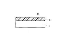
- the bonding structure 100 includes resin members 1 and 2 and an intermediate member 3 disposed between the resin members 1 and 2.
- the hatching of the resin members 1 and 2 is omitted for easy viewing.
- the resin members 1 and 2 are examples of the “first resin member” and the “second resin member” in the present invention, respectively.
- Resin members 1 and 2 are made of different materials, and have low affinity, for example. For this reason, the resin members 1 and 2 are joined via the intermediate member 3.
- the material of the resin members 1 and 2 is a thermoplastic resin.
- the resin member 2 is transmissive to, for example, a joining laser L1 (see FIG. 3) described later.
- thermoplastic resin examples include PVC (polyvinyl chloride), PS (polystyrene), AS (acrylonitrile styrene), ABS (acrylonitrile butadiene styrene), PMMA (polymethyl methacrylate).
- PVC polyvinyl chloride
- PS polystyrene
- AS acrylonitrile styrene
- ABS acrylonitrile butadiene styrene
- PMMA polymethyl methacrylate
- PE polyethylene
- PP polypropylene
- PC polycarbonate
- m-PPE modified polyphenylene ether
- PA6 polyamide 6
- PA66 polyamide 66
- POM polyacetal
- PET polyethylene terephthalate
- PBT Polybutylene terephthalate
- PSF polysulfone
- PAR polyarylate
- PEI polyetherimide
- PPS polyphenylene sulfide
- PES polyethersulfone
- PEEK polyeK
- PAI polyamideimide
- LCP liquid crystal polymer
- PVDC polyvinylidene chloride
- PTFE polytetrafluoroethylene
- PCTFE polychlorotrifluoroethylene
- PVDF polyvinylidene fluoride
- TPE thermoplastic elastomer
- examples of TPE include TPO (olefin-based), TPS (styrene-based), TPEE (ester-based), TPU (urethane-based), TPA (nylon-based), And TPVC (vinyl chloride type) is mentioned.
- a filler may be added to the resin members 1 and 2.
- the filler include inorganic fillers (glass fibers, inorganic salts, etc.), metal fillers, organic fillers, and carbon fibers.
- the intermediate member 3 is a thermoplastic resin, and the storage elastic modulus at 20 ° C. exceeds 500 MPa.
- the intermediate member 3 is provided to join the resin members 1 and 2 having low affinity, and is interposed between the resin members 1 and 2.
- the intermediate member 3 may be provided over the entire surface between the resin member 1 and the resin member 2 or may be provided partially.
- the storage elastic modulus is a value measured using a dynamic viscoelasticity measuring device (DMA) with the temperature set to 20 ° C. and the frequency set to 10 Hz.
- DMA dynamic viscoelasticity measuring device
- the intermediate member 3 is welded to the surface 11 of the resin member 1. That is, the intermediate member 3 has a high affinity with the resin member 1 to the extent that it can be welded to the resin member 1.
- the intermediate member 3 is welded to the surface 21 of the resin member 2. That is, the intermediate member 3 has a high affinity with the resin member 2 to the extent that it can be welded to the resin member 2.
- the intermediate member 3 has absorptivity with respect to the laser L1 for joining mentioned later, for example.
- the intermediate member 3 preferably has a linear expansion coefficient between the resin members 1 and 2.
- thermoplastic resin as the material of the intermediate member 3, PVC (polyvinyl chloride), PS (polystyrene), AS (acrylonitrile styrene), ABS (acrylonitrile butadiene styrene), PMMA (polymethyl methacrylate), PE (polyethylene), PP (polypropylene), PC (polycarbonate), m-PPE (modified polyphenylene ether), PA6 (polyamide 6), PA66 (polyamide 66), POM (polyacetal), PET (polyethylene terephthalate), PBT (poly) Butylene terephthalate), PSF (polysulfone), PAR (polyarylate), PEI (polyetherimide), PPS (polyphenylene sulfide), PES (polyethersulfone), PEEK (polyether) -Terketone), PAI (polyamideimide), LCP (liquid crystal polymer), PVDC (polyvinyl chloride
- a filler may be added to the intermediate member 3.
- the filler include inorganic fillers (glass fibers, inorganic salts, etc.), metal fillers, organic fillers, and carbon fibers.
- the intermediate member 3 is formed on the surface 11 of the resin member 1.
- the melted intermediate member 3 is laminated on the surface 11 of the resin member 1 by a hot melt laminating method using a 3D printer, and the melted intermediate member 3 is solidified, whereby the intermediate member 3 is solidified. Is welded to the surface 11 of the resin member 1.
- the intermediate member 3 and the resin member 2 are disposed adjacent to each other.
- the resin member 2 is disposed on the side opposite to the resin member 1 with respect to the intermediate member 3.
- the laser L1 for joining is irradiated toward the intermediate member 3 from the resin member 2 side.
- the resin member 2 is transmissive to the laser L1, and the intermediate member 3 is absorbent to the laser L1.
- Laser L1 is absorbed by the intermediate member 3, and the intermediate member 3 is heated. For this reason, the intermediate member 3 is melted and then solidified, so that the intermediate member 3 is welded to the surface 21 of the resin member 2.
- Laser L1 is, for example, a semiconductor laser.
- the joined structure 100 shown in FIG. 1 is manufactured. That is, in the joined structure 100, the resin member 1 and the intermediate member 3 are joined by welding, and the resin member 2 and the intermediate member 3 are joined by welding.
- the intermediate member 3 is melted and welded to the resin member 1, thereby joining the intermediate member 3 and the resin member 1, and the intermediate member 3 is melted to obtain the resin member. 2, a step of joining the intermediate member 3 and the resin member 2 is provided.
- the resin members 1 and 2 which are hard to weld by low affinity can be joined via the intermediate member 3.
- FIG. Thereby, the freedom degree of the combination of the material in joining of dissimilar materials can be improved.
- the intermediate member 3 having a storage elastic modulus at 20 ° C. exceeding 500 MPa it is possible to improve heat resistance, oil resistance and chemical resistance as compared with the case where a soft elastomer or the like is used as the intermediate member.
- the stress resulting from the linear expansion coefficient difference of the resin members 1 and 2 is relieve
- the bonding structure 100 a includes resin members 1 a and 2 and an intermediate member 3 disposed between the resin members 1 a and 2.
- the hatching of the resin members 1 a and 2 is omitted for easy viewing.
- the resin members 1a and 2 are examples of the “first resin member” and the “second resin member” in the present invention, respectively.
- Resin members 1a and 2 are made of different materials, and have low affinity, for example. For this reason, the resin members 1 a and 2 are joined via the intermediate member 3.
- the material of the resin member 1a is a thermoplastic resin or a thermosetting resin. Further, the resin member 1a may have a high affinity with the intermediate member 3 to the extent that it can be welded to the intermediate member 3, or may be difficult to weld with the intermediate member 3 and have a low affinity.
- thermoplastic resin as the material of the resin member 1a is the same as that of the resin member 1 described above.
- thermosetting resin as the material of the resin member 1a, EP (epoxy), PUR (polyurethane), UF (urea formaldehyde), MF (melamine formaldehyde), PF (phenol formaldehyde), UP (unsaturated) Polyester) and SI (silicone).
- EP epoxy
- PUR polyurethane
- UF urea formaldehyde
- MF melamine formaldehyde
- PF phenol formaldehyde
- UP unsaturated) Polyester
- SI silicone
- FRP fiber reinforced plastic
- a perforated portion 12a is formed on the surface 11a of the resin member 1a, and the intermediate member 3 is filled and solidified in the perforated portion 12a. For this reason, the resin member 1a and the intermediate member 3 are mechanically joined by the anchor effect.
- One or more perforations 12a may be provided.
- the perforated part 12a is an example of the “concave part” in the present invention.
- the perforated part 12a is a substantially circular non-through hole when seen in a plan view, and a plurality of perforated parts 12a are arranged on the surface 11a of the resin member 1a at a predetermined interval.
- a projecting portion 13a projecting inward is formed on the inner peripheral surface of the perforated portion 12a.
- the protrusion 13a is formed over the entire length in the circumferential direction, and is formed in an annular shape.
- the depth of the perforated part 12a is preferably 0.03 mm or more in order to ensure the bonding strength.
- the diameter of the perforated part 12a can be arbitrarily set within a range where an anchor effect can be obtained.
- the perforated portion 12a is formed by, for example, a processing laser L2 (see FIG. 5).
- the type of laser L2 is preferably a laser capable of pulse oscillation, and includes fiber laser, YAG laser, YVO 4 laser, semiconductor laser, carbon dioxide laser, excimer laser, ultraviolet laser, picosecond laser, and femtosecond laser. Can do.
- Such a perforated part 12a is formed by a laser L2 in which one pulse is composed of a plurality of sub-pulses.
- This laser L2 is suitable for forming the perforated portion 12a because energy can be easily concentrated in the depth direction.
- fiber laser marker MX-Z2000 or MX-Z2050 manufactured by OMRON there can be mentioned fiber laser marker MX-Z2000 or MX-Z2050 manufactured by OMRON.
- one period of the sub-pulse is 15 ns or less. This is because when one period of the sub-pulse exceeds 15 ns, energy is easily diffused due to heat conduction, and it becomes difficult to form the perforated portion 12a.
- one cycle of the subpulse is a total time of the irradiation time for one subpulse and the interval from the end of the irradiation of the subpulse to the start of the irradiation of the next subpulse.
- the number of subpulses in one pulse is preferably 2 or more and 50 or less. This is because when the number of sub-pulses exceeds 50, the output per unit of sub-pulses becomes small and it becomes difficult to form the perforated part 12a.
- the other structure of the bonded structure 100a is the same as that of the bonded structure 100 described above.
- the surface 11a of the resin member 1a is irradiated with a processing laser L2 to form a perforated portion 12a on the surface 11a of the resin member 1a.
- the processing laser L2 is, for example, a fiber laser, and one pulse is composed of a plurality of subpulses.
- the intermediate member 3 is formed on the surface 11a of the resin member 1a.
- the melted intermediate member 3 is filled in the perforated portion 12a of the resin member 1a by the hot melt lamination method using a 3D printer, and is laminated on the surface 11a of the resin member 1a and melted.
- the intermediate member 3 is solidified. Thereby, since the intermediate member 3 is embedded in the perforated part 12a, the resin member 1a and the intermediate member 3 are mechanically joined by the anchor effect.
- the intermediate member 3 and the resin member 2 are disposed adjacent to each other.
- the resin member 2 is arrange
- the laser L1 for joining is irradiated toward the intermediate member 3 from the resin member 2 side.
- the resin member 2 is transmissive to the laser L1, and the intermediate member 3 is absorbent to the laser L1.
- Laser L1 is absorbed by the intermediate member 3, and the intermediate member 3 is heated. For this reason, the intermediate member 3 is melted and then solidified, so that the intermediate member 3 is welded to the surface 21 of the resin member 2.
- Laser L1 is, for example, a semiconductor laser.
- the joined structure 100a shown in FIG. 4 is manufactured. That is, in the bonded structure 100a, the resin member 1a and the intermediate member 3 are bonded by the anchor effect, and the resin member 2 and the intermediate member 3 are bonded by welding.
- the resin member 1a and the intermediate member 3 may be joined by welding in addition to the anchor effect.
- the perforated portion 12a is formed on the surface 11a of the resin member 1a, the intermediate member 3 is melted and filled into the perforated portion 12a.
- a step of joining by the anchor effect and a step of joining the intermediate member 3 and the resin member 2 by melting the intermediate member 3 and welding it to the resin member 2.
- the anchor effect can be improved by forming the protruding portion 13a in the perforated portion 12a.
- the resin member 1a and the intermediate member 3 may be welded.
- the bonding strength between the resin member 1a and the intermediate member 3 can be improved.
- the intermediate member 3 having a storage elastic modulus at 20 ° C. exceeding 500 MPa it is possible to improve heat resistance, oil resistance and chemical resistance as compared with the case where a soft elastomer or the like is used as the intermediate member.
- the stress resulting from the linear expansion coefficient difference of the resin members 1a and 2 is relieved by the intermediate member 3 because the linear expansion coefficient of the intermediate member 3 is between the resin members 1a and 2. Can do.
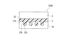
- the joining structure 100b includes a metal member 1b and a resin member 2, and an intermediate member 3 disposed between the metal member 1b and the resin member 2, as shown in FIG. In FIG. 8, the metal member 1b and the resin member 2 are not hatched in consideration of easy viewing.
- the metal member 1b and the resin member 2 are joined via the intermediate member 3.
- the material of the metal member 1b include iron-based metal, stainless-based metal, copper-based metal, aluminum-based metal, magnesium-based metal, and alloys thereof.
- a metal molding may be sufficient and zinc die-casting, aluminum die-casting, powder metallurgy, etc. may be sufficient.
- a perforated portion 12b is formed on the surface 11b of the metal member 1b, and the intermediate member 3 is filled and solidified in the perforated portion 12b. For this reason, the resin member 1b and the intermediate member 3 are mechanically joined by the anchor effect.
- the perforated part 12b is configured in the same manner as the perforated part 12a described above.
- the perforated part 12b is an example of the “concave part” in the present invention.
- the other structure of the bonded structure 100b is the same as the bonded structure 100a described above.
- the manufacturing method of the joined structure 100b is the same as that of the second embodiment.
- the perforated portion 12b is formed on the surface 11b of the metal member 1b, the intermediate member 3 is melted and filled in the perforated portion 12b.
- a step of joining by the anchor effect and a step of joining the intermediate member 3 and the resin member 2 by melting the intermediate member 3 and welding it to the resin member 2.
- the metal member 1b and the resin member 2 can be joined via the intermediate member 3.
- the anchor effect can be improved by forming the protruding portion 13b in the perforated portion 12b.
- the intermediate member 3 having a storage elastic modulus at 20 ° C. exceeding 500 MPa it is possible to improve heat resistance, oil resistance and chemical resistance as compared with the case where a soft elastomer or the like is used as the intermediate member.
- the deterioration of the resin member 2 is suppressed by using a material having corrosion resistance as the material of the intermediate member 3. can do.
- the stress caused by the difference in linear expansion coefficient between the metal member 1 b and the resin member 2 is applied to the intermediate member 3. Can be relaxed.
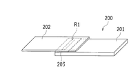
- the resin member 201 is formed in a plate shape, has a length of 100 mm, a width of 17.5 mm, and a thickness of 2 to 3 mm.
- the resin member 201 is not formed with a perforated portion unlike Example 2 described later.
- the intermediate member 203 was formed on the surface of the resin member 201.
- This intermediate member 203 is ABS (acrylonitrile butadiene styrene), and was formed using a 3D printer. For this reason, the intermediate member 203 is welded to the surface of the resin member 201.
- the intermediate member 203 has a length of 5 mm, a width of 15 mm, and a thickness of 0.5 mm.
- the intermediate member 203 and the resin member 202 are disposed adjacent to each other.
- the resin member 202 PMMA (polymethyl methacrylate) was used.
- the resin member 202 is formed in a plate shape, has a length of 100 mm, a width of 17.5 mm, and a thickness of 1 mm.
- the intermediate member 203 and the resin member 202 were welded by irradiating the bonding region R1 between the intermediate member 203 and the resin member 202 with a laser for bonding.
- the joining region R1 is a linear region having a length of 10 mm and a width of 1 mm, and is provided so as to extend in the width direction of the intermediate member 203.
- the resin member 202 is transparent to the bonding laser, and the intermediate member 203 is absorbable to the bonding laser.
- the bonding laser is on the resin member 202 side.
- the irradiation conditions of the laser for joining are as follows.
- resin members 201 and 202 were laminated and irradiated with a semiconductor laser without interposing intermediate member 203, but they were not joined. This is probably because PBT and PMMA have low affinity.
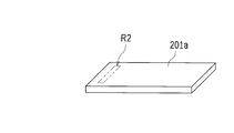
- PBT was used as the resin member 201a.
- the shape of the resin member 201a is the same as that of the resin member 201 of the first embodiment.
- region R2 of the surface of the resin member 201a was irradiated with the laser for a process, and the some perforation part (illustration omitted) was formed in the process area
- the processing region R2 is a region substantially corresponding to the region irradiated with the bonding laser.
- the intermediate member 203 was welded to the surface of the resin member 201a, and the resin member 202 was welded to the intermediate member 203.
- the resin member 202 is PMMA, and the intermediate member is ABS.
- the joined structure 200a of Example 2 was produced. That is, the second embodiment is different from the first embodiment in that a perforated portion is formed in the resin member 201a.
- the resin member 201a and the intermediate member 203 are welded over the entire surface of the intermediate member 203, and the resin member 202 and the intermediate member 203 are welded in the bonding region R1.
- the resin member 201a and the intermediate member 203 are mechanically joined to each other by the anchor effect by filling the perforated portion provided in the processing region R2 with the intermediate member 203.
- SUS was used as the metal member 201b.
- the shape of the metal member 201b is the same as that of the resin member 201 of the first embodiment.
- Example 2 a plurality of perforations (not shown) were formed in the processing area.
- the processing region is a region substantially corresponding to the region irradiated with the bonding laser.
- an intermediate member 203 was formed on the surface of the metal member 201b, and a resin member 202 was welded to the intermediate member 203.
- the resin member 202 is PMMA, and the intermediate member 203 is ABS.
- the joined structure 200b of Example 3 was produced. That is, the third embodiment is different from the second embodiment in that one of the objects to be joined is the metal member 201b.
- the metal member 201b and the intermediate member 203 are mechanically bonded to each other by the anchor effect by filling the perforated portion provided in the processing region with the intermediate member 203, and the resin member 202 and the intermediate structure 203b.
- the member 203 is welded at the joining region R1.
- the metal member 201b and the resin member 202 without the perforated part were laminated and irradiated with the semiconductor laser without interposing the intermediate member 203, but they were not joined.
- the bonding strength was measured for the bonded structures 200, 200a, and 200b. Specifically, using a digital force gauge manufactured by Imada, a test was performed at a tensile speed of 5 mm / min in the shear direction, and the test was terminated by peeling off the bonding interface. And the maximum intensity
- the bonding structure 200 of Example 1 had a bonding strength of 5.6 MPa.
- the intermediate member 203 is interposed, so that the resin members 201 and 202 that are difficult to weld can be bonded and sufficient bonding strength can be secured.
- the joint structure 200a of Example 2 had a joint strength of 7.4 MPa. That is, in the joint structure 200a according to the second embodiment, by forming a perforated portion in the resin member 201a, the intermediate member 203 is filled into the perforated portion and the intermediate member 203 and the resin member 201a are joined also by the anchor effect. Therefore, it was possible to improve the bonding strength.
- the joint structure 200b of Example 3 had a joint strength of 6.9 MPa. That is, in the joint structure 200b according to Example 3, by interposing the intermediate member 203, the metal member 201b and the resin member 202 were joined, and sufficient joint strength could be secured.
- the intermediate member 3 is welded to the surface 11 of the resin member 1 using a 3D printer.
- the present invention is not limited thereto, and the surface of the resin member 1 is formed by injection molding or hot press molding. 11 may be welded with the intermediate member 3.
- the second and third embodiments are identical to the second and third embodiments.
- the example which welds the intermediate member 3 to the surface 21 of the resin member 2 by irradiating the laser L1 was shown, it is not restricted to this,
- the surface of the resin member 2 is formed by hot press molding.
- the intermediate member 3 may be welded to 21.
- the resin member 2 does not have to be transmissive to the laser L1, and the intermediate member 3 does not have to be absorbent to the laser L1.
- the second and third embodiments are the same applies to the second and third embodiments.
- the resin member 1 and the intermediate member 3 after welding the resin member 1 and the intermediate member 3, the example which welds the resin member 2 and the intermediate member 3 was shown, but it is not restricted to this, The resin member 2 and the intermediate member 3 are shown. Alternatively, the resin member 1 and the intermediate member 3 may be welded. In this case, as a method of welding the resin member 2 and the intermediate member 3, 3D printing, injection molding, and hot press molding are mentioned. Moreover, as a method of welding the intermediate member 3 and the resin member 1 to which the resin member 2 is bonded, there are laser L1 irradiation and hot press molding. The same applies to the second and third embodiments.
- the resin members 1 and 2 may be welded to the intermediate member 3 at the same time.
- the welding method in this case include laser L1 irradiation and hot press molding.
- at least one of the resin members 1 and 2 is transmissive to the laser L1, and the intermediate member 3 is absorbent to the laser L1.
- the resin members 1 and 2 and the intermediate member 3 may have any laser transmittance. The same applies to the second and third embodiments.
- the perforated part 12a was formed in the surface 11a of the resin member 1a was shown, not only this but the groove-shaped recessed part may be formed in the surface of the resin member. Moreover, although the example in which the protrusion part 13a is formed in the perforated part 12a was shown, not only this but the perforated part may be formed in the cylindrical shape or the mortar shape. Moreover, although the example which forms the perforated part 12a with the laser L2 for a process was shown, you may make it form a recessed part by other roughening processes, such as not only this but blasting. The same applies to the third embodiment.
- the present invention is applicable to a method for manufacturing a joined structure in which different members are joined via an intermediate member, and the joined structure.
Abstract
L'invention concerne un procédé de fabrication pour un corps structural assemblé dans lequel un premier élément de résine et un second élément de résine sont assemblés à l'aide d'un élément intermédiaire fabriqué en résine. Le procédé de fabrication consiste à coller par fusion l'élément intermédiaire au premier élément de résine, assemblant ainsi l'élément intermédiaire et le premier élément de résine, ou à assembler l'élément intermédiaire et le premier élément de résine par effet d'ancrage en formant une partie évidée sur la surface du premier élément en résine; à faire fondre l'élément intermédiaire, et à remplir la partie évidée avec l'élément intermédiaire fondu; et à coller par fusion l'élément intermédiaire au second élément de résine, assemblant ainsi l'élément intermédiaire et le second élément de résine.
Applications Claiming Priority (2)
| Application Number | Priority Date | Filing Date | Title |
|---|---|---|---|
| JP2015020152A JP2016141092A (ja) | 2015-02-04 | 2015-02-04 | 接合構造体の製造方法および接合構造体 |
| JP2015-020152 | 2015-02-04 |
Publications (1)
| Publication Number | Publication Date |
|---|---|
| WO2016125594A1 true WO2016125594A1 (fr) | 2016-08-11 |
Family
ID=56563945
Family Applications (1)
| Application Number | Title | Priority Date | Filing Date |
|---|---|---|---|
| PCT/JP2016/051728 WO2016125594A1 (fr) | 2015-02-04 | 2016-01-21 | Procédé de fabrication pour un corps structural assemblé et corps structural assemblé |
Country Status (2)
| Country | Link |
|---|---|
| JP (1) | JP2016141092A (fr) |
| WO (1) | WO2016125594A1 (fr) |
Cited By (4)
| Publication number | Priority date | Publication date | Assignee | Title |
|---|---|---|---|---|
| EP3184283A4 (fr) * | 2014-08-22 | 2018-04-18 | Omron Corporation | Procédé de fabrication de structure de collage et structure de collage |
| EP3466290A1 (fr) * | 2017-10-04 | 2019-04-10 | adidas AG | Article de sport composite |
| US11191319B2 (en) | 2017-10-04 | 2021-12-07 | Adidas Ag | Composite sports article |
| US11904553B2 (en) * | 2018-09-28 | 2024-02-20 | Lg Chem, Ltd. | Method for producing joined body of different materials and joined body of different materials |
Families Citing this family (2)
| Publication number | Priority date | Publication date | Assignee | Title |
|---|---|---|---|---|
| KR102118938B1 (ko) * | 2018-06-04 | 2020-06-04 | 동국대학교 경주캠퍼스 산학협력단 | 이종 접합 부재 및 그의 제조방법 |
| JP7298486B2 (ja) | 2020-01-17 | 2023-06-27 | トヨタ自動車株式会社 | 高圧タンクの製造方法及び高圧タンク |
Citations (3)
| Publication number | Priority date | Publication date | Assignee | Title |
|---|---|---|---|---|
| JP2008007584A (ja) * | 2006-06-28 | 2008-01-17 | Okayama Prefecture | 異種部材の接合方法及び異種部材接合品 |
| JP2009173023A (ja) * | 2007-12-25 | 2009-08-06 | Hayakawa Rubber Co Ltd | レーザー接合用シート及びそれを用いた接合方法 |
| JP2011143539A (ja) * | 2010-01-12 | 2011-07-28 | Nippon Light Metal Co Ltd | アルミニウム合金板と樹脂部材とのレーザー接合方法 |
-
2015
- 2015-02-04 JP JP2015020152A patent/JP2016141092A/ja active Pending
-
2016
- 2016-01-21 WO PCT/JP2016/051728 patent/WO2016125594A1/fr active Application Filing
Patent Citations (3)
| Publication number | Priority date | Publication date | Assignee | Title |
|---|---|---|---|---|
| JP2008007584A (ja) * | 2006-06-28 | 2008-01-17 | Okayama Prefecture | 異種部材の接合方法及び異種部材接合品 |
| JP2009173023A (ja) * | 2007-12-25 | 2009-08-06 | Hayakawa Rubber Co Ltd | レーザー接合用シート及びそれを用いた接合方法 |
| JP2011143539A (ja) * | 2010-01-12 | 2011-07-28 | Nippon Light Metal Co Ltd | アルミニウム合金板と樹脂部材とのレーザー接合方法 |
Cited By (5)
| Publication number | Priority date | Publication date | Assignee | Title |
|---|---|---|---|---|
| EP3184283A4 (fr) * | 2014-08-22 | 2018-04-18 | Omron Corporation | Procédé de fabrication de structure de collage et structure de collage |
| US10471660B2 (en) | 2014-08-22 | 2019-11-12 | Omron Corporation | Manufacturing method of bonding structure and bonding structure |
| EP3466290A1 (fr) * | 2017-10-04 | 2019-04-10 | adidas AG | Article de sport composite |
| US11191319B2 (en) | 2017-10-04 | 2021-12-07 | Adidas Ag | Composite sports article |
| US11904553B2 (en) * | 2018-09-28 | 2024-02-20 | Lg Chem, Ltd. | Method for producing joined body of different materials and joined body of different materials |
Also Published As
| Publication number | Publication date |
|---|---|
| JP2016141092A (ja) | 2016-08-08 |
Similar Documents
| Publication | Publication Date | Title |
|---|---|---|
| WO2016125594A1 (fr) | Procédé de fabrication pour un corps structural assemblé et corps structural assemblé | |
| TWI659845B (zh) | 接合構造體的製造方法以及接合構造體 | |
| WO2016027775A1 (fr) | Structure de jonction et procédé pour fabriquer une structure de jonction | |
| JP6414477B2 (ja) | 接合構造体の製造方法 | |
| JP6439455B2 (ja) | 接合構造体の製造方法 | |
| TWI704994B (zh) | 接合構造體的製造方法及接合構造體 | |
| JP6459930B2 (ja) | 接合構造体の製造方法および接合構造体 | |
| WO2016129392A1 (fr) | Procédé de production d'une structure liée, et structure liée | |
| WO2016133079A1 (fr) | Procédé de production d'une structure assemblée, et structure assemblée | |
| WO2016140097A1 (fr) | Procédé d'assemblage, procédé de production d'une structure assemblée, et structure assemblée | |
| JP6432364B2 (ja) | 接合構造体の製造方法 | |
| WO2016143585A1 (fr) | Procédé d'usinage, procédé de production de structure assemblée et structure assemblée | |
| WO2016117504A1 (fr) | Procédé de production de structure de raccordement, et structure de raccordement | |
| WO2016117501A1 (fr) | Procédé de soudage au laser et structure assemblée | |
| WO2016140096A1 (fr) | Structure d'assemblage | |
| WO2016140052A1 (fr) | Procédé permettant le traitement au laser d'un élément métallique, et structure réunie produite à l'aide dudit procédé | |
| KR102603133B1 (ko) | 접합 구조체, 및 그 접합 구조체를 구비하는 스위치, 광전 센서 및 근접 센서 | |
| WO2022185739A1 (fr) | Procédé de production d'une jonction et jonction |
Legal Events
| Date | Code | Title | Description |
|---|---|---|---|
| 121 | Ep: the epo has been informed by wipo that ep was designated in this application |
Ref document number: 16746425 Country of ref document: EP Kind code of ref document: A1 |
|
| NENP | Non-entry into the national phase |
Ref country code: DE |
|
| 122 | Ep: pct application non-entry in european phase |
Ref document number: 16746425 Country of ref document: EP Kind code of ref document: A1 |