WO2016125332A1 - 車体外部移動物体検知システム - Google Patents
車体外部移動物体検知システム Download PDFInfo
- Publication number
- WO2016125332A1 WO2016125332A1 PCT/JP2015/075361 JP2015075361W WO2016125332A1 WO 2016125332 A1 WO2016125332 A1 WO 2016125332A1 JP 2015075361 W JP2015075361 W JP 2015075361W WO 2016125332 A1 WO2016125332 A1 WO 2016125332A1
- Authority
- WO
- WIPO (PCT)
- Prior art keywords
- moving object
- object detection
- movable part
- video
- vehicle body
- Prior art date
- Legal status (The legal status is an assumption and is not a legal conclusion. Google has not performed a legal analysis and makes no representation as to the accuracy of the status listed.)
- Ceased
Links
Images










Classifications
-
- H—ELECTRICITY
- H04—ELECTRIC COMMUNICATION TECHNIQUE
- H04N—PICTORIAL COMMUNICATION, e.g. TELEVISION
- H04N7/00—Television systems
- H04N7/18—Closed-circuit television [CCTV] systems, i.e. systems in which the video signal is not broadcast
- H04N7/188—Capturing isolated or intermittent images triggered by the occurrence of a predetermined event, e.g. an object reaching a predetermined position
-
- B—PERFORMING OPERATIONS; TRANSPORTING
- B60—VEHICLES IN GENERAL
- B60R—VEHICLES, VEHICLE FITTINGS, OR VEHICLE PARTS, NOT OTHERWISE PROVIDED FOR
- B60R11/00—Arrangements for holding or mounting articles, not otherwise provided for
- B60R11/04—Mounting of cameras operative during drive; Arrangement of controls thereof relative to the vehicle
-
- E—FIXED CONSTRUCTIONS
- E02—HYDRAULIC ENGINEERING; FOUNDATIONS; SOIL SHIFTING
- E02F—DREDGING; SOIL-SHIFTING
- E02F9/00—Component parts of dredgers or soil-shifting machines, not restricted to one of the kinds covered by groups E02F3/00 - E02F7/00
- E02F9/26—Indicating devices
- E02F9/261—Surveying the work-site to be treated
-
- G—PHYSICS
- G06—COMPUTING OR CALCULATING; COUNTING
- G06T—IMAGE DATA PROCESSING OR GENERATION, IN GENERAL
- G06T7/00—Image analysis
- G06T7/20—Analysis of motion
- G06T7/254—Analysis of motion involving subtraction of images
-
- G—PHYSICS
- G06—COMPUTING OR CALCULATING; COUNTING
- G06V—IMAGE OR VIDEO RECOGNITION OR UNDERSTANDING
- G06V10/00—Arrangements for image or video recognition or understanding
- G06V10/20—Image preprocessing
- G06V10/25—Determination of region of interest [ROI] or a volume of interest [VOI]
-
- G—PHYSICS
- G06—COMPUTING OR CALCULATING; COUNTING
- G06V—IMAGE OR VIDEO RECOGNITION OR UNDERSTANDING
- G06V20/00—Scenes; Scene-specific elements
- G06V20/50—Context or environment of the image
- G06V20/56—Context or environment of the image exterior to a vehicle by using sensors mounted on the vehicle
- G06V20/58—Recognition of moving objects or obstacles, e.g. vehicles or pedestrians; Recognition of traffic objects, e.g. traffic signs, traffic lights or roads
-
- G—PHYSICS
- G06—COMPUTING OR CALCULATING; COUNTING
- G06V—IMAGE OR VIDEO RECOGNITION OR UNDERSTANDING
- G06V40/00—Recognition of biometric, human-related or animal-related patterns in image or video data
- G06V40/10—Human or animal bodies, e.g. vehicle occupants or pedestrians; Body parts, e.g. hands
- G06V40/103—Static body considered as a whole, e.g. static pedestrian or occupant recognition
-
- G—PHYSICS
- G08—SIGNALLING
- G08G—TRAFFIC CONTROL SYSTEMS
- G08G1/00—Traffic control systems for road vehicles
- G08G1/16—Anti-collision systems
- G08G1/166—Anti-collision systems for active traffic, e.g. moving vehicles, pedestrians, bikes
-
- H—ELECTRICITY
- H04—ELECTRIC COMMUNICATION TECHNIQUE
- H04N—PICTORIAL COMMUNICATION, e.g. TELEVISION
- H04N23/00—Cameras or camera modules comprising electronic image sensors; Control thereof
- H04N23/90—Arrangement of cameras or camera modules, e.g. multiple cameras in TV studios or sports stadiums
-
- B—PERFORMING OPERATIONS; TRANSPORTING
- B60—VEHICLES IN GENERAL
- B60Q—ARRANGEMENT OF SIGNALLING OR LIGHTING DEVICES, THE MOUNTING OR SUPPORTING THEREOF OR CIRCUITS THEREFOR, FOR VEHICLES IN GENERAL
- B60Q9/00—Arrangement or adaptation of signal devices not provided for in one of main groups B60Q1/00 - B60Q7/00, e.g. haptic signalling
- B60Q9/008—Arrangement or adaptation of signal devices not provided for in one of main groups B60Q1/00 - B60Q7/00, e.g. haptic signalling for anti-collision purposes
-
- B—PERFORMING OPERATIONS; TRANSPORTING
- B60—VEHICLES IN GENERAL
- B60W—CONJOINT CONTROL OF VEHICLE SUB-UNITS OF DIFFERENT TYPE OR DIFFERENT FUNCTION; CONTROL SYSTEMS SPECIALLY ADAPTED FOR HYBRID VEHICLES; ROAD VEHICLE DRIVE CONTROL SYSTEMS FOR PURPOSES NOT RELATED TO THE CONTROL OF A PARTICULAR SUB-UNIT
- B60W2420/00—Indexing codes relating to the type of sensors based on the principle of their operation
- B60W2420/40—Photo, light or radio wave sensitive means, e.g. infrared sensors
- B60W2420/403—Image sensing, e.g. optical camera
-
- G—PHYSICS
- G06—COMPUTING OR CALCULATING; COUNTING
- G06T—IMAGE DATA PROCESSING OR GENERATION, IN GENERAL
- G06T2207/00—Indexing scheme for image analysis or image enhancement
- G06T2207/10—Image acquisition modality
- G06T2207/10016—Video; Image sequence
-
- G—PHYSICS
- G06—COMPUTING OR CALCULATING; COUNTING
- G06T—IMAGE DATA PROCESSING OR GENERATION, IN GENERAL
- G06T2207/00—Indexing scheme for image analysis or image enhancement
- G06T2207/30—Subject of image; Context of image processing
- G06T2207/30248—Vehicle exterior or interior
- G06T2207/30252—Vehicle exterior; Vicinity of vehicle
-
- G—PHYSICS
- G06—COMPUTING OR CALCULATING; COUNTING
- G06T—IMAGE DATA PROCESSING OR GENERATION, IN GENERAL
- G06T2207/00—Indexing scheme for image analysis or image enhancement
- G06T2207/30—Subject of image; Context of image processing
- G06T2207/30248—Vehicle exterior or interior
- G06T2207/30252—Vehicle exterior; Vicinity of vehicle
- G06T2207/30261—Obstacle
-
- G—PHYSICS
- G06—COMPUTING OR CALCULATING; COUNTING
- G06V—IMAGE OR VIDEO RECOGNITION OR UNDERSTANDING
- G06V2201/00—Indexing scheme relating to image or video recognition or understanding
- G06V2201/08—Detecting or categorising vehicles
-
- G—PHYSICS
- G08—SIGNALLING
- G08B—SIGNALLING SYSTEMS, e.g. PERSONAL CALLING SYSTEMS; ORDER TELEGRAPHS; ALARM SYSTEMS
- G08B21/00—Alarms responsive to a single specified undesired or abnormal condition and not otherwise provided for
- G08B21/18—Status alarms
- G08B21/22—Status alarms responsive to presence or absence of persons
Definitions
- the present invention relates to a vehicle body externally moving object detection system.
- the vehicle Behavior estimation means for estimating a behavior parameter representing the behavior of the vehicle for each of the plurality of images, and the behavior used for detecting objects around the vehicle based on the plurality of the behavior parameters estimated for each of the plurality of images.
- an image processing apparatus including a setting unit that sets a parameter, and an object detection unit that detects an object around the vehicle using the behavior parameter set by the setting unit and the plurality of images (for example, Patent Document 1).
- the image processing apparatus described above includes a traveling direction detection unit that determines the traveling direction of the vehicle from the vehicle gear and the steering angle, and a monitoring unit that is provided for each of a plurality of cameras attached to the vehicle based on the detection result of the traveling direction detection unit.
- a setting unit that selects an appropriate monitoring unit from the above, a behavior estimation unit in the monitoring unit that estimates the behavior of the host vehicle based on the acquired camera video, a road surface estimation unit in the monitoring unit that estimates the road surface, And an obstacle detection unit in the monitoring unit for detecting the obstacle.
- the setting unit acquires the estimated information from the commanded monitoring unit and transmits it to each monitoring unit.
- the obstacle detection unit in the monitoring unit detects the obstacle based on the estimated information received from the setting unit and the image supplied from each camera. As a result, it is possible to improve the detection accuracy of objects around the vehicle.
- a large construction machine such as a dump truck for a mine has a vehicle body structure such as a vehicle body and tires that are larger in size than a general vehicle, and the structure of the vehicle body is complicated.
- the road surface portion and the own vehicle structure for example, a vessel, a tire, etc.
- the movement direction and the movement amount of the tire movement reflected in the video and the apparent movement of the road surface are different. Since the tire is attached to the shaft of the host vehicle, the tire exists at substantially the same position in the image, but the surface of the tire rotates. In addition, when the host vehicle turns right or left, the tire tilts to the right or left. On the other hand, the road surface apparently moves in accordance with the movement of the host vehicle. When the host vehicle is moving forward, the road surface moves from the right to the left in the image by the camera attached in the left direction of the host vehicle.
- the above-described image processing apparatus employs a moving stereo system that detects the three-dimensional position of an object by comparing the image one frame before and the current image, and estimates the road surface from the measurement result. Then, an object occupying a certain position in the image is detected as an obstacle on the estimated road surface coordinate system.
- this image processing apparatus is employed in the construction machine described above, it is calculated that the tire is located at a position different from the road surface, so that the tire may be erroneously detected as an obstacle and notified to the operator.
- the present invention has been made on the basis of the above-mentioned matters, and its object is to detect a moving object outside a vehicle body that detects a moving object in a region excluding the movable region of the movable structure of the host vehicle from surrounding images.
- a detection system is provided.
- the present application includes a plurality of means for solving the above-described problems.
- a surrounding video input unit that captures a video of the surroundings of the host vehicle and transmits the video as a surrounding video, and a result output of the moving object detection are output.
- a vehicle body external moving object detection system comprising: a composite video constructing unit that constructs a composite video including the composite video from the surrounding video; and an output unit that presents the composite video to a user.
- a movable part region setting unit that sets the shape and arrangement of the movable part and calculates a region of the movable part of the host vehicle, the movable part region calculated by the movable part region setting unit, and the surrounding video from the surrounding video input unit
- a moving object detection unit that performs detection processing of a moving object on an area obtained by removing the movable part area from the surrounding image and outputs a detection result.
- the moving object is detected in the area excluding the movable area of the movable structure of the own vehicle from the surrounding image, the erroneous detection of the movable structure of the own vehicle can be prevented and the user can It is possible to prevent the detection target object from being overlooked in the vicinity of the own vehicle, which is a part that should be most carefully paid when operating the own vehicle. Thereby, the user can acquire only the moving object detection result required for work. As a result, the operational efficiency of the entire work can be improved.
- 1 is a side view showing a dump truck provided with a first embodiment of a vehicle body externally moving object detection system of the present invention. It is a conceptual diagram explaining arrangement
- 1 is a block diagram showing a configuration of a first embodiment of a vehicle body externally moving object detection system of the present invention. It is a flowchart figure which shows the processing content in 1st Embodiment of the vehicle body exterior moving object detection system of this invention.
- FIG. 1 is a side view showing a dump truck provided with a first embodiment of a vehicle body externally moving object detection system of the present invention.
- a dump truck (own vehicle) 1 shown in FIG. 1 includes a vehicle body 2 formed with a sturdy frame structure, a vessel (loading platform) 3 mounted on the vehicle body 2 so as to be able to undulate, and a left front wheel mounted on the vehicle body 2.
- 4A (L) and left rear wheel 4B (L) are mainly provided.
- the vehicle body 2 is provided with an engine (not shown) that drives the rear wheels 4B.
- the engine has, for example, an engine control device (hereinafter referred to as ECU), and the number of revolutions thereof is controlled by controlling the flow rate of fuel supplied by a command signal from the ECU.
- ECU engine control device
- the vessel 3 is a container provided to load a load such as a crushed stone, and is connected to the vehicle body 2 via a pin coupling portion 5 so as to be raised and lowered.
- Two undulation cylinders 6 are installed at a lower portion of the vessel 3 with a predetermined interval in the width direction of the vehicle. When pressure oil is supplied to and discharged from the undulation cylinder 6, the undulation cylinder 6 extends and contracts, and the vessel 3 is undulated.
- a collar portion 7 is provided on the upper front side of the vessel 3.
- the heel portion 7 has a function of protecting the cab 8 installed on the lower side thereof (that is, the front portion of the vehicle body 2) from scattered objects such as rocks and protecting the cab 8 when the vehicle falls. Yes.
- a vehicle body external moving object detection device 100 inside the cab 8, a vehicle body external moving object detection device 100 (see FIG. 4), a steering handle (not shown), an accelerator pedal, and a brake pedal, which are control devices constituting the vehicle external movement object detection system. Etc. (not shown).
- FIG. 2 is a conceptual diagram illustrating the arrangement of cameras constituting the surrounding image input unit in the first embodiment of the vehicle body external moving object detection system of the present invention
- FIG. 3 is a diagram of the vehicle body external moving object detection system of the present invention. It is a conceptual diagram which shows the image
- a front camera 301 that captures the front of the dump truck 1 at a wide angle and a rear camera 303 that captures the rear of the dump truck 1 at a wide angle are provided on the front and rear sides of the vehicle body 2 of the dump truck 1.
- a left direction camera 302 that captures the left direction of the dump truck 1 with a wide angle and a right direction camera 304 that captures the right direction of the dump truck 1 with a wide angle are provided on the left side surface and the right side surface of the vehicle body 2.
- These cameras 301 to 304 are attached with a depression angle on each surface of the vehicle body 2 so that the respective ground surfaces can be mainly photographed.
- a right front wheel 4A (R), a right rear wheel 4B (R), a left front wheel 4A (L), and a left rear wheel 4B (L) are mounted on the vehicle body 2 of the dump truck 1.
- FIG. 3 shows an example of surrounding images taken by these cameras 301-303.
- Reference numeral 401 denotes an example of a front image captured by the front camera 301.
- Reference numeral 402 denotes an example of a left direction image captured by the left direction camera 302.
- Reference numeral 403 denotes an example of a rear image taken by the rear camera 303.
- Reference numeral 404 denotes an example of a right direction image captured by the right direction camera 304.
- the surrounding images 401 to 404 are each taken at a wide angle, the horizon projected on the far side, that is, the upper part of each image appears curved. Also, a part of the vehicle body 2 is shown in the vicinity, that is, in the lower part of each image. For example, a part of the front portion of the vehicle body 2 is shown in the front image 401, and a left side portion of the vehicle body 2 and the left front wheel 4A (L) and the left rear wheel 4B (L) are shown in the left direction image 402, respectively. Yes.
- the right direction image 404 shows the right side portion of the vehicle body 2 and the right front wheel 4A (R) and the right rear wheel 4B (R), and the rear image 403 shows the rear portion of the vehicle body 2 and the left rear wheel 4B (L). Part of the vessel 3 of the host vehicle 1 is shown on the right rear wheel 4B (R) and in the upper part of the video.
- the distortion is particularly large at the edge of the image, such as where the vessel 3 is reflected. Moreover, the same wheel may be reflected on a plurality of cameras.
- a combination of the front video 401, the left video 402, the rear video 403, and the right video 404 is the surrounding video in this embodiment.
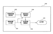
- FIG. 4 is a block diagram showing the configuration of the first embodiment of the vehicle body external moving object detection system of the present invention.
- the first embodiment of the vehicle body outside moving object detection system includes a vehicle body outside moving object detection device 100.
- the vehicle body outside moving object detection device 100 includes a surrounding image input unit 101, a composite image construction unit 102, a movable region setting unit 103, a moving object detection unit 104, and an output unit 105.
- the ambient video input unit 101 includes a plurality of cameras 301 to 304 that respectively capture the situation around the dump truck 1.
- the surrounding image input unit 101 transmits a plurality of surrounding images 401 to 404 that are photographing results to the composite image constructing unit 102 and the moving object detecting unit 104.
- the composite video construction unit 102 inputs a plurality of surrounding images 401 to 404 transmitted from the surrounding image input unit 101 and a detection position coordinate signal indicating the position of the moving object from the moving object detection unit 104.
- the composite video constructing unit 102 cuts out a necessary portion from the surrounding video input to generate the composite video, performs synthesis after coordinate conversion, and extracts detection position detection results of the moving object based on the input detection position coordinates.
- the video is synthesized, and the obtained synthesized video is sent to the output unit 105.
- the movable area setting unit 103 holds information on the positional relationship of the movable part of the host vehicle 1, and when the movable part is reflected in the video captured by the camera of the surrounding video input unit 101, the corresponding area is In other cases, information indicating that there is no area of the movable part is transmitted. Specifically, shape information, attribute information, information on the movable part, and camera attribute information in each part constituting the host vehicle 1 are held, and when the movable part is reflected in the video from these information, The area is calculated and output to the moving object detection unit 104.
- the movable part region refers to a region occupied by the moving part in the image when the moving part in the structure of the host vehicle 1 is reflected in the camera.
- the moving object detection unit 104 performs a moving object detection process on the area excluding the movable part area transmitted by the movable part area setting unit 103 with respect to the surrounding images 401 to 404 transmitted by the surrounding image input unit 101, and moves. Detects whether an object is present in the video. When a moving object is detected, the detected position coordinates indicating the detected position are sent to the composite video construction unit 102 together with the surrounding video.
- the output unit 105 includes a display and outputs the composite video input from the composite video construction unit 102 to the user.
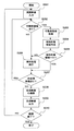
- FIG. 5 is a flowchart showing the processing contents in the first embodiment of the vehicle body external moving object detection system of the present invention
- FIG. 6 is the movable part region in the first embodiment of the vehicle body external moving object detection system of the present invention.
- FIG. 7 is a conceptual diagram showing an example of setting of a detection target area in the first embodiment of the vehicle body outside moving object detection system of the present invention
- FIG. 8A is a vehicle body external movement of the present invention.
- FIG. 8B is a conceptual diagram showing an image at a certain time as an example of detection of a moving object in the first embodiment of the object detection system
- FIG. 8B is a movement in the first embodiment of the vehicle body external moving object detection system of the present invention.
- FIG. 8C is a conceptual diagram illustrating an image at another time after a certain time as an example of object detection, and FIG. 8C is a moving object in the first embodiment of the vehicle body externally moving object detection system of the present invention.
- FIG. 9 is a conceptual diagram showing an example of the detection of a moving object in the first embodiment of the vehicle body external moving object detection system of the present invention, FIG. These are the conceptual diagrams which show the other example of the display result of the moving object detection in 1st Embodiment of the vehicle body external moving object detection system of this invention. 5 to FIG. 10, the same reference numerals as those shown in FIG. 1 to FIG. 4 are the same parts, and detailed description thereof is omitted.
- the vehicle body outside moving object detection device 100 performs ambient image input (step S201). Specifically, ambient images 401 to 404 photographed by the ambient image input unit 101 are input.
- the vehicle body outside moving object detection device 100 determines whether or not a movable part area is set in the movable part area setting unit 103 (step S202).
- region means the area
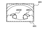
- FIG. 6 shows an example of setting of the movable area in the rear image 403.
- the left rear wheel 4B (L) and the right rear wheel 4B (R) are movable parts that rotate along the axle when the host vehicle 1 moves.
- a tire groove moves in the image.
- a region surrounding these portions in the video is set as a movable portion region 501 for the rear wheel 4B.
- the vehicle body outside moving object detection device 100 proceeds to (Step S203) when it is determined that such a movable part region is set, and proceeds to (Step S206) otherwise. .
- the vehicle body outside moving object detection device 100 acquires the movable part region (step S203). Specifically, the movable region setting unit 103 acquires information on the shape and arrangement of the movable region in the video. Here, by calculating which part of the host vehicle 1 is reflected in the rear camera 303 from the camera attribute information held by the movable region setting unit 103 such as the installation position and installation direction of the rear camera 303, FIG. As a result, the rear part of the host vehicle 1 and a part of the rear wheel 4B are reflected downward in the video. Further, using the information that the rear wheel 4B is a movable part, an area where the rear wheel 4B is reflected in the video is acquired as a movable part area 501. Further details will be described later.
- the vehicle body outside moving object detection device 100 creates a detection target area (step S204). Specifically, an area (detection target area) for detecting whether a moving object exists in the video is created.
- a detection target area for detecting whether a moving object exists in the video is created.
- all regions except the movable portion region 501 for the rear wheel 4B are created as detection targets, and this region is set as a rear detection target region 601.
- the vehicle body outside moving object detection device 100 determines whether or not the detection target area is the empty set ⁇ (step S205). Specifically, when the detection target area is created in (Step S204), for example, if the movable part area of the host vehicle 1 exists over the entire surface of the video, the detection target area is determined to be an empty set ⁇ . . Therefore, in the example shown in FIG. 7, since the movable part region 501 exists only in a part of the rear video 403, not the entire rear video 403, the empty set ⁇ is not determined. If it is determined that the detection target area is the empty set ⁇ , the process proceeds to (Step S207). Otherwise, the process proceeds to (Step S206).
- the vehicle body outside moving object detection device 100 performs the moving object detection process in the moving object detection unit 104 (step S206).
- the area in the video for which this detection process is performed is the detection target area created in step S204.
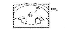
- FIGS. 8A to 8C show moving object detection processing in the rear video image 4003.
- FIG. 8A is a video image at a certain time t 0 -1 in order from the top
- FIG. 8B is a video image after a certain time t 0 ⁇ 1.
- FIG. 8C shows a detection result image. It is inside the detection target area 601 that performs the detection process in these images. In these videos, a person is present as a moving object.
- FIG. 8A shows a state in which the moving object 701 at a certain time t 0 ⁇ 1 is captured on the rear image 403, and FIG. 8B shows another time t 0 later than that.
- a state in which the moving object 702 is photographed on the rear image 403 is shown.
- the moving object detection unit 104 shown in FIG. 4 compares these images input from the surrounding image input unit 101, and calculates a location where the image has changed with the passage of time.
- the detection result 703 in the detection target area 601 obtained by the calculation holds coordinate information on the rear video 403. It should be noted that such a detection result cannot be obtained when there is no change in the image.
- the vehicle body outside moving object detection device 100 determines whether or not there is an unprocessed image (step S207). Specifically, it is determined whether or not a video to which the detection process is not applied remains in surrounding videos from a plurality of cameras. For example, in the present embodiment, a total of four detection processes are performed per frame for images taken by the front camera 301, the left camera 302, the rear camera 303, and the right camera 304 while switching the target video. Do.
- the vehicle body outside moving object detection device 100 proceeds to (Step S202) when determining that there is an unprocessed image, and proceeds to (Step S208) otherwise.
- the vehicle body outside moving object detection apparatus 100 constructs a composite image in the composite image construction unit 102 (step S208). Specifically, the front video 401, the left video 402, the rear video 403, and the right video 404 are reduced in area by halving the vertical and horizontal lengths, and these four types of video are adjacent to each other in a tile shape. By arranging them, images in four directions are displayed on one screen.
- FIG. 9 shows an example of the result display of such moving object detection.
- a tiled composite video 801 constructed by the composite video construction unit 102 is shown.
- the detection result 703 in the detection target area is drawn on the part where the moving object is detected.
- the vehicle body outside moving object detection device 100 outputs a composite image (step S209). Specifically, the tiled composite video 801 constructed by the composite video construction unit 102 is output to the output unit 105. In this video, the detection result 703 in the detection target area is displayed.
- the vehicle body outside moving object detection device 100 determines whether or not the detection process is completed (step S210). For example, when the work is completed or the detection of the external moving body is not required and a signal for instructing the process is input, the process ends. Otherwise, the process returns to the first procedure (step S201).
- the composite video construction unit 102 converts and synthesizes the images of the front video 401, the left video 402, the rear video 403, and the right video 404, and constructs a video that gives an overview of the host vehicle 1 and its surroundings, and outputs it. It is also possible to output to 103.
- Another example of the display of the result of such moving object detection is shown in FIG.
- the converted front image 901, the converted left image 902, the converted rear image 903, and the converted right image 904 are arranged in the upward direction, the left direction, the downward direction, and the right direction, respectively, and the own vehicle icon 905 is arranged in the center.
- the overhead view synthesized video 906 thus synthesized is synthesized. In this video, the detection result 703 in the detection target area is displayed.
- FIG. 11 is a block diagram showing the configuration of the movable part region setting unit in the first embodiment of the vehicle body external moving object detection system of the present invention
- FIG. 12 shows the first embodiment of the vehicle body external moving object detection system of the present invention
- FIG. 13 is a table showing an example of character data held in the host vehicle shape attribute holding unit in the embodiment
- FIG. 13 shows the processing content of the movable part region acquisition step in the first embodiment of the vehicle body external moving object detection system of the present invention.
- FIG. 14 is a conceptual diagram showing an example of calculation of the movable part region in the first embodiment of the vehicle body external moving object detection system of the present invention.
- FIG. 11 to FIG. 14 the same reference numerals as those shown in FIG. 1 to FIG.
- the movable part region setting unit 103 includes a host vehicle shape attribute holding unit 103A, a coordinate conversion unit 103B, and a movable part region detection unit 103C.
- the own vehicle shape attribute holding unit 103A holds shape information, attribute information, information on the movable part, and camera attribute information in each part constituting the own vehicle 1 shown in FIG. 2, and sends these to the coordinate conversion unit 103B.
- the shape information of the host vehicle 1 represents the spatial configuration of the host vehicle 1 by points, lines, and planes in a three-dimensional space, and is, for example, shape data for CAD. .
- the camera attribute information includes, for example, information attached to the camera such as the spatial installation position and direction of the front camera 301, the angle of view, and the focal length as front camera information.
- left camera information of the left camera 302, rear camera information of the rear camera 303, right camera information of the right camera 304, and the like are configured.
- the movable part of the host vehicle 1 refers to a part belonging to the host vehicle 1 that moves and rotates by a user's operation.
- the shape and arrangement of the left front wheel 4A (L) shown in FIG. 2 as the left front wheel information how the shape and arrangement on the image change depending on the operation of the host vehicle 1 such as steering and running, etc.
- FIG. 12 is a table showing an example of character data held in the own vehicle shape attribute holding unit 103A.
- the host vehicle 1 is indicated by a set of shape information and attribute information of each part.
- FIG. 12 illustrates a description of left front wheel information that is information related to the left front wheel 4A (L) and front camera information that is attribute information related to the front camera 301.
- the left front wheel information first describes that the attribute (Attribute) of the left front wheel 4A (L) is a movable part as attribute information.
- the shape (Shape) of the left front wheel 4A (L) is described as shape data for CAD as shape information.
- a position (Pivot), a movable range (Range), an angle (Angle), and the like as the center of movement and rotation of the left front wheel 4A (L), which is the movable part are also described.
- the front camera information describes the installation position (Position) of the front camera 301, the direction of the center (Direction), the angle of view (FOV), and the like.
- the shape of the own vehicle 1 is expressed by combining the information of each part which comprises the own vehicle 1.
- FIG. since processing is performed only for objects that may be reflected in each camera, information about shapes that are not likely to move in, for example, the roof of the own vehicle 1, etc. It is not necessary to hold in the holding unit 103A.
- the movable part region acquisition step is a more detailed description of the processing content of (step S203) in the processing flowchart shown in FIG.
- Step S202 If it is determined in (Step S202) in FIG. 5 that the movable part area has been set, the vehicle body outside moving object detection device 100 obtains the vehicle shape shown in FIG. 13 in order to obtain the movable part area. (Step S2031). Specifically, information on the shape of the host vehicle 1 held by the host vehicle shape attribute holding unit 103A is acquired.
- the vehicle body outside moving object detection device 100 acquires camera information (step S2032). Specifically, information about a camera that shoots video is acquired. For example, when shooting a video with the front camera 301, the front camera information is acquired.
- the vehicle body outside moving object detection device 100 executes coordinate conversion (step S2033).
- the coordinate conversion unit 103B shown in FIG. 11 performs coordinate conversion using the information on the shape of the host vehicle 1 acquired in the previous step and the attribute information of the camera, and represents an image captured by the camera. It is calculated how the three-dimensional shape is projected in the two-dimensional plane. This result is similar to the image captured by the camera shown in FIG. 3, and a part of the shape of the host vehicle 1 exists in an area on a two-dimensional plane.
- the vehicle body outside moving object detection device 100 calculates the movable part region (step S2034). Specifically, the movable part region detection unit 103C shown in FIG. 11 calculates the movable part region existing on the two-dimensional plane after the coordinate conversion.
- FIG. 14 shows coordinate conversion using shape information of the host vehicle 1 and rear camera information.
- shape information of the host vehicle 1 there are shapes representing a part of the rear portion of the vehicle body 2, the left rear wheel 4B (L), the right rear wheel 4B (R), and the vessel 3 among the shapes of the host vehicle. .
- the area occupied by the shape set as the movable part as an attribute is calculated.
- left rear wheel information H37, right rear wheel information H38, and vessel information H3 are movable as attribute information.
- the movable part region detection unit 103C shown in FIG. 11 calculates the region occupied by these on the two-dimensional plane, that is, the movable part region 501 for the rear wheel 4B, from the left rear wheel information H37 and the right rear wheel information H38.
- the vehicle body outside moving object detection device 100 outputs the movable part region (step S2035). Specifically, the movable region calculated by the movable region detector 103C is output to the moving object detector 104 shown in FIG. In the present embodiment, the movable part region 501 for the rear wheel 4B is output. After executing this process, the process proceeds to (step S204) in the process flowchart shown in FIG.
- the moving object is detected in the area excluding the movable area of the movable structure of the host vehicle from the surrounding image.
- the user can acquire only the moving object detection result required for work. As a result, the operational efficiency of the entire work can be improved.
- FIG. 15 is a block diagram showing the configuration of the second embodiment of the vehicle body external moving object detection system of the present invention
- FIG. 16 shows the vehicle information input unit in the second embodiment of the vehicle body external moving object detection system of the present invention.
- FIG. 17 is a conceptual diagram showing the relationship between the steering angle and the image in the second embodiment of the vehicle body outside moving object detection system of the present invention
- FIG. 18 is a vehicle body outside moving object detection of the present invention. It is a conceptual diagram which shows the relationship between the steering angle in the 2nd Embodiment of a system, and the shape of a movable part area
- FIG. 15 to FIG. 18 the same reference numerals as those shown in FIG. 1 to FIG.
- the vehicle surrounding moving object detection system in the present embodiment has a configuration and an operation method that are substantially the same as those in the first embodiment.
- the movable part of the host vehicle 1 moves with time and the movable part area in the video increases or decreases, the movable part moves in an area excluding these movable part areas.
- the difference from the first embodiment is that an object can be detected.
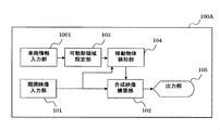
- the vehicle body outside moving object detection device 100 ⁇ / b> A further includes a vehicle information input unit 1001.
- the vehicle information input unit 1001 inputs information related to the movable part of the host vehicle 1. For example, information such as the steering angle of the host vehicle 1 and the operation amount of the vessel 3 is displayed as a CAN (Control Area Network). Input using etc.
- the vehicle information input unit 1001 calculates the shape of the movable part based on the input vehicle information, and outputs the vehicle information and the like to the movable part region setting unit 103 when the shape is included in the video.
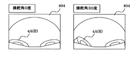
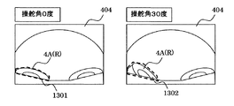
- the left side of FIG. 17 shows a right direction image 404 when the original steering angle is 0 degree.
- the right side of FIG. 17 shows a right direction image 404 when the user rotates the steering to the right by 30 degrees to set the steering angle to 30 degrees.
- the right front wheel 4A (R) rotates clockwise in the image to change the apparent shape.
- a steering angle of 0 degree is acquired from the vehicle information input unit 1001
- a steering angle of 30 degrees is acquired from the vehicle information input unit 1001.
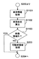
- the vehicle body outside moving object detection device 100A acquires vehicle information (step S1101). Specifically, information related to the vehicle is input from the vehicle information input unit 1001. For example, information on the steering angle as described above is input.
- the vehicle body outside moving object detection device 100A calculates the vehicle shape (step S1102). Specifically, the shape of the movable part of the vehicle 1 is calculated based on the input vehicle information. As described above, the arrangement of the right front wheel 4A (R) changes according to the magnitude of the steering angle. As shown in FIG. 17, when the steering angle is 30 degrees, the front portion of the right front wheel 4 ⁇ / b> A (R) protrudes to the right side corresponding to the outside of the vehicle body 2 as compared with the case where the steering angle is 0 degrees. Further, the rear portion of the right front wheel 4A (R) has a shape that enters the left side corresponding to the inside of the vehicle body 2.
- the vehicle body outside moving object detection device 100 determines whether or not it is outside the video area (step S ⁇ b> 1103). Specifically, it is determined whether or not the shape of the movable part of the host vehicle 1 calculated based on the input vehicle information is included in the target video. If the shape of the movable portion of the host vehicle 1 is outside the video area, the process proceeds to (Step S204), and otherwise, the process proceeds to (Step S203).
- the vehicle body outside moving object detection device 100A acquires the movable part region in the movable part region setting unit 103 (step S203). Specifically, the shape and arrangement in the video of the shape of the host vehicle 1 calculated based on the input vehicle information are acquired.
- the left side of FIG. 18 is a right direction image 404 when the steering angle is 0 degree, and the broken line portion indicates a movable region 1301 in the image.
- the right side of FIG. 18 is a right direction image 404 when the steering angle is 30 degrees, and the broken line portion indicates a movable region 1302 in the image.
- the vehicle-body-external moving object detection device 100A uses these movable part areas to detect a moving object in the same manner as in the first embodiment. As a result, even when the state of the host vehicle 1 changes, a movable part region corresponding to the state can be acquired, so that the movable part of the host vehicle 1 can be prevented from entering the detection target region. As a result, unnecessary false detection can be suppressed. Furthermore, since it is possible to avoid the area that should originally be included in the detection target area from being included in the movable portion area, it is possible to accurately detect a moving object. In particular, the necessary detection target area can be secured as wide as possible in the vicinity of the host vehicle 1 that is important for ensuring safety.
- the present invention is not limited to this.
- the case where the steering angle was used as the vehicle information to be input has been described as an example, the present invention is not limited to this.
- the operation amount of the vessel 3 can be input as vehicle information, and erroneous detection due to the movement of the vessel 3 in the video can be avoided.
- the movable part region is set accordingly, The necessary detection target area can be secured as wide as possible.
- FIG. 19 is a conceptual diagram showing an example of a result display of moving object detection in the third embodiment of the vehicle body external moving object detection system of the present invention.
- the same reference numerals as those shown in FIGS. 1 to 18 are the same parts, and detailed description thereof is omitted.
- the vehicle surrounding moving object detection system in the present embodiment has a configuration and an operation method that are substantially the same as those in the first embodiment.
- the third embodiment is different from the first embodiment in that the inside of the movable part region is not output to the output unit 105.
- the flow of processing in the present embodiment is the same as the processing shown in FIGS. However, since the processing content of (step S208) is different, this portion will be described.
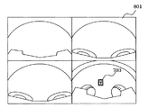
- a tiled composite video 801 as shown in FIG. 19 is constructed.
- the composite video constructing unit 102 of the vehicle body outside moving object detection device 100 shown in FIG. 4 performs a process of painting the inside of the movable part region 501 for the rear wheel 4B with a fixed color. In FIG. 19, it is uniformly painted white.
- the inside of the movable part region 501 that is not a detection target of the moving object is not displayed on the output unit 105.
- an unnecessary moving object can be hidden from the user's vision, and it is possible to avoid forcing the user to pay unnecessary attention to the unnecessary moving object.
- FIG. 20 is a conceptual diagram showing an example of a display result of moving object detection in the fourth embodiment of the vehicle body external moving object detection system of the present invention
- FIG. 21 is a fourth embodiment of the vehicle body external moving object detection system of the present invention. It is a conceptual diagram which shows the other example of a result display of the moving object detection in the form. 20 and FIG. 21, the same reference numerals as those shown in FIG. 1 to FIG. 19 are the same parts, and detailed description thereof will be omitted.
- the vehicle surrounding moving object detection system in the present embodiment has a configuration and an operation method that are substantially the same as those in the first embodiment.
- the fourth embodiment is different from the first embodiment in that the moving object detected in the movable part region is displayed by a method different from the display method of the moving object detected in other regions.
- the flow of processing in the present embodiment is the same as the processing shown in FIGS. However, since the processing content of (step S208) is different, this portion will be described.
- a tiled composite video 801 as shown in FIG. 20 is constructed.
- a graphic 1501 indicating that it is outside the detection target is enclosed so as to surround the movable part region 1302 when the steering angle is 30 degrees.
- an ellipse is drawn. This ellipse is drawn by a method different from the rectangle by the thick line in the detection result 703 in the detection target region. By doing so, an image of an object that is not an object of detection but is apparently moving is displayed in a manner different from the detection result 703 in the output unit 105.
- step S208 a case will be described in which composite video construction (step S208) is executed and an overhead view composite video 906 as shown in FIG. 21 is constructed.
- the composite image construction unit 102 of the vehicle body external moving object detection device 100A shown in FIG. 15 draws a graphic 1501 indicating that it is outside the detection target so as to surround the right front wheel when the steering angle is 30 degrees.
- an ellipse is drawn. This ellipse is drawn by a method different from the rectangle by the thick line in the detection result 703 in the detection target region. By doing so, an image of an object that is not an object of detection but is apparently moving is displayed in a manner different from the detection result 703 in the output unit 105.
- the fourth embodiment of the vehicle body external moving object detection system of the present invention described above, it is possible to indicate which of the moving objects in the image displayed on the output unit 105 is not the detection target. Because it can, it can avoid forcing unnecessary attention to the user.
- FIG. 22 is a block diagram showing the configuration of the fifth embodiment of the vehicle body external moving object detection system of the present invention
- FIG. 23 shows the moving object detection in the fifth embodiment of the vehicle body external moving object detection system of the present invention. It is a conceptual diagram which shows an example of a result display. 22 and FIG. 23, the same reference numerals as those shown in FIG. 1 to FIG.
- the vehicle surrounding moving object detection system in the present embodiment has a configuration and an operation method that are substantially the same as those in the first embodiment.
- the fifth embodiment differs from the first embodiment in that the user can change the arrangement of the movable part region in the video.
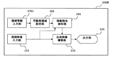
- the vehicle body outside moving object detection device 100B further includes an area information input unit 1701.
- the area information input unit 1701 includes an input device such as a keyboard, and the user can change the arrangement of the movable part area by designating coordinates in the video in the output unit. Is output to the movable part region setting unit 103. Note that the flow of processing in the present embodiment is the same as the processing shown in FIGS. However, since the processing content of acquisition of a movable part area
- step S203 The acquisition of the movable part region in the present embodiment (step S203) will be described with reference to FIG.
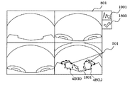
- an example of the tiled composite image 801 is shown.
- the position and angle of the front camera 301, the left camera 302, the rear camera 303, and the right camera 304 attached to the host vehicle 1 may not always meet specifications due to slight errors during installation. In such a case, there is a possibility that a shift occurs between the movable part area set by the movable part area setting unit 103 and the area actually occupied by the movable part in the video.
- the user inputs and designates the coordinates in the video in the output unit from the input device of the area information input unit 1701.
- the designated coordinates are indicated by an input cursor 1801.
- the setting completion button 1803 is pressed to complete the arrangement of the movable part region 501 with respect to the rear wheel 4B.
- the vehicle body outside moving object detection device 100B performs processing using the movable part region 501 for the newly arranged rear wheel 4B.
- the movable part region to be set there is a difference between the movable part region to be set and the region actually occupied by the movable part in the video. Even if it occurs, an accurate movable part region can be set again, so that the moving object detection process can be performed more accurately.
- FIG. 24 is a conceptual diagram showing an example of a result display of moving object detection in the sixth embodiment of the vehicle body external moving object detection system of the present invention. 24, the same reference numerals as those shown in FIG. 1 to FIG. 23 are the same parts, and the detailed description thereof is omitted.
- the vehicle surrounding moving object detection system in the present embodiment has a configuration and an operation method that are substantially the same as those in the fifth embodiment.
- the sixth embodiment is different from the fifth embodiment in that the user can draw the movable part region in the video.
- the front camera 301, the left camera 302, the rear camera 303, and the right camera 304 attached to the host vehicle 1 are positioned or If the angle does not necessarily meet the specifications, there is a possibility that a shift occurs between the movable part area set in the movable part area setting unit 103 and the area actually occupied by the movable part in the video.
- the user inputs and designates the coordinates in the video in the output unit from the input device of the area information input unit 1701.
- the designated coordinates are indicated by an input cursor 1801.
- Draw
- the setting completion button 1803 is pressed to complete the change of the shape of the movable part region 501 with respect to the rear wheel 4B.
- the vehicle body outside moving object detection device 100B performs processing using the movable part region 501 for the rear wheel 4B whose shape is newly changed.
- the embodiment of the present invention has been described by taking as an example a case where it is applied to a large dump truck as a construction machine, it is not limited to this. It can also be applied to large machines at construction sites and large work machines at disaster sites.
- this invention is not limited to the above-mentioned Example, Various modifications are included.
- the above-described embodiments have been described in detail for easy understanding of the present invention, and are not necessarily limited to those having all the configurations described.
- Each of the above-described configurations, functions, processing units, processing means, and the like may be realized by hardware by designing a part or all of them with, for example, an integrated circuit.
- Each of the above-described configurations, functions, and the like may be realized by software by interpreting and executing a program that realizes each function by the processor.
- 1 Dump truck (own vehicle), 2 body, 3 vessel (loading platform), 4A front wheel, 4B rear wheel, 8 cab, 100 body moving object detection device, 101 ambient video input unit, 102 composite video construction unit, 103 movable Area setting unit, 104, moving object detection unit, 105 output unit, 301 front camera, 302 left camera, 303 rear camera, 304 right camera, 401 front video, 402 left video, 403 rear video, 404 right video, 1001 Vehicle information input part, 1701 Area information input part, 1801 Input cursor.
Landscapes
- Engineering & Computer Science (AREA)
- Multimedia (AREA)
- Physics & Mathematics (AREA)
- General Physics & Mathematics (AREA)
- Theoretical Computer Science (AREA)
- Signal Processing (AREA)
- Civil Engineering (AREA)
- Mining & Mineral Resources (AREA)
- General Engineering & Computer Science (AREA)
- Structural Engineering (AREA)
- Computer Vision & Pattern Recognition (AREA)
- Mechanical Engineering (AREA)
- Human Computer Interaction (AREA)
- Closed-Circuit Television Systems (AREA)
- Image Analysis (AREA)
- Traffic Control Systems (AREA)
- Image Processing (AREA)
Abstract
Description
図1に示すダンプトラック(自車両)1は、頑丈なフレーム構造で形成された車体2と、車体2上に起伏可能に搭載されたベッセル(荷台)3と、車体2に装着された左前輪4A(L)及び左後輪4B(L)を主に備えている。
このように、自車両1を構成する各部分の情報を組合せることで、自車両1の形状を表現する。なお、本実施の形態においては、各カメラに映り込む可能性のある物体に関してのみ処理を行なうので、移りこむ可能性のない形状、例えば自車両1の屋根等についての情報は、自車両形状属性保持部103Aに保持しなくても良い。
車両情報入力部1001は、自車両1の可動部に関係する情報を入力するものであって、例えば、自車両1の操舵角度やベッセル3の作動量などの情報を、CAN(Control Area Network)等を用いて入力する。車両情報入力部1001は、入力した車両情報を基に可動部の形状を算出し、この形状が映像内に含まれる場合には、その車両情報等を可動部領域設定部103へ出力する。
Claims (5)
- 自車両の周囲の映像を撮影し周囲映像として送出する周囲映像入力部と、
移動物体検知の結果出力を含む合成映像を前記周囲映像から合成して構築する合成映像構築部と、
前記合成映像を利用者に提示する出力部とを備えた車体外部移動物体検知システムにおいて、
前記周囲映像における前記自車両の可動部の形状と配置を設定し、前記自車両の可動部の領域を算出する可動部領域設定部と、
前記可動部領域設定部が算出した可動部領域と前記周囲映像入力部から前記周囲映像を入力し、前記周囲映像から前記可動部領域を除いた領域に対して、移動物体の検知処理を行い検知の結果を出力する移動物体検知部とを備えた
ことを特徴とする車体外部移動物体検知システム。 - 請求項1に記載の車体外部移動物体検知システムにおいて、
前記自車両の情報を取得し送出する車両情報入力部を更に備え、
前記可動部領域設定部は、前記車両情報入力部からの前記自車両の情報を基に前記周囲映像内における前記可動部の形状と配置を算出する
ことを特徴とする車体外部移動物体検知システム。 - 請求項2に記載の車体外部移動物体検知システムにおいて、
前記合成映像構築部は、前記周囲映像内における前記可動部領域の表示を、前記移動物体の検知の結果表示とは異なる描画手法で行なう
ことを特徴とする車体外部移動物体検知システム。 - 請求項1または2に記載の車体外部移動物体検知システムにおいて、
前記出力部に表示している映像内における座標を入力可能な座標入力部を更に備え、
前記可動部領域設定部は、前記可動部領域を前記周囲映像内の前記座標入力部で入力した座標の位置へ移動させる
ことを特徴とする車体外部移動物体検知システム。 - 請求項1または2に記載の車体外部移動物体検知システムにおいて、
前記出力部に表示している映像内における領域を入力可能な領域入力部を更に備え、
前記可動部領域設定部は、前記周囲映像内の前記領域入力部で入力した領域を前記可動部領域として割り当てる
ことを特徴とする車体外部移動物体検知システム。
Priority Applications (2)
| Application Number | Priority Date | Filing Date | Title |
|---|---|---|---|
| CN201580045783.8A CN106797450B (zh) | 2015-02-04 | 2015-09-07 | 车身外部移动物体探测装置 |
| US15/511,301 US9990543B2 (en) | 2015-02-04 | 2015-09-07 | Vehicle exterior moving object detection system |
Applications Claiming Priority (2)
| Application Number | Priority Date | Filing Date | Title |
|---|---|---|---|
| JP2015019925A JP6456173B2 (ja) | 2015-02-04 | 2015-02-04 | 車体外部移動物体検知装置 |
| JP2015-019925 | 2015-02-04 |
Publications (1)
| Publication Number | Publication Date |
|---|---|
| WO2016125332A1 true WO2016125332A1 (ja) | 2016-08-11 |
Family
ID=56563691
Family Applications (1)
| Application Number | Title | Priority Date | Filing Date |
|---|---|---|---|
| PCT/JP2015/075361 Ceased WO2016125332A1 (ja) | 2015-02-04 | 2015-09-07 | 車体外部移動物体検知システム |
Country Status (4)
| Country | Link |
|---|---|
| US (1) | US9990543B2 (ja) |
| JP (1) | JP6456173B2 (ja) |
| CN (1) | CN106797450B (ja) |
| WO (1) | WO2016125332A1 (ja) |
Cited By (1)
| Publication number | Priority date | Publication date | Assignee | Title |
|---|---|---|---|---|
| JP2020165834A (ja) * | 2019-03-29 | 2020-10-08 | 日立建機株式会社 | 作業車両 |
Families Citing this family (20)
| Publication number | Priority date | Publication date | Assignee | Title |
|---|---|---|---|---|
| JP6664411B2 (ja) * | 2015-11-11 | 2020-03-13 | パイオニア株式会社 | セキュリティ装置、セキュリティ制御方法、プログラム及び記憶媒体 |
| EP3386195A4 (en) * | 2015-11-30 | 2018-12-19 | Sumitomo Heavy Industries, LTD. | Periphery monitoring system for work machine |
| JP6599835B2 (ja) * | 2016-09-23 | 2019-10-30 | 日立建機株式会社 | 鉱山用作業機械、障害物判別装置、及び障害物判別方法 |
| KR101949438B1 (ko) * | 2016-10-05 | 2019-02-19 | 엘지전자 주식회사 | 차량용 디스플레이 장치 및 이를 포함하는 차량 |
| KR101954199B1 (ko) * | 2016-12-09 | 2019-05-17 | 엘지전자 주식회사 | 차량용 어라운드 뷰 모니터링 장치, 운행 제어 장치 및 차량 |
| EP3587675B1 (en) * | 2017-02-22 | 2024-06-05 | Sumitomo (S.H.I.) Construction Machinery Co., Ltd. | Excavator |
| JP6926020B2 (ja) * | 2018-03-29 | 2021-08-25 | ヤンマーパワーテクノロジー株式会社 | 障害物検知システム |
| JP7091896B2 (ja) * | 2018-07-12 | 2022-06-28 | コベルコ建機株式会社 | 旋回式作業機械の安全装置 |
| JP7265323B2 (ja) * | 2018-07-31 | 2023-04-26 | 株式会社小松製作所 | 作業機械を制御するためのシステム及び方法 |
| EP3947088B1 (en) * | 2019-04-05 | 2024-03-13 | Volvo Truck Corporation | A method and a control unit for determining a parameter indicative of a road capability of a road segment supporting a vehicle |
| EP3960543A4 (en) * | 2019-04-26 | 2022-07-06 | Sumitomo Construction Machinery Co., Ltd. | DISPLAY DEVICE, SHOVEL, INFORMATION PROCESSING DEVICE |
| US10949685B2 (en) | 2019-07-22 | 2021-03-16 | Caterpillar Inc. | Excluding a component of a work machine from a video frame based on motion information |
| JP7419741B2 (ja) * | 2019-10-15 | 2024-01-23 | 株式会社アイシン | 駐車支援装置 |
| US11320830B2 (en) | 2019-10-28 | 2022-05-03 | Deere & Company | Probabilistic decision support for obstacle detection and classification in a working area |
| CN111340966B (zh) * | 2019-12-12 | 2022-03-08 | 山东中创软件工程股份有限公司 | 一种车辆检测方法、装置及系统 |
| KR102402254B1 (ko) * | 2020-01-20 | 2022-05-26 | 현대두산인프라코어 주식회사 | 휠 로더의 제어 시스템 및 방법 |
| JP7409240B2 (ja) * | 2020-07-02 | 2024-01-09 | 株式会社豊田自動織機 | 障害物検出装置及び障害物検出方法 |
| US12223549B2 (en) * | 2022-05-18 | 2025-02-11 | The Toronto-Dominion Bank | Systems and methods for automated data processing using machine learning for vehicle loss detection |
| US12227145B2 (en) * | 2023-01-20 | 2025-02-18 | Caterpillar Inc. | Machine security system |
| US20250044764A1 (en) * | 2023-08-01 | 2025-02-06 | Caterpillar Inc. | Nuisance condition detection system |
Citations (4)
| Publication number | Priority date | Publication date | Assignee | Title |
|---|---|---|---|---|
| JP2008248613A (ja) * | 2007-03-30 | 2008-10-16 | Hitachi Constr Mach Co Ltd | 作業機械周辺監視装置 |
| WO2012066589A1 (ja) * | 2010-11-15 | 2012-05-24 | 三菱電機株式会社 | 車載用画像処理装置 |
| JP2012160972A (ja) * | 2011-02-01 | 2012-08-23 | Canon Inc | 画像処理装置及び画像処理方法 |
| WO2014073571A1 (ja) * | 2012-11-08 | 2014-05-15 | 日立建機株式会社 | 自走式産業機械の画像処理装置および自走式産業機械の画像処理方法 |
Family Cites Families (6)
| Publication number | Priority date | Publication date | Assignee | Title |
|---|---|---|---|---|
| JP4809019B2 (ja) * | 2005-08-31 | 2011-11-02 | クラリオン株式会社 | 車両用障害物検出装置 |
| JP5272818B2 (ja) | 2009-03-13 | 2013-08-28 | オムロン株式会社 | 画像処理装置および方法、並びに、プログラム |
| US20150022664A1 (en) * | 2012-01-20 | 2015-01-22 | Magna Electronics Inc. | Vehicle vision system with positionable virtual viewpoint |
| KR101579100B1 (ko) * | 2014-06-10 | 2015-12-22 | 엘지전자 주식회사 | 차량용 어라운드뷰 제공 장치 및 이를 구비한 차량 |
| DE102015201317B4 (de) * | 2015-01-27 | 2025-03-20 | Bayerische Motoren Werke Aktiengesellschaft | Vermessen einer Abmessung auf einer Oberfläche |
| KR101942527B1 (ko) * | 2015-11-09 | 2019-01-25 | 엘지전자 주식회사 | 차량용 어라운드 뷰 제공 장치 및 차량 |
-
2015
- 2015-02-04 JP JP2015019925A patent/JP6456173B2/ja active Active
- 2015-09-07 US US15/511,301 patent/US9990543B2/en not_active Expired - Fee Related
- 2015-09-07 CN CN201580045783.8A patent/CN106797450B/zh not_active Expired - Fee Related
- 2015-09-07 WO PCT/JP2015/075361 patent/WO2016125332A1/ja not_active Ceased
Patent Citations (4)
| Publication number | Priority date | Publication date | Assignee | Title |
|---|---|---|---|---|
| JP2008248613A (ja) * | 2007-03-30 | 2008-10-16 | Hitachi Constr Mach Co Ltd | 作業機械周辺監視装置 |
| WO2012066589A1 (ja) * | 2010-11-15 | 2012-05-24 | 三菱電機株式会社 | 車載用画像処理装置 |
| JP2012160972A (ja) * | 2011-02-01 | 2012-08-23 | Canon Inc | 画像処理装置及び画像処理方法 |
| WO2014073571A1 (ja) * | 2012-11-08 | 2014-05-15 | 日立建機株式会社 | 自走式産業機械の画像処理装置および自走式産業機械の画像処理方法 |
Cited By (2)
| Publication number | Priority date | Publication date | Assignee | Title |
|---|---|---|---|---|
| JP2020165834A (ja) * | 2019-03-29 | 2020-10-08 | 日立建機株式会社 | 作業車両 |
| JP7374602B2 (ja) | 2019-03-29 | 2023-11-07 | 日立建機株式会社 | 作業車両 |
Also Published As
| Publication number | Publication date |
|---|---|
| JP6456173B2 (ja) | 2019-01-23 |
| CN106797450B (zh) | 2019-12-20 |
| US9990543B2 (en) | 2018-06-05 |
| JP2016144110A (ja) | 2016-08-08 |
| US20170286763A1 (en) | 2017-10-05 |
| CN106797450A (zh) | 2017-05-31 |
Similar Documents
| Publication | Publication Date | Title |
|---|---|---|
| JP6456173B2 (ja) | 車体外部移動物体検知装置 | |
| JP6262068B2 (ja) | 車体近傍障害物報知システム | |
| US12094151B2 (en) | Image processing system, image processing method, learned model generation method, and data set for learning | |
| US9167214B2 (en) | Image processing system using unified images | |
| US11427988B2 (en) | Display control device and display control method | |
| US20150098623A1 (en) | Image processing apparatus and method | |
| EP4050892B1 (en) | Work assist server, work assist method, and work assist system | |
| US10475154B2 (en) | Machine surround view system and method for generating 3-dimensional composite surround view using same | |
| AU2015234395A1 (en) | Real-time range map generation | |
| JP2009292254A (ja) | 車両操作システム及び車両操作方法 | |
| CN111767843B (zh) | 三维位置预测方法、装置、设备以及存储介质 | |
| JP6339337B2 (ja) | 車両周囲移動物体検知システム | |
| US20160301864A1 (en) | Imaging processing system for generating a surround-view image | |
| US12385230B2 (en) | Generation for earth-moving operations | |
| CN114521228A (zh) | 容器测量系统 | |
| US20160301863A1 (en) | Image processing system for generating a surround-view image | |
| CN112752068A (zh) | 作业车辆合成全景视觉系统 | |
| US12542875B2 (en) | Hybrid architecture of birds-eye view features and pixels for autonomous driving perception | |
| CN114821496A (zh) | 用于提供深度感知的视觉覆盖物 | |
| US20140293047A1 (en) | System for generating overhead view of machine | |
| US11472416B2 (en) | Multi-dimensional mobile machine path visualization and control system | |
| JP2016156629A (ja) | 外界認識装置、方法および車両 | |
| JP5968178B2 (ja) | 遠隔操縦用画像処理装置、遠隔操縦システム、及び遠隔操縦用画像処理方法 | |
| JP6796518B2 (ja) | 移動物体検知システム | |
| JP2024057361A (ja) | 作業支援装置および作業支援方法 |
Legal Events
| Date | Code | Title | Description |
|---|---|---|---|
| 121 | Ep: the epo has been informed by wipo that ep was designated in this application |
Ref document number: 15881149 Country of ref document: EP Kind code of ref document: A1 |
|
| WWE | Wipo information: entry into national phase |
Ref document number: 15511301 Country of ref document: US |
|
| NENP | Non-entry into the national phase |
Ref country code: DE |
|
| 32PN | Ep: public notification in the ep bulletin as address of the adressee cannot be established |
Free format text: NOTING OF LOSS OF RIGHTS PURSUANT TO RULE 112(1) EPC (EPO FORM 1205A DATED 06/11/2017) |
|
| 122 | Ep: pct application non-entry in european phase |
Ref document number: 15881149 Country of ref document: EP Kind code of ref document: A1 |