WO2016125328A1 - Switch gear - Google Patents
Switch gear Download PDFInfo
- Publication number
- WO2016125328A1 WO2016125328A1 PCT/JP2015/072496 JP2015072496W WO2016125328A1 WO 2016125328 A1 WO2016125328 A1 WO 2016125328A1 JP 2015072496 W JP2015072496 W JP 2015072496W WO 2016125328 A1 WO2016125328 A1 WO 2016125328A1
- Authority
- WO
- WIPO (PCT)
- Prior art keywords
- fixed
- movable
- side electrode
- electrode
- operation mechanism
- Prior art date
Links
Images


Classifications
-
- H—ELECTRICITY
- H01—ELECTRIC ELEMENTS
- H01H—ELECTRIC SWITCHES; RELAYS; SELECTORS; EMERGENCY PROTECTIVE DEVICES
- H01H33/00—High-tension or heavy-current switches with arc-extinguishing or arc-preventing means
- H01H33/02—Details
- H01H33/28—Power arrangements internal to the switch for operating the driving mechanism
- H01H33/38—Power arrangements internal to the switch for operating the driving mechanism using electromagnet
-
- H—ELECTRICITY
- H01—ELECTRIC ELEMENTS
- H01H—ELECTRIC SWITCHES; RELAYS; SELECTORS; EMERGENCY PROTECTIVE DEVICES
- H01H33/00—High-tension or heavy-current switches with arc-extinguishing or arc-preventing means
- H01H33/60—Switches wherein the means for extinguishing or preventing the arc do not include separate means for obtaining or increasing flow of arc-extinguishing fluid
- H01H33/66—Vacuum switches
- H01H33/662—Housings or protective screens
-
- H—ELECTRICITY
- H01—ELECTRIC ELEMENTS
- H01H—ELECTRIC SWITCHES; RELAYS; SELECTORS; EMERGENCY PROTECTIVE DEVICES
- H01H33/00—High-tension or heavy-current switches with arc-extinguishing or arc-preventing means
- H01H33/60—Switches wherein the means for extinguishing or preventing the arc do not include separate means for obtaining or increasing flow of arc-extinguishing fluid
- H01H33/66—Vacuum switches
- H01H33/666—Operating arrangements
Definitions
- the present invention relates to a switchgear that is used for power transmission / distribution, power distribution, etc., and opens and closes the power.
- a vacuum valve in which a movable electrode to be driven and at least one pair of fixed electrodes paired with the movable electrode are secretly sealed in a vacuum vessel divided into a plurality of vacuum chambers is provided in the switchgear housing. It is installed in. Further, the switch gear is configured to transmit the output of the operation mechanism installed in the switch gear housing to the movable electrode via the conversion shaft and the operation rod (for example, see Patent Document 1).
- the present invention has been made to solve the above-described problems.
- a switchgear that simplifies the connection structure between the movable electrode inside the vacuum vessel and the output shaft of the electromagnetic operation mechanism, and can prevent an increase in size. The purpose is to get.
- Another object of the present invention is to obtain a switchgear that can prevent a significant change when responding to various customer specifications.
- the switchgear according to the present invention is enclosed in a cylindrical vacuum vessel, and is provided at a fixed side electrode and a movable side electrode constituting a switch, and at an end of the vacuum vessel, and is fixed for current extraction.
- a fixed-side electrode rod connected to the side-connection conductor and connected to the fixed-side electrode; an electromagnetic operating mechanism that is arranged outside the vacuum vessel and has a linear drive shaft that linearly drives; and the movable-side electrode
- a movable electrode rod connected to the linear drive shaft of the electromagnetic operating mechanism via an insulating support rod disposed inside the vacuum vessel, and for extracting current from the movable electrode rod.
- the linear drive shaft and the central axis of each of the movable electrode rods are fixed in a state of being arranged on the same line, and the electromagnetic operation mechanism is an integrated single-phase module fixed to the mold insulator. It is characterized by.
- the switchgear since the drive direction of the electrode and the drive direction of the electromagnetic operation mechanism are all on the same line, connection with the conversion shaft and other modules is unnecessary and electromagnetic operation is performed in the main circuit connection direction. Since there is no mechanism, a switch gear having a compact configuration can be obtained.
- FIG. Embodiment 1 of the present invention will be described below with reference to the drawings.
- the switch gear 100 a includes a control box 1 that houses a control device for the first integrated single-phase module 50 a and the switch gear 100 a on the gantry 2.
- the first integrated single-phase module 50 a includes a cylindrical vacuum vessel 4 having an insulator, and a fixed side electrode 5 a and a movable side electrode 5 b that constitute a switch in the vacuum vessel 4.
- the first integrated single-phase module 50a is provided at the end of the vacuum vessel 4, and is connected to the fixed-side connection conductor 6 for extracting current and the fixed-side electrode rod 7 connected to the fixed-side electrode 5a. I have. Furthermore, the first integrated single-phase module 50a includes an electromagnetic operating mechanism 3 that is disposed outside the vacuum vessel 4 and has a linear drive shaft 8 that linearly drives.
- the first integrated single-phase module 50a is connected to the linear drive shaft 8 of the electromagnetic operating mechanism 3 through an insulating support rod 9 connected to the movable electrode 5b and disposed inside the vacuum vessel 4.
- the movable side electrode rod 10 is provided.
- the first integrated single-phase module 50 a has a flexible conductor 12 provided in the vacuum vessel 4 and connected to the movable side connection conductor 11 for taking out current from the movable side electrode rod 10.
- the insulating support rod 9 is disposed inside the vacuum vessel 4 for electrical insulation.
- the vacuum vessel 4, the fixed side connection conductor 6, and the movable side connection conductor 11 are covered with a mold insulator 14 that is a resin such as epoxy.
- the portion of the fixed side connection conductor 6 covered with the mold insulator 14 and the portion of the movable side connection conductor 11 covered with the mold insulator 14 are convex. It is molded into a shape.
- the cable connector 13 is connected in the up-down direction of the first integrated single-phase module 50a.
- the connection between the first integrated single-phase module 50a and another integrated single-phase module is performed by using a connection module in which a conductor is arranged at the center and the both ends are formed by another mold insulator having a concave shape.
- the mechanical drive unit has a configuration completed by the first integrated single-phase module 50a.
- the mechanical drive unit includes a movable side electrode 5 b, a linear drive shaft 8 of the electromagnetic operation mechanism 3, an insulating support bar 9, and a movable side electrode bar 10.
- FIG. 6 is a cross-sectional side view showing details of the electromagnetic operation mechanism 3 in the first embodiment. As shown in FIG.
- the electromagnetic operating mechanism 3 includes a movable iron core 21 that is integrally driven with the linear drive shaft 8 inside the fixed iron core 22, and is energized to the closing coil 9 or the opening coil 20.
- the linear drive shaft 8 and the movable iron core 21 operate.
- the mechanical drive units in the first integrated single-phase module 50a are all arranged on a straight line. As a result, it is not necessary to connect the drive unit with a conversion shaft in the drive direction or another module, and the electromagnetic operation mechanism 3 is not disposed in the main circuit connection direction.
- the switchgear 100a of the first embodiment of the present invention not only a compact configuration is possible, but also a simple structure without a conversion shaft in the driving direction is possible, and the reliability is excellent with excellent maintainability. It is possible to provide a high switchgear.
- the switch is a circuit breaker or a disconnector
- various switches can be modularized.
- the outer surface of the mold insulator 14 may be grounded with a conductive paint or resin. This not only reduces the risk of electric shock and increases safety, but also eliminates the need for a housing that covers the module, thereby reducing costs.
- the electromagnetic operating mechanism 3 changes the distance between the fixed side electrode 5a and the movable side electrode 5b in, for example, two stages, thereby changing the movable side electrode 5b between the cutoff position and the disconnector position, and opens and closes it.
- the switch can be a combined switchgear of a circuit breaker and a disconnect switch. As a result, the circuit breaker and the disconnecting device can be configured with the same electrode, and the number of parts and the number of necessary modules can be reduced when constructing the main circuit configuration necessary for the switchgear.
- FIG. FIG. 2 is a cross-sectional side view showing the main part of the switch gear according to Embodiment 2 of the present invention.
- the same reference numerals as those in the first embodiment are the same as those in the first embodiment, and the description thereof will be omitted.
- the second integrated single-phase module 50b includes a pair of electrodes 5 and a ground electrode 15 for opening and closing the ground.
- the electrode 5 is accommodated in a cylindrical first vacuum vessel 4a having an insulator.
- the ground electrode 15 is housed inside a cylindrical second vacuum vessel 4b having an insulator.
- the ground electrode 15 enclosed in the second vacuum vessel 4b includes a fixed side ground electrode 15a and a movable side ground electrode 15b.
- the second vacuum vessel 4b is connected to a fixed-side connection conductor 6 for taking out current sandwiched between the first vacuum vessel 4a and the second vacuum vessel 4b, and on the fixed side.
- a fixed-side ground electrode rod 16 connected to the ground electrode 15a is provided.
- the second integrated single-phase module 50b includes a second electromagnetic operation mechanism 3b having a second linear drive shaft 8b that is disposed outside the second vacuum vessel 4b and linearly drives. Further, the second electromagnetic operation mechanism 3b is disposed to face the first electromagnetic operation mechanism 3a. Furthermore, the second integrated single-layer module 50b includes a movable ground electrode bar 17 connected to the movable ground electrode 15b and coupled to the second linear drive shaft 8b of the second electromagnetic operation mechanism 3b. ing.
- the second linear drive shaft 8b and the movable-side ground electrode rod 17 are fixed in a state where their respective central axes are arranged on the same line.
- the first vacuum container 4a and the second vacuum container 4b, the fixed side connecting conductor 6 and the movable side connecting conductor 11 are covered with a mold insulator.
- the first electromagnetic operation mechanism 3 a and the second electromagnetic operation mechanism 3 b are fixed and attached to the mold insulator 14.
- the mechanical drive unit has a configuration completed by the second integrated single-phase module 50b.
- the switchgear of the second embodiment of the present invention even when the ground electrode 15 is combined with the electrode 5, one module in which all the mechanical drive units in the second integrated single-phase module 50b are in a straight line. Is possible. Further, there is no need to connect the conversion shaft in the drive direction and the drive unit with other modules, and the first electromagnetic operation mechanism 3a and the second electromagnetic operation mechanism 3b are not arranged in the main circuit connection direction.
- the second integrated single-phase module 50b is an independent structure whose structure is completed. Therefore, according to the switchgear of the second embodiment of the present invention, a compact configuration of the switchgear is possible even though the ground electrode is added to the configuration of the first embodiment.
- the switchgear of the second embodiment of the present invention a simple structure without a conversion shaft in the driving direction is possible, and it is possible to provide a highly reliable switchgear with good maintainability. Furthermore, the first electromagnetic operating mechanism 3a and the second electromagnetic operating mechanism 3b in the second embodiment of the present invention have the same configuration as the electromagnetic operating mechanism 3 in the first embodiment shown in FIG.
- FIG. 3 is an external view showing a switchgear according to Embodiment 3 of the present invention. More specifically, FIG. 3 is a front view when the single-phase module 50 is viewed from the cable connector 13 side.
- the same reference numerals as those in the first and second embodiments are the same as those in the first and second embodiments, and the description thereof will be omitted.
- three integrated single-phase modules 50 are arranged side by side in the horizontal direction to form a switch gear for three phases.
- FIG. 3 shows a configuration in which three single-phase modules 50 are arranged side by side and the cable connectors 13 are respectively connected from above and below.
- the integrated single-phase module 50 is an independent structure in which the structure is completed. For example, only one to four integrated single-phase modules 50 are arranged, and the single-phase module 50 corresponds to single-phase to four-phase.
- a switch can be constructed. According to the configuration of the switchgear according to the third embodiment of the present invention, it is easy to construct a switch corresponding to a single phase to a four phase, and standardization of each module makes it possible to shorten delivery times and reduce costs. .
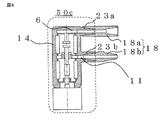
- FIG. 4 is a cross-sectional view showing a main part of a switchgear according to Embodiment 4 of the present invention.
- the same reference numerals as those in the first and second embodiments are the same as those in the first and second embodiments, and the description thereof will be omitted.
- the fixed-side connection conductor 6 is formed into a convex shape by a mold insulator 14 for main circuit connection with another module such as another integrated single-phase module. It has a portion 23a.
- the movable side connection conductor 11 has a concave molded portion 23b formed into a concave shape by a mold insulator.
- the molded portion 23a of the fixed-side connection conductor 6 of the mold insulator 14 has a convex shape
- the molded portion 23b of the movable-side connection conductor 11 of the mold insulator 14 has a concave shape. Or vice versa.
- the molded parts 23a and 23b of the mold insulator 14 are connected to a concave connection module 18a with respect to the convex shape and a convex connection module 18b with respect to the concave shape.
- the concave connection module 18a is a connection module in which a conductor is arranged at the center and is formed by another mold insulator having a concave shape at both ends.
- the convex connection module 18b is a connection module in which a conductor is arranged at the center, and both ends are formed by another mold insulator having a convex shape. According to such a configuration, it is possible to standardize the main circuit connection shape between the third integrated single-phase module 50c and another integrated single-phase module. According to the switchgear of the fourth embodiment of the present invention, connection with other modules becomes easy, and standardization of each module makes it possible to shorten delivery times and reduce costs.
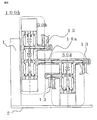
- FIG. 5 is a sectional view showing a switchgear according to Embodiment 5 of the present invention.
- the same reference numerals as those in the first and second embodiments are the same as those in the first and second embodiments, and the description thereof will be omitted.
- the second integrated single-phase module 50b and the fourth integrated single-phase module 50d are connected to each other by using a concave connection module 18a in the same phase. Is configured.
- a cable connector 13 is used for connection with other main circuit devices.
- the number of phases can be freely selected.
- the switchgear configuration of the fifth embodiment of the present invention it is easy to construct various main circuit configurations, and by standardizing each module, it is possible to shorten delivery time and cost. It should be noted that within the scope of the present invention, the embodiments can be freely combined, or the embodiments can be appropriately modified or omitted.
Landscapes
- Physics & Mathematics (AREA)
- Electromagnetism (AREA)
- High-Tension Arc-Extinguishing Switches Without Spraying Means (AREA)
- Gas-Insulated Switchgears (AREA)
Abstract
According to the present invention, a switch gear (100a) is obtained, which is a single body monophasic module comprising: a fixed-side electrode (5a) and a movable-side electrode (5b) constituting a switch, which are sealed inside a cylindrical vacuum container (4); a fixed-side electrode rod (7) provided at an extremity portion of the vacuum container (4), and connected to a fixed-side connection conductor (6) for current extraction while being connected to the fixed-side electrode (5a); an electromagnetic operation mechanism (3) disposed outside of the vacuum container (4) and having a linear drive axis (8); a movable-side electrode rod (10) coupled to the linear drive axis (8); and a movable-side connection conductor (11) covered, along with the vacuum container (4) and the fixed-side connection conductor (6), by a molded insulator (14). In this switch gear, the respective central axes of the fixed-side electrode (5a), the movable-side electrode (5b), the fixed-side electrode rod (7), the linear drive axis (8) of the electromagnetic operation mechanism (3), and the movable-side electrode rod (10) are fixed in a state in which the axes are disposed on the same line, and the electromagnetic operation mechanism (3) is fixed to the molded insulator (14).
Description
この発明は、電力の送配電および受配電などに用いられ、電力の開閉を行うスイッチギヤに関するものである。
The present invention relates to a switchgear that is used for power transmission / distribution, power distribution, etc., and opens and closes the power.
従来のスイッチギヤは、複数の真空室に分けられた真空容器内に、駆動される可動電極と、可動電極と対をなす固定電極が1対以上機密に封入された真空バルブをスイッチギヤ筺体内に設置している。また、スイッチギヤは、スイッチギヤ筺体内に設置した操作機構の出力を変換軸および操作ロッドを介して可動電極に伝達する構成となっている(例えば、特許文献1参照)。
In a conventional switchgear, a vacuum valve in which a movable electrode to be driven and at least one pair of fixed electrodes paired with the movable electrode are secretly sealed in a vacuum vessel divided into a plurality of vacuum chambers is provided in the switchgear housing. It is installed in. Further, the switch gear is configured to transmit the output of the operation mechanism installed in the switch gear housing to the movable electrode via the conversion shaft and the operation rod (for example, see Patent Document 1).
しかしながら、特許文献1に開示された従来のスイッチギヤは、各電極と操作機構出力軸が同軸上に配置されておらず、また、真空バルブおよび操作機構が、夫々独立してスイッチギヤ筺体に取り付けられている。そのため、真空バルブの可動電極と操作機構出力軸の接続構造が複雑化し、スイッチギヤの大型化を招くおそれがあった。
また、真空バルブおよび操作機構は、別ユニットとなっているため、様々な顧客仕様に応じて真空バルブおよび操作機構の配置方法、筺体構造、主回路導体の配置方法を大幅に変更しなければならないという問題点があった。 However, in the conventional switchgear disclosed inPatent Document 1, the electrodes and the operation mechanism output shaft are not coaxially arranged, and the vacuum valve and the operation mechanism are independently attached to the switchgear housing. It has been. For this reason, the connection structure between the movable electrode of the vacuum valve and the output shaft of the operation mechanism is complicated, which may increase the size of the switch gear.
In addition, since the vacuum valve and the operation mechanism are separate units, the arrangement method of the vacuum valve and operation mechanism, the housing structure, and the arrangement method of the main circuit conductor must be significantly changed according to various customer specifications. There was a problem.
また、真空バルブおよび操作機構は、別ユニットとなっているため、様々な顧客仕様に応じて真空バルブおよび操作機構の配置方法、筺体構造、主回路導体の配置方法を大幅に変更しなければならないという問題点があった。 However, in the conventional switchgear disclosed in
In addition, since the vacuum valve and the operation mechanism are separate units, the arrangement method of the vacuum valve and operation mechanism, the housing structure, and the arrangement method of the main circuit conductor must be significantly changed according to various customer specifications. There was a problem.
この発明は、前述のような課題を解決するためになされたもので、真空容器内部の可動側電極と電磁操作機構の出力軸の接続構造を簡略化し、大型化を防ぐことのできるスイッチギヤを得ることを目的としている。また、この発明は、様々な顧客仕様対応時の大幅な変更を防止することのできるスイッチギヤを得ることを目的としている。
The present invention has been made to solve the above-described problems. A switchgear that simplifies the connection structure between the movable electrode inside the vacuum vessel and the output shaft of the electromagnetic operation mechanism, and can prevent an increase in size. The purpose is to get. Another object of the present invention is to obtain a switchgear that can prevent a significant change when responding to various customer specifications.
この発明に係わるスイッチギヤは、筒状の真空容器の内部に封入されており、開閉器を構成する固定側電極および可動側電極と、前記真空容器の端部に設けられ、電流取り出し用の固定側接続導体に接続されると共に、前記固定側電極に接続される固定側電極棒と、前記真空容器の外部に配置され、直線駆動する直線駆動軸を有する電磁操作機構と、前記可動側電極に接続されると共に、前記真空容器の内部に配置された絶縁支持棒を介して前記電磁操作機構の前記直線駆動軸に連結される可動側電極棒と、前記可動側電極棒からの電流取り出し用であり、前記真空容器、前記固定側接続導体と共にモールド絶縁体によって被覆された可動側接続導体と、を備え、前記固定側電極、前記可動側電極、前記固定側電極棒、前記電磁操作機構の前記直線駆動軸および前記可動側電極棒のそれぞれの中心軸が同一線上に配置された状態で固定されており、前記電磁操作機構は、前記モールド絶縁体に固定された一体単相モジュールであることを特徴とするものである。
The switchgear according to the present invention is enclosed in a cylindrical vacuum vessel, and is provided at a fixed side electrode and a movable side electrode constituting a switch, and at an end of the vacuum vessel, and is fixed for current extraction. A fixed-side electrode rod connected to the side-connection conductor and connected to the fixed-side electrode; an electromagnetic operating mechanism that is arranged outside the vacuum vessel and has a linear drive shaft that linearly drives; and the movable-side electrode A movable electrode rod connected to the linear drive shaft of the electromagnetic operating mechanism via an insulating support rod disposed inside the vacuum vessel, and for extracting current from the movable electrode rod. A movable side connection conductor covered with a mold insulator together with the vacuum container, the fixed side electrode, the movable side electrode, the fixed side electrode rod, and the electromagnetic operating mechanism. The linear drive shaft and the central axis of each of the movable electrode rods are fixed in a state of being arranged on the same line, and the electromagnetic operation mechanism is an integrated single-phase module fixed to the mold insulator. It is characterized by.
この発明によるスイッチギヤによれば、電極の駆動方向、電磁操作機構の駆動方向が全て同一線上にあるため、変換軸や他のモジュールとの連結が不要であり、且つ主回路連結方向に電磁操作機構がないため、コンパクトな構成のスイッチギヤを得ることができる。
According to the switchgear according to the present invention, since the drive direction of the electrode and the drive direction of the electromagnetic operation mechanism are all on the same line, connection with the conversion shaft and other modules is unnecessary and electromagnetic operation is performed in the main circuit connection direction. Since there is no mechanism, a switch gear having a compact configuration can be obtained.
実施の形態1.
以下、図面に基づいてこの発明の実施の形態1について説明する。
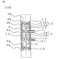
図1は、この発明の実施の形態1によるスイッチギヤを示す断面側面図である。図1に示すように、スイッチギヤ100aは、第1の一体単相モジュール50aおよびスイッチギヤ100aの制御装置を収納した制御箱1を架台2上に備えている。
第1の一体単相モジュール50aは、絶縁体を有する筒状の真空容器4と、この真空容器4内に開閉器を構成する固定側電極5aおよび可動側電極5bとを備えている。また、第1の一体単相モジュール50aは、真空容器4の端部に設けられ、電流取り出し用の固定側接続導体6に接続されると共に固定側電極5aに接続される固定側電極棒7を備えている。さらにまた、第1の一体単相モジュール50aは、真空容器4の外部に配置され、直線駆動する直線駆動軸8を有する電磁操作機構3を備えている。Embodiment 1 FIG.
Embodiment 1 of the present invention will be described below with reference to the drawings.
1 is a sectional side view showing a switchgear according toEmbodiment 1 of the present invention. As shown in FIG. 1, the switch gear 100 a includes a control box 1 that houses a control device for the first integrated single-phase module 50 a and the switch gear 100 a on the gantry 2.
The first integrated single-phase module 50 a includes acylindrical vacuum vessel 4 having an insulator, and a fixed side electrode 5 a and a movable side electrode 5 b that constitute a switch in the vacuum vessel 4. The first integrated single-phase module 50a is provided at the end of the vacuum vessel 4, and is connected to the fixed-side connection conductor 6 for extracting current and the fixed-side electrode rod 7 connected to the fixed-side electrode 5a. I have. Furthermore, the first integrated single-phase module 50a includes an electromagnetic operating mechanism 3 that is disposed outside the vacuum vessel 4 and has a linear drive shaft 8 that linearly drives.
以下、図面に基づいてこの発明の実施の形態1について説明する。
図1は、この発明の実施の形態1によるスイッチギヤを示す断面側面図である。図1に示すように、スイッチギヤ100aは、第1の一体単相モジュール50aおよびスイッチギヤ100aの制御装置を収納した制御箱1を架台2上に備えている。
第1の一体単相モジュール50aは、絶縁体を有する筒状の真空容器4と、この真空容器4内に開閉器を構成する固定側電極5aおよび可動側電極5bとを備えている。また、第1の一体単相モジュール50aは、真空容器4の端部に設けられ、電流取り出し用の固定側接続導体6に接続されると共に固定側電極5aに接続される固定側電極棒7を備えている。さらにまた、第1の一体単相モジュール50aは、真空容器4の外部に配置され、直線駆動する直線駆動軸8を有する電磁操作機構3を備えている。
1 is a sectional side view showing a switchgear according to
The first integrated single-phase module 50 a includes a
また、第1の一体単相モジュール50aは、可動側電極5bに接続されると共に真空容器4の内部に配置された絶縁支持棒9を介して、電磁操作機構3の直線駆動軸8に連結される可動側電極棒10を有している。さらにまた、第1の一体単相モジュール50aは、真空容器4に設けられ、可動側電極棒10からの電流取り出し用の可動側接続導体11に接続する可とう性導体12を有している。なお、絶縁支持棒9は、電気的絶縁を行うために真空容器4の内部に配置されている。
真空容器4、固定側接続導体6および可動側接続導体11は、エポキシ等の樹脂であるモールド絶縁体14によって被覆されている。
また、他の主回路機器との接続のため、固定側接続導体6のモールド絶縁体14で被覆されている部分および可動側接続導体11のモールド絶縁体14で被覆されている部分は、凸形形状に成形されている。図1においては、第1の一体単相モジュール50aの上下方向にケーブルコネクタ13が接続されている。第1の一体単相モジュール50aと別の一体単相モジュールとの接続は、中心に導体を配し両端が凹形状の別のモールド絶縁体によって成形された接続モジュールを用いておこなう。 The first integrated single-phase module 50a is connected to thelinear drive shaft 8 of the electromagnetic operating mechanism 3 through an insulating support rod 9 connected to the movable electrode 5b and disposed inside the vacuum vessel 4. The movable side electrode rod 10 is provided. Furthermore, the first integrated single-phase module 50 a has a flexible conductor 12 provided in the vacuum vessel 4 and connected to the movable side connection conductor 11 for taking out current from the movable side electrode rod 10. The insulating support rod 9 is disposed inside the vacuum vessel 4 for electrical insulation.
Thevacuum vessel 4, the fixed side connection conductor 6, and the movable side connection conductor 11 are covered with a mold insulator 14 that is a resin such as epoxy.
Further, for connection with other main circuit equipment, the portion of the fixedside connection conductor 6 covered with the mold insulator 14 and the portion of the movable side connection conductor 11 covered with the mold insulator 14 are convex. It is molded into a shape. In FIG. 1, the cable connector 13 is connected in the up-down direction of the first integrated single-phase module 50a. The connection between the first integrated single-phase module 50a and another integrated single-phase module is performed by using a connection module in which a conductor is arranged at the center and the both ends are formed by another mold insulator having a concave shape.
真空容器4、固定側接続導体6および可動側接続導体11は、エポキシ等の樹脂であるモールド絶縁体14によって被覆されている。
また、他の主回路機器との接続のため、固定側接続導体6のモールド絶縁体14で被覆されている部分および可動側接続導体11のモールド絶縁体14で被覆されている部分は、凸形形状に成形されている。図1においては、第1の一体単相モジュール50aの上下方向にケーブルコネクタ13が接続されている。第1の一体単相モジュール50aと別の一体単相モジュールとの接続は、中心に導体を配し両端が凹形状の別のモールド絶縁体によって成形された接続モジュールを用いておこなう。 The first integrated single-phase module 50a is connected to the
The
Further, for connection with other main circuit equipment, the portion of the fixed
さらに、固定側電極5a、可動側電極5b、固定側電極棒7、電磁操作機構3の直線駆動軸8および可動側電極棒10は、それぞれの中心軸が同一線上に配置された状態で固定されている。また、電磁操作機構3は、モールド絶縁体14に固定されて取り付けられている。実施の形態1において、機械的駆動部は、第1の一体単相モジュール50aにて完結した構成である。図1において、機械的駆動部は、可動側電極5b、電磁操作機構3の直線駆動軸8、絶縁支持棒9、可動側電極棒10で構成されている。
また、図6は、実施の形態1における電磁操作機構3の詳細を示す断面側面図である。図6に示すように、電磁操作機構3は、固定鉄心22の内部に、直線駆動軸8と一体駆動する可動鉄心21を備えており、閉極コイル9、あるいは開極コイル20への通電により、直線駆動軸8および可動鉄心21が動作を行う。
この発明の実施の形態1のスイッチギヤ100aによれば、第1の一体単相モジュール50a内の機械的駆動部が、全て一直線上に配置されている。その結果、駆動方向の変換軸や他のモジュールとの駆動部連結が不要となり、かつ主回路連結方向に電磁操作機構3を配置することがなくなる。
また、この発明の実施の形態1のスイッチギヤ100aによれば、コンパクトな構成が可能となるだけでなく、駆動方向の変換軸の無いシンプルな構造が可能となり、メンテナンス性に優れた信頼性の高いスイッチギヤの提供が可能となる。 Furthermore, the fixed side electrode 5a, themovable side electrode 5b, the fixed side electrode rod 7, the linear drive shaft 8 and the movable side electrode rod 10 of the electromagnetic operating mechanism 3 are fixed in a state in which the respective central axes are arranged on the same line. ing. The electromagnetic operation mechanism 3 is fixedly attached to the mold insulator 14. In the first embodiment, the mechanical drive unit has a configuration completed by the first integrated single-phase module 50a. In FIG. 1, the mechanical drive unit includes a movable side electrode 5 b, a linear drive shaft 8 of the electromagnetic operation mechanism 3, an insulating support bar 9, and a movable side electrode bar 10.
FIG. 6 is a cross-sectional side view showing details of theelectromagnetic operation mechanism 3 in the first embodiment. As shown in FIG. 6, the electromagnetic operating mechanism 3 includes a movable iron core 21 that is integrally driven with the linear drive shaft 8 inside the fixed iron core 22, and is energized to the closing coil 9 or the opening coil 20. The linear drive shaft 8 and the movable iron core 21 operate.
According to the switchgear 100a of the first embodiment of the present invention, the mechanical drive units in the first integrated single-phase module 50a are all arranged on a straight line. As a result, it is not necessary to connect the drive unit with a conversion shaft in the drive direction or another module, and theelectromagnetic operation mechanism 3 is not disposed in the main circuit connection direction.
Further, according to the switchgear 100a of the first embodiment of the present invention, not only a compact configuration is possible, but also a simple structure without a conversion shaft in the driving direction is possible, and the reliability is excellent with excellent maintainability. It is possible to provide a high switchgear.
また、図6は、実施の形態1における電磁操作機構3の詳細を示す断面側面図である。図6に示すように、電磁操作機構3は、固定鉄心22の内部に、直線駆動軸8と一体駆動する可動鉄心21を備えており、閉極コイル9、あるいは開極コイル20への通電により、直線駆動軸8および可動鉄心21が動作を行う。
この発明の実施の形態1のスイッチギヤ100aによれば、第1の一体単相モジュール50a内の機械的駆動部が、全て一直線上に配置されている。その結果、駆動方向の変換軸や他のモジュールとの駆動部連結が不要となり、かつ主回路連結方向に電磁操作機構3を配置することがなくなる。
また、この発明の実施の形態1のスイッチギヤ100aによれば、コンパクトな構成が可能となるだけでなく、駆動方向の変換軸の無いシンプルな構造が可能となり、メンテナンス性に優れた信頼性の高いスイッチギヤの提供が可能となる。 Furthermore, the fixed side electrode 5a, the
FIG. 6 is a cross-sectional side view showing details of the
According to the switchgear 100a of the first embodiment of the present invention, the mechanical drive units in the first integrated single-phase module 50a are all arranged on a straight line. As a result, it is not necessary to connect the drive unit with a conversion shaft in the drive direction or another module, and the
Further, according to the switchgear 100a of the first embodiment of the present invention, not only a compact configuration is possible, but also a simple structure without a conversion shaft in the driving direction is possible, and the reliability is excellent with excellent maintainability. It is possible to provide a high switchgear.
また、実施の形態1において、開閉器は、遮断器あるいは断路器であるので、様々な開閉器のモジュール化が可能となる。さらにまた、モールド絶縁体14の外側表面は、導電性の塗料あるいは樹脂により接地されていてもよい。これにより、感電のおそれが減少し、安全性が高くなるのみでなく、モジュールを覆う筺体が不要となり、コストの削減が可能となる。さらにまた、電磁操作機構3は、固定側電極5aと可動側電極5bとの間の距離を例えば2段階に変更させることにより、可動側電極5bを遮断位置と断路器位置とに変更させ、開閉器を遮断器と断路器の複合開閉装置とすることができる。これにより、遮断器と断路器を同一電極で構成することが可能となり、スイッチギヤに必要な主回路構成の構築時に、部品点数の削減と、必要モジュール数の削減が可能となる。
In Embodiment 1, since the switch is a circuit breaker or a disconnector, various switches can be modularized. Furthermore, the outer surface of the mold insulator 14 may be grounded with a conductive paint or resin. This not only reduces the risk of electric shock and increases safety, but also eliminates the need for a housing that covers the module, thereby reducing costs. Furthermore, the electromagnetic operating mechanism 3 changes the distance between the fixed side electrode 5a and the movable side electrode 5b in, for example, two stages, thereby changing the movable side electrode 5b between the cutoff position and the disconnector position, and opens and closes it. The switch can be a combined switchgear of a circuit breaker and a disconnect switch. As a result, the circuit breaker and the disconnecting device can be configured with the same electrode, and the number of parts and the number of necessary modules can be reduced when constructing the main circuit configuration necessary for the switchgear.
実施の形態2.
図2は、この発明の実施の形態2におけるスイッチギヤの要部を示す断面側面図である。実施の形態2において、実施の形態1と同一の符号については、実施の形態1と同一の構成であるので説明を省略する。図2に示すように、第2の一体単相モジュール50bの内部には、1組の電極5を収納すると共に、接地開閉を目的とした接地電極15を備えている。電極5は、絶縁体を有する筒状の第1の真空容器4aの内部に収納されている。また、接地電極15は、絶縁体を有する筒状の第2の真空容器4bの内部に収納されている。
第2の真空容器4bの内部に封入された接地電極15は、固定側接地電極15aおよび可動側接地電極15bを備えている。また、第2の真空容器4bの内部には、第1の真空容器4aと第2の真空容器4bとの間に挟まれた電流取り出し用の固定側接続導体6に接続されると共に、固定側接地電極15aに接続される固定側接地電極棒16が設けられている。Embodiment 2. FIG.
FIG. 2 is a cross-sectional side view showing the main part of the switch gear according toEmbodiment 2 of the present invention. In the second embodiment, the same reference numerals as those in the first embodiment are the same as those in the first embodiment, and the description thereof will be omitted. As shown in FIG. 2, the second integrated single-phase module 50b includes a pair of electrodes 5 and a ground electrode 15 for opening and closing the ground. The electrode 5 is accommodated in a cylindrical first vacuum vessel 4a having an insulator. The ground electrode 15 is housed inside a cylindrical second vacuum vessel 4b having an insulator.
The ground electrode 15 enclosed in the second vacuum vessel 4b includes a fixed side ground electrode 15a and a movable side ground electrode 15b. In addition, the second vacuum vessel 4b is connected to a fixed-side connection conductor 6 for taking out current sandwiched between the first vacuum vessel 4a and the second vacuum vessel 4b, and on the fixed side. A fixed-side ground electrode rod 16 connected to the ground electrode 15a is provided.
図2は、この発明の実施の形態2におけるスイッチギヤの要部を示す断面側面図である。実施の形態2において、実施の形態1と同一の符号については、実施の形態1と同一の構成であるので説明を省略する。図2に示すように、第2の一体単相モジュール50bの内部には、1組の電極5を収納すると共に、接地開閉を目的とした接地電極15を備えている。電極5は、絶縁体を有する筒状の第1の真空容器4aの内部に収納されている。また、接地電極15は、絶縁体を有する筒状の第2の真空容器4bの内部に収納されている。
第2の真空容器4bの内部に封入された接地電極15は、固定側接地電極15aおよび可動側接地電極15bを備えている。また、第2の真空容器4bの内部には、第1の真空容器4aと第2の真空容器4bとの間に挟まれた電流取り出し用の固定側接続導体6に接続されると共に、固定側接地電極15aに接続される固定側接地電極棒16が設けられている。
FIG. 2 is a cross-sectional side view showing the main part of the switch gear according to
The ground electrode 15 enclosed in the second vacuum vessel 4b includes a fixed side ground electrode 15a and a movable side ground electrode 15b. In addition, the second vacuum vessel 4b is connected to a fixed-
さらにまた、第2の一体単相モジュール50bは、第2の真空容器4bの外部に配置され、直線駆動する第2の直線駆動軸8bを有する第2の電磁操作機構3bを備えている。また、第2の電磁操作機構3bは、第1の電磁操作機構3aに対向して配置されている。さらにまた、第2の一体単層モジュール50bは、可動側接地電極15bに接続されると共に、第2の電磁操作機構3bの第2の直線駆動軸8bに連結する可動側接地電極棒17を備えている。
さらに、固定側電極5a、可動側電極5b、固定側電極棒7、第1の直線駆動軸8a、可動側電極棒10、固定側接地電極15a、可動側接地電極15b、固定側接地電極棒16、第2の直線駆動軸8bおよび可動側接地電極棒17は、それぞれの中心軸が同一線上に配置された状態で固定されている。また、第1の真空容器4aおよび第2の真空容器4b、固定側接続導体6および可動側接続導体11は、モールド絶縁体によって被覆されている。第1の電磁操作機構3aおよび第2の電磁操作機構3bは、モールド絶縁体14に固定され取り付けられている。また、機械的駆動部は、第2の一体単相モジュール50bにて完結した構成である。 Furthermore, the second integrated single-phase module 50b includes a second electromagnetic operation mechanism 3b having a secondlinear drive shaft 8b that is disposed outside the second vacuum vessel 4b and linearly drives. Further, the second electromagnetic operation mechanism 3b is disposed to face the first electromagnetic operation mechanism 3a. Furthermore, the second integrated single-layer module 50b includes a movable ground electrode bar 17 connected to the movable ground electrode 15b and coupled to the second linear drive shaft 8b of the second electromagnetic operation mechanism 3b. ing.
Furthermore, the fixed side electrode 5a, themovable side electrode 5b, the fixed side electrode rod 7, the first linear drive shaft 8a, the movable side electrode rod 10, the fixed side ground electrode 15a, the movable side ground electrode 15b, and the fixed side ground electrode rod 16 The second linear drive shaft 8b and the movable-side ground electrode rod 17 are fixed in a state where their respective central axes are arranged on the same line. The first vacuum container 4a and the second vacuum container 4b, the fixed side connecting conductor 6 and the movable side connecting conductor 11 are covered with a mold insulator. The first electromagnetic operation mechanism 3 a and the second electromagnetic operation mechanism 3 b are fixed and attached to the mold insulator 14. Further, the mechanical drive unit has a configuration completed by the second integrated single-phase module 50b.
さらに、固定側電極5a、可動側電極5b、固定側電極棒7、第1の直線駆動軸8a、可動側電極棒10、固定側接地電極15a、可動側接地電極15b、固定側接地電極棒16、第2の直線駆動軸8bおよび可動側接地電極棒17は、それぞれの中心軸が同一線上に配置された状態で固定されている。また、第1の真空容器4aおよび第2の真空容器4b、固定側接続導体6および可動側接続導体11は、モールド絶縁体によって被覆されている。第1の電磁操作機構3aおよび第2の電磁操作機構3bは、モールド絶縁体14に固定され取り付けられている。また、機械的駆動部は、第2の一体単相モジュール50bにて完結した構成である。 Furthermore, the second integrated single-phase module 50b includes a second electromagnetic operation mechanism 3b having a second
Furthermore, the fixed side electrode 5a, the
この発明の実施の形態2のスイッチギヤによれば、電極5に接地電極15が複合された場合でも、第2の一体単相モジュール50b内の機械的駆動部が全て一直線上となる1つのモジュールの構成が可能である。また、駆動方向の変換軸や他のモジュールとの駆動部連結が不要となり、且つ主回路連結方向に第1の電磁操作機構3a、第2の電磁操作機構3bを配置することがなくなる。また、第2の一体単相モジュール50bは、その構造が完結した独立構造である。よって、この発明の実施の形態2のスイッチギヤによれば、実施の形態1の構成に接地電極が追加されたにもかかわらず、スイッチギヤのコンパクトな構成が可能となる。また、この発明の実施の形態2のスイッチギヤによれば、駆動方向の変換軸の無いシンプルな構造が可能となり、メンテナンス性の良い信頼性の高いスイッチギヤの提供が可能となる。さらに、この発明の実施の形態2における第1の電磁操作機構3aおよび第2の電磁操作機構3bは、図6に示した実施の形態1における電磁操作機構3と同様の構成を備えている。
According to the switchgear of the second embodiment of the present invention, even when the ground electrode 15 is combined with the electrode 5, one module in which all the mechanical drive units in the second integrated single-phase module 50b are in a straight line. Is possible. Further, there is no need to connect the conversion shaft in the drive direction and the drive unit with other modules, and the first electromagnetic operation mechanism 3a and the second electromagnetic operation mechanism 3b are not arranged in the main circuit connection direction. The second integrated single-phase module 50b is an independent structure whose structure is completed. Therefore, according to the switchgear of the second embodiment of the present invention, a compact configuration of the switchgear is possible even though the ground electrode is added to the configuration of the first embodiment. Further, according to the switchgear of the second embodiment of the present invention, a simple structure without a conversion shaft in the driving direction is possible, and it is possible to provide a highly reliable switchgear with good maintainability. Furthermore, the first electromagnetic operating mechanism 3a and the second electromagnetic operating mechanism 3b in the second embodiment of the present invention have the same configuration as the electromagnetic operating mechanism 3 in the first embodiment shown in FIG.
実施の形態3.
図3は、この発明の実施の形態3におけるスイッチギヤを示す外形図である。より詳細には、図3は、ケーブルコネクタ13側から一体単相モジュール50を見た時の正面図である。実施の形態3において、実施の形態1および実施の形態2と同一の符号については、実施の形態1および実施の形態2と同一の構成であるので説明を省略する。図3においては、一体単相モジュール50が横方向に3台並んで配置されており、3相用のスイッチギヤとなっている。図3は、一体単相モジュール50を3台並べ、上下方向から夫々ケーブルコネクタ13を接続した構成となっている。
このような構成によれば、一体単相モジュール50は、構造が完結した独立構造であるため、例えば、一体単相モジュール50を1台から4台並べるのみで、単相から4相に対応した開閉器の構築が可能である。
この発明の実施の形態3のスイッチギヤの構成によれば、単相から4相に対応した開閉器の構築が容易であり、各モジュールの標準化により、納期の短縮、コストの削減が可能となる。Embodiment 3 FIG.
FIG. 3 is an external view showing a switchgear according toEmbodiment 3 of the present invention. More specifically, FIG. 3 is a front view when the single-phase module 50 is viewed from the cable connector 13 side. In the third embodiment, the same reference numerals as those in the first and second embodiments are the same as those in the first and second embodiments, and the description thereof will be omitted. In FIG. 3, three integrated single-phase modules 50 are arranged side by side in the horizontal direction to form a switch gear for three phases. FIG. 3 shows a configuration in which three single-phase modules 50 are arranged side by side and the cable connectors 13 are respectively connected from above and below.
According to such a configuration, the integrated single-phase module 50 is an independent structure in which the structure is completed. For example, only one to four integrated single-phase modules 50 are arranged, and the single-phase module 50 corresponds to single-phase to four-phase. A switch can be constructed.
According to the configuration of the switchgear according to the third embodiment of the present invention, it is easy to construct a switch corresponding to a single phase to a four phase, and standardization of each module makes it possible to shorten delivery times and reduce costs. .
図3は、この発明の実施の形態3におけるスイッチギヤを示す外形図である。より詳細には、図3は、ケーブルコネクタ13側から一体単相モジュール50を見た時の正面図である。実施の形態3において、実施の形態1および実施の形態2と同一の符号については、実施の形態1および実施の形態2と同一の構成であるので説明を省略する。図3においては、一体単相モジュール50が横方向に3台並んで配置されており、3相用のスイッチギヤとなっている。図3は、一体単相モジュール50を3台並べ、上下方向から夫々ケーブルコネクタ13を接続した構成となっている。
このような構成によれば、一体単相モジュール50は、構造が完結した独立構造であるため、例えば、一体単相モジュール50を1台から4台並べるのみで、単相から4相に対応した開閉器の構築が可能である。
この発明の実施の形態3のスイッチギヤの構成によれば、単相から4相に対応した開閉器の構築が容易であり、各モジュールの標準化により、納期の短縮、コストの削減が可能となる。
FIG. 3 is an external view showing a switchgear according to
According to such a configuration, the integrated single-
According to the configuration of the switchgear according to the third embodiment of the present invention, it is easy to construct a switch corresponding to a single phase to a four phase, and standardization of each module makes it possible to shorten delivery times and reduce costs. .
実施の形態4.
図4は、この発明の実施の形態4におけるスイッチギヤの要部を示す断面図である。実施の形態4においては、実施の形態1および実施の形態2と同一の符号については、実施の形態1および実施の形態2と同一の構成であるので説明を省略する。
図4に示すように、例えば別の一体単相モジュールなどの他のモジュールとの主回路接続のため、固定側接続導体6は、モールド絶縁体14により凸形状に成形された凸形状のモールド成形部分23aを有している。また、可動側接続導体11は、モールド絶縁体により凹形状に成形された凹形状のモールド成形部分23bを有している。なお、実施の形態4においては、モールド絶縁体14の固定側接続導体6のモールド成形部分23aを凸形状とし、モールド絶縁体14の可動側接続導体11のモールド成形部分23bを凹形状としたが、その逆を選択しても良い。Embodiment 4 FIG.
4 is a cross-sectional view showing a main part of a switchgear according toEmbodiment 4 of the present invention. In the fourth embodiment, the same reference numerals as those in the first and second embodiments are the same as those in the first and second embodiments, and the description thereof will be omitted.
As shown in FIG. 4, for example, the fixed-side connection conductor 6 is formed into a convex shape by a mold insulator 14 for main circuit connection with another module such as another integrated single-phase module. It has a portion 23a. In addition, the movable side connection conductor 11 has a concave molded portion 23b formed into a concave shape by a mold insulator. In the fourth embodiment, the molded portion 23a of the fixed-side connection conductor 6 of the mold insulator 14 has a convex shape, and the molded portion 23b of the movable-side connection conductor 11 of the mold insulator 14 has a concave shape. Or vice versa.
図4は、この発明の実施の形態4におけるスイッチギヤの要部を示す断面図である。実施の形態4においては、実施の形態1および実施の形態2と同一の符号については、実施の形態1および実施の形態2と同一の構成であるので説明を省略する。
図4に示すように、例えば別の一体単相モジュールなどの他のモジュールとの主回路接続のため、固定側接続導体6は、モールド絶縁体14により凸形状に成形された凸形状のモールド成形部分23aを有している。また、可動側接続導体11は、モールド絶縁体により凹形状に成形された凹形状のモールド成形部分23bを有している。なお、実施の形態4においては、モールド絶縁体14の固定側接続導体6のモールド成形部分23aを凸形状とし、モールド絶縁体14の可動側接続導体11のモールド成形部分23bを凹形状としたが、その逆を選択しても良い。
4 is a cross-sectional view showing a main part of a switchgear according to
As shown in FIG. 4, for example, the fixed-
これらモールド絶縁体14のモールド成形部分23aおよび23bには、凸形状に対して凹形状の接続モジュール18a、凹形状に対して凸形状の接続モジュール18bが接続され、別の一体単相モジュールとの接続を行う。凹形状の接続モジュール18aは、中心に導体を配し両端が凹形状の別のモールド絶縁体によって成形された接続モジュールである。また、凸形状の接続モジュール18bは、中心に導体を配し両端が凸形状の別のモールド絶縁体によって成形された接続モジュールである。このような構成によれば、第3の一体単相モジュール50cと他の一体単相モジュールとの主回路接続形状の標準化が可能となる。
この発明の実施の形態4のスイッチギヤによれば、他のモジュールとの接続が容易となり、各モジュールの標準化により、納期の短縮、コストの削減が可能となる。 The molded parts 23a and 23b of themold insulator 14 are connected to a concave connection module 18a with respect to the convex shape and a convex connection module 18b with respect to the concave shape. Connect. The concave connection module 18a is a connection module in which a conductor is arranged at the center and is formed by another mold insulator having a concave shape at both ends. Further, the convex connection module 18b is a connection module in which a conductor is arranged at the center, and both ends are formed by another mold insulator having a convex shape. According to such a configuration, it is possible to standardize the main circuit connection shape between the third integrated single-phase module 50c and another integrated single-phase module.
According to the switchgear of the fourth embodiment of the present invention, connection with other modules becomes easy, and standardization of each module makes it possible to shorten delivery times and reduce costs.
この発明の実施の形態4のスイッチギヤによれば、他のモジュールとの接続が容易となり、各モジュールの標準化により、納期の短縮、コストの削減が可能となる。 The molded parts 23a and 23b of the
According to the switchgear of the fourth embodiment of the present invention, connection with other modules becomes easy, and standardization of each module makes it possible to shorten delivery times and reduce costs.
実施の形態5.
図5は、この発明の実施の形態5におけるスイッチギヤを示す断面図である。実施の形態5においては、実施の形態1および実施の形態2と同一の符号については、実施の形態1および実施の形態2と同一の構成であるので説明を省略する。実施の形態5においては、図5に示すように、第2の一体単相モジュール50bと第4の一体単相モジュール50dを、同一相にて凹形状の接続モジュール18aを用いて接続し主回路を構成している。また、図5においては、他の主回路機器との接続には、ケーブルコネクタ13を用いている。実施の形態5において、相数は自由に選択が可能である。
このような構成によれば、必要な一体単相モジュール50を選択し、接続モジュール18を用いて組み合わせることで、顧客仕様の主回路構成が実現可能となる。
この発明の実施の形態5のスイッチギヤの構成によれば、様々な主回路構成の構築が容易であり、各モジュールの標準化により、納期の短縮、コストの削減が可能となる。
なお、この発明は、その発明の範囲内において、各実施の形態を自由に組み合わせたり、各実施の形態を適宜、変形、省略することが可能である。Embodiment 5 FIG.
5 is a sectional view showing a switchgear according toEmbodiment 5 of the present invention. In the fifth embodiment, the same reference numerals as those in the first and second embodiments are the same as those in the first and second embodiments, and the description thereof will be omitted. In the fifth embodiment, as shown in FIG. 5, the second integrated single-phase module 50b and the fourth integrated single-phase module 50d are connected to each other by using a concave connection module 18a in the same phase. Is configured. In FIG. 5, a cable connector 13 is used for connection with other main circuit devices. In the fifth embodiment, the number of phases can be freely selected.
According to such a configuration, it is possible to realize a customer-specific main circuit configuration by selecting the necessary integrated single-phase module 50 and combining them using the connection module 18.
According to the switchgear configuration of the fifth embodiment of the present invention, it is easy to construct various main circuit configurations, and by standardizing each module, it is possible to shorten delivery time and cost.
It should be noted that within the scope of the present invention, the embodiments can be freely combined, or the embodiments can be appropriately modified or omitted.
図5は、この発明の実施の形態5におけるスイッチギヤを示す断面図である。実施の形態5においては、実施の形態1および実施の形態2と同一の符号については、実施の形態1および実施の形態2と同一の構成であるので説明を省略する。実施の形態5においては、図5に示すように、第2の一体単相モジュール50bと第4の一体単相モジュール50dを、同一相にて凹形状の接続モジュール18aを用いて接続し主回路を構成している。また、図5においては、他の主回路機器との接続には、ケーブルコネクタ13を用いている。実施の形態5において、相数は自由に選択が可能である。
このような構成によれば、必要な一体単相モジュール50を選択し、接続モジュール18を用いて組み合わせることで、顧客仕様の主回路構成が実現可能となる。
この発明の実施の形態5のスイッチギヤの構成によれば、様々な主回路構成の構築が容易であり、各モジュールの標準化により、納期の短縮、コストの削減が可能となる。
なお、この発明は、その発明の範囲内において、各実施の形態を自由に組み合わせたり、各実施の形態を適宜、変形、省略することが可能である。
5 is a sectional view showing a switchgear according to
According to such a configuration, it is possible to realize a customer-specific main circuit configuration by selecting the necessary integrated single-
According to the switchgear configuration of the fifth embodiment of the present invention, it is easy to construct various main circuit configurations, and by standardizing each module, it is possible to shorten delivery time and cost.
It should be noted that within the scope of the present invention, the embodiments can be freely combined, or the embodiments can be appropriately modified or omitted.
1 制御箱、2 架台、3 電磁操作機構、3a 第1の電磁操作機構、3b 第2の電磁操作機構、4 真空容器、4a 第1の真空容器、4b 第2の真空容器、5 電極、5a 固定側電極、5b 可動側電極、6 固定側接続導体、7 固定側電極棒、8 直線駆動軸、8a 第1の直線駆動軸、8b 第2の直線駆動軸、9 絶縁支持棒、10 可動側電極棒、11 可動側接続導体、12 可とう性導体、13 ケーブルコネクタ、14 モールド絶縁体、15 接地電極、15a 固定側接地電極、15b 可動側接地電極、16 固定側接地電極棒、17 可動側接地電極棒、18 接続モジュール、18a 凹形状の接続モジュール、18b 凸形状の接続モジュール、19 閉極コイル、20 開極コイル、21 可動鉄心、22 固定鉄心、23a 凸形状のモールド成形部分、23b 凹形状のモールド成形部分、50 一体単相モジュール、50a 第1の一体単相モジュール、50b 第2の一体単相モジュール、50c 第3の一体単相モジュール、50d 第4の一体単相モジュール、100 スイッチギヤ。
1 control box, 2 bases, 3 electromagnetic operation mechanism, 3a first electromagnetic operation mechanism, 3b second electromagnetic operation mechanism, 4 vacuum vessel, 4a first vacuum vessel, 4b second vacuum vessel, 5 electrodes, 5a Fixed side electrode, 5b movable side electrode, 6 fixed side connection conductor, 7 fixed side electrode rod, 8 linear drive shaft, 8a first linear drive shaft, 8b second linear drive shaft, 9 insulation support rod, 10 movable side Electrode rod, 11 movable side connection conductor, 12 flexible conductor, 13 cable connector, 14 mold insulator, 15 ground electrode, 15a fixed side ground electrode, 15b movable side ground electrode, 16 fixed side ground electrode rod, 17 movable side Ground electrode rod, 18 connection module, 18a concave connection module, 18b convex connection module, 19 closed coil, 20 open coil, 21 movable Core, 22 fixed iron core, 23a convex molded part, 23b concave molded part, 50 integral single-phase module, 50a first integral single-phase module, 50b second integral single-phase module, 50c third Integrated single-phase module, 50d Fourth integrated single-phase module, 100 switchgear. *
Claims (8)
- 筒状の真空容器の内部に封入されており、開閉器を構成する固定側電極および可動側電極と、
前記真空容器の端部に設けられ、電流取り出し用の固定側接続導体に接続されると共に、前記固定側電極に接続される固定側電極棒と、
前記真空容器の外部に配置され、直線駆動する直線駆動軸を有する電磁操作機構と、
前記可動側電極に接続されると共に、前記真空容器の内部に配置された絶縁支持棒を介して前記電磁操作機構の前記直線駆動軸に連結される可動側電極棒と、
前記可動側電極棒からの電流取り出し用であり、前記真空容器、前記固定側接続導体と共にモールド絶縁体によって被覆された可動側接続導体と、を備え、
前記固定側電極、前記可動側電極、前記固定側電極棒、前記電磁操作機構の前記直線駆動軸および前記可動側電極棒のそれぞれの中心軸が同一線上に配置された状態で固定されており、前記電磁操作機構は、前記モールド絶縁体に固定された一体単相モジュールであることを特徴とするスイッチギヤ。 It is enclosed in a cylindrical vacuum vessel, and a fixed side electrode and a movable side electrode constituting a switch,
Provided at the end of the vacuum vessel, connected to the fixed-side connection conductor for current extraction, and fixed-side electrode rod connected to the fixed-side electrode,
An electromagnetic operating mechanism disposed outside the vacuum vessel and having a linear drive shaft for linear drive;
A movable side electrode rod connected to the movable side electrode and coupled to the linear drive shaft of the electromagnetic operating mechanism via an insulating support rod disposed inside the vacuum vessel;
For current extraction from the movable side electrode rod, comprising the vacuum container, a movable side connection conductor covered with a mold insulator together with the fixed side connection conductor,
The fixed side electrode, the movable side electrode, the fixed side electrode rod, the linear drive shaft of the electromagnetic operation mechanism and the central axis of each of the movable side electrode rods are fixed in a state where they are arranged on the same line, The switch gear according to claim 1, wherein the electromagnetic operation mechanism is an integral single-phase module fixed to the mold insulator. - 筒状の別の真空容器の内部に封入されており、接地開閉器を構成する固定側接地電極および可動側接地電極と、
前記別の真空容器の端部に設けられ、電流取り出し用の前記固定側接続導体に接続されると共に、前記固定側接地電極に接続される固定側接地電極棒と、
前記別の真空容器の外部に前記電磁操作機構に対向して配置され、直線駆動する別の直線駆動軸を有する別の電磁操作機構と、
前記可動側接地電極に接続されると共に、前記別の電磁操作機構の前記別の直線駆動軸に連結される可動側接地電極棒と、
を備え、
前記固定側電極、前記可動側電極、前記固定側接地電極、前記可動側接地電極、前記固定側電極棒、前記固定側接地電極棒、前記直線駆動軸、前記別の直線駆動軸、前記可動側電極棒および前記可動側接地電極棒のそれぞれの中心軸が同一線上に配置された状態で固定されており、
前記真空容器および前記別の真空容器、前記固定側接続導体および前記可動側接続導体は、前記モールド絶縁体によって被覆されており、前記電磁操作機構および前記別の電磁操作機構は、前記モールド絶縁体に固定された別の一体単相モジュールであることを特徴とする請求項1に記載のスイッチギヤ。 It is enclosed in another cylindrical vacuum vessel, and a fixed-side ground electrode and a movable-side ground electrode that constitute a ground switch,
A fixed-side ground electrode rod provided at an end of the another vacuum vessel, connected to the fixed-side connection conductor for current extraction, and connected to the fixed-side ground electrode;
Another electromagnetic operation mechanism having another linear drive shaft that is arranged to face the electromagnetic operation mechanism outside the other vacuum vessel and linearly drives;
A movable-side ground electrode rod connected to the movable-side ground electrode and coupled to the other linear drive shaft of the another electromagnetic operation mechanism;
With
The fixed side electrode, the movable side electrode, the fixed side ground electrode, the movable side ground electrode, the fixed side electrode rod, the fixed side ground electrode rod, the linear drive shaft, the another linear drive shaft, the movable side The center axis of each of the electrode bar and the movable side ground electrode bar is fixed in a state of being arranged on the same line,
The vacuum vessel, the separate vacuum vessel, the fixed-side connection conductor, and the movable-side connection conductor are covered with the mold insulator, and the electromagnetic operation mechanism and the another electromagnetic operation mechanism are the mold insulator. The switchgear according to claim 1, wherein the switchgear is another integral single-phase module fixed to the frame. - 前記一体単相モジュールまたは前記別の一体単相モジュールを複数台並列に配置し、複数相用に対応させたことを特徴とする請求項2に記載のスイッチギヤ。 The switchgear according to claim 2, wherein a plurality of the integrated single-phase modules or the other integrated single-phase modules are arranged in parallel so as to correspond to a plurality of phases.
- 前記固定側接続導体または前記可動側接続導体は、それぞれ前記モールド絶縁体により凸形状に成形されたモールド成形部分を有し、
前記一体単相モジュールと前記別の一体単相モジュールとの接続を、中心に導体を配し両端が凹形状の別のモールド絶縁体によって成形された接続モジュールを用いておこなうことを特徴とする請求項3に記載のスイッチギヤ。 The fixed-side connection conductor or the movable-side connection conductor has a molded part molded into a convex shape by the mold insulator,
The connection between the integrated single-phase module and the another integrated single-phase module is performed by using a connection module in which a conductor is arranged at the center and the both ends are formed by another mold insulator having a concave shape. Item 4. The switchgear according to item 3. - 前記固定側接続導体または前記可動側接続導体は、それぞれ前記モールド絶縁体により凹形状に成形されたモールド成形部分を有し、
前記一体単相モジュールと前記別の一体単相モジュールとの接続を、中心に導体を配し両端が凸形状の別のモールド絶縁体によって成形された接続モジュールを用いておこなうことを特徴とする請求項3に記載のスイッチギヤ。 The fixed-side connection conductor or the movable-side connection conductor has a molded part formed into a concave shape by the mold insulator,
The connection between the integrated single-phase module and the another integrated single-phase module is performed by using a connection module in which a conductor is arranged at the center and the both ends are formed by another molded insulator having a convex shape. Item 4. The switchgear according to item 3. - 前記開閉器は、遮断器あるいは断路器であることを特徴とする請求項1から請求項5のいずれか1項に記載のスイッチギヤ。 The switchgear according to any one of claims 1 to 5, wherein the switch is a circuit breaker or a disconnecting switch.
- 前記モールド絶縁体の外側表面は、導電性の塗料あるいは樹脂により接地されていることを特徴とする請求項1から請求項6のいずれか1項に記載のスイッチギヤ。 The switchgear according to any one of claims 1 to 6, wherein the outer surface of the mold insulator is grounded by a conductive paint or resin.
- 前記電磁操作機構は、前記固定側電極と前記可動側電極との間の距離を変更させることにより、前記可動側電極を遮断位置と断路器位置とに変更させ、前記開閉器を前記遮断器と前記断路器の複合開閉装置としたことを特徴とする請求項6に記載のスイッチギヤ。 The electromagnetic operation mechanism changes the distance between the fixed side electrode and the movable side electrode to change the movable side electrode to a cutoff position and a disconnector position, and the switch to the breaker. The switchgear according to claim 6, wherein the switchgear is a composite switchgear for the disconnector. *
Priority Applications (1)
| Application Number | Priority Date | Filing Date | Title |
|---|---|---|---|
| JP2016573169A JPWO2016125328A1 (en) | 2015-02-04 | 2015-08-07 | Switchgear |
Applications Claiming Priority (2)
| Application Number | Priority Date | Filing Date | Title |
|---|---|---|---|
| JP2015019907 | 2015-02-04 | ||
| JP2015-019907 | 2015-02-04 |
Publications (1)
| Publication Number | Publication Date |
|---|---|
| WO2016125328A1 true WO2016125328A1 (en) | 2016-08-11 |
Family
ID=56563687
Family Applications (1)
| Application Number | Title | Priority Date | Filing Date |
|---|---|---|---|
| PCT/JP2015/072496 WO2016125328A1 (en) | 2015-02-04 | 2015-08-07 | Switch gear |
Country Status (2)
| Country | Link |
|---|---|
| JP (1) | JPWO2016125328A1 (en) |
| WO (1) | WO2016125328A1 (en) |
Cited By (2)
| Publication number | Priority date | Publication date | Assignee | Title |
|---|---|---|---|---|
| EP3926650A1 (en) * | 2020-06-17 | 2021-12-22 | ALSTOM Transport Technologies | Switching device, associated assembly and vehicle comprising such an assembly |
| EP4102531A1 (en) * | 2021-06-11 | 2022-12-14 | ALSTOM Holdings | Assembly comprising two switching devices, associated system and vehicle |
Citations (2)
| Publication number | Priority date | Publication date | Assignee | Title |
|---|---|---|---|---|
| JP2003031091A (en) * | 2001-07-12 | 2003-01-31 | Mitsubishi Electric Corp | Electric power switch device |
| JP2012142236A (en) * | 2011-01-06 | 2012-07-26 | Hitachi Ltd | Switch unit and switchgear |
Family Cites Families (4)
| Publication number | Priority date | Publication date | Assignee | Title |
|---|---|---|---|---|
| JPH0556541A (en) * | 1991-06-28 | 1993-03-05 | Fuji Electric Co Ltd | Connector for insulated bus |
| JP2005197128A (en) * | 2004-01-08 | 2005-07-21 | Mitsubishi Electric Corp | Complex insulation switchgear |
| JP4625721B2 (en) * | 2005-06-23 | 2011-02-02 | 株式会社東芝 | Switchgear |
| DE102011008959B9 (en) * | 2011-01-19 | 2012-04-26 | Maschinenfabrik Reinhausen Gmbh | Step switch with vacuum interrupters |
-
2015
- 2015-08-07 JP JP2016573169A patent/JPWO2016125328A1/en active Pending
- 2015-08-07 WO PCT/JP2015/072496 patent/WO2016125328A1/en active Application Filing
Patent Citations (2)
| Publication number | Priority date | Publication date | Assignee | Title |
|---|---|---|---|---|
| JP2003031091A (en) * | 2001-07-12 | 2003-01-31 | Mitsubishi Electric Corp | Electric power switch device |
| JP2012142236A (en) * | 2011-01-06 | 2012-07-26 | Hitachi Ltd | Switch unit and switchgear |
Cited By (4)
| Publication number | Priority date | Publication date | Assignee | Title |
|---|---|---|---|---|
| EP3926650A1 (en) * | 2020-06-17 | 2021-12-22 | ALSTOM Transport Technologies | Switching device, associated assembly and vehicle comprising such an assembly |
| FR3111733A1 (en) * | 2020-06-17 | 2021-12-24 | Alstom Transport Technologies | Switching device, associated assembly and vehicle comprising such an assembly |
| EP4102531A1 (en) * | 2021-06-11 | 2022-12-14 | ALSTOM Holdings | Assembly comprising two switching devices, associated system and vehicle |
| FR3124019A1 (en) * | 2021-06-11 | 2022-12-16 | Alstom Transport Technologies | Assembly comprising two switching devices, associated system and vehicle |
Also Published As
| Publication number | Publication date |
|---|---|
| JPWO2016125328A1 (en) | 2017-05-25 |
Similar Documents
| Publication | Publication Date | Title |
|---|---|---|
| CN101090041B (en) | Solid insulated disconnection switch and solid insulated switchgear using the same | |
| RU2615742C2 (en) | Electric switching device and related electric apparatus | |
| KR100753561B1 (en) | A solid insulated disconnector switch and a solid insulated switchgear using the disconnector switch | |
| CN102484012A (en) | Switchgear | |
| JPH0463601B2 (en) | ||
| CN107636785B (en) | Interrupter for gas insulated switchgear and gas insulated switchgear | |
| TWI505589B (en) | Switchgear and switchgear assembly method | |
| ITMI992060A1 (en) | INTERRUPT AND SECTIONING EQUIPMENT ISOLATED IN GAS | |
| EP2645378B1 (en) | Electric device with insulators | |
| WO2016125328A1 (en) | Switch gear | |
| JP5002358B2 (en) | Vacuum circuit breaker | |
| EP2884518B1 (en) | Switching apparatus for electrical power sytems | |
| JP2006296062A (en) | Gas-insulated switchgear | |
| CN202268608U (en) | Solid seal full-vacuum switching device | |
| KR20210042386A (en) | Multi-phase switchgear | |
| CN103354190A (en) | Isolation grounding switch device and solid insulating switch using same | |
| CN102360986A (en) | Sealed full vacuum switching device | |
| CN103247463A (en) | Switching unit for an electrical switching device | |
| CN203850705U (en) | Solid insulation ring network cabinet | |
| EP1101262B1 (en) | Electric substation | |
| KR100789447B1 (en) | A compact solid insulation switchgear | |
| JP4218925B2 (en) | Switchgear | |
| ITMI20000570A1 (en) | INTERRUPT AND SECTIONING EQUIPMENT ISOLATED IN GAS | |
| JP2013005504A (en) | Solid insulation switch gear and assembly method | |
| WO2002067394A2 (en) | Gas insulated switchgear |
Legal Events
| Date | Code | Title | Description |
|---|---|---|---|
| 121 | Ep: the epo has been informed by wipo that ep was designated in this application |
Ref document number: 15881145 Country of ref document: EP Kind code of ref document: A1 |
|
| ENP | Entry into the national phase |
Ref document number: 2016573169 Country of ref document: JP Kind code of ref document: A |
|
| NENP | Non-entry into the national phase |
Ref country code: DE |
|
| 122 | Ep: pct application non-entry in european phase |
Ref document number: 15881145 Country of ref document: EP Kind code of ref document: A1 |