WO2016121956A1 - Glass laminate and portable electronic device - Google Patents
Glass laminate and portable electronic device Download PDFInfo
- Publication number
- WO2016121956A1 WO2016121956A1 PCT/JP2016/052736 JP2016052736W WO2016121956A1 WO 2016121956 A1 WO2016121956 A1 WO 2016121956A1 JP 2016052736 W JP2016052736 W JP 2016052736W WO 2016121956 A1 WO2016121956 A1 WO 2016121956A1
- Authority
- WO
- WIPO (PCT)
- Prior art keywords
- glass
- glass laminate
- laminate according
- wavelength
- less
- Prior art date
Links
Images


Classifications
-
- B—PERFORMING OPERATIONS; TRANSPORTING
- B32—LAYERED PRODUCTS
- B32B—LAYERED PRODUCTS, i.e. PRODUCTS BUILT-UP OF STRATA OF FLAT OR NON-FLAT, e.g. CELLULAR OR HONEYCOMB, FORM
- B32B17/00—Layered products essentially comprising sheet glass, or glass, slag, or like fibres
- B32B17/06—Layered products essentially comprising sheet glass, or glass, slag, or like fibres comprising glass as the main or only constituent of a layer, next to another layer of a specific material
-
- C—CHEMISTRY; METALLURGY
- C03—GLASS; MINERAL OR SLAG WOOL
- C03C—CHEMICAL COMPOSITION OF GLASSES, GLAZES OR VITREOUS ENAMELS; SURFACE TREATMENT OF GLASS; SURFACE TREATMENT OF FIBRES OR FILAMENTS MADE FROM GLASS, MINERALS OR SLAGS; JOINING GLASS TO GLASS OR OTHER MATERIALS
- C03C17/00—Surface treatment of glass, not in the form of fibres or filaments, by coating
- C03C17/34—Surface treatment of glass, not in the form of fibres or filaments, by coating with at least two coatings having different compositions
- C03C17/3411—Surface treatment of glass, not in the form of fibres or filaments, by coating with at least two coatings having different compositions with at least two coatings of inorganic materials
- C03C17/3417—Surface treatment of glass, not in the form of fibres or filaments, by coating with at least two coatings having different compositions with at least two coatings of inorganic materials all coatings being oxide coatings
-
- C—CHEMISTRY; METALLURGY
- C03—GLASS; MINERAL OR SLAG WOOL
- C03C—CHEMICAL COMPOSITION OF GLASSES, GLAZES OR VITREOUS ENAMELS; SURFACE TREATMENT OF GLASS; SURFACE TREATMENT OF FIBRES OR FILAMENTS MADE FROM GLASS, MINERALS OR SLAGS; JOINING GLASS TO GLASS OR OTHER MATERIALS
- C03C17/00—Surface treatment of glass, not in the form of fibres or filaments, by coating
- C03C17/34—Surface treatment of glass, not in the form of fibres or filaments, by coating with at least two coatings having different compositions
- C03C17/42—Surface treatment of glass, not in the form of fibres or filaments, by coating with at least two coatings having different compositions at least one coating of an organic material and at least one non-metal coating
-
- H—ELECTRICITY
- H05—ELECTRIC TECHNIQUES NOT OTHERWISE PROVIDED FOR
- H05K—PRINTED CIRCUITS; CASINGS OR CONSTRUCTIONAL DETAILS OF ELECTRIC APPARATUS; MANUFACTURE OF ASSEMBLAGES OF ELECTRICAL COMPONENTS
- H05K5/00—Casings, cabinets or drawers for electric apparatus
- H05K5/02—Details
-
- B—PERFORMING OPERATIONS; TRANSPORTING
- B32—LAYERED PRODUCTS
- B32B—LAYERED PRODUCTS, i.e. PRODUCTS BUILT-UP OF STRATA OF FLAT OR NON-FLAT, e.g. CELLULAR OR HONEYCOMB, FORM
- B32B2307/00—Properties of the layers or laminate
- B32B2307/40—Properties of the layers or laminate having particular optical properties
- B32B2307/418—Refractive
-
- B—PERFORMING OPERATIONS; TRANSPORTING
- B32—LAYERED PRODUCTS
- B32B—LAYERED PRODUCTS, i.e. PRODUCTS BUILT-UP OF STRATA OF FLAT OR NON-FLAT, e.g. CELLULAR OR HONEYCOMB, FORM
- B32B2307/00—Properties of the layers or laminate
- B32B2307/50—Properties of the layers or laminate having particular mechanical properties
- B32B2307/538—Roughness
-
- B—PERFORMING OPERATIONS; TRANSPORTING
- B32—LAYERED PRODUCTS
- B32B—LAYERED PRODUCTS, i.e. PRODUCTS BUILT-UP OF STRATA OF FLAT OR NON-FLAT, e.g. CELLULAR OR HONEYCOMB, FORM
- B32B2457/00—Electrical equipment
-
- C—CHEMISTRY; METALLURGY
- C03—GLASS; MINERAL OR SLAG WOOL
- C03C—CHEMICAL COMPOSITION OF GLASSES, GLAZES OR VITREOUS ENAMELS; SURFACE TREATMENT OF GLASS; SURFACE TREATMENT OF FIBRES OR FILAMENTS MADE FROM GLASS, MINERALS OR SLAGS; JOINING GLASS TO GLASS OR OTHER MATERIALS
- C03C2217/00—Coatings on glass
- C03C2217/20—Materials for coating a single layer on glass
- C03C2217/21—Oxides
- C03C2217/213—SiO2
-
- C—CHEMISTRY; METALLURGY
- C03—GLASS; MINERAL OR SLAG WOOL
- C03C—CHEMICAL COMPOSITION OF GLASSES, GLAZES OR VITREOUS ENAMELS; SURFACE TREATMENT OF GLASS; SURFACE TREATMENT OF FIBRES OR FILAMENTS MADE FROM GLASS, MINERALS OR SLAGS; JOINING GLASS TO GLASS OR OTHER MATERIALS
- C03C2217/00—Coatings on glass
- C03C2217/20—Materials for coating a single layer on glass
- C03C2217/21—Oxides
- C03C2217/218—V2O5, Nb2O5, Ta2O5
-
- C—CHEMISTRY; METALLURGY
- C03—GLASS; MINERAL OR SLAG WOOL
- C03C—CHEMICAL COMPOSITION OF GLASSES, GLAZES OR VITREOUS ENAMELS; SURFACE TREATMENT OF GLASS; SURFACE TREATMENT OF FIBRES OR FILAMENTS MADE FROM GLASS, MINERALS OR SLAGS; JOINING GLASS TO GLASS OR OTHER MATERIALS
- C03C2217/00—Coatings on glass
- C03C2217/70—Properties of coatings
- C03C2217/73—Anti-reflective coatings with specific characteristics
- C03C2217/734—Anti-reflective coatings with specific characteristics comprising an alternation of high and low refractive indexes
-
- C—CHEMISTRY; METALLURGY
- C03—GLASS; MINERAL OR SLAG WOOL
- C03C—CHEMICAL COMPOSITION OF GLASSES, GLAZES OR VITREOUS ENAMELS; SURFACE TREATMENT OF GLASS; SURFACE TREATMENT OF FIBRES OR FILAMENTS MADE FROM GLASS, MINERALS OR SLAGS; JOINING GLASS TO GLASS OR OTHER MATERIALS
- C03C2218/00—Methods for coating glass
- C03C2218/10—Deposition methods
- C03C2218/15—Deposition methods from the vapour phase
- C03C2218/154—Deposition methods from the vapour phase by sputtering
-
- H—ELECTRICITY
- H05—ELECTRIC TECHNIQUES NOT OTHERWISE PROVIDED FOR
- H05K—PRINTED CIRCUITS; CASINGS OR CONSTRUCTIONAL DETAILS OF ELECTRIC APPARATUS; MANUFACTURE OF ASSEMBLAGES OF ELECTRICAL COMPONENTS
- H05K5/00—Casings, cabinets or drawers for electric apparatus
- H05K5/0086—Casings, cabinets or drawers for electric apparatus portable, e.g. battery operated apparatus
Definitions
- the present invention relates to a glass laminate and a portable electronic device, and particularly to a glass laminate excellent in design and a portable electronic device using the same.
- appropriate materials are selected from materials such as resin and metal in consideration of various factors such as decoration, scratch resistance, workability, and cost. .
- the present invention has been made to solve the above-described problems, and is suitable for exterior use such as a casing of an electronic device, and aims to provide a glass laminate having excellent design properties. .
- the glass laminate of the present invention has a glass substrate and an antireflection layer laminated on the glass substrate.
- the minimum absorbance at a wavelength of 380 to 780 nm is 0.01 or more.
- a glass laminate that is suitably used for a housing or the like of an electronic device and has excellent design properties.
- a glass laminate having a deep color can be provided.
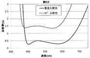
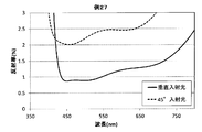
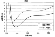
- Sectional drawing which shows one Embodiment of a glass laminated body. Sectional drawing which shows the antireflection layer of the glass laminated body shown in FIG. The figure which shows the measurement result of the spectral reflectance of Example 21. The figure which shows the measurement result of the spectral reflectance of Example 22. The figure which shows the measurement result of the spectral reflectance of Example 23. The figure which shows the measurement result of the spectral reflectance of Example 24. The figure which shows the measurement result of the spectral reflectance of Example 25. The figure which shows the measurement result of the spectral reflectance of Example 26. The figure which shows the measurement result of the spectral reflectance of Example 27. The figure which shows the measurement result of the spectral reflectance of Example 28.
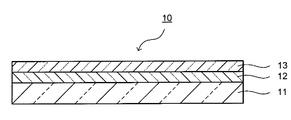
- FIG. 1 is a cross-sectional view showing an embodiment of a glass laminate.
- FIG. 2 is sectional drawing which shows the antireflection layer of the glass laminated body shown in FIG.
- the glass laminate 10 has, for example, a glass substrate 11, an antireflection layer 12, and an antifouling layer 13.
- the antireflection layer 12 and the antifouling layer 13 are provided in this order on one main surface side of the glass substrate 11.
- the glass laminate 10 has a minimum absorbance of 0.01 or more at a wavelength of 380 to 780 nm.
- the minimum value is 0.01 or more
- the appearance of the glass laminate 10 is colored.
- the antireflection layer 12 is provided, so that the depth of the black or the rich color is given and the design is improved.
- the color of the glass laminate 10 is black or a dense color
- things such as gloss and whiteness on the surface are suppressed, and a deep color can be obtained.
- the glass substrate 11 is made of a glass material, and makes the minimum absorbance of the glass laminate 10 at a wavelength of 380 to 780 nm 0.01 or more. From the viewpoint of setting the minimum absorbance of the glass laminate 10 at a wavelength of 380 to 780 nm to 0.01 or more, the minimum absorbance of the glass substrate 11 at a wavelength of 380 to 780 nm is preferably 0.01 or more. As such a glass substrate 11, colored glass is preferable.
- coloring component examples include metal oxides such as Co, Mn, Fe, Ni, Cu, Cr, V, Bi, Se, Ti, Ce, Er, and Nd.
- metal oxides such as Co, Mn, Fe, Ni, Cu, Cr, V, Bi, Se, Ti, Ce, Er, and Nd.
- the content of the coloring component is preferably 0.001 to 7% in terms of oxide-based molar percentage in the colored glass.
- content of a coloring component is less than 0.001%, the effect as a coloring component cannot fully be acquired.
- the minimum absorbance of the glass substrate 11 at a wavelength of 380 to 780 nm does not become 0.01 or more, and as a result, the minimum absorbance of the glass laminate 10 at a wavelength of 380 to 780 nm may not become 0.01 or more. There is.
- the content of the coloring component is preferably 0.1% or more, more preferably 0.2% or more, still more preferably 1% or more, and particularly preferably 2% or more. Moreover, when content of a coloring component exceeds 7%, there exists a possibility that glass may become unstable and may cause devitrification.
- the content of the coloring component is preferably 5% or less, more preferably 4% or less, from the viewpoint of the stability of the glass.
- the colored glass together with the coloring components, is expressed in terms of a molar percentage on the basis of oxide, with SiO 2 being 55 to 80%, Al 2 O 3 being 0 to 16%, B 2 O 3 being 0 to 12%, and Na 2 O being 5 ⁇ 20%, K 2 O 0 ⁇ 8%, MgO 0 ⁇ 15%, CaO 0 ⁇ 15%, ⁇ RO (R is Mg, Ca, Sr, Ba, Zn) 0 ⁇ 18%, ZrO 2 Is preferably contained in an amount of 0-5%.
- the composition of the glass other than the coloring components in the colored glass will be described using the mole percentage display content unless otherwise specified.
- SiO 2 is a component constituting the skeleton of the glass and is essential. If it is less than 55%, the stability and weather resistance of the glass may be lowered. Preferably it is 60% or more, more preferably 65% or more. If it exceeds 80%, the viscosity of the glass may increase and the meltability may decrease. Preferably it is 75% or less, More preferably, it is 70% or less.
- Al 2 O 3 is a component that improves the weather resistance and chemical strengthening properties of the glass, and is not essential, but can be contained as necessary. When it is 1% or more, weather resistance is improved, which is preferable. More preferably, it is 2% or more, and further preferably 3% or more. If it exceeds 16%, the viscosity of the glass tends to be high, and homogeneous melting may be difficult. Preferably it is 14% or less, More preferably, it is 12% or less.
- B 2 O 3 is a component for improving the weather resistance of glass, but not necessarily be contained as necessary. If it is 4% or more, the weather resistance is remarkably improved, which is preferable. More preferably, it is 5% or more, and further preferably 6% or more. If it exceeds 12%, striae due to volatilization may occur and the yield may decrease. Preferably it is 11% or less, More preferably, it is 10% or less.
- Na 2 O is a component that improves the meltability of the glass, and is contained in order to form a surface compressive stress layer by ion exchange. If it is less than 5%, the meltability is poor, and it may be difficult to form a desired surface compressive stress layer by ion exchange. Preferably it is 7% or more, More preferably, it is 8% or more. If it exceeds 20%, the weather resistance may decrease. Preferably it is 18% or less, More preferably, it is 17% or less.
- K 2 O is not essential, but is preferably a component that improves the meltability of the glass and has an effect of increasing the ion exchange rate in chemical strengthening. If it is 0.01% or more, the meltability, the ion exchange rate and the like are remarkably improved, which is preferable. More preferably, it is 0.1% or more. If it exceeds 8%, the weather resistance may decrease. Preferably it is 6% or less, More preferably, it is 5% or less.
- MgO is a component that improves the meltability of the glass, and is not essential, but can be contained if necessary. If it is 3% or more, the meltability is remarkably improved, which is preferable. More preferably, it is 4% or more. If it exceeds 15%, the weather resistance may deteriorate. Preferably it is 13% or less, More preferably, it is 12% or less.
- CaO is a component that improves the meltability of the glass and can be contained as necessary. If it is 0.01% or more, the meltability is remarkably improved, which is preferable. More preferably, it is 0.1% or more. If it exceeds 15%, the chemical strengthening properties may deteriorate. Preferably it is 13% or less, More preferably, it is 12% or less.
- SrO, BaO, and ZnO are also components that improve the meltability of the glass.
- ⁇ RO total content of these ROs
- the meltability is improved, which is preferable. More preferably, it is 3% or more, and further preferably 5% or more. If it exceeds 18%, the weather resistance is lowered. Preferably it is 15% or less, More preferably, it is 13% or less, More preferably, it is 11% or less.
- ZrO 2 is a component that increases the ion exchange rate, and is not essential, but can be contained in a range of 5% or less. If it exceeds 5%, the meltability may be deteriorated and remain in the glass as an unmelted product.
- Various molding methods can be adopted for molding colored glass. Specific examples include a downdraw method, a float method, a rollout method, and a press method. Examples of the downdraw method include an overflow downdraw method, a slot down method, and a redraw method.
- the colored glass may be chemically strengthened by ion exchange treatment to have high strength. Chemical strengthening increases the strength by forming a compressive stress layer on the surface layer of glass. Specifically, an alkali metal ion having a small ionic radius is exchanged with an alkali metal ion having a larger ionic radius at the glass transition temperature or lower.
- alkali metal ions having a small ion radius examples include Li ions and Na ions.
- examples of the alkali metal ion having a small ion radius include Li ion and Na ions.
- examples of the alkali metal ion having a larger ion radius include Na ion and K ion.
- examples of the alkali metal ion having a larger ion radius include K ion.
- the chemical strengthening is performed, for example, by immersing glass in a heated sodium nitrate (NaNO 3 ) molten salt or potassium nitrate (KNO 3 ) molten salt.
- NaNO 3 sodium nitrate
- KNO 3 potassium nitrate
- the conditions for chemical strengthening can be appropriately selected depending on the thickness of the glass, but the following conditions are usually preferred.
- the treatment temperature for chemical strengthening is preferably 350 to 550 ° C., more preferably 400 to 500 ° C.
- the chemical strengthening treatment time is preferably 0.5 to 144 hours, and more preferably 1 to 24 hours.
- the surface compressive stress layer In order to make the effect of improving the strength by chemical strengthening effective, it is preferable to make the surface compressive stress layer deeper than the microcracks generated on the surface of the glass. Here, microcracks are likely to occur when the surface of glass is roughened. For these reasons, the thickness of the surface compressive stress layer is preferably 6 ⁇ m or more.
- glass is easy to break when scratches generated during its use exceed the thickness of the surface compressive stress layer. For this reason, it is preferable to thicken the surface compressive stress layer. Specifically, 10 ⁇ m or more is more preferable, 15 ⁇ m or more is further preferable, 20 ⁇ m or more is further preferable, and 30 ⁇ m or more is particularly preferable.
- the depth of the surface compressive stress layer is preferably 70 ⁇ m or less, more preferably 60 ⁇ m or less, further preferably 50 ⁇ m or less, and particularly preferably 40 ⁇ m or less.
- the depth of the surface compressive stress layer is obtained as follows.
- the alkali ion concentration analysis of the depth direction of glass is performed by EPMA (electron probe microanalyzer, electron beam microanalyzer).
- EPMA electron probe microanalyzer, electron beam microanalyzer
- potassium ion concentration analysis is performed.
- the potassium ion diffusion depth obtained by the measurement is regarded as the depth of the surface compressive stress layer.
- the glass substrate 11 preferably has a surface roughness Ra measured in accordance with JIS B0633 (2001) of 0.2 to 1 ⁇ m.
- a surface roughness Ra of 0.2 ⁇ m or more is preferable because strength is improved. Further, when the surface roughness Ra is 1 ⁇ m or less, a change in appearance and texture is suppressed, and a desired color can be easily obtained.
- the surface roughness Ra can be adjusted by a physical method such as sand blasting or loose abrasive polishing using an abrasive, or a chemical method immersed in an etching solution.
- the surface roughness Ra can be measured with a laser microscope (for example, model number: VK8550, manufactured by Keyence Corporation).
- the thickness of the glass substrate 11 can be appropriately selected according to the use. From the viewpoint of securing strength, it is preferably 0.1 mm or more, more preferably 0.2 mm or more, and further preferably 0.5 mm or more. Moreover, 10 mm or less is preferable, 2.0 mm or less is more preferable, and 1.2 mm or less is further more preferable.
- the glass substrate 11 preferably has the following optical characteristics.
- the minimum absorbance at a wavelength of 380 to 780 nm is preferably 0.01 or more, more preferably 0.2 or more, further preferably 0.7 or more, and particularly preferably 1.0 or more.
- the minimum value is 0.01 or more, since the depth of the color of the glass laminated body 10 increases, it is preferable. Since the depth of the color of the glass laminated body 10 increases so that the said minimum value becomes large, it is preferable.
- the average value of absorbance at wavelengths of 380 to 780 nm is preferably 0.1 or more, more preferably 0.5 or more, still more preferably 2.0 or more, and particularly preferably 3.0 or more.
- the average value is preferable because the color depth of the glass laminate 10 increases as the average value increases.
- the lightness L * of the reflected light from the F2 light source of the L * a * b * color system is preferably less than 40. When the lightness L * is less than 40, it becomes close to black. For this reason, when the antireflection layer 12 is provided, the effect of increasing the color depth is increased.
- the lightness L * is more preferably 35 or less, and further preferably 30 or less.
- the lightness L * is preferably 1 or more, and more preferably 1.5 or more.
- the antireflection layer 12 is provided to add depth to the color of the glass laminate 10.
- the antireflection layer 12 is formed by laminating a high refractive index layer 121 and a low refractive index layer 122.
- the high refractive index layer 121 is a layer having a refractive index of 1.9 or more at a wavelength of 550 nm.
- the low refractive index layer 122 is a layer having a refractive index of 1.6 or less at a wavelength of 550 nm.
- the antireflection layer 12 is preferably provided on the main surface side which is the outside when the glass substrate 11 is used as a casing or the like of an electronic device.
- the antireflection layer 12 may include one high-refractive index layer 121 and one low-refractive index layer 122, or may include two or more layers. When two or more high refractive index layers 121 and low refractive index layers 122 are included, a form in which the high refractive index layers 121 and the low refractive index layers 122 are alternately stacked is preferable.
- the total number of layers of the high refractive index layer 121 and the low refractive index layer 122 is preferably 3 to 10, more preferably 2 to 6, and further preferably 2 to 4.
- the materials of the high refractive index layer 121 and the low refractive index layer 122 can be appropriately selected in consideration of antireflection performance, productivity, and the like.
- the high refractive index layer 121 As a constituent material of the high refractive index layer 121, niobium oxide (Nb 2 O 5 ), titanium oxide (TiO 2 ), zirconium oxide (ZrO 2 ), silicon nitride (SiN X ), tantalum oxide (Ta 2 O 5 ), etc. Is mentioned. Only 1 type may be used for these and 2 or more types may be used.
- the refractive index of the high refractive index layer 121 is preferably 1.9 to 2.7.
- Examples of the constituent material of the low refractive index layer 122 include silicon oxide (SiO 2 ), a composite oxide of Si and Sn, a composite oxide of Si and Zr, and a composite oxide of Si and Al. Only 1 type may be used for these and 2 or more types may be used.
- the refractive index of the low refractive index layer 122 is preferably 1.3 to 1.6.
- the high refractive index layer 121 is made of niobium oxide or tantalum oxide and the low refractive index layer 122 is made of silicon oxide.
- the high refractive index layer 121 is made of silicon nitride
- the low refractive index layer 122 is a composite oxide of Si and Sn, a composite oxide of Si and Zr, or It is preferably made of a complex oxide of Si and Al.
- the geometrical film thickness of the high refractive index layer 121 is preferably 5 nm or more, and more preferably 10 nm or more. Moreover, 200 nm or less is preferable respectively, and 150 nm or less is more preferable. Further, the geometric film thickness of the low refractive index layer 122 is preferably 5 nm or more, and more preferably 10 nm or more. Moreover, 150 nm or less is preferable respectively, and 100 nm or less is more preferable.
- the antireflection layer 12 preferably has a surface protective layer 123 as the uppermost layer in order to improve scratch resistance and the like.
- the surface protective layer 123 is made of, for example, an oxide containing at least one of zirconium and titanium and at least one of boron and silicon.
- Preferred examples include ZrBxOy, ZrSizOy, ZrBxSizOy, and TiSizOy.
- complex oxides containing zirconium and silicon ZrSizOy, ZrBxSizOy
- ZrBxSizOy complex oxides containing zirconium and silicon
- the hardness and refractive index of the surface protective layer 123 can be changed depending on the content ratio of boron, silicon, and oxygen and the film forming conditions. Therefore, it is preferable to select the content ratio of boron, silicon, and oxygen and the film forming conditions so that the desired hardness and refractive index are obtained.
- the film formation method of the antireflection layer 12 is not particularly limited, and various film formation methods can be used. Examples of the film forming method include pulse sputtering, AC sputtering, and digital sputtering. Pulse sputtering and AC sputtering are preferable because a dense film can be obtained.
- the antifouling layer 13 imparts antifouling properties and further adds color depth, and is provided as necessary.
- the antifouling layer 13 is made of, for example, a fluorine-containing organosilicon compound.
- a fluorine-containing organosilicon compound those imparting antifouling property, water repellency, or oil repellency can be used.
- fluorine-containing organosilicon compound for example, a fluorine-containing organosilicon compound having one or more groups selected from a polyfluoropolyether group, a polyfluoroalkylene group, and a polyfluoroalkyl group is preferable.
- the polyfluoropolyether group means a divalent group having a structure in which polyfluoroalkylene groups and etheric oxygen atoms are alternately bonded.
- fluorine-containing organosilicon compound having one or more groups selected from a polyfluoropolyether group, a polyfluoroalkylene group, and a polyfluoroalkyl group are represented by the following general formulas (I) to (V). Compounds.
- Rf is a linear polyfluoroalkyl group having 1 to 16 carbon atoms
- X is a hydrogen atom or a lower alkyl group having 1 to 5 carbon atoms
- R1 is a hydrolyzable group or halogen atom
- m is 1 to An integer of 50
- n is an integer of 0 to 2
- p is an integer of 1 to 10.
- Examples of the alkyl group in Rf include a methyl group, an ethyl group, an n-propyl group, an isopropyl group, and an n-butyl group.
- Examples of the lower alkyl group for X include a methyl group, an ethyl group, an n-propyl group, an isopropyl group, and an n-butyl group.
- Examples of the hydrolyzable group for R1 include an amino group and an alkoxy group.
- Examples of the halogen atom for R1 include fluorine, chlorine, bromine and iodine.
- m is preferably an integer of 1 to 30.
- n is preferably an integer of 1 to 2.
- p is preferably an integer of 1 to 8.
- q is 1 or more, preferably an integer of 2 to 20.
- Examples of the compound represented by the general formula (II) include n-trifluoro (1,1,2,2-tetrahydro) propylsilazane (n-CF 3 CH 2 CH 2 Si (NH 2 ) 3 ), n-heptafluoro ( 1,1,2,2-tetrahydro) pentylsilazane (nC 3 F 7 CH 2 CH 2 Si (NH 2 ) 3 ) and the like.
- q ′ is an integer of 1 or more, preferably 1-20.
- Examples of the compound represented by the general formula (III) include 2- (perfluorooctyl) ethyltrimethoxysilane (nC 8 F 17 CH 2 CH 2 Si (OCH 3 ) 3 ) and the like.
- R f2 is 2 represented by — (OC 3 F 6 ) s — (OC 2 F 4 ) t — (OCF 2 ) u — (s, t and u are each independently an integer of 0 to 300).
- Is a monovalent linear polyfluoropolyether group and R 2 and R 3 are each independently a monovalent hydrocarbon group having 1 to 8 carbon atoms.
- X 2 and X 3 are hydrolyzable groups or halogen atoms, and may be the same or different, d and e are independently integers of 1 to 2, and c and f are 1 to 5 (preferably 1 ⁇ 2) are mutually independent integers, and a and b are 2 ⁇ 3 mutually independent integers.
- Examples of the monovalent hydrocarbon group for R 2 and R 3 include a methyl group, an ethyl group, an n-propyl group, an isopropyl group, and an n-butyl group.
- Examples of the hydrolyzable group for X 2 and X 3 include an amino group, an alkoxy group, an acyloxy group, an alkenyloxy group, and an isocyanate group.
- Examples of the halogen atom for X 2 and X 3 include a fluorine atom, a chlorine atom, a bromine atom, and an iodine atom.
- s + t + u is preferably 20 to 200, more preferably 25 to 100.
- R 2 and R 3 are more preferably a methyl group, an ethyl group, or a butyl group.
- the hydrolyzable group represented by X 2 or X 3 is more preferably an alkoxy group having 1 to 6 carbon atoms, particularly preferably a methoxy group or an ethoxy group. Further, a and b are each preferably 3.
- v is an integer of 1 to 3
- w, y and z are each independently an integer of 0 to 200
- h is 1 or 2
- i is an integer of 2 to 20
- X 4 Is a hydrolyzable group
- R 4 is a linear or branched hydrocarbon group having 1 to 22 carbon atoms
- k is an integer of 0 to 2.
- w + y + z is preferably 20 to 300, more preferably 25 to 100. Further, i is preferably 2 to 10.
- X 4 is preferably an alkoxy group having 1 to 6 carbon atoms, more preferably a methoxy group or an ethoxy group. R 4 is preferably an alkyl group having 1 to 10 carbon atoms.
- fluorine-containing organosilicon compound having one or more groups selected from a polyfluoropolyether group, a polyfluoroalkylene group, and a polyfluoroalkyl group commercially available products can be used.
- examples of such products include KP-801 (trade name, manufactured by Shin-Etsu Chemical Co., Ltd.), KY178 (trade name, manufactured by Shin-Etsu Chemical Co., Ltd.), KY-130 (trade name, manufactured by Shin-Etsu Chemical Co., Ltd.), KY185 (trade name).
- Otsuru (registered trademark) DSX and OPTOOL (registered trademark) AES both trade names, manufactured by Daikin are preferable.
- the method for forming the antifouling layer 13 is not particularly limited, but it is preferable to form the film by vacuum deposition using the above materials.
- the geometrical film thickness of the antifouling layer 13 is preferably 1 nm or more from the viewpoint of effectively imparting antifouling properties. Further, the geometric film thickness of the antifouling layer 13 is preferably 15 nm or less, and more preferably 10 nm or less, from the viewpoint of productivity and the like.
- the glass laminate 10 of the present invention preferably has the following optical characteristics.
- the optical properties of the glass laminate 10 are measured in a state where at least the antireflection layer 12 is provided on the glass substrate 11. For example, when the glass laminated body 10 has the antireflection layer 12 and the antifouling layer 13, it measures in the state in which the antireflection layer 12 and the antifouling layer 13 were provided.
- the minimum absorbance at a wavelength of 380 to 780 nm is preferably 0.01 or more, more preferably 0.2 or more, further preferably 0.7 or more, and particularly preferably 1.0 or more.
- the minimum value is 0.01 or more, since the depth of the color of the glass laminated body 10 increases, it is preferable. Since the depth of the color of the glass laminated body 10 increases so that the said minimum value becomes large, it is preferable.
- the average value of absorbance at wavelengths of 380 to 780 nm is preferably 0.1 or more, more preferably 0.5 or more, still more preferably 2.0 or more, and particularly preferably 3.0 or more.
- the average value is preferable because the color depth of the glass laminate 10 increases as the average value increases.
- the minimum value of the spectral reflectance of normal incident light at a wavelength of 380 to 780 nm on the side where the antireflection layer 12 is provided with respect to the glass substrate 11 is preferably 3% or less.
- the minimum value is preferable because the color depth increases as the value becomes lower.
- the minimum value is preferably 2% or less, and more preferably 1% or less.
- the average value of the spectral reflectance of normal incident light at a wavelength of 380 to 780 nm on the side where the antireflection layer 12 is provided with respect to the glass substrate 11 is preferably 3% or less.
- the average value of 3% or less is particularly preferable because the reflection of illumination light or the like on the surface is suppressed and the color depth is increased.
- a lower average value is preferable because the color depth increases.
- the average value is preferably 2% or less, and more preferably 1.5% or less. Usually 0.2% is sufficient.
- the average value of the spectral reflectance of vertically incident light at a wavelength of 440 to 620 nm is preferably 0.3 to 2%. When the average value is 0.3 to 2%, it is possible to suppress illumination light or the like from being reflected on the glass laminate 10.
- the lightness L * of the reflected light by the F2 light source of the L * a * b * color system on the side where the antireflection layer 12 is provided with respect to the glass substrate 11 is preferably less than 25.
- a lightness L * of less than 25 is preferable because a sufficiently deep color can be obtained.
- the lightness L * is more preferably 20 or less, further preferably 15 or less, particularly preferably 10 or less, and most preferably 5 or less. Further, the lightness L * is preferably 1 or more, and more preferably 1.5 or more.
- the color of the reflected light of the glass laminate 10 may be either achromatic or chromatic. It is preferable that the glass laminated body 10 has the following optical characteristics according to the color of reflected light.
- the glass laminate 10 When making the reflected light color achromatic, the glass laminate 10 preferably has the following optical characteristics.
- the difference between the maximum value and the average value of the spectral reflectance of normal incidence light at a wavelength of 420 to 680 nm is preferably 0.5% or less, more preferably 0.4% or less, and further preferably 0.3% or less.
- the difference is 0.5% or less
- the reflected light is preferably an achromatic color having no specific color tone.
- the difference between the maximum value and the average value of the spectral reflectance of normal incidence light at a wavelength of 440 to 620 nm is preferably 0.3% or less, more preferably 0.25% or less, and further preferably 0.2% or less.
- the difference is 0.3% or less, when reflected light such as illumination light is recognized by the glass laminate 10, the reflected light is preferably an achromatic color having no specific color tone.
- the difference between the maximum value and the average value of the spectral reflectance of 45 ° incident light at a wavelength of 420 to 680 nm is preferably 1.0% or less, more preferably 0.9% or less, and even more preferably 0.8% or less.
- the difference is 1.0% or less, when reflected light such as illumination light is recognized by the glass laminate 10, the reflected light is preferably an achromatic color having no specific color tone.
- the difference between the maximum value and the average value of the spectral reflectance of 45 ° incident light at wavelengths of 440 to 620 nm is preferably 0.6% or less, more preferably 0.55% or less, and even more preferably 0.5% or less.
- the difference is 0.6% or less
- the reflected light is preferably an achromatic color having no specific color tone.
- the glass laminate 10 When making the color of reflected light chromatic, the glass laminate 10 preferably has the following optical characteristics.
- the difference between the maximum value and the average value of the spectral reflectance of normal incidence light at a wavelength of 420 to 680 nm is preferably more than 0.5%, more preferably more than 0.6%, still more preferably more than 0.7%.
- the difference exceeds 0.5%, when reflected light such as illumination light is recognized by the glass laminate 10, the reflected light has a specific color tone. Can be adjusted.
- the difference between the maximum value and the average value of the spectral reflectance of normal incidence light at a wavelength of 440 to 620 nm is preferably more than 0.3%, more preferably more than 0.4%, still more preferably more than 0.5%.
- the difference exceeds 0.3%, when reflected light such as illumination light is recognized by the glass laminate 10, the reflected light has a specific color tone. Can be adjusted.
- the difference between the maximum value and the average value of the spectral reflectance of 45 ° incident light at a wavelength of 420 to 680 nm is preferably more than 1.0%, more preferably more than 1.1%, and still more preferably more than 1.2%.
- the difference exceeds 1.0%, when reflected light such as illumination light is recognized by the glass laminate 10, the reflected light has a specific color tone. Can be adjusted.
- the difference between the maximum value and the average value of the spectral reflectance of 45 ° incident light at a wavelength of 440 to 620 nm is preferably more than 0.6%, more preferably more than 0.7%, and still more preferably more than 0.8%.
- the difference exceeds 0.6%, when reflected light such as illumination light is recognized by the glass laminate 10, the reflected light has a specific color tone. Can be adjusted.
- the glass laminate 10 can be suitably used for the exterior of a portable electronic device.
- a portable electronic device is a concept that encompasses communication devices and information devices that are carried around. For example, a communication terminal, a broadcast receiver, etc. are mentioned as a communication apparatus.
- Communication terminals include mobile phones, PHS (Personal Handy-phone System), smartphones, PDAs (Personal Data Assistance), PNDs (Portable Navigation Devices, portable car navigation systems), and the like.
- Examples of the broadcast receiver include a portable radio, a portable television, and a one-segment receiver.
- the glass laminate 10 can be used for a stationary electronic device or an electronic device installed in a car. By using the glass laminate 10 for the exterior of these portable and stationary electronic devices, the design can be improved. Furthermore, the glass laminate 10 can also be used for the exterior of products other than electronic devices.
- the product other than the electronic device is a building material or a device used indoors, and is not particularly limited to furniture, various housing facilities, and the like.
- the casing may be configured using only the glass laminate 10, or the glass laminate 10 may be disposed on the outer surface of a casing made of another material. You may stick together.
- Example 1 to Example 11 Glass substrates A to D having a glass composition, absorbance, reflectance, and chromaticity as shown in Table 1 were prepared. The absorbance, reflectance, and chromaticity were measured according to the measurement method described later. And the test piece which has a structure as shown in Table 2 using these glass substrates was manufactured.
- Example 1 Example 3, and Example 6, only the antireflection layer was formed on one main surface of the glass substrate to obtain test pieces.
- Example 2 Example 4, Example 5, and Example 7, an antireflection layer and an antifouling layer were sequentially formed on one main surface of the glass substrate to obtain test pieces.
- Example 8 to 11 test pieces were used as glass substrates without forming any antireflection layer or antifouling layer.
- Examples 1 to 7 are examples of the present invention, and examples 8 to 11 are comparative examples of the present invention.
- the antireflection layer is formed by sequentially forming a first high refractive index layer, a first low refractive index layer, a second high refractive index layer, and a second low refractive index layer as shown below. Formed.
- pulse sputtering was performed using a niobium oxide target while introducing a mixed gas obtained by mixing 10 vol% oxygen gas into argon gas.
- a first high refractive index layer made of niobium oxide (niobium) having a geometric thickness of 14 nm was formed on the glass substrate.
- the product name “NBO target” manufactured by AGC Ceramics Company was used as the niobium oxide target.
- pulse sputtering was performed under the conditions of pressure 0.3 Pa, frequency 20 kHz, power density 3.8 W / cm 2 , and inversion pulse width 5 ⁇ sec.
- pulse sputtering was performed using a silicon target while introducing a mixed gas obtained by mixing 40% by volume of oxygen gas with argon gas.
- a first low refractive index layer made of silicon oxide (silica) having a geometric thickness of 35 nm was formed on the first high refractive index layer.
- the pulse sputtering was performed under the conditions of pressure 0.3 Pa, frequency 20 kHz, power density 3.8 W / cm 2 , and inversion pulse width 5 ⁇ sec.
- pulse sputtering was performed using a niobium oxide target while introducing a mixed gas obtained by mixing 10 vol% oxygen gas into argon gas.
- a second high refractive index layer made of niobium oxide (niobium) having a geometric thickness of 118 nm was formed on the first low refractive index layer.
- the product name “NBO target” manufactured by AGC Ceramics Company was used as the niobium oxide target.
- pulse sputtering was performed under the conditions of pressure 0.3 Pa, frequency 20 kHz, power density 3.8 W / cm 2 , and inversion pulse width 5 ⁇ sec.
- pulse sputtering was performed using a silicon target while introducing a mixed gas obtained by mixing 40% by volume of oxygen gas with argon gas.
- a second low refractive index layer made of silicon oxide (silica) having a geometric thickness of 84 nm was formed on the second high refractive index layer.
- the pulse sputtering was performed under the conditions of pressure 0.3 Pa, frequency 20 kHz, power density 3.8 W / cm 2 , and inversion pulse width 5 ⁇ sec.
- the antifouling layer was formed as follows.
- a glass substrate on which an antireflection layer was formed was placed in a vacuum chamber, and the composition was supplied from a heating container through a nozzle connected to the vacuum chamber.
- the geometric thickness was measured with a crystal resonator monitor installed in a vacuum chamber, and the composition was supplied until the geometric thickness reached 7 nm.
- the glass substrate was taken out from the vacuum chamber, and the glass substrate was placed on a hot plate with the film formation surface facing upward, and heat treatment was performed in air at 150 ° C. for 60 minutes. Thereby, the antifouling layer was formed on the antireflection layer.
- the spectral transmittance of normal incident light of each test piece was measured using an ultraviolet-visible near-infrared spectrophotometer V-570 manufactured by JASCO Corporation. In the measurement of spectral reflectance, measurement light was incident on the glass substrate from the main surface side where the antireflection layer was formed. Then, the minimum value and the average value of the reflectance at a wavelength of 380 to 780 nm were obtained from this spectral transmittance.
- the chromaticity of the reflected light of the L * a * b * color system normalized by CIE was measured.
- the F2 light source was used as the light source, and the chromaticity of the reflected light on the main surface side where the antireflection layer was formed on the glass substrate was measured.
- a spectrocolorimeter manufactured by X-Rite, Colori7 was used. The measurement was performed by placing a white resin plate on the back side of the glass (the back side of the surface irradiated with light from the light source).
- Example 21 to Example 28 Test pieces of Examples 21 to 28 were produced as follows. Examples 21 to 28 are all examples of the present invention.
- Example 21 As shown in Table 3, a high refractive index layer made of niobium oxide and a low refractive index layer made of silicon oxide are alternately formed on the surface of the glass substrate A (plate thickness: 1.0 mm) shown in Table 1 as shown in Table 3.
- a test piece was manufactured by film formation. The number of layers in the table is indicated with the glass substrate side as the first layer.
- the high refractive index layer made of niobium oxide was formed by AC sputtering using a niobium target and introducing a mixed gas of argon gas and oxygen gas.
- the low refractive index layer made of silicon oxide was formed by AC sputtering using a silicon target and introducing a mixed gas of argon gas and oxygen gas. The antifouling layer was not formed.
- Test pieces were produced in the same manner as in Example 21 except that the thickness of the antireflection layer was changed as shown in Table 4.
- Test pieces were produced in the same manner as in Example 21 except that the thickness of the antireflection layer was changed as shown in Table 5.
- Test pieces were produced in the same manner as in Example 21 except that the thickness of the antireflection layer was changed as shown in Table 6.
- Test pieces were produced in the same manner as in Example 21 except that the thickness of the antireflection layer was changed as shown in Table 7.
- Example 26 A test piece was produced in the same manner as in Example 21 except that the thickness of the antireflection layer was changed as shown in Table 8.
- Example 27 A test piece was produced in the same manner as in Example 21 except that the thickness of the antireflection layer was changed as shown in Table 9.
- Example 28 A test piece was produced in the same manner as in Example 21 except that the thickness of the antireflection layer was changed as shown in Table 10.
- the spectral transmittance of normal incident light was measured for each test piece, and the maximum value, the average value, and the difference between the reflectance at a wavelength of 440 to 620 nm, the maximum value, the average value of the reflectance at a wavelength of 420 to 680 nm, and These differences, the minimum value and the average value of the reflectance at wavelengths of 380 to 780 nm were determined.
- the spectral transmittance of 45 ° incident light was measured for each test piece, and the maximum and average values of reflectance at wavelengths of 440 to 620 nm, and their differences, and the maximum and average values of reflectance at wavelengths of 420 to 680 nm. Values and their differences were determined.
- an ultraviolet-visible near-infrared spectrophotometer V-570 manufactured by JASCO Corporation was used for the measurement of the spectral transmittance.
- MIN represents a minimum value
- MAX represents a maximum value
- AVG represents an average value
- WT is achromatic
- BL is blue
- GN is green
- BG blue-green
- LB is light blue
- LV is light purple
- RV magenta
- LR magenta
- BE represents beige
- YL represents yellow
- LG represents light green.
- the color of the reflected light can be adjusted to an achromatic color or a chromatic color by adjusting the reflectance.
- a chromatic color a specific color can be adjusted.
- SYMBOLS 10 Glass laminated body, 11 ... Glass base material, 12 ... Antireflection layer, 13 ... Antifouling layer, 121 ... High refractive index layer, 122 ... Low refractive index layer, 123 ... Surface protective layer.
Abstract
Provided is a glass laminate which provides excellent aesthetic appearance and is well-suited for exterior applications such as casings for electronic devices. The glass laminate comprises a glass substrate and an antireflection layer that is laminated on the glass substrate. The glass laminate has a minimum absorbance in a wavelength of 380-780 nm of 0.01 or greater.
Description
本発明は、ガラス積層体および携帯型電子機器に係り、特に意匠性に優れるガラス積層体とこれを用いた携帯型電子機器とに関する。
The present invention relates to a glass laminate and a portable electronic device, and particularly to a glass laminate excellent in design and a portable electronic device using the same.
携帯電話をはじめとする電子機器の筐体等については、装飾性、耐傷性、加工性、コスト等、様々な要因を考慮して、樹脂、金属等の素材から適宜のものが選択されている。
As for the casings of electronic devices such as mobile phones, appropriate materials are selected from materials such as resin and metal in consideration of various factors such as decoration, scratch resistance, workability, and cost. .
近年、電子機器の筐体等を構成する素材として、従来は用いられていなかったガラスを用いることが試みられている。電子機器の筐体等を構成する素材にガラスを用いることにより、透明感のある独特の装飾効果を得ることができる(例えば、特許文献1参照。)。
In recent years, attempts have been made to use glass, which has not been used in the past, as a material constituting the casing of an electronic device. By using glass as a material that constitutes a housing or the like of an electronic device, a unique decorative effect with a transparent feeling can be obtained (for example, see Patent Document 1).
一方、電子機器の筐体等を構成する素材にガラスを用いた場合、必ずしも遮光性が十分でない。例えば、内部に光源等が設けられたときに、この内部の光源等が外部から認識されやすくなる。このため、電子機器の筐体等を構成する素材に、所定の吸光係数を有するガラスを用いることが試みられている(例えば、特許文献2参照。)。
On the other hand, when glass is used as the material constituting the casing of the electronic device, the light shielding property is not always sufficient. For example, when a light source or the like is provided inside, the light source or the like inside is easily recognized from the outside. For this reason, it has been attempted to use glass having a predetermined extinction coefficient as a material constituting a housing or the like of an electronic device (for example, see Patent Document 2).
従来、電子機器の筐体等を構成する素材にガラスを用いることが試みられている。電子機器の筐体等を構成する素材にガラスを用いることにより、ガラス独特の装飾効果を得ることができる。しかし、このような外装用途に用いられるガラスについては、さらに意匠性を良好にすることが求められている。
Conventionally, it has been attempted to use glass as a material constituting the casing of an electronic device. By using glass as a material that constitutes a housing or the like of an electronic device, a decorative effect peculiar to glass can be obtained. However, for the glass used for such exterior applications, it is required to further improve the design.
本発明は、上記課題を解決するためになされたものであって、電子機器の筐体等、外装用途に好適に用いられるものであって、意匠性に優れるガラス積層体の提供を目的としている。
The present invention has been made to solve the above-described problems, and is suitable for exterior use such as a casing of an electronic device, and aims to provide a glass laminate having excellent design properties. .
本発明のガラス積層体は、ガラス基材と、上記ガラス基材に積層される反射防止層とを有する。また、本発明のガラス積層体は、波長380~780nmにおける吸光度の最小値が0.01以上である。
The glass laminate of the present invention has a glass substrate and an antireflection layer laminated on the glass substrate. In the glass laminate of the present invention, the minimum absorbance at a wavelength of 380 to 780 nm is 0.01 or more.
本発明によれば、電子機器の筐体等に好適に用いられるものであって、意匠性に優れるガラス積層体を提供できる。特に、本発明によれば、色彩に深みのあるガラス積層体を提供できる。
According to the present invention, it is possible to provide a glass laminate that is suitably used for a housing or the like of an electronic device and has excellent design properties. In particular, according to the present invention, a glass laminate having a deep color can be provided.
以下、本発明を実施するための形態について説明する。
図1は、ガラス積層体の一実施形態を示す断面図である。また、図2は、図1に示すガラス積層体の反射防止層を示す断面図である。 Hereinafter, modes for carrying out the present invention will be described.
FIG. 1 is a cross-sectional view showing an embodiment of a glass laminate. Moreover, FIG. 2 is sectional drawing which shows the antireflection layer of the glass laminated body shown in FIG.
ガラス積層体10は、例えば、ガラス基材11、反射防止層12、および防汚層13を有する。反射防止層12、防汚層13は、ガラス基材11の一方の主面側に、この順に設けられている。
The glass laminate 10 has, for example, a glass substrate 11, an antireflection layer 12, and an antifouling layer 13. The antireflection layer 12 and the antifouling layer 13 are provided in this order on one main surface side of the glass substrate 11.
ガラス積層体10は、波長380~780nmにおける吸光度の最小値が0.01以上である。上記最小値が0.01以上である場合、ガラス積層体10の外観が有色になる。このようにガラス積層体10の外観が有色となる場合、反射防止層12が設けられていることにより、その色彩に深みが与えられて意匠性が向上する。特に、ガラス積層体10の色彩が黒色や濃厚色のような場合、反射防止層12が設けられていることにより、その黒色や濃厚色に深みが与えられて意匠性が向上する。例えば、ガラス積層体10の色彩が黒色や濃厚色である場合、表面における艶や白みのようなものが抑制され、深みのある色彩を得ることができる。
The glass laminate 10 has a minimum absorbance of 0.01 or more at a wavelength of 380 to 780 nm. When the minimum value is 0.01 or more, the appearance of the glass laminate 10 is colored. Thus, when the external appearance of the glass laminated body 10 becomes colored, by providing the antireflection layer 12, the color is deepened and the design is improved. In particular, when the color of the glass laminate 10 is black or a dense color, the antireflection layer 12 is provided, so that the depth of the black or the rich color is given and the design is improved. For example, when the color of the glass laminate 10 is black or a dense color, things such as gloss and whiteness on the surface are suppressed, and a deep color can be obtained.
以下、ガラス積層体10の各構成部材について説明する。
Hereinafter, each component of the glass laminate 10 will be described.
ガラス基材11は、ガラス材料からなり、かつガラス積層体10の波長380~780nmにおける吸光度の最小値を0.01以上にするものである。ガラス積層体10の波長380~780nmにおける吸光度の最小値を0.01以上にする観点から、ガラス基材11の波長380~780nmにおける吸光度の最小値は0.01以上が好ましい。このようなガラス基材11としては、着色ガラスが好ましい。
The glass substrate 11 is made of a glass material, and makes the minimum absorbance of the glass laminate 10 at a wavelength of 380 to 780 nm 0.01 or more. From the viewpoint of setting the minimum absorbance of the glass laminate 10 at a wavelength of 380 to 780 nm to 0.01 or more, the minimum absorbance of the glass substrate 11 at a wavelength of 380 to 780 nm is preferably 0.01 or more. As such a glass substrate 11, colored glass is preferable.
着色ガラスとしては、ガラス中に着色成分を含有するものが好ましい。着色成分としては、Co、Mn、Fe、Ni、Cu、Cr、V、Bi、Se、Ti、Ce、Er、Nd等の金属酸化物が挙げられる。具体的には、Co3O4、MnO、MnO2、Fe2O3、NiO、CuO、Cu2O、Cr2O3、V2O5、Bi2O3、SeO2、TiO2、CeO2、Er2O3、Nd2O3等が挙げられる。着色成分は、1種のみを用いてもよいし、2種以上を用いてもよい。
As colored glass, what contains a coloring component in glass is preferable. Examples of the coloring component include metal oxides such as Co, Mn, Fe, Ni, Cu, Cr, V, Bi, Se, Ti, Ce, Er, and Nd. Specifically, Co 3 O 4 , MnO, MnO 2 , Fe 2 O 3 , NiO, CuO, Cu 2 O, Cr 2 O 3 , V 2 O 5 , Bi 2 O 3 , SeO 2 , TiO 2 , CeO 2 , Er 2 O 3 , Nd 2 O 3 and the like. Only 1 type may be used for a coloring component and 2 or more types may be used for it.
着色成分の含有量は、着色ガラス中、酸化物基準のモル百分率表示で0.001~7%が好ましい。着色成分の含有量が0.001%未満の場合、着色成分としての効果を十分に得ることができない。これにより、ガラス基材11の波長380~780nmにおける吸光度の最小値が0.01以上にならず、結果としてガラス積層体10の波長380~780nmにおける吸光度の最小値が0.01以上にならないおそれがある。
The content of the coloring component is preferably 0.001 to 7% in terms of oxide-based molar percentage in the colored glass. When content of a coloring component is less than 0.001%, the effect as a coloring component cannot fully be acquired. Thereby, the minimum absorbance of the glass substrate 11 at a wavelength of 380 to 780 nm does not become 0.01 or more, and as a result, the minimum absorbance of the glass laminate 10 at a wavelength of 380 to 780 nm may not become 0.01 or more. There is.
着色成分の含有量は、深みのある色彩を得る観点から、好ましくは0.1%以上、より好ましくは0.2%以上、さらに好ましくは1%以上、特に好ましくは2%以上である。また、着色成分の含有量が7%を超える場合、ガラスが不安定となり失透を生じるおそれがある。着色成分の含有量は、ガラスの安定性等の観点から、好ましくは5%以下、より好ましくは4%以下である。
From the viewpoint of obtaining a deep color, the content of the coloring component is preferably 0.1% or more, more preferably 0.2% or more, still more preferably 1% or more, and particularly preferably 2% or more. Moreover, when content of a coloring component exceeds 7%, there exists a possibility that glass may become unstable and may cause devitrification. The content of the coloring component is preferably 5% or less, more preferably 4% or less, from the viewpoint of the stability of the glass.
着色ガラスは、着色成分とともに、酸化物基準のモル百分率表示で、SiO2を55~80%、Al2O3を0~16%、B2O3を0~12%、Na2Oを5~20%、K2Oを0~8%、MgOを0~15%、CaOを0~15%、ΣRO(Rは、Mg、Ca、Sr、Ba、Zn)を0~18%、ZrO2を0~5%含有することが好ましい。以下、着色ガラスにおける着色成分以外のガラスの組成について、特に断らない限りモル百分率表示含有量を用いて説明する。
The colored glass, together with the coloring components, is expressed in terms of a molar percentage on the basis of oxide, with SiO 2 being 55 to 80%, Al 2 O 3 being 0 to 16%, B 2 O 3 being 0 to 12%, and Na 2 O being 5 ~ 20%, K 2 O 0 ~ 8%, MgO 0 ~ 15%, CaO 0 ~ 15%, ΣRO (R is Mg, Ca, Sr, Ba, Zn) 0 ~ 18%, ZrO 2 Is preferably contained in an amount of 0-5%. Hereinafter, the composition of the glass other than the coloring components in the colored glass will be described using the mole percentage display content unless otherwise specified.
SiO2は、ガラスの骨格を構成する成分であり必須である。55%未満では、ガラスの安定性、耐候性が低下するおそれがある。好ましくは60%以上、より好ましくは65%以上である。80%超では、ガラスの粘性が増大して溶融性が低下するおそれがある。好ましくは75%以下、より好ましくは70%以下である。
SiO 2 is a component constituting the skeleton of the glass and is essential. If it is less than 55%, the stability and weather resistance of the glass may be lowered. Preferably it is 60% or more, more preferably 65% or more. If it exceeds 80%, the viscosity of the glass may increase and the meltability may decrease. Preferably it is 75% or less, More preferably, it is 70% or less.
Al2O3は、ガラスの耐候性および化学強化特性を向上させる成分であり、必須ではないが必要に応じて含有できる。1%以上になると、耐候性が良好になるために好ましい。より好ましくは2%以上、さらに好ましくは3%以上である。16%超では、ガラスの粘性が高くなり均質な溶融が困難になるおそれがある。好ましくは14%以下、より好ましくは12%以下である。
Al 2 O 3 is a component that improves the weather resistance and chemical strengthening properties of the glass, and is not essential, but can be contained as necessary. When it is 1% or more, weather resistance is improved, which is preferable. More preferably, it is 2% or more, and further preferably 3% or more. If it exceeds 16%, the viscosity of the glass tends to be high, and homogeneous melting may be difficult. Preferably it is 14% or less, More preferably, it is 12% or less.
B2O3は、ガラスの耐候性を向上させる成分であり、必須ではないが必要に応じて含有できる。4%以上になると、耐候性が顕著に向上するために好ましい。より好ましくは5%以上、さらに好ましくは6%以上である。12%超では、揮散による脈理が発生して歩留まりが低下するおそれがある。好ましくは11%以下、さらに好ましくは10%以下である。
B 2 O 3 is a component for improving the weather resistance of glass, but not necessarily be contained as necessary. If it is 4% or more, the weather resistance is remarkably improved, which is preferable. More preferably, it is 5% or more, and further preferably 6% or more. If it exceeds 12%, striae due to volatilization may occur and the yield may decrease. Preferably it is 11% or less, More preferably, it is 10% or less.
Na2Oは、ガラスの溶融性を向上させる成分であり、またイオン交換により表面圧縮応力層を形成させるために含有させる。5%未満では、溶融性が悪く、またイオン交換により所望の表面圧縮応力層を形成することが困難となるおそれがある。好ましくは7%以上、より好ましくは8%以上である。20%超では、耐候性が低下するおそれがある。好ましくは18%以下、より好ましくは17%以下である。
Na 2 O is a component that improves the meltability of the glass, and is contained in order to form a surface compressive stress layer by ion exchange. If it is less than 5%, the meltability is poor, and it may be difficult to form a desired surface compressive stress layer by ion exchange. Preferably it is 7% or more, More preferably, it is 8% or more. If it exceeds 20%, the weather resistance may decrease. Preferably it is 18% or less, More preferably, it is 17% or less.
K2Oは、必須ではないが、ガラスの溶融性を向上させる成分であるとともに、化学強化におけるイオン交換速度を大きくする作用を有することから含有することが好ましい。0.01%以上になると、溶融性、イオン交換速度等が顕著に向上するために好ましい。より好ましくは0.1%以上である。8%超では、耐候性が低下するおそれがある。好ましくは6%以下、より好ましくは5%以下である。
K 2 O is not essential, but is preferably a component that improves the meltability of the glass and has an effect of increasing the ion exchange rate in chemical strengthening. If it is 0.01% or more, the meltability, the ion exchange rate and the like are remarkably improved, which is preferable. More preferably, it is 0.1% or more. If it exceeds 8%, the weather resistance may decrease. Preferably it is 6% or less, More preferably, it is 5% or less.
MgOは、ガラスの溶融性を向上させる成分であり、必須ではないが必要に応じて含有できる。3%以上になると、溶融性が顕著に向上するために好ましい。より好ましくは4%以上である。15%超では、耐候性が低下するおそれがある。好ましくは13%以下、より好ましくは12%以下である。
MgO is a component that improves the meltability of the glass, and is not essential, but can be contained if necessary. If it is 3% or more, the meltability is remarkably improved, which is preferable. More preferably, it is 4% or more. If it exceeds 15%, the weather resistance may deteriorate. Preferably it is 13% or less, More preferably, it is 12% or less.
CaOは、ガラスの溶融性を向上させる成分であり、必要に応じて含有できる。0.01%以上になると、溶融性が顕著に向上するために好ましい。より好ましくは0.1%以上である。15%超では、化学強化特性が低下するおそれがある。好ましくは13%以下、より好ましくは12%以下である。
CaO is a component that improves the meltability of the glass and can be contained as necessary. If it is 0.01% or more, the meltability is remarkably improved, which is preferable. More preferably, it is 0.1% or more. If it exceeds 15%, the chemical strengthening properties may deteriorate. Preferably it is 13% or less, More preferably, it is 12% or less.
MgO、CaO以外にも、必要に応じて、SrO、BaO、およびZnOから選ばれる1種以上を含有できる。SrO、BaO、ZnOも、ガラスの溶融性を向上させる成分である。これらRO(Rは、Mg、Ca、Sr、Ba、Znを表す)の合計した含有量(ΣRO)が1%以上になると、溶融性が向上するために好ましい。より好ましくは3%以上、さらに好ましくは5%以上である。18%超では、耐候性が低下する。好ましくは15%以下、より好ましくは13%以下、さらに好ましくは11%以下である。
In addition to MgO and CaO, one or more selected from SrO, BaO, and ZnO can be contained as necessary. SrO, BaO, and ZnO are also components that improve the meltability of the glass. When the total content (ΣRO) of these ROs (R represents Mg, Ca, Sr, Ba, Zn) is 1% or more, the meltability is improved, which is preferable. More preferably, it is 3% or more, and further preferably 5% or more. If it exceeds 18%, the weather resistance is lowered. Preferably it is 15% or less, More preferably, it is 13% or less, More preferably, it is 11% or less.
ZrO2は、イオン交換速度を大きくする成分であり、必須ではないが5%以下の範囲で含有できる。5%超では、溶融性が悪化して未溶融物としてガラス中に残るおそれがある。
ZrO 2 is a component that increases the ion exchange rate, and is not essential, but can be contained in a range of 5% or less. If it exceeds 5%, the meltability may be deteriorated and remain in the glass as an unmelted product.
着色ガラスの成形には、種々の成形方法を採用できる。具体的には、ダウンドロー法、フロート法、ロールアウト法、プレス法等が挙げられる。ダウンドロー法としては、オーバーフローダウンドロー法、スロットダウン法、リドロー法等が挙げられる。
Various molding methods can be adopted for molding colored glass. Specific examples include a downdraw method, a float method, a rollout method, and a press method. Examples of the downdraw method include an overflow downdraw method, a slot down method, and a redraw method.
着色ガラスは、イオン交換処理により化学強化して、高い強度を備えるようにしてもよい。化学強化は、ガラスの表層に圧縮応力層を形成して強度を高める。具体的には、ガラス転移点以下の温度で、ガラスの表層においてイオン半径が小さなアルカリ金属イオンをイオン半径のより大きいアルカリ金属イオンに交換する。
The colored glass may be chemically strengthened by ion exchange treatment to have high strength. Chemical strengthening increases the strength by forming a compressive stress layer on the surface layer of glass. Specifically, an alkali metal ion having a small ionic radius is exchanged with an alkali metal ion having a larger ionic radius at the glass transition temperature or lower.
イオン半径が小さなアルカリ金属イオンとしては、Liイオン、Naイオン等が挙げられる。例えば、イオン半径が小さなアルカリ金属イオンがLiイオンの場合、イオン半径のより大きいアルカリ金属イオンとして、Naイオン、Kイオン等が挙げられる。また、イオン半径が小さなアルカリ金属イオンがNaイオンの場合、イオン半径のより大きいアルカリ金属イオンとしてKイオン等が挙げられる。
Examples of alkali metal ions having a small ion radius include Li ions and Na ions. For example, when the alkali metal ion having a small ion radius is Li ion, examples of the alkali metal ion having a larger ion radius include Na ion and K ion. Further, when the alkali metal ion having a small ion radius is Na ion, examples of the alkali metal ion having a larger ion radius include K ion.
化学強化は、例えば、加熱された硝酸ナトリウム(NaNO3)溶融塩または硝酸カリウム(KNO3)溶融塩にガラスを浸漬して行われる。これにより、ガラスの表層におけるLi2Oを溶融塩におけるNaNO3に、またガラスの表層におけるNa2Oを溶融塩におけるKNO3にイオン交換する。
The chemical strengthening is performed, for example, by immersing glass in a heated sodium nitrate (NaNO 3 ) molten salt or potassium nitrate (KNO 3 ) molten salt. Thereby, Li 2 O on the surface layer of the glass is ion-exchanged with NaNO 3 in the molten salt, and Na 2 O on the surface layer of the glass is ion-exchanged with KNO 3 in the molten salt.
化学強化の条件は、ガラスの厚さによって適宜選択できるが、通常は以下に示す条件が好ましい。化学強化の処理温度は、350~550℃が好ましく、400~500℃がより好ましい。化学強化の処理時間は、0.5~144時間が好ましく、1~24時間がより好ましい。
The conditions for chemical strengthening can be appropriately selected depending on the thickness of the glass, but the following conditions are usually preferred. The treatment temperature for chemical strengthening is preferably 350 to 550 ° C., more preferably 400 to 500 ° C. The chemical strengthening treatment time is preferably 0.5 to 144 hours, and more preferably 1 to 24 hours.
化学強化による強度向上の効果を有効なものとするためには、ガラスの表面に発生するマイクロクラックよりも表面圧縮応力層を深くすることが好ましい。ここで、マイクロクラックは、ガラスの表面を粗面化するときに発生しやすい。このような理由から、表面圧縮応力層の厚さは6μm以上が好ましい。
In order to make the effect of improving the strength by chemical strengthening effective, it is preferable to make the surface compressive stress layer deeper than the microcracks generated on the surface of the glass. Here, microcracks are likely to occur when the surface of glass is roughened. For these reasons, the thickness of the surface compressive stress layer is preferably 6 μm or more.
また、ガラスは、その使用時に発生する傷が表面圧縮応力層の厚さを超えると破壊しやすい。このため表面圧縮応力層は厚くすることが好ましい。具体的には、10μm以上がより好ましく、15μm以上がさらに好ましく、20μm以上がさらに好ましく、30μm以上が特に好ましい。
Also, glass is easy to break when scratches generated during its use exceed the thickness of the surface compressive stress layer. For this reason, it is preferable to thicken the surface compressive stress layer. Specifically, 10 μm or more is more preferable, 15 μm or more is further preferable, 20 μm or more is further preferable, and 30 μm or more is particularly preferable.
一方、表面圧縮応力層が厚くなりすぎると、内部引張応力が大きくなるために破壊時の衝撃が大きくなる。すなわち、ガラスが破壊したときに細片となって飛散しやすい。厚さ2mm以下のガラスでは、表面圧縮応力層の深さが70μmを超えると破壊時の飛散が顕著となる。従って、表面圧縮応力層の深さは、70μm以下が好ましく、60μm以下がより好ましく、50μm以下がさらに好ましく、40μm以下が特に好ましい。
On the other hand, if the surface compressive stress layer becomes too thick, the internal tensile stress increases and the impact at the time of failure increases. That is, when the glass breaks, it becomes a fine piece and easily scatters. In a glass having a thickness of 2 mm or less, when the depth of the surface compressive stress layer exceeds 70 μm, scattering at the time of breaking becomes remarkable. Therefore, the depth of the surface compressive stress layer is preferably 70 μm or less, more preferably 60 μm or less, further preferably 50 μm or less, and particularly preferably 40 μm or less.
なお、表面圧縮応力層の深さは、以下のようにして求められる。
In addition, the depth of the surface compressive stress layer is obtained as follows.
例えば、イオン交換処理においてナトリウム成分と溶融塩中のカリウム成分とをイオン交換する場合は以下のようにして求めることができる。まず、EPMA(electron probe micro analyzer、電子線マイクロアナライザー)にてガラスの深さ方向のアルカリイオン濃度分析を行う。この場合、カリウムイオン濃度分析を行う。そして、測定により得られたカリウムイオン拡散深さを表面圧縮応力層の深さとみなす。
For example, when ion exchange is performed between the sodium component and the potassium component in the molten salt in the ion exchange treatment, it can be obtained as follows. First, the alkali ion concentration analysis of the depth direction of glass is performed by EPMA (electron probe microanalyzer, electron beam microanalyzer). In this case, potassium ion concentration analysis is performed. And the potassium ion diffusion depth obtained by the measurement is regarded as the depth of the surface compressive stress layer.
また、イオン交換処理においてリチウム成分と溶融塩中のナトリウム成分とをイオン交換する場合は以下のようにして求めることができる。まず、EPMAにてガラスの深さ方向のナトリウムイオン濃度分析を行う。そして、測定により得られたナトリウムイオン拡散深さを表面圧縮応力層の深さとみなす。
Further, when ion exchange is performed between the lithium component and the sodium component in the molten salt in the ion exchange treatment, it can be obtained as follows. First, sodium ion concentration analysis in the depth direction of the glass is performed by EPMA. And the sodium ion diffusion depth obtained by the measurement is regarded as the depth of the surface compressive stress layer.
ガラス基材11は、JIS B0633(2001年)に準拠して測定される表面粗さRaが0.2~1μmであることが好ましい。表面粗さRaが0.2μm以上になると、強度が向上するために好ましい。また、表面粗さRaが1μm以下になると、見た目や質感の変化が抑制されて所望の色彩を得やすくなる。表面粗さRaの調整は、サンドブラスト、研磨剤を用いた遊離砥粒研磨等の物理的手法、エッチング液に浸漬する化学的手法により行うことができる。表面粗さRaの測定は、レーザー顕微鏡(例えば、キーエンス社製、型番:VK8550)により行うことができる。
The glass substrate 11 preferably has a surface roughness Ra measured in accordance with JIS B0633 (2001) of 0.2 to 1 μm. A surface roughness Ra of 0.2 μm or more is preferable because strength is improved. Further, when the surface roughness Ra is 1 μm or less, a change in appearance and texture is suppressed, and a desired color can be easily obtained. The surface roughness Ra can be adjusted by a physical method such as sand blasting or loose abrasive polishing using an abrasive, or a chemical method immersed in an etching solution. The surface roughness Ra can be measured with a laser microscope (for example, model number: VK8550, manufactured by Keyence Corporation).
ガラス基材11の厚さは、用途等に応じて適宜選択できる。強度を確保する観点から、0.1mm以上が好ましく、0.2mm以上がより好ましく、0.5mm以上がさらに好ましい。また、10mm以下が好ましく、2.0mm以下がより好ましく、1.2mm以下がさらに好ましい。
The thickness of the glass substrate 11 can be appropriately selected according to the use. From the viewpoint of securing strength, it is preferably 0.1 mm or more, more preferably 0.2 mm or more, and further preferably 0.5 mm or more. Moreover, 10 mm or less is preferable, 2.0 mm or less is more preferable, and 1.2 mm or less is further more preferable.
ガラス基材11は、以下の光学特性を有することが好ましい。
The glass substrate 11 preferably has the following optical characteristics.
波長380~780nmにおける吸光度の最小値は、0.01以上が好ましく、0.2以上がより好ましく、0.7以上がさらに好ましく、1.0以上が特に好ましい。上記最小値が0.01以上である場合、ガラス積層体10の色彩の深みが増すために好ましい。上記最小値は、大きくなるほどガラス積層体10の色彩の深みが増すために好ましい。
The minimum absorbance at a wavelength of 380 to 780 nm is preferably 0.01 or more, more preferably 0.2 or more, further preferably 0.7 or more, and particularly preferably 1.0 or more. When the said minimum value is 0.01 or more, since the depth of the color of the glass laminated body 10 increases, it is preferable. Since the depth of the color of the glass laminated body 10 increases so that the said minimum value becomes large, it is preferable.
波長380~780nmにおける吸光度の平均値は、0.1以上が好ましく、0.5以上がより好ましく、2.0以上がさらに好ましく、3.0以上が特に好ましい。上記平均値が0.1以上である場合、特にガラス積層体10の色彩の深みが増すために好ましい。上記平均値は、大きくなるほどガラス積層体10の色彩の深みが増すために好ましい。
The average value of absorbance at wavelengths of 380 to 780 nm is preferably 0.1 or more, more preferably 0.5 or more, still more preferably 2.0 or more, and particularly preferably 3.0 or more. When the said average value is 0.1 or more, since the depth of the color of the glass laminated body 10 increases, it is preferable. The average value is preferable because the color depth of the glass laminate 10 increases as the average value increases.
L*a*b*表色系のF2光源による反射光の明度L*は、40未満が好ましい。明度L*が40未満になると、黒色に近くになる。このため、反射防止層12を設けたときに色彩の深みを増す効果が大きくなる。明度L*は、35以下がより好ましく、30以下がさらに好ましい。明度L*は、1以上が好ましく、1.5以上がより好ましい。
The lightness L * of the reflected light from the F2 light source of the L * a * b * color system is preferably less than 40. When the lightness L * is less than 40, it becomes close to black. For this reason, when the antireflection layer 12 is provided, the effect of increasing the color depth is increased. The lightness L * is more preferably 35 or less, and further preferably 30 or less. The lightness L * is preferably 1 or more, and more preferably 1.5 or more.
反射防止層12は、ガラス積層体10の色彩に深みを与えるために設けられる。反射防止層12は、例えば、図2に示すように、高屈折率層121と低屈折率層122とが積層されたものである。ここで、高屈折率層121とは、波長550nmでの屈折率が1.9以上の層である。また、低屈折率層122とは、波長550nmでの屈折率が1.6以下の層である。
The antireflection layer 12 is provided to add depth to the color of the glass laminate 10. For example, as shown in FIG. 2, the antireflection layer 12 is formed by laminating a high refractive index layer 121 and a low refractive index layer 122. Here, the high refractive index layer 121 is a layer having a refractive index of 1.9 or more at a wavelength of 550 nm. The low refractive index layer 122 is a layer having a refractive index of 1.6 or less at a wavelength of 550 nm.
反射防止層12は、ガラス基材11を電子機器の筐体等として用いたときに外側となる主面側に設けられることが好ましい。
The antireflection layer 12 is preferably provided on the main surface side which is the outside when the glass substrate 11 is used as a casing or the like of an electronic device.
反射防止層12は、高屈折率層121と低屈折率層122とをそれぞれ1層ずつ含む形態であってもよいし、それぞれ2層以上含む構成でもよい。高屈折率層121と低屈折率層122とをそれぞれ2層以上含む場合、高屈折率層121と低屈折率層122とを交互に積層した形態が好ましい。
The antireflection layer 12 may include one high-refractive index layer 121 and one low-refractive index layer 122, or may include two or more layers. When two or more high refractive index layers 121 and low refractive index layers 122 are included, a form in which the high refractive index layers 121 and the low refractive index layers 122 are alternately stacked is preferable.
反射防止性能を高める観点からは、高屈折率層121と低屈折率層122との層数を多くすることが好ましい。一方、生産性を高める観点からは、高屈折率層121と低屈折率層122との層数を少なくすることが好ましい。反射防止性能、生産性の両立から、高屈折率層121と低屈折率層122との合計した層数は3~10が好ましく、2~6がより好ましく、2~4がさらに好ましい。
From the viewpoint of improving the antireflection performance, it is preferable to increase the number of layers of the high refractive index layer 121 and the low refractive index layer 122. On the other hand, from the viewpoint of increasing productivity, it is preferable to reduce the number of layers of the high refractive index layer 121 and the low refractive index layer 122. In view of both antireflection performance and productivity, the total number of layers of the high refractive index layer 121 and the low refractive index layer 122 is preferably 3 to 10, more preferably 2 to 6, and further preferably 2 to 4.
高屈折率層121、低屈折率層122の材料は、反射防止性能、生産性等を考慮して適宜選択できる。
The materials of the high refractive index layer 121 and the low refractive index layer 122 can be appropriately selected in consideration of antireflection performance, productivity, and the like.
高屈折率層121の構成材料としては、酸化ニオブ(Nb2O5)、酸化チタン(TiO2)、酸化ジルコニウム(ZrO2)、窒化ケイ素(SiNX)、酸化タンタル(Ta2O5)等が挙げられる。これらは1種のみが用いられてもよいし2種以上が用いられてもよい。高屈折率層121の屈折率は1.9~2.7が好ましい。
As a constituent material of the high refractive index layer 121, niobium oxide (Nb 2 O 5 ), titanium oxide (TiO 2 ), zirconium oxide (ZrO 2 ), silicon nitride (SiN X ), tantalum oxide (Ta 2 O 5 ), etc. Is mentioned. Only 1 type may be used for these and 2 or more types may be used. The refractive index of the high refractive index layer 121 is preferably 1.9 to 2.7.
低屈折率層122の構成材料としては、酸化ケイ素(SiO2)、SiとSnとの複合酸化物、SiとZrとの複合酸化物、SiとAlとの複合酸化物が挙げられる。これらは1種のみが用いられてもよいし2種以上が用いられてもよい。低屈折率層122の屈折率は1.3~1.6が好ましい。
Examples of the constituent material of the low refractive index layer 122 include silicon oxide (SiO 2 ), a composite oxide of Si and Sn, a composite oxide of Si and Zr, and a composite oxide of Si and Al. Only 1 type may be used for these and 2 or more types may be used. The refractive index of the low refractive index layer 122 is preferably 1.3 to 1.6.
生産性、屈折率等の観点から、高屈折率層121が酸化ニオブまたは酸化タンタルからなり、低屈折率層122が酸化ケイ素からなることが好ましい。また、硬さ、表面粗さ等の観点から、高屈折率層121が窒化ケイ素からなり、低屈折率層122が、SiとSnとの複合酸化物、SiとZrとの複合酸化物、またはSiとAlとの複合酸化物からなることが好ましい。
From the viewpoint of productivity, refractive index and the like, it is preferable that the high refractive index layer 121 is made of niobium oxide or tantalum oxide and the low refractive index layer 122 is made of silicon oxide. From the viewpoint of hardness, surface roughness, etc., the high refractive index layer 121 is made of silicon nitride, and the low refractive index layer 122 is a composite oxide of Si and Sn, a composite oxide of Si and Zr, or It is preferably made of a complex oxide of Si and Al.
高屈折率層121の幾何学的膜厚は、それぞれ、5nm以上が好ましく、10nm以上がより好ましい。また、それぞれ、200nm以下が好ましく、150nm以下がより好ましい。また、低屈折率層122の幾何学的膜厚は、それぞれ、5nm以上が好ましく、10nm以上がより好ましい。また、それぞれ、150nm以下が好ましく、100nm以下がより好ましい。
The geometrical film thickness of the high refractive index layer 121 is preferably 5 nm or more, and more preferably 10 nm or more. Moreover, 200 nm or less is preferable respectively, and 150 nm or less is more preferable. Further, the geometric film thickness of the low refractive index layer 122 is preferably 5 nm or more, and more preferably 10 nm or more. Moreover, 150 nm or less is preferable respectively, and 100 nm or less is more preferable.
反射防止層12は、耐傷性等を向上させるために、最上層に表面保護層123を有することが好ましい。表面保護層123は、例えば、ジルコニウムおよびチタンのうちの少なくとも1種と、ホウ素およびケイ素のうちの少なくとも1種とを含む酸化物で構成される。好ましい例として、ZrBxOy、ZrSizOy、ZrBxSizOy、TiSizOyが挙げられる。これらの中でも、特に、ジルコニウムとケイ素を含む複合酸化物(ZrSizOy、ZrBxSizOy)は、機械的強度に優れるとともに耐薬品性などの化学的安定性にも優れるために好ましい。
The antireflection layer 12 preferably has a surface protective layer 123 as the uppermost layer in order to improve scratch resistance and the like. The surface protective layer 123 is made of, for example, an oxide containing at least one of zirconium and titanium and at least one of boron and silicon. Preferred examples include ZrBxOy, ZrSizOy, ZrBxSizOy, and TiSizOy. Among these, complex oxides containing zirconium and silicon (ZrSizOy, ZrBxSizOy) are particularly preferable because they are excellent in mechanical strength and chemical stability such as chemical resistance.
表面保護層123の硬さや屈折率は、ホウ素、ケイ素、および酸素の含有割合や成膜条件により変更することができる。従って、所望の硬さ、屈折率となるように、ホウ素、ケイ素、および酸素の含有割合や成膜条件を選択することが好ましい。
The hardness and refractive index of the surface protective layer 123 can be changed depending on the content ratio of boron, silicon, and oxygen and the film forming conditions. Therefore, it is preferable to select the content ratio of boron, silicon, and oxygen and the film forming conditions so that the desired hardness and refractive index are obtained.
反射防止層12の成膜方法は、特に限定されるものではなく、各種の成膜方法を利用できる。成膜方法としては、パルススパッタ、ACスパッタ、デジタルスパッタ等が挙げられる。パルススパッタ、ACスパッタによれば、緻密な膜が得られるために好ましい。
The film formation method of the antireflection layer 12 is not particularly limited, and various film formation methods can be used. Examples of the film forming method include pulse sputtering, AC sputtering, and digital sputtering. Pulse sputtering and AC sputtering are preferable because a dense film can be obtained.
防汚層13は、防汚性を付与して色彩にさらに深みを与えるものであり、必要に応じて設けられる。防汚層13は、例えば、フッ素含有有機ケイ素化合物からなる。フッ素含有有機ケイ素化合物としては、防汚性、撥水性、または撥油性を付与するものを使用できる。
The antifouling layer 13 imparts antifouling properties and further adds color depth, and is provided as necessary. The antifouling layer 13 is made of, for example, a fluorine-containing organosilicon compound. As the fluorine-containing organosilicon compound, those imparting antifouling property, water repellency, or oil repellency can be used.
フッ素含有有機ケイ素化合物としては、例えば、ポリフルオロポリエーテル基、ポリフルオロアルキレン基、およびポリフルオロアルキル基から選ばれる1以上の基を有するフッ素含有有機ケイ素化合物が好ましい。なお、ポリフルオロポリエーテル基とは、ポリフルオロアルキレン基とエーテル性酸素原子とが交互に結合した構造を有する2価の基を意味する。
As the fluorine-containing organosilicon compound, for example, a fluorine-containing organosilicon compound having one or more groups selected from a polyfluoropolyether group, a polyfluoroalkylene group, and a polyfluoroalkyl group is preferable. The polyfluoropolyether group means a divalent group having a structure in which polyfluoroalkylene groups and etheric oxygen atoms are alternately bonded.
ポリフルオロポリエーテル基、ポリフルオロアルキレン基、およびポリフルオロアルキル基から選ばれる1つ以上の基を有するフッ素含有有機ケイ素化合物の具体例として、下記一般式(I)~(V)で表される化合物が挙げられる。
Specific examples of the fluorine-containing organosilicon compound having one or more groups selected from a polyfluoropolyether group, a polyfluoroalkylene group, and a polyfluoroalkyl group are represented by the following general formulas (I) to (V). Compounds.

Rfにおけるアルキル基として、メチル基、エチル基、n-プロピル基、イソプロピル基、n-ブチル基等が挙げられる。Xの低級アルキル基としては、メチル基、エチル基、n-プロピル基、イソプロピル基、n-ブチル基等が挙げられる。R1の加水分解可能な基としては、アミノ基、アルコキシ基等が挙げられる。R1のハロゲン原子としては、フッ素、塩素、臭素、ヨウ素等が挙げられる。mは、1~30の整数が好ましい。nは、1~2の整数が好ましい。pは、1~8の整数が好ましい。
Examples of the alkyl group in Rf include a methyl group, an ethyl group, an n-propyl group, an isopropyl group, and an n-butyl group. Examples of the lower alkyl group for X include a methyl group, an ethyl group, an n-propyl group, an isopropyl group, and an n-butyl group. Examples of the hydrolyzable group for R1 include an amino group and an alkoxy group. Examples of the halogen atom for R1 include fluorine, chlorine, bromine and iodine. m is preferably an integer of 1 to 30. n is preferably an integer of 1 to 2. p is preferably an integer of 1 to 8.
CqF2q+1CH2CH2Si(NH2)3 (II)
式中、qは1以上、好ましくは2~20の整数である。 C q F 2q + 1 CH 2CH 2 Si (NH 2) 3 (II)
In the formula, q is 1 or more, preferably an integer of 2 to 20.
式中、qは1以上、好ましくは2~20の整数である。 C q F 2q + 1 CH 2
In the formula, q is 1 or more, preferably an integer of 2 to 20.
一般式(II)で表される化合物としては、n-トリフロロ(1,1,2,2-テトラヒドロ)プロピルシラザン(n-CF3CH2CH2Si(NH2)3)、n-ヘプタフロロ(1,1,2,2-テトラヒドロ)ペンチルシラザン(n-C3F7CH2CH2Si(NH2)3)等が例示される。
Examples of the compound represented by the general formula (II) include n-trifluoro (1,1,2,2-tetrahydro) propylsilazane (n-CF 3 CH 2 CH 2 Si (NH 2 ) 3 ), n-heptafluoro ( 1,1,2,2-tetrahydro) pentylsilazane (nC 3 F 7 CH 2 CH 2 Si (NH 2 ) 3 ) and the like.
Cq’F2q’+1CH2CH2Si(OCH3)3 (III)
式中、q’は1以上、好ましくは1~20の整数である。 C q ′ F 2q ′ + 1 CH 2 CH 2 Si (OCH 3 ) 3 (III)
In the formula, q ′ is an integer of 1 or more, preferably 1-20.
式中、q’は1以上、好ましくは1~20の整数である。 C q ′ F 2q ′ + 1 CH 2 CH 2 Si (OCH 3 ) 3 (III)
In the formula, q ′ is an integer of 1 or more, preferably 1-20.
一般式(III)で表される化合物としては、2-(パーフルオロオクチル)エチルトリメトキシシラン(n-C8F17CH2CH2Si(OCH3)3)等が例示される。
Examples of the compound represented by the general formula (III) include 2- (perfluorooctyl) ethyltrimethoxysilane (nC 8 F 17 CH 2 CH 2 Si (OCH 3 ) 3 ) and the like.

R2、R3の一価炭化水素基としては、メチル基、エチル基、n-プロピル基、イソプロピル基、n-ブチル基等が挙げられる。X2、X3の加水分解可能な基としては、アミノ基、アルコキシ基、アシロキシ基、アルケニルオキシ基、イソシアネート基等が挙げられる。X2、X3のハロゲン原子としては、フッ素原子、塩素原子、臭素原子、ヨウ素原子等が挙げられる。
Examples of the monovalent hydrocarbon group for R 2 and R 3 include a methyl group, an ethyl group, an n-propyl group, an isopropyl group, and an n-butyl group. Examples of the hydrolyzable group for X 2 and X 3 include an amino group, an alkoxy group, an acyloxy group, an alkenyloxy group, and an isocyanate group. Examples of the halogen atom for X 2 and X 3 include a fluorine atom, a chlorine atom, a bromine atom, and an iodine atom.
化合物(IV)が有するRf2においてs+t+uは、20~200が好ましく、25~100がより好ましい。また、R2、R3としては、メチル基、エチル基、ブチル基がより好ましい。X2、X3で示される加水分解性基としては、炭素数1~6のアルコキシ基がより好ましく、メトキシ基、エトキシ基が特に好ましい。また、aおよびbはそれぞれ3が好ましい。
In R f2 of compound (IV), s + t + u is preferably 20 to 200, more preferably 25 to 100. R 2 and R 3 are more preferably a methyl group, an ethyl group, or a butyl group. The hydrolyzable group represented by X 2 or X 3 is more preferably an alkoxy group having 1 to 6 carbon atoms, particularly preferably a methoxy group or an ethoxy group. Further, a and b are each preferably 3.
w+y+zは、20~300が好ましく、25~100がより好ましい。また、iは、2~10が好ましい。X4は、炭素数1~6のアルコキシ基が好ましく、メトキシ基、エトキシ基がより好ましい。R4としては、炭素数1~10のアルキル基が好ましい。
w + y + z is preferably 20 to 300, more preferably 25 to 100. Further, i is preferably 2 to 10. X 4 is preferably an alkoxy group having 1 to 6 carbon atoms, more preferably a methoxy group or an ethoxy group. R 4 is preferably an alkyl group having 1 to 10 carbon atoms.
ポリフルオロポリエーテル基、ポリフルオロアルキレン基、およびポリフルオロアルキル基から選ばれる1以上の基を有するフッ素含有有機ケイ素化合物としては、市販品を用いることができる。このようなものとしては、例えば、KP-801(商品名、信越化学社製)、KY178(商品名、信越化学社製)、KY-130(商品名、信越化学社製)、KY185(商品名、信越化学社製)、オプツ-ル(登録商標)DSXおよびオプツール(登録商標)AES(いずれも商品名、ダイキン社製)が好ましい。
As the fluorine-containing organosilicon compound having one or more groups selected from a polyfluoropolyether group, a polyfluoroalkylene group, and a polyfluoroalkyl group, commercially available products can be used. Examples of such products include KP-801 (trade name, manufactured by Shin-Etsu Chemical Co., Ltd.), KY178 (trade name, manufactured by Shin-Etsu Chemical Co., Ltd.), KY-130 (trade name, manufactured by Shin-Etsu Chemical Co., Ltd.), KY185 (trade name). Otsuru (registered trademark) DSX and OPTOOL (registered trademark) AES (both trade names, manufactured by Daikin) are preferable.
防汚層13の成膜方法は、特に限定されるものではないが、上記材料を用いて真空蒸着により成膜することが好ましい。防汚層13の幾何学的膜厚は、有効に防汚性を付与する観点から、1nm以上が好ましい。また、防汚層13の幾何学的膜厚は、生産性等の観点から、15nm以下が好ましく、10nm以下がより好ましい。
The method for forming the antifouling layer 13 is not particularly limited, but it is preferable to form the film by vacuum deposition using the above materials. The geometrical film thickness of the antifouling layer 13 is preferably 1 nm or more from the viewpoint of effectively imparting antifouling properties. Further, the geometric film thickness of the antifouling layer 13 is preferably 15 nm or less, and more preferably 10 nm or less, from the viewpoint of productivity and the like.
本発明のガラス積層体10は、以下の光学特性を有することが好ましい。なお、ガラス積層体10の光学特性は、ガラス基材11に少なくとも反射防止層12が設けられた状態で測定される。また、例えば、ガラス積層体10が反射防止層12および防汚層13を有する場合、反射防止層12および防汚層13が設けられた状態で測定される。
The glass laminate 10 of the present invention preferably has the following optical characteristics. The optical properties of the glass laminate 10 are measured in a state where at least the antireflection layer 12 is provided on the glass substrate 11. For example, when the glass laminated body 10 has the antireflection layer 12 and the antifouling layer 13, it measures in the state in which the antireflection layer 12 and the antifouling layer 13 were provided.
波長380~780nmにおける吸光度の最小値は、0.01以上が好ましく、0.2以上がより好ましく、0.7以上がさらに好ましく、1.0以上が特に好ましい。上記最小値が0.01以上である場合、ガラス積層体10の色彩の深みが増すために好ましい。上記最小値は、大きくなるほどガラス積層体10の色彩の深みが増すために好ましい。
The minimum absorbance at a wavelength of 380 to 780 nm is preferably 0.01 or more, more preferably 0.2 or more, further preferably 0.7 or more, and particularly preferably 1.0 or more. When the said minimum value is 0.01 or more, since the depth of the color of the glass laminated body 10 increases, it is preferable. Since the depth of the color of the glass laminated body 10 increases so that the said minimum value becomes large, it is preferable.
波長380~780nmにおける吸光度の平均値は、0.1以上が好ましく、0.5以上がより好ましく、2.0以上がさらに好ましく、3.0以上が特に好ましい。上記平均値が0.1以上である場合、特にガラス積層体10の色彩の深みが増すために好ましい。上記平均値は、大きくなるほどガラス積層体10の色彩の深みが増すために好ましい。
The average value of absorbance at wavelengths of 380 to 780 nm is preferably 0.1 or more, more preferably 0.5 or more, still more preferably 2.0 or more, and particularly preferably 3.0 or more. When the said average value is 0.1 or more, since the depth of the color of the glass laminated body 10 increases, it is preferable. The average value is preferable because the color depth of the glass laminate 10 increases as the average value increases.
ガラス基材11に対して反射防止層12が設けられている側についての波長380~780nmにおける垂直入射光の分光反射率の最小値は、3%以下が好ましい。上記最小値が3%以下である場合、表面における反射が抑制されて色彩の深みが増すために好ましい。上記最小値は、低いほど色彩の深みが増すために好ましい。上記最小値は、2%以下が好ましく、1%以下がより好ましい。
The minimum value of the spectral reflectance of normal incident light at a wavelength of 380 to 780 nm on the side where the antireflection layer 12 is provided with respect to the glass substrate 11 is preferably 3% or less. When the minimum value is 3% or less, reflection on the surface is suppressed and the color depth is increased, which is preferable. The minimum value is preferable because the color depth increases as the value becomes lower. The minimum value is preferably 2% or less, and more preferably 1% or less.
ガラス基材11に対して反射防止層12が設けられている側についての波長380~780nmにおける垂直入射光の分光反射率の平均値は、3%以下が好ましい。上記平均値が3%以下である場合、特に、照明光等の表面における反射が抑制されて色彩の深みが増すために好ましい。上記平均値は、低いほど色彩の深みが増すために好ましい。上記平均値は、2%以下が好ましく、1.5%以下がより好ましい。通常、0.2%もあれば十分である。
The average value of the spectral reflectance of normal incident light at a wavelength of 380 to 780 nm on the side where the antireflection layer 12 is provided with respect to the glass substrate 11 is preferably 3% or less. The average value of 3% or less is particularly preferable because the reflection of illumination light or the like on the surface is suppressed and the color depth is increased. A lower average value is preferable because the color depth increases. The average value is preferably 2% or less, and more preferably 1.5% or less. Usually 0.2% is sufficient.
波長440~620nmにおける垂直入射光の分光反射率の平均値は、0.3~2%が好ましい。上記平均値が0.3~2%である場合、照明光等がガラス積層体10に反射することを抑制することができる。
The average value of the spectral reflectance of vertically incident light at a wavelength of 440 to 620 nm is preferably 0.3 to 2%. When the average value is 0.3 to 2%, it is possible to suppress illumination light or the like from being reflected on the glass laminate 10.
ガラス基材11に対して反射防止層12が設けられている側についてのL*a*b*表色系のF2光源による反射光の明度L*は、25未満が好ましい。明度L*が小さくなるほど黒色に近くになり、色彩に深みがあることを意味する。明度L*が25未満である場合、十分に深みのある色彩となるために好ましい。明度L*は、20以下がより好ましく、15以下がさらに好ましく、10以下が特に好ましく、5以下が最も好ましい。また、明度L*は、1以上が好ましく、1.5以上がより好ましい。
The lightness L * of the reflected light by the F2 light source of the L * a * b * color system on the side where the antireflection layer 12 is provided with respect to the glass substrate 11 is preferably less than 25. The smaller the lightness L * is, the closer it is to black, which means that the color is deeper. A lightness L * of less than 25 is preferable because a sufficiently deep color can be obtained. The lightness L * is more preferably 20 or less, further preferably 15 or less, particularly preferably 10 or less, and most preferably 5 or less. Further, the lightness L * is preferably 1 or more, and more preferably 1.5 or more.
ガラス積層体10の反射光の色味は、無彩色または有彩色のいずれでもよい。ガラス積層体10は、反射光の色味に応じて、以下の光学特性を有することが好ましい。
The color of the reflected light of the glass laminate 10 may be either achromatic or chromatic. It is preferable that the glass laminated body 10 has the following optical characteristics according to the color of reflected light.
(反射光の色味を無彩色にする場合)
反射光の色味を無彩色にする場合、ガラス積層体10は以下の光学特性を有することが好ましい。 (When making the reflected light color achromatic)
When making the color of reflected light achromatic, theglass laminate 10 preferably has the following optical characteristics.
反射光の色味を無彩色にする場合、ガラス積層体10は以下の光学特性を有することが好ましい。 (When making the reflected light color achromatic)
When making the color of reflected light achromatic, the
波長420~680nmにおける垂直入射光の分光反射率の最大値と平均値との差は、0.5%以下が好ましく、0.4%以下がより好ましく、0.3%以下がさらに好ましい。上記差が0.5%以下になると、ガラス積層体10に照明光等の反射光が認識される場合、その反射光が特定の色調を有しない無彩色となるために好ましい。
The difference between the maximum value and the average value of the spectral reflectance of normal incidence light at a wavelength of 420 to 680 nm is preferably 0.5% or less, more preferably 0.4% or less, and further preferably 0.3% or less. When the difference is 0.5% or less, when reflected light such as illumination light is recognized by the glass laminate 10, the reflected light is preferably an achromatic color having no specific color tone.
波長440~620nmにおける垂直入射光の分光反射率の最大値と平均値との差は、0.3%以下が好ましく、0.25%以下がより好ましく、0.2%以下がさらに好ましい。上記差が0.3%以下になると、ガラス積層体10に照明光等の反射光が認識される場合、その反射光が特定の色調を有しない無彩色となるために好ましい。
The difference between the maximum value and the average value of the spectral reflectance of normal incidence light at a wavelength of 440 to 620 nm is preferably 0.3% or less, more preferably 0.25% or less, and further preferably 0.2% or less. When the difference is 0.3% or less, when reflected light such as illumination light is recognized by the glass laminate 10, the reflected light is preferably an achromatic color having no specific color tone.
波長420~680nmにおける45°入射光の分光反射率の最大値と平均値との差は、1.0%以下が好ましく、0.9%以下がより好ましく、0.8%以下がさらに好ましい。上記差が1.0%以下になると、ガラス積層体10に照明光等の反射光が認識される場合、その反射光が特定の色調を有しない無彩色となるために好ましい。
The difference between the maximum value and the average value of the spectral reflectance of 45 ° incident light at a wavelength of 420 to 680 nm is preferably 1.0% or less, more preferably 0.9% or less, and even more preferably 0.8% or less. When the difference is 1.0% or less, when reflected light such as illumination light is recognized by the glass laminate 10, the reflected light is preferably an achromatic color having no specific color tone.
波長440~620nmにおける45°入射光の分光反射率の最大値と平均値との差は、0.6%以下が好ましく、0.55%以下がより好ましく、0.5%以下がさらに好ましい。上記差が0.6%以下になると、ガラス積層体10に照明光等の反射光が認識される場合、その反射光が特定の色調を有しない無彩色となるために好ましい。
The difference between the maximum value and the average value of the spectral reflectance of 45 ° incident light at wavelengths of 440 to 620 nm is preferably 0.6% or less, more preferably 0.55% or less, and even more preferably 0.5% or less. When the difference is 0.6% or less, when reflected light such as illumination light is recognized by the glass laminate 10, the reflected light is preferably an achromatic color having no specific color tone.
(反射光の色味を有彩色にする場合)
反射光の色味を有彩色にする場合、ガラス積層体10は以下の光学特性を有することが好ましい。 (When the reflected light color is chromatic)
When making the color of reflected light chromatic, theglass laminate 10 preferably has the following optical characteristics.
反射光の色味を有彩色にする場合、ガラス積層体10は以下の光学特性を有することが好ましい。 (When the reflected light color is chromatic)
When making the color of reflected light chromatic, the
波長420~680nmにおける垂直入射光の分光反射率の最大値と平均値との差は、0.5%超が好ましく、0.6%超がより好ましく、0.7%超がさらに好ましい。上記差が0.5%超になると、ガラス積層体10に照明光等の反射光が認識される場合、その反射光が特定の色調を有するため、ガラス積層体10の周辺部材との配色を調整することができる。
The difference between the maximum value and the average value of the spectral reflectance of normal incidence light at a wavelength of 420 to 680 nm is preferably more than 0.5%, more preferably more than 0.6%, still more preferably more than 0.7%. When the difference exceeds 0.5%, when reflected light such as illumination light is recognized by the glass laminate 10, the reflected light has a specific color tone. Can be adjusted.
波長440~620nmにおける垂直入射光の分光反射率の最大値と平均値との差は、0.3%超が好ましく、0.4%超がより好ましく、0.5%超がさらに好ましい。上記差が0.3%超になると、ガラス積層体10に照明光等の反射光が認識される場合、その反射光が特定の色調を有するため、ガラス積層体10の周辺部材との配色を調整することができる。
The difference between the maximum value and the average value of the spectral reflectance of normal incidence light at a wavelength of 440 to 620 nm is preferably more than 0.3%, more preferably more than 0.4%, still more preferably more than 0.5%. When the difference exceeds 0.3%, when reflected light such as illumination light is recognized by the glass laminate 10, the reflected light has a specific color tone. Can be adjusted.
波長420~680nmにおける45°入射光の分光反射率の最大値と平均値との差は、1.0%超が好ましく、1.1%超がより好ましく、1.2%超がさらに好ましい。上記差が1.0%超になると、ガラス積層体10に照明光等の反射光が認識される場合、その反射光が特定の色調を有するため、ガラス積層体10の周辺部材との配色を調整することができる。
The difference between the maximum value and the average value of the spectral reflectance of 45 ° incident light at a wavelength of 420 to 680 nm is preferably more than 1.0%, more preferably more than 1.1%, and still more preferably more than 1.2%. When the difference exceeds 1.0%, when reflected light such as illumination light is recognized by the glass laminate 10, the reflected light has a specific color tone. Can be adjusted.
波長440~620nmにおける45°入射光の分光反射率の最大値と平均値との差は、0.6%超が好ましく、0.7%超がより好ましく、0.8%超がさらに好ましい。上記差が0.6%超になると、ガラス積層体10に照明光等の反射光が認識される場合、その反射光が特定の色調を有するため、ガラス積層体10の周辺部材との配色を調整することができる。
The difference between the maximum value and the average value of the spectral reflectance of 45 ° incident light at a wavelength of 440 to 620 nm is preferably more than 0.6%, more preferably more than 0.7%, and still more preferably more than 0.8%. When the difference exceeds 0.6%, when reflected light such as illumination light is recognized by the glass laminate 10, the reflected light has a specific color tone. Can be adjusted.
ガラス積層体10は、携帯型電子機器の外装に好適に用いることができる。携帯型電子機器とは、携帯して使用する通信機器や情報機器を包含する概念である。例えば、通信機器としては、通信端末、放送受信機等が挙げられる。
The glass laminate 10 can be suitably used for the exterior of a portable electronic device. A portable electronic device is a concept that encompasses communication devices and information devices that are carried around. For example, a communication terminal, a broadcast receiver, etc. are mentioned as a communication apparatus.
通信端末として、携帯電話、PHS(Personal Handy-phone System)、スマートフォン、PDA(Personal Data Assistance)、PND(Portable Navigation Device、携帯型カーナビゲーションシステム)等が挙げられる。放送受信機として、携帯ラジオ、携帯テレビ、ワンセグ受信機等が挙げられる。
Communication terminals include mobile phones, PHS (Personal Handy-phone System), smartphones, PDAs (Personal Data Assistance), PNDs (Portable Navigation Devices, portable car navigation systems), and the like. Examples of the broadcast receiver include a portable radio, a portable television, and a one-segment receiver.
また、例えば、情報機器として、デジタルカメラ、ビデオカメラ、携帯音楽プレーヤー、サウンドレコーダー、ポータブルDVDプレーヤー、携帯ゲーム機、ノートパソコン、タブレットPC、電子辞書、電子手帳、電子書籍リーダー、携帯プリンター、携帯スキャナ等が挙げられる。
Also, for example, as information devices, digital cameras, video cameras, portable music players, sound recorders, portable DVD players, portable game machines, notebook computers, tablet PCs, electronic dictionaries, electronic notebooks, electronic book readers, portable printers, portable scanners Etc.
また、ガラス積層体10は、据え置き型電子機器または自動車に内装される電子機器にも利用できる。これらの携帯型や据え置き型の電子機器の外装にガラス積層体10を用いることで、その意匠性を良好にできる。さらに、ガラス積層体10は、電子機器以外の製品の外装にも利用できる。電子機器以外の製品としては、建材もしくは屋内で用いられる機器であり、家具、各種住宅設備等、特に限定されない。
Further, the glass laminate 10 can be used for a stationary electronic device or an electronic device installed in a car. By using the glass laminate 10 for the exterior of these portable and stationary electronic devices, the design can be improved. Furthermore, the glass laminate 10 can also be used for the exterior of products other than electronic devices. The product other than the electronic device is a building material or a device used indoors, and is not particularly limited to furniture, various housing facilities, and the like.
電子機器等の外装にガラス積層体10を適用する場合、例えば、ガラス積層体10のみを用いて筐体を構成してもよいし、他の素材からなる筐体の外面にガラス積層体10を貼り合わせてもよい。
When the glass laminate 10 is applied to an exterior of an electronic device or the like, for example, the casing may be configured using only the glass laminate 10, or the glass laminate 10 may be disposed on the outer surface of a casing made of another material. You may stick together.
以下、実施例を参照して本発明をより具体的に説明する。
なお、本発明はこれらの実施例に限定されない。 Hereinafter, the present invention will be described more specifically with reference to examples.
The present invention is not limited to these examples.
なお、本発明はこれらの実施例に限定されない。 Hereinafter, the present invention will be described more specifically with reference to examples.
The present invention is not limited to these examples.
(例1~例11)
表1に示すようなガラス組成、吸光度、反射率、および色度を有するガラス基板A~Dを用意した。なお、吸光度、反射率、および色度の測定は、後述する測定方法に準じて行った。そして、これらのガラス基板を用いて、表2に示すような構成を有する試験片を製造した。 (Example 1 to Example 11)
Glass substrates A to D having a glass composition, absorbance, reflectance, and chromaticity as shown in Table 1 were prepared. The absorbance, reflectance, and chromaticity were measured according to the measurement method described later. And the test piece which has a structure as shown in Table 2 using these glass substrates was manufactured.
ここで、例1、例3、例6は、ガラス基板の一方の主面に反射防止層のみを形成して試験片とした。例2、例4、例5、例7は、ガラス基板の一方の主面に反射防止層および防汚層を順に形成して試験片とした。例8~例11は、反射防止層および防汚層のいずれも形成せずにガラス基板のまま試験片とした。例1~例7が本発明の実施例であり、例8~例11が本発明の比較例である。
Here, in Example 1, Example 3, and Example 6, only the antireflection layer was formed on one main surface of the glass substrate to obtain test pieces. In Example 2, Example 4, Example 5, and Example 7, an antireflection layer and an antifouling layer were sequentially formed on one main surface of the glass substrate to obtain test pieces. In Examples 8 to 11, test pieces were used as glass substrates without forming any antireflection layer or antifouling layer. Examples 1 to 7 are examples of the present invention, and examples 8 to 11 are comparative examples of the present invention.
なお、反射防止層は、以下に示すようにして、第1の高屈折率層、第1の低屈折率層、第2の高屈折率層、第2の低屈折率層を順に成膜して形成した。
The antireflection layer is formed by sequentially forming a first high refractive index layer, a first low refractive index layer, a second high refractive index layer, and a second low refractive index layer as shown below. Formed.
まず、アルゴンガスに10体積%の酸素ガスを混合した混合ガスを導入しながら、酸化ニオブターゲットを用いてパルススパッタリングを行った。これによりガラス基板上に幾何学的厚さが14nmの酸化ニオブ(ニオビア)からなる第1の高屈折率層を形成した。なお、酸化ニオブターゲットには、AGCセラミックス社製の商品名「NBOターゲット」を用いた。また、パルススパッタリングは、圧力0.3Pa、周波数20kHz、電力密度3.8W/cm2、反転パルス幅5μsecの条件で行った。
First, pulse sputtering was performed using a niobium oxide target while introducing a mixed gas obtained by mixing 10 vol% oxygen gas into argon gas. As a result, a first high refractive index layer made of niobium oxide (niobium) having a geometric thickness of 14 nm was formed on the glass substrate. The product name “NBO target” manufactured by AGC Ceramics Company was used as the niobium oxide target. Further, pulse sputtering was performed under the conditions of pressure 0.3 Pa, frequency 20 kHz, power density 3.8 W / cm 2 , and inversion pulse width 5 μsec.
次いで、アルゴンガスに40体積%の酸素ガスを混合した混合ガスを導入しながら、シリコンターゲットを用いてパルススパッタリングを行った。これにより第1の高屈折率層上に幾何学的厚さが35nmの酸化ケイ素(シリカ)からなる第1の低屈折率層を形成した。なお、パルススパッタリングは、圧力0.3Pa、周波数20kHz、電力密度3.8W/cm2、反転パルス幅5μsecの条件で行った。
Subsequently, pulse sputtering was performed using a silicon target while introducing a mixed gas obtained by mixing 40% by volume of oxygen gas with argon gas. As a result, a first low refractive index layer made of silicon oxide (silica) having a geometric thickness of 35 nm was formed on the first high refractive index layer. The pulse sputtering was performed under the conditions of pressure 0.3 Pa, frequency 20 kHz, power density 3.8 W / cm 2 , and inversion pulse width 5 μsec.
次いで、アルゴンガスに10体積%の酸素ガスを混合した混合ガスを導入しながら、酸化ニオブターゲットを用いてパルススパッタリングを行った。これにより第1の低屈折率層上に幾何学的厚さが118nmの酸化ニオブ(ニオビア)からなる第2の高屈折率層を形成した。なお、酸化ニオブターゲットには、AGCセラミックス社製の商品名「NBOターゲット」を用いた。また、パルススパッタリングは、圧力0.3Pa、周波数20kHz、電力密度3.8W/cm2、反転パルス幅5μsecの条件で行った。
Subsequently, pulse sputtering was performed using a niobium oxide target while introducing a mixed gas obtained by mixing 10 vol% oxygen gas into argon gas. As a result, a second high refractive index layer made of niobium oxide (niobium) having a geometric thickness of 118 nm was formed on the first low refractive index layer. The product name “NBO target” manufactured by AGC Ceramics Company was used as the niobium oxide target. Further, pulse sputtering was performed under the conditions of pressure 0.3 Pa, frequency 20 kHz, power density 3.8 W / cm 2 , and inversion pulse width 5 μsec.
次いで、アルゴンガスに40体積%の酸素ガスを混合した混合ガスを導入しながら、シリコンターゲットを用いてパルススパッタリングを行った。これにより第2の高屈折率層上に幾何学的厚さが84nmの酸化ケイ素(シリカ)からなる第2の低屈折率層を形成した。なお、パルススパッタリングは、圧力0.3Pa、周波数20kHz、電力密度3.8W/cm2、反転パルス幅5μsecの条件で行った。
Subsequently, pulse sputtering was performed using a silicon target while introducing a mixed gas obtained by mixing 40% by volume of oxygen gas with argon gas. As a result, a second low refractive index layer made of silicon oxide (silica) having a geometric thickness of 84 nm was formed on the second high refractive index layer. The pulse sputtering was performed under the conditions of pressure 0.3 Pa, frequency 20 kHz, power density 3.8 W / cm 2 , and inversion pulse width 5 μsec.
また、防汚層は、以下のように成膜して形成した。
Further, the antifouling layer was formed as follows.
まず、原料であるダイキン社製の商品名「オプツール(登録商標)DSX剤」を加熱容器内に導入した。その後、加熱容器内を真空ポンプで10時間以上脱気し、溶液中の溶媒を除去して防汚層形成用の組成物とした。この組成物が入った加熱容器を270℃まで加熱した後、温度が安定するまで10分間保持した。
First, a trade name “OPTOOL (registered trademark) DSX agent” manufactured by Daikin, which is a raw material, was introduced into a heating container. Thereafter, the inside of the heating vessel was deaerated with a vacuum pump for 10 hours or more, and the solvent in the solution was removed to obtain a composition for forming an antifouling layer. The heated container containing the composition was heated to 270 ° C. and then held for 10 minutes until the temperature stabilized.
別途、反射防止層が形成されたガラス基板を真空チャンバ内に配置し、この真空チャンバに接続されたノズルを通して加熱容器から組成物を供給した。この際、真空チャンバ内に設置された水晶振動子モニタにより幾何学的厚さを測定し、幾何学的厚さが7nmになるまで組成物を供給した。その後、真空チャンバからガラス基板を取り出し、成膜面を上向きにしてガラス基板をホットプレートに設置し、大気中で150℃、60分間熱処理を行った。これにより、反射防止層上に防汚層を形成した。
Separately, a glass substrate on which an antireflection layer was formed was placed in a vacuum chamber, and the composition was supplied from a heating container through a nozzle connected to the vacuum chamber. At this time, the geometric thickness was measured with a crystal resonator monitor installed in a vacuum chamber, and the composition was supplied until the geometric thickness reached 7 nm. Thereafter, the glass substrate was taken out from the vacuum chamber, and the glass substrate was placed on a hot plate with the film formation surface facing upward, and heat treatment was performed in air at 150 ° C. for 60 minutes. Thereby, the antifouling layer was formed on the antireflection layer.
次に、各試験片について、以下のようにして光学特性を評価した。
なお、同様にしてガラス基板の光学特性も評価した。 Next, the optical characteristics of each test piece were evaluated as follows.
Similarly, the optical characteristics of the glass substrate were also evaluated.
なお、同様にしてガラス基板の光学特性も評価した。 Next, the optical characteristics of each test piece were evaluated as follows.
Similarly, the optical characteristics of the glass substrate were also evaluated.
(吸光度)
各試験片の垂直入射光の分光透過率を日本分光株式会社製の紫外可視近赤外分光光度計V-570を用いて測定した。なお、分光反射率の測定では、ガラス基板に対して反射防止層が形成された主面側から測定光を入射した。その後、下記式(1)により分光反射率(T)から吸光度(A)を算出し、波長380~780nmにおける吸光度の最小値および平均値を求めた。
A = -log10(T) ……(1) (Absorbance)
The spectral transmittance of normal incident light of each test piece was measured using an ultraviolet-visible near-infrared spectrophotometer V-570 manufactured by JASCO Corporation. In the measurement of spectral reflectance, measurement light was incident on the glass substrate from the main surface side where the antireflection layer was formed. Thereafter, the absorbance (A) was calculated from the spectral reflectance (T) by the following formula (1), and the minimum value and the average value of the absorbance at wavelengths of 380 to 780 nm were obtained.
A = -log 10 (T) (1)
(反射率)
各試験片の垂直入射光の分光透過率を日本分光株式会社製の紫外可視近赤外分光光度計V-570を用いて測定した。なお、分光反射率の測定では、ガラス基板に対して反射防止層が形成された主面側から測定光を入射した。そして、この分光透過率から波長380~780nmにおける反射率の最小値および平均値を求めた。 (Reflectance)
The spectral transmittance of normal incident light of each test piece was measured using an ultraviolet-visible near-infrared spectrophotometer V-570 manufactured by JASCO Corporation. In the measurement of spectral reflectance, measurement light was incident on the glass substrate from the main surface side where the antireflection layer was formed. Then, the minimum value and the average value of the reflectance at a wavelength of 380 to 780 nm were obtained from this spectral transmittance.
(色度)
CIEにより規格化されたL*a*b*表色系の反射光の色度を測定した。光源として、F2光源を用い、ガラス基板に対して反射防止層が形成された主面側における反射光の色度測定をした。色度測定には、分光色測計(エックスライト社製、Colori7)を用いた。なお、ガラスの裏面側(光源からの光が照射される面の裏面)には、白色の樹脂板を置いて測定を行った。 (Chromaticity)
The chromaticity of the reflected light of the L * a * b * color system normalized by CIE was measured. The F2 light source was used as the light source, and the chromaticity of the reflected light on the main surface side where the antireflection layer was formed on the glass substrate was measured. For the chromaticity measurement, a spectrocolorimeter (manufactured by X-Rite, Colori7) was used. The measurement was performed by placing a white resin plate on the back side of the glass (the back side of the surface irradiated with light from the light source).


表2から明らかなように、同一のガラス基板を使用した場合、反射防止層を設けることによりL*が低下して色彩に深みがでることがわかる。特に、ガラス基板A、BのようにL*が低いために黒色に近くなるほど、反射防止層を設けることによりL*が大きく低下して色彩に深みがでることがわかる。
As can be seen from Table 2, when the same glass substrate is used, L * is lowered and the color is deepened by providing the antireflection layer. In particular, it can be seen that, as L * is low like glass substrates A and B, the closer the color is to black, the more L * is lowered and the color is deepened by providing an antireflection layer.
なお、表2の吸光度の平均値の結果について、用いた分光透過率の測定装置では透過率が0%超の最小値の表示が0.01%であり、これを吸光度に変換した場合、4.0となる。そのため、吸光度の値に4.0のデータを含む例1~例4については、得られた吸光度の平均値を超える、とした。
In addition, regarding the result of the average value of the absorbance in Table 2, when the spectral transmittance measuring apparatus used shows a minimum value of 0.01% with a transmittance of more than 0%, this is converted to absorbance 4 .0. Therefore, in Examples 1 to 4 in which the absorbance value includes 4.0 data, the average value of the obtained absorbance was exceeded.
(例21~例28)
以下に示すようにして、例21~例28の試験片を製造した。
なお、例21~28は、いずれも本発明の実施例である。 (Example 21 to Example 28)
Test pieces of Examples 21 to 28 were produced as follows.
Examples 21 to 28 are all examples of the present invention.
以下に示すようにして、例21~例28の試験片を製造した。
なお、例21~28は、いずれも本発明の実施例である。 (Example 21 to Example 28)
Test pieces of Examples 21 to 28 were produced as follows.
Examples 21 to 28 are all examples of the present invention.
[例21]
表1に示されるガラス基板A(板厚1.0mm)の表面に、表3に示すように反射防止層として酸化ニオブからなる高屈折率層と酸化ケイ素からなる低屈折率層とを交互に成膜して試験片を製造した。なお、表中の層数は、ガラス基板側を1層目として表示した。また、酸化ニオブからなる高屈折率層の成膜は、ニオブターゲットを用い、アルゴンガスと酸素ガスの混合ガスを導入しながら、ACスパッタリングにより行った。酸化ケイ素からなる低屈折率層の成膜は、シリコンターゲットを用い、アルゴンガスと酸素ガスの混合ガスを導入しながら、ACスパッタリングにより行った。また、防汚層は、形成しないものとした。 [Example 21]
As shown in Table 3, a high refractive index layer made of niobium oxide and a low refractive index layer made of silicon oxide are alternately formed on the surface of the glass substrate A (plate thickness: 1.0 mm) shown in Table 1 as shown in Table 3. A test piece was manufactured by film formation. The number of layers in the table is indicated with the glass substrate side as the first layer. The high refractive index layer made of niobium oxide was formed by AC sputtering using a niobium target and introducing a mixed gas of argon gas and oxygen gas. The low refractive index layer made of silicon oxide was formed by AC sputtering using a silicon target and introducing a mixed gas of argon gas and oxygen gas. The antifouling layer was not formed.

[例22]
表4に示すように反射防止層の厚さを変更したこと以外は例21と同様にして試験片を製造した。

[Example 22]
Test pieces were produced in the same manner as in Example 21 except that the thickness of the antireflection layer was changed as shown in Table 4.
表4に示すように反射防止層の厚さを変更したこと以外は例21と同様にして試験片を製造した。
Test pieces were produced in the same manner as in Example 21 except that the thickness of the antireflection layer was changed as shown in Table 4.
[例23]
表5に示すように反射防止層の厚さを変更したこと以外は例21と同様にして試験片を製造した。

[Example 23]
Test pieces were produced in the same manner as in Example 21 except that the thickness of the antireflection layer was changed as shown in Table 5.
表5に示すように反射防止層の厚さを変更したこと以外は例21と同様にして試験片を製造した。
Test pieces were produced in the same manner as in Example 21 except that the thickness of the antireflection layer was changed as shown in Table 5.
[例24]
表6に示すように反射防止層の厚さを変更したこと以外は例21と同様にして試験片を製造した。

[Example 24]
Test pieces were produced in the same manner as in Example 21 except that the thickness of the antireflection layer was changed as shown in Table 6.
表6に示すように反射防止層の厚さを変更したこと以外は例21と同様にして試験片を製造した。
Test pieces were produced in the same manner as in Example 21 except that the thickness of the antireflection layer was changed as shown in Table 6.
[例25]
表7に示すように反射防止層の厚さを変更したこと以外は例21と同様にして試験片を製造した。

[Example 25]
Test pieces were produced in the same manner as in Example 21 except that the thickness of the antireflection layer was changed as shown in Table 7.
表7に示すように反射防止層の厚さを変更したこと以外は例21と同様にして試験片を製造した。
Test pieces were produced in the same manner as in Example 21 except that the thickness of the antireflection layer was changed as shown in Table 7.
[例26]
表8に示すように反射防止層の厚さを変更したこと以外は例21と同様にして試験片を製造した。

[Example 26]
A test piece was produced in the same manner as in Example 21 except that the thickness of the antireflection layer was changed as shown in Table 8.
表8に示すように反射防止層の厚さを変更したこと以外は例21と同様にして試験片を製造した。
A test piece was produced in the same manner as in Example 21 except that the thickness of the antireflection layer was changed as shown in Table 8.
[例27]
表9に示すように反射防止層の厚さを変更したこと以外は例21と同様にして試験片を製造した。

[Example 27]
A test piece was produced in the same manner as in Example 21 except that the thickness of the antireflection layer was changed as shown in Table 9.
表9に示すように反射防止層の厚さを変更したこと以外は例21と同様にして試験片を製造した。
A test piece was produced in the same manner as in Example 21 except that the thickness of the antireflection layer was changed as shown in Table 9.
[例28]
表10に示すように反射防止層の厚さを変更したこと以外は例21と同様にして試験片を製造した。

[Example 28]
A test piece was produced in the same manner as in Example 21 except that the thickness of the antireflection layer was changed as shown in Table 10.
表10に示すように反射防止層の厚さを変更したこと以外は例21と同様にして試験片を製造した。
A test piece was produced in the same manner as in Example 21 except that the thickness of the antireflection layer was changed as shown in Table 10.
次に、例21~例28の試験片について、以下のようにして光学特性を評価した。結果を表11に示す。また、図3~図10に、例21~例28の試験片の分光反射率の測定結果を示す。
Next, the optical characteristics of the test pieces of Examples 21 to 28 were evaluated as follows. The results are shown in Table 11. 3 to 10 show the measurement results of the spectral reflectance of the test pieces of Examples 21 to 28.
(吸光度)
例21~例28の吸光度(最小値および平均値)は、ガラス基板Aの吸光度と略同一(最小値が1.35、平均値が3.34)であった。 (Absorbance)
The absorbance (minimum value and average value) of Examples 21 to 28 was almost the same as the absorbance of glass substrate A (minimum value 1.35, average value 3.34).
例21~例28の吸光度(最小値および平均値)は、ガラス基板Aの吸光度と略同一(最小値が1.35、平均値が3.34)であった。 (Absorbance)
The absorbance (minimum value and average value) of Examples 21 to 28 was almost the same as the absorbance of glass substrate A (minimum value 1.35, average value 3.34).
(反射率)
各試験片について垂直入射光の分光透過率を測定して、波長440~620nmにおける反射率の最大値、平均値、およびこれらの差、波長420~680nmにおける反射率の最大値、平均値、およびこれらの差、波長380~780nmにおける反射率の最小値および平均値を求めた。また、各試験片について45°入射光の分光透過率を測定して、波長440~620nmにおける反射率の最大値、平均値、およびこれらの差、波長420~680nmにおける反射率の最大値、平均値、およびこれらの差を求めた。なお、分光透過率の測定には、日本分光株式会社製の紫外可視近赤外分光光度計V-570を用いた。 (Reflectance)
The spectral transmittance of normal incident light was measured for each test piece, and the maximum value, the average value, and the difference between the reflectance at a wavelength of 440 to 620 nm, the maximum value, the average value of the reflectance at a wavelength of 420 to 680 nm, and These differences, the minimum value and the average value of the reflectance at wavelengths of 380 to 780 nm were determined. In addition, the spectral transmittance of 45 ° incident light was measured for each test piece, and the maximum and average values of reflectance at wavelengths of 440 to 620 nm, and their differences, and the maximum and average values of reflectance at wavelengths of 420 to 680 nm. Values and their differences were determined. For the measurement of the spectral transmittance, an ultraviolet-visible near-infrared spectrophotometer V-570 manufactured by JASCO Corporation was used.
(色度、色味)
例1~例11と同様にして、反射光の色度を測定した。なお、測定は、垂直入射光および45°入射光について行った。また、これらの色度より反射光の色味を求めた。なお、表中、色度は、垂直入射光の色度のみを示した。 (Chromaticity, color)
The chromaticity of the reflected light was measured in the same manner as in Examples 1 to 11. Note that the measurement was performed for normal incident light and 45 ° incident light. Further, the color of the reflected light was obtained from these chromaticities. In the table, the chromaticity indicates only the chromaticity of vertically incident light.

表11から明らかなように、反射率を調整することにより、反射光の色味を無彩色または有彩色に調整することができる。また、有彩色の場合、具体的な色味を調整することができる。
As apparent from Table 11, the color of the reflected light can be adjusted to an achromatic color or a chromatic color by adjusting the reflectance. In the case of a chromatic color, a specific color can be adjusted.
10…ガラス積層体、11…ガラス基材、12…反射防止層、13…防汚層、121…高屈折率層、122…低屈折率層、123…表面保護層。
DESCRIPTION OF SYMBOLS 10 ... Glass laminated body, 11 ... Glass base material, 12 ... Antireflection layer, 13 ... Antifouling layer, 121 ... High refractive index layer, 122 ... Low refractive index layer, 123 ... Surface protective layer.
Claims (24)
- ガラス基材と、前記ガラス基材に積層される反射防止層とを有し、
波長380~780nmにおける吸光度の最小値が0.01以上であるガラス積層体。 A glass substrate and an antireflection layer laminated on the glass substrate;
A glass laminate having a minimum absorbance of 0.01 or more at a wavelength of 380 to 780 nm. - 波長380~780nmにおける吸光度の平均値が0.1以上である請求項1記載のガラス積層体。 The glass laminate according to claim 1, wherein an average value of absorbance at a wavelength of 380 to 780 nm is 0.1 or more.
- 波長420~680nmにおける垂直入射光の分光反射率の最大値と平均値との差が0.5%以下である請求項1または2記載のガラス積層体。 The glass laminate according to claim 1 or 2, wherein the difference between the maximum value and the average value of the spectral reflectance of normal incident light at a wavelength of 420 to 680 nm is 0.5% or less.
- 波長440~620nmにおける垂直入射光の分光反射率の最大値と平均値との差が0.3%以下である請求項3記載のガラス積層体。 4. The glass laminate according to claim 3, wherein the difference between the maximum value and the average value of the spectral reflectance of normal incidence light at a wavelength of 440 to 620 nm is 0.3% or less.
- 波長420~680nmにおける45°入射光の分光反射率の最大値と平均値との差が1.0%以下である請求項1または2記載のガラス積層体。 3. The glass laminate according to claim 1, wherein a difference between a maximum value and an average value of spectral reflectance of 45 ° incident light at a wavelength of 420 to 680 nm is 1.0% or less.
- 波長440~620nmにおける45°入射光の分光反射率の最大値と平均値との差が0.6%以下である請求項5記載のガラス積層体。 The glass laminate according to claim 5, wherein the difference between the maximum value and the average value of the spectral reflectance of 45 ° incident light at a wavelength of 440 to 620 nm is 0.6% or less.
- 波長420~680nmにおける垂直入射光の分光反射率の最大値と平均値との差が0.5%超である請求項1または2記載のガラス積層体。 The glass laminate according to claim 1 or 2, wherein the difference between the maximum value and the average value of the spectral reflectance of normal incidence light at a wavelength of 420 to 680 nm is more than 0.5%.
- 波長440~620nmにおける垂直入射光の分光反射率の最大値と平均値との差が0.3%超である請求項7記載のガラス積層体。 The glass laminate according to claim 7, wherein a difference between a maximum value and an average value of spectral reflectance of normal incident light at a wavelength of 440 to 620 nm is more than 0.3%.
- 波長420~680nmにおける45°入射光の分光反射率の最大値と平均値との差が1.0%超である請求項1または2記載のガラス積層体。 3. The glass laminate according to claim 1, wherein a difference between the maximum value and the average value of the spectral reflectance of 45 ° incident light at a wavelength of 420 to 680 nm is more than 1.0%.
- 波長440~620nmにおける45°入射光の分光反射率の最大値と平均値との差が0.6%超である請求項9記載のガラス積層体。 The glass laminate according to claim 9, wherein the difference between the maximum value and the average value of the spectral reflectance of 45 ° incident light at a wavelength of 440 to 620 nm is more than 0.6%.
- 前記ガラス基材に対して前記反射防止層が設けられている主面側についての波長380~780nmにおける垂直入射光の分光反射率の最小値が3%以下である請求項1乃至10のいずれか1項記載のガラス積層体。 11. The minimum value of the spectral reflectance of perpendicular incident light at a wavelength of 380 to 780 nm on the main surface side on which the antireflection layer is provided with respect to the glass substrate is 3% or less. The glass laminate according to item 1.
- 前記ガラス基材に対して前記反射防止層が設けられている主面側についての波長380~780nmにおける垂直入射光の分光反射率の平均値が3%以下である請求項1乃至11のいずれか1項記載のガラス積層体。 The average value of the spectral reflectance of perpendicular incident light at a wavelength of 380 to 780 nm on the main surface side on which the antireflection layer is provided with respect to the glass substrate is 3% or less. The glass laminate according to item 1.
- 前記ガラス基材に対して前記反射防止層が設けられている主面側についての波長380~780nmにおける垂直入射光の分光反射率の平均値が0.2%~3%である請求項1乃至11のいずれか1項記載のガラス積層体。 The average value of the spectral reflectance of normal incident light at a wavelength of 380 to 780 nm on the main surface side on which the antireflection layer is provided with respect to the glass substrate is 0.2% to 3%. 11. The glass laminate according to any one of 11 above.
- 前記ガラス基材に対して前記反射防止層が設けられている主面側についてのL*a*b*表色系のF2光源による反射光の明度L*が25未満である請求項1乃至13のいずれか1項記載のガラス積層体。 14. The lightness L * of reflected light from an L * a * b * color system F2 light source on the main surface side where the antireflection layer is provided on the glass substrate is less than 25. The glass laminated body of any one of these.
- 前記ガラス基材に対して前記反射防止層が設けられている主面側についてのL*a*b*表色系のF2光源による反射光の明度L*が1.5~20である請求項1乃至13のいずれか1項記載のガラス積層体。 The lightness L * of reflected light from an L * a * b * color system F2 light source on the main surface side on which the antireflection layer is provided with respect to the glass substrate is 1.5 to 20. The glass laminate according to any one of 1 to 13.
- 前記反射防止層上に、さらに防汚層を有する請求項1乃至15のいずれか1項記載のガラス積層体。 The glass laminate according to any one of claims 1 to 15, further comprising an antifouling layer on the antireflection layer.
- 前記反射防止層は、高屈折率層、低屈折率層、および最上層に設けられる表面保護層を有する請求項1乃至16のいずれか1項のガラス積層体。 The glass laminate according to any one of claims 1 to 16, wherein the antireflection layer has a high refractive index layer, a low refractive index layer, and a surface protective layer provided as an uppermost layer.
- 前記反射防止層は、3~10層で構成される請求項1乃至17のいずれか1項のガラス積層体。 The glass laminate according to any one of claims 1 to 17, wherein the antireflection layer comprises 3 to 10 layers.
- 波長440~620nmにおける垂直入射光の分光反射率の平均値が0.3~2%である請求項1乃至18のいずれか1項記載のガラス積層体。 The glass laminate according to any one of claims 1 to 18, wherein an average value of spectral reflectance of normal incident light at a wavelength of 440 to 620 nm is 0.3 to 2%.
- 前記ガラス基材は、前記反射防止層が設けられる主面側についてのJIS B0633(2001年)に準拠して測定される表面粗さRaが0.2~1μmである請求項1乃至19のいずれか1項記載のガラス積層体。 20. The surface roughness Ra measured according to JIS B0633 (2001) on the main surface side on which the antireflection layer is provided on the glass substrate is 0.2 to 1 μm. The glass laminate according to claim 1.
- 電子機器に外装される請求項1乃至20いずれか1項記載のガラス積層体。 21. The glass laminate according to any one of claims 1 to 20, which is externally mounted on an electronic device.
- 前記電子機器が携帯型電子機器である請求項21記載のガラス積層体。 The glass laminate according to claim 21, wherein the electronic device is a portable electronic device.
- 建材または屋内で用いられる機器に外装される請求項1乃至20のいずれか1項記載のガラス積層体。 The glass laminate according to any one of claims 1 to 20, which is externally mounted on a building material or an apparatus used indoors.
- 請求項1乃至20のいずれか1項記載のガラス積層体を外装した携帯型電子機器。 A portable electronic device having the glass laminate according to any one of claims 1 to 20 packaged.
Priority Applications (1)
| Application Number | Priority Date | Filing Date | Title |
|---|---|---|---|
| US15/661,553 US20170320294A1 (en) | 2015-01-30 | 2017-07-27 | Glass laminate and portable electronic device |
Applications Claiming Priority (2)
| Application Number | Priority Date | Filing Date | Title |
|---|---|---|---|
| JP2015-016844 | 2015-01-30 | ||
| JP2015016844 | 2015-01-30 |
Related Child Applications (1)
| Application Number | Title | Priority Date | Filing Date |
|---|---|---|---|
| US15/661,553 Continuation US20170320294A1 (en) | 2015-01-30 | 2017-07-27 | Glass laminate and portable electronic device |
Publications (1)
| Publication Number | Publication Date |
|---|---|
| WO2016121956A1 true WO2016121956A1 (en) | 2016-08-04 |
Family
ID=56543558
Family Applications (1)
| Application Number | Title | Priority Date | Filing Date |
|---|---|---|---|
| PCT/JP2016/052736 WO2016121956A1 (en) | 2015-01-30 | 2016-01-29 | Glass laminate and portable electronic device |
Country Status (2)
| Country | Link |
|---|---|
| US (1) | US20170320294A1 (en) |
| WO (1) | WO2016121956A1 (en) |
Cited By (2)
| Publication number | Priority date | Publication date | Assignee | Title |
|---|---|---|---|---|
| CN108363224A (en) * | 2018-02-12 | 2018-08-03 | 深圳创维-Rgb电子有限公司 | A kind of glass back plate preparation process, glass back plate and metal edge frame attaching process |
| CN109369033A (en) * | 2017-06-20 | 2019-02-22 | 苹果公司 | The coated inside of glass structure in electronic equipment |
Families Citing this family (3)
| Publication number | Priority date | Publication date | Assignee | Title |
|---|---|---|---|---|
| KR101926960B1 (en) * | 2017-02-10 | 2018-12-07 | 주식회사 케이씨씨 | Low Reflection Coating Glass |
| CN110798998B (en) * | 2018-08-02 | 2021-07-20 | 比亚迪股份有限公司 | Shell and preparation method thereof, display device and terminal equipment |
| CN110062543A (en) * | 2019-04-15 | 2019-07-26 | Oppo广东移动通信有限公司 | Shell, the electronic equipment of electronic equipment |
Citations (6)
| Publication number | Priority date | Publication date | Assignee | Title |
|---|---|---|---|---|
| JP2000162405A (en) * | 1998-09-22 | 2000-06-16 | Nippon Sheet Glass Co Ltd | Optical product and cathode-ray tube using it |
| JP2002031701A (en) * | 2000-07-17 | 2002-01-31 | Konica Corp | Optical element and ophthalmic lens |
| JP2005249849A (en) * | 2004-03-01 | 2005-09-15 | Asahi Glass Co Ltd | Transmission type screen |
| JP2007520738A (en) * | 2003-12-17 | 2007-07-26 | エシロール アテルナジオナール カンパニー ジェネラーレ デ オプティック | Optical body coated with visible light-absorbing multilayer anti-reflection coating and method for producing the same |
| JP2010038949A (en) * | 2008-07-31 | 2010-02-18 | Keio Gijuku | Antireflection coating, optical member comprising the same, exchange lens and imaging device |
| WO2014112446A1 (en) * | 2013-01-16 | 2014-07-24 | 旭硝子株式会社 | Housing containing white glass, method for manufacturing housing containing white glass, and portable electronic device |
-
2016
- 2016-01-29 WO PCT/JP2016/052736 patent/WO2016121956A1/en active Application Filing
-
2017
- 2017-07-27 US US15/661,553 patent/US20170320294A1/en not_active Abandoned
Patent Citations (6)
| Publication number | Priority date | Publication date | Assignee | Title |
|---|---|---|---|---|
| JP2000162405A (en) * | 1998-09-22 | 2000-06-16 | Nippon Sheet Glass Co Ltd | Optical product and cathode-ray tube using it |
| JP2002031701A (en) * | 2000-07-17 | 2002-01-31 | Konica Corp | Optical element and ophthalmic lens |
| JP2007520738A (en) * | 2003-12-17 | 2007-07-26 | エシロール アテルナジオナール カンパニー ジェネラーレ デ オプティック | Optical body coated with visible light-absorbing multilayer anti-reflection coating and method for producing the same |
| JP2005249849A (en) * | 2004-03-01 | 2005-09-15 | Asahi Glass Co Ltd | Transmission type screen |
| JP2010038949A (en) * | 2008-07-31 | 2010-02-18 | Keio Gijuku | Antireflection coating, optical member comprising the same, exchange lens and imaging device |
| WO2014112446A1 (en) * | 2013-01-16 | 2014-07-24 | 旭硝子株式会社 | Housing containing white glass, method for manufacturing housing containing white glass, and portable electronic device |
Cited By (6)
| Publication number | Priority date | Publication date | Assignee | Title |
|---|---|---|---|---|
| CN109369033A (en) * | 2017-06-20 | 2019-02-22 | 苹果公司 | The coated inside of glass structure in electronic equipment |
| US11230493B2 (en) | 2017-06-20 | 2022-01-25 | Apple Inc. | Interior coatings for glass structures in electronic devices |
| CN109369033B (en) * | 2017-06-20 | 2022-07-05 | 苹果公司 | Internal coating for glass structures in electronic devices |
| US11697615B2 (en) | 2017-06-20 | 2023-07-11 | Apple Inc. | Interior coatings for glass structures in electronic devices |
| CN108363224A (en) * | 2018-02-12 | 2018-08-03 | 深圳创维-Rgb电子有限公司 | A kind of glass back plate preparation process, glass back plate and metal edge frame attaching process |
| CN108363224B (en) * | 2018-02-12 | 2021-05-11 | 深圳创维-Rgb电子有限公司 | Glass backboard preparation process, glass backboard and metal frame attaching process |
Also Published As
| Publication number | Publication date |
|---|---|
| US20170320294A1 (en) | 2017-11-09 |
Similar Documents
| Publication | Publication Date | Title |
|---|---|---|
| WO2016121956A1 (en) | Glass laminate and portable electronic device | |
| US9963378B2 (en) | Glass for chemical strengthening and chemical strengthened glass, and manufacturing method of glass for chemical strengthening | |
| JP5850401B2 (en) | Tempered glass plate | |
| JP6257103B2 (en) | Surface modified glass substrate | |
| JP6371396B2 (en) | Multilayer substrate having fracture resistance and article comprising multilayer substrate having fracture resistance | |
| US9012343B2 (en) | Glass for chemical strengthening | |
| CN106537190B (en) | The low contrast antireflective product of scratch and fingerprint visibility with reduction | |
| KR102591065B1 (en) | Inorganic oxide articles with thin, durable anti-reflective structures | |
| TW201706628A (en) | Substrate provided with low-reflective film | |
| JPWO2016060202A1 (en) | Cover member | |
| TW201720774A (en) | Zircon compatible, ion exchangeable glass with high damage resistance | |
| WO2020204194A1 (en) | Optical member | |
| TW201242923A (en) | Colored glass casing | |
| WO2014042207A1 (en) | Glass for chemical strengthening, chemically-strengthened glass, and method for producing glass for chemical strengthening | |
| JP2017119595A (en) | Cover glass and production method thereof | |
| US20150166400A1 (en) | Glass and chemical strengthened glass | |
| CN1450010A (en) | Optical glass | |
| JPWO2014200097A1 (en) | Method for reducing warpage of glass substrate due to chemical strengthening treatment, chemically strengthened glass and method for producing the same | |
| JPWO2014175366A1 (en) | Glass with coating film, chemically strengthened glass with coating film, exterior member and electronic device | |
| US10877181B2 (en) | Substrate with low-reflection property and manufacturing method thereof | |
| WO2014175367A1 (en) | Glass, chemically strengthened glass, external member and electronic device | |
| JP2014031305A (en) | Glass for chemical strengthening and chemically strengthened glass | |
| JP2019026508A (en) | Back cover glass | |
| CN116096684A (en) | Crystallized glass and strengthened crystallized glass | |
| JP7118530B2 (en) | tempered crystallized glass |
Legal Events
| Date | Code | Title | Description |
|---|---|---|---|
| 121 | Ep: the epo has been informed by wipo that ep was designated in this application |
Ref document number: 16743559 Country of ref document: EP Kind code of ref document: A1 |
|
| NENP | Non-entry into the national phase |
Ref country code: DE |
|
| 122 | Ep: pct application non-entry in european phase |
Ref document number: 16743559 Country of ref document: EP Kind code of ref document: A1 |
|
| NENP | Non-entry into the national phase |
Ref country code: JP |