WO2016121918A1 - 負圧式倍力装置 - Google Patents
負圧式倍力装置 Download PDFInfo
- Publication number
- WO2016121918A1 WO2016121918A1 PCT/JP2016/052626 JP2016052626W WO2016121918A1 WO 2016121918 A1 WO2016121918 A1 WO 2016121918A1 JP 2016052626 W JP2016052626 W JP 2016052626W WO 2016121918 A1 WO2016121918 A1 WO 2016121918A1
- Authority
- WO
- WIPO (PCT)
- Prior art keywords
- shell
- rib
- booster
- front shell
- pressure chamber
- Prior art date
- Legal status (The legal status is an assumption and is not a legal conclusion. Google has not performed a legal analysis and makes no representation as to the accuracy of the status listed.)
- Ceased
Links
Images


Classifications
-
- B—PERFORMING OPERATIONS; TRANSPORTING
- B60—VEHICLES IN GENERAL
- B60T—VEHICLE BRAKE CONTROL SYSTEMS OR PARTS THEREOF; BRAKE CONTROL SYSTEMS OR PARTS THEREOF, IN GENERAL; ARRANGEMENT OF BRAKING ELEMENTS ON VEHICLES IN GENERAL; PORTABLE DEVICES FOR PREVENTING UNWANTED MOVEMENT OF VEHICLES; VEHICLE MODIFICATIONS TO FACILITATE COOLING OF BRAKES
- B60T13/00—Transmitting braking action from initiating means to ultimate brake actuator with power assistance or drive; Brake systems incorporating such transmitting means, e.g. air-pressure brake systems
- B60T13/10—Transmitting braking action from initiating means to ultimate brake actuator with power assistance or drive; Brake systems incorporating such transmitting means, e.g. air-pressure brake systems with fluid assistance, drive, or release
- B60T13/24—Transmitting braking action from initiating means to ultimate brake actuator with power assistance or drive; Brake systems incorporating such transmitting means, e.g. air-pressure brake systems with fluid assistance, drive, or release the fluid being gaseous
- B60T13/46—Vacuum systems
- B60T13/52—Vacuum systems indirect, i.e. vacuum booster units
- B60T13/567—Vacuum systems indirect, i.e. vacuum booster units characterised by constructional features of the casing or by its strengthening or mounting arrangements
Definitions
- This invention relates to a negative pressure booster employed in a vehicle brake device.
- a booster is a valve body connected to a movable partition that divides a housing composed of a front shell and a rear shell into a front negative pressure chamber and a rear variable pressure chamber.
- a plunger that can move forward and backward in the axial direction with respect to the valve body and moves integrally with the input member, and according to the forward and backward movement of the plunger with respect to the valve body,
- a valve mechanism including a negative pressure valve that communicates and blocks between the negative pressure chamber and the variable pressure chamber and an atmospheric valve that communicates and blocks between the variable pressure chamber and the atmosphere is incorporated, and the front end of the plunger and the valve body
- a reaction member whose front end is engageable with the rear surface and an output member that is engaged with the front surface of the reaction member at the rear end and is movable in the axial direction with respect to the valve body are assembled.
- FIG. 4 shows the front shell described in Patent Document 1 described above.
- the front shell of FIG. 4 has ribs formed by bending the front shell toward the center side of the booster.
- FIG. 5 is a sectional view of the rib taken along line BB in FIG.
- the rib extends so as to have a substantially arc shape in the circumferential direction of the front shell, and the axial length (hereinafter referred to as rib depth) which is the axial length is uniform between the end portions in the circumferential direction of the rib. Is formed.
- This rib contributes to improving the strength and durability of the front shell against the stress applied to the front shell that is generated when the negative pressure is introduced during the operation of the booster. Therefore, deformation of the front shell can be prevented by forming ribs on the front shell.
- the booster described in Patent Document 1 described above is formed such that the rib depth is uniform between the end portions in the circumferential direction of the rib. Paying attention to the amount of change in rib depth that changes toward the center in the circumferential direction of this rib, the rib depth from the wall surface (surface near the axis perpendicular to the axial direction of the rib booster) where the amount of change in rib depth is large Is formed (see FIG. 5) that is switched to a uniform bottom surface (a surface close to an axis parallel to the axial direction of the rib booster). In this inflection part, a curvature becomes large compared with another location.
- the above-described inflection portion has a higher elongation rate than other portions.
- the elongation rate indicates the degree of thinning of a specific location (value obtained by dividing the average thickness of the front shell by the thickness of the specific location).
- the invention according to claim 1 is a booster shell constituted by a front shell and a rear shell, and is arranged between the front shell and the rear shell, and the booster shell is divided into a constant pressure chamber and a variable pressure chamber.
- a partitioning diaphragm and a constant pressure chamber are formed between the front shell and the diaphragm and connected to a negative pressure source, and a variable pressure chamber is formed between the rear shell and the diaphragm, and the constant pressure chamber or A negative pressure type booster connected to the atmosphere, wherein the front shell has a rib that is bent toward the inside in the axial direction of the booster shell and extends intermittently to a predetermined length in the circumferential direction,
- the rib depth which is the axial length on the inner side in the axial direction of the rib, has a gradually changing portion that increases from the circumferential end toward the central portion.
- the inflection portion (see FIG. 5) having a large curvature (for example, R4 or less).
- a large curvature for example, R4 or less.
- the invention according to claim 2 is characterized in that, in the invention according to claim 1, in the gradually changing portion, the rib depth increases smoothly from the end portion in the circumferential direction of the booster shell toward the center portion.
- the rib depth increases smoothly from the end in the circumferential direction of the rib toward the center, it is more preferable to reduce the formation of the above-described inflection portion having a large curvature. it can. For this reason, for example, when press-molding the front shell, it is possible to further reduce the above-described inflection portion of the rib from being thinner than other portions. Thereby, the intensity
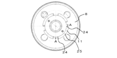
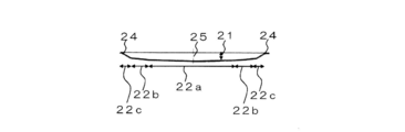
- FIG. 2 is a cross-sectional view taken along line AA of the front shell in FIG.
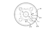
- FIG. 5 is a sectional view taken along line BB in FIG. 4.
- FIG. 2 is a tie rod type in which a master cylinder MC is fixed to a booster shell 2 by a tie rod bolt 3.
- the illustrated tie rod type negative pressure booster 1 includes a booster shell 2, a power piston 4, an input rod 5, an output rod 6, a return spring 7 for returning the power piston 4, and two tie rod bolts 3. It is configured in combination.
- the booster shell 2 is composed of a front shell 8 and a rear shell 9.
- the front shell 8 has a suction port 10 connected to the air supply manifold of the car engine. Furthermore, it has the rib 11 formed by curving the front shell 8 toward the inner side in the axial direction by press working.
- the power piston 4 is formed by combining a partition member 14 including a pressure plate 12 and a diaphragm 13 and a valve piston 17 having a negative pressure valve 15 and an atmospheric valve 16 therein.
- the negative pressure valve 15 is disposed in a passage that connects the constant pressure chamber 18 and the variable pressure chamber 19 to open and close the passage.
- the atmospheric valve 16 is disposed in a passage that connects the variable pressure chamber 19 to the outside, and opens and closes the passage.
- the input rod 6 is inserted into the valve piston 17, and when the input rod 6 is pushed by a driver's brake operation, the valve body of the negative pressure valve 15 contacts the valve seat, the negative pressure valve 15 is closed, and the constant pressure chamber 18 is transformed. The communication of the chamber 19 is cut off.
- the valve body of the atmospheric valve 16 is separated from the valve seat, the atmospheric valve 16 is opened, and the atmosphere flows into the variable pressure chamber 19.
- tie rod bolts 3 are inserted in an airtight manner into tie rod holes 20 provided in the front shell 8 and the rear shell 9 and tie rod holes 20 provided in the pressure plate.
- the tie rod bolt 3 is arranged so as to be parallel to a straight line passing through the center of the booster shell 2, and the master cylinder MC is fixed to the booster shell 2 with the tie rod bolt 3 as a fastener.
- the tie rod bolt 3 is also used to fix the booster shell 2 to the vehicle body of the vehicle in combination with a mounting bolt (not shown) for fixing the rear shell 9.
- the rib 11 is formed in a substantially arc shape so as to intermittently extend by a predetermined length in the circumferential direction.
- the rib depth 21, which is the length in the axial direction of the booster shell 2 has a gradually changing portion 22 that gradually increases from the end 24 in the circumferential direction of the rib 11 toward the central portion 25.
- the gradual change portion 22 has three stages (the first gradual change portion 22a having an angle of 0 ° to 3 ° formed by the angle formed between the surface parallel to the radial direction of the front shell 8 and the gradual change portion of the rib 11).
- the gradual change portion 22 is shown as the second gradual change portion 22b of 3 ° to 6 ° and the third gradual change portion 22c) having an angle of 20 ° to 30 °.
- the inflection portion 23 when the inflection portion 23 (see FIG. 3) is switched from the wall surface 26 having a large change amount of the rib depth 21 shown in FIG. 5 to the bottom surface 27 having a small change amount of the rib depth.
- the extension ratio of the inflection portion 23 in the rib 11 caused by pressing the front shell 8 can be reduced.
- the elongation rate indicates the degree of thinning of a specific location (value obtained by dividing the average thickness of the front shell by the thickness of the specific location). Therefore, it is possible to reduce the thickness of the inflection portion 23 in the rib 11.
- operation can be improved.
- the front shell 8 can be formed by setting the rib depth 21 to be larger than the conventional one. Thereby, the intensity
- the rib depth 21 of the rib 11 is formed so as to gradually increase from the end portion 24 in the circumferential direction toward the center portion 25.
- the rib depth 21 increases smoothly as it goes toward the central portion 25 in the circumferential direction of the rib 11, for example, the AA cross-sectional view in FIG.
- the gradual change portion 22 may also be formed. Thereby, it is possible to preferably avoid the formation of the inflection portion having a large curvature in the rib 11, and the reduction in thickness of the rib 11 can be reduced, so that the strength and durability of the front shell 8 can be improved.
- 1 and 2 show an embodiment using a tie rod type booster as a preferred embodiment, but the embodiment can be similarly applied to other than the tie rod type booster, and the strength and durability of the front shell are improved. it can.
- the rib 11 has a substantially arc shape extending in the circumferential direction.
- the rib 11 is formed so as to have a non-arc shape in the circumferential direction. Also good.
Landscapes
- Engineering & Computer Science (AREA)
- Transportation (AREA)
- Mechanical Engineering (AREA)
- Braking Systems And Boosters (AREA)
Abstract
フロントシェル(8)とリヤシェル(9)によって構成されるブースタシェル(2)と、ブースタシェル(2)内を定圧室(18)と変圧室(19)に区画するダイヤフラム(13)と、定圧室(18)がフロントシェル(8)とダイヤフラム(13)との間に形成され、変圧室(19)がリヤシェル(9)とダイヤフラム(13)との間に形成されている負圧式倍力装置(1)である。フロントシェル(8)は、ブースタシェル(2)の軸方向内側に向けて曲成され、かつ周方向に所定の長さに断続して延びるリブ(11)を有し、該リブ(11)における軸方向内側の軸長であるリブ深さ(21)が、周方向の端部(24)から中心部(25)に向かうにつれて大きくなる徐変部(22)を有することから、成形性を低下させることなくフロントシェル(8)の強度及び耐久性を向上させることができる。
Description
この発明は、車両のブレーキ装置に採用される負圧式倍力装置に関する。
この種の負圧式倍力装置(以下、ブースタ)の一つとして、フロントシェルとリヤシェルとからなるハウジング内を前方の負圧室と後方の変圧室とに区画する可動隔壁に連結されたバルブボディが軸孔を備えていて、この軸孔内には、前記バルブボディに対して軸方向に進退可能で入力部材と一体的に移動するプランジャと、このプランジャの前記バルブボディに対する進退移動に応じて前記負圧室と前記変圧室間を連通・遮断する負圧弁および前記変圧室と大気間を連通・遮断する大気弁を備えた弁機構が組み込まれるとともに、前記プランジャの前端部と前記バルブボディの前端部が後面に係合可能なリアクション部材と、このリアクション部材の前面に後端部にて係合し前記バルブボディに対して軸方向に移動可能な出力部材が組付けられているものがあり、例えば、下記の特許文献1に記載されている。
上記した特許文献1に記載されているフロントシェルを図4に示す。図4のフロントシェルでは、フロントシェルをブースタの中心側に向かって湾曲させることにより形成されるリブを有している。また、図5は、リブの図4におけるB-B断面図を示す。このリブは、フロントシェルの周方向に略円弧状となるように延び、かつ軸方向長さである軸長(以下、リブ深さ)が、リブの周方向における端部間で均一になるように形成されている。このリブは、ブースタの作動時における負圧導入の際に生じるフロントシェルに加わる応力に対するフロントシェルの強度及び耐久性を向上させることに寄与している。したがって、フロントシェルにリブを形成することにより、フロントシェルの変形を防ぐことができる。
しかしながら、上記した特許文献1に記載されているブースタでは、リブ深さがリブの周方向における端部間で均一になるように形成されている。このリブにおける周方向の中心に向かうにつれて変化するリブ深さの変化量に着目すると、リブ深さの変化量が大きい壁面(リブのブースタの軸方向と垂直な軸線に近い面)からリブ深さが均一(リブのブースタの軸方向と平行な軸線に近い面)な底面に切り替わる変曲部(図5参照)が形成される。この変曲部では、他の箇所に比べて曲率が大きくなる。このため、例えば、プレス成型によりフロントシェルを形成する場合、上述した変曲部では、他の箇所に比べて延び率が高くなる。ここで、延び率とは、特定箇所の薄板化した度合いを示す(フロントシェルの平均板厚を特定箇所の板厚で除算した値)。これにより、上述した変曲部では、他の箇所より薄板化してしまうため、フロントシェルの成形性、強度及び耐久性の低下が懸念される。また、フロントシェルの強度及び耐久性の向上を図るためリブ深さをより大きくすることが検討されている。しかしながら、上述した変曲部の薄板化により、従来に比してリブ深さを大きく設定した場合には、フロントシェルの成形時にリブの変曲部において破損を生じる虞がある。
上記課題を解決するために、請求項1に記載の発明は、フロントシェルとリヤシェルによって構成されるブースタシェルと、フロントシェルとリヤシェルとの間に配設されブースタシェル内を定圧室と変圧室に区画するダイヤフラムと、定圧室がフロントシェルとダイヤフラムとの間に形成されていて負圧源に接続されるように構成され、変圧室がリヤシェルと前記ダイヤフラムとの間に形成されていて定圧室または大気に接続されている負圧式倍力装置であって、フロントシェルは、ブースタシェルの軸方向内側に向けて曲成され、かつ周方向に所定の長さに断続して延びるリブを有し、該リブにおける軸方向内側の軸長であるリブ深さが、周方向の端部から中心部に向かうにつれて大きくなる徐変部を有することを特徴とする。
請求項1の発明によれば、上述した曲率が大きい(例えば、R4以下)変曲部(図5参照)が形成されることを低減できる。これにより、例えば、フロントシェルをプレス成型する場合、上述したリブの変曲部を有する場合に比べて、上述したリブの変曲部が他の箇所に比べて薄板化することを低減することができるので、フロントシェルの強度及び耐久性を向上できる。さらに、上述したリブの変曲部における薄板化を低減できるので、リブ深さを従来よりも大きく設定してフロントシェルを形成できる。これにより、成形性を低下させることなくフロントシェルの強度及び耐久性を向上できる。
請求項2に記載の発明においては、請求項1に記載の発明において、徐変部は、ブースタシェルの周方向における端部から中心部に向うにつれて、リブ深さが滑らかに大きくなることを特徴とする。
請求項2の発明によれば、リブ深さがリブの周方向における端部から中心部に向うにつれて滑らかに大きくなるため、上述した曲率が大きい変曲部が形成されることをより好適に低減できる。このため、例えば、フロントシェルのプレス成型する場合、上述したリブの変曲部が他の箇所に比べて薄板化することをより低減することができる。これにより、フロントシェルの強度及び耐久性をより向上させることができる。
以下、本発明の実施形態を図1~図3により具体的に説明するが、本発明はその趣旨を超えない限り、以下の実施形態によって限定されるものではない。
図1及び図2に示した負圧式倍力装置(ブースタ)1は、ブースタシェル2に対するマスタシリンダMCの固定をタイロッドボルト3によって行うタイロッド型である。
図示のタイロッド型負圧式倍力装置1は、ブースタシェル2と、パワーピストン4と、入力ロッド5と、出力ロッド6と、パワーピストン4を復帰させるリターンスプリング7と、2本のタイロッドボルト3を組み合わせて構成されている。
ブースタシェル2は、フロントシェル8とリヤシェル9とからなる。フロントシェル8は、車のエンジンの給気マニホールドに接続される吸引ポート10を有する。さらに、プレス加工にてフロントシェル8を軸方向内側に向けて湾曲させて形成されるリブ11を有する。
パワーピストン4は、プレッシャプレート12とダイヤフラム13とからなる隔壁部材14と、内部に負圧弁15と大気弁16とを備えたバルブピストン17を組み合わせてなる。
負圧弁15は、定圧室18と変圧室19を連通させる通路に配置されてその通路を開閉する。また、大気弁16は、変圧室19を外部につなぐ通路に配置されてその通路を開閉する。
入力ロッド6はバルブピストン17に挿入されており、運転者のブレーキ操作によってその入力ロッド6が押し込まれると負圧弁15の弁体が弁シートに接して負圧弁15が閉じ、定圧室18と変圧室19の連通が断たれる。
また、入力ロッド6の更なる押し込みによって、大気弁16の弁体が弁シートから離れ、大気弁16が開いて変圧室19に大気が流入する。
これにより、定圧室18と変圧室19に圧力差が生じ、その圧力差を受けたパワーピストン4が推進し、その推力(ブレーキ操作力に応じて増幅された力)が出力ロッド6を介してマスタシリンダMCに伝わってマスタシリンダMCが作動する。かかる作動メカニズムは、従来品の負圧式倍力装置と同じである。
タイロッドボルト3は、フロントシェル8とリヤシェル9にそれぞれ設けられたタイロッド孔20と、プレッシャプレートに設けられたタイロッド孔20に気密に挿通される。
このタイロッドボルト3は、ブースタシェル2の中心を通る直線と平行となるように配置されており、タイロッドボルト3を締結具にしてブースタシェル2にマスタシリンダMCが固定される。このタイロッドボルト3は、リヤシェル9を固定する取付けボルト(図示省略)と組み合わせてブースタシェル2を車両の車体に固定するのにも利用される。
上記した本実施形態における負圧式倍力装置1においては、リブ11が周方向において所定の長さだけ断続的に延びるように略円弧状に形成されている。また、ブースタシェル2の軸方向における長さであるリブ深さ21が、リブ11の周方向における端部24から中心部25に向うにしたがい徐々に大きくなる徐変部22を有している。
また、徐変部22は、フロントシェル8の径方向に平行な面とリブ11の徐変部とのなす角が3段階(なす角0°~3°の第1徐変部22a、なす角3°~6°の第2徐変部22b、なす角20°~30°の第3徐変部22c)となるような徐変部22を示している。
上記した負圧式倍力装置1では、図5に示すリブ深さ21の変化量が大きい壁面26からリブ深さの変化量が少ない底面27に切り替わる変曲部23(図3参照)を有する場合に比べて、例えば、フロントシェルをプレス成型する場合、フロントシェル8が押圧されることにより生じるリブ11における変曲部23の延び率を低減することができる。ここで、延び率とは、特定箇所の薄板化した度合いを示す(フロントシェルの平均板厚を特定箇所の板厚で除算した値)。したがって、リブ11における変曲部23の薄板化を低減できる。これにより、ブースタ作動時のときに生じるフロントシェル8を変形させようとする応力に対するフロントシェル8の強度及び耐久性を向上させることができる。さらに、上述したリブ11の変曲部23における薄板化を低減できるので、リブ深さ21を従来よりも大きく設定してフロントシェル8を形成できる。これにより、成形性を低下させることなくフロントシェルの強度及び耐久性を向上できる。
なお、図1及び図2では、リブ11のリブ深さ21が、周方向における端部24から中心部25に向うにしたがい徐々に大きく形成するように、フロントシェル8との周方向における平面とのなす角が3段階(徐変部22a、22b、22c)となるような実施形態を示した。しかしながら、リブ11の周方向における中心部25に向かうにしたがい、リブ深さ21が滑らかに大きくなるように、例えば、図2におけるA-A断面図が略円弧状または略楕円状となるような徐変部22でも形成してもよい。これにより、リブ11に曲率が大きい変曲部が形成されることを好適に避けることができ、リブ11における薄板化を低減できるため、フロントシェル8の強度及び耐久性を向上できる。
また、図1及び図2では、好ましい実施形態として、タイロッド型ブースタを用いた実施形態を示したが、タイロッド型ブースタ以外においても同様に実施することができ、フロントシェルの強度および耐久性を向上できる。
また、図1及び図2では、好ましい実施形態として、リブ11が周方向に延びる略円弧状の実施形態を示したが、リブ11の周方向における形状は非円弧状となるように形成してもよい。
1 負圧式倍力装置
2 ブースタシェル
3 タイロッド
4 パワーピストン
5 入力ロッド
6 出力ロッド
7 リターンスプリング
8 フロントシェル
9 リヤシェル
10 吸引ポート
11 リブ
12 プレッシャプレート
13 ダイヤフラム
14 隔壁部材
15 負圧弁
16 大気弁
17 バルブピストン
18 低圧室
19 変圧室
20 タイロッド孔
21 リブ深さ
22 徐変部
22a 第1徐変部
22b 第2徐変部
22c 第3徐変部
23 変曲部
24 端部
25 中心部
26 壁面
27 底面
MC マスタシリンダ
2 ブースタシェル
3 タイロッド
4 パワーピストン
5 入力ロッド
6 出力ロッド
7 リターンスプリング
8 フロントシェル
9 リヤシェル
10 吸引ポート
11 リブ
12 プレッシャプレート
13 ダイヤフラム
14 隔壁部材
15 負圧弁
16 大気弁
17 バルブピストン
18 低圧室
19 変圧室
20 タイロッド孔
21 リブ深さ
22 徐変部
22a 第1徐変部
22b 第2徐変部
22c 第3徐変部
23 変曲部
24 端部
25 中心部
26 壁面
27 底面
MC マスタシリンダ
Claims (2)
- フロントシェルとリヤシェルによって構成されるブースタシェルと、前記フロントシェルと前記リヤシェルとの間に配設され前記ブースタシェル内を定圧室と変圧室に区画するダイヤフラムと、
前記定圧室が前記フロントシェルと前記ダイヤフラムとの間に形成されていて負圧源に接続されるように構成され、前記変圧室が前記リヤシェルと前記ダイヤフラムとの間に形成されていて前記定圧室または大気に接続されている負圧式倍力装置であって、
前記フロントシェルは、前記ブースタシェルの軸方向内側に向けて曲成され、かつ周方向に所定の長さに断続して延びるリブを有し、該リブにおける前記軸方向内側の軸長であるリブ深さが、前記周方向の端部から中心部に向かうにつれて大きくなる徐変部を有することを特徴とする負圧式倍力装置。 - 前記徐変部は、前記ブースタシェルの周方向における端部から中心部に向うにつれて、前記リブ深さが滑らかに大きくなることを特徴とする請求項1に記載の負圧式倍力装置。
Applications Claiming Priority (2)
| Application Number | Priority Date | Filing Date | Title |
|---|---|---|---|
| JP2015015955A JP2016141168A (ja) | 2015-01-29 | 2015-01-29 | 負圧式倍力装置 |
| JP2015-015955 | 2015-01-29 |
Publications (1)
| Publication Number | Publication Date |
|---|---|
| WO2016121918A1 true WO2016121918A1 (ja) | 2016-08-04 |
Family
ID=56543522
Family Applications (1)
| Application Number | Title | Priority Date | Filing Date |
|---|---|---|---|
| PCT/JP2016/052626 Ceased WO2016121918A1 (ja) | 2015-01-29 | 2016-01-29 | 負圧式倍力装置 |
Country Status (2)
| Country | Link |
|---|---|
| JP (1) | JP2016141168A (ja) |
| WO (1) | WO2016121918A1 (ja) |
Cited By (1)
| Publication number | Priority date | Publication date | Assignee | Title |
|---|---|---|---|---|
| DE102016224939B4 (de) * | 2016-12-14 | 2026-05-07 | Aumovio Germany Gmbh | Bremskraftverstärker mit einer spannungsoptimierten Befestigungsstelle |
Citations (3)
| Publication number | Priority date | Publication date | Assignee | Title |
|---|---|---|---|---|
| JPH07205798A (ja) * | 1994-01-25 | 1995-08-08 | Nissin Kogyo Kk | 負圧ブースタにおけるブースタシェルの補強構造 |
| JP2007076437A (ja) * | 2005-09-13 | 2007-03-29 | Nissin Kogyo Co Ltd | 車両用負圧ブースタ |
| JP2010126039A (ja) * | 2008-11-28 | 2010-06-10 | Hitachi Automotive Systems Ltd | 気圧式倍力装置 |
-
2015
- 2015-01-29 JP JP2015015955A patent/JP2016141168A/ja active Pending
-
2016
- 2016-01-29 WO PCT/JP2016/052626 patent/WO2016121918A1/ja not_active Ceased
Patent Citations (3)
| Publication number | Priority date | Publication date | Assignee | Title |
|---|---|---|---|---|
| JPH07205798A (ja) * | 1994-01-25 | 1995-08-08 | Nissin Kogyo Kk | 負圧ブースタにおけるブースタシェルの補強構造 |
| JP2007076437A (ja) * | 2005-09-13 | 2007-03-29 | Nissin Kogyo Co Ltd | 車両用負圧ブースタ |
| JP2010126039A (ja) * | 2008-11-28 | 2010-06-10 | Hitachi Automotive Systems Ltd | 気圧式倍力装置 |
Cited By (1)
| Publication number | Priority date | Publication date | Assignee | Title |
|---|---|---|---|---|
| DE102016224939B4 (de) * | 2016-12-14 | 2026-05-07 | Aumovio Germany Gmbh | Bremskraftverstärker mit einer spannungsoptimierten Befestigungsstelle |
Also Published As
| Publication number | Publication date |
|---|---|
| JP2016141168A (ja) | 2016-08-08 |
Similar Documents
| Publication | Publication Date | Title |
|---|---|---|
| JP2018503040A (ja) | ディスクブレーキのための二重カップ形ピストン | |
| PH12019050147A1 (en) | A pressure piston cylinder with emergency braking | |
| JP5321803B2 (ja) | 気圧式倍力装置 | |
| JP2016141168A (ja) | 負圧式倍力装置 | |
| US8196505B2 (en) | Brake booster | |
| KR101461312B1 (ko) | 차량 브레이크 부스터용 키 | |
| JP6742781B2 (ja) | 負圧ブースタ用チェックバルブ | |
| US9045124B2 (en) | Vacuum brake booster | |
| JP5333726B2 (ja) | 気圧式倍力装置 | |
| KR100383580B1 (ko) | 차량용 텐덤 부스터의 센터플레이트 시일링장치 | |
| JP4206877B2 (ja) | 気圧式倍力装置 | |
| JP6326978B2 (ja) | 負圧式倍力装置 | |
| JP6260769B2 (ja) | 負圧式倍力装置 | |
| US9290168B2 (en) | Fixing structure for reinforcement plate and tie rod-type brake booster having the same | |
| JP4716100B2 (ja) | 気圧式倍力装置 | |
| US20130104728A1 (en) | Booster assembly for vehicle | |
| US7637200B2 (en) | Pneumatic brake booster | |
| US20130284012A1 (en) | Vacuum brake booster | |
| KR100931086B1 (ko) | 차량용 브레이크 부스터 | |
| JP6297318B2 (ja) | 気圧式倍力装置 | |
| US20060288859A1 (en) | Vacuum type brake booster | |
| KR100916397B1 (ko) | 차량용 브레이크 부스터 | |
| JP6387564B2 (ja) | 気圧式倍力装置 | |
| KR100774131B1 (ko) | 차량용 브레이크 부스터 | |
| KR101555664B1 (ko) | 자동차용 브레이크 부스터 |
Legal Events
| Date | Code | Title | Description |
|---|---|---|---|
| 121 | Ep: the epo has been informed by wipo that ep was designated in this application |
Ref document number: 16743521 Country of ref document: EP Kind code of ref document: A1 |
|
| NENP | Non-entry into the national phase |
Ref country code: DE |
|
| 122 | Ep: pct application non-entry in european phase |
Ref document number: 16743521 Country of ref document: EP Kind code of ref document: A1 |