WO2016121723A1 - 燃焼圧センサ - Google Patents
燃焼圧センサ Download PDFInfo
- Publication number
- WO2016121723A1 WO2016121723A1 PCT/JP2016/052092 JP2016052092W WO2016121723A1 WO 2016121723 A1 WO2016121723 A1 WO 2016121723A1 JP 2016052092 W JP2016052092 W JP 2016052092W WO 2016121723 A1 WO2016121723 A1 WO 2016121723A1
- Authority
- WO
- WIPO (PCT)
- Prior art keywords
- housing
- pressure sensor
- combustion pressure
- combustion engine
- fixing
- Prior art date
- Legal status (The legal status is an assumption and is not a legal conclusion. Google has not performed a legal analysis and makes no representation as to the accuracy of the status listed.)
- Ceased
Links
Images


Classifications
-
- F—MECHANICAL ENGINEERING; LIGHTING; HEATING; WEAPONS; BLASTING
- F02—COMBUSTION ENGINES; HOT-GAS OR COMBUSTION-PRODUCT ENGINE PLANTS
- F02D—CONTROLLING COMBUSTION ENGINES
- F02D35/00—Controlling engines, dependent on conditions exterior or interior to engines, not otherwise provided for
-
- G—PHYSICS
- G01—MEASURING; TESTING
- G01L—MEASURING FORCE, STRESS, TORQUE, WORK, MECHANICAL POWER, MECHANICAL EFFICIENCY, OR FLUID PRESSURE
- G01L23/00—Devices or apparatus for measuring or indicating or recording rapid changes, such as oscillations, in the pressure of steam, gas, or liquid; Indicators for determining work or energy of steam, internal-combustion, or other fluid-pressure engines from the condition of the working fluid
- G01L23/22—Devices or apparatus for measuring or indicating or recording rapid changes, such as oscillations, in the pressure of steam, gas, or liquid; Indicators for determining work or energy of steam, internal-combustion, or other fluid-pressure engines from the condition of the working fluid for detecting or indicating knocks in internal-combustion engines; Units comprising pressure-sensitive members combined with ignitors for firing internal-combustion engines
Definitions
- the present invention relates to a combustion pressure sensor for detecting a combustion pressure in a combustion chamber of an internal combustion engine.
- a combustion pressure sensor using a piezoelectric element is known as a sensor for detecting pressure in a high temperature and high pressure environment such as in a combustion chamber of an internal combustion engine (see, for example, Patent Document 1).
- Various detection methods are known for detecting pressure in a combustion pressure sensor using a piezoelectric element.
- the pressure (external force) to be detected is detected via a pressure transmission member.
- a method of detecting a charge signal that appears on the surface of a piezoelectric element by acting on the piezoelectric element is used.
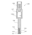
- FIG. 6 shows an outline of a combustion pressure sensor disclosed in Patent Document 1 as an example of this type of combustion pressure sensor.
- the illustrated combustion pressure sensor 100 includes a diaphragm 101 serving as a pressure receiving portion for pressure to be detected at a front end portion of a housing 106 formed in a cylindrical shape, and a piezoelectric element serving as a pressure detecting portion behind the diaphragm 101. 103 is disposed, and the pressure received by the diaphragm 101 is transmitted to the piezoelectric element 103 via the pressure transmitting member 102. Behind the piezoelectric element 103, an electrode portion 104 for transmitting charges generated from the piezoelectric element 103 is provided.
- a support member 105 fixed to the housing 106 is disposed behind the electrode portion 104, and the pressure transmission member 102, the piezoelectric element 103, and the electrode portion 104 are held in the housing 106 by the support member 105.
- the A circuit board 107 including a charge amplifier circuit that converts and amplifies the electric charge generated from the piezoelectric element 103 is disposed on the rear end side of the housing 106.
- the circuit board 107 includes the electrode unit 104 described above. Connected to.
- a connector 108 for outputting a pressure signal from the circuit board 107 to the outside is disposed at the rear end of the housing 106.
- this type of combustion pressure sensor 100 is attached to an internal combustion engine.
- a head portion 106a having a diameter larger than that of the front end side of the housing 106 is usually formed on the rear end side of the housing 106.
- the head portion 106a is used as a fixing portion for attaching to the internal combustion engine (see, for example, Patent Document 2).
- FIG. 7 shows an outline of the structure disclosed in Patent Document 2 as an example of this type of mounting structure.
- the combustion pressure sensor 100 is inserted into a housing opening 201 provided in the cylinder head of the internal combustion engine 200 so that the front end side of the housing 106 including the diaphragm 101 that is a pressure receiving portion is the combustion chamber side of the internal combustion engine 200.
- the head portion 106a of the combustion pressure sensor 100 covers the accommodation opening 201 provided in the cylinder head and is configured to come into contact with the surface of the cylinder head opposite to the combustion chamber.
- the fixing means 110 is fixed to the internal combustion engine 200 by screwing or the like, and the head portion 106a of the combustion pressure sensor 100 is fixed by the fixing means 110. It is fixed by being pressed against the cylinder head. Further, a seal member 109 that surrounds the outer peripheral surface of the combustion pressure sensor 100 is interposed between the outer peripheral surface on the distal end side of the housing 106 inserted into the accommodating opening 201 and the inner wall surface of the accommodating opening 201.
- the space between the outer peripheral surface on the front end side of the housing 106 and the inner wall surface of the housing opening 201 is sealed, so that leakage of combustion gas to the outside through the housing opening 201 from the combustion chamber of the internal combustion engine 200 is avoided. Is done.
- the conventional combustion pressure sensor described above has the following problems to be solved.
- an engine room where an internal combustion engine such as an automobile is disposed is generally limited space. Therefore, connection and disconnection of a cable to and from a connector of a combustion pressure sensor attached to the internal combustion engine is performed in a very narrow space.
- it is not possible to easily connect or remove the connector for example, it must be performed in a state where the connector connection portion cannot be visually observed.
- the twisting of the cable connected to the connector may cause cable disconnection or noise, so it is desirable to align the combustion pressure sensor connector in a specific direction, but the connector orientation and cable connection status should be Since it is difficult to confirm accurately by visual observation, it is not possible to sufficiently meet these requirements.
- the present invention aims to provide a combustion pressure sensor that solves such problems in the background art.
- a combustion pressure sensor is a combustion pressure sensor that detects a combustion pressure in a combustion chamber of an internal combustion engine in order to solve the above-described problem, and is a cylindrical sensor that can be inserted into a housing opening formed in the internal combustion engine.
- a sensor main body having a housing, a pressure receiving portion provided on the combustion chamber side of the housing, and a detection portion disposed in the housing behind the pressure receiving portion and detecting a pressure transmitted from the pressure receiving portion.
- a protrusion is provided on the housing for positioning the sensor main body in the rotational direction of the center axis of the sensor body when the housing is inserted into the housing opening, and the protrusion is fixed to the internal combustion engine.
- a fixing structure portion for fixing the sensor main body portion to the internal combustion engine is provided.
- the projecting portion can be fixed to the housing by being configured separately from the housing, and preferably, a different forming material, more desirably, to the housing. Can be formed by selecting a material having higher strength than the material for forming the housing.
- the projecting portion can be integrally formed by a coupling portion on one side and a fixing portion on the other side on the left and right sides, and the coupling portion can be fixed to the housing and the fixing portion can be fixed to the internal combustion engine.
- the coupling portion may be fixed to the housing through at least a fixing portion including welding or adhesion, or may be screwed into the coupling portion with a male screw portion formed on the outer peripheral surface of the housing.
- a female screw portion may be provided, and the female screw portion may be fixed to the housing by screwing into the male screw portion.
- the protrusion can be provided with an opening for passing a fixing screw for fixing the protrusion to the internal combustion engine.
- the opening is provided with a female screw formed on the inner peripheral surface, The internal diameter of this internal thread can be made larger than the internal diameter of the internal thread portion into which the fixing screw provided in the internal combustion engine is screwed.
- the protruding portion may be provided with a colored portion that exhibits a different color with respect to the surface of the housing or the rest of the surface of the protruding portion at least on a part of the surface.
- the combustion pressure sensor according to the present invention having such a configuration has the following remarkable effects.
- a cylindrical housing that can be inserted into a housing opening formed in an internal combustion engine, a pressure receiving portion provided on the combustion chamber side of the housing, and a pressure receiving portion disposed in the housing behind the pressure receiving portion.
- a sensor main body having a detector for detecting the pressure transmitted from the sensor, and positioning the sensor main body in the rotational direction of the central axis of the internal combustion engine when the housing is inserted into the housing opening.
- the connector of the combustion pressure sensor can be aligned in a specific direction, even if it is difficult to visually confirm the connector direction and cable connection state, the direction to lead out the cable is set to the optimal direction. In addition, it is possible to reduce variations in quality. As a result, it is possible to prevent twisting of the cable led out from the connector, and to contribute to elimination or reduction of the cause of cable disconnection and noise.
- the protruding portion may be formed of a different material with respect to the housing. Since it is possible to select a material with higher strength, the combustion pressure sensor can be securely fixed even when a stress in the bending direction is applied to the protruding portion, and the pressure measurement accuracy is impaired. Unnecessary adverse effects such as this can be avoided. In addition, since it is sufficient to add a separately prepared protrusion to the existing combustion pressure sensor, it can be implemented easily and at low cost.
- the protruding portion when forming the protruding portion, is integrally formed by a coupling portion on one side and a fixing portion on the other side on the left and right sides, and the coupling portion is fixed to the housing. If the coupling portion is fixed to the internal combustion engine, the coupling portion can protrude in the radial direction (perpendicular direction) from the housing. Therefore, when the coupling portion is fixed to the housing, at least welding or adhesion is included.
- An internal thread portion that is fixed to the housing by an adhering portion or is screwed to the external thread portion formed on the outer peripheral surface of the housing is provided at the coupling portion, and the internal thread portion is screwed to the external thread portion to be engaged with the housing.
- the combustion pressure sensor While being able to fix, it can implement reliably by selecting various forms, and it can implement easily by a simple process etc. Moreover, since the protrusion can be used as a knob (lever) integrated with the combustion pressure sensor, the combustion pressure sensor can be easily and quickly attached to and detached from the internal combustion engine.
- the projecting portion if the projecting portion is provided with an opening for passing a fixing screw for fixing the projecting portion to the internal combustion engine, the projecting portion can be obtained by using a fixing screw which is a general-purpose component.
- the internal combustion engine can be securely fixed and can be implemented easily and at low cost.
- the opening is provided with an internal thread formed on the inner peripheral surface, and the internal diameter of the internal thread is made larger than the internal diameter of the internal thread portion into which the fixing screw provided in the internal combustion engine is screwed.
- the combustion pressure sensor when the combustion pressure sensor is removed for maintenance or the like, even if the combustion pressure sensor (the housing) is difficult to be removed from the accommodation opening of the internal combustion engine due to adhesion of incomplete combustion products or the like, it is provided in the opening.
- the combustion pressure sensor can be easily removed by screwing a removal screw or the like into the female screw.
- the protrusion Since the visibility can be enhanced, for example, even when it is difficult to look dim, the protruding portion can be surely visually recognized, and the workability in attachment and detachment can be further enhanced.
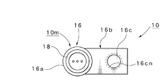
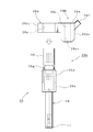
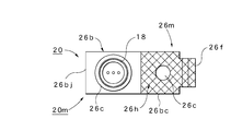
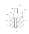
- a sectional front view of a combustion pressure sensor according to a first embodiment of the present invention A plan view of the combustion pressure sensor according to the first embodiment, Front sectional view showing a state in which the combustion pressure sensor according to the first embodiment is attached to the internal combustion engine, An exploded front view of a combustion pressure sensor according to a second embodiment of the present invention, A plan view of the combustion pressure sensor according to the second embodiment, A sectional front view of a combustion pressure sensor using a piezoelectric element according to the background art, A partially sectional front view showing a state in which the combustion pressure sensor is attached to an internal combustion engine,
- 10 Combustion pressure sensor
- 10m Sensor body
- 16 Housing
- 16b Protruding part
- 16m Fixed structure part
- 16bc Fixed part
- 16bj Coupling part
- 16c opening
- 16cn female screw formed on the inner peripheral surface of the opening
- 20 combustion pressure sensor
- 20m sensor main body part
- 26 housing
- 26b projecting part
- 26m fixing structure part
- 26bc fixing part
- 26bj coupling portion
- 26c opening
- 26d male screw portion formed on the outer peripheral surface of the housing
- 26e female screw portion provided on the coupling portion
- 26h colored portion
- 30 fixing screw
- 200 internal combustion engine
- 201 housing Opening
- 202 female thread part for screwing the fixing screw
- Jc fixing part
- FIGS. 1 is a cross-sectional front view of a combustion pressure sensor 10 according to a first embodiment of the present invention
- FIG. 2 is a plan view of the combustion pressure sensor 10
- FIG. 3 is a state in which the combustion pressure sensor 10 is attached to an internal combustion engine 200.
- the front sectional view shown is shown respectively.
- the combustion pressure sensor 10 includes a diaphragm 11 which is a pressure receiving portion for pressure to be detected at a front end portion of a cylindrical housing 16, and a rear side of the diaphragm 11. Is provided with a piezoelectric element 13 serving as a pressure detection unit. Thereby, the pressure received by the diaphragm 11 is transmitted to the piezoelectric element 13 via the pressure transmission unit 12. An electrode portion 14 for transmitting electric charges generated from the piezoelectric element 13 is disposed behind the piezoelectric element 13, and a support member 15 fixed to the housing 16 is disposed behind the electrode portion 14. To do. By the support member 15, the pressure transmission unit 12, the piezoelectric element 13, and the electrode unit 14 are held in the housing 16.
- a head portion 16a having a diameter larger than that of the front end side of the housing 16 is formed on the rear end side in the housing 16, and the electric charge generated from the piezoelectric element 13 is converted into a voltage inside the head portion 16a for amplification.
- a circuit board 17 including a charge amplifier circuit is disposed.
- the circuit board 17 is connected to the electrode unit 14 described above.
- a connector 18 for outputting a pressure signal from the circuit board 17 to the outside is disposed at the rear end of the housing 16.
- the sensor main body 10m is configured as described above.
- the head portion 16a is integrally provided with a protruding portion 16b that protrudes outward from the head portion 16a.
- the protrusion 16b according to the present embodiment is formed separately from the housing 16, that is, separately from the sensor body 10m.
- the protruding portion 16b is integrally formed by a coupling portion 16bj on one side and a fixing portion 16bc on the other side on the left and right.
- the overall shape of the protrusion 16b viewed from the front (FIG. 1) is an inverted L shape, and at least the tip of the coupling portion 16bj extending in the direction perpendicular to the axial direction of the housing 16 is welded or bonded. It fixes to the head part 16a with the adhering part Jc which contains.
- the housing 16 and the protrusion 16b are integrated.
- the fixing portion 16bc of the protruding portion 16b is provided with an opening 16c that is parallel to the axial direction of the housing 16 and through which the fixing screw 30 can pass.
- the opening 16c for passing the fixing screw 30 is provided in the protruding portion 16b, the protruding portion 16b and the internal combustion engine 200 can be reliably fixed by using the fixing screw 30 which is a general-purpose part, and easily In addition, there is an advantage that can be implemented at low cost.
- the opening 16c is provided with a female screw 16cn formed on the inner peripheral surface, and the internal combustion engine 200 is provided with a female screw portion 202 for screwing the distal end side of the fixing screw 30 (see FIG. 3).
- the inner diameter of the female screw 16cn is selected to be larger than the inner diameter of the female screw portion 202. That is, the inner diameter of the female screw 16 cn is selected to be larger than the outer diameter of the fixing screw 30 and smaller than the head of the fixing screw 30.
- the fixing structure 16m is constituted by the fixing part 16bc, the fixing screw 30, and the female screw part 202. If such a fixing structure 16m is provided, an incomplete combustion product or the like is generated when the combustion pressure sensor 10 is removed for maintenance or the like. Even if the combustion pressure sensor 10 (housing 16) is difficult to be removed from the accommodation opening 201 of the internal combustion engine 200 due to accumulation of the like, a removal screw or the like is screwed into the female screw 16cn provided in the opening 16c. There is an advantage that the combustion pressure sensor 10 can be easily removed by bringing the tip of a screw or the like into contact with the outer surface of the internal combustion engine 200 and further pressing it.
- a notch recess 16d having a diameter larger than that of the opening 16c is formed on the front end surface of the fixing portion 16bc (the surface contacting the internal combustion engine 200) in the protruding portion 16b.
- the fixing screw 30 is inserted into the opening 16 c and the snap ring 31 is attached to the ring groove of the fixing screw 30.
- the axial movement of the fixing screw 30 is restricted by the snap ring 31, so that the fixing screw 30 can be prevented from falling off from the opening 16 c and the workability of attaching and removing the combustion pressure sensor 10 can be improved. it can.
- the fixing screw 30 is screwed into the internal thread portion 202 of the internal combustion engine 200, the snap ring 31 is accommodated in the notch recess 16d.
- the protruding portion 16b is integrally formed by the one-side coupling portion 16bj and the other-side fixing portion 16bc on the left and right sides, and fixes the distal end of the coupling portion 16bj to the housing 16 and the fixing portion 16bc to the internal combustion engine 200. Since it is fixed, it can be easily implemented by simple processing or the like. Moreover, since the protrusion 16b can be used as a knob (lever) integrated with the combustion pressure sensor 10, there is an advantage that the combustion pressure sensor 10 can be easily and quickly attached to and detached from the internal combustion engine 200.
- the protruding portion 16b is protruded toward a specific direction selected (set) in advance with respect to the direction of the connector 18 in the central axis rotation direction of the combustion pressure sensor 10.
- a specific direction orientation
- the protruding portion 16b is integrally formed by the one-side coupling portion 16bj and the other-side fixing portion 16bc on the left and right sides, and the coupling portion 16bj is fixed to the housing 16 of the combustion pressure sensor 10 and the fixing portion.
- a large stress is applied to the protrusion 16b that fixes the combustion pressure sensor 10 from the combustion pressure sensor 10 side. Therefore, when the protrusion 16b is formed of a material having a relatively low strength, there is a possibility that a part of the protrusion 16b is bent. When the protrusion 16b is bent, the pressure to be detected is accurately measured. It produces a bug that cannot be done.
- a different forming material for the housing 16 preferably a material having higher strength, is selected and formed.
- a material having higher strength is selected and formed.
- the housing 16 uses “stainless steel material: SUS430”, “iron” is used for the protruding portion 16b. “Iron” is given as an example, but “stainless steel: SUS630” or the like can also be used.
- the housing 16 is preferably made of a SUS material in consideration of corrosion resistance, weldability, and the like.
- the projecting portion 16b formed separately is fixed to the housing 16, it is possible to select a different forming material for the housing 16 with respect to the housing 16, preferably a material having higher strength. Therefore, even if a stress in the bending direction is applied to the protruding portion 16b, the combustion pressure sensor 10 can be reliably fixed, and unnecessary adverse effects that impair the pressure measurement accuracy can be avoided. In addition, since it is sufficient to add a separately prepared protrusion 16b to the existing combustion pressure sensor 10, there is an advantage that it can be implemented easily and at low cost.
- a combustion pressure sensor 10 is prepared, and the combustion pressure sensor 10 is inserted into a housing opening 201 provided in a cylinder head of the internal combustion engine 200 so that the diaphragm 11 as a pressure receiving portion is on the combustion chamber side of the internal combustion engine 200. insert. Then, the head portion 16a of the combustion pressure sensor 10 is brought into contact with the outer surface of the cylinder head opposite to the combustion chamber, and is closed by covering the accommodation opening 201 provided in the cylinder head.
- the center position of the opening 16c provided in the integrally provided protruding portion 16b is made to coincide with the center position of the female thread portion 202 provided in the cylinder head of the internal combustion engine 200. Then, the distal end side of the fixing screw 30 is screwed into the female screw portion 202 to perform tightening. Thereby, the combustion pressure sensor 10 is fixed to the internal combustion engine 200. In this case, since the direction of the connector 18 in the combustion pressure sensor 10 is a specific direction, it is possible to enjoy the operational effects of selecting this specific direction.
- the connector 18 can be aligned in a specific direction, even if it is difficult to visually confirm the direction of the connector 18 or the connection state of the cable, the cable lead-out direction is the optimal direction, resulting in quality variations. Can be reduced. As a result, twisting of the cable led out from the connector 18 can be prevented, which can contribute to elimination or reduction of the cause of cable disconnection and noise. In addition, the work related to the connection and removal of the connector on the cable side from the combustion pressure sensor 10 can be easily performed.
- the seal member 19 that surrounds the outer circumferential surface of the combustion pressure sensor 10 is disposed between the outer circumferential surface on the distal end side of the housing 16 and the inner wall surface of the housing opening 201. Intervene. As a result, the space between the outer peripheral surface on the front end side of the housing 16 and the inner wall surface of the housing opening 201 is sealed, so that leakage of combustion gas to the outside through the housing opening 201 from the combustion chamber of the internal combustion engine 200 is avoided. Is done.
- combustion pressure sensor 10 can be easily removed from the internal combustion engine 200 by following the procedure opposite to the attachment method described above.
- a female screw 16cn formed on the inner peripheral surface is provided in the opening 16c, and an inner diameter of the female screw 16cn is set to the fixed screw 30 provided in the internal combustion engine 200. Is larger than the inner diameter of the female screw portion 202 to be screwed. Therefore, when the combustion pressure sensor 10 is fixed to the accommodation opening 201, a removal screw or the like may be screwed into the female screw 16cn provided in the opening 16c, and the rotation operation may be performed. Since the tip abuts on the outer surface of the internal combustion engine 200 and further presses the outer surface, the combustion pressure sensor 10 can be easily removed.
- FIG. 4 is an exploded front view of a combustion pressure sensor according to the second embodiment of the present invention
- FIG. 5 is a plan view of the combustion pressure sensor.
- the combustion pressure sensor 20 includes a diaphragm 11 that is a pressure receiving portion of a pressure to be detected at a front end portion of a housing 26 formed in a cylindrical shape, and is detected by the combustion pressure sensor 20 at a rear end portion of the housing 26.
- a connector 18 for outputting a pressure signal to the outside is provided.
- a head portion 26a having a diameter larger than that of the front end side of the housing 26 is formed on the rear end side of the housing 26, and a male screw portion 26d is provided on an upper portion of the outer peripheral surface of the head portion 26a.
- the sensor main body 20m is configured.
- the head portion 26a is provided with a protruding portion 26b that protrudes outward from the head portion 26a.
- the protrusion part 26b is formed separately from the head part 26a.
- the protruding portion 26b is integrally formed by a coupling portion 26bj on one side and a fixing portion 26bc on the other side on the left and right.
- the coupling portion 26bj is formed with a female screw portion 26e, and the female screw portion 26e is screwed into the male screw portion 26d of the head portion 26a, thereby integrating the protruding portion 26b with the sensor main body portion 20m.
- the protruding portion 26b is integrally formed by a coupling portion 26bj on one side and a fixing portion 26bc on the other side on the left and right sides, and the coupling portion 26bj is fixed to the housing 26, and the fixing portion 26bc is fixed to the internal combustion engine 200.
- the configuration is the same as that of the protrusion 16b of the first embodiment described above.
- the coupling portion 26bj (16bj) is fixed to the housing 26 (16)
- the coupling portion 26bj (16bj) is fixed to the housing 16 by the fixing portion Jc including at least welding or adhesion, or the coupling portion 16bj is fixed to the outer peripheral surface of the housing 26.
- the formation material of the housing 26 and the protrusion part 26b can be implemented similarly to the formation material of the housing 16 and the protrusion part 16b in 1st Embodiment.
- the protruding portion 26b is protruded toward a specific direction selected (set) in advance with respect to the direction of the connector 18 in the central axis rotation direction of the combustion pressure sensor 20.
- a specific direction orientation
- the pitch phases of the male screw portion 26d and the female screw portion 26e may be matched.
- the protrusion part 26b stops at a specific position and angle with respect to the head part 26a, and causes the protrusion part 26b to protrude in a specific direction with respect to the direction of the connector 18 in the central axis rotation direction of the combustion pressure sensor 20.
- the male screw portion 26d and the female screw portion 26e are screwed together, and the protruding portion 26b is located at a position in a specific direction with respect to the direction of the connector 18 in the rotation direction of the central axis of the combustion pressure sensor 20.
- the threaded portion between 26d and the female thread portion 26e may be fixed by an adhesive means or the like.
- the fixed structure portion 26m including the protruding portion 26b is provided. That is, an opening 26c similar to the above-described opening 16c is provided in the protruding portion 26b, and a female screw 26cn is formed on the inner peripheral surface of the opening 26c.
- the inner diameter of the female screw 26cn is selected to be larger than the inner diameter of the female screw portion 202 provided in the internal combustion engine 200. That is, the inner diameter of the female screw 26 cn is selected to be larger than the outer diameter of the fixing screw 30 and smaller than the head of the fixing screw 30.
- the protrusion 26b is integrally formed with a knob 26f that protrudes laterally from the protrusion 26b.
- the knob portion 26f applies a force for rotating the operation pressure lever 20 when the combustion pressure sensor 20 is removed from the internal combustion engine 200, that is, the combustion pressure sensor 20 including the housing 26 integrated with the protruding portion 26b. It can be used as a stop. Therefore, if this knob portion 26f is operated, it becomes easy to apply a force for rotating the combustion pressure sensor 20, so that the combustion pressure sensor 20 can be easily removed.
- At least part of the surface (lattice line in FIG. 5) of the protrusion 26b has a different color from the surface of the housing 26 or the rest of the surface of the protrusion 26b.
- a colored portion 26h is provided.
- the colored portion 26h can be implemented by applying a colored paint.
- identification marks such as numbers, letters, symbols, and the like may be attached to the surface of the protruding portion 26b by display means such as coloring or marking. This identification mark can be used for management of the combustion pressure sensor 20 or the like.
- 26 g indicates a notch provided in a part of the outer peripheral surface of the housing 26. Since a tool such as a spanner can be hooked on the notch 26g, the combustion pressure sensor 20 can be rotated by operating a tool such as a spanner hooked on the notch 26g. Thus, the notch 26g can be used as an auxiliary function for rotating the combustion pressure sensor 20, and the combustion pressure sensor 20 can be easily attached and detached.
- the components of the respective parts of the combustion pressure sensor 10 of the first embodiment and the combustion pressure sensor 20 of the second embodiment can be implemented in appropriate combination.
- the internal structure of the combustion pressure sensors 10 and 20 is not limited to the type using the illustrated piezoelectric element 13, but may be a piezoresistive element type or any other sensor type.
- 26m is a type in which the fixing screws 30 are inserted into the openings 16c and 26c provided in the projecting portions 16b and 26b, but may be implemented by other fixing means such as adhesion or welding.
- the relative positions of the connector 18 of the combustion pressure sensors 10 and 20 and the internal combustion engine 200 abut against the outer surfaces of the protrusions 16b and 26b and a part of the internal combustion engine 200, whereby the combustion pressure sensors 10 and 20
- the movement in the shaft rotation direction may be restricted (fixed).
- the housings 16 and 26 and the protrusions 16b and 26b of the combustion pressure sensors 10 and 20 are configured separately from each other and are combined (fixed), the housing 16 and the protrusions 16b and 26b are integrated.
- the portions 16b and 26b may be integrally formed of the same material.
- a configuration example is shown in which the head portions 16a and 26a are provided in the housings 16 and 26 of the combustion pressure sensors 10 and 20, and the accommodation openings 202 provided in the cylinder head in the internal combustion engine 200 are closed and covered by the head portions 16a and 26a.
- a configuration in which the head portions 16a and 26a are not provided in the housings 16 and 26 or a configuration in which the housing opening 202 is not covered by the head portions 16a and 26a may be employed.
- the accommodation opening 202 may be configured to be covered with a part of the protruding portions 16b and 26b.
- the female screws 16cn and 26cn are provided in the openings 16c and 26c into which the fixing screws 30 are inserted, and the combustion pressure sensors 10 and 20 can be detached using the female screws 16cn and 26cn, the structure example is shown.
- the internal threads 16cn and 26cn do not exclude the configuration provided other than the openings 16c and 26c.
- the combustion pressure sensor according to the present invention can be used in an attachment structure when attaching a combustion pressure sensor for measuring the pressure in the combustion chamber to various internal combustion engines.
Landscapes
- Engineering & Computer Science (AREA)
- Chemical & Material Sciences (AREA)
- Combustion & Propulsion (AREA)
- Mechanical Engineering (AREA)
- General Engineering & Computer Science (AREA)
- Physics & Mathematics (AREA)
- General Physics & Mathematics (AREA)
- Measuring Fluid Pressure (AREA)
Abstract
内燃機関の燃焼室内の燃焼圧を検出する燃焼圧センサであって、内燃機関に形成された収容開口に挿入可能な筒状のハウジングと、このハウジングの燃焼室側に設けた受圧部と、この受圧部の後方におけるハウジング内に配置し、受圧部から伝達される圧力を検出する検出部とを有するセンサ本体部を備え、ハウジングを内燃機関の収容開口に挿入した際に、内燃機関に対してセンサ本体部の中心軸回転方向の位置決めを行う突出部をハウジングに設けるとともに、当該突出部を内燃機関に固定することによりセンサ本体部を内燃機関に固定する固定構造部を設ける。
Description
本発明は、内燃機関の燃焼室内の燃焼圧を検出するための燃焼圧センサに関する。
従来、内燃機関の燃焼室内のような高温及び高圧の環境下で圧力を検知するセンサとしては、圧電素子を用いた燃焼圧センサが知られている(例えば、特許文献1参照)。また、圧電素子を用いた燃焼圧センサにおける圧力を検知する方法には、様々な検知方法が知られているが、一般的には、検知しようとする圧力(外力)を圧力伝達部材を介して圧電素子に作用させ、圧電素子の表面に表れる電荷信号を検知する方法が用いられている。
図6に、この種の燃焼圧センサの一例として、特許文献1に開示される燃焼圧センサの概要を示す。例示の燃焼圧センサ100は、筒状に形成されたハウジング106の前端部に、検出しようとする圧力の受圧部となるダイアフラム101を備えるとともに、このダイアフラム101の後方に圧力検出部である圧電素子103が配置され、ダイアフラム101の受けた圧力は、圧力伝達部材102を介して圧電素子103に伝達される。圧電素子103の後方には、圧電素子103から発生する電荷を伝送するための電極部104が設けられる。さらに、この電極部104の後方には、ハウジング106に固定された支持部材105が配置され、この支持部材105により、圧力伝達部材102,圧電素子103及び電極部104が、ハウジング106内で保持される。また、ハウジング106内の後端側には、圧電素子103から発生した電荷を電圧に変換し、増幅するチャージアンプ回路を含む回路基板107が配置され、この回路基板107は、上述した電極部104に接続される。そして、ハウジング106の後端部には、回路基板107からの圧力信号を外部へ出力するためのコネクタ108が配置される。
他方、この種の燃焼圧センサ100は内燃機関に取り付けられるが、この取り付けに際しては、通常、ハウジング106の後端側に、ハウジング106の先端側よりも径の大きいヘッド部106aが形成され、このヘッド部106aが内燃機関に取り付けるための固定部として利用される(例えば、特許文献2参照)。
図7に、この種の取り付け構造の一例として、特許文献2に開示される構造の概要を示す。燃焼圧センサ100は、受圧部であるダイアフラム101を含むハウジング106の先端側が内燃機関200の燃焼室側となるよう内燃機関200のシリンダヘッドに設けられた収容開口201に挿入される。このとき燃焼圧センサ100のヘッド部106aは、シリンダヘッドに設けられた収容開口201を覆い、シリンダヘッドの燃焼室と反対側の面に当接するよう構成される。そして、燃焼圧センサ100を内燃機関200に固定する際には、例えば、固定手段110が、ねじ止め等により内燃機関200に固定され、この固定手段110により、燃焼圧センサ100のヘッド部106aがシリンダヘッドに押し付けられることにより固定される。また、収容開口201に挿入されたハウジング106の先端側における外周面と当該収容開口201の内壁面間には、燃焼圧センサ100の外周面を包囲するシール部材109が介在される。これにより、ハウジング106の先端側における外周面と当該収容開口201の内壁面間がシールされるため、内燃機関200の燃焼室から収容開口201を通した、外部への燃焼ガスの漏れ出しが回避される。
しかし、上述した従来の燃焼圧センサは、次のような解決すべき課題も存在した。即ち、自動車等の内燃機関が配置されたエンジンルームは、一般に限られた空間になっているため、内燃機関に取り付けられた燃焼圧センサのコネクタに対するケーブルの接続や取り外しは、非常に狭い空間での作業が強いられるとともに、配置状況等によっては、コネクタの接続部を目視できない状態で実施しなければならないなど、コネクタの接続や取り外しの作業を容易に行うことができない。
また、コネクタに接続されるケーブルのねじれは、ケーブルの断線やノイズの発生原因にもなるため、燃焼圧センサのコネクタは特定の向きに揃えることが望ましいが、コネクタの向きやケーブルの接続状態を目視により正確に確認しにくいことから、これらの要請に対しても十分に応えることができない。
本発明はこのような背景技術に存在する課題を解決した燃焼圧センサの提供を目的とするものである。
本発明に係る燃焼圧センサは、上述した課題を解決するため、内燃機関の燃焼室内の燃焼圧を検出する燃焼圧センサであって、内燃機関に形成された収容開口に挿入可能な筒状のハウジングと、前記ハウジングの燃焼室側に設けた受圧部と、前記受圧部の後方における前記ハウジング内に配置し、前記受圧部から伝達される圧力を検出する検出部とを有するセンサ本体部を備え、前記ハウジングを前記収容開口に挿入した際に、前記内燃機関に対して前記センサ本体部の中心軸回転方向の位置決めを行う突出部を前記ハウジングに設けるとともに、前記突出部を前記内燃機関に固定することにより前記センサ本体部を前記内燃機関に固定する固定構造部を設けてなることを特徴とする。
この場合、好適な実施の態様により、前記突出部は、前記ハウジングに対して別体に構成することにより前記ハウジングに固定することができ、望ましくは、前記ハウジングに対して異なる形成材料、より望ましくは、前記ハウジングの形成材料よりも強度の高い材料を選定して形成できる。また、前記突出部は、左右における一方側の結合部及び他方側の固定部により一体形成し、前記結合部を前記ハウジングに固定するとともに、前記固定部を前記内燃機関に固定することができ、この際、前記結合部を、少なくとも溶接又は接着を含む固着部を介して前記ハウジングに固定してもよいし、或いは、前記結合部に、前記ハウジングの外周面に形成した雄ねじ部に螺合する雌ねじ部を設け、この雌ねじ部を前記雄ねじ部に螺合することにより前記ハウジングに固定してもよい。さらに、前記突出部には、当該突出部を前記内燃機関に固定する固定ねじを通すための開口を設けることができ、この際、この開口には、内周面に形成した雌ねじを設けるとともに、この雌ねじの内径は、前記内燃機関に設けた前記固定ねじを螺合する雌ねじ部の内径よりも大きくすることができる。加えて、前記突出部には、少なくとも表面の一部に、前記ハウジングの表面又は当該突出部の表面の残部に対して異なる色を呈する着色部を設けることもできる。
このような構成を有する本発明に係る燃焼圧センサによれば、次のような顕著な効果を奏する。
(1) 内燃機関に形成された収容開口に挿入可能な筒状のハウジングと、前記ハウジングの燃焼室側に設けた受圧部と、前記受圧部の後方における前記ハウジング内に配置し、前記受圧部から伝達される圧力を検出する検出部とを有するセンサ本体部を備え、前記ハウジングを前記収容開口に挿入した際に、前記内燃機関に対して前記センサ本体部の中心軸回転方向の位置決めを行う突出部を前記ハウジングに設けるとともに、前記突出部を前記内燃機関に固定することにより前記センサ本体部を前記内燃機関に固定する固定構造部を設けてなるため、燃焼圧センサを内燃機関に取り付ける際には、ケーブルを接続するコネクタの向きを特定の向きに揃えることができる。したがって、燃焼圧センサに対するケーブル側のコネクタの接続及び取り外しに係わる作業を容易に行うことができる。
(2) 燃焼圧センサのコネクタを特定の向きに揃えることができるため、コネクタの向きやケーブルの接続状態を目視により確認しにくい場合であっても、ケーブルを導出する向きを最適な向きに設定できるとともに、品質上のバラツキを低減できる。この結果、コネクタから導出されるケーブルのねじれを防止でき、ケーブルの断線やノイズの発生原因の解消又は低減に寄与できる。
(3) 好適な態様により、前記突出部を、前記ハウジングに対して別体に構成することにより前記ハウジングに固定するようにすれば、前記突出部には当該ハウジングに対して異なる形成材料、望ましく、より強度の高い材料を選定可能になるため、前記突出部に対して撓み方向の応力が付加される場合であっても燃焼圧センサを確実に固定することができ、圧力の測定精度を損なうような無用な悪影響を回避できる。加えて、既存の燃焼圧センサに対して別途用意した突出部を追加すれば足りるため、容易かつ低コストに実施することができる。
(4) 好適な態様により、前記突出部を形成するに際し、左右における一方側の結合部及び他方側の固定部により一体形成し、前記結合部を前記ハウジングに固定するとともに、前記固定部を前記内燃機関に固定するようにすれば、前記結合部は前記ハウジングから放射方向(軸直角方向)へ突出可能になるため、前記結合部を前記ハウジングに固定する際には、少なくとも溶接又は接着を含む固着部により前記ハウジングに固定したり、或いは前記結合部に前記ハウジングの外周面に形成した雄ねじ部に螺合する雌ねじ部を設け、この雌ねじ部を前記雄ねじ部に螺合することにより前記ハウジングに固定することができるなど、各種形態を選択することにより確実に実施できるとともに、簡易な加工等により容易に実施できる。しかも、前記突出部は燃焼圧センサに一体化したツマミ(レバー)として利用できるため、内燃機関に対する燃焼圧センサの取付け及び取外しを容易かつ迅速に行うことができる。
(5) 好適な態様により、前記突出部に、当該突出部を前記内燃機関に固定する固定ねじを通すための開口を設ければ、汎用部品である固定ねじを使用することにより、前記突出部と前記内燃機関を確実に固定できるとともに、容易かつ低コストに実施できる。
(6) 好適な態様により、前記開口に、内周面に形成した雌ねじを設けるとともに、この雌ねじの内径を、前記内燃機関に設けた前記固定ねじを螺合する雌ねじ部の内径よりも大きくすれば、メンテナンス等により前記燃焼圧センサを取り外す際に、不完全燃焼生成物等の付着により燃焼圧センサ(前記ハウジング)が前記内燃機関の収容開口から抜けにくい場合であっても、前記開口に設けた雌ねじに、取り外し用ねじ等を螺合することにより、前記燃焼圧センサを容易に取り外すことができる。
(7) 好適な態様により、前記突出部における、少なくとも表面の一部に、前記ハウジングの表面又は当該突出部の表面の残部に対して異なる色を呈する着色部を設ければ、前記突出部の視認性を高めることができるため、例えば、薄暗く見えにくいような場合であっても前記突出部を確実に視認し、取り付け及び取り外し等における作業性をより高めることができる。
10:燃焼圧センサ,10m:センサ本体部,11 ダイアフラム(受圧部),13:検出部(圧電素子),16:ハウジング,16b:突出部,16m:固定構造部,16bc:固定部,16bj:結合部,16c:開口,16cn:開口の内周面に形成した雌ねじ,20:燃焼圧センサ,20m:センサ本体部,26:ハウジング,26b:突出部,26m:固定構造部,26bc:固定部,26bj:結合部,26c:開口,26d:ハウジングの外周面に形成した雄ねじ部,26e:結合部に設けた雌ねじ部,26h:着色部,30:固定ねじ,200:内燃機関,201:収容開口,202:固定ねじを螺合する雌ねじ部,Jc:固着部
次に、本発明に係る最良実施形態(第1実施形態,第2実施形態)を挙げ、図面に基づき詳細に説明する。
まず、第1実施形態に係る燃焼圧センサ10の構成について、図1~図3を参照して説明する。図1は本発明の第1実施形態に係る燃焼圧センサ10の断面正面図、図2はこの燃焼圧センサ10の平面図、図3はこの燃焼圧センサ10を内燃機関200に取り付けた状態を示す正面断面図をそれぞれ示す。
燃焼圧センサ10は、図1及び図2に示すように、筒状に形成されたハウジング16の前端部に、検出しようとする圧力の受圧部であるダイアフラム11を備えるとともに、このダイアフラム11の後方には、圧力の検出部である圧電素子13を配設する。これにより、ダイアフラム11の受けた圧力は、圧力伝達部12を介して圧電素子13に伝達される。圧電素子13の後方には、圧電素子13から発生する電荷を伝送する電極部14を配設するとともに、さらに、この電極部14の後方には、ハウジング16に固定された支持部材15を配設する。この支持部材15により、圧力伝達部12,圧電素子13及び電極部14が、ハウジング16内で保持される。また、ハウジング16内の後端側には、ハウジング16の先端側より径が大きいヘッド部16aを形成し、このヘッド部16aの内部に、圧電素子13から発生した電荷を電圧に変換し、増幅するチャージアンプ回路を含む回路基板17を配設する。この回路基板17は、上述した電極部14に接続する。さらに、ハウジング16の後端部には、回路基板17からの圧力信号を外部へ出力するためのコネクタ18を配設する。以上によりセンサ本体部10mが構成される。
一方、ヘッド部16aには、このヘッド部16aから外方に突出する突出部16bを一体に設ける。本実施形態に係る突出部16bは、ハウジング16に対して別体、即ち、センサ本体部10mに対して別体に形成する。突出部16bは、図1に示すように、左右における一方側の結合部16bj及び他方側の固定部16bcにより一体形成する。これにより、突出部16bの正面(図1)から見た全体形状は、逆L形となり、ハウジング16の軸方向に対して直角方向に延出する結合部16bjの先端は、少なくとも溶接又は接着を含む固着部Jcによりヘッド部16aに固定する。この結果、ハウジング16と突出部16bは一体化される。
また、突出部16bの固定部16bcには、図3に示すように、ハウジング16の軸方向平行に沿い、かつ固定ねじ30を通すことができる開口16cを設ける。このように、突出部16bに固定ねじ30を通すための開口16cを設ければ、汎用部品である固定ねじ30を使用することにより、突出部16bと内燃機関200を確実に固定できるとともに、容易かつ低コストに実施できる利点がある。さらに、開口16cには、内周面に形成した雌ねじ16cnを設けるとともに、内燃機関200には、固定ねじ30の先端側を螺合する雌ねじ部202を設ける(図3参照)。この場合、雌ねじ16cnの内径は、雌ねじ部202の内径よりも大きく選定する。即ち、雌ねじ16cnの内径は、固定ねじ30の外径より大きく、かつ固定ねじ30の頭部よりも小さくなるように選定する。
固定部16bc,固定ねじ30及び雌ねじ部202により固定構造部16mが構成され、このような固定構造部16mを設ければ、メンテナンス等により燃焼圧センサ10を取り外す際に、不完全燃焼生成物等の堆積等により燃焼圧センサ10(ハウジング16)が内燃機関200の収容開口201から抜けにくい場合であっても、開口16cに設けた雌ねじ16cnに、取り外し用ねじ等を螺合させ、この取り外し用ねじ等の先端を内燃機関200の外面に当接させるとともに、更に押圧することにより、燃焼圧センサ10を容易に取り外すことができる利点がある。
なお、突出部16bにおける固定部16bcの先端面(内燃機関200に当接する面)には、開口16cよりも大径となる切欠凹部16dを形成するとともに、固定ねじ30の下部には、周方向に沿ったリング溝を形成する。そして、組付時には、開口16cに固定ねじ30を挿入するとともに、固定ねじ30のリング溝にスナップリング31を装着する。これにより、固定ねじ30の軸方向移動はスナップリング31により規制され、開口16cからの固定ねじ30の脱落を防止できるとともに、さらに、燃焼圧センサ10の取り付け及び取り外しの作業性を向上させることができる。また、固定ねじ30を内燃機関200の雌ねじ部202に螺合した際には、スナップリング31が切欠凹部16dに収容される。
このように、突出部16bは、左右における一方側の結合部16bj及び他方側の固定部16bcにより一体形成し、結合部16bjの先端をハウジング16に固定するとともに、固定部16bcを内燃機関200に固定するようにしたため、簡易な加工等により容易に実施できる。しかも、突出部16bは燃焼圧センサ10に一体化したツマミ(レバー)として利用できるため、内燃機関200に対する燃焼圧センサ10の取り付け及び取り外しを容易かつ迅速に行うことができる利点がある。
また、突出部16bは、燃焼圧センサ10の中心軸回転方向のコネクタ18の向きに対し、予め選定(設定)した特定の方向に向けて突出させる。特定の方向(向き)としては、コネクタ18にケーブル側のコネクタを接続した際に、当該ケーブルの引き回し位置において、ケーブルのねじれを防止し、ケーブルの断線やノイズの発生原因の解消又は低減に寄与できる方向であって、望ましくは、コネクタ18にケーブル側のコネクタを接続する際に、当該コネクタの接続及び取り外しに係わる作業を容易に行うことができる方向を選定する。
ところで、突出部16bは、上述したように、左右における一方側の結合部16bj及び他方側の固定部16bcにより一体形成し、結合部16bjを燃焼圧センサ10のハウジング16に固定するとともに、固定部16bcを内燃機関200に固定するため、燃焼圧センサ10を固定する突出部16bには、燃焼圧センサ10側から大きな応力が付加されることになる。したがって、突出部16bを比較的強度の低い材料で形成した場合、突出部16bの一部が撓む虞れがあり、突出部16bが撓んだ場合には、検出すべき圧力を正確に測定できない不具合を生じる。
このため、突出部16bを形成するに際しては、ハウジング16に対して異なる形成材料、望ましくは、より強度の高い材料を選定して形成する。例示の場合、ハウジング16は「ステンレス鋼材:SUS430」を用いているため、突出部16bには、「鉄」を用いた。「鉄」は一例として挙げたが、その他、「ステンレス鋼材:SUS630」等も用いることができる。なお、ハウジング16には、耐食性及び溶接性等を考慮してSUS材を用いることが好ましい。
このように、別体に形成した突出部16bをハウジング16に固定するようにすれば、突出部16bには当該ハウジング16に対して異なる形成材料、望ましく、より強度の高い材料を選定可能になるため、突出部16bに対して撓み方向の応力が付加される場合であっても燃焼圧センサ10を確実に固定することができ、圧力の測定精度を損なうような無用な悪影響を回避できる。加えて、既存の燃焼圧センサ10に対して別途用意した突出部16bを追加すれば足りるため、容易かつ低コストに実施できる利点がある。
次に、第1実施形態に係る燃焼圧センサ10の内燃機関200に対する取り付け及び取り外し方法について、図3を参照して説明する。
最初に、内燃機関200に対する燃焼圧センサ10の取り付け方法について説明する。まず、燃焼圧センサ10を用意し、この燃焼圧センサ10を、受圧部であるダイアフラム11が内燃機関200の燃焼室側となるようして、内燃機関200のシリンダヘッドに設けた収容開口201に挿入する。そして、燃焼圧センサ10のヘッド部16aをシリンダヘッドの燃焼室と反対側の外面に当接させ、シリンダヘッドに設けた収容開口201を覆っうことにより閉塞する。
また、一体に備える突出部16bに設けた開口16cの中心位置を、内燃機関200のシリンダヘッドに設けた雌ねじ部202の中心位置に一致させる。そして、固定ねじ30の先端側を雌ねじ部202に螺合させて締め付けを行う。これにより、燃焼圧センサ10は内燃機関200に固定される。この場合、燃焼圧センサ10におけるコネクタ18の向きは特定の向きとなるため、この特定の向きを選定したことによる作用効果を享受できる。即ち、コネクタ18を特定の向きに揃えることができるため、コネクタ18の向きやケーブルの接続状態を目視により確認しにくい場合であっても、ケーブルの導出方向は最適な向きとなり、品質上のバラツキを低減できる。この結果、コネクタ18から導出されるケーブルのねじれを防止でき、ケーブルの断線やノイズの発生原因の解消又は低減に寄与できる。しかも、燃焼圧センサ10に対するケーブル側のコネクタの接続及び取り外しに係わる作業を容易に行うことができる。
なお、燃焼圧センサ10を収容開口201に挿入する際には、ハウジング16の先端側における外周面と当該収容開口201の内壁面間に、燃焼圧センサ10の外周面を包囲するシール部材19を介在させる。これにより、ハウジング16の先端側における外周面と当該収容開口201の内壁面間がシールされるため、内燃機関200の燃焼室から収容開口201を通した、外部への燃焼ガスの漏れ出しが回避される。
次に、内燃機関200からの燃焼圧センサ10の取り外し方法について説明する。通常は、上述した取り付け方法と逆の手順に従えば、内燃機関200から燃焼圧センサ10を容易に取り外すことができる。
ところで、内燃機関200に、燃焼圧センサ10を取り付けて使用した場合、使用の経過とともに、収容開口201と燃焼圧センサ10の隙間に燃料やオイルの不完全燃焼生成物が堆積し、燃焼圧センサ10が収容開口201に固着することがあり、この場合、燃焼圧センサ10の取り外しは非常に困難になる。
このため、本実施形態に係る燃焼圧センサ10では、この対策として、開口16cに、内周面に形成した雌ねじ16cnを設けるとともに、この雌ねじ16cnの内径を、内燃機関200に設けた固定ねじ30を螺合する雌ねじ部202の内径よりも大きくした。したがって、燃焼圧センサ10が収容開口201に固着した場合には、開口16cに設けた雌ねじ16cnに対して取り外し用ねじ等を螺合させ、回し操作すればよく、これにより、取り外し用ねじ等の先端は、内燃機関200の外面に当接するとともに、更に外面を押圧するため、燃焼圧センサ10を容易に取り外すことができる。
次に、第2実施形態に係る燃焼圧センサ20について、図4及び図5を参照して説明する。図4は本発明の第2実施形態に係る燃焼圧センサの分解正面図、図5はこの燃焼圧センサの平面図をそれぞれ示す。
なお、第2実施形態では、特に、第1実施形態に対して相違する点を詳述し、燃焼圧センサ20の内部構造等の同一部分についての説明は省略する。このため、図4及び図5において、第1実施形態と同一部分に対しては同一符号を付し、重複説明を適宜省略するとともに、第1実施形態に対しては異なる形状や機能を有する部分については新たな符号を付して説明する。
燃焼圧センサ20は、筒状に形成されたハウジング26の前端部に、検出しようとする圧力の受圧部であるダイアフラム11を備えるとともに、ハウジング26の後端部には燃焼圧センサ20により検出した圧力信号を外部へ出力するためのコネクタ18を備える。ハウジング26の後端側には、ハウジング26の先端側より径が大きいヘッド部26aを形成し、このヘッド部26aの外周面における上部には雄ねじ部26dを設ける。以上により、センサ本体部20mが構成される。
一方、ヘッド部26aには、このヘッド部26aから外方に突出する突出部26bを設ける。例示の場合、突出部26bはヘッド部26aに対して別体に形成する。突出部26bは、図4に示すように、左右における一方側の結合部26bj及び他方側の固定部26bcにより一体形成する。そして、結合部26bjには、雌ねじ部26eを形成し、この雌ねじ部26eをヘッド部26aの雄ねじ部26dに螺合することにより、センサ本体部20mに対して突出部26bを一体化させる。
突出部26bは、左右における一方側の結合部26bj及び他方側の固定部26bcにより一体形成し、結合部26bjをハウジング26に固定するとともに、固定部26bcを内燃機関200に固定するため、基本的な構成は、前述した第1実施形態の突出部16bと同じになる。このように、結合部26bj(16bj)をハウジング26(16)に固定するに際しては、少なくとも溶接又は接着を含む固着部Jcによりハウジング16に固定したり、或いは結合部16bjにハウジング26の外周面に形成した雄ねじ部26dに螺合する雌ねじ部26eを設け、この雌ねじ部26eを雄ねじ部26dに螺合することによりハウジング26に固定できるなど、各種形態を選択することにより確実に実施できる。なお、ハウジング26及び突出部26bの形成材料は、第1実施形態におけるハウジング16及び突出部16bの形成材料と同様に実施できる。
また、突出部26bは、燃焼圧センサ20の中心軸回転方向のコネクタ18の向きに対し、予め選定(設定)した特定の方向に向けて突出させる。特定の方向(向き)としては、コネクタ18にケーブル側のコネクタを接続した際に、当該ケーブルの引き回し位置において、ケーブルのねじれを防止し、ケーブルの断線やノイズの発生原因の解消又は低減に寄与できる方向であって、望ましくは、コネクタ18にケーブル側のコネクタを接続する際に、当該コネクタの接続及び取り外しに係わる作業を容易に行うことができる方向を選定する。
この場合、特定の方向(向き)に揃える方法としては、雄ねじ部26dと雌ねじ部26eのピッチの位相を一致させればよい。これにより、突出部26bは、ヘッド部26aに対して特定の位置及び角度で停止し、突出部26bを燃焼圧センサ20の中心軸回転方向のコネクタ18の向きに対して特定の方向に突出させることができる。その他の方法としては、雄ねじ部26dと雌ねじ部26eを螺合し、突出部26bを燃焼圧センサ20の中心軸回転方向のコネクタ18の向きに対して特定の方向になった位置で、雄ねじ部26dと雌ねじ部26eの螺合部分を接着手段等により固定してもよい。
さらに、第1実施形態における固定構造部16mと同様に、突出部26bを含む固定構造部26mを設ける。即ち、突出部26bに、前述した開口16cと同様の開口26cを設け、この開口26cの内周面に雌ねじ26cnを形成する。この雌ねじ26cnの内径は、内燃機関200に設ける雌ねじ部202の内径よりも大きく選定する。即ち、雌ねじ26cnの内径を、固定ねじ30の外径より大きく、かつ固定ねじ30の頭部よりも小さくなるように選定する。
一方、第2実施形態に係る突出部26bには、この突出部26bから側方へ突出するつまみ部26fを一体に形成する。これにより、つまみ部26fは、燃焼圧センサ20を内燃機関200から取り外すときの操作レバー、即ち、突出部26bと一体となったハウジング26を含む燃焼圧センサ20を軸回転させるための力の掛止部として利用可能となる。したがって、このつまみ部26fを操作すれば、燃焼圧センサ20を軸回転させるための力を作用させやすくなるため、燃焼圧センサ20の取り外し等を容易に行うことができる。
加えて、図4に示すように、突出部26bにおける、少なくとも表面の一部(図5中の格子線)には、ハウジング26の表面又は当該突出部26bの表面の残部に対して異なる色を呈する着色部26hを設ける。この着色部26hは着色塗料の塗布により実施可能である。これにより、突出部26bの視認性を高めることができるため、例えば、薄暗く見えにくいような場合であっても突出部26bを確実に視認し、取り付け及び取り外し等における作業性をより高めることができる。その他、突出部26bの表面に、着色又は刻印等の表示手段により、数字,文字,記号等の識別マークを付してもよい。この識別マークは燃焼圧センサ20の管理等に利用可能である。
なお、図4中、26gは、ハウジング26の外周面の一部に設けた切欠部を示す。この切欠部26gにはスパナ等の工具を掛止することができるため、この切欠部26gに掛止させたスパナ等の工具を操作することにより燃焼圧センサ20を軸回転させることができる。このように、切欠部26gは、燃焼圧センサ20を軸回転させるための補助機能として利用でき、燃焼圧センサ20の取り付け及び取り外しを容易に行うことができる。
以上、最良実施形態(第1実施形態及び第2実施形態)について詳細に説明したが、本発明は、このような実施形態に限定されるものではなく、細部の構成,形状,素材,数量,手法等において、本発明の要旨を逸脱しない範囲で、任意に変更,追加,削除することができる。
例えば、第1実施形態の燃焼圧センサ10と第2実施形態の燃焼圧センサ20の各部の構成要素は、適宜組み合わせて実施することができる。また、燃焼圧センサ10,20の内部構造は、例示した圧電素子13を利用したタイプに限定されるものではなく、ピエゾ抵抗素子タイプや他の任意のセンサタイプであってもよい。さらに、燃焼圧センサ10,20を内燃機関200に固定する固定構造部16m.26mは、一例として、突出部16b,26bに設けた開口16c,26cに固定ねじ30…を挿入するタイプを挙げたが、その他、接着や溶接等の固着手段により実施してもよい。
また、燃焼圧センサ10,20のコネクタ18と内燃機関200の相対的な位置は、突出部16b,26bの外面と内燃機関200の一部を突き当て、これにより、燃焼圧センサ10,20の軸回転方向の動きを規制(固定)してもよい。さらに、燃焼圧センサ10,20のハウジング16,26と突出部16b,26bは、それぞれ別体に構成し、結合(固定)することにより一体化した例を示したが、ハウジング16,26と突出部16b,26bを同一材料により一体形成してもよい。また、燃焼圧センサ10,20のハウジング16,26にヘッド部16a,26aを設け、このヘッド部16a,26aにより内燃機関200におけるシリンダヘッドに設けた収容開口202を閉塞して覆う構成例を示したが、ハウジング16,26にヘッド部16a,26aを設けない構成又はヘッド部16a,26aにより収容開口202を覆わない構成であってもよい。この場合、収容開口202を、突出部16b,26bの一部で覆う構成でもよい。さらに、固定ねじ30を挿入する開口16c,26cに雌ねじ16cn,26cnを設け、この雌ねじ16cn,26cnを利用して燃焼圧センサ10,20の取り外しを行える構造例を示したが、取り外しに利用する雌ねじ16cn,26cnは、開口16c,26c以外に設ける構成を排除するものではない。
本発明に係る燃焼圧センサは、燃焼室内の圧力を測定する燃焼圧センサを各種内燃機関に取り付ける際の取付構造に利用できる。
Claims (10)
- 内燃機関の燃焼室内の燃焼圧を検出する燃焼圧センサであって、内燃機関に形成された収容開口に挿入可能な筒状のハウジングと、前記ハウジングの燃焼室側に設けた受圧部と、前記受圧部の後方における前記ハウジング内に配置し、前記受圧部から伝達される圧力を検出する検出部とを有するセンサ本体部を備え、前記ハウジングを前記収容開口に挿入した際に、前記内燃機関に対して前記センサ本体部の中心軸回転方向の位置決めを行う突出部を前記ハウジングに設けるとともに、前記突出部を前記内燃機関に固定することにより前記センサ本体部を前記内燃機関に固定する固定構造部を設けてなることを特徴とする燃焼圧センサ。
- 前記突出部は、前記ハウジングに対して別体に構成することにより前記ハウジングに固定してなることを特徴とする請求項1記載の燃焼圧センサ。
- 前記突出部は、前記ハウジングに対して異なる材料により形成することを特徴とする請求項2記載の燃焼圧センサ。
- 前記突出部は、形成材料として、前記ハウジングの形成材料よりも強度の高い材料を選定することを特徴とする請求項3記載の燃焼圧センサ。
- 前記突出部は、左右における一方側の結合部及び他方側の固定部により一体形成し、前記結合部の先端側を前記ハウジングに固定するとともに、前記固定部を前記内燃機関に固定することを特徴とする請求項1記載の燃焼圧センサ。
- 前記突出部は、前記結合部の先端を、少なくとも溶接又は接着を含む固着部を介して、前記ハウジングに固定することを特徴とする請求項1~5のいずれかに記載の燃焼圧センサ。
- 前記突出部は、前記結合部の先端側に、前記ハウジングの外周面に形成した雄ねじ部に螺合する雌ねじ部を設け、この雌ねじ部を前記雄ねじ部に螺合することにより前記ハウジングに固定することを特徴とする請求項1~5のいずれかに記載の燃焼圧センサ。
- 前記突出部は、当該突出部を前記内燃機関に固定する固定ねじを通すための開口を有することを特徴とする請求項1又は5記載の燃焼圧センサ。
- 前記開口は、内周面に形成した雌ねじを有するとともに、この雌ねじの内径は、前記内燃機関に設けた前記固定ねじを螺合する雌ねじ部の内径よりも大きくすることを特徴とする請求項8に記載の燃焼圧センサ。
- 前記突出部は、少なくとも表面の一部に、前記ハウジングの表面又は当該突出部の表面の残部に対して異なる色を呈する着色部を設けてなることを特徴とする請求項1記載の燃焼圧センサ。
Priority Applications (1)
| Application Number | Priority Date | Filing Date | Title |
|---|---|---|---|
| JP2016572036A JP6779137B2 (ja) | 2015-01-29 | 2016-01-26 | 燃焼圧センサ |
Applications Claiming Priority (2)
| Application Number | Priority Date | Filing Date | Title |
|---|---|---|---|
| JP2015-014942 | 2015-01-29 | ||
| JP2015014942 | 2015-01-29 |
Publications (1)
| Publication Number | Publication Date |
|---|---|
| WO2016121723A1 true WO2016121723A1 (ja) | 2016-08-04 |
Family
ID=56543336
Family Applications (1)
| Application Number | Title | Priority Date | Filing Date |
|---|---|---|---|
| PCT/JP2016/052092 Ceased WO2016121723A1 (ja) | 2015-01-29 | 2016-01-26 | 燃焼圧センサ |
Country Status (2)
| Country | Link |
|---|---|
| JP (1) | JP6779137B2 (ja) |
| WO (1) | WO2016121723A1 (ja) |
Citations (3)
| Publication number | Priority date | Publication date | Assignee | Title |
|---|---|---|---|---|
| JPH02144663U (ja) * | 1989-05-12 | 1990-12-07 | ||
| JP2006161727A (ja) * | 2004-12-08 | 2006-06-22 | Mitsubishi Motors Corp | インジェクタの取付構造 |
| JP2010091563A (ja) * | 2008-10-07 | 2010-04-22 | Robert Bosch Gmbh | 燃焼室圧力センサ |
Family Cites Families (1)
| Publication number | Priority date | Publication date | Assignee | Title |
|---|---|---|---|---|
| JP2004349133A (ja) * | 2003-05-22 | 2004-12-09 | Denso Corp | 内燃機関用の点火装置及び,その取り付け構造 |
-
2016
- 2016-01-26 WO PCT/JP2016/052092 patent/WO2016121723A1/ja not_active Ceased
- 2016-01-26 JP JP2016572036A patent/JP6779137B2/ja not_active Expired - Fee Related
Patent Citations (3)
| Publication number | Priority date | Publication date | Assignee | Title |
|---|---|---|---|---|
| JPH02144663U (ja) * | 1989-05-12 | 1990-12-07 | ||
| JP2006161727A (ja) * | 2004-12-08 | 2006-06-22 | Mitsubishi Motors Corp | インジェクタの取付構造 |
| JP2010091563A (ja) * | 2008-10-07 | 2010-04-22 | Robert Bosch Gmbh | 燃焼室圧力センサ |
Also Published As
| Publication number | Publication date |
|---|---|
| JPWO2016121723A1 (ja) | 2017-11-30 |
| JP6779137B2 (ja) | 2020-11-04 |
Similar Documents
| Publication | Publication Date | Title |
|---|---|---|
| US7408122B2 (en) | Cable gland | |
| US11867327B2 (en) | Fluid-tight fitting | |
| US20050118853A1 (en) | Electrical connector | |
| JP6093323B2 (ja) | 物理量測定装置及びその製造方法 | |
| US7855551B2 (en) | Stick position sensor with removable cover for a sensor head | |
| US20100011870A1 (en) | Pressure Gauge | |
| US7426870B2 (en) | Torsional fixing device, especially for the housing of a measuring transducer | |
| US4825710A (en) | Enclosure for electrical sensor | |
| CN113263875B (zh) | 阀系统、轮胎参数监测系统和将轮胎参数监测系统安装到车辆轮辋上的方法 | |
| EP0453067B1 (en) | Rotational speed probe | |
| US10274388B2 (en) | Pressure sensor including sensor module having diaphragm and joint attached with the sensor module | |
| US20140340076A1 (en) | Sensor unit | |
| WO2016121723A1 (ja) | 燃焼圧センサ | |
| US4939406A (en) | Arrangement for fastening a housing | |
| JP2017198553A (ja) | 歪み検出センサ | |
| JP6127009B2 (ja) | 物理量測定装置 | |
| JP2017009029A (ja) | センサ付き軸受 | |
| JP5154847B2 (ja) | オイルチェックセンサ | |
| KR102359515B1 (ko) | 절연플러그용 절연캡 | |
| JP2006194751A (ja) | 電磁流量計 | |
| US20220220991A1 (en) | Screw connection system, method for screwing together reinforced long molded parts, and use of a screw connection system | |
| US20210396264A1 (en) | Pressure nut for cable or tube connections | |
| JP2008215583A (ja) | タンクの密封装置 | |
| EP3405668B1 (en) | Mounting arrangement and method for connecting a sensor | |
| EA044662B1 (ru) | Система завинчивания, способ завинчивания армированных длинных формованных частей, а также применение системы завинчивания |
Legal Events
| Date | Code | Title | Description |
|---|---|---|---|
| 121 | Ep: the epo has been informed by wipo that ep was designated in this application |
Ref document number: 16743326 Country of ref document: EP Kind code of ref document: A1 |
|
| ENP | Entry into the national phase |
Ref document number: 2016572036 Country of ref document: JP Kind code of ref document: A |
|
| NENP | Non-entry into the national phase |
Ref country code: DE |
|
| 122 | Ep: pct application non-entry in european phase |
Ref document number: 16743326 Country of ref document: EP Kind code of ref document: A1 |