WO2016120974A1 - 光源装置及びそれを利用した照明器具と車両用灯具 - Google Patents
光源装置及びそれを利用した照明器具と車両用灯具 Download PDFInfo
- Publication number
- WO2016120974A1 WO2016120974A1 PCT/JP2015/052040 JP2015052040W WO2016120974A1 WO 2016120974 A1 WO2016120974 A1 WO 2016120974A1 JP 2015052040 W JP2015052040 W JP 2015052040W WO 2016120974 A1 WO2016120974 A1 WO 2016120974A1
- Authority
- WO
- WIPO (PCT)
- Prior art keywords
- light source
- texture
- light
- source device
- shape
- Prior art date
Links
Images


Classifications
-
- F—MECHANICAL ENGINEERING; LIGHTING; HEATING; WEAPONS; BLASTING
- F21—LIGHTING
- F21S—NON-PORTABLE LIGHTING DEVICES; SYSTEMS THEREOF; VEHICLE LIGHTING DEVICES SPECIALLY ADAPTED FOR VEHICLE EXTERIORS
- F21S43/00—Signalling devices specially adapted for vehicle exteriors, e.g. brake lamps, direction indicator lights or reversing lights
- F21S43/20—Signalling devices specially adapted for vehicle exteriors, e.g. brake lamps, direction indicator lights or reversing lights characterised by refractors, transparent cover plates, light guides or filters
- F21S43/235—Light guides
- F21S43/247—Light guides with a single light source being coupled into the light guide
-
- F—MECHANICAL ENGINEERING; LIGHTING; HEATING; WEAPONS; BLASTING
- F21—LIGHTING
- F21S—NON-PORTABLE LIGHTING DEVICES; SYSTEMS THEREOF; VEHICLE LIGHTING DEVICES SPECIALLY ADAPTED FOR VEHICLE EXTERIORS
- F21S2/00—Systems of lighting devices, not provided for in main groups F21S4/00 - F21S10/00 or F21S19/00, e.g. of modular construction
-
- F—MECHANICAL ENGINEERING; LIGHTING; HEATING; WEAPONS; BLASTING
- F21—LIGHTING
- F21S—NON-PORTABLE LIGHTING DEVICES; SYSTEMS THEREOF; VEHICLE LIGHTING DEVICES SPECIALLY ADAPTED FOR VEHICLE EXTERIORS
- F21S43/00—Signalling devices specially adapted for vehicle exteriors, e.g. brake lamps, direction indicator lights or reversing lights
- F21S43/10—Signalling devices specially adapted for vehicle exteriors, e.g. brake lamps, direction indicator lights or reversing lights characterised by the light source
- F21S43/13—Signalling devices specially adapted for vehicle exteriors, e.g. brake lamps, direction indicator lights or reversing lights characterised by the light source characterised by the type of light source
- F21S43/14—Light emitting diodes [LED]
-
- F—MECHANICAL ENGINEERING; LIGHTING; HEATING; WEAPONS; BLASTING
- F21—LIGHTING
- F21S—NON-PORTABLE LIGHTING DEVICES; SYSTEMS THEREOF; VEHICLE LIGHTING DEVICES SPECIALLY ADAPTED FOR VEHICLE EXTERIORS
- F21S43/00—Signalling devices specially adapted for vehicle exteriors, e.g. brake lamps, direction indicator lights or reversing lights
- F21S43/20—Signalling devices specially adapted for vehicle exteriors, e.g. brake lamps, direction indicator lights or reversing lights characterised by refractors, transparent cover plates, light guides or filters
- F21S43/235—Light guides
- F21S43/236—Light guides characterised by the shape of the light guide
- F21S43/239—Light guides characterised by the shape of the light guide plate-shaped
Definitions
- the present invention relates to a light source device that can be used as a linear or planar light source, and in particular, a light source device that can be suitably used as a lighting fixture (ceiling light) attached to a ceiling, and further as a vehicular lamp in a moving body such as an automobile.
- a lighting fixture ceiling light
- vehicular lamp in a moving body such as an automobile.
- a light source device such as a vehicular lamp
- light from a solid light source is incident on a light guide made of a transparent member, and the light is scattered by the uneven shape formed on the surface of the light guide.
- a configuration for extracting light is known.
- the uneven shape formed on the light guide is made into a fine pattern so that the light and dark patterns caused by the individual patterns are made invisible, and the appearance of the light source device is improved.
- the light from the light source is guided to the light guide, the light is reflected by the uneven shape formed on the light guide, and the light is illuminated on the reflective display device installed under the light guide
- the front light illumination device described in Patent Document 2 can use external environment light as illumination of a reflective display device in the daytime outdoors where the external environment is bright, and the visibility of the reflective display device is ensured even in a bright environment. Is described.
- Patent Document 1 an improvement in the texture of the light source device on the limited evaluation criteria can be expected to some extent by making a configuration in which the bright and dark patterns caused by the individual fine patterns cannot be seen. Considering the use of, a powerful light source is needed to overcome its brightness.
- Patent Document 2 it is essential to separately provide a reflector on the back surface in addition to the light guide, which is not preferable because it increases the cost for application as a vehicular lamp.
- An object of the present invention is to provide a light source device that can be manufactured at a low cost, has high visibility, and has high taste, and a lighting fixture and a vehicle lamp using the same.
- the present invention is a light source device including a solid light source and a light guide that propagates light emitted from the solid light source and emits the light to the outside, wherein the light guide is at least a first surface that emits light. And a second surface substantially parallel to the first surface, the first surface diffracting light propagating through the light guide, and the second surface substantially orthogonal to the first texture The second texture that totally reflects at least a part of the light propagating through the light guide is superimposed.
- a light source device that can be manufactured at low cost, has good visibility, and can be applied to high-quality lighting fixtures and vehicle lamps.
- FIG. 1 is a cross-sectional configuration diagram illustrating a light source device according to Embodiment 1.
- FIG. The perspective view of the light guide 11 which comprises the light source device 10.
- FIG. The figure which shows the detailed shape of the 3rd texture 15.
- FIG. The figure which shows the detailed shape of the 1st texture 16 and the 3rd texture 17.
- FIG. The figure explaining the angle of the projection part of the 2nd texture 17, and its effect.
- FIG. FIG. 10 is a diagram illustrating detailed shapes of a second texture and a third texture 27 according to the second embodiment.
- FIG. 6 is a cross-sectional configuration diagram illustrating a light source device according to a third embodiment.
- FIG. 3 is a perspective view of a light guide body 31 constituting a light source device 30.
- FIG. 14 is a diagram illustrating detailed shapes of a first texture 46 and a second texture 47 according to the fourth embodiment.
- FIG. 10 is a perspective view illustrating a configuration of a lighting fixture according to a fifth embodiment.
- FIG. 1 is a cross-sectional configuration diagram showing a first embodiment of a light source device according to the present invention.
- the light source device 10 propagates the light generated from the solid light source 80 to the light guide 11 and emits the light from the light emitting unit 13 to the outside (upward in the drawing).
- a light emitting side (upper surface side) of the light emitting unit 13 is denoted by 13a, and a substantially parallel facing surface (lower surface side) is denoted by 13b.
- the solid light source 80 is mounted on the substrate 60, and is fixed to the support body 61 by the fixtures 63 and 64 and screws 65 and 66 together with the light guide 11.
- a reflective film 62 may be formed on the surface of the support 61 that faces the light emitting portion 13, or a reflective film may be used on the facing surface 13 b of the light guide.
- FIG. 2A and 2B are perspective views of the light guide 11 constituting the light source device 10, wherein FIG. 2A is a view seen from the light emitting side 13a, and FIG. 2B is a view seen from the facing surface side 13b.
- the light guide 11 made of a transparent material has an introduction light part 12 that introduces light from the solid light source 80 and a light emitting part 13 that emits light to the outside.
- the light emitting unit 13 is a rod having a square cross section, thereby realizing a light source device that emits light in a linear shape.
- the introduction light portion 12 is formed with a substantially frustoconical concave groove as the light receiving portion 14 into which the fixed light source 80 is fitted.
- the light emitting unit 13 includes a light emitting side 13a that emits light and a facing surface 13b that is substantially parallel to the light emitting side 13a.
- the facing surface 13b includes a first texture 16 as a period of the pitch P 2 in a substantially prismatic convex shape, the second texture 17 as a period of the pitch P 3 substantially prismatic convex shape substantially orthogonal is formed to ing.
- a third texture 15 as shown in FIG. 3 may be formed on the light emitting side 13a.
- the degree of freedom in the direction of the light emitted from the light emitting side 13a becomes higher.
- FIGS. 3A and 3B are diagrams showing the detailed shape of the third texture 15 formed on the light emitting side 13a of the light emitting unit 13, where FIG. 3A is a perspective view and FIG. 3B is a cross-sectional view in the X direction.
- a linear groove is formed as the third texture 15.
- the direction of the groove of the third texture 15 is formed to be inclined by the angle ⁇ 0 from the width direction (Y direction) of the light emitting unit 13.
- the cross-sectional shape of the groove is a prism concave shape with a depth D 1 and angles ⁇ 1 and ⁇ 2 as shown in FIG.
- a depth D 1 is 0.03 ⁇ 0.1 mm, and progressively deeper becomes shaped towards the end of the introduction the optical unit 12.
- the angle ⁇ 1 is preferably 20 to 45 degrees, and ⁇ 2 is preferably 45 to 70 degrees.
- the direction of the light emitted from the light emitting side 13a can be controlled in the vertical direction with respect to the surface. If the light emission angle is not limited to the vertical direction of the light emission side 13a surface, the third texture 15 can be omitted.
- FIGS. 4A and 4B are diagrams showing detailed shapes of the first texture 16 and the second texture 17 formed on the facing surface side 13b of the light emitting unit 13.
- FIG. 4A is a perspective view, and FIGS. It is X direction and Y direction sectional drawing.
- FIGS. 4A and 4B are diagrams showing detailed shapes of the first texture 16 and the second texture 17 formed on the facing surface side 13b of the light emitting unit 13.
- FIG. 4A is a perspective view, and FIGS. It is X direction and Y direction sectional drawing.
- FIGS. 4B As shown by (A) and (C), in the X direction, as
- the direction of the third texture 15 and the direction of the first texture 16 are inclined by an angle ⁇ 0 .
- the value of the angle ⁇ 0 is appropriately selected within the range of 0 to 30 degrees.
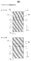
- the relatively small range value of theta 0 is 0 to 10 degrees, by the pitch P 1 of the third texture 15 substantially equal the pitch P 2 of the first Kusucha 16, the moire pattern between each occurrence This is easy to use and can be used effectively. Further, when the line-of-sight position is changed with respect to the light guide 11, the moire pattern moves. As a result, a vehicular lamp that urges surrounding vehicles and pedestrians to call attention can be realized.
- a relatively large value of 10 to 45 degrees may be selected as the value of ⁇ 0 .
- the height D 2 of the protruding portion of the first texture 16 is a 0.03 ⁇ 0.1 mm, gradually increased toward the end portion from the introduction the optical unit 12. With this configuration, the light emission intensity at the propagation position of the light emitting unit 13 is made uniform.
- the angle ⁇ 3 is preferably 20 to 45 degrees, and ⁇ 4 is preferably 45 to 70 degrees. From the combination of these angles ⁇ 1 , ⁇ 2 , ⁇ 3 , and ⁇ 4 , light is emitted from the light emitting surface 13 a of the light emitting unit 13 of the light guide 11 in a direction substantially perpendicular to the surface.
- the height D 3 of the protrusion of the second texture 17 is substantially constant in the light guide, and a relationship of D 3 > D 2 is desirable. But the height D 3 may be periodically varied within a certain range. By periodically varying the depth, the direction of light incident from the outside of the light guide and totally reflected by the second texture 17 can be dispersed within a certain range. By adopting this configuration, when direct sunlight is incident on the light guide, the reflection direction can be dispersed to some extent, and an antiglare effect can be expected. Further, the second texture 17 may be made to meander somewhat rather than having a linear shape. With this configuration, the same antiglare effect as described above can be expected.
- the ratio of the area of the protrusion and the flat part in the second texture 17 is larger. From this viewpoint, the height D 3 of the protrusions of the second texture 17 and the pitch P 3 thereof are determined.
- FIG. 5 is a diagram for explaining the angle of the protrusions of the second texture 17 and the effect thereof.
- the angles ⁇ 5a and ⁇ 6a of the protrusions of the texture 17a are set to approximately 45 degrees.
- a light guide that reflects external light with high reflectivity is realized. it can.
- angles ⁇ 5b and ⁇ 6b of the protrusions of the texture 17b are each set to a value greater than 45 degrees, for example, approximately 50 degrees.
- the light 90b incident from above the outside is totally reflected substantially in the horizontal direction by the texture 17b of the facing surface 13b. Therefore, it is possible to realize a light guide body that reflects external light, particularly light from a relatively bright sky, in the horizontal direction with high reflectivity.
- the configuration (B) is effective as a reflector for recognizing surrounding vehicles and pedestrians in the daytime. Even if the angle of the texture 17 is set to less than 45 degrees, it is possible to reflect the light incident on the opposite surface of the texture in the light from the sky in the horizontal direction. Since the prospective angle becomes small with respect to the light from the light, the amount of reflected light decreases. For the above reasons, when the light guide is applied to a vehicular lamp, it is desirable that the texture angle be 45 degrees or more. When the light guide is applied to an indoor lighting fixture, the texture angle may be 45 degrees or less because it is not necessary to reflect light from the sky effectively.
- a part of the facing surface side 13b of the light emitting unit 13 is configured to totally reflect not only the light emitted from the solid light source 80 but also the light incident from the outside.
- a glittering light guide can be realized even when is turned off.
- the second texture 17 is formed substantially parallel to the direction (X direction) in which the light from the solid light source 80 propagates, the second texture 17 has little diffraction effect on the light from the light source 80. Therefore, the light from the light source 80 is selectively diffracted by the third and first textures 15 and 16.
- the textures 15 and 16 are configured so that the shape gradually increases from the light source 80 toward the propagation direction (X direction). That is, since the intensity of light propagating through the light emitting unit 13 of the light guide gradually decreases, the structure is configured to correct the diffraction effect, so that the light from the light source 80 is emitted substantially uniformly within the light emitting unit 13. It has the characteristic to make it.
- this period is longer than 0.1 mm and shorter than 10 mm.
- the period is shorter than 0.1 mm, the change in the groove shape becomes large, the diffraction effect on the light from the light source 80 becomes strong, the amount of light leaking from the light guide increases, and the light guide characteristics deteriorate.
- the period is longer than 10 mm, when direct sunlight is incident on the light guide, the height or depth of the second texture 17 changes or meanders to disperse the reflection direction to some extent. The width becomes too large and difficult to realize.
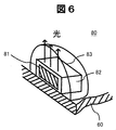
- FIG. 6 is a perspective view showing the configuration of the solid light source 80.
- an LED chip 81 that is a light emitting element is mounted on the substrate 60.
- a resin cap 83 for improving the light emission distribution characteristics of the LED light source may be formed outside the resin cap 83.
- the amount of light emitted from the LED chip 81 in the vertical direction with respect to the chip can be increased, and an effective brighter light source can be realized.
- a phosphor layer 82 that absorbs light from the LED chip 81 and emits fluorescence may be formed outside the LED chip 81 for the purpose of changing the emission spectrum characteristics of the solid light source 80 as necessary.
- the light source device of the first embodiment not only the light emitted from the solid-state light source but also the light incident from the outside is totally reflected. It can be applied to lamps that can be recognized by other vehicles and pedestrians, and highly illuminating devices used in vehicles and indoors.
- FIG. 7 is a diagram showing other shapes of the first texture 26 and the second texture 27 formed on the facing surface side 23b of the light emitting unit 23 as a second embodiment of the light source device according to the present invention.
- (A) is a perspective view
- (B) and (C) are X-direction and Y-direction cross-sectional views, respectively.
- a third texture 25 (not shown) formed on the light emitting side 23a of the light emitting unit 23 is the same as the third texture 15 of the first embodiment, and is guided to the light source device 20 of the present embodiment.
- the overall configuration of the light body 21 is the same as that of the light source device 10 and the light guide 11 of the first embodiment.
- the direction of the groove of the third texture 25 is inclined by the angle ⁇ 0 from the Y direction in the same manner as the third texture 15 of the first embodiment, and therefore the third texture 25 is also formed in this embodiment.
- the first texture 26 are disposed with an angle of ⁇ 0 relative to each other. By appropriately selecting the value of the angle ⁇ 0 , a moire pattern is generated between the third texture 25 and the first texture 26 and can be used effectively.
- FIG. 8 is a diagram for explaining the groove angle of the second texture 27 and its effect.
- the groove angles ⁇ 5a and ⁇ 6a of the texture 27a are set to approximately 45 degrees.
- the light 90a incident from the output side 23a from the outside is totally reflected in the same direction as the incident direction by the texture 27a of the opposing surface 23b, a light guide that reflects external light with high reflectivity is realized. it can.
- the groove angles ⁇ 5b and ⁇ 6b of the texture 27b are each set to a value larger than 45 degrees, for example, approximately 50 degrees.
- the light 90b incident from above the outside is totally reflected substantially in the horizontal direction by the texture 27b of the facing surface 23b. Therefore, it is possible to realize a light guide body that reflects external light, particularly light from a relatively bright sky, in the horizontal direction with high reflectivity.
- a part of the facing surface side 23b of the light emitting unit 23 has a structure that totally reflects not only the light emitted from the solid light source 80 but also the light incident from the outside.
- a glittering light guide can be realized even when is turned off.
- FIG. 9 is a sectional view showing the third embodiment of the light source device according to the present invention.
- the light source device 30 propagates the light generated from the two solid light sources 80a and 80b arranged at both ends of the light guide 31 to the light guide 31 and emits the light from the light emitting unit 33 to the outside (upward in the drawing). is there.
- the light emitting side of the light emitting portion 33 is indicated by 33a, and the opposite surface is indicated by 33b.
- the two solid light sources 80a and 80b are mounted on the substrates 70a and 70b, respectively, and are fixed to the support 71 together with the light guide 31 by fixtures 73a and 73b and screws 75a and 75b.
- a reflective film 72 is formed on the surface of the support 71 facing the light emitting portion 33.
- the reflective film 72 may be formed on the facing surface 33 b of the light emitting unit 33.
- FIG. 10A and 10B are perspective views of the light guide body 31 constituting the light source device 30.
- FIG. 10A is a view seen from the light emitting side 33a
- FIG. 10B is a view seen from the facing surface side 33b.
- the light guide 31 made of a transparent material has introduction light portions 32a and 32b for introducing light from the solid light sources 80a and 80b at both ends, and a light emitting portion 33 for emitting light to the outside at the center.
- the light emitting section 33 is a rod having a square cross section, thereby realizing a light source that emits light in a linear shape.
- the introduction light portions 32a and 32b are formed with substantially frustoconical concave grooves as light receiving portions 34a and 34b for fitting the fixed light sources 80a and 80b.
- a third texture 35 having a pitch P 0 period is formed on the light emitting side 33 a of the light emitting unit 33, and a first texture 36 having a pitch P 2 period is formed on the facing surface 33 b of the light emitting unit 33, forming a second texture 37 of the period of the pitch P 3 substantially perpendicular thereto.
- the shapes of these textures 35, 36, and 37 are the same as those in the first and second embodiments. However, since light enters from the two solid light sources 80a and 80b arranged at both ends of the light guide 31, the third texture
- the shapes (angles) of the texture 35 and the first texture 36 are approximately symmetrical in the X direction (in FIGS. 3, 4, and 7, ⁇ 1 ⁇ 2 , ⁇ 3 ⁇ 4 ).
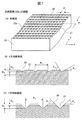
- FIG. 11 is a diagram showing other shapes of the first texture 46 and the second texture 47 formed on the facing surface side 43b of the light emitting unit 43 as a fourth embodiment of the light source device according to the present invention.
- a frustoconical pattern is formed two-dimensionally as the first texture 46, and a groove is formed in the X direction as the second texture 47.
- the first texture 46 is not limited to the prism shape as long as it has a shape that intersects the light propagating through the light emitting unit 43 in the X direction.
- the shape may be a dome shape or the like.
- the light source devices of Examples 1 to 4 described above can be provided with a vehicle lamp having excellent visibility by being attached to at least one of the front, side, rear and interior of the vehicle.
- the light source device is mainly used as a vehicle lamp, but the present invention is not limited to this. That is, the third texture formed in a direction substantially parallel to the light propagating through the light guide has a function of totally reflecting the light inside the light guide, so that a metal film such as aluminum is formed on the surface of the light guide. Therefore, it is possible to realize a lighting device that exhibits metallic luster and is low in cost and highly attractive.
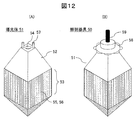
- FIG. 12 is a perspective view illustrating a configuration of a lighting apparatus according to the fifth embodiment.
- (A) shows the part of the light guide 51
- (B) shows an example applied to the illumination device 50.
- the light guide 51 includes an introduction light portion 52 and a light emission portion 53.
- the introduction light part 52 has a concave light receiving part 54 and a connecting part 57 into which a solid light source (not shown) is fitted.
- the light guide 51 is formed of a transparent resin such as acrylic, and the metal connecting portion is integrally formed with the light guide 51 by insert molding.
- a first texture 55 having a periodic shape is formed in a direction (a substantially horizontal direction in the drawing) in which a part of the light propagating through the light guide 51 is diffracted to the outside.
- a second texture 56 is formed so as to be superimposed in a direction substantially parallel to the light propagating through the light guide 51 (substantially perpendicular to the drawing).
- the shapes of the textures 55 and 56 the shapes shown in FIGS. 4, 7, and 11 can be applied.
- the inclination angle of the second texture 56 does not need to be 45 degrees or more, and a critical angle of 43 degrees at which total reflection of light occurs. It only needs to be around. By adopting this configuration, even when a structure in which the second texture 56 is formed in the direction of the side surface 4 is adopted, it is easy to remove the mold at the time of molding, and productivity is improved.
- the light guide 51 is connected to a cover 58 by a connector 57, and a power cable 59 is connected to the upper portion of the cover 58.
- the lighting fixture 50 having the above configuration is used by being attached to a ceiling surface, a wall surface, or outdoors.
- the second texture 56 is formed so as to overlap the four side surfaces of the light guide 51 and the four sides of the quadrangular pyramid. With this configuration, the light inside the light guide 51 is totally reflected many times by the second texture 56, the light is confined to some extent, and a part is diffracted by the third texture 56 and emitted to the outside. A brilliant lighting fixture can be realized.
Landscapes
- Engineering & Computer Science (AREA)
- General Engineering & Computer Science (AREA)
- Physics & Mathematics (AREA)
- Microelectronics & Electronic Packaging (AREA)
- Optics & Photonics (AREA)
- Planar Illumination Modules (AREA)
Abstract
光源装置(10)は、固体光源(80)と、固体光源から出射された光を伝搬して外部に出射する導光体(11)とを備える。導光体(11)は、少なくとも光を出射する第1の面(13a)および第1の面に対向して略平行な第2の面(13b)を有する。第2の面(13b)には、導光体を伝搬する光を回折する第1のテクスチャー(16)と、第1のテクスチャーに略直交し、導光体を伝搬する光の少なくとも一部を全反射する第2のテクスチャー(17)が重畳されて形成される。また第1の面(13a)には、導光体を伝搬する光を回折する第3のテクスチャー(15)を形成しても良い。
Description
本発明は、線状もしくは面状の光源として利用可能な光源装置に関し、特に、天井に取り付ける照明器具(シーリングライト)、更には自動車等の移動体における車両用灯具として好適に利用可能な光源装置に関する。
車両用灯具などの光源装置として、固体光源からの光を透明部材からなる導光体に入射させ、前記光を導光体表面に形成された凹凸形状により散乱させることにより、導光体からの光を取り出す構成が知られている。例えば特許文献1では、導光体に形成する凹凸形状を微細なパターンにすることにより、個々のパターンに起因する明暗模様を見えなくし、光源装置の見た目の質感の向上を図っている。
また照明装置として、光源からの光を導光体に導き、その上に形成された凹凸形状により光を反射させ、その光を導光体の下部に設置された反射型表示装置を照明する構成が知られる。例えば特許文献2に記載のフロントライト照明装置は、外部環境が明るい昼間屋外などで外部環境光を反射型表示装置の照明として活用でき、明るい環境下でも反射型表示装置の視認性が確保されることが記載される。
しかしながら、特許文献1の構成においては、個々の微細パターンに起因する明暗模様が見えない構成にすることにより、限定した評価基準上での光源装置の質感の向上はある程度期待できるが、明るい昼間での使用を考えると、その明るさに打ち勝つための強力な光源が必要となる。
また、特許文献2の構成では、導光体以外にその背面に別途反射体を設けることが必須であり、車両用灯具として適用するためにはコストが増加し好ましくない。
本発明の目的は、上述した課題に鑑み、低コストで製造可能、かつ視認性が良く趣向性が高い光源装置、及びこれを利用した照明器具や車両用灯具を提供することにある。
本発明は、固体光源と、固体光源から出射された光を伝搬して外部に出射する導光体とを備えた光源装置であって、導光体は、少なくとも光を出射する第1の面および第1の面に対向して略平行な第2の面を有し、第2の面には、導光体を伝搬する光を回折する第1のテクスチャーと、第1のテクスチャーに略直交し、導光体を伝搬する光の少なくとも一部を全反射する第2のテクスチャーが重畳されて形成された構成とする。
本発明によれば、低コストで製造可能、かつ視認性が良く高級感のある照明器具や車両用灯具に適用可能な光源装置を提供できる。
以下、本発明の実施の形態について、図面を参照しながら詳細に説明する。
図1は、本発明に係る光源装置の第1の実施例を示す断面構成図である。光源装置10は、固体光源80から発生された光を導光体11に伝搬させ、発光部13から外部(図面上方向)に出射させるものである。発光部13の光出射側(上面側)を13a、これに対向して略平行な対向面(下面側)を13bで示す。固体光源80は基板60に搭載され、導光体11とともに、固定具63,64やネジ65,66によって支持体61に固定されている。なお、支持体61の発光部13に対向する面には反射膜62を形成したり、導光体の前記対向面13bに反射膜を用いても良い。
図2は、光源装置10を構成する導光体11の斜視図であり、(A)は光出射側13aから見た図、(B)は対向面側13bから見た図である。透明材料からなる導光体11は、固体光源80からの光を導入する導入光部12と、外部に光を出射する発光部13を有する。発光部13は断面が四角形の棒状とすることで、線状に発光する光源装置を実現する。導入光部12には固定光源80を嵌合する受光部14として、略円錐台形状の凹溝を形成している。
発光部13には、光を出射する光出射側13aとそれと略平行となる対向面13bを有する。対向面13bには、略プリズム凸形状でピッチP2の周期となる第1のテクスチャー16と、これに略直交する略プリズム凸形状でピッチP3の周期となる第2のテクスチャー17が形成されている。
また光出射側13aには、必須ではないが、図3に示すような第3のテクスチャー15を形成してもよい。第3のテクスチャーを形成することにより、光出射側13aより出射する光の方向の自由度がより高くなる。
図3は、発光部13の光出射側13aに形成する第3のテクスチャー15の詳細形状を示す図で、(A)は斜視図、(B)はX方向断面図である。(A)で示すように、第3のテクスチャー15として直線状の溝が形成されている。なお、第3のテクスチャー15の溝の方向は、発光部13の幅方向(Y方向)から角度θ0だけ傾いて形成している。溝の断面形状は(B)で示すように、深さD1、角度θ1,θ2のプリズム凹形状となっている。深さD1は0.03~0.1mmで、導入光部12から端部に向け徐々に深くなる形状とする。この構成により、発光部13における伝搬方向位置での発光強度が均一化される。また角度θ1は20~45度、θ2は45~70度が好ましい。この場合、これらの角度を選択することにより、光出射側13aから出射する光の方向を面に対して鉛直方向に制御できる。光の出射角度が、光出射側13a面の鉛直方向に限らなければ、前記第3のテクスチャー15を省略することも可能である。
図4は、発光部13の対向面側13bに形成する第1のテクスチャー16と第2のテクスチャー17の詳細形状を示す図で、(A)は斜視図、(B)と(C)はそれぞれX方向、Y方向断面図である。(A)(B)で示すように、Y方向には第1のテクスチャー16として、略プリズム凸形状で高さD2の突起部をピッチP2の周期で形成している。また(A)(C)で示すように、X方向には第2のテクスチャー17として、略プリズム凸形状で高さD3の突起部をピッチP3の周期で形成している。第1のテクスチャー16の方向と第2のテクスチャー17の方向は略直交している。
第3のテクスチャー15の方向と第1のテクスチャー16の方向は角度θ0だけ傾いている。ここに角度θ0の値は、0~30度の範囲で適宜に選択する。θ0の値が0~10度と比較的小さな範囲では、第3のテクスチャー15のピッチP1と第1のクスチャー16のピッチP2を略等しくすることにより、それぞれの間でモアレ模様が発生しやすく、これを有効に利用できる。また、導光体11に対して視線位置を変化させるとモアレ模様が移動する。これにより、周囲の車両および歩行者に対し、より注意喚起を促す車両用灯具が実現できる。一方、モアレ模様を顕在化させたくない場合は、θ0の値を10~45度と比較的大きな値を選択すれば良い。この構成とすることにより、モアレ模様の周期はより細かくなり、モアレ模様の視認性を低下することが可能である。
なお、θ0の値が45度より大きくなると、導光体11の発光部13を長手方向に伝搬する光に対して各々のテクスチャー間の角度が小さくなるので、光の回折方向が発光部13の法線に対してずれが大きくなり好ましくない。
第1のテクスチャー16の突起部の高さD2は、0.03~0.1mmで、導入光部12から端部に向け徐々に大きくする。この構成により、発光部13の伝搬位置における発光強度が均一化される。また角度θ3は20~45度、θ4は45~70度が好ましい。これらの角度θ1、θ2、θ3、θ4の組合せより、導光体11の発光部13の光出射面13aから、面に対してほぼ垂直方向に光が出射される。
一方、第2のテクスチャー17の突起部の高さD3は、導光体内でほぼ一定となっており、D3>D2なる関係が望ましい。ただ前記高さD3は、ある範囲内で周期的に変動させても良い。深さを周期的に変動させることにより、導光体外部より入射して、第2のテクスチャー17により全反射される光の方向をある範囲で分散させることが可能となる。本構成を採用することにより、太陽光の直射光が導光体に入射した場合、その反射方向をある程度分散でき、防眩効果が期待できる。また、前記第2のテクチャー17を直線形状とはせず、多少蛇行させても良い。この構成により、前記と同様の防眩効果が期待できる。また、後述する外光反射率の観点から、第2のテクスチャー17における突起部と平坦部の面積の割合は、突起部の面積を大きくした方が好ましい。この観点より、第2のテクスチャー17の突起部の高さD3およびそのピッチP3を決定する。
図5は、第2のテクスチャー17の突起部の角度とその効果を説明する図である。
(A)では、テクスチャー17aの突起部の角度θ5a、θ6aを各々略45度に設定している。この場合、外部より出射側13aから入射した光90aは、対向面13bのテクスチャー17aによりほぼ入射した方向と同方向に全反射されるため、外光を高反射率で反射する導光体が実現できる。
(A)では、テクスチャー17aの突起部の角度θ5a、θ6aを各々略45度に設定している。この場合、外部より出射側13aから入射した光90aは、対向面13bのテクスチャー17aによりほぼ入射した方向と同方向に全反射されるため、外光を高反射率で反射する導光体が実現できる。
また(B)では、テクスチャー17bの突起部の角度θ5b、θ6bは、各々45度より大きな値、例えば各々略50度に設定している。この場合、外部の上方より入射した光90bは、対向面13bのテクスチャー17bにより、ほぼ水平方向に全反射される。そのため、外光、特に比較的明るい空からの光を、高反射率で水平方向に反射する導光体が実現できる。
特に(B)の構成は、昼間に車両の存在を周囲の車両および歩行者に対して認識させるための反射体として有効である。なお、テクスチャー17の角度を45度未満に設定しても、空からの光の中でテクスチャーの反対面に入射した光を、水平方向に反射することが可能であるが、前記反対面は空からの光に対して見込み角が小さくなるので、反射光量が少なくなる。以上の理由により、導光体を車両用灯具に適用する場合は、テクスチャー角度を45度以上にすることが望ましい。また導光体を屋内の照明器具に適用する場合は、この空からの光を有効に反射する必要がないので、テクスチャー角は45度以下でも良い。
いずれにおいても本構成では、発光部13の対向面側13bの一部が固体光源80から出射された光ばかりではなく、外部から入射した光を全反射する構造になっているので、固体光源80がオフの状態でもきらびやかな導光体を実現できる。
第2のテクスチャー17は、固体光源80からの光が伝搬する方向(X方向)に略平行に形成されているため、光源80からの光に対する回折作用は少ない。従って、光源80からの光は、第3、第1のテクスチャー15,16により選択的に回折される。
またテクスチャー15,16は、光源80から伝搬方向(X方向)に向け、徐々に形状が大きくなるように構成している。すなわち、導光体の発光部13を伝搬する光の強度が徐々に弱くなるのに対して、回折作用を補正する構成としているので、光源80からの光を発光部13内で略均一に発光させる特性を有する。
またこの光源80からの光に対する回折作用の観点から、前記第2のテクスチャー17の深さを変動させたり蛇行させたりする場合、この周期は0.1mmより長くかつ10mmより短い方が望ましい。周期が0.1mmより短くなると、溝形状の変化が大きくなることにより、光源80からの光に対する回折作用が強くなり、導光体から漏れ出す光が多くなり、導光特性が低下してしまう。一方、周期が10mmより長くなると、太陽光の直射光が導光体に入射した場合、その反射方向をある程分散させるための、前記第2のテクスチャー17の高さあるいは深さの変化あるいは蛇行幅が大きくなりすぎ、実現が困難となる。
図6は、固体光源80の構成を示す斜視図である。固体光源80は、発光素子であるLEDチップ81が基板60にマウントされる。さらに、その外側にLED光源の発光分布特性を改善する樹脂キャップ83を形成しても良い。樹脂キャップ83を設けることにより、LEDチップ81からチップに対して鉛直方向の出射される光量を増大させることができ、実効的により明るい光源が実現できる。なお、必要に応じて固体光源80の発光スペクトル特性を変化させる目的で、LEDチップ81からの光を吸収し蛍光を発する蛍光体層82をLEDチップ81の外側に形成しても良い。
実施例1の光源装置によれば、固体光源から出射された光ばかりではなく、外部から入射した光を全反射する構造になっているので、夜間に限定されず昼間においても車両の存在を周囲の車両および歩行者に対して認識させる灯具や、車両内および屋内に用いる趣向性の高い照明装置に適応できる。
図7は、本発明に係る光源装置の第2の実施例として、発光部23の対向面側23bに形成する第1のテクスチャー26と第2のテクスチャー27の他の形状を示す図で、(A)は斜視図、(B)と(C)はそれぞれX方向、Y方向断面図である。なお、発光部23の光出射側23aに形成する第3のテクスチャー25(図示せず)は、実施例1の第3のテクスチャー15と同様であり、また、本実施例の光源装置20と導光体21の全体構成は、実施例1の光源装置10、導光体11と同様である。
(A)(B)で示すように、Y方向には第1のテクスチャー26として、略プリズム凹形状で深さD2の溝をピッチP2の周期で形成している。また(A)(C)で示すように、X方向には第2のテクスチャー27として、略プリズム凹形状で深さD3の溝をピッチP3の周期で形成している。第1のテクスチャー26の方向と第2のテクスチャー27の方向は略直交している。
なお、第3のテクスチャー25の溝の方向は、実施例1の第3のテクスチャー15と同様にY方向から角度θ0だけ傾いて形成しているので、本実施例でも、第3のテクスチャー25と第1のテクスチャー26は相対的に角度θ0傾いて配置される。角度θ0の値を適宜選択することで、第3のテクチャー25と第1のテクチャー26間でモアレ模様を発生させ、有効に利用できる。
図8は、第2のテクスチャー27の溝の角度とその効果を説明する図である。
(A)では、テクスチャー27aの溝の角度θ5a、θ6aを各々略45度に設定している。この場合、外部より出射側23aから入射した光90aは、対向面23bのテクスチャー27aによりほぼ入射した方向と同方向に全反射されるため、外光を高反射率で反射する導光体が実現できる。
(A)では、テクスチャー27aの溝の角度θ5a、θ6aを各々略45度に設定している。この場合、外部より出射側23aから入射した光90aは、対向面23bのテクスチャー27aによりほぼ入射した方向と同方向に全反射されるため、外光を高反射率で反射する導光体が実現できる。
また(B)では、テクスチャー27bの溝の角度θ5b、θ6bは、各々45度より大きな値、例えば各々略50度に設定している。この場合、外部の上方より入射した光90bは、対向面23bのテクスチャー27bにより、ほぼ水平方向に全反射される。そのため、外光、特に比較的明るい空からの光を、高反射率で水平方向に反射する導光体が実現できる。
いずれにおいても本構成では、発光部23の対向面側23bの一部が、固体光源80から出射された光ばかりではなく外部から入射した光を全反射する構造になっているので、固体光源80がオフの状態でもきらびやかな導光体を実現できる。
このような構成とすることで、実施例1の場合と同様に、固体光源から出射された光ばかりではなく、外部から入射した光を全反射する構造になっているので、夜間に限定されず昼間においても車両の存在を周囲の車両および歩行者に対して認識させる灯具や、車両内および屋内に用いる趣向性の高い照明装置を実現できる。
図9は、本発明に係る光源装置の第3の実施例を示す断面構成図である。光源装置30は、導光体31の両端に配置した2つの固体光源80a,80bから発生された光を導光体31に伝搬させ、発光部33から外部(図面上方向)に出射させるものである。発光部33の光出射側を33a、これの対向面を33bで示す。2つの固体光源80a,80bはそれぞれ基板70a,70bに搭載され、導光体31とともに、固定具73a,73bやネジ75a,75bによって支持体71に固定されている。支持体71の発光部33に対向する面には反射膜72を形成している。なお、反射膜72は発光部33の対向面33bに形成しても良い。
図10は、光源装置30を構成する導光体31の斜視図であり、(A)は光出射側33aから見た図、(B)は対向面側33bから見た図である。透明材料からなる導光体31は、その両端に固体光源80a,80bからの光を導入する導入光部32a,32bを有し、中央部に外部に光を出射する発光部33を有する。発光部33は断面が四角形の棒状とすることで、線状に発光する光源を実現する。導入光部32a,32bには固定光源80a,80bを嵌合する受光部34a,34bとして、略円錐台形状の凹溝を形成している。
発光部33の光出射側33aには、ピッチP0の周期となる第3のテクスチャー35を形成し、発光部33の対向面33bにはピッチP2の周期となる第1のテクスチャー36と、これに略直交するピッチP3の周期となる第2のテクスチャー37を形成している。これらのテクスチャー35,36,37の形状は実施例1や実施例2と同様であるが、導光体31の両端に配置した2つの固体光源80a,80bから光が入射するため、第3のテクスチャー35と第1のテクスチャー36の形状(角度)は、X方向に略対称とする(図3、図4、図7において、θ1≒θ2、θ3≒θ4)。
図11は、本発明に係る光源装置の第4の実施例として、発光部43の対向面側43bに形成する第1のテクスチャー46と第2のテクスチャー47の他の形状を示す図である。この例では、第1のテクスチャー46として円錐台形状のパターンを2次元状に形成し、第2のテクスチャー47としてX方向に溝を形成している。このように、第1のテクスチャー46は、発光部43をX方向に伝搬する光に対して交差する形状であれば良いので、プリズム形状に限定されるものではなく、円錐台形状や円錐形状、ドーム形状などの形状とすることができる。
上記の実施例1~4の光源装置は、車両の少なくとも正面、側面、後面、室内のいずれかに取り付けることで、視認性の優れた車両用灯具を提供できる。
前記した各実施例では、光源装置を車両用灯具として利用することを主体に説明したが、本発明はこれに限定されるものではない。すなわち、導光体を伝搬する光に対して略平行方向に形成された第3のテクスチャーは、導光体内部の光を全反射する働きがあるので、導光体表面にアルミ等の金属膜を形成することなく、金属光沢を示し、低コストで趣向性の高い照明器具を実現できる。
図12は、実施例5に係る照明器具の構成を示す斜視図である。(A)は導光体51の部分、(B)は照明装置50に適用した例を示す。導光体51は、導入光部52と発光部53からなる。導入光部52は、固体光源(図示せず)が嵌合する凹形状の受光部54および連結部57を有する。導光体51はアクリル等の透明性の樹脂で形成され、金属製の連結部はインサート成型により導光体51と一体に成型される。
発光部53の側面および底面には、導光体51を伝搬する光の一部を外部に回折する方向(図面略水平方向)に周期状の第1のテクスチャー55が形成されており、これに重畳して、導光体51を伝搬する光に対して略平行方向(図面略垂直方向)に第2のテクスチャー56が形成されている。テクスチャー55,56の形状は、図4,図7,図11に示したような形状が適用できる。ただし本実施例では、空からの外光を水平方向に反射する必要がないので、第2のテクスチャー56の傾斜角は45度以上ある必要はなく、光の全反射が発生する臨界角43度程度あれば良い。この構成にすることにより、側面4方向に第2のテクスチャー56を形成した構造を採用しても、成型時に型抜きが容易になり、生産性が向上する。
導光体51は、連結具57によりカバー58と連結され、さらにカバー58の上部には、電源ケーブル59が連結されている。以上の構成の照明器具50は、天井面あるいは壁面あるいは屋外に取り付けて使用する。
本実施例では、導光体51の側面4面および四角錐側面の4面に、第2のテクスチャー56が重畳して形成されている。この構成により導光体51内部の光は、第2のテクスチャー56により多数回全反射され、光がある程度閉じ込められ、一部が第3のテクスチャー56により回折され外部に放出されるので、非常にきらびやかな照明器具が実現できる。
10,30…光源装置、
11,31,51…導光体、
12,32,52…光導入部、
13,23,33,43,53…発光部、
14,34,54…受光部、
15,16,17,26,27,35,36,37,46,47,55,56…テクスチャー、
50…照明器具、
60,70…基板、
61,71…支持体、
80…固体光源。
11,31,51…導光体、
12,32,52…光導入部、
13,23,33,43,53…発光部、
14,34,54…受光部、
15,16,17,26,27,35,36,37,46,47,55,56…テクスチャー、
50…照明器具、
60,70…基板、
61,71…支持体、
80…固体光源。
Claims (17)
- 固体光源と、該固体光源から出射された光を伝搬して外部に出射する導光体とを備えた光源装置であって、
前記導光体は、少なくとも光を出射する第1の面および該第1の面に対向して略平行な第2の面を有し、
前記第2の面には、前記導光体を伝搬する光を回折する第1のテクスチャーと、該第1のテクスチャーに略直交し、前記導光体を伝搬する光の少なくとも一部を全反射する第2のテクスチャーが重畳されて形成されていることを特徴とする光源装置。 - 請求項1に記載した光源装置において、
前記第1の面には、前記第1のテクスチャーと略平行となる相対角が10°以下の角度で線状に配置された第3のテクスチャーが形成されていることを特徴とする光源装置。 - 請求項1に記載した光源装置において、
前記第1の面には、前記第1のテクスチャーと相対角が10°より大きくかつ45°以下となる線状に配置された第3のテクスチャーが形成されていることを特徴とする光源装置。 - 請求項2に記載した光源装置において、
前記第3のテクスチャーは、プリズム形状、円錐形状、円錐台形状、ドーム形状のいずれかに形成されていることを特徴とする光源装置。 - 請求項1に記載した光源装置において、
前記第2のテクスチャーは凸形状のプリズム形状に形成され、該凸形状のプリズムの間の平坦面に、前記第1のテクスチャーが凸形状に形成されていることを特徴とする光源装置。 - 請求項1に記載した光源装置において、
前記第2のテクスチャーは凹形状のプリズム形状に形成され、該凹形状のプリズムの間の平坦面に、前記第1のテクスチャーが凹形状に形成されていることを特徴とする光源装置。 - 請求項1に記載した光源装置において、
前記第2のテクスチャーは、凸または凹形状のプリズム形状に形成され、該プリズム形状の高さもしくは深さが周期的に変動していることを特徴とする光源装置。 - 請求項1に記載した光源装置において、
前記第2のテクスチャーは、凸または凹形状のプリズム形状に形成され、該プリズム形状が周期的に蛇行していることを特徴とする光源装置。 - 請求項5に記載した光源装置において、
前記第2のテクスチャーである凸形状のプリズムの高さは、前記第1のテクスチャーである凸形状の高さより大きいことを特徴とする光源装置。 - 請求項6に記載した光源装置において、
前記第2のテクスチャーである凹形状のプリズムの深さは、前記第1のテクスチャーである凹形状の深さより大きいことを特徴とする光源装置。 - 請求項1に記載した光源装置において、
前記導光体は線状であり、
前記第2のテクスチャーは、傾斜角が45度以上のプリズム形状に形成されていることを特徴とする光源装置。 - 固体光源と、該固体光源から出射された光を伝搬して外部に出射する導光体とを備えた光源装置であって、
前記導光体は多面体により構成され、少なくとも複数の面には、前記導光体を伝搬する光を回折する第1のテクスチャーと、該第1のテクスチャーに略直交し、前記導光体を伝搬する光の少なくとも一部を全反射する第2のテクスチャーが重畳されて形成されていることを特徴とする光源装置。 - 請求項12に記載された光源装置において、
前記第1のテクスチャーはプリズム形状であることを特徴とする光源装置。 - 請求項13に記載された光源装置において、
前記第1および第2のテクスチャーは凸形状であり、前記第2のテクスチャーの凸形状の高さは前記第1のテクスチャーの凸形状の高さより大きいことを特徴とする光源装置。 - 請求項13に記載された光源装置において、
前記第1および第2のテクスチャーは凹形状であり、前記第2のテクスチャーの凹形状の深さは前記第1のテクスチャーの凹形状の深さより大きいことを特徴とする光源装置。 - 請求項1~11の何れか1項に記載された光源装置を、車両の少なくとも正面、側面、後面、室内のいずれかにに取り付けたことを特徴とする車両用灯具。
- 請求項12~15の何れか1項に記載した光源装置を光源とし、天井面あるいは壁面あるいは屋外に取り付けたことを特徴とする照明器具。
Priority Applications (1)
| Application Number | Priority Date | Filing Date | Title |
|---|---|---|---|
| PCT/JP2015/052040 WO2016120974A1 (ja) | 2015-01-26 | 2015-01-26 | 光源装置及びそれを利用した照明器具と車両用灯具 |
Applications Claiming Priority (1)
| Application Number | Priority Date | Filing Date | Title |
|---|---|---|---|
| PCT/JP2015/052040 WO2016120974A1 (ja) | 2015-01-26 | 2015-01-26 | 光源装置及びそれを利用した照明器具と車両用灯具 |
Publications (1)
| Publication Number | Publication Date |
|---|---|
| WO2016120974A1 true WO2016120974A1 (ja) | 2016-08-04 |
Family
ID=56542633
Family Applications (1)
| Application Number | Title | Priority Date | Filing Date |
|---|---|---|---|
| PCT/JP2015/052040 WO2016120974A1 (ja) | 2015-01-26 | 2015-01-26 | 光源装置及びそれを利用した照明器具と車両用灯具 |
Country Status (1)
| Country | Link |
|---|---|
| WO (1) | WO2016120974A1 (ja) |
Citations (3)
| Publication number | Priority date | Publication date | Assignee | Title |
|---|---|---|---|---|
| JP2000305073A (ja) * | 1999-04-22 | 2000-11-02 | Mitsubishi Electric Corp | 液晶表示装置用バックライト |
| JP3164028U (ja) * | 2010-08-30 | 2010-11-11 | 嘉威光電股▲分▼有限公司 | 光学薄膜、及び、光学薄膜を応用したバックライトモジュール |
| JP2011192468A (ja) * | 2010-03-12 | 2011-09-29 | Hitachi Displays Ltd | 照明装置および液晶表示装置 |
-
2015
- 2015-01-26 WO PCT/JP2015/052040 patent/WO2016120974A1/ja active Application Filing
Patent Citations (3)
| Publication number | Priority date | Publication date | Assignee | Title |
|---|---|---|---|---|
| JP2000305073A (ja) * | 1999-04-22 | 2000-11-02 | Mitsubishi Electric Corp | 液晶表示装置用バックライト |
| JP2011192468A (ja) * | 2010-03-12 | 2011-09-29 | Hitachi Displays Ltd | 照明装置および液晶表示装置 |
| JP3164028U (ja) * | 2010-08-30 | 2010-11-11 | 嘉威光電股▲分▼有限公司 | 光学薄膜、及び、光学薄膜を応用したバックライトモジュール |
Similar Documents
| Publication | Publication Date | Title |
|---|---|---|
| CN104819423B (zh) | 立体照明装置以及使用立体照明装置的车辆照明装置 | |
| JP6224110B2 (ja) | 自動車両の照明および/または合図装置 | |
| US8820964B2 (en) | Linear lighting system | |
| RU2605690C2 (ru) | Светильник | |
| CA2771416A1 (en) | A lighting device and a lens suitable for such a lighting device | |
| US10006603B2 (en) | Light reflector arrangement | |
| JPWO2012063759A1 (ja) | Led照明装置 | |
| CN104748072B (zh) | 使用线状光束的照明装置 | |
| US11592158B2 (en) | Lighting arrangement with optical composite for targeted illumination patterns | |
| JP2009131998A (ja) | 装飾用パネル | |
| US20140293649A1 (en) | Illumination device and automotive lamp | |
| JP2012182117A (ja) | 管型照明器具、管型照明器具用筐体及び両面内照式看板装置 | |
| JP2009291966A (ja) | 装飾用パネル | |
| US7217010B2 (en) | Reflector with negative focal length | |
| EP2653777A1 (en) | Lighting device and cove lighting module using the same | |
| WO2016120974A1 (ja) | 光源装置及びそれを利用した照明器具と車両用灯具 | |
| JP6826757B2 (ja) | 乗物用照明装置 | |
| GB2480758A (en) | Light guide with first and second light output surfaces | |
| JP5202602B2 (ja) | 透光性部材 | |
| JP2006044330A (ja) | 発光装置 | |
| TW201510592A (zh) | 照明裝置 | |
| WO2017046945A1 (ja) | 光源装置及びそれを利用した照明器具と車両用灯具 | |
| JP6668554B2 (ja) | サンバイザ | |
| JP2017157325A (ja) | 照明装置 | |
| JP7165875B2 (ja) | 照明用導光板及び照明装置 |
Legal Events
| Date | Code | Title | Description |
|---|---|---|---|
| 121 | Ep: the epo has been informed by wipo that ep was designated in this application |
Ref document number: 15879871 Country of ref document: EP Kind code of ref document: A1 |
|
| NENP | Non-entry into the national phase |
Ref country code: DE |
|
| NENP | Non-entry into the national phase |
Ref country code: JP |
|
| 122 | Ep: pct application non-entry in european phase |
Ref document number: 15879871 Country of ref document: EP Kind code of ref document: A1 |