WO2016120934A1 - 記録装置及び多重化方法 - Google Patents
記録装置及び多重化方法 Download PDFInfo
- Publication number
- WO2016120934A1 WO2016120934A1 PCT/JP2015/006274 JP2015006274W WO2016120934A1 WO 2016120934 A1 WO2016120934 A1 WO 2016120934A1 JP 2015006274 W JP2015006274 W JP 2015006274W WO 2016120934 A1 WO2016120934 A1 WO 2016120934A1
- Authority
- WO
- WIPO (PCT)
- Prior art keywords
- data
- recording
- instruction
- time
- unit
- Prior art date
- Legal status (The legal status is an assumption and is not a legal conclusion. Google has not performed a legal analysis and makes no representation as to the accuracy of the status listed.)
- Ceased
Links
Images


Classifications
-
- H—ELECTRICITY
- H04—ELECTRIC COMMUNICATION TECHNIQUE
- H04N—PICTORIAL COMMUNICATION, e.g. TELEVISION
- H04N5/00—Details of television systems
- H04N5/76—Television signal recording
- H04N5/91—Television signal processing therefor
- H04N5/92—Transformation of the television signal for recording, e.g. modulation, frequency changing; Inverse transformation for playback
- H04N5/9201—Transformation of the television signal for recording, e.g. modulation, frequency changing; Inverse transformation for playback involving the multiplexing of an additional signal and the video signal
- H04N5/9202—Transformation of the television signal for recording, e.g. modulation, frequency changing; Inverse transformation for playback involving the multiplexing of an additional signal and the video signal the additional signal being a sound signal
- H04N5/9203—Transformation of the television signal for recording, e.g. modulation, frequency changing; Inverse transformation for playback involving the multiplexing of an additional signal and the video signal the additional signal being a sound signal using time division multiplex
-
- G—PHYSICS
- G11—INFORMATION STORAGE
- G11B—INFORMATION STORAGE BASED ON RELATIVE MOVEMENT BETWEEN RECORD CARRIER AND TRANSDUCER
- G11B20/00—Signal processing not specific to the method of recording or reproducing; Circuits therefor
- G11B20/10—Digital recording or reproducing
-
- H—ELECTRICITY
- H04—ELECTRIC COMMUNICATION TECHNIQUE
- H04N—PICTORIAL COMMUNICATION, e.g. TELEVISION
- H04N5/00—Details of television systems
- H04N5/76—Television signal recording
- H04N5/765—Interface circuits between an apparatus for recording and another apparatus
- H04N5/77—Interface circuits between an apparatus for recording and another apparatus between a recording apparatus and a television camera
- H04N5/772—Interface circuits between an apparatus for recording and another apparatus between a recording apparatus and a television camera the recording apparatus and the television camera being placed in the same enclosure
-
- H—ELECTRICITY
- H04—ELECTRIC COMMUNICATION TECHNIQUE
- H04N—PICTORIAL COMMUNICATION, e.g. TELEVISION
- H04N9/00—Details of colour television systems
- H04N9/79—Processing of colour television signals in connection with recording
- H04N9/80—Transformation of the television signal for recording, e.g. modulation, frequency changing; Inverse transformation for playback
- H04N9/804—Transformation of the television signal for recording, e.g. modulation, frequency changing; Inverse transformation for playback involving pulse code modulation of the colour picture signal components
- H04N9/8042—Transformation of the television signal for recording, e.g. modulation, frequency changing; Inverse transformation for playback involving pulse code modulation of the colour picture signal components involving data reduction
-
- H—ELECTRICITY
- H04—ELECTRIC COMMUNICATION TECHNIQUE
- H04N—PICTORIAL COMMUNICATION, e.g. TELEVISION
- H04N9/00—Details of colour television systems
- H04N9/79—Processing of colour television signals in connection with recording
- H04N9/80—Transformation of the television signal for recording, e.g. modulation, frequency changing; Inverse transformation for playback
- H04N9/82—Transformation of the television signal for recording, e.g. modulation, frequency changing; Inverse transformation for playback the individual colour picture signal components being recorded simultaneously only
- H04N9/8205—Transformation of the television signal for recording, e.g. modulation, frequency changing; Inverse transformation for playback the individual colour picture signal components being recorded simultaneously only involving the multiplexing of an additional signal and the colour video signal
- H04N9/8211—Transformation of the television signal for recording, e.g. modulation, frequency changing; Inverse transformation for playback the individual colour picture signal components being recorded simultaneously only involving the multiplexing of an additional signal and the colour video signal the additional signal being a sound signal
Definitions
- the present invention relates to a recording apparatus and a multiplexing method.
- a technique called clip continuous recording is known.
- this technique when a set of recording instructions consisting of a recording start instruction and a recording stop instruction is repeated several times with a time interval, the data corresponding to the recording instructions for several times are combined into one recording data.
- the recording data is also called a clip or a stream.
- each video data corresponding to a period from a recording start instruction to a recording stop instruction and audio data corresponding to each video data are multiplexed as one recording data.
- AVCHD registered trademark
- Patent Document 1 discloses a technique for temporally correlating the encoded video data and the encoded audio data when the encoding process is paused and resumed.
- the data to be multiplexed is not compressed data, and multiplexing for clip continuous recording with compressed data as a target is still required.
- An object of the present invention is to provide a recording apparatus and a multiplexing method capable of performing multiplexing for clip continuous recording on compressed data while suppressing a time lag between audio and video. There is.
- video encoding means for compressing and encoding video data for each first data unit, and audio data for each second data unit having a different time length from the first data unit.
- a set of recording instructions consisting of a voice encoding means that compresses and encodes and a recording start instruction and a recording stop instruction are repeated with a time interval, from the recording start instruction to the recording stop instruction
- the video data encoded by the video encoding means corresponding to a period are connected to each other, and the video data and the audio data encoded by the audio encoding means corresponding to the video data are Multiplexing means for multiplexing as one record data, the speech encoding means continues encoding at least from the first recording instruction to the last recording instruction,
- the multiplexing means has a time shift amount between the video data and the audio data encoded by the audio encoding means corresponding to the video data equal to or less than the time length of the second data unit.
- a video encoding step of compressing and encoding video data for each first data unit, and audio data for each second data unit having a different time length from the first data unit When a set of recording instructions consisting of a voice encoding step and a recording start instruction and a recording stop instruction are repeated with a time interval, from the recording start instruction to the recording stop instruction.
- the audio encoding step continues encoding at least from the first recording instruction to the last recording instruction, and the multiplexing step includes the video data And the audio data encoded by the audio encoding step corresponding to each of the video data, the audio data encoded so that a time lag amount is equal to or less than the time length of the second data unit.
- a recording apparatus and a multiplexing method capable of performing multiplexing for clip continuous recording on compressed data while suppressing a time lag between audio and video. can do.
- FIG. 1 is a block diagram illustrating a configuration of the imaging apparatus according to the embodiment.
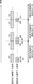
- FIG. 2 is a schematic diagram illustrating video data and audio data selected in the multiplexing process by the multiplexing unit according to the embodiment.
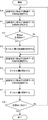
- FIG. 3 is a flowchart illustrating an example of the operation flow of the selection process of the multiplexing target in the multiplexing unit according to the embodiment.
- FIG. 4 is a schematic diagram illustrating temporal correspondence between video data and audio data selected based on the multiplexing target selection process according to the embodiment.
- FIG. 1 is a block diagram showing a configuration of an imaging apparatus 1 according to an embodiment of the present invention.
- the imaging device 1 includes an imaging unit 10, a sound acquisition unit 20, an operation unit 30, a recording device 40, and a recording medium 50.
- the voice acquisition unit 20 acquires voice data. Specifically, the voice acquisition unit 20 acquires voice data using, for example, a microphone. The voice acquisition unit 20 outputs the acquired voice data to the voice encoding unit 403 described later.
- the operation unit 30 includes buttons, a touch panel, and the like, and receives various instructions from the user including a set of recording instructions including a recording start instruction and a recording stop instruction.
- the recording stop instruction in the last recording instruction may be referred to as a recording completion instruction.
- a recording stop instruction other than the recording completion instruction may be referred to as a recording pause instruction.
- the operation unit 30 includes a recording button (not shown), and the user performs a recording start instruction and a recording stop instruction by pressing the recording button. For example, when the user presses the recording button, a recording start instruction is given, and when the user presses the recording button again, a recording stop instruction is given. For example, when the user presses the recording button for a long time, a recording end instruction is given.
- the recording apparatus 40 includes a recording operation reception unit 400, a video encoding unit 401, a video buffer 402, an audio encoding unit 403, an audio buffer 404, and a multiplexing unit 405. And a multiplexing buffer 406 and a recording medium interface (I / F) unit 407.
- the video buffer 402, the audio buffer 404, and the multiplexing buffer 406 are each configured by, for example, a FIFO (first-in first-out) format or a ring buffer format RAM (Random Access Memory).
- the recording operation receiving unit 400, the video encoding unit 401, the audio encoding unit 403, and the multiplexing unit 405 may be realized by hardware, or may be realized by a computer executing a program. .
- the recording operation reception unit 400 receives the recording start instruction and the recording stop instruction received by the operation unit 30 and notifies the multiplexing unit 405 of the instruction.
- the video encoding unit 401 compresses and encodes the video data output from the imaging unit 10 for each predetermined data unit.
- the video encoding unit 401 is an MPEG-4 AVC / H. It is compressed and encoded in a predetermined format such as H.264.
- the video encoding unit 401 performs encoding using 15 frames as a data unit.
- the video frame rate is 29.97 Hz
- the time per frame is 33.3 milliseconds.
- a group of 15 frames is handled as one GOP (Group Of Pictures) unit. That is, the time per GOP is 499.5 milliseconds. Therefore, the video encoding unit 401 encodes video data for 499.5 milliseconds as one unit.
- the video encoding unit 401 performs encoding in units of GOP including 15 frames.
- the video encoding unit 401 outputs the encoded video data to the video buffer 402.
- the data unit in the encoding of the video encoding unit 401 may be referred to as a first data unit.
- the video encoding unit 401 performs encoding regardless of the recording stop instruction at least during clip continuous recording, that is, from the first recording instruction to the last recording instruction. continuing.
- the video buffer 402 temporarily stores the encoded video data output from the video encoding unit 401.
- the audio encoding unit 403 compresses and encodes the audio data output from the audio acquisition unit 20 for each predetermined data unit.
- the speech encoding unit 403 compresses and encodes in a predetermined format such as Dolby Digital.
- the data unit in the encoding of the speech encoding unit 403 may be referred to as a second data unit.
- the time length of the second data unit is different from the time length of the first data unit.
- speech encoding section 403 encodes one frame as a second data unit, but one frame of Dolby Digital is composed of speech data for 32 millimeters.
- the video encoding unit 401 encodes video data for 499.5 milliseconds as a unit, whereas the audio encoding unit 403 sets audio data for 32 milliseconds as a unit. Is encoded as The audio encoding unit 403 outputs the encoded audio data to the audio buffer 404.
- the audio encoding unit 403 performs encoding regardless of the recording stop instruction at least during clip continuous recording, that is, from the first recording instruction to the last recording instruction. continuing.
- the audio buffer 404 temporarily stores the encoded audio data output from the audio encoding unit 403.
- the multiplexing unit 405 multiplexes the encoded video data stored in the video buffer 402 and the encoded audio data stored in the audio buffer 404 in a predetermined format.
- MPEG-TS Transport Stream
- the multiplexing unit 405 performs multiplexing according to MPEG-TS.
- the multiplexing unit 405 outputs the generated multiplexed data to the multiplexing buffer 406. Details of the multiplexing unit 405 will be described later.
- the multiplexing buffer 406 temporarily stores the multiplexed data generated by the multiplexing unit 405.
- the recording medium interface unit 407 is an interface for recording the multiplexed data stored in the multiplexing buffer 406 on the recording medium 50.
- the recording medium 50 is a randomly accessible recording medium such as a semiconductor memory card, an optical disk, or a hard disk.
- the recording medium 50 may be a semiconductor memory card mounted in a slot.
- the multiplexing unit 405 performs multiplexing as follows in the case of clip continuous recording. That is, the multiplexing unit 405 performs encoding corresponding to a period from a recording start instruction to a recording stop instruction when a set of recording instructions including a recording start instruction and a recording stop instruction is repeated with a time interval.
- the video data are connected to each other, and the video data and the encoded audio data corresponding to the video data are multiplexed as one recording data.
- the multiplexing unit 405 includes, among the encoded video data stored in the video buffer 402, based on the timing of the recording start instruction and the recording stop instruction notified from the recording operation reception unit 400. Select encoded video data to be used as a recording target.
- the selection of the encoded video data is performed in the first data unit.
- the multiplexing unit 405 selects encoded audio data to be adopted as encoded audio data corresponding to each video data from the encoded audio data stored in the audio buffer 404.
- the selection of the encoded audio data is performed in the second data unit.
- multiplexing section 405 performs multiplexing as shown below.
- the multiplexing unit 405 has a second time shift amount between each encoded video data corresponding to a period from a recording start instruction to a recording stop instruction, and encoded audio data corresponding to each video data.
- the audio data is selected and multiplexed in the second data unit from the encoded audio data in the second data unit so as to be equal to or less than the time length of the data unit.
- the multiplexing unit 405 performs multiplexing as follows.
- the first reference time is the start time of the encoded video data corresponding to the noticed recording instruction.
- the second reference time is the end time of the encoded video data corresponding to the noticed recording instruction.
- shifting the time of the audio data means that the original temporal correspondence between the audio data and the video data is broken and the audio data and the video data are made to correspond.
- the multiplexing unit 405 for the audio data shifted in time by the accumulated offset amount, the end time of the audio data in the second data unit at the end of the encoded audio data corresponding to the noticed recording instruction, The end point is determined so that the difference from the second reference time is not more than half the time length of the second data unit.
- the offset amount is defined as follows. The initial value of the offset amount is a difference between the start end of the encoded video data and the start end of the encoded audio data at the start of the first recording. The offset amount is determined every time when the start end of the encoded audio data corresponding to the recording instruction of interest is determined, the time length from the time corresponding to the first recording start instruction to the determined start end, and the first recording start time.
- the difference from the time length from the time corresponding to the start instruction to the first reference time is added.
- the offset amount includes the time length from the time corresponding to the first recording start instruction to the determined end for each determination of the end of the encoded audio data corresponding to the noticed recording instruction, The difference from the time length to the reference time is added.
- the added value is not only a positive value but also a negative value. For this reason, the accumulated offset amount takes a positive value or a negative value.
- FIG. 2 is a schematic diagram showing video data and audio data selected in the multiplexing process by the multiplexing unit 405.
- the encoded video data sequence and the encoded audio data sequence are shown in the first row. That is, the first row shows an example of encoded video data stored in the video buffer 402 and encoded audio data stored in the audio buffer 404.
- the second row when the second data unit audio data to be multiplexed is selected from the audio buffer 404 as the audio data corresponding to the first recording instruction, the second data unit audio to be terminated is selected.
- the second data unit audio to be terminated is selected.
- the second data unit audio data to be multiplexed when the second data unit audio data to be multiplexed is selected from the audio buffer 404 as the audio data corresponding to the second recording instruction, the second data unit audio to be used as the start point is selected.
- the second data unit audio to be terminated when the second data unit audio data to be multiplexed is selected from the audio buffer 404 as the audio data corresponding to the second recording instruction, the second data unit audio to be terminated is selected.
- the second data unit audio to be used as the start point is selected.
- each rectangle indicates video data in the first data unit or audio data in the second data unit, and the hatched rectangle indicates data selected as a multiplexing target. .
- Video data 100 is the start of video data corresponding to the first recording instruction.
- Video data 101 is the end of the video data corresponding to the first recording instruction.
- Video data 102 is video data following video data 101 in terms of time.
- the video data 103 is video data immediately before the video data 104 in terms of time.
- Video data 104 is the beginning of video data corresponding to the second recording instruction.
- Video data 105 is the end of video data corresponding to the second recording instruction.
- the video data 106 is video data that follows the video data 105 in terms of time.
- the video data 107 is video data immediately before the video data 108 in terms of time.
- Video data 108 is the start of video data corresponding to the third recording instruction.
- the audio data 200 to 214 indicate encoded audio data obtained during clip continuous recording.
- the audio data 200 is audio data at the time of the first recording start instruction.
- multiplexing section 405 selects the multiplexing target using the offset amount as described above.
- the initial value of the offset amount is 0.
- the multiplexing unit 405 selects encoded audio data corresponding to video data corresponding to the first recording instruction. At this time, the start time of the video data 100 is the first reference time, and the end time of the video data 101 is the second reference time.
- the multiplexing unit 405 Since the offset amount is 0, the multiplexing unit 405 does not shift the audio data in terms of time, and the start time of the second data unit at the start of the audio data corresponding to the first recording instruction and the first time The starting point is determined so that the difference from the reference time of 1 is less than half the time length of the second data unit. In the present embodiment, the half of the time length of the second data unit is 16 milliseconds. Therefore, as shown in the second row of FIG. 2, the multiplexing unit 405 determines the audio data 200 as the start of audio data corresponding to the first recording instruction.
- the time length from the time point corresponding to the first recording start instruction that is, the start time point of the video data 100 to the audio data 200 that is the determined start point
- the time point corresponding to the first recording start instruction ie, the video data 100
- the offset amount is not added after the start of audio data corresponding to the first recording instruction is determined.
- the multiplexing unit 405 does not shift the audio data in time, and the audio data of the second data unit at the end of the audio data corresponding to the first recording instruction is recorded.
- the end point is determined so that the difference between the end time point and the second reference time point is not more than half the time length of the second data unit.
- the difference between the end time point and the second reference time point is less than half the time length of the second data unit. Therefore, the multiplexing unit 405 determines the audio data 204 as the end of the audio data corresponding to the first recording instruction.
- the offset amount is updated as the end point is determined. Specifically, it corresponds to the time length from the time point corresponding to the first recording start instruction, that is, the start time point of the video data 100 to the end time point of the audio data 204 that is the determined end point, and the first recording start instruction.
- the offset amount is updated by adding the difference with the time length from the time point to the second reference time point.
- the offset amount after the update is Offset1. As shown in the second row of FIG. 2, Offset1 corresponds to the difference between the end point of the audio data 204 and the second reference time point.
- the multiplexing unit 405 selects encoded audio data corresponding to the video data corresponding to the second recording instruction.
- the start time of the video data 104 is the first reference time
- the end time of the video data 105 is the second reference time.
- the multiplexing unit 405 sets the first offset of the audio data in the second data unit at the start of the audio data corresponding to the second recording instruction and the first offset for the accumulated offset amount, that is, the audio data shifted in time by Offset1.
- the starting point is determined so that the difference from the reference time is less than half the time length of the second data unit.
- the audio data series is shifted by Offset 1 in the time delay direction, that is, in the right direction in the figure.
- the direction in which the audio data series is shifted is determined by the sign of the accumulated offset value. In the present embodiment, when the accumulated offset value is positive, the audio data is shifted in the direction of delay in selecting the multiplexing target.
- the multiplexing unit 405 determines the audio data 207 as the beginning of audio data corresponding to the second recording instruction.
- the offset amount is updated as the start point is determined. Specifically, the difference between the time length from the start time of the video data 100 to the start time of the audio data 207 and the time length from the start time of the video data 100 to the first reference time is added. The offset amount is updated. Here, it is assumed that the offset amount after update is Offset2. As shown in the third row of FIG. 2, Offset2 corresponds to the difference between the start time of the audio data 207 and the first reference time.
- the multiplexing unit 405 ends the audio data of the second data unit at the end of the audio data corresponding to the second recording instruction for the accumulated offset amount, that is, the audio data shifted in time by Offset2. And the end point are determined such that the difference between the second reference time point and the second reference time point is half or less of the time length of the second data unit.
- the audio data series is shifted by Offset2 in the direction that is advanced in time, that is, in the left direction in the figure.
- the multiplexing unit 405 determines the audio data 209 as the end of the audio data corresponding to the second recording instruction.
- the offset amount is updated as the end point is determined. Specifically, by adding the difference between the time length from the start time of the video data 100 to the end time of the audio data 209 and the time length from the start time of the video data 100 to the second reference time point, The offset amount is updated.
- the offset amount after update is set to Offset3. As shown in the fourth row in FIG. 2, Offset3 corresponds to the difference between the end point of the audio data 209 and the second reference time point.
- the multiplexing unit 405 selects encoded audio data corresponding to the video data corresponding to the third recording instruction.
- the start time of the video data 108 becomes the first reference time.
- the multiplexing unit 405 sets the first offset of the audio data in the second data unit at the beginning of the audio data corresponding to the third recording instruction and the first offset of the accumulated offset amount, that is, audio data shifted in time by Offset3.
- the starting point is determined so that the difference from the reference time is less than half the time length of the second data unit.
- the audio data series is shifted by Offset3 in the direction that advances in time, that is, the left direction in the figure.
- the offset amount is updated as the start point is determined. Specifically, the difference between the time length from the start time of the video data 100 to the start time of the audio data 214 and the time length from the start time of the video data 100 to the first reference time is added. The offset amount is updated. Here, the offset amount after update is set to Offset4. As shown in the fifth row in FIG. 2, Offset4 corresponds to the difference between the start time of the audio data 214 and the first reference time.
- the multiplexing unit 405 repeats selection of video data and audio data in accordance with the recording instruction until a recording stop instruction in the last recording instruction in clip continuous recording, that is, a recording completion instruction is issued. If there is a recording completion instruction, the multiplexing unit 405, for example, does not use the selection method described above, but the time length of all audio data to be multiplexed is the time length of all video data to be multiplexed. The end of the audio data corresponding to the last recording instruction may be determined so as to be longer.
- FIG. 3 is a flowchart showing an example of the operation flow of the multiplexing target selection process in the multiplexing unit 405.
- step 10 (S10) the multiplexing unit 405 selects the start of the video data corresponding to the recording instruction. Specifically, the multiplexing unit 405 specifies video data to be the starting end according to the instruction timing of the recording start instruction notified from the recording operation receiving unit 400.
- step 11 (S11) the multiplexing unit 405 selects the end of the video data corresponding to the recording instruction. Specifically, the multiplexing unit 405 identifies video data to be terminated according to the instruction timing of the recording stop instruction notified from the recording operation accepting unit 400.
- step 12 the multiplexing unit 405 determines whether or not the recording instruction notified from the recording operation receiving unit 400 is the first recording instruction in the clip continuous recording. If it is the first instruction, the process proceeds to step 13. If it is not the first instruction, the process proceeds to step 14.
- step 13 (S13) the multiplexing unit 405 sets an initial value of the offset amount. For example, the multiplexing unit 405 sets 0 as the initial value.
- step 14 the multiplexing unit 405 selects the starting end of the audio data corresponding to the recording instruction.
- step 15 the multiplexing unit 405 determines the offset amount based on the starting end selection result. Update.
- step 16 (S16) the multiplexing unit 405 selects the end of the audio data corresponding to the recording instruction
- step 17 (S17) the multiplexing unit 405 selects the offset based on the end selection result. Update quantity.
- the multiplexing unit 405 sets the time length of all audio data to be multiplexed to all the videos to be multiplexed. The end of the audio data corresponding to the last recording instruction is determined so as to be longer than the data time length.
- step 18 the multiplexing unit 405 determines whether or not the recording stop instruction notified from the recording operation receiving unit 400 is a recording completion instruction. If it is a recording completion instruction, the multiplexing unit 405 ends the multiplexing target selection process. If it is not a recording completion instruction, the process returns to step 10.
- FIG. 4 is a schematic diagram showing temporal correspondence between video data and audio data selected based on the above-described multiplexing target selection process.
- the difference between the video data seam and the audio data seam between the operation instructions is a time amount of the second data unit at the maximum.
- the recording data created by clip continuous recording can suppress the time lag between the audio and the video to be equal to or less than the amount of time of the second data unit in any time zone. That is, according to the recording device 40, multiplexing for clip continuous recording for compressed data can be performed while suppressing a time lag between audio and video.
- the multiplexing target selection process in the multiplexing unit 405 has been described above, but an example of a specific calculation method for realizing the selection process will be described. Note that the following calculation method is an example, and the selection process may be realized by another calculation method.
- variables m n , offset n , m n ′, offset n ′, tv and t A are defined as follows.
- m n Number of video data in the first unit from the beginning of the video data corresponding to the first recording instruction stored in the video buffer 402 to the end of the video data corresponding to the nth recording instruction offset
- n Cumulative offset immediately before determining the end of audio data corresponding to the n-th recording instruction
- m n ′ From the beginning of the video data corresponding to the first recording instruction stored in the video buffer 402 , The number of video data in the first unit until immediately before the start of video data corresponding to the n-th recording instruction offset n ': cumulative offset amount t immediately before determining the start of audio data corresponding to the n-th recording instruction
- v Time length of the first unit t A : Time length of the second unit
- n 2
- m 2 is the number of video data in the first unit from video data 100 to video data 105
- offset 2 corresponds to the above Offset2.
- n 2
- m 2 ′ is the number of video data in the first unit from the video data 100 to the video data 103
- offset 2 ′ corresponds to the above Offset1.
- the multiplexing unit 405 performs the following calculation to determine the end of the audio data corresponding to the nth recording instruction.
- the multiplexing unit 405 obtains the remainder r n as shown in the following formula (2).
- “%” is a remainder operator.
- r n (m n ⁇ t v ⁇ offset n )% t A (2)
- the multiplexing unit 405 counts q n + 1th second counted from the beginning of the audio data corresponding to the first recording instruction. Is determined as the end of the audio data corresponding to the n-th recording instruction. ( M n ⁇ t v ) ⁇ (q n ⁇ t A + t A / 2 + offset n ) (3)
- the multiplexing unit 405 performs the following calculation to determine the start point of the audio data corresponding to the n-th recording instruction.
- the multiplexing unit 405 obtains a remainder r n ′ as shown in the following formula (5).
- “%” is a remainder operator.
- r n ′ (m n ′ ⁇ t v ⁇ offset n ′)% t A (5)
- the multiplexing unit 405 counts q n ′ + 2th counted from the beginning of the audio data corresponding to the first recording instruction.
- the second unit of audio data is determined as the end of the audio data corresponding to the n-th recording instruction.
- the multiplexing target selection process of the multiplexing unit 405 has been described.
- the multiplexing is based on MPEG-TS
- the time information for reproduction included in the recording data generated by the clip continuous recording needs to have continuity.
- the multiplexing unit 405 performs PTS (Presentation) which is time information for reproducing the video data corresponding to each recording instruction for the second and subsequent times so that the time information of the video data to be multiplexed has continuity.
- Modify Time Stamp and DTS (Decoding Time Stamp).
- the multiplexing unit 405 corrects the PTS for the audio data corresponding to each recording instruction for the second and subsequent times so that the time information of the audio data to be multiplexed has continuity.
- the video encoding unit 401 continues to encode and accumulates in the video buffer regardless of the presence or absence of a recording stop instruction during clip continuous recording. Encoding may be temporarily stopped for each recording stop instruction. In this case, for example, by counting the number of time lengths in the video data of the first data unit corresponding to the encoding pause period, it is the same as in the above embodiment. In addition, it is possible to select a multiplexing target. In addition, during the video encoding pause period, acquisition of video data by the imaging unit 10 may be stopped.
- the present invention is applicable to multiplexing in clip continuous recording for compressed and encoded video data and compressed and encoded audio data, and the multiplexing format is not limited. .
- multiplexing has been described as an example in conformity with MPEG-TS, but multiplexing may be performed according to other formats such as MPEG-PS (Program Stream).
- Non-transitory computer readable media include various types of tangible storage media (tangible storage medium). Examples of non-transitory computer-readable media include magnetic recording media (eg flexible disks, magnetic tapes, hard disk drives), magneto-optical recording media (eg magneto-optical discs), CD-ROMs (Read Only Memory), CD-Rs, CD-R / W, semiconductor memory (for example, mask ROM, PROM (Programmable ROM), EPROM (Erasable ROM), flash ROM, RAM (Random Access Memory)) are included.
- magnetic recording media eg flexible disks, magnetic tapes, hard disk drives
- magneto-optical recording media eg magneto-optical discs
- CD-ROMs Read Only Memory
- CD-Rs Compact Only Memory
- CD-Rs Compact ROM
- CD-R / W semiconductor memory
- semiconductor memory for example, mask ROM, PROM (Programmable ROM), EPROM (Erasable ROM), flash ROM, RAM (Random Access Memory)
- the program may also be supplied to the computer by various types of temporary computer-readable media.
- Examples of transitory computer readable media include electrical signals, optical signals, and electromagnetic waves.
- the temporary computer-readable medium can supply the program to the computer via a wired communication path such as an electric wire and an optical fiber, or a wireless communication path.
- the present invention is applicable to a recording apparatus and a multiplexing method, and has industrial applicability.
Landscapes
- Engineering & Computer Science (AREA)
- Signal Processing (AREA)
- Multimedia (AREA)
- Signal Processing For Digital Recording And Reproducing (AREA)
- Compression Or Coding Systems Of Tv Signals (AREA)
- Television Signal Processing For Recording (AREA)
Abstract
記録装置(40)は、映像データを第1のデータ単位ごとに圧縮して符号化する映像符号化手段と、音声データを第2のデータ単位ごとに圧縮して符号化する音声符号化手段と、記録指示が時間間隔をあけて繰り返された場合に、記録開始指示から記録停止指示までの期間に相当する符号化された各映像データを互いに連結するとともに、各映像データと各映像データに対応する符号化された音声データとを、一つの記録データとして多重化する多重化手段とを有する。多重化手段は、各映像データと、各映像データに対応する音声データと、の時間のずれ量が第2のデータ単位の時間長以下となるよう、音声データの中から第2のデータ単位で音声データを選択して多重化する。
Description
本発明は記録装置及び多重化方法に関する。
ビデオカメラなどの撮像装置においては、クリップコンティニュアス記録とも呼ばれる技術が知られている。この技術では、記録開始指示と記録停止指示からなる一組の記録指示が時間間隔をあけて数回繰り返された際に、この数回分の記録指示に対応するデータをまとめて、一つの記録データを作成する。なお、記録データは、クリップ又はストリームとも呼ばれる。その際、記録開始指示から記録停止指示までの期間に相当する各映像データと各映像データに対応する音声データとが一つの記録データとして多重化される。また、近年、AVCHD(登録商標)などの規格に準拠した圧縮データについて、クリップコンティニュアス記録を行うことが、求められている。
クリップコンティニュアス記録においては、多重化される映像データと音声データとの間の時間的なずれを抑え、映像データと音声データの同期を行うことが求められる。
ここで、特許文献1では、符号化処理が一時停止及び再開される場合において、符号化された映像データと符号化された音声データとを時間的に対応させる技術について開示している。
しかしながら、特許文献1に記載された技術では、多重化対象のデータは圧縮されたデータではなく、依然として、圧縮データを対象としたクリップコンティニュアス記録のための多重化が必要とされている。
本発明の目的は、音声と映像との時間的なずれを抑制しつつ、圧縮データを対象としたクリップコンティニュアス記録のための多重化を行うことができる記録装置及び多重化方法を提供することにある。
そこで、本実施形態は、映像データを第1のデータ単位ごとに圧縮して符号化する映像符号化手段と、音声データを前記第1のデータ単位とは時間長が異なる第2のデータ単位ごとに圧縮して符号化する音声符号化手段と、記録開始指示と記録停止指示からなる一組の記録指示が時間間隔をあけて繰り返された場合に、前記記録開始指示から前記記録停止指示までの期間に相当する前記映像符号化手段により符号化された各映像データを互いに連結するとともに、前記各映像データと前記各映像データに対応する前記音声符号化手段により符号化された音声データとを、一つの記録データとして多重化する多重化手段とを有し、前記音声符号化手段は、少なくとも最初の前記記録指示から最後の前記記録指示までの間、符号化を継続し、前記多重化手段は、前記各映像データと、前記各映像データに対応する前記音声符号化手段により符号化された音声データと、の時間のずれ量が前記第2のデータ単位の時間長以下となるよう、前記音声符号化手段により符号化された前記音声データの中から前記第2のデータ単位で音声データを選択して多重化する記録装置を提供する。
また、本実施形態は、映像データを第1のデータ単位ごとに圧縮して符号化する映像符号化ステップと、音声データを前記第1のデータ単位とは時間長が異なる第2のデータ単位ごとに圧縮して符号化する音声符号化ステップと、記録開始指示と記録停止指示からなる一組の記録指示が時間間隔をあけて繰り返された場合に、前記記録開始指示から前記記録停止指示までの期間に相当する符号化された各映像データを互いに連結するとともに、前記各映像データと前記各映像データに対応する符号化された音声データとを、一つの記録データとして多重化する多重化ステップとを有し、前記音声符号化ステップは、少なくとも最初の前記記録指示から最後の前記記録指示までの間、符号化を継続し、前記多重化ステップは、前記各映像データと、前記各映像データに対応する前記音声符号化ステップにより符号化された音声データと、の時間のずれ量が前記第2のデータ単位の時間長以下となるよう、符号化された前記音声データの中から前記第2のデータ単位で音声データを選択して多重化する多重化方法を提供する。
本実施形態によれば、音声と映像との時間的なずれを抑制しつつ、圧縮データを対象としたクリップコンティニュアス記録のための多重化を行うことができる記録装置及び多重化方法を提供することができる。
以下、図面を参照して本発明の実施の形態について説明する。
図1は、本発明の実施の形態にかかる撮像装置1の構成を示すブロック図である。図1に示されるように、撮像装置1は、撮像部10と、音声取得部20と、操作部30と、記録装置40と、記録媒体50とを含む。
図1は、本発明の実施の形態にかかる撮像装置1の構成を示すブロック図である。図1に示されるように、撮像装置1は、撮像部10と、音声取得部20と、操作部30と、記録装置40と、記録媒体50とを含む。
撮像部10は、映像データを取得する。具体的には、撮像部10は、例えばCCD(Charge Coupled Device Image Sensor)イメージセンサ、CMOS(Complementary Metal Oxide Semiconductor)イメージセンサなどの撮像素子により、映像データを取得する。撮像部10は、取得した映像データを後述する映像符号化部401に出力する。
音声取得部20は、音声データを取得する。具体的には、音声取得部20は、例えばマイクにより、音声データを取得する。音声取得部20は、取得した音声データを後述する音声符号化部403に出力する。
操作部30は、ボタン、タッチパネルなどにより構成され、記録開始指示及び記録停止指示からなる一組の記録指示を含むユーザからの各種指示を受付ける。なお、クリップコンティニュアス記録を行う際、最後の記録指示における記録停止指示は、記録完了指示と呼ばれてもよい。また、記録完了指示以外の記録停止指示は、記録一時停止指示と呼ばれてもよい。操作部30は、記録指示を受付けると、後述する記録操作受付部400に通知する。
本実施の形態では、操作部30は、図示しない録画ボタンを備えており、ユーザは録画ボタンを押すことにより記録開始指示及び記録停止指示の操作を行う。例えば、ユーザが録画ボタンを押すことが記録開始指示となり、再度、ユーザが録画ボタンを押すことが記録停止指示となる。また、例えばユーザが録画ボタンを長押しした場合、記録終了指示となる。
記録装置40は、図1に示されるように、記録操作受付部400と、映像符号化部401と、映像用バッファ402と、音声符号化部403と、音声用バッファ404と、多重化部405と、多重化用バッファ406と、記録媒体インタフェース(I/F)部407とを含む。映像用バッファ402、音声用バッファ404、及び多重化用バッファ406は、それぞれ、例えば、FIFO(first-in first-out)形式またはリングバッファ形式のRAM(Random Access Memory)により構成されている。また、記録操作受付部400、映像符号化部401、音声符号化部403及び多重化部405は、それぞれハードウェアにより実現されてもよいし、コンピュータがプログラムを実行することにより実現されてもよい。
記録操作受付部400は、操作部30が受け付けた記録開始指示及び記録停止指示を受付け、多重化部405に指示を通知する。
映像符号化部401は、撮像部10が出力した映像データを予め定められたデータ単位ごとに圧縮して符号化する。例えば、映像符号化部401は、MPEG-4 AVC/H.264などの予め定められたフォーマットで圧縮して符号化する。本実施の形態では、映像符号化部401は、15フレームをデータ単位として符号化を行っている。なお、本実施の形態では、映像フレームレートを29.97Hzとして、1フレームあたりの時間を33.3ミリ秒として扱う。また、15フレームの集まりを1つのGOP(Group Of Pictures)単位として扱う。つまり、1GOPあたりの時間が499.5ミリ秒となる。したがって、映像符号化部401は、499.5ミリ秒分の映像データを一つの単位として符号化している。すなわち、映像符号化部401は、15フレームを含むGOP単位で符号化する。映像符号化部401は、符号化した映像データを映像用バッファ402に出力する。以下、映像符号化部401の符号化における上記データ単位を、第1のデータ単位と称すことがある。
なお、本実施の形態では、映像符号化部401は、少なくともクリップコンティニュアス記録を行う間、すなわち、最初の記録指示から最後の記録指示までの間、記録停止指示に関わらず、符号化を継続している。
映像用バッファ402は、映像符号化部401が出力した符号化された映像データを一時記憶する。
なお、本実施の形態では、映像符号化部401は、少なくともクリップコンティニュアス記録を行う間、すなわち、最初の記録指示から最後の記録指示までの間、記録停止指示に関わらず、符号化を継続している。
映像用バッファ402は、映像符号化部401が出力した符号化された映像データを一時記憶する。
音声符号化部403は、音声取得部20が出力した音声データを予め定められたデータ単位ごとに圧縮して符号化する。例えば、音声符号化部403は、Dolby Digitalなどの予め定められたフォーマットで圧縮して符号化する。以下、音声符号化部403の符号化における上記データ単位を、第2のデータ単位と称すことがある。ここで、第2のデータ単位の時間長は、上記第1のデータ単位の時間長とは異なる。本実施の形態では、音声符号化部403は、1フレームを第2のデータ単位として符号化するが、Dolby Digitalの1フレームは32ミリ分の音声データから構成されている。したがって、本実施の形態では、映像符号化部401が、499.5ミリ秒分の映像データを単位として符号化するのに対し、音声符号化部403は、32ミリ秒分の音声データを単位として符号化する。音声符号化部403は、符号化した音声データを音声用バッファ404に出力する。
なお、本実施の形態では、音声符号化部403は、少なくともクリップコンティニュアス記録を行う間、すなわち、最初の記録指示から最後の記録指示までの間、記録停止指示に関わらず、符号化を継続している。
音声用バッファ404は、音声符号化部403が出力した符号化された音声データを一時記憶する。
なお、本実施の形態では、音声符号化部403は、少なくともクリップコンティニュアス記録を行う間、すなわち、最初の記録指示から最後の記録指示までの間、記録停止指示に関わらず、符号化を継続している。
音声用バッファ404は、音声符号化部403が出力した符号化された音声データを一時記憶する。
多重化部405は、映像用バッファ402に記憶されている符号化された映像データと、音声用バッファ404に記憶されている符号化された音声データを予め定められたフォーマットで多重化する。本実施の形態では、予め定められたフォーマットとして、MPEG-TS(Transport Stream)を採用しており、多重化部405は、MPEG-TSに準拠して多重化を行う。多重化部405は、生成した多重化データを多重化用バッファ406に出力する。なお、多重化部405の詳細については、後述する。
多重化用バッファ406は、多重化部405により生成された多重化データを一時記憶する。
多重化用バッファ406は、多重化部405により生成された多重化データを一時記憶する。
記録媒体インタフェース部407は、多重化用バッファ406に記憶された多重化データを記録媒体50に記録するためのインタフェースである。記録媒体50は、半導体メモリカード、光ディスク、ハードディスクなどのランダムアクセス可能な記録媒体である。例えば記録媒体50は、スロットに装着された半導体メモリカードであってもよい。
ここで、多重化部405は、クリップコンティニュアス記録の場合、次のように多重化を行う。すなわち、多重化部405は、記録開始指示と記録停止指示からなる一組の記録指示が時間間隔をあけて繰り返された場合に、記録開始指示から記録停止指示までの期間に相当する符号化された各映像データを互いに連結するとともに、各映像データと各映像データに対応する符号化された音声データとを、一つの記録データとして多重化する。具体的には、多重化部405は、記録操作受付部400から通知される記録開始指示と記録停止指示のタイミングに基づいて、映像用バッファ402に蓄積された符号化された映像データのうち、記録対象として採用する符号化された映像データを選択する。ここで、符号化された映像データの選択は、上記第1のデータ単位で行われる。また、多重化部405は、音声用バッファ404に蓄積された符号化された音声データのうち、各映像データに対応する符号化された音声データとして採用する符号化された音声データを選択する。ここで、符号化された音声データの選択は、上記第2のデータ単位で行われる。
ここで、上述の通り、第1のデータ単位の時間長と、第2のデータ単位の時間長とは異なるため、クリップコンティニュアス記録の場合、記録データにおいて映像データと音声データの時間的なずれが生じる。そこで、この時間的なずれを低減するために、本実施の形態では、多重化部405は、以下に示すように、多重化を行う。
多重化部405は、記録開始指示から記録停止指示までの期間に相当する符号化された各映像データと、各映像データに対応する符号化された音声データと、の時間のずれ量が第2のデータ単位の時間長以下となるよう、符号化された第2のデータ単位の音声データの中から第2のデータ単位で音声データを選択して多重化する。
具体的には、本実施の形態では、多重化部405は、次のように多重化を行う。ここで、第1の基準時点とは、注目する記録指示に相当する符号化された映像データの開始時点である。また、第2の基準時点とは、注目する記録指示に相当する符号化された映像データの終了時点である。多重化部405は、累積されたオフセット量だけ時間をずらした音声データについて、注目する記録指示に相当する音声データの始端の第2のデータ単位の音声データの開始時点と第1の基準時点との差が第2のデータ単位の時間長の半分以下となるよう、始端を決定する。なお、ここで、音声データの時間がずらされることは、音声データと映像データの本来の時間的な対応関係を崩して、音声データと映像データとを対応させることを意味する。また、多重化部405は、累積されたオフセット量だけ時間をずらした音声データについて、注目する記録指示に相当する符号化された音声データの終端の第2のデータ単位の音声データの終了時点と第2の基準時点との差が第2のデータ単位の時間長の半分以下となるよう、終端を決定する。ここで、オフセット量は以下のように定義される。オフセット量は、初期値が、1回目の記録開始時点の符号化された映像データの始端と符号化された音声データの始端の差である。また、オフセット量は、注目する記録指示に相当する符号化された音声データの始端の決定ごとに、最初の記録開始指示に相当する時点から、決定された始端までの時間長と、最初の記録開始指示に相当する時点から第1の基準時点までの時間長との差が加算される。また、オフセット量は、注目する記録指示に相当する符号化された音声データの終端の決定ごとに、最初の記録開始指示に相当する時点から、決定された終端までの時間長と、第2の基準時点までの時間長との差が加算される。なお、加算値は正の値のみならず負の値もとる。このため、累積されたオフセット量は、正の値又は負の値をとる。
以下、具体例を交えて説明する。
図2は、多重化部405による多重化処理の際に選択される映像データ及び音声データを示す模式図である。具体的には、図2において、1段目には、符号化された映像データ系列と符号化された音声データ系列が図示されている。すなわち、1段目は、映像用バッファ402に蓄積される符号化された映像データ及び音声用バッファ404に蓄積される符号化された音声データの一例を示している。2段目では、1回目の記録指示に相当する音声データとして音声用バッファ404中から多重化対象の第2のデータ単位の音声データを選択する際、終端とすべき第2のデータ単位の音声データの決定方法を説明している。3段目では、2回目の記録指示に相当する音声データとして音声用バッファ404中から多重化対象の第2のデータ単位の音声データを選択する際、始端とすべき第2のデータ単位の音声データの決定方法を説明している。4段目では、2回目の記録指示に相当する音声データとして音声用バッファ404中から多重化対象の第2のデータ単位の音声データを選択する際、終端とすべき第2のデータ単位の音声データの決定方法を説明している。5段目では、3回目の記録指示に相当する音声データとして音声用バッファ404中から多重化対象の第2のデータ単位の音声データを選択する際、始端とすべき第2のデータ単位の音声データの決定方法を説明している。
図2は、多重化部405による多重化処理の際に選択される映像データ及び音声データを示す模式図である。具体的には、図2において、1段目には、符号化された映像データ系列と符号化された音声データ系列が図示されている。すなわち、1段目は、映像用バッファ402に蓄積される符号化された映像データ及び音声用バッファ404に蓄積される符号化された音声データの一例を示している。2段目では、1回目の記録指示に相当する音声データとして音声用バッファ404中から多重化対象の第2のデータ単位の音声データを選択する際、終端とすべき第2のデータ単位の音声データの決定方法を説明している。3段目では、2回目の記録指示に相当する音声データとして音声用バッファ404中から多重化対象の第2のデータ単位の音声データを選択する際、始端とすべき第2のデータ単位の音声データの決定方法を説明している。4段目では、2回目の記録指示に相当する音声データとして音声用バッファ404中から多重化対象の第2のデータ単位の音声データを選択する際、終端とすべき第2のデータ単位の音声データの決定方法を説明している。5段目では、3回目の記録指示に相当する音声データとして音声用バッファ404中から多重化対象の第2のデータ単位の音声データを選択する際、始端とすべき第2のデータ単位の音声データの決定方法を説明している。
なお、図2において、各矩形が、第1のデータ単位の映像データ又は第2のデータ単位の音声データを示しており、ハッチングされた矩形は、多重化対象として選択されるデータを示している。
具体的には、図2に示した例では、次のようになっている。
映像データ100は、1回目の記録指示に相当する映像データの始端である。映像データ101は、1回目の記録指示に相当する映像データの終端である。映像データ102は、時間的に映像データ101に続く映像データである。映像データ103は、時間的に映像データ104のひとつ前の映像データである。映像データ104は、2回目の記録指示に相当する映像データの始端である。映像データ105は、2回目の記録指示に相当する映像データの終端である。映像データ106は、時間的に映像データ105に続く映像データである。映像データ107は、時間的に映像データ108のひとつ前の映像データである。映像データ108は、3回目の記録指示に相当する映像データの始端である。
映像データ100は、1回目の記録指示に相当する映像データの始端である。映像データ101は、1回目の記録指示に相当する映像データの終端である。映像データ102は、時間的に映像データ101に続く映像データである。映像データ103は、時間的に映像データ104のひとつ前の映像データである。映像データ104は、2回目の記録指示に相当する映像データの始端である。映像データ105は、2回目の記録指示に相当する映像データの終端である。映像データ106は、時間的に映像データ105に続く映像データである。映像データ107は、時間的に映像データ108のひとつ前の映像データである。映像データ108は、3回目の記録指示に相当する映像データの始端である。
音声データ200~214は、クリップコンティニュアス記録を行う間に得られる符号化された音声データを示しており、特に音声データ200は、1回目の記録開始指示時点の音声データである。
図2を参照して、多重化部405における多重化対象の選択について、順を追って説明する。本実施の形態では多重化部405は、上述の通りオフセット量を用いて多重化対象を選択する。なお、図2に示した例では、オフセット量の初期値は、0である。まず、多重化部405は、1回目の記録指示に相当する映像データに対応する符号化された音声データの選択を行う。このとき、映像データ100の開始時点が第1の基準時点となり、映像データ101の終了時点が第2の基準時点となる。オフセット量が0であるため、多重化部405は、音声データを時間的にずらすことなく、1回目の記録指示に相当する音声データの始端の第2のデータ単位の音声データの開始時点と第1の基準時点との差が第2のデータ単位の時間長の半分以下となるよう、始端を決定する。なお、本実施の形態では、第2のデータ単位の時間長の半分とは、16ミリ秒である。このため、図2の2段目に示されるように、多重化部405は、音声データ200を1回目の記録指示に相当する音声データの始端と決定する。なお、最初の記録開始指示に相当する時点、すなわち映像データ100の開始時点から、決定された始端である音声データ200までの時間長と、最初の記録開始指示に相当する時点、すなわち映像データ100の開始時点から第1の基準時点までの時間長との差はない。このため、1回目の記録指示に相当する音声データの始端決定後、オフセット量は加算されない。
次に、オフセット量が引き続き0であるため、多重化部405は、音声データを時間的にずらすことなく、1回目の記録指示に相当する音声データの終端の第2のデータ単位の音声データの終了時点と第2の基準時点との差が第2のデータ単位の時間長の半分以下となるよう、終端を決定する。ここでは図2の2段目に示されるように、第2の基準時点付近の音声データとして音声データ203~205がある。しかし、音声データ204のみが、終了時点と第2の基準時点との差が第2のデータ単位の時間長の半分以下となる。したがって、多重化部405は、音声データ204を、1回目の記録指示に相当する音声データの終端として決定する。
終端の決定に伴い、オフセット量が更新される。具体的には、最初の記録開始指示に相当する時点、すなわち映像データ100の開始時点から、決定された終端である音声データ204の終了時点までの時間長と、最初の記録開始指示に相当する時点から第2の基準時点までの時間長との差が加算されることにより、オフセット量が更新される。ここでは、更新後のオフセット量をOffset1とする。なお、図2の2段目に示されるように、Offset1は、音声データ204の終了時点と第2の基準時点との差に相当する。
次に、多重化部405は、2回目の記録指示に相当する映像データに対応する符号化された音声データの選択を行う。このとき、映像データ104の開始時点が第1の基準時点となり、映像データ105の終了時点が第2の基準時点となる。多重化部405は、累積されたオフセット量、すなわちOffset1だけ時間をずらした音声データについて、2回目の記録指示に相当する音声データの始端の第2のデータ単位の音声データの開始時点と第1の基準時点との差が第2のデータ単位の時間長の半分以下となるよう、始端を決定する。なお、本例では、図2の3段目に示されるように、音声データ系列は、時間的に遅延する方向、すなわち図の右方向に、Offset1だけずらされている。音声データ系列のずらす方向は、累積されたオフセット量の値の正負により決定される。本実施の形態では、累積されたオフセット量の値が正である場合、音声データは多重化対象の選択にあたって遅延する方向にずらされる。
ここでは図2の3段目に示されるように、第1の基準時点付近の音声データとして音声データ206~208がある。しかし、音声データ207のみが、開始時点と第1の基準時点との差が第2のデータ単位の時間長の半分以下となる。したがって、多重化部405は、音声データ207を、2回目の記録指示に相当する音声データの始端として決定する。
始端の決定に伴い、オフセット量が更新される。具体的には、映像データ100の開始時点から音声データ207の開始時点までの時間長と、映像データ100の開始時点から第1の基準時点までの時間長との差が加算されることにより、オフセット量が更新される。ここでは、更新後のオフセット量をOffset2とする。なお、図2の3段目に示されるように、Offset2は、音声データ207の開始時点と第1の基準時点との差に相当する。
次に、多重化部405は、累積されたオフセット量、すなわちOffset2だけ時間をずらした音声データについて、2回目の記録指示に相当する音声データの終端の第2のデータ単位の音声データの終了時点と第2の基準時点との差が第2のデータ単位の時間長の半分以下となるよう、終端を決定する。なお、本例では、図2の4段目に示されるように、音声データ系列は、時間的に早まる方向、すなわち図の左方向に、Offset2だけずらされている。
ここでは図2の4段目に示されるように、第2の基準時点付近の音声データとして音声データ209~211がある。しかし、音声データ209のみが、終了時点と第2の基準時点との差が第2のデータ単位の時間長の半分以下となる。したがって、多重化部405は、音声データ209を、2回目の記録指示に相当する音声データの終端として決定する。
終端の決定に伴い、オフセット量が更新される。具体的には、映像データ100の開始時点から音声データ209の終了時点までの時間長と、映像データ100の開始時点から第2の基準時点までの時間長との差が加算されることにより、オフセット量が更新される。ここでは、更新後のオフセット量をOffset3とする。なお、図2の4段目に示されるように、Offset3は、音声データ209の終了時点と第2の基準時点との差に相当する。
次に、多重化部405は、3回目の記録指示に相当する映像データに対応する符号化された音声データの選択を行う。このとき、映像データ108の開始時点が第1の基準時点となる。多重化部405は、累積されたオフセット量、すなわちOffset3だけ時間をずらした音声データについて、3回目の記録指示に相当する音声データの始端の第2のデータ単位の音声データの開始時点と第1の基準時点との差が第2のデータ単位の時間長の半分以下となるよう、始端を決定する。なお、本例では、図2の4段目に示されるように、音声データ系列は、時間的に早まる方向、すなわち図の左方向に、Offset3だけずらされている。
ここでは図2の5段目に示されるように、第1の基準時点付近の音声データとして音声データ212~214がある。しかし、音声データ214のみが、開始時点と第1の基準時点との差が第2のデータ単位の時間長の半分以下となる。したがって、多重化部405は、音声データ214を、3回目の記録指示に相当する音声データの始端として決定する。
始端の決定に伴い、オフセット量が更新される。具体的には、映像データ100の開始時点から音声データ214の開始時点までの時間長と、映像データ100の開始時点から第1の基準時点までの時間長との差が加算されることにより、オフセット量が更新される。ここでは、更新後のオフセット量をOffset4とする。なお、図2の5段目に示されるように、Offset4は、音声データ214の開始時点と第1の基準時点との差に相当する。
以降、上記と同様に、3回目の記録指示に相当する音声データの終端が決定される。多重化部405は、クリップコンティニュアス記録における最後の記録指示における記録停止指示、すなわち記録完了指示がなされるまで、記録指示に応じて、映像データ及び音声データの選択を繰り返す。なお、多重化部405は、記録完了指示があった場合には、例えば、上記選択方法ではなく、多重化対象の全ての音声データの時間長が、多重化対象の全ての映像データの時間長よりも長くなるよう、当該最後の記録指示に相当する音声データの終端を決定してもよい。
ここで、多重化部405における多重化対象の選択処理の動作の流れについて、説明する。図3は、多重化部405における多重化対象の選択処理の動作の流れについての一例を示すフローチャートである。
ステップ10(S10)において、多重化部405は、記録指示に相当する映像データの始端を選択する。具体的には、多重化部405は、記録操作受付部400から通知された記録開始指示の指示タイミングにしたがって、始端とすべき映像データを特定する。
ステップ11(S11)において、多重化部405は、記録指示に相当する映像データの終端を選択する。具体的には、多重化部405は、記録操作受付部400から通知された記録停止指示の指示タイミングにしたがって、終端とすべき映像データを特定する。
ステップ12(S12)において、多重化部405は、記録操作受付部400から通知された記録指示が当該クリップコンティニュアス記録における最初の記録指示であるか否かを判定する。最初の指示である場合には、処理はステップ13へと移行する。最初の指示ではない場合には、処理はステップ14へと移行する。
ステップ13(S13)において、多重化部405は、オフセット量の初期値を設定する。例えば、多重化部405は、初期値として0を設定する。
ステップ14(S14)において、多重化部405は、記録指示に相当する音声データの始端を選択し、ステップ15(S15)において、多重化部405は、始端の選択結果に基づいて、オフセット量を更新する。
また、ステップ16(S16)において、多重化部405は、記録指示に相当する音声データの終端を選択し、ステップ17(S17)において、多重化部405は、終端の選択結果に基づいて、オフセット量を更新する。なお、多重化部405は、記録操作受付部400から通知された記録停止指示が記録完了指示である場合には、多重化対象の全ての音声データの時間長が、多重化対象の全ての映像データの時間長よりも長くなるよう、当該最後の記録指示に相当する音声データの終端を決定する。
ステップ18(S18)において、多重化部405は、記録操作受付部400から通知された記録停止指示が記録完了指示であったか否かを判定する。記録完了指示である場合には、多重化部405は、多重化対象の選択処理を終了する。記録完了指示ではない場合には、処理はステップ10へと戻る。
図4は、上述の多重化対象の選択処理に基づいて選択された映像データ及び音声データの時間的な対応関係を示す模式図である。本実施の形態に係る多重化対象の選択処理によれば、各操作指示間の映像データの繋ぎ目と音声データの繋ぎ目のずれは、最大でも第2のデータ単位の時間量である。このため、クリップコンティニュアス記録により作成される記録データは、音声と映像の時間的なずれを、いずれの時間帯においても第2のデータ単位の時間量以下に抑えることができる。すなわち、記録装置40によれば、音声と映像との時間的なずれを抑制しつつ、圧縮データを対象としたクリップコンティニュアス記録のための多重化を行うことができる。
以上、多重化部405における多重化対象の選択処理について説明したが、上記選択処理を実現する具体的な演算方法の一例を示す。なお、以下に示す演算方法は、一例であり、他の演算方法により上記選択処理が実現されてもよい。
まず、次のように変数mn、offsetn、mn’、offsetn’、tv、tAを定義する。
mn:映像用バッファに402に蓄積された、1回目の記録指示に相当する映像データの最初から、n回目の記録指示に相当する映像データの最後までの第1の単位の映像データの数
offsetn:n回目の記録指示に相当する音声データの終端を決定する直前の累積オフセット量
mn’:映像用バッファに402に蓄積された、1回目の記録指示に相当する映像データの最初から、n回目の記録指示に相当する映像データの開始直前までの第1の単位の映像データの数
offsetn’:n回目の記録指示に相当する音声データの始端を決定する直前の累積オフセット量
tv:第1の単位の時間長
tA:第2の単位の時間長
mn:映像用バッファに402に蓄積された、1回目の記録指示に相当する映像データの最初から、n回目の記録指示に相当する映像データの最後までの第1の単位の映像データの数
offsetn:n回目の記録指示に相当する音声データの終端を決定する直前の累積オフセット量
mn’:映像用バッファに402に蓄積された、1回目の記録指示に相当する映像データの最初から、n回目の記録指示に相当する映像データの開始直前までの第1の単位の映像データの数
offsetn’:n回目の記録指示に相当する音声データの始端を決定する直前の累積オフセット量
tv:第1の単位の時間長
tA:第2の単位の時間長
例えば、n=2の場合、上記例で説明すると、m2は映像データ100から映像データ105までの第1の単位の映像データ数であり、offset2は上記Offset2に相当する。また、n=2の場合、上記例で説明すると、m2’は映像データ100から映像データ103までの第1の単位の映像データ数であり、offset2’は上記Offset1に相当する。また、本実施の形態では、tv=499.5ミリ秒であり、tA=32ミリ秒である。
多重化部405は、以下の演算を行って、n回目の記録指示に相当する音声データの終端を決定する。
多重化部405は、下記式(1)に示されるように、商qnを得る。なお、qnは、整数値であり、小数点以下の値は切り捨てた値である。
qn =(mn × tv - offsetn)/ tA ・・・(1)
qn =(mn × tv - offsetn)/ tA ・・・(1)
また、多重化部405は、下記式(2)に示されるように、剰余rnを得る。なお、式(2)において「%」は、剰余演算子である。
rn =(mn × tv - offsetn)% tA ・・・(2)
rn =(mn × tv - offsetn)% tA ・・・(2)
多重化部405は、rn = 0である場合、1回目の記録指示に相当する音声データの始端から数えてqn番目の第2の単位の音声データをn回目の記録指示に相当する音声データの終端として決定する。また、多重化部405は、rn = 0ではない場合、以下の式(3)が成り立つとき、1回目の記録指示に相当する音声データの始端から数えてqn番目の第2の単位の音声データをn回目の記録指示に相当する音声データの終端として決定する。また、多重化部405は、rn = 0ではなく、かつ、以下の式(3)が成り立たない場合、1回目の記録指示に相当する音声データの始端から数えてqn+1番目の第2の単位の音声データをn回目の記録指示に相当する音声データの終端として決定する。
(mn × tv) < (qn × tA + tA/2 + offsetn) ・・・(3)
(mn × tv) < (qn × tA + tA/2 + offsetn) ・・・(3)
また、多重化部405は、以下の演算を行って、n回目の記録指示に相当する音声データの始端を決定する。
多重化部405は、下記式(4)に示されるように、商qn’を得る。なお、qn’は、整数値であり、小数点以下の値は切り捨てた値である。
qn ’=(mn’ × tv - offsetn’)/ tA ・・・(4)
qn ’=(mn’ × tv - offsetn’)/ tA ・・・(4)
また、多重化部405は、下記式(5)に示されるように、剰余rn’を得る。なお、式(5)において「%」は、剰余演算子である。
rn’ =(mn’ × tv - offsetn’)% tA ・・・(5)
rn’ =(mn’ × tv - offsetn’)% tA ・・・(5)
多重化部405は、rn’ = 0である場合、1回目の記録指示に相当する音声データの始端から数えてqn’+1番目の第2の単位の音声データをn回目の記録指示に相当する音声データの終端として決定する。また、多重化部405は、rn’ = 0ではない場合、以下の式(6)が成り立つとき、1回目の記録指示に相当する音声データの始端から数えてqn’+1番目の第2の単位の音声データをn回目の記録指示に相当する音声データの終端として決定する。また、多重化部405は、rn’ = 0ではなく、かつ、以下の式(6)が成り立たない場合、1回目の記録指示に相当する音声データの始端から数えてqn’+2番目の第2の単位の音声データをn回目の記録指示に相当する音声データの終端として決定する。
(mn × tv) <= (qn × tA + tA/2 + offsetn) ・・・(6)
(mn × tv) <= (qn × tA + tA/2 + offsetn) ・・・(6)
以上、多重化部405の多重化対象の選択処理について説明した。
ここで、多重化が、MPEG-TSに準拠した多重化である場合には、クリップコンティニュアス記録により生成された記録データに含まれる、再生するための時間情報が連続性を有する必要がある。このため、多重化部405は、多重化対象の映像データの時間情報が連続性を有するよう、2回目以降の各記録指示に相当する映像データについて、再生するための時間情報であるPTS(Presentation Time Stamp)及びDTS(Decoding Time Stamp)を修正する。また、多重化部405は、多重化対象の音声データの時間情報が連続性を有するよう、2回目以降の各記録指示に相当する音声データについて、PTSを修正する。
ここで、多重化が、MPEG-TSに準拠した多重化である場合には、クリップコンティニュアス記録により生成された記録データに含まれる、再生するための時間情報が連続性を有する必要がある。このため、多重化部405は、多重化対象の映像データの時間情報が連続性を有するよう、2回目以降の各記録指示に相当する映像データについて、再生するための時間情報であるPTS(Presentation Time Stamp)及びDTS(Decoding Time Stamp)を修正する。また、多重化部405は、多重化対象の音声データの時間情報が連続性を有するよう、2回目以降の各記録指示に相当する音声データについて、PTSを修正する。
なお、本発明は上記実施の形態に限られたものではなく、趣旨を逸脱しない範囲で適宜変更することが可能である。例えば、上記実施の形態では、映像符号化部401は、クリップコンティニュアス記録を行う間、記録停止指示の有無に関わらず、符号化を継続して映像用バッファに蓄積を行っているが、記録停止指示ごとに符号化を一時停止してもよい。なお、この場合、例えば、符号化の一時停止期間に相当する時間長が第1のデータ単位の映像データにおける何個分の時間長であるかをカウントするなどすれば、上記実施の形態と同様に、多重化対象の選択処理が可能である。また、映像符号化の一時停止期間中は、撮像部10による映像データの取得も停止されてもよい。
また、本発明は、圧縮して符号化された映像データと圧縮して符号化された音声データを対象としたクリップコンティニュアス記録における多重化に適用可能であり、多重化のフォーマットは限定されない。例えば、上記実施の形態では、MPEG-TSに準拠して多重化を例に説明したが、MPEG-PS(Program Stream)などの他のフォーマットにしたがって多重化が行われてもよい。
また、撮像装置1のいずれかの構成をプログラムの実行により実現する場合、プログラムは、様々なタイプの非一時的なコンピュータ可読媒体(non-transitory computer readable medium)を用いて格納され、コンピュータに供給することができる。非一時的なコンピュータ可読媒体は、様々なタイプの実体のある記録媒体(tangible storage medium)を含む。非一時的なコンピュータ可読媒体の例は、磁気記録媒体(例えばフレキシブルディスク、磁気テープ、ハードディスクドライブ)、光磁気記録媒体(例えば光磁気ディスク)、CD-ROM(Read Only Memory)、CD-R、CD-R/W、半導体メモリ(例えば、マスクROM、PROM(Programmable ROM)、EPROM(Erasable PROM)、フラッシュROM、RAM(Random Access Memory))を含む。また、プログラムは、様々なタイプの一時的なコンピュータ可読媒体(transitory computer readable medium)によってコンピュータに供給されてもよい。一時的なコンピュータ可読媒体の例は、電気信号、光信号、及び電磁波を含む。一時的なコンピュータ可読媒体は、電線及び光ファイバ等の有線通信路、又は無線通信路を介して、プログラムをコンピュータに供給できる。
この出願は、2015年1月30日に出願された日本出願特願2015-017338を基礎とする優先権を主張し、その開示の全てをここに取り込む。
本発明は、記録装置及び多重化方法に適用可能であり、産業上の利用可能性を有する。
1 撮像装置
10 撮像部
20 音声取得部
30 操作部
40 記録装置
50 記録媒体
400 記録操作受付部
401 映像符号化部
402 映像用バッファ
403 音声符号化部
404 音声用バッファ
405 多重化部
406 多重化用バッファ
407 記録媒体インタフェース部
10 撮像部
20 音声取得部
30 操作部
40 記録装置
50 記録媒体
400 記録操作受付部
401 映像符号化部
402 映像用バッファ
403 音声符号化部
404 音声用バッファ
405 多重化部
406 多重化用バッファ
407 記録媒体インタフェース部
Claims (6)
- 映像データを第1のデータ単位ごとに圧縮して符号化する映像符号化手段と、
音声データを前記第1のデータ単位とは時間長が異なる第2のデータ単位ごとに圧縮して符号化する音声符号化手段と、
記録開始指示と記録停止指示からなる一組の記録指示が時間間隔をあけて繰り返された場合に、前記記録開始指示から前記記録停止指示までの期間に相当する前記映像符号化手段により符号化された各映像データを互いに連結するとともに、前記各映像データと前記各映像データに対応する前記音声符号化手段により符号化された音声データとを、一つの記録データとして多重化する多重化手段と
を有し、
前記音声符号化手段は、少なくとも最初の前記記録指示から最後の前記記録指示までの間、符号化を継続し、
前記多重化手段は、前記各映像データと、前記各映像データに対応する前記音声符号化手段により符号化された音声データと、の時間のずれ量が前記第2のデータ単位の時間長以下となるよう、前記音声符号化手段により符号化された前記音声データの中から前記第2のデータ単位で音声データを選択して多重化する
記録装置。 - 前記多重化手段は、
注目する記録指示に相当する符号化された映像データの開始時点を第1の基準時点として、累積されたオフセット量だけ時間をずらした符号化された音声データについて、前記注目する記録指示に相当する符号化された音声データの始端の前記第2のデータ単位の音声データの開始時点と前記第1の基準時点との差が前記第2のデータ単位の時間長の半分以下となるよう、始端を決定し、
前記注目する記録指示に相当する符号化された映像データの終了時点を第2の基準時点として、累積された前記オフセット量だけ時間をずらした符号化された音声データについて、前記注目する記録指示に相当する符号化された音声データの終端の前記第2のデータ単位の音声データの終了時点と前記第2の基準時点との差が前記第2のデータ単位の時間長の半分以下となるよう、終端を決定し、
前記オフセット量は、初期値が1回目の記録開始時点の符号化された映像データの始端と符号化された音声データの始端の差であり、前記注目する記録指示に相当する符号化された音声データの始端の決定ごとに、最初の前記記録開始指示に相当する時点から、決定された始端までの時間長と、最初の前記記録開始指示に相当する時点から前記第1の基準時点までの時間長との差が加算され、前記注目する記録指示に相当する符号化された音声データの終端の決定ごとに、最初の前記記録開始指示に相当する時点から、決定された終端までの時間長と、前記第2の基準時点までの時間長との差が加算される
請求項1に記載の記録装置。 - 前記映像符号化手段は、少なくとも最初の前記記録指示から最後の前記記録指示までの間、符号化を継続する
請求項1又は2に記載の記録装置。 - 前記映像符号化手段は、各前記記録指示間においては符号化を行わない
請求項1又は2に記載の記録装置。 - 前記多重化手段は、MPEG-TSに準拠して多重化を行う
請求項1~4の何れか1項に記載の記録装置。 - 映像データを第1のデータ単位ごとに圧縮して符号化する映像符号化ステップと、
音声データを前記第1のデータ単位とは時間長が異なる第2のデータ単位ごとに圧縮して符号化する音声符号化ステップと、
記録開始指示と記録停止指示からなる一組の記録指示が時間間隔をあけて繰り返された場合に、前記記録開始指示から前記記録停止指示までの期間に相当する符号化された各映像データを互いに連結するとともに、前記各映像データと前記各映像データに対応する符号化された音声データとを、一つの記録データとして多重化する多重化ステップと
を有し、
前記音声符号化ステップは、少なくとも最初の前記記録指示から最後の前記記録指示までの間、符号化を継続し、
前記多重化ステップは、前記各映像データと、前記各映像データに対応する前記音声符号化ステップにより符号化された音声データと、の時間のずれ量が前記第2のデータ単位の時間長以下となるよう、符号化された前記音声データの中から前記第2のデータ単位で音声データを選択して多重化する
多重化方法。
Priority Applications (1)
| Application Number | Priority Date | Filing Date | Title |
|---|---|---|---|
| US15/663,244 US10412340B2 (en) | 2015-01-30 | 2017-07-28 | Recording device and multiplexing method |
Applications Claiming Priority (2)
| Application Number | Priority Date | Filing Date | Title |
|---|---|---|---|
| JP2015-017338 | 2015-01-30 | ||
| JP2015017338A JP6358113B2 (ja) | 2015-01-30 | 2015-01-30 | 記録装置及び多重化方法 |
Related Child Applications (1)
| Application Number | Title | Priority Date | Filing Date |
|---|---|---|---|
| US15/663,244 Continuation US10412340B2 (en) | 2015-01-30 | 2017-07-28 | Recording device and multiplexing method |
Publications (1)
| Publication Number | Publication Date |
|---|---|
| WO2016120934A1 true WO2016120934A1 (ja) | 2016-08-04 |
Family
ID=56542598
Family Applications (1)
| Application Number | Title | Priority Date | Filing Date |
|---|---|---|---|
| PCT/JP2015/006274 Ceased WO2016120934A1 (ja) | 2015-01-30 | 2015-12-16 | 記録装置及び多重化方法 |
Country Status (3)
| Country | Link |
|---|---|
| US (1) | US10412340B2 (ja) |
| JP (1) | JP6358113B2 (ja) |
| WO (1) | WO2016120934A1 (ja) |
Citations (3)
| Publication number | Priority date | Publication date | Assignee | Title |
|---|---|---|---|---|
| JP2005006095A (ja) * | 2003-06-12 | 2005-01-06 | Sony Corp | Av同期処理装置および方法ならびにav記録装置 |
| JP2006333038A (ja) * | 2005-05-26 | 2006-12-07 | Casio Comput Co Ltd | カメラ装置及び録画装置並びにプログラム |
| JP2007305171A (ja) * | 2006-05-08 | 2007-11-22 | Sony Corp | データ記録装置及びデータ記録方法、並びにコンピュータ・プログラム |
Family Cites Families (2)
| Publication number | Priority date | Publication date | Assignee | Title |
|---|---|---|---|---|
| JP2008054159A (ja) | 2006-08-28 | 2008-03-06 | Matsushita Electric Ind Co Ltd | 映像音声多重化装置 |
| JP4720873B2 (ja) * | 2008-08-11 | 2011-07-13 | ソニー株式会社 | 情報記録装置、撮像装置、情報記録方法およびプログラム |
-
2015
- 2015-01-30 JP JP2015017338A patent/JP6358113B2/ja active Active
- 2015-12-16 WO PCT/JP2015/006274 patent/WO2016120934A1/ja not_active Ceased
-
2017
- 2017-07-28 US US15/663,244 patent/US10412340B2/en active Active
Patent Citations (3)
| Publication number | Priority date | Publication date | Assignee | Title |
|---|---|---|---|---|
| JP2005006095A (ja) * | 2003-06-12 | 2005-01-06 | Sony Corp | Av同期処理装置および方法ならびにav記録装置 |
| JP2006333038A (ja) * | 2005-05-26 | 2006-12-07 | Casio Comput Co Ltd | カメラ装置及び録画装置並びにプログラム |
| JP2007305171A (ja) * | 2006-05-08 | 2007-11-22 | Sony Corp | データ記録装置及びデータ記録方法、並びにコンピュータ・プログラム |
Also Published As
| Publication number | Publication date |
|---|---|
| JP6358113B2 (ja) | 2018-07-18 |
| US20170332039A1 (en) | 2017-11-16 |
| US10412340B2 (en) | 2019-09-10 |
| JP2016143976A (ja) | 2016-08-08 |
Similar Documents
| Publication | Publication Date | Title |
|---|---|---|
| CN101076121B (zh) | 流生成装置、成像装置、数据处理装置和流生成方法 | |
| JP4983923B2 (ja) | デコーダ装置、およびデコード方法 | |
| JP6119260B2 (ja) | 動画像多重化装置及び動画像多重化方法、ならびに多重化動画像復号装置及び多重化動画像復号方法 | |
| CN107105277B (zh) | 视频解码方法 | |
| WO2017067489A1 (zh) | 机顶盒音视频同步的方法及装置、存储介质 | |
| JP2008228282A (ja) | 画像処理装置 | |
| US8676038B2 (en) | Recording/reproducing apparatus, recording apparatus, reproducing apparatus, recording method, reproducing method and computer program | |
| US8472781B2 (en) | Playback method, playback program and playback apparatus | |
| US10224055B2 (en) | Image processing apparatus, image pickup device, image processing method, and program | |
| CN102833480B (zh) | 再现设备和再现方法 | |
| CN108243350A (zh) | 一种音视频同步处理的方法和装置 | |
| US20100098161A1 (en) | Video encoding apparatus and video encoding method | |
| WO2006067909A1 (en) | Moving-image shooting device, method of shooting moving-image, recording medium in which video signals are recorded by the same shooting device, moving-image reproducing device for reproducing the video signals recorded in the same medium, and method of reproducing the moving-image | |
| US20050004940A1 (en) | Information processing apparatus and method | |
| CN100530356C (zh) | 数字信息再生装置和方法 | |
| JP6358113B2 (ja) | 記録装置及び多重化方法 | |
| JP6776126B2 (ja) | 画像処理装置および画像処理方法、並びにプログラム | |
| JP4981275B2 (ja) | 画像記録装置 | |
| CN101674447A (zh) | 影像记录再现装置 | |
| US10262690B2 (en) | Signal processing device, signal processing system, signal processing method, and program | |
| JP5741064B2 (ja) | 映像音声処理装置および映像音声処理方法 | |
| KR101541219B1 (ko) | 병렬 분산 처리를 통한 고속 녹화 장치 및 그 방법 | |
| JP5803814B2 (ja) | 記録装置および記録制御方法 | |
| US7382972B2 (en) | Recording apparatus and method | |
| JP2012109655A (ja) | メディア受信装置 |
Legal Events
| Date | Code | Title | Description |
|---|---|---|---|
| 121 | Ep: the epo has been informed by wipo that ep was designated in this application |
Ref document number: 15879833 Country of ref document: EP Kind code of ref document: A1 |
|
| NENP | Non-entry into the national phase |
Ref country code: DE |
|
| 122 | Ep: pct application non-entry in european phase |
Ref document number: 15879833 Country of ref document: EP Kind code of ref document: A1 |