WO2016120920A1 - Sensor insertion device set and base plate - Google Patents
Sensor insertion device set and base plate Download PDFInfo
- Publication number
- WO2016120920A1 WO2016120920A1 PCT/JP2015/005016 JP2015005016W WO2016120920A1 WO 2016120920 A1 WO2016120920 A1 WO 2016120920A1 JP 2015005016 W JP2015005016 W JP 2015005016W WO 2016120920 A1 WO2016120920 A1 WO 2016120920A1
- Authority
- WO
- WIPO (PCT)
- Prior art keywords
- sensor
- base plate
- insertion device
- living body
- sensor insertion
- Prior art date
Links
Images


Classifications
-
- A—HUMAN NECESSITIES
- A61—MEDICAL OR VETERINARY SCIENCE; HYGIENE
- A61B—DIAGNOSIS; SURGERY; IDENTIFICATION
- A61B5/00—Measuring for diagnostic purposes; Identification of persons
- A61B5/145—Measuring characteristics of blood in vivo, e.g. gas concentration, pH value; Measuring characteristics of body fluids or tissues, e.g. interstitial fluid, cerebral tissue
- A61B5/1455—Measuring characteristics of blood in vivo, e.g. gas concentration, pH value; Measuring characteristics of body fluids or tissues, e.g. interstitial fluid, cerebral tissue using optical sensors, e.g. spectral photometrical oximeters
- A61B5/1459—Measuring characteristics of blood in vivo, e.g. gas concentration, pH value; Measuring characteristics of body fluids or tissues, e.g. interstitial fluid, cerebral tissue using optical sensors, e.g. spectral photometrical oximeters invasive, e.g. introduced into the body by a catheter
-
- A—HUMAN NECESSITIES
- A61—MEDICAL OR VETERINARY SCIENCE; HYGIENE
- A61B—DIAGNOSIS; SURGERY; IDENTIFICATION
- A61B5/00—Measuring for diagnostic purposes; Identification of persons
- A61B5/145—Measuring characteristics of blood in vivo, e.g. gas concentration, pH value; Measuring characteristics of body fluids or tissues, e.g. interstitial fluid, cerebral tissue
- A61B5/14503—Measuring characteristics of blood in vivo, e.g. gas concentration, pH value; Measuring characteristics of body fluids or tissues, e.g. interstitial fluid, cerebral tissue invasive, e.g. introduced into the body by a catheter or needle or using implanted sensors
-
- A—HUMAN NECESSITIES
- A61—MEDICAL OR VETERINARY SCIENCE; HYGIENE
- A61B—DIAGNOSIS; SURGERY; IDENTIFICATION
- A61B5/00—Measuring for diagnostic purposes; Identification of persons
- A61B5/145—Measuring characteristics of blood in vivo, e.g. gas concentration, pH value; Measuring characteristics of body fluids or tissues, e.g. interstitial fluid, cerebral tissue
- A61B5/14546—Measuring characteristics of blood in vivo, e.g. gas concentration, pH value; Measuring characteristics of body fluids or tissues, e.g. interstitial fluid, cerebral tissue for measuring analytes not otherwise provided for, e.g. ions, cytochromes
-
- A—HUMAN NECESSITIES
- A61—MEDICAL OR VETERINARY SCIENCE; HYGIENE
- A61B—DIAGNOSIS; SURGERY; IDENTIFICATION
- A61B5/00—Measuring for diagnostic purposes; Identification of persons
- A61B5/68—Arrangements of detecting, measuring or recording means, e.g. sensors, in relation to patient
- A61B5/6801—Arrangements of detecting, measuring or recording means, e.g. sensors, in relation to patient specially adapted to be attached to or worn on the body surface
- A61B5/683—Means for maintaining contact with the body
- A61B5/6832—Means for maintaining contact with the body using adhesives
- A61B5/6833—Adhesive patches
-
- A—HUMAN NECESSITIES
- A61—MEDICAL OR VETERINARY SCIENCE; HYGIENE
- A61B—DIAGNOSIS; SURGERY; IDENTIFICATION
- A61B5/00—Measuring for diagnostic purposes; Identification of persons
- A61B5/68—Arrangements of detecting, measuring or recording means, e.g. sensors, in relation to patient
- A61B5/6846—Arrangements of detecting, measuring or recording means, e.g. sensors, in relation to patient specially adapted to be brought in contact with an internal body part, i.e. invasive
- A61B5/6847—Arrangements of detecting, measuring or recording means, e.g. sensors, in relation to patient specially adapted to be brought in contact with an internal body part, i.e. invasive mounted on an invasive device
- A61B5/6848—Needles
- A61B5/6849—Needles in combination with a needle set
-
- A—HUMAN NECESSITIES
- A61—MEDICAL OR VETERINARY SCIENCE; HYGIENE
- A61B—DIAGNOSIS; SURGERY; IDENTIFICATION
- A61B5/00—Measuring for diagnostic purposes; Identification of persons
- A61B5/74—Details of notification to user or communication with user or patient ; user input means
- A61B5/742—Details of notification to user or communication with user or patient ; user input means using visual displays
-
- A—HUMAN NECESSITIES
- A61—MEDICAL OR VETERINARY SCIENCE; HYGIENE
- A61B—DIAGNOSIS; SURGERY; IDENTIFICATION
- A61B2560/00—Constructional details of operational features of apparatus; Accessories for medical measuring apparatus
- A61B2560/06—Accessories for medical measuring apparatus
- A61B2560/063—Devices specially adapted for delivering implantable medical measuring apparatus
-
- A—HUMAN NECESSITIES
- A61—MEDICAL OR VETERINARY SCIENCE; HYGIENE
- A61B—DIAGNOSIS; SURGERY; IDENTIFICATION
- A61B5/00—Measuring for diagnostic purposes; Identification of persons
- A61B5/145—Measuring characteristics of blood in vivo, e.g. gas concentration, pH value; Measuring characteristics of body fluids or tissues, e.g. interstitial fluid, cerebral tissue
- A61B5/14532—Measuring characteristics of blood in vivo, e.g. gas concentration, pH value; Measuring characteristics of body fluids or tissues, e.g. interstitial fluid, cerebral tissue for measuring glucose, e.g. by tissue impedance measurement
-
- A—HUMAN NECESSITIES
- A61—MEDICAL OR VETERINARY SCIENCE; HYGIENE
- A61M—DEVICES FOR INTRODUCING MEDIA INTO, OR ONTO, THE BODY; DEVICES FOR TRANSDUCING BODY MEDIA OR FOR TAKING MEDIA FROM THE BODY; DEVICES FOR PRODUCING OR ENDING SLEEP OR STUPOR
- A61M2205/00—General characteristics of the apparatus
- A61M2205/04—General characteristics of the apparatus implanted
-
- A—HUMAN NECESSITIES
- A61—MEDICAL OR VETERINARY SCIENCE; HYGIENE
- A61M—DEVICES FOR INTRODUCING MEDIA INTO, OR ONTO, THE BODY; DEVICES FOR TRANSDUCING BODY MEDIA OR FOR TAKING MEDIA FROM THE BODY; DEVICES FOR PRODUCING OR ENDING SLEEP OR STUPOR
- A61M2205/00—General characteristics of the apparatus
- A61M2205/33—Controlling, regulating or measuring
- A61M2205/3306—Optical measuring means
Definitions
- the present invention relates to a sensor insertion device set and a base plate including a sensor insertion device and a base plate for inserting a sensor for detecting biological information of a living body such as a patient into the living body.
- a sensor is inserted or implanted in the body of a subject such as a patient, and an analyte (eg, glucose, pH, cholesterol, protein, etc.) in the blood or body fluid of the patient is detected by the sensor.
- an analyte eg, glucose, pH, cholesterol, protein, etc.
- a sensor insertion device is used to quickly and easily place the sensor through the patient's skin (see Patent Document 1).
- the specimen measurement system (sensor insertion device set) described in Patent Document 1 includes an applicator (sensor insertion device) and an attachment unit that is placed together with the sensor on the surface of the living body.
- the applicator of Patent Document 1 includes an insertion needle that is inserted together with a sensor, and a plunger subassembly (movement mechanism) that moves the sensor and the insertion needle to puncture.
- the sensor may move in the direction of being removed from the living body due to the body movement of the measurement subject. In such a case, accurate biological information can be detected. There is a risk of disappearing.
- an object of the present invention is to provide a sensor insertion device set and a base plate that can make it difficult for a sensor placed in a living body to move in the removal direction even by body movement.
- the sensor insertion device set according to the first aspect of the present invention includes a needle member that is inserted into a living body together with a sensor capable of detecting biological information, and is removed from the living body after the distal end side of the sensor is placed in the living body. And a base plate that is detachably attached to one end of the sensor insertion device, the base plate interlocking with an operation of removing the sensor insertion device from the base plate, It comprises a clamp part that moves so as to sandwich the proximal end side of the sensor that extends outside the living body after removal.
- the clamp portion includes a pair of leaf spring portions that sandwich the base end side of the sensor, and the sensor insertion device is rotated relative to the base plate. Detachable from the base plate, and interlocking with the pivoting operation, the engagement relationship between the pair of leaf springs is changed to change the amount of elastic deformation of the pair of leaf springs. It is preferable to provide a possible cam part.
- the pair of leaf springs are arranged to face the first leaf spring and the first leaf spring, and have a larger spring constant than the first leaf spring.
- the base plate includes a position restricting portion that restricts the position of the second leaf spring when the base plate is removed from the sensor insertion device.
- an adhesive portion that adheres to the living body surface is provided on the surface of the base plate that faces the living body surface.
- the senor is indwelled in a living body and can detect living body information; and an optical fiber in which the detecting unit is attached to a distal end portion and placed in and out of the living body.
- an optical fiber in which the detecting unit is attached to a distal end portion and placed in and out of the living body are preferably provided.
- a base plate as a second aspect of the present invention accommodates a needle member that is inserted into a living body together with a sensor capable of detecting biological information, and is removed from the living body after the distal end side of the sensor is placed in the living body.
- the present invention it is possible to provide a sensor insertion device set and a base plate capable of making it difficult for a sensor placed in a living body to move in the removal direction even by body movement.
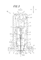
- FIG. 1 It is sectional drawing which shows the sensor insertion apparatus set as one Embodiment of this invention, and is a figure which shows the state before inserting a sensor and a needle member in a biological body. It is a figure which shows the state which moved the sensor and the needle member from the state shown in FIG. 1 to the position which can be inserted in a biological body. It is a figure which shows the state which moved the needle member to the position which can be extracted out of the living body from the state shown in FIG. It is a perspective view of the sensor insertion apparatus set shown in FIG. It is an expanded sectional view which expanded the sensor and the needle
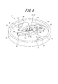
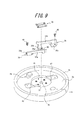
- FIG. 8 is a perspective view of the sensor and the base plate shown in FIG. 7. It is a disassembled perspective view of the base plate shown in FIG. It is a figure which shows the upper surface of a baseplate in the state with which the sensor insertion apparatus is mounted
- FIG. 1 to 3 are cross-sectional views showing the configuration of a sensor insertion device set 100 as an embodiment of the sensor insertion device set according to the present invention.
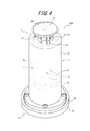
- FIG. 4 is a perspective view of the sensor insertion device set 100.
- the sensor insertion device 100 includes a sensor insertion device 1 and a base plate 2 as an embodiment of a base plate according to the present invention, which is detachably attached to one end side of the sensor insertion device 1. .
- the sensor insertion device set 100 operates the sensor insertion device 1 in a state where the base plate 2 is placed on or pressed against the living body surface, whereby the sensor 50 is placed on the lower surface of the base plate 2 (the lower side in FIGS. 1 to 4). From the side surface) into the living body.
- the sensor insertion device 1 in the sensor insertion device set 100 will be described. As shown in FIGS. 1 to 4, the sensor insertion device 1 according to the present embodiment inserts a sensor 50 capable of detecting biological information from body fluid into a living body.
- the sensor insertion device 1 includes a housing 3, a needle member 4, a first biasing member 5, a second biasing member 6, a movable member 7, and an operation member 8.
- FIGS. 1 and 4 are views showing the sensor insertion device 1 and the sensor insertion device set 100 in a state before the sensor 50 and the needle member 4 are inserted into the living body
- FIG. It is a figure which shows the sensor insertion apparatus 1 and the sensor insertion apparatus set 100 in the state which moved the needle member 4 to the position which can be inserted in a biological body
- FIG. 3 is a view showing the sensor insertion device 1 and the sensor insertion device set 100 in a state where the needle member 4 is moved to a position where it can be removed from the living body after the sensor 50 is placed in the living body.
- the housing 3 is provided on a cylindrical portion 3a that divides a substantially cylindrical hollow portion, and on one end side (the lower side in FIGS. 1 to 4) of the cylindrical portion 3a.
- a bottom plate portion 3b and a top plate portion 3c provided on the other end side (upper side in FIGS. 1 to 4) of the cylindrical portion 3a are provided.
- the bottom plate portion 3b is located on one end side of the hollow portion defined by the cylindrical portion 3a, and a through hole 9 is formed through which a needle portion 11 described later of the needle member 4 can move.
- the top plate part 3c is located on the other end side of the hollow part defined by the cylindrical part 3a, and a through hole 10 through which the movable member 7 is movable is formed.
- the bottom plate portion 3b of the housing 3 is fitted into a cylindrical tube portion 7a of the movable member 7 described later, and engages with a deformation portion 7c described later as an unlocking portion that deforms the deformation portion 7c radially outward.
- the engaging portion 60 is provided. More specifically, the engaging portion 60 of the present embodiment is a columnar protruding portion 60a formed on the upper surface of the bottom plate portion 3b.
- the bottom plate portion 3b of the housing 3 changes the engagement relationship with a pair of leaf spring portions 32 of the base plate 2 to be described later in conjunction with the operation of rotating relative to the base plate 2, and a pair of A cam portion 61 capable of changing the amount of elastic deformation of the leaf spring portion 32 is provided.
- the cam portion 61 of the present embodiment is an elliptical columnar protruding portion 61a formed on the lower surface of the bottom plate portion 3b.
- the cylindrical portion 3a and the top plate portion 3c of the housing 3 of the present embodiment are configured by a cylindrical housing body, and the bottom plate portion 3b of the present embodiment is formed by a bottom plate member that is attached and fixed to the housing body. It is configured.
- the material of the housing main body and the bottom plate member constituting the housing 3 include a resin material.
- the resin material include ABS resin, AS resin, polyethylene, polypropylene, polystyrene, polyvinyl chloride, polyvinylidene chloride resin, polyphenylene oxide, thermoplastic polyurethane, polymethylene methacrylate, polyoxyethylene, fluororesin, polycarbonate, and polyamide.
- thermoplastic resins used in injection molding such as acetal resin, acrylic resin, and polyethylene terephthalate, and thermosetting resins such as phenol resin, epoxy resin, silicone resin, and unsaturated polyester.
- needle member 4 As shown in FIGS. 1 to 4, the needle member 4 is positioned on the proximal end side of the needle portion 11 inserted into the living body together with the sensor 50, and as a second urging member 6 described later. A connecting portion 12 connected to the return spring 6a, and a locked portion 13 locked to a projection 18 as a locking portion of the movable member 7 described later, and the insertion direction of the needle portion 11 A and the needle part 11 can move in the housing 3 in the extraction direction B in which the needle part 11 is extracted from the living body.
- the insertion direction A of the needle part 11 means a direction from the proximal end of the needle part 11 toward the distal end in the extending direction of the needle part 11, and is downward in FIGS.
- the extraction direction B of the needle portion 11 means a direction from the distal end to the proximal end of the needle portion 11 in the extending direction of the needle portion 11, and is upward in FIGS.
- the extending direction of the needle part 11 is the same direction as the central axis direction of the needle part 11 in the present embodiment.
- the insertion direction A may be simply referred to as “down”
- the removal direction B may be simply referred to as “up”.
- the needle portion 11 of the present embodiment has a cylindrical outer shape that defines a hollow portion, and can accommodate the sensor 50 in the hollow portion.
- the needle part 11 is inserted into the living body in a state where the sensor 50 is accommodated in the hollow part, and after the sensor 50 is placed in the living body, the needle part 11 is removed from the living body.
- the needle part 11 of this embodiment is comprised with the hollow cylindrical needle.
- the material of the hollow cylindrical needle constituting the needle part 11 for example, a metal material such as stainless steel, aluminum, aluminum alloy, titanium, titanium alloy or the like can be used. Further, a sharp blade edge is formed at the tip of the needle portion 11.
- the connecting portion 12 of this embodiment has a substantially cylindrical shape with a through hole 14 formed therein, and a spiral groove in which a return spring 6a as the second urging member 6 is locked is formed on the outer surface thereof. Has been.
- the to-be-latched part 13 of this embodiment is a flange part which protrudes toward a radial direction outer side from the lower end part of the cylindrical connection part 12, and the outer edge part of this flange part is the latching of the movable member 7.
- the needle member 4 is locked with respect to the movable member 7 by being engaged with and hooked with the protruding portion 18 as a portion. Details of this will be described later.
- the hollow cylindrical needle which comprises the needle part 11 is being fixed, and the connection part 12 and the to-be-latched part 13 of this embodiment are comprised by the needle support member which supports a hollow cylindrical needle.
- the needle support member and the hollow cylindrical needle are fitted so that the inner peripheral surface defining the through hole 14 of the connecting portion 12 is in close contact with the outer peripheral surface of the proximal end portion of the hollow cylindrical needle,
- the hollow cylindrical needle is fixed to the needle support member.
- the needle member is not limited to the one constituted by the hollow cylindrical needle and the needle support member like the needle member 4 of the present embodiment.
- the needle portion, the connection portion, and the locked portion may be a single member. It is also possible to integrally form the members. Furthermore, you may make it comprise a needle part, a connection part, and a to-be-latched part by three or more members.
- a resin material that can be used for the housing 3 described above, a metal material that can be used for the needle portion 11 described above, or the like is used. It is possible.
- the first urging member 5 urges the needle member 4 in the insertion direction A to move the needle member 4 to a first position where the needle portion 11 can be inserted into the living body (see FIG. 2). it can. Further, the second urging member 6 urges the needle member 4 in the removal direction B so that the needle part 11 that has reached the first position (see FIG. 2) can be removed from the living body. It can be moved to the second position (see FIG. 3).
- the first urging member 5 and the second urging member 6 of the present embodiment are both elastic members (hereinafter, the elastic member as the first urging member 5 is referred to as “first elastic member”, The elastic member as the second urging member 6 is referred to as “second elastic member”.)
- springs are used as the first elastic member and the second elastic member.
- the spring as the first elastic member is simply referred to as “fire spring 5a”
- the spring as the second elastic member is simply referred to as “return spring 6a”.
- coil springs are used as the firing spring 5a and the return spring 6a.
- the first elastic member as the first urging member 5 and the second elastic member as the second urging member 6 of the present embodiment are arranged in series in the insertion direction A (or removal direction B).
- the movement of the needle member 4 in the insertion direction A is caused by the urging force of the second urging member 6 (in this embodiment, the elastic force (restoring force) of the return spring 6a as the second elastic member). )) Is not involved, and is performed by the urging force of the first urging member 5 (in this embodiment, the elastic force (restoring force) of the firing spring 5a as the first elastic member).
- the movement of the needle member 4 in the removal direction B see FIGS.
- the sensor insertion device 1 includes a switching mechanism in order to realize such an operation. The switching mechanism will be described later.
- the movable member 7 is movable in the insertion direction A in the housing 3 by the urging force of the first urging member 5 (in this embodiment, the elastic force of the compression spring 5a that is compressed and deformed). Specifically, the movable member 7 engages with the housing 3 in a state in which the firing spring 5a is compressed and deformed to a predetermined length, and a locking claw portion as a locking portion that can maintain the position of the movable member 7 with respect to the housing 3. 15 and a receiving portion 16 that abuts against the firing spring 5a as the first biasing member 5 and is pressed in the insertion direction A.
- a firing spring 5a is disposed between the movable member 7 and the top plate portion 3c of the housing 3, and the movable member 7 is resisted against the elastic force of the firing spring 5a.
- the firing spring 5a By moving the inside of the housing 3 in the removal direction B, the firing spring 5a can be compressed and deformed. Then, with the firing spring 5 a being compressed and deformed between the movable member 7 and the housing 3, the movable member 7 is moved by engaging the claw 21 of the locking claw portion 15 with the top plate portion 3 c of the housing 3. It can be locked to the housing 3 (see FIG. 1).
- the movable member 7 is locked in a state in which the first biasing member 5 holds energy for moving the movable member 7 in the insertion direction A (in this embodiment, the restoring force energy of the compression spring 5a that is compressed and deformed).
- the claw portion 15 is engaged with the housing 3.
- the needle member 4 is connected to the movable member 7 via a return spring 6a as the second urging member 6, and the movable member 7 has an elastic force of the return spring 6a that is extended and deformed to a predetermined length.
- the inside of the housing 3 can be moved in the insertion direction A by the elastic force of the firing spring 5a while maintaining the state of acting on the needle member 4.
- the movable member 7 has a connecting portion 17 connected to the upper end portion of the return spring 6a and a lower end portion of the return spring 6a in a state where the return spring 6a is extended and deformed to a predetermined length.
- a protrusion 18 as a locking portion capable of locking the connected needle member 4.
- the return spring 6 a is connected to the connection portion 12 of the needle member 4 and the connection portion 17 of the movable member 7 and is not connected to the housing 3. Therefore, the movable member 7 can move in the insertion direction A by the elastic force of the firing spring 5a while maintaining the state in which the return spring 6a is extended and deformed to a predetermined length by the protrusion 18.
- the movable member 7 is moved in the insertion direction A by the urging force of the first urging member 5 (in this embodiment, the elastic force of the firing spring 5a), and the needle member 4 is moved to the first position (FIG. 2), the locking state of the needle member 4 by the protrusion 18 is released by the engaging portion 60 as the locking releasing portion of the housing 3.
- the needle member 4 moves in the removal direction B by the urging force of the second urging member 6 (in this embodiment, the elastic force of the return spring 6a), and moves to the second position (see FIG. 3).
- the movable member 7 includes a linear rod portion 19 inserted into the needle portion 11 from the proximal end side of the needle portion 11 through the through hole 14 of the connection portion 12 of the needle member 4.
- the rod portion 19 is inserted into the needle portion 11 when the needle portion 11 and the sensor 50 in the needle portion 11 are inserted into the living body and then the needle portion 11 is removed while the sensor 50 is left in the living body.
- the sensor 50 is pressed in the insertion direction A. Thereby, it can prevent that the sensor 50 is extracted with the needle part 11.
- the movable member 7 of the present embodiment is provided with a cylindrical tube portion 7a surrounding the return spring 6a serving as the needle member 4 and the second urging member 6, and projecting radially outward from one lower end of the tube portion 7a.
- the flange portion 7b and the deformed portion located at the end portion in the insertion direction A of the cylindrical portion 7a, sandwiched between the notches 20 in the circumferential direction D of the cylindrical portion 7a, and elastically deformable radially outward of the cylindrical portion 7a A leaf spring portion as 7c (see FIG.
- a locking claw portion 15 having a claw 21 that engages with the top plate portion 3c, a receiving portion 16 that protrudes radially outward from the outer wall of the cylindrical portion 7a, and abuts against the firing spring 5a, and a top plate portion 7d
- a connection portion 17 provided on the outer surface with a spiral groove for locking the return spring 6a.
- the protrusion 18 as the locking portion described above is formed on the inner wall of the deformable portion 7c, as shown in FIGS. 1 to 3, and toward the hollow portion defined by the cylindrical portion 7a of the movable member 7. It protrudes. Therefore, the deforming portion 7c of the movable member 7 is an engagement formed on the bottom plate portion 3b located at the end portion in the insertion direction A of the housing 3 when the needle member 4 reaches the first position (see FIG. 2). It engages with a columnar protrusion 60a as the joining portion 60 and elastically deforms so as to expand outward in the radial direction of the cylindrical portion 7a.
- the protrusion 18 formed on the inner wall of the deformable portion 7c also moves outward in the radial direction, and the protrusion 18 as the locking portion of the movable member 7 and the flange portion as the locked portion 13 of the needle member 4
- the needle member 4 is moved in the tubular portion 7a in the removal direction B by the elastic force of the return spring 6a (see FIG. 3).
- the outer diameter of the columnar protrusion 60a of the housing 3 is formed to be substantially equal to the inner diameter of the cylindrical portion 7a of the movable member 7, and the protruding portion 60a is formed on the inner wall of the deformable portion 7c.
- a protrusion 22 is formed that converts the pressing force in the removal direction B received from the protruding portion 60a into the pressing force on the radially outer side of the cylindrical portion 7a while sliding on the outer wall of the protruding portion 60a.
- the lower surface 22a of the protrusion 22 is inclined with respect to the central axis O so as to approach the central axis O of the cylindrical portion 7a (in the present embodiment, the same as the central axis of the needle portion 11) as it proceeds in the extraction direction B.
- the outer peripheral surface of the projecting portion 60a slides on the lower surface 22a of the projection 22 and elastically deforms the leaf spring portion as the deformable portion 7c radially outward (see FIG. 2 and the like).
- the movement of the movable member 7 due to the elastic force of the firing spring 5 a is caused by the sliding of the outer peripheral surface of the flange portion 7 b and the receiving portion 16 of the movable member 7 with the inner peripheral surface of the cylindrical portion 3 a of the housing 3. It is configured to be guided to A. Further, as shown in FIGS. 1 to 3, the rod portion 19 extends in the insertion direction A from the connecting portion 17 with the periphery surrounded by the return spring 6a, and the tip portion thereof is a needle member. 4 to the needle portion 11 through the connection portion 12.
- the cylindrical portion 7a, the flange portion 7b, the deforming portion 7c, the top plate portion 7d, the locking claw portion 15 and the receiving portion 16 are configured by a single cylindrical body integrally formed.
- the connection part 17 in the movable member 7 of this embodiment is comprised by the connection member fastened by fastening means, such as a volt
- the rod portion 19 in the movable member 7 of the present embodiment is configured by a rod member whose base end portion is fixed to the connection member constituting the connection portion 17.
- the connecting member constituting the connecting portion 17 has a cylindrical portion in which a spiral groove capable of engaging the return spring 6 a is formed on the outer peripheral surface, and the rod member constituting the rod portion 19.
- the base end portion of the connecting member is fixed to the connecting member in a state of being inserted into the cylindrical portion of the connecting member.
- the above-described portion of the movable member is not limited to the one configured by the cylinder, the connecting member, and the rod member as in the present embodiment.
- all the portions of the above-described movable member are one or two members. It is also possible to comprise by 4 members or more.
- the above-described cylindrical body can be formed by bonding resin molded product parts that are equally divided into three in the circumferential direction of the cylindrical portion 7a using bonding means such as adhesion or welding. By setting it as such a manufacturing method, it can suppress that a metal mold becomes complicated.
- the three latching claw parts 15 are provided, it is not restricted to this number, It is good also as one or two, and good also as four or more.
- the shape and position of the locking claw 15 are not limited to the configuration of the present embodiment, and can be changed as appropriate.
- the number, position, and shape of the leaf spring portions as the deforming portion 7c are not limited to the configuration of the present embodiment, and are appropriately determined according to the number, position, shape, and the like of the engaging portions that deform the deforming portion. It is possible to change.
- the resin material that can be used for the housing 3 described above and the needle portion 11 described above.
- a metal material etc. can be used.
- the cylindrical body is preferably molded from a resin material usable for the housing 3 described above, and the connecting member and the rod member are preferably molded from a metal material usable for the needle portion 11 described above.
- the operation member 8 of the present embodiment is formed on a circular plate-like push plate portion 23 operated by a user such as a patient or a medical worker, and on the lower surface of the push plate portion 23.
- a pressing portion 26 as an unlocking portion that is formed and is capable of releasing the locking state of the movable member 7 with respect to the housing 3 by pressing and deforming the locking claw portion 15 of the movable member 7.
- claw 24 of the projection part 25 can be engaged with the lower surface of the top-plate part 3c of the housing 3 so that the operation member 8 may not fall out in the extraction direction B, and thereby the fall off of the operation member 8 is suppressed.
- the pressing portion 26 has a tapered portion 27 that is inclined with respect to the central axis O so as to approach the central axis O of the cylindrical portion 7a of the movable member 7 as it proceeds in the insertion direction A.
- the push plate portion 23 moves in the insertion direction A together with the push plate portion 23 through the through hole 10 of the top plate portion 3c.
- the taper portion 27 of the pressing portion 26 presses the locking claw portion 15 of the movable member 7 outward in the radial direction of the cylindrical portion 7a.
- the latching claw part 15 is deformed radially outward, the engagement with the top plate part 3c of the housing 3 is released, and as a result, the latched state of the movable member 7 with respect to the housing 3 is released.
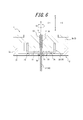
- [Sensor 50 attached to sensor insertion device 1] 5 is an enlarged cross-sectional view of the vicinity of the needle portion 11 and the sensor 50 in the sensor insertion device set 100 shown in FIG. 2, and FIG. 6 shows the needle portion in the sensor insertion device set 100 shown in FIG. 11 and an enlarged cross-sectional view in which the vicinity of a sensor 50 is enlarged.
- the sensor 50 protrudes downward through the insertion hole 70 of the base plate 2 while being accommodated in the hollow portion of the needle portion 11 constituted by a hollow cylindrical needle. Therefore, the lower surface of the base plate 2 of the sensor insertion device set 100 in the state shown in FIG. 1 is placed or pressed on the surface of the living body (skin), and the above-described firing spring 5a is activated by operating the sensor insertion device 1 from that state. By doing so, the sensor 50 and the needle part 11 can be inserted into the living body (see FIGS. 2 and 5). 2 and 5 show a state in which the needle member 4 is in the first position.
- a rubber member 71 as a septum capable of penetrating and removing the needle portion 11 is fitted into the insertion hole 70 of the base plate 2 in the present embodiment.
- the sensor 50 includes a detection unit (not shown) that is placed in the living body and capable of detecting biological information, and an optical fiber 51 that is attached to the tip of the detection unit and placed in and out of the living body.
- the needle part 11 is inserted into the living body in a state where both the detection part and the optical fiber 51 are accommodated in the hollow part of the needle part 11.
- the needle member 4 starts to move in the removal direction B by the elastic force of the return spring 6a from the state shown in FIG.
- the needle portion 11 moves in the removal direction B
- the sensor portion 50 does not move in the removal direction B when the rod portion 19 presses the sensor 50. Therefore, the sensor 50 can be placed at a predetermined depth in the living body.
- the sensor insertion device 1 is removed in a state where the base plate 2 is indwelled with the sensor 50 on the living body side. Accordingly, the proximal end side of the optical fiber 51 of the indwelled sensor 50 extending from the living body is obtained from the detection unit according to the amount of the irradiation unit and the analyte that irradiates the detection unit with excitation light. It is possible to connect an optical detection unit provided with a light receiving unit that receives the fluorescent light, and a processing device including an optical detection unit and a processing unit that processes a signal obtained from the optical detection unit.
- the optical fiber 51 constitutes a transmission path for transmitting the biological information detected by the detection unit to the processing device.
- the processing device can be appropriately designed according to the purpose and usage, such as a memory for storing biological information, a transmitter for transmitting biological information to an external device, and a display monitor for displaying biological information.
- the sensor 50 is shown in the needle portion 11 of the needle member 4. It is not a component of the device 1 but a disposable item that can be used only once and is detachably attached to the sensor insertion device 1. However, it is also possible to configure the entire sensor insertion device including the sensor as a disposable item by using the sensor as one component of the sensor insertion device.
- the needle member 4 in this embodiment is a structure which cannot be attached or detached with respect to the sensor insertion apparatus 1, it can also be set as the attachment / detachment unit which makes a needle member removable with respect to a sensor insertion apparatus, and can be disposable.
- the senor 50 is provided with an optical fiber.
- the sensor 50 is connected to a detection unit placed in the living body and extends to the outside of the living body, and a base end portion of the lead wire. You may use a sensor provided with the electrical connection part with the provided processing apparatus.
- the needle portion 11 of the needle member 4 has a cylindrical outer shape that defines the hollow portion. What you have can be used.
- the needle portion 11 having such a cylindrical outer shape is manufactured in comparison with a U-shaped needle having a U-shaped cross section in which a gap is formed in order to extend the electrical connection portion to the outside of the needle portion. Therefore, it is advantageous that a needle portion having a circular cross section as in the present embodiment can be adopted.
- the sensor insertion device 1 of the present embodiment has a biasing force of the first biasing member 5 (in this embodiment, the firing spring 5a compressed and deformed). From the movement of the needle member 4 in the insertion direction A by the restoring force) of the needle member 4 due to the biasing force of the second biasing member 6 (the restoring force of the return spring 6a expanded and deformed in this embodiment). It has a switching mechanism that can be switched alternatively to movement.
- the alternative switching means that the movement to the first position when the needle member 4 is inserted and the movement to the second position when the needle member 4 is removed are different biasing members.
- the movement of the needle member 4 during insertion is performed under the influence of the restoring force of the firing spring 5a without affecting the restoring force of the return spring 6a. It means that the movement at the time of removal of the needle member 4 performed under the influence of the restoring force of the return spring 6a without being influenced by the restoring force of the firing spring 5a is switched.
- the switching mechanism of the present embodiment is configured by a protruding portion 18 as a locking portion of the movable member 7 and a columnar protruding portion 60a that is an engaging portion as an unlocking portion of the housing 3. .
- the protrusion 18 as the locking portion of the movable member 7 engages the needle member 4 while maintaining the state in which the elastic force (restoring force) of the return spring 6a that has been stretched and deformed acts on the needle member 4. It stops, and is formed in the inner wall of the deformation
- the protruding portion 60a as the unlocking portion of the housing 3 is a needle member formed by the protruding portion 18 as the locking portion of the movable member 7 when the needle member 4 reaches the first position (see FIG. 2). 4 is released, and this protrusion 60a is formed on the bottom plate 3b, and engages with the protrusion 22 of the deformable portion 7c when the needle member 4 reaches the first position.
- the deforming portion 7c is deformed radially outward.
- the needle member 4 moves in the removal direction B by the restoring force of the return spring 6a without moving the movable member 7 within the housing 3, and within the movable member 7, specifically, the cylindrical portion of the movable member 7. 7a.
- the needle member 4 moves to the second position (see FIG. 3) by the restoring force of the return spring 6a.
- the sensor 50 and the needle portion 11 by the urging force of the firing spring 5a as the first urging member 5 are obtained only by the user performing an operation of pushing down the push plate portion 23 of the operation member 8. Insertion into the living body and removal of the needle portion 11 from the living body by the biasing force of the return spring 6a as the second biasing member 6 are automatically performed in conjunction with each other without any manual operation.
- the time for which the needle part 11 exists in the living body can be shortened. Therefore, it is possible to reduce the pain that the person to be measured in which the sensor 50 is placed feels during the period from insertion to removal of the needle part 11.
- the urging force of the second urging member 6 (in this embodiment, the elastic force of the return spring 6a) when the sensor 50 and the needle portion 11 are inserted. ) Does not act to reduce the insertion speed in the insertion direction A. Further, when the needle portion 11 is removed, the urging force of the first urging member 5 (the elastic force of the firing spring 5a in this embodiment) is removed in the removal direction B. Does not act to reduce the removal speed of the. Therefore, a sensor insertion device that does not include a switching mechanism as in the present embodiment, that is, a sensor in which the elastic force of the return spring acts to reduce the insertion speed and the elastic force of the firing spring acts to reduce the removal speed. Compared to the insertion device, in the sensor insertion device 1 of the present embodiment, it is easy to realize a configuration in which the insertion speed of the sensor 50 and the needle portion 11 and the removal speed of the needle portion 11 are increased.
- the sensor insertion device set 100 includes the sensor insertion device 1 described above and the base plate 2 that is detachably attached to one end side of the sensor insertion device 1.
- 7 shows a state where the sensor insertion device 1 and the base plate 2 are separated from each other by rotating the sensor insertion device 1 and the base plate 2 relative to the state shown in FIG.
- the base plate 2 is used together with the sensor insertion device 1 when the sensor 50 is inserted and placed in the living body (see FIGS. 1 to 3). After the sensor 50 is placed in the living body, the sensor insertion device is used. 1 and is placed on the living body side together with the sensor 50 (see FIG. 7).
- the base plate 2 separated from the sensor insertion device 1 and placed on the surface of the living body (skin) is used as a support member of the processing device to which a processing device connected to the proximal end of the optical fiber 51 of the sensor 50 can be attached. Is done.
- the base plate 2 is inserted into the living body together with the sensor 50 capable of detecting biological information, and the sensor is inserted to house the needle member 11 that is removed from the living body after the distal end side of the sensor 50 is left in the living body.
- the apparatus 1 is detachably mounted.
- FIG. 8 is a perspective view showing the sensor 50 and the base plate 2 in a state of being placed on the living body side
- FIG. 9 is an exploded perspective view of the base plate 2.
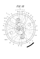
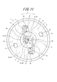
- 10 is a view showing the top surface of the base plate 2 in a state where it is attached to the sensor insertion device 1, that is, in the state shown in FIGS. 1 to 6, and FIG. That is, it is a view showing the upper surface of the base plate 2 in the state shown in FIG. 10 and 11, for convenience of explanation, the configuration of the bottom plate member constituting the bottom plate portion 3 b of the housing 3 of the sensor insertion device 1 is indicated by a broken line.
- the state in which the base plate 2 is attached to the sensor insertion device 1 means a state in which separation is not possible even if the entire sensor insertion device 1 is moved in the removal direction B with respect to the base plate 2.
- the state in which the base plate 2 can be detached from the sensor insertion device 1 means a state in which the sensor plate insertion device 1 can be separated by moving the sensor insertion device 1 in the removal direction B with respect to the base plate 2.
- the base plate 2 of the present embodiment includes the clamp portion 28 that can sandwich the sensor 50, and the mounting state and the detachable state of the base plate 2 and the sensor insertion device 1.
- the housing 3 includes a connecting portion 29 that changes the engagement relationship with the bottom plate portion 3b, a position restricting portion 30 that restricts the position of the clamp portion 28, and an adhesive portion 31 that can adhere to the surface of the living body.
- the base plate 2 of the present embodiment further includes a circular plate-like plate body 2a and a peripheral wall 2b formed continuously with the outer edge of the plate body 2a.
- the restricting portion 30 is provided at the center of the upper surface of the plate main body portion 2a, and the connecting portion 29 is provided at the outer periphery of the upper surface of the plate main body portion 2a.
- the adhesion part 31 is provided in the lower surface side of the plate main-body part 2a.
- the plate body 2a is formed with a needle portion 11 (see FIGS. 1 to 7) of the sensor insertion device 1 and an insertion hole 70 through which the sensor 50 can pass.
- the base plate 2 further includes a rubber member 71 as a septum capable of closing the insertion hole 70 and allowing the needle portion 11 and the sensor 50 to be penetrated and removed.
- the clamp unit 28 is connected to the operation of removing the sensor insertion device 1 from the base plate 2 from the state in which the sensor insertion device 1 and the base plate 2 are mounted, and then the clamp unit 28 of the sensor 50 placed on the living body side after the needle member 4 is removed. It moves so as to sandwich the proximal end side extending outside the living body. More specifically, the sensor insertion device 1 in the present embodiment can be detached from the base plate 2 by rotating relative to the base plate 2, and the clamp portion 28 in the present embodiment rotates this. In conjunction with the operation, after the needle member 4 is removed, the sensor 50 placed on the living body side moves so as to sandwich the proximal end side extending outside the living body.
- the clamp portion 28 of the present embodiment has an orthogonal direction C orthogonal to the thickness direction of the plate body portion 2a (in the insertion direction A and the extraction direction B when the base plate 2 is attached to the sensor insertion device 1).
- a pair of leaf spring portions 32 sandwiching the proximal end side of the sensor 50 by an elastic force in the same direction as the orthogonal direction) and the movement of the pair of leaf spring portions 32 in the thickness direction of the plate body portion 2a are regulated.
- a pair of leaf springs 32 are in a state where the sensor insertion device 1 and the base plate 2 are mounted (see FIG. 10) and in a removable positional relationship (see FIG.
- the shape is changed by the action of the elliptical columnar protrusion 61a as the cam portion 61 of the sensor insertion device 1.
- the operation of removing the sensor insertion device 1 from the base plate 2 from the state in which the sensor insertion device 1 and the base plate 2 are mounted in this embodiment, the sensor insertion device 1 is rotated relative to the base plate 2).
- the protruding portion 61 a as the cam portion 61 changes the engagement relationship with the pair of leaf spring portions 32 to change the amount of elastic deformation of the pair of leaf spring portions 32.
- the pair of leaf spring portions 32 are separated from each other by an elliptic columnar protrusion 61 a serving as the cam portion 61.
- the pair of leaf spring portions 32 are moved away from both sides of the long axis direction by the outer surfaces facing the long axis direction of the protruding portion 61a. Is pressed and is elastically deformed so that the facing distance M of the portion sandwiching the sensor 50 is increased. Therefore, in a state where the sensor insertion device 1 and the base plate 2 are mounted (see FIG. 10), the pair of leaf spring portions 32 do not sandwich the sensor 50.
- the opposing distance M between the pair of leaf spring portions 32 is expanded by the protruding portions 61a. Since the pair of leaf spring portions 32 do not contact the sensor 50 and the needle portion 11, the insertion operation of the needle portion 11 and the sensor 50 through the insertion hole 70 of the base plate 2 is performed as a pair of the clamp portion 28. It is not obstructed by the leaf spring part 32.
- the pair of leaf spring portions 32 are pressed by the outer surfaces facing each other in the long axis direction of the protruding portion 61a when the sensor insertion device 1 and the base plate 2 are mounted (see FIG. 10).
- the sensor insertion device 1 is rotated in one direction of the circumferential direction D with respect to the base plate 2 and the base plate 2 is moved to a position where it can be removed with respect to the sensor insertion device 1 (see FIG. 11)
- the pair of leaf spring portions 32 is released from the pressing by the protruding portion 61a and moves so as to approach each other in the orthogonal direction C by the restoring force, so that the sensor insertion device 1 and the base plate 2 are mounted (see FIG. 10), the facing distance M becomes smaller.
- the pair of leaf spring portions 32 of the clamp portion 28 can sandwich the proximal end side of the sensor 50 extending outside the living body by this restoring force.
- the optical fiber 51 of the sensor 50 is sandwiched between the pair of leaf spring portions 32.
- the sensor 50 and the base plate 2 are inserted into the sensor.
- the clamp portion 28 of the base plate 2 sandwiches the sensor 50 in conjunction with the removal operation from the sensor insertion device 1.
- the base plate 2 whose position is fixed on the surface of the living body by the adhesive portion 31 to be described later after the sensor insertion device 1 is removed holds the portion of the sensor 50 that extends outside the living body. It is possible to prevent the portion placed in the body from moving so as to be removed from the living body due to the body movement of the measurement subject.
- the pair of leaf spring portions 32 of the present embodiment includes a first leaf spring 34 and a second leaf spring 35 disposed to face the first leaf spring 34, and The 1 plate spring 34 and the 2nd plate spring 35 are attached to the upper surface of the plate main-body part 2a.
- the first leaf spring 34 is in contact with or pressed against the sensor 50 when the sensor 50 is sandwiched between the first plate spring 34 and the contact portion 36a.
- a deformable portion 37a that can change the position in C, and a fixing portion 38a that fixes one end of the deformable portion 37a to the plate main body portion 2a are provided.
- the second leaf spring 35 includes a contact portion 36b, a deformable portion 37b, and a fixed portion 38b.
- a recess 39 for receiving the sensor 50 when the sensor 50 is sandwiched is formed in the contact portions 36a and 36b.
- the concave portions 39 of the contact portions 36a and 36b have a substantially semicircular shape when the base plate 2 is viewed from the upper surface side (see FIGS. 10 and 11), and the sensor 50 includes the contact portions 36a and 36b. 36b is sandwiched between the respective concave portions 39.
- the above-mentioned facing distance M is a distance connecting points that are the bottom positions of the semicircular concave portions 39 of the contact portions 36a and 36b when the base plate 2 is viewed from the upper surface side. (See FIGS. 10 and 11).
- the deforming portion 37a is a long plate-like member having one end continuous with the contact portion 36a and the other end continuous with the fixed portion 38a.
- the position of the fixing portion 38a fixed to the plate body 2a by the portion 47 and the screw 40 as a fulcrum position one end side continuous with the contact portion 36a can be elastically deformed. Therefore, the position of the contact portion 36a in the orthogonal direction C (see FIG. 1 and the like) can be changed by elastically deforming one end side continuous with the contact portion 36a in the deformation portion 37a.
- the deforming portion 37b and the fixing portion 38b of the second leaf spring 35 are the deforming portion 37b and the fixing portion 38b of the second leaf spring 35.
- the spring pressing portion 33 restricts the pair of plate spring portions 32 from moving in the thickness direction of the plate body portion 2a, and the spring pressing portion 33 of the present embodiment is configured by a rectangular plate member. Further, the spring pressing portion 33 in the present embodiment has upper surfaces of the contact portions 36a and 36b so as to cover the upper portions of the contact portion 36a of the first plate spring 34 and the contact portion 36b of the second plate spring 35, respectively. Is attached and fixed to the upper surface of the plate body 2a. Specifically, the spring pressing portion 33 is formed on the upper surface of the plate main body portion 2a in a fixing hole formed in the spring pressing portion 33 with the contact portions 36a and 36b interposed between the spring pressing portion 33 and the plate main body portion 2a. The fixed projection 46 is fixed to the plate body 2a by closely fitting (see FIGS. 8 and 9).
- plate spring part 32 and the spring pressing part 33 are accommodated is formed in the upper surface center of the plate main-body part 2a of this embodiment.
- the connecting portion 29 moves the sensor insertion device 1 in the removal direction B with respect to the base plate 2 in the bottom plate portion 3b of the sensor insertion device 1 ( It regulates by engaging (refer FIG. 1 etc.). Further, the connecting portion 29 moves the sensor insertion device 1 in the removal direction B with respect to the base plate 2 when the base plate 2 is in a position where the base plate 2 can be detached from the sensor insertion device 1 (see FIG. 11). This is allowed by not engaging with the bottom plate portion 3b.
- the connecting portion 29 of the present embodiment is located above the upper surface of the plate body 2a (the same as the removal direction B when the base plate 2 is attached to the sensor insertion device 1).
- the body portion 41 and the distal end portion 42 are formed on the bottom surface of the flange portion 62 of the housing main body, which is formed with the connecting hole 43 formed in the bottom plate member constituting the bottom plate portion 3b, and the bottom plate portion 3b.
- the sensor insertion device 1 and the base plate 2 can be switched between a mounting state and a detachable state by moving in a recess 44 (see FIG. 1 and the like) communicating with the terminal 43.
- connection hole 43 formed in the bottom plate member constituting the bottom plate portion 3b has a long shape in the circumferential direction D when the bottom plate member is viewed from the upper surface side (FIGS. 10 and 10). 11), at one end in the circumferential direction D, an attachment / detachment opening 43a into which the body 41 and the tip 42 are inserted and removed when the base plate 2 is attached / detached is provided.
- the detachable opening 43a has a larger width (the length in the radial direction in FIGS. 10 and 11) than the other part of the connecting hole 43. As shown in FIGS.
- the length of the connecting portion 29 in the radial direction of the base plate 2 (same as the length of the tip portion 42 in this embodiment) is as follows.
- the width of the connecting hole 43 is smaller than the width of the attaching / detaching opening 43a and larger than the width of the connecting hole 43 other than the attaching / detaching opening 43a.
- the concave portion 44 formed in the flange portion 62 covers the upper portion of the connecting hole 43 of the bottom plate member, and has a shape that is long in the circumferential direction D like the connecting hole 43. .
- the recess 44 is substantially equal in width to the detachable opening 43a regardless of the position in the circumferential direction D, that is, larger than the length of the connecting portion 29 in the radial direction of the base plate 2 when the base plate 2 is viewed from the upper surface side. It has a width.
- the distal end portion 42 of the connecting portion 29 of the base plate 2 is inserted into the attaching / detaching opening 43 a of the connecting hole 43. .
- tip part 42 arrives at the position of the recessed part 44, the front-end
- the body portion 41 of the connecting portion 29 moves in the circumferential direction D in the connecting hole 43. By this rotation operation, the positions in the circumferential direction D of the connecting portion 29 and the detachable opening 43a are shifted.
- this state is a state in which the base plate 2 is attached to the sensor insertion device 1 (see FIG. 10).
- this state is a state in which the base plate 2 is in a position where it can be detached from the sensor insertion device 1 (see FIG. 11).
- the sensor insertion device 1 and the base plate 2 are separated after the sensor 50 is placed in the living body, the sensor insertion device 1 is rotated with respect to the base plate 2 while the base plate 2 is pressed against the surface of the living body. By operation, the sensor insertion device 1 is moved to a position where it can be detached from the base plate 2. Therefore, according to the sensor insertion device set 100 of the present embodiment, a patient or a medical worker presses the base plate 2 against the living body surface, rotates the sensor insertion device 1 with respect to the base plate 2, and the sensor insertion device 1. A series of operations of moving in the extraction direction B for separating the sensor from the base plate 2 can be performed by the operation of one hand holding the sensor insertion device 1.
- one of the sensor insertion device 1 and the base plate 2 is rotated relative to the other in the circumferential direction D, so that the attachment / detachment opening 43a of the sensor insertion device 1 and the connection portion 29 of the base plate 2 are circumferential.
- the sensor insertion device 1 and the base plate 2 can be switched between the mounted state (see FIG. 10) and the removable state (see FIG. 11).
- the engagement relationship between the pair of leaf spring portions 32 and the cam portion 61 in this embodiment, the protruding portion 61a
- the sensor insertion device 1 and the base plate 2 are changed.
- the sensor 50 can be held by the elastic force of the pair of leaf spring portions 32.
- the sensor insertion device 1 is rotated to move away from the base plate 2 in the removal direction B.
- the pair of leaf spring portions 32 in the clamp portion 28 of the base plate 2 that moves in conjunction with the rotation operation sandwich the sensor 50 by elastic force.
- the sensor insertion device and the base plate are mounted in conjunction with the specific rotation of the sensor insertion device and the base plate, and the sensor is sandwiched in conjunction with the rotation operation for removing the base plate from the sensor insertion device.
- the specific configuration of the clamp portion is not limited to the configuration of the present embodiment.
- the screw insertion may be used for mounting and removing the sensor insertion device and the base plate, and the clamp portion may be used from the sensor insertion device. It can be realized by various configurations, such as using a moving member that moves without being deformed in conjunction with a turning operation for removing the base plate and sandwiches the sensor. In the present embodiment, as an operation for separating the sensor insertion device 1 from the base plate 2, an operation of rotating one of the sensor insertion device 1 and the base plate 2 with respect to the other is performed.
- the clamp unit 28 may be a clamp unit that clamps the sensor in conjunction with an operation of moving the sensor insertion device in the removal direction with respect to the base plate.
- the operation distance for switching the mounting state and the detachable state of the sensor insertion device and the base plate (in this embodiment, the circumference of the connecting hole 43) by using a clamp portion that interlocks with the rotating operation as in this embodiment. Since the length in the direction D) does not have to be secured in the thickness direction of the base plate, the base plate has a reduced thickness in the removal direction compared to the case where the sensor insertion device is moved in the removal direction. It becomes easy to design.
- the user does not touch the tip of the needle portion 11.
- the tip of the needle portion 11 is housed in the housing 3 so as not to protrude outward from the bottom plate portion 3b of the housing 3 (see FIGS. 3, 6, and 7). .
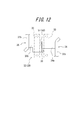
- FIG. 12 is an enlarged view illustrating the central portion of the base plate 2 shown in FIG. 11 in an enlarged manner.
- the above-described second leaf spring 35 has a larger spring constant than the first leaf spring 34.
- a positioning pin serving as a position restricting portion 30 that restricts the position of 35 is provided. 8 to 11, the positioning pins are omitted for convenience of explanation.
- the spring pressing portion 33 is indicated by a broken line for convenience of explanation.
- the positioning pin as the position restricting portion 30 is provided so as to protrude from the upper surface of the plate body 2a, and when the sensor insertion device 1 and the base plate 2 are removed, that is, the sensor insertion device 1 and the base plate 2 are attached.
- the contact portion 36b of the second leaf spring 35 moves so as to sandwich the sensor 50.
- the further movement of the contact portion 36b of the second leaf spring 35 is restricted. That is, the second leaf spring 35 having a spring constant larger than that of the first leaf spring 34 is positioned by the positioning pin, and the first leaf spring 34 is pressed against the second leaf spring 35 positioned by the positioning pin.
- the sensor 50 is sandwiched between the first leaf spring 34 and the second leaf spring 35.
- the spring constant of the second leaf spring 35 is made larger than the spring constant of the first leaf spring 34, and the second leaf spring 35 is brought into contact with the position restricting portion 30 to make the second leaf spring. 35 is positioned, the sensor 50 sandwiched between the first leaf spring 34 and the second leaf spring 35 is in the contact portion 36b of the second leaf spring 35 in a state of being in contact with the position restricting portion 30. At the position of the recess 39 (see FIG. 9), the contact portion 36a of the first leaf spring 34 and the contact portion 36b of the second leaf spring 35 can be sandwiched.
- the second leaf spring 35 that contacts the position restricting portion 30 functions as the positioning of the sensor 50 to be sandwiched, variation in the sandwiching position of the sensor 50 on the base plate 2 can be suppressed.
- the signal fluctuates due to a slight movement of the optical fiber placed in the living body. Therefore, accurate biological information can be obtained by suppressing variations in the sandwiched position of the sensor.
- the adhesive portion 31 adheres to the living body surface when the sensor 50 is inserted by the sensor insertion device set 100 and when it is separated from the sensor insertion device 1 and placed on the living body surface, and the position of the base plate 2 on the body surface Is provided on the surface of the base plate 2 that faces the surface of the living body, that is, the lower surface.
- the adhesion part 31 of this embodiment is comprised by the double-sided adhesive sheet provided with the 1st adhesion layer adhere
- the adhesive portion 31 can be configured by various means such as a configuration in which an adhesive is provided at a position other than the insertion hole 70 on the lower surface of the base plate 2 to form the adhesive portion 31.
- the adhesive portion 31 is provided on the entire lower surface of the base plate 2 and penetrates at the position of the insertion hole 70 when the sensor 50 and the needle portion 11 are inserted by the sensor insertion device set 100. It is also possible to adopt a configuration in which the lower surface of the base plate 2 is attached to a portion other than the insertion hole 70.
- adhesives such as a rubber adhesive, an acrylic adhesive, a silicone adhesive, can be used, for example.
- portions of the base plate 2 other than the adhesive portion 31 can be formed of the same material as that of the housing 3 of the sensor insertion device 1 described above.
- the sensor insertion device set 100 of the present embodiment is inserted into the living body together with the sensor 50 capable of detecting biological information, and the needle that is removed from the living body after the distal end side of the sensor 50 is placed in the living body.
- a sensor insertion device 1 that accommodates the member 4 and a base plate 2 that is detachably attached to the sensor insertion device 1 are provided.
- the base plate 2 is inserted into the sensor. It is separated from the device 1 and placed on the living body side together with the sensor 50.
- a processing device capable of processing the biological information of the measurement subject detected by the sensor 50 is attached to the base plate 2 placed on the surface of the living body. For example, a change in blood glucose level of a diabetic patient over time is measured. It becomes possible to monitor over a predetermined period based on the biological information of the measurer.
- the sensor insertion device set and the base plate according to the present invention are not limited to the configuration of the above-described embodiment, and can be realized by various configurations without departing from the content described in the claims. It is.
- the movable member 7 is used as a plunger that moves due to the elastic force of the firing spring 5 a when the sensor 50 and the needle part 11 are inserted into the living body, but due to the biasing force of the first biasing member. It is good also as a structure which does not move at the time of insertion of a sensor and a needle part, but moves at the time of extraction of the needle part by the urging
- the present invention relates to a sensor insertion device set and a base plate including a sensor insertion device and a base plate for inserting a sensor for detecting biological information of a living body such as a patient into the living body.
- sensor insertion device 2 base plate 2a: plate main body portion 2b: peripheral wall portion 3: housing 3a: tube portion 3b: bottom plate portion 3c: top plate portion 4: needle member 5: first biasing member 5a: firing spring (first 1 elastic member) 6: Second urging member 6a: Return spring (second elastic member) 7: Movable member 7a: Tube portion 7b: Flange portion 7c: Deformation portion 7d: Top plate portion 8: Operation member 9: Through hole in bottom plate portion 10: Through hole in top plate portion 11: Needle portion 12: Connection portion 13: Locked portion 14: Connection portion through hole 15: Locking claw portion (locking portion) 16: Receiving part 17: Connection part 18: Projection part (locking part) 19: Rod part 20: Notch 21: Claw 22: Projection 22a: Lower surface 23 of projection: Push plate part 24: Claw 25: Projection part 26: Pressing part 27: Taper part 28: Clamp part 29: Connecting part 30: Position Restricting part 31: Adhesive part 32: A
Abstract
The sensor insertion device set pertaining to the present invention is provided with: a sensor insertion device provided with a needle member inserted in a living body together with a sensor capable of detecting biological information, the distal end of the sensor being implanted in the living body, and the needle member subsequently being removed from the living body; and a base plate removably installed at one end of the sensor insertion device; the base plate being provided with a clamp part for moving so as to pinch a proximal-end side of the sensor extending outside the living body after removal of the needle member, the clamp part moving in conjunction with an operation for removing the sensor insertion device from the base plate.
Description
本発明は、患者等の生体の生体情報を検出するセンサを生体内に挿入するセンサ挿入装置とベースプレートとを備えるセンサ挿入装置セット及びベースプレートに関する。
The present invention relates to a sensor insertion device set and a base plate including a sensor insertion device and a base plate for inserting a sensor for detecting biological information of a living body such as a patient into the living body.
従来、患者などの被測定者の体内にセンサを挿入あるいは埋め込み、患者の血液又は体液中のアナライト(例えば、グルコースやpH、コレステロール、たんぱく質等)を該センサによって検出することが行われている。この場合、患者の皮膚を貫通してセンサを迅速且つ容易に配置するためにセンサ挿入装置が使用される(特許文献1参照)。
Conventionally, a sensor is inserted or implanted in the body of a subject such as a patient, and an analyte (eg, glucose, pH, cholesterol, protein, etc.) in the blood or body fluid of the patient is detected by the sensor. . In this case, a sensor insertion device is used to quickly and easily place the sensor through the patient's skin (see Patent Document 1).
特許文献1に記載された検体測定システム(センサ挿入装置セット)は、アプリケータ(センサ挿入装置)と、生体表面側にセンサと共に留置される取付けユニットと、を備えている。また、特許文献1のアプリケータは、センサとともに挿入される挿入針と、該センサ及び挿入針を移動させて穿刺させるプランジャサブアッセンブリ(移動機構)と、を備えている。
The specimen measurement system (sensor insertion device set) described in Patent Document 1 includes an applicator (sensor insertion device) and an attachment unit that is placed together with the sensor on the surface of the living body. Moreover, the applicator of Patent Document 1 includes an insertion needle that is inserted together with a sensor, and a plunger subassembly (movement mechanism) that moves the sensor and the insertion needle to puncture.
ところで、生体内にセンサを留置した後に、被測定者の体動等によって、センサが生体外へ抜去される方向に移動してしまうことがあり、かかる場合には、正確な生体情報を検出できなくなるおそれがある。
By the way, after placing the sensor in the living body, the sensor may move in the direction of being removed from the living body due to the body movement of the measurement subject. In such a case, accurate biological information can be detected. There is a risk of disappearing.
そこで、本発明の目的は、生体内に留置されたセンサが体動によっても抜去方向に移動し難くすることが可能なセンサ挿入装置セット及びベースプレートを提供することである。
Therefore, an object of the present invention is to provide a sensor insertion device set and a base plate that can make it difficult for a sensor placed in a living body to move in the removal direction even by body movement.
本発明の第1の態様としてのセンサ挿入装置セットは、生体情報を検出可能なセンサと共に生体内に挿入され、前記センサの先端側を生体内に留置した後に生体外へと抜去される針部材を備えるセンサ挿入装置と、前記センサ挿入装置の一端側に取り外し可能に装着されたベースプレートと、を備え、前記ベースプレートは、前記センサ挿入装置を前記ベースプレートから取り外す動作に連動して、前記針部材の抜去後に前記センサの生体外に延在する基端側を挟み込むように移動するクランプ部を備えることを特徴とするものである。
The sensor insertion device set according to the first aspect of the present invention includes a needle member that is inserted into a living body together with a sensor capable of detecting biological information, and is removed from the living body after the distal end side of the sensor is placed in the living body. And a base plate that is detachably attached to one end of the sensor insertion device, the base plate interlocking with an operation of removing the sensor insertion device from the base plate, It comprises a clamp part that moves so as to sandwich the proximal end side of the sensor that extends outside the living body after removal.
本発明の1つの実施形態として、前記クランプ部は、前記センサの前記基端側を挟み込む一対の板バネ部を備え、前記センサ挿入装置は、前記ベースプレートに対して相対的に回動させることによって、前記ベースプレートから取り外し可能であり、前記回動させる動作に連動して、前記一対の板バネ部との係合関係を変化させて、前記一対の板バネ部の弾性変形量を変化させることが可能なカム部を備えることが好ましい。
As one embodiment of the present invention, the clamp portion includes a pair of leaf spring portions that sandwich the base end side of the sensor, and the sensor insertion device is rotated relative to the base plate. Detachable from the base plate, and interlocking with the pivoting operation, the engagement relationship between the pair of leaf springs is changed to change the amount of elastic deformation of the pair of leaf springs. It is preferable to provide a possible cam part.
本発明の1つの実施形態として、前記一対の板バネ部は、第1板バネと、前記第1板バネと対向して配置され、前記第1板バネよりもばね定数の大きい第2板バネと、を備え、前記ベースプレートは、前記センサ挿入装置から取り外される際に、前記第2板バネの位置を規制する位置規制部を備えることが好ましい。
As one embodiment of the present invention, the pair of leaf springs are arranged to face the first leaf spring and the first leaf spring, and have a larger spring constant than the first leaf spring. Preferably, the base plate includes a position restricting portion that restricts the position of the second leaf spring when the base plate is removed from the sensor insertion device.
本発明の1つの実施形態として、前記ベースプレートのうち生体表面と対向する面には、生体表面と粘着する粘着部が設けられていることが好ましい。
As one embodiment of the present invention, it is preferable that an adhesive portion that adheres to the living body surface is provided on the surface of the base plate that faces the living body surface.
本発明の1つの実施形態として、前記センサは、生体内に留置され、生体情報を検出可能な検出部と、前記検出部が先端部に装着され、生体内外に跨って留置される光ファイバと、を備えることが好ましい。
As one embodiment of the present invention, the sensor is indwelled in a living body and can detect living body information; and an optical fiber in which the detecting unit is attached to a distal end portion and placed in and out of the living body. Are preferably provided.
本発明の第2の態様としてのベースプレートは、生体情報を検出可能なセンサと共に生体内に挿入され、前記センサの先端側を生体内に留置した後に生体外へと抜去される針部材を収容するセンサ挿入装置に対して、着脱可能に装着されるベースプレートであって、前記センサ装置に装着されている状態から前記センサ装置に対して相対的に回動させる動作に連動して、前記針部材の抜去後に前記センサの生体外に延在する基端側を挟み込むように移動するクランプ部を備えることを特徴とするものである。
A base plate as a second aspect of the present invention accommodates a needle member that is inserted into a living body together with a sensor capable of detecting biological information, and is removed from the living body after the distal end side of the sensor is placed in the living body. A base plate that is detachably attached to the sensor insertion device, and is interlocked with an operation of rotating the needle member relative to the sensor device from a state of being attached to the sensor device. It comprises a clamp part that moves so as to sandwich the proximal end side of the sensor that extends outside the living body after removal.
本発明によれば、生体内に留置されたセンサが体動によっても抜去方向に移動し難くすることが可能なセンサ挿入装置セット及びベースプレートを提供することができる。
According to the present invention, it is possible to provide a sensor insertion device set and a base plate capable of making it difficult for a sensor placed in a living body to move in the removal direction even by body movement.
以下、本発明に係るセンサ挿入装置セット及びベースプレートの実施形態について、図1~図12を参照して説明する。なお、各図において共通の部材には、同一の符号を付している。
Hereinafter, embodiments of a sensor insertion device set and a base plate according to the present invention will be described with reference to FIGS. In addition, the same code | symbol is attached | subjected to the common member in each figure.
図1~図3は、本発明に係るセンサ挿入装置セットの1つの実施形態としてのセンサ挿入装置セット100の構成を示す断面図である。また、図4は、センサ挿入装置セット100の斜視図である。このセンサ挿入装置100は、センサ挿入装置1と、このセンサ挿入装置1の一端側に取り外し可能に装着された、本発明に係るベースプレートの1つの実施形態としてのベースプレート2と、を備えるものである。
1 to 3 are cross-sectional views showing the configuration of a sensor insertion device set 100 as an embodiment of the sensor insertion device set according to the present invention. FIG. 4 is a perspective view of the sensor insertion device set 100. The sensor insertion device 100 includes a sensor insertion device 1 and a base plate 2 as an embodiment of a base plate according to the present invention, which is detachably attached to one end side of the sensor insertion device 1. .
センサ挿入装置セット100は、ベースプレート2を生体表面上に載置した状態又は押しつけた状態で、センサ挿入装置1を操作することにより、センサ50を、ベースプレート2の下面(図1~図4における下側の面)から生体内へと挿入するものである。
The sensor insertion device set 100 operates the sensor insertion device 1 in a state where the base plate 2 is placed on or pressed against the living body surface, whereby the sensor 50 is placed on the lower surface of the base plate 2 (the lower side in FIGS. 1 to 4). From the side surface) into the living body.
<センサ挿入装置セット100>
<センサ挿入装置1>
まず、センサ挿入装置セット100におけるセンサ挿入装置1について説明する。図1~図4に示すように、本実施形態におけるセンサ挿入装置1は、体液から生体情報を検出可能なセンサ50を生体内に挿入するものである。具体的に、センサ挿入装置1は、ハウジング3と、針部材4と、第1付勢部材5と、第2付勢部材6と、可動部材7と、操作部材8と、を備えている。 <SensorInsertion Device Set 100>
<Sensor insertion device 1>
First, the sensor insertion device 1 in the sensorinsertion device set 100 will be described. As shown in FIGS. 1 to 4, the sensor insertion device 1 according to the present embodiment inserts a sensor 50 capable of detecting biological information from body fluid into a living body. Specifically, the sensor insertion device 1 includes a housing 3, a needle member 4, a first biasing member 5, a second biasing member 6, a movable member 7, and an operation member 8.
<センサ挿入装置1>
まず、センサ挿入装置セット100におけるセンサ挿入装置1について説明する。図1~図4に示すように、本実施形態におけるセンサ挿入装置1は、体液から生体情報を検出可能なセンサ50を生体内に挿入するものである。具体的に、センサ挿入装置1は、ハウジング3と、針部材4と、第1付勢部材5と、第2付勢部材6と、可動部材7と、操作部材8と、を備えている。 <Sensor
<Sensor insertion device 1>
First, the sensor insertion device 1 in the sensor
ここで、図1及び図4は、センサ50及び針部材4を生体内に挿入する前の状態にあるセンサ挿入装置1及びセンサ挿入装置セット100を示す図であり、図2は、センサ50及び針部材4を生体内に挿入可能な位置まで移動させた状態にあるセンサ挿入装置1及びセンサ挿入装置セット100を示す図である。また、図3は、センサ50を生体内に留置した後、針部材4を生体内から抜去可能な位置まで移動させた状態にあるセンサ挿入装置1及びセンサ挿入装置セット100を示す図である。
Here, FIGS. 1 and 4 are views showing the sensor insertion device 1 and the sensor insertion device set 100 in a state before the sensor 50 and the needle member 4 are inserted into the living body, and FIG. It is a figure which shows the sensor insertion apparatus 1 and the sensor insertion apparatus set 100 in the state which moved the needle member 4 to the position which can be inserted in a biological body. FIG. 3 is a view showing the sensor insertion device 1 and the sensor insertion device set 100 in a state where the needle member 4 is moved to a position where it can be removed from the living body after the sensor 50 is placed in the living body.
以下、本実施形態におけるセンサ挿入装置1の各部材及び各部材により構成される特徴部の詳細について説明する。
Hereinafter, each member of sensor insertion device 1 in this embodiment and the details of the characteristic part constituted by each member are explained.
[ハウジング3]
図1~図4に示すように、ハウジング3は、略円柱状の中空部を区画する筒部3aと、この筒部3aの一端側(図1~図4においては下側)に設けられた底板部3bと、筒部3aの他端側(図1~図4においては上側)に設けられた天板部3cと、を備えている。底板部3bは、筒部3aが区画する中空部の一端側に位置し、針部材4の後述する針部11が移動可能な貫通孔9が形成されている。また、天板部3cは、筒部3aが区画する中空部の他端側に位置し、可動部材7が移動可能な貫通孔10が形成されている。 [Housing 3]
As shown in FIGS. 1 to 4, thehousing 3 is provided on a cylindrical portion 3a that divides a substantially cylindrical hollow portion, and on one end side (the lower side in FIGS. 1 to 4) of the cylindrical portion 3a. A bottom plate portion 3b and a top plate portion 3c provided on the other end side (upper side in FIGS. 1 to 4) of the cylindrical portion 3a are provided. The bottom plate portion 3b is located on one end side of the hollow portion defined by the cylindrical portion 3a, and a through hole 9 is formed through which a needle portion 11 described later of the needle member 4 can move. Moreover, the top plate part 3c is located on the other end side of the hollow part defined by the cylindrical part 3a, and a through hole 10 through which the movable member 7 is movable is formed.
図1~図4に示すように、ハウジング3は、略円柱状の中空部を区画する筒部3aと、この筒部3aの一端側(図1~図4においては下側)に設けられた底板部3bと、筒部3aの他端側(図1~図4においては上側)に設けられた天板部3cと、を備えている。底板部3bは、筒部3aが区画する中空部の一端側に位置し、針部材4の後述する針部11が移動可能な貫通孔9が形成されている。また、天板部3cは、筒部3aが区画する中空部の他端側に位置し、可動部材7が移動可能な貫通孔10が形成されている。 [Housing 3]
As shown in FIGS. 1 to 4, the
ハウジング3の底板部3bは、後述する可動部材7の円筒状の筒部7a内に嵌り込み、後述する変形部7cと係合して変形部7cを径方向外側に変形させる係止解除部としての係合部60を備えている。より具体的に、本実施形態の係合部60とは、底板部3bの上面に形成された円柱状の突出部60aである。
The bottom plate portion 3b of the housing 3 is fitted into a cylindrical tube portion 7a of the movable member 7 described later, and engages with a deformation portion 7c described later as an unlocking portion that deforms the deformation portion 7c radially outward. The engaging portion 60 is provided. More specifically, the engaging portion 60 of the present embodiment is a columnar protruding portion 60a formed on the upper surface of the bottom plate portion 3b.
また、ハウジング3の底板部3bは、ベースプレート2に対して相対的に回動させる動作に連動して、後述するベースプレート2の一対の板バネ部32との係合関係を変化させて、一対の板バネ部32の弾性変形量を変化させることが可能なカム部61を備えている。より具体的に、本実施形態のカム部61は、底板部3bの下面に形成された楕円柱状の突出部61aである。
In addition, the bottom plate portion 3b of the housing 3 changes the engagement relationship with a pair of leaf spring portions 32 of the base plate 2 to be described later in conjunction with the operation of rotating relative to the base plate 2, and a pair of A cam portion 61 capable of changing the amount of elastic deformation of the leaf spring portion 32 is provided. More specifically, the cam portion 61 of the present embodiment is an elliptical columnar protruding portion 61a formed on the lower surface of the bottom plate portion 3b.
なお、本実施形態のハウジング3の筒部3a及び天板部3cは、筒状のハウジング本体により構成されており、本実施形態の底板部3bは、ハウジング本体に取り付けられ固定される底板部材により構成されている。ハウジング3を構成するハウジング本体及び底板部材の材料としては、例えば樹脂材料が挙げられる。この樹脂材料としては、例えば、ABS樹脂、AS樹脂、ポリエチレン、ポリプロピレン、ポリスチレン、ポリ塩化ビニル、ポリ塩化ビニリデン樹脂、ポリフェニレンオキサイド、熱可塑性ポリウレタン、ポリメチレンメタクリレート、ポリオキシエチレン、フッ素樹脂、ポリカーボネート、ポリアミド、アセタール樹脂、アクリル樹脂、ポリエチレンテレフタレート等の射出成形で用いられる熱可塑性樹脂や、フェノール樹脂、エポキシ樹脂、シリコーン樹脂、不飽和ポリエステル等の熱硬化性樹脂等が挙げられる。
The cylindrical portion 3a and the top plate portion 3c of the housing 3 of the present embodiment are configured by a cylindrical housing body, and the bottom plate portion 3b of the present embodiment is formed by a bottom plate member that is attached and fixed to the housing body. It is configured. Examples of the material of the housing main body and the bottom plate member constituting the housing 3 include a resin material. Examples of the resin material include ABS resin, AS resin, polyethylene, polypropylene, polystyrene, polyvinyl chloride, polyvinylidene chloride resin, polyphenylene oxide, thermoplastic polyurethane, polymethylene methacrylate, polyoxyethylene, fluororesin, polycarbonate, and polyamide. And thermoplastic resins used in injection molding such as acetal resin, acrylic resin, and polyethylene terephthalate, and thermosetting resins such as phenol resin, epoxy resin, silicone resin, and unsaturated polyester.
[針部材4]
図1~図4に示すように、針部材4は、センサ50と共に生体内に挿入される針部11と、この針部11の基端側に位置し、後述する第2付勢部材6としての戻しバネ6aと接続される接続部12と、後述する可動部材7の係止部としての突起部18に係止される被係止部13と、を備えており、針部11の挿入方向A及び針部11が生体内から抜去される抜去方向Bにおいてハウジング3内を移動可能である。 [Needle member 4]
As shown in FIGS. 1 to 4, theneedle member 4 is positioned on the proximal end side of the needle portion 11 inserted into the living body together with the sensor 50, and as a second urging member 6 described later. A connecting portion 12 connected to the return spring 6a, and a locked portion 13 locked to a projection 18 as a locking portion of the movable member 7 described later, and the insertion direction of the needle portion 11 A and the needle part 11 can move in the housing 3 in the extraction direction B in which the needle part 11 is extracted from the living body.
図1~図4に示すように、針部材4は、センサ50と共に生体内に挿入される針部11と、この針部11の基端側に位置し、後述する第2付勢部材6としての戻しバネ6aと接続される接続部12と、後述する可動部材7の係止部としての突起部18に係止される被係止部13と、を備えており、針部11の挿入方向A及び針部11が生体内から抜去される抜去方向Bにおいてハウジング3内を移動可能である。 [Needle member 4]
As shown in FIGS. 1 to 4, the
ここで、針部11の挿入方向Aとは、針部11の延在方向のうち針部11の基端から先端に向かう方向を意味し、図1~図4においては下方である。一方、針部11の抜去方向Bとは、針部11の延在方向のうち針部11の先端から基端に向かう方向を意味し、図1~図4においては上方である。なお、針部11の延在方向とは、本実施形態では針部11の中心軸線方向と同じ方向である。また、以下、挿入方向Aを単に「下」、抜去方向Bを単に「上」と表記することがあるが、ここで定義したとおりの意味である。
Here, the insertion direction A of the needle part 11 means a direction from the proximal end of the needle part 11 toward the distal end in the extending direction of the needle part 11, and is downward in FIGS. On the other hand, the extraction direction B of the needle portion 11 means a direction from the distal end to the proximal end of the needle portion 11 in the extending direction of the needle portion 11, and is upward in FIGS. The extending direction of the needle part 11 is the same direction as the central axis direction of the needle part 11 in the present embodiment. In the following description, the insertion direction A may be simply referred to as “down”, and the removal direction B may be simply referred to as “up”.
本実施形態の針部11は、中空部を区画する円筒状の外形を有しており、中空部にセンサ50を収容することができる。針部11は、センサ50を中空部内に収容した状態で生体内へと挿入され、生体内にセンサ50を留置した後に、生体外へと抜去される。なお、本実施形態の針部11は、中空円筒針で構成されている。
The needle portion 11 of the present embodiment has a cylindrical outer shape that defines a hollow portion, and can accommodate the sensor 50 in the hollow portion. The needle part 11 is inserted into the living body in a state where the sensor 50 is accommodated in the hollow part, and after the sensor 50 is placed in the living body, the needle part 11 is removed from the living body. In addition, the needle part 11 of this embodiment is comprised with the hollow cylindrical needle.
針部11を構成する中空円筒針の材料としては、例えば、ステンレス鋼、アルミニウム、アルミニウム合金、チタン、チタン合金等の金属材料を用いることができる。また、針部11の先端には、鋭利な刃先が形成されている。
As the material of the hollow cylindrical needle constituting the needle part 11, for example, a metal material such as stainless steel, aluminum, aluminum alloy, titanium, titanium alloy or the like can be used. Further, a sharp blade edge is formed at the tip of the needle portion 11.
本実施形態の接続部12は貫通孔14が形成された略円筒状の形状を有しており、その外面には第2付勢部材6としての戻しバネ6aが係止される螺旋溝が形成されている。
The connecting portion 12 of this embodiment has a substantially cylindrical shape with a through hole 14 formed therein, and a spiral groove in which a return spring 6a as the second urging member 6 is locked is formed on the outer surface thereof. Has been.
本実施形態の被係止部13は、円筒状の接続部12の下側端部から径方向外側に向かって突出するフランジ部であり、このフランジ部の外縁部が、可動部材7の係止部としての突起部18と係合して引っ掛かかることにより、針部材4が可動部材7に対して係止される。この詳細は後述する。
The to-be-latched part 13 of this embodiment is a flange part which protrudes toward a radial direction outer side from the lower end part of the cylindrical connection part 12, and the outer edge part of this flange part is the latching of the movable member 7. The needle member 4 is locked with respect to the movable member 7 by being engaged with and hooked with the protruding portion 18 as a portion. Details of this will be described later.
なお、本実施形態の接続部12及び被係止部13は、針部11を構成する中空円筒針が固定され、中空円筒針を支持する針支持部材により構成されている。具体的に、針支持部材と中空円筒針とは、接続部12の貫通孔14を区画する内周面が中空円筒針の基端部の外周面と密着するように嵌合されており、これにより、中空円筒針が針支持部材に固定されている。
In addition, the hollow cylindrical needle which comprises the needle part 11 is being fixed, and the connection part 12 and the to-be-latched part 13 of this embodiment are comprised by the needle support member which supports a hollow cylindrical needle. Specifically, the needle support member and the hollow cylindrical needle are fitted so that the inner peripheral surface defining the through hole 14 of the connecting portion 12 is in close contact with the outer peripheral surface of the proximal end portion of the hollow cylindrical needle, Thus, the hollow cylindrical needle is fixed to the needle support member.
但し、針部材としては、本実施形態の針部材4のように中空円筒針及び針支持部材により構成されているものに限られず、例えば、針部、接続部及び被係止部を単一の部材により一体で成形することも可能である。更に、針部、接続部及び被係止部を、3つ以上の部材により構成するようにしてもよい。
However, the needle member is not limited to the one constituted by the hollow cylindrical needle and the needle support member like the needle member 4 of the present embodiment. For example, the needle portion, the connection portion, and the locked portion may be a single member. It is also possible to integrally form the members. Furthermore, you may make it comprise a needle part, a connection part, and a to-be-latched part by three or more members.
接続部12及び被係止部13を構成する針支持部材の材料としては、上述したハウジング3に用いることが可能な樹脂材料や、上述した針部11に用いることができる金属材料などを使用することが可能である。
As a material of the needle support member constituting the connection portion 12 and the locked portion 13, a resin material that can be used for the housing 3 described above, a metal material that can be used for the needle portion 11 described above, or the like is used. It is possible.
[第1付勢部材5及び第2付勢部材6]
第1付勢部材5は、針部材4を挿入方向Aに付勢して、針部材4を、針部11が生体内へ挿入可能な第1の位置(図2参照)まで移動させることができる。また、第2付勢部材6は、針部材4を抜去方向Bに付勢して、針部材4を、第1の位置(図2参照)に到達した針部11が生体内から抜去可能な第2の位置(図3参照)まで移動させることができる。 [First biasingmember 5 and second biasing member 6]
Thefirst urging member 5 urges the needle member 4 in the insertion direction A to move the needle member 4 to a first position where the needle portion 11 can be inserted into the living body (see FIG. 2). it can. Further, the second urging member 6 urges the needle member 4 in the removal direction B so that the needle part 11 that has reached the first position (see FIG. 2) can be removed from the living body. It can be moved to the second position (see FIG. 3).
第1付勢部材5は、針部材4を挿入方向Aに付勢して、針部材4を、針部11が生体内へ挿入可能な第1の位置(図2参照)まで移動させることができる。また、第2付勢部材6は、針部材4を抜去方向Bに付勢して、針部材4を、第1の位置(図2参照)に到達した針部11が生体内から抜去可能な第2の位置(図3参照)まで移動させることができる。 [First biasing
The
なお、本実施形態の第1付勢部材5及び第2付勢部材6はいずれも弾性部材であり(以下、第1付勢部材5としての弾性部材を「第1弾性部材」と記載し、第2付勢部材6としての弾性部材を「第2弾性部材」と記載する。)、本実施形態では、第1弾性部材及び第2弾性部材としてバネを用いている。以下、第1弾性部材としてのバネを、単に「発射バネ5a」と記載し、第2弾性部材としてのバネを、単に「戻しバネ6a」と記載する。更に、本実施形態では、発射バネ5a及び戻しバネ6aとしてコイルバネを用いている。
The first urging member 5 and the second urging member 6 of the present embodiment are both elastic members (hereinafter, the elastic member as the first urging member 5 is referred to as “first elastic member”, The elastic member as the second urging member 6 is referred to as “second elastic member”.) In this embodiment, springs are used as the first elastic member and the second elastic member. Hereinafter, the spring as the first elastic member is simply referred to as “fire spring 5a”, and the spring as the second elastic member is simply referred to as “return spring 6a”. Furthermore, in this embodiment, coil springs are used as the firing spring 5a and the return spring 6a.
ここで、本実施形態の第1付勢部材5としての第1弾性部材と第2付勢部材6としての第2弾性部材は、挿入方向A(又は抜去方向B)において直列に配置されており、針部材4の挿入方向Aへの移動(図1及び図2参照)は、第2付勢部材6の付勢力(本実施形態では第2弾性部材としての戻しバネ6aの弾性力(復元力))が関与することなく、第1付勢部材5の付勢力(本実施形態では第1弾性部材としての発射バネ5aの弾性力(復元力))により行われる。また、針部材4の抜去方向Bへの移動(図2及び図3参照)は、第1付勢部材5の付勢力が関与することなく、第2付勢部材6の付勢力により行われる。本実施形態のセンサ挿入装置1は、このような動作を実現するために、切り替え機構を備えている。切り替え機構については後述する。
Here, the first elastic member as the first urging member 5 and the second elastic member as the second urging member 6 of the present embodiment are arranged in series in the insertion direction A (or removal direction B). The movement of the needle member 4 in the insertion direction A (see FIGS. 1 and 2) is caused by the urging force of the second urging member 6 (in this embodiment, the elastic force (restoring force) of the return spring 6a as the second elastic member). )) Is not involved, and is performed by the urging force of the first urging member 5 (in this embodiment, the elastic force (restoring force) of the firing spring 5a as the first elastic member). Further, the movement of the needle member 4 in the removal direction B (see FIGS. 2 and 3) is performed by the urging force of the second urging member 6 without the urging force of the first urging member 5 being involved. The sensor insertion device 1 according to the present embodiment includes a switching mechanism in order to realize such an operation. The switching mechanism will be described later.
[可動部材7]
可動部材7は、第1付勢部材5の付勢力(本実施形態では圧縮変形された発射バネ5aの弾性力)により、ハウジング3内を挿入方向Aに移動可能である。具体的に、可動部材7は、発射バネ5aを所定長さまで圧縮変形した状態でハウジング3と係合し、ハウジング3に対する可動部材7の位置を維持可能とする係止部としての係止爪部15と、第1付勢部材5としての発射バネ5aと当接して、挿入方向Aへと押圧される受け部16と、を備えている。 [Movable member 7]
Themovable member 7 is movable in the insertion direction A in the housing 3 by the urging force of the first urging member 5 (in this embodiment, the elastic force of the compression spring 5a that is compressed and deformed). Specifically, the movable member 7 engages with the housing 3 in a state in which the firing spring 5a is compressed and deformed to a predetermined length, and a locking claw portion as a locking portion that can maintain the position of the movable member 7 with respect to the housing 3. 15 and a receiving portion 16 that abuts against the firing spring 5a as the first biasing member 5 and is pressed in the insertion direction A.
可動部材7は、第1付勢部材5の付勢力(本実施形態では圧縮変形された発射バネ5aの弾性力)により、ハウジング3内を挿入方向Aに移動可能である。具体的に、可動部材7は、発射バネ5aを所定長さまで圧縮変形した状態でハウジング3と係合し、ハウジング3に対する可動部材7の位置を維持可能とする係止部としての係止爪部15と、第1付勢部材5としての発射バネ5aと当接して、挿入方向Aへと押圧される受け部16と、を備えている。 [Movable member 7]
The
図1~図3に示すように、可動部材7とハウジング3の天板部3cとの間には発射バネ5aが配置されており、可動部材7を、発射バネ5aの弾性力に抗してハウジング3内を抜去方向Bに移動させることにより、発射バネ5aを圧縮変形させることができる。そして、可動部材7とハウジング3との間で発射バネ5aを圧縮変形させた状態で、係止爪部15の爪21をハウジング3の天板部3cに係合することにより、可動部材7をハウジング3に対して係止することができる(図1参照)。つまり、可動部材7は、第1付勢部材5が可動部材7を挿入方向Aに移動させるエネルギー(本実施形態では圧縮変形された発射バネ5aの復元力エネルギー)を保持した状態で、係止爪部15によりハウジング3に対して係止される。このような構造を有することで、製造時に予め発射バネを圧縮変形させておくことが可能となる。すなわち、患者または医療従事者が発射バネ5aをチャージする手間を省くことが可能となる。
As shown in FIGS. 1 to 3, a firing spring 5a is disposed between the movable member 7 and the top plate portion 3c of the housing 3, and the movable member 7 is resisted against the elastic force of the firing spring 5a. By moving the inside of the housing 3 in the removal direction B, the firing spring 5a can be compressed and deformed. Then, with the firing spring 5 a being compressed and deformed between the movable member 7 and the housing 3, the movable member 7 is moved by engaging the claw 21 of the locking claw portion 15 with the top plate portion 3 c of the housing 3. It can be locked to the housing 3 (see FIG. 1). That is, the movable member 7 is locked in a state in which the first biasing member 5 holds energy for moving the movable member 7 in the insertion direction A (in this embodiment, the restoring force energy of the compression spring 5a that is compressed and deformed). The claw portion 15 is engaged with the housing 3. By having such a structure, it becomes possible to compress and deform the firing spring in advance at the time of manufacture. That is, it is possible to save the patient or the medical staff from charging the firing spring 5a.
その後、操作部材8の後述する押し板部23を操作することにより、ハウジング3と可動部材7の係止爪部15との係合が解除され、可動部材7は、発射バネ5aが受け部16を押圧する弾性力により、ハウジング3内を挿入方向Aに移動する。
Thereafter, by operating a push plate portion 23 (to be described later) of the operation member 8, the engagement between the housing 3 and the locking claw portion 15 of the movable member 7 is released. The inside of the housing 3 is moved in the insertion direction A by the elastic force that presses.
また、可動部材7には、第2付勢部材6としての戻しバネ6aを介して針部材4が連結されており、可動部材7は、所定長さまで伸び変形させた戻しバネ6aの弾性力が針部材4に作用した状態を維持したまま、発射バネ5aの弾性力により、ハウジング3内を挿入方向Aに移動することができる。具体的に、可動部材7は、戻しバネ6aの上側の端部と接続される接続部17と、戻しバネ6aを所定長さまで伸び変形させた状態で、戻しバネ6aの下側の端部に接続された針部材4を係止可能な係止部としての突起部18と、を備えている。
Further, the needle member 4 is connected to the movable member 7 via a return spring 6a as the second urging member 6, and the movable member 7 has an elastic force of the return spring 6a that is extended and deformed to a predetermined length. The inside of the housing 3 can be moved in the insertion direction A by the elastic force of the firing spring 5a while maintaining the state of acting on the needle member 4. Specifically, the movable member 7 has a connecting portion 17 connected to the upper end portion of the return spring 6a and a lower end portion of the return spring 6a in a state where the return spring 6a is extended and deformed to a predetermined length. And a protrusion 18 as a locking portion capable of locking the connected needle member 4.
つまり、戻しバネ6aは、針部材4の接続部12と可動部材7の接続部17とに接続されており、ハウジング3に接続されていない。したがって、可動部材7は、戻しバネ6aを所定長さまで伸び変形させた状態を突起部18により維持したまま、発射バネ5aの弾性力によって挿入方向Aへと移動することができる。
That is, the return spring 6 a is connected to the connection portion 12 of the needle member 4 and the connection portion 17 of the movable member 7 and is not connected to the housing 3. Therefore, the movable member 7 can move in the insertion direction A by the elastic force of the firing spring 5a while maintaining the state in which the return spring 6a is extended and deformed to a predetermined length by the protrusion 18.
更に、本実施形態では、可動部材7が第1付勢部材5の付勢力(本実施形態では発射バネ5aの弾性力)により挿入方向Aに移動し、針部材4が第1の位置(図2参照)に到達した際に、突起部18による針部材4の係止状態は、ハウジング3の係止解除部としての係合部60により解除される。これにより、針部材4は、第2付勢部材6の付勢力(本実施形態では戻しバネ6aの弾性力)によって、抜去方向Bに移動し、第2の位置(図3参照)まで移動する。
Furthermore, in this embodiment, the movable member 7 is moved in the insertion direction A by the urging force of the first urging member 5 (in this embodiment, the elastic force of the firing spring 5a), and the needle member 4 is moved to the first position (FIG. 2), the locking state of the needle member 4 by the protrusion 18 is released by the engaging portion 60 as the locking releasing portion of the housing 3. Thereby, the needle member 4 moves in the removal direction B by the urging force of the second urging member 6 (in this embodiment, the elastic force of the return spring 6a), and moves to the second position (see FIG. 3). .
また更に、可動部材7は、針部材4の接続部12の貫通孔14を通じて針部11の基端側から、針部11内に挿入された直線状のロッド部19を備えている。このロッド部19は、針部11及び針部11内のセンサ50が生体内に挿入された後、センサ50を生体内に留置した状態で針部11を抜去する際に、針部11内でセンサ50を挿入方向Aへと押圧する。これにより、センサ50が針部11と共に抜去されることを防ぐことができる。
Furthermore, the movable member 7 includes a linear rod portion 19 inserted into the needle portion 11 from the proximal end side of the needle portion 11 through the through hole 14 of the connection portion 12 of the needle member 4. The rod portion 19 is inserted into the needle portion 11 when the needle portion 11 and the sensor 50 in the needle portion 11 are inserted into the living body and then the needle portion 11 is removed while the sensor 50 is left in the living body. The sensor 50 is pressed in the insertion direction A. Thereby, it can prevent that the sensor 50 is extracted with the needle part 11. FIG.
以下に、本実施形態の可動部材7についての詳細構成について記載する。本実施形態の可動部材7は、針部材4及び第2付勢部材6としての戻しバネ6aを取り囲む円筒状の筒部7aと、この筒部7aの下側の一端から径方向外側に突設されたフランジ部7bと、筒部7aの挿入方向Aの端部に位置し、筒部7aの周方向Dにおいて切欠き20に挟まれ、筒部7aの径方向外側に弾性変形可能な変形部7cとしての板バネ部と(図4参照)、筒部7aの上側の一端に設けられた天板部7dと、この天板部7dの上面から抜去方向Bに突設された、先端にハウジング3の天板部3cに係合する爪21を有する係止爪部15と、筒部7aの外壁から径方向外側に突設され、発射バネ5aと当接する受け部16と、天板部7dの下方に設けられ、戻しバネ6aを係止する螺旋溝が外面に形成された接続部17と、この接続部17から挿入方向Aに延在し、先端部が針部材4の針部11内に挿入されるロッド部19と、を備えている。
Hereinafter, a detailed configuration of the movable member 7 of the present embodiment will be described. The movable member 7 of the present embodiment is provided with a cylindrical tube portion 7a surrounding the return spring 6a serving as the needle member 4 and the second urging member 6, and projecting radially outward from one lower end of the tube portion 7a. The flange portion 7b and the deformed portion located at the end portion in the insertion direction A of the cylindrical portion 7a, sandwiched between the notches 20 in the circumferential direction D of the cylindrical portion 7a, and elastically deformable radially outward of the cylindrical portion 7a A leaf spring portion as 7c (see FIG. 4), a top plate portion 7d provided at one end on the upper side of the cylindrical portion 7a, and a housing projecting from the top surface of the top plate portion 7d in the removal direction B. A locking claw portion 15 having a claw 21 that engages with the top plate portion 3c, a receiving portion 16 that protrudes radially outward from the outer wall of the cylindrical portion 7a, and abuts against the firing spring 5a, and a top plate portion 7d And a connection portion 17 provided on the outer surface with a spiral groove for locking the return spring 6a. Extending in the insertion direction A from 17, and a rod portion 19 which the tip portion is inserted into the needle portion 11 of the needle member 4.
なお、上述した係止部としての突起部18は、図1~図3に示すように、変形部7cの内壁に形成されており、可動部材7の筒部7aが区画する中空部側へと突出している。そのため、可動部材7の変形部7cは、針部材4が第1の位置(図2参照)に到達した際に、ハウジング3の挿入方向Aの端部に位置する底板部3bに形成された係合部60としての円柱状の突出部60aと係合して、筒部7aの径方向外側に拡がるように弾性変形する。これにより、変形部7cの内壁に形成された突起部18も径方向外側に移動し、可動部材7の係止部としての突起部18と、針部材4の被係止部13としてのフランジ部との係止状態が解除され、針部材4は、戻しバネ6aの弾性力により、筒部7a内を抜去方向Bへと移動する(図3参照)。
The protrusion 18 as the locking portion described above is formed on the inner wall of the deformable portion 7c, as shown in FIGS. 1 to 3, and toward the hollow portion defined by the cylindrical portion 7a of the movable member 7. It protrudes. Therefore, the deforming portion 7c of the movable member 7 is an engagement formed on the bottom plate portion 3b located at the end portion in the insertion direction A of the housing 3 when the needle member 4 reaches the first position (see FIG. 2). It engages with a columnar protrusion 60a as the joining portion 60 and elastically deforms so as to expand outward in the radial direction of the cylindrical portion 7a. As a result, the protrusion 18 formed on the inner wall of the deformable portion 7c also moves outward in the radial direction, and the protrusion 18 as the locking portion of the movable member 7 and the flange portion as the locked portion 13 of the needle member 4 The needle member 4 is moved in the tubular portion 7a in the removal direction B by the elastic force of the return spring 6a (see FIG. 3).
ここで、ハウジング3の円柱状の突出部60aの外径は、可動部材7の筒部7aの内径と略等しく形成されており、変形部7cの内壁には、突出部60aが筒部7a内に嵌り込む際に、突出部60aの外壁と摺動しながら、突出部60aから受ける抜去方向Bの押圧力を筒部7aの径方向外側の押圧力に変換する突起22が形成されている。具体的に、突起22の下面22aは、抜去方向Bに進むにつれて筒部7aの中心軸線O(本実施形態では針部11の中心軸線と同じ)に近づくように、中心軸線Oに対して傾斜しており、突出部60aの外周面が、この突起22における下面22aと摺動しながら、変形部7cとしての板バネ部を径方向外側に弾性変形させる(図2等参照)。
Here, the outer diameter of the columnar protrusion 60a of the housing 3 is formed to be substantially equal to the inner diameter of the cylindrical portion 7a of the movable member 7, and the protruding portion 60a is formed on the inner wall of the deformable portion 7c. A protrusion 22 is formed that converts the pressing force in the removal direction B received from the protruding portion 60a into the pressing force on the radially outer side of the cylindrical portion 7a while sliding on the outer wall of the protruding portion 60a. Specifically, the lower surface 22a of the protrusion 22 is inclined with respect to the central axis O so as to approach the central axis O of the cylindrical portion 7a (in the present embodiment, the same as the central axis of the needle portion 11) as it proceeds in the extraction direction B. Thus, the outer peripheral surface of the projecting portion 60a slides on the lower surface 22a of the projection 22 and elastically deforms the leaf spring portion as the deformable portion 7c radially outward (see FIG. 2 and the like).
なお、発射バネ5aの弾性力による可動部材7の移動は、可動部材7のフランジ部7b及び受け部16の外周面がハウジング3の筒部3aの内周面と摺動することにより、挿入方向Aへと案内されるように構成されている。また、ロッド部19は、図1~図3に示すように、周囲を戻しバネ6aに囲まれた状態で、接続部17から挿入方向Aに延在しており、その先端部は、針部材4の接続部12内を通じて針部11内にまで至っている。
Note that the movement of the movable member 7 due to the elastic force of the firing spring 5 a is caused by the sliding of the outer peripheral surface of the flange portion 7 b and the receiving portion 16 of the movable member 7 with the inner peripheral surface of the cylindrical portion 3 a of the housing 3. It is configured to be guided to A. Further, as shown in FIGS. 1 to 3, the rod portion 19 extends in the insertion direction A from the connecting portion 17 with the periphery surrounded by the return spring 6a, and the tip portion thereof is a needle member. 4 to the needle portion 11 through the connection portion 12.
本実施形態の可動部材7における筒部7a、フランジ部7b、変形部7c、天板部7d、係止爪部15、及び受け部16は、一体成形された単一の筒体により構成されている。また、本実施形態の可動部材7における接続部17は、筒体の天板部7dにボルトやねじ等の締結手段により締結される接続部材により構成されている。更に、本実施形態の可動部材7におけるロッド部19は、接続部17を構成する接続部材に基端部が固定されるロッド部材により構成されている。なお、本実施形態では、接続部17を構成する接続部材が、外周面に戻しバネ6aを係止可能な螺旋溝が形成された筒部を有しており、ロッド部19を構成するロッド部材の基端部は、接続部材の筒部内に挿入された状態で接続部材に対して固定されている。
In the movable member 7 of the present embodiment, the cylindrical portion 7a, the flange portion 7b, the deforming portion 7c, the top plate portion 7d, the locking claw portion 15 and the receiving portion 16 are configured by a single cylindrical body integrally formed. Yes. Moreover, the connection part 17 in the movable member 7 of this embodiment is comprised by the connection member fastened by fastening means, such as a volt | bolt and a screw, to the top-plate part 7d of a cylinder. Furthermore, the rod portion 19 in the movable member 7 of the present embodiment is configured by a rod member whose base end portion is fixed to the connection member constituting the connection portion 17. In this embodiment, the connecting member constituting the connecting portion 17 has a cylindrical portion in which a spiral groove capable of engaging the return spring 6 a is formed on the outer peripheral surface, and the rod member constituting the rod portion 19. The base end portion of the connecting member is fixed to the connecting member in a state of being inserted into the cylindrical portion of the connecting member.
但し、可動部材における上述した部位は、本実施形態のように筒体、接続部材及びロッド部材により構成されるものに限られるものではなく、例えば、上述した可動部材における全部分を1又は2部材により構成することや、4部材以上により構成することも可能である。
However, the above-described portion of the movable member is not limited to the one configured by the cylinder, the connecting member, and the rod member as in the present embodiment. For example, all the portions of the above-described movable member are one or two members. It is also possible to comprise by 4 members or more.
この一例として、上述した筒体を、筒部7aの周方向において均等に3分割された樹脂製の成型品パーツを接着や溶着等の接合手段を用いて接合することにより形成することができる。このような製法とすることにより、金型が複雑化することを抑制することができる。
As an example of this, the above-described cylindrical body can be formed by bonding resin molded product parts that are equally divided into three in the circumferential direction of the cylindrical portion 7a using bonding means such as adhesion or welding. By setting it as such a manufacturing method, it can suppress that a metal mold becomes complicated.
なお、本実施形態の可動部材7では、3つの係止爪部15が設けられているが、この数に限られるものではなく、1つ又は2つとしてもよく、4つ以上としてもよい。更に、係止爪部15の形状や位置についても、本実施形態の構成に限定されるものではなく、適宜変更することが可能である。更に、変形部7cとしての板バネ部の数、位置、形状についても、本実施形態の構成に限られるものではなく、変形部を変形させる係合部の数、位置、形状等に応じて適宜変更することが可能である。
In addition, in the movable member 7 of this embodiment, although the three latching claw parts 15 are provided, it is not restricted to this number, It is good also as one or two, and good also as four or more. Furthermore, the shape and position of the locking claw 15 are not limited to the configuration of the present embodiment, and can be changed as appropriate. Further, the number, position, and shape of the leaf spring portions as the deforming portion 7c are not limited to the configuration of the present embodiment, and are appropriately determined according to the number, position, shape, and the like of the engaging portions that deform the deforming portion. It is possible to change.
また、本実施形態の可動部材7を構成する筒体、接続部材及びロッド部材の材料としては、上述したハウジング3に用いることが可能な樹脂材料や、上述した針部11に用いることが可能な金属材料などを使用することができる。但し、筒体については、上述したハウジング3に使用可能な樹脂材料で成形することが好ましく、接続部材及びロッド部材については、上述した針部11に使用可能な金属材料で成形することが好ましい。
Moreover, as a material of the cylinder, the connecting member, and the rod member that constitute the movable member 7 of the present embodiment, it is possible to use the resin material that can be used for the housing 3 described above and the needle portion 11 described above. A metal material etc. can be used. However, the cylindrical body is preferably molded from a resin material usable for the housing 3 described above, and the connecting member and the rod member are preferably molded from a metal material usable for the needle portion 11 described above.
[操作部材8]
図1~図4に示すように、本実施形態の操作部材8は、患者や医療従事者等の使用者が操作する円形板状の押し板部23と、この押し板部23の下面に形成され、ハウジング3の天板部3cの貫通孔10を通じてハウジング3内に挿入され、天板部3cの下面に係合する爪24を先端部に備える突起部25と、押し板部23の下面に形成され、可動部材7の係止爪部15を押圧して変形させて可動部材7のハウジング3に対する係止状態を解除可能な係止解除部としての押圧部26と、を備えている。 [Operation member 8]
As shown in FIGS. 1 to 4, theoperation member 8 of the present embodiment is formed on a circular plate-like push plate portion 23 operated by a user such as a patient or a medical worker, and on the lower surface of the push plate portion 23. A protrusion 25 having a claw 24 inserted into the housing 3 through the through hole 10 of the top plate portion 3c of the housing 3 and engaging with the lower surface of the top plate portion 3c, and a lower surface of the push plate portion 23 And a pressing portion 26 as an unlocking portion that is formed and is capable of releasing the locking state of the movable member 7 with respect to the housing 3 by pressing and deforming the locking claw portion 15 of the movable member 7.
図1~図4に示すように、本実施形態の操作部材8は、患者や医療従事者等の使用者が操作する円形板状の押し板部23と、この押し板部23の下面に形成され、ハウジング3の天板部3cの貫通孔10を通じてハウジング3内に挿入され、天板部3cの下面に係合する爪24を先端部に備える突起部25と、押し板部23の下面に形成され、可動部材7の係止爪部15を押圧して変形させて可動部材7のハウジング3に対する係止状態を解除可能な係止解除部としての押圧部26と、を備えている。 [Operation member 8]
As shown in FIGS. 1 to 4, the
突起部25の爪24は、操作部材8が抜去方向Bに抜け落ちないように、ハウジング3の天板部3cの下面と係合可能であり、これにより操作部材8の抜け落ちが抑制される。
The nail | claw 24 of the projection part 25 can be engaged with the lower surface of the top-plate part 3c of the housing 3 so that the operation member 8 may not fall out in the extraction direction B, and thereby the fall off of the operation member 8 is suppressed.
押圧部26は、挿入方向Aに進むにつれて可動部材7の筒部7aの中心軸線Oに近づくように、中心軸線Oに対して傾斜するテーパー部27を有している。押し板部23を挿入方向Aに押し下げると、天板部3cの貫通孔10を通じて、押し板部23と共に挿入方向Aに移動する。この際、押圧部26のテーパー部27が、可動部材7の係止爪部15を筒部7aの径方向外側に押圧する。これにより、係止爪部15は径方向外側に変形し、ハウジング3の天板部3cとの係合が解除され、その結果、可動部材7のハウジング3に対する係止状態が解除される。
The pressing portion 26 has a tapered portion 27 that is inclined with respect to the central axis O so as to approach the central axis O of the cylindrical portion 7a of the movable member 7 as it proceeds in the insertion direction A. When the push plate portion 23 is pushed down in the insertion direction A, the push plate portion 23 moves in the insertion direction A together with the push plate portion 23 through the through hole 10 of the top plate portion 3c. At this time, the taper portion 27 of the pressing portion 26 presses the locking claw portion 15 of the movable member 7 outward in the radial direction of the cylindrical portion 7a. Thereby, the latching claw part 15 is deformed radially outward, the engagement with the top plate part 3c of the housing 3 is released, and as a result, the latched state of the movable member 7 with respect to the housing 3 is released.
なお、本実施形態の操作部材8の材料としては、上述したハウジング3に用いることが可能な樹脂材料を用いることが可能である。
In addition, as a material of the operation member 8 of this embodiment, it is possible to use the resin material which can be used for the housing 3 mentioned above.
[センサ挿入装置1に装着されるセンサ50]
図5は、図2に示すセンサ挿入装置セット100のうち、針部11及びセンサ50近傍を拡大した拡大断面図であり、図6は、図3に示すセンサ挿入装置セット100のうち、針部11及びセンサ50近傍を拡大した拡大断面図である。 [Sensor 50 attached to sensor insertion device 1]
5 is an enlarged cross-sectional view of the vicinity of theneedle portion 11 and the sensor 50 in the sensor insertion device set 100 shown in FIG. 2, and FIG. 6 shows the needle portion in the sensor insertion device set 100 shown in FIG. 11 and an enlarged cross-sectional view in which the vicinity of a sensor 50 is enlarged.
図5は、図2に示すセンサ挿入装置セット100のうち、針部11及びセンサ50近傍を拡大した拡大断面図であり、図6は、図3に示すセンサ挿入装置セット100のうち、針部11及びセンサ50近傍を拡大した拡大断面図である。 [
5 is an enlarged cross-sectional view of the vicinity of the
図5に示すように、センサ50は、中空円筒針で構成された針部11の中空部に収容された状態で、ベースプレート2の挿入孔70を通じて下方に突き出る。そのため、図1に示す状態にあるセンサ挿入装置セット100のベースプレート2の下面を生体表面(皮膚)上に載置又は押しつけ、その状態からセンサ挿入装置1を操作して上述した発射バネ5aを発動させることにより、センサ50及び針部11を生体内へと挿入することができる(図2及び図5参照)。なお、図2及び図5は、針部材4が第1の位置にある状態を示している。また、本実施形態におけるベースプレート2の挿入孔70には、針部11の穿通及び抜去が可能なセプタムとしてのゴム部材71が嵌め込まれている。これにより、ベースプレート2の上面側から、ベースプレート2の挿入孔70及び針部11の挿入により生体表面に形成された刺し傷を通じて、生体内へと雑菌等が進入し感染症を引き起こすリスクをより低減することができる。
As shown in FIG. 5, the sensor 50 protrudes downward through the insertion hole 70 of the base plate 2 while being accommodated in the hollow portion of the needle portion 11 constituted by a hollow cylindrical needle. Therefore, the lower surface of the base plate 2 of the sensor insertion device set 100 in the state shown in FIG. 1 is placed or pressed on the surface of the living body (skin), and the above-described firing spring 5a is activated by operating the sensor insertion device 1 from that state. By doing so, the sensor 50 and the needle part 11 can be inserted into the living body (see FIGS. 2 and 5). 2 and 5 show a state in which the needle member 4 is in the first position. Further, a rubber member 71 as a septum capable of penetrating and removing the needle portion 11 is fitted into the insertion hole 70 of the base plate 2 in the present embodiment. Thereby, from the upper surface side of the base plate 2, through the puncture formed on the surface of the living body by the insertion of the insertion hole 70 and the needle portion 11 of the base plate 2, the risk of invasion of bacteria and the like into the living body is further reduced. can do.
なお、センサ50は、生体内に留置され、生体情報を検出可能な検出部(不図示)と、この検出部が先端に装着され、生体内外に跨って留置される光ファイバ51と、を備えており、検出部及び光ファイバ51の両方が、針部11の中空部に収容された状態で、針部11が生体内へ挿入される。
The sensor 50 includes a detection unit (not shown) that is placed in the living body and capable of detecting biological information, and an optical fiber 51 that is attached to the tip of the detection unit and placed in and out of the living body. The needle part 11 is inserted into the living body in a state where both the detection part and the optical fiber 51 are accommodated in the hollow part of the needle part 11.
そして、針部材4は、図5に示す状態から後述する切り替え機構の働きによって、戻しバネ6aの弾性力による抜去方向Bへの移動を開始する。但し、図6に示すように、針部11は抜去方向Bに移動するが、ロッド部19がセンサ50を押圧することにより、センサ50は抜去方向Bに移動しない。そのため、センサ50を生体内の所定の深さへ留置することが可能となる。
Then, the needle member 4 starts to move in the removal direction B by the elastic force of the return spring 6a from the state shown in FIG. However, as shown in FIG. 6, the needle portion 11 moves in the removal direction B, but the sensor portion 50 does not move in the removal direction B when the rod portion 19 presses the sensor 50. Therefore, the sensor 50 can be placed at a predetermined depth in the living body.
更に、センサ挿入装置セット100によりセンサ50を留置し、針部11を抜去した後は、センサ50と共にベースプレート2を生体側に留置した状態で、センサ挿入装置1を取り外す。これにより、留置されたセンサ50の光ファイバ51のうち、生体外に延在する基端側には、検出部に励起光を照射する照射部およびアナライトの量に応じて検出部から得られた蛍光を受光する受光部を備えた光学検出部、光学検出部と光学検出部から得られた信号を処理する処理部からなる処理装置とを接続することが可能となる。したがって、光ファイバ51は、検出部で検出した生体情報を、処理装置に伝送する伝送路を構成している。なお、処理装置は、生体情報を記憶するメモリ、生体情報を外部装置に送信する送信器、生体情報を表示する表示モニタなど、目的や使用用途に応じて適宜設計することができる。
Furthermore, after the sensor 50 is indwelled by the sensor insertion device set 100 and the needle part 11 is removed, the sensor insertion device 1 is removed in a state where the base plate 2 is indwelled with the sensor 50 on the living body side. Accordingly, the proximal end side of the optical fiber 51 of the indwelled sensor 50 extending from the living body is obtained from the detection unit according to the amount of the irradiation unit and the analyte that irradiates the detection unit with excitation light. It is possible to connect an optical detection unit provided with a light receiving unit that receives the fluorescent light, and a processing device including an optical detection unit and a processing unit that processes a signal obtained from the optical detection unit. Therefore, the optical fiber 51 constitutes a transmission path for transmitting the biological information detected by the detection unit to the processing device. The processing device can be appropriately designed according to the purpose and usage, such as a memory for storing biological information, a transmitter for transmitting biological information to an external device, and a display monitor for displaying biological information.
なお、図1~図3に示す本実施形態のセンサ挿入装置1では、センサ50が針部材4の針部11内に位置する状態を示しているが、本実施形態におけるセンサ50は、センサ挿入装置1の構成要素ではなく、センサ挿入装置1に対して着脱可能に取り付けられる1度のみ使用可能な使い捨て品である。但し、センサをセンサ挿入装置の一構成要素として、センサを含むセンサ挿入装置全体を使い捨て品として構成することも可能である。更に、本実施形態における針部材4は、センサ挿入装置1に対して着脱できない構成であるが、針部材をセンサ挿入装置に対して着脱可能にし、使い捨てできる着脱ユニットとすることも可能である。
In the sensor insertion device 1 of the present embodiment shown in FIGS. 1 to 3, the sensor 50 is shown in the needle portion 11 of the needle member 4. It is not a component of the device 1 but a disposable item that can be used only once and is detachably attached to the sensor insertion device 1. However, it is also possible to configure the entire sensor insertion device including the sensor as a disposable item by using the sensor as one component of the sensor insertion device. Furthermore, although the needle member 4 in this embodiment is a structure which cannot be attached or detached with respect to the sensor insertion apparatus 1, it can also be set as the attachment / detachment unit which makes a needle member removable with respect to a sensor insertion apparatus, and can be disposable.
また、本実施形態では、センサ50として光ファイバを備えるものを用いているが、生体内に留置される検出部に接続され、生体外まで延在するリード線と、リード線の基端部に設けられた処理装置との電気接続部と、を備えるセンサを用いてもよい。但し、本実施形態のように光ファイバ51を備えるセンサ50を用いれば、上述した電気接続部を設ける必要がないため、針部材4の針部11として、中空部を区画する筒状の外形を有するものを使用することができる。このような筒状の外形を有する針部11は、電気接続部を針部の外側に延在させるために隙間が形成された、横断面をU字形状のU字針と比較して、製造が容易であるため、本実施形態のような横断面が円形の針部を採用できることは有益である。
In the present embodiment, the sensor 50 is provided with an optical fiber. However, the sensor 50 is connected to a detection unit placed in the living body and extends to the outside of the living body, and a base end portion of the lead wire. You may use a sensor provided with the electrical connection part with the provided processing apparatus. However, if the sensor 50 including the optical fiber 51 is used as in the present embodiment, it is not necessary to provide the above-described electrical connection portion. Therefore, the needle portion 11 of the needle member 4 has a cylindrical outer shape that defines the hollow portion. What you have can be used. The needle portion 11 having such a cylindrical outer shape is manufactured in comparison with a U-shaped needle having a U-shaped cross section in which a gap is formed in order to extend the electrical connection portion to the outside of the needle portion. Therefore, it is advantageous that a needle portion having a circular cross section as in the present embodiment can be adopted.
[切り替え機構]
本実施形態のセンサ挿入装置1は、針部材4が第1の位置(図2参照)に到達した際に、第1付勢部材5の付勢力(本実施形態では圧縮変形させた発射バネ5aの復元力)による針部材4の挿入方向Aへの移動から、第2付勢部材6の付勢力(本実施形態では伸び変形させた戻しバネ6aの復元力)による針部材4の抜去方向Bへの移動へと択一的に切り替え可能な切り替え機構を備えている。 [Switching mechanism]
When theneedle member 4 reaches the first position (see FIG. 2), the sensor insertion device 1 of the present embodiment has a biasing force of the first biasing member 5 (in this embodiment, the firing spring 5a compressed and deformed). From the movement of the needle member 4 in the insertion direction A by the restoring force) of the needle member 4 due to the biasing force of the second biasing member 6 (the restoring force of the return spring 6a expanded and deformed in this embodiment). It has a switching mechanism that can be switched alternatively to movement.
本実施形態のセンサ挿入装置1は、針部材4が第1の位置(図2参照)に到達した際に、第1付勢部材5の付勢力(本実施形態では圧縮変形させた発射バネ5aの復元力)による針部材4の挿入方向Aへの移動から、第2付勢部材6の付勢力(本実施形態では伸び変形させた戻しバネ6aの復元力)による針部材4の抜去方向Bへの移動へと択一的に切り替え可能な切り替え機構を備えている。 [Switching mechanism]
When the
ここで、択一的な切り替えとは、針部材4の挿入時における第1の位置までの移動と、針部材4の抜去時における第2の位置までの移動とが、別の付勢部材の影響下で行われるように切り替えることを意味し、本実施形態では、戻しバネ6aの復元力が影響せずに発射バネ5aの復元力の影響下で行われる針部材4の挿入時の移動と、発射バネ5aの復元力が影響せずに戻しバネ6aの復元力の影響下で行われる針部材4の抜去時の移動と、を切り替えることを意味する。
Here, the alternative switching means that the movement to the first position when the needle member 4 is inserted and the movement to the second position when the needle member 4 is removed are different biasing members. In this embodiment, the movement of the needle member 4 during insertion is performed under the influence of the restoring force of the firing spring 5a without affecting the restoring force of the return spring 6a. It means that the movement at the time of removal of the needle member 4 performed under the influence of the restoring force of the return spring 6a without being influenced by the restoring force of the firing spring 5a is switched.
具体的に、本実施形態の切り替え機構は、可動部材7の係止部としての突起部18及びハウジング3の係止解除部としての係合部である円柱状の突出部60aにより構成されている。
Specifically, the switching mechanism of the present embodiment is configured by a protruding portion 18 as a locking portion of the movable member 7 and a columnar protruding portion 60a that is an engaging portion as an unlocking portion of the housing 3. .
上述したように、可動部材7の係止部としての突起部18は、伸び変形させた戻しバネ6aの弾性力(復元力)が針部材4に作用した状態を維持して針部材4を係止するものであり、変形部7cの内壁に形成されている。また、ハウジング3の係止解除部としての突出部60aは、針部材4が第1の位置(図2参照)に到達した際に、可動部材7の係止部としての突起部18による針部材4の係止状態を解除するものであり、この突出部60aは、底板部3bに形成されており、針部材4が第1の位置に到達した際に、変形部7cの突起22と係合して変形部7cを径方向外側に変形させる。これにより、針部材4は、可動部材7をハウジング3内で移動させることなく、戻しバネ6aの復元力により抜去方向Bに移動し、可動部材7内、具体的には可動部材7の筒部7a内に格納される。換言すれば、針部材4は、戻しバネ6aの復元力により第2の位置(図3参照)まで移動する。
As described above, the protrusion 18 as the locking portion of the movable member 7 engages the needle member 4 while maintaining the state in which the elastic force (restoring force) of the return spring 6a that has been stretched and deformed acts on the needle member 4. It stops, and is formed in the inner wall of the deformation | transformation part 7c. Further, the protruding portion 60a as the unlocking portion of the housing 3 is a needle member formed by the protruding portion 18 as the locking portion of the movable member 7 when the needle member 4 reaches the first position (see FIG. 2). 4 is released, and this protrusion 60a is formed on the bottom plate 3b, and engages with the protrusion 22 of the deformable portion 7c when the needle member 4 reaches the first position. Then, the deforming portion 7c is deformed radially outward. As a result, the needle member 4 moves in the removal direction B by the restoring force of the return spring 6a without moving the movable member 7 within the housing 3, and within the movable member 7, specifically, the cylindrical portion of the movable member 7. 7a. In other words, the needle member 4 moves to the second position (see FIG. 3) by the restoring force of the return spring 6a.
本実施形態のセンサ挿入装置1は、使用者が操作部材8の押し板部23を押し下げる動作をするだけで、第1付勢部材5としての発射バネ5aの付勢力によるセンサ50及び針部11の生体内への挿入と、第2付勢部材6としての戻しバネ6aの付勢力による針部11の生体外への抜去と、を手動による操作を介在させることなく連動して自動的に行うことができ、針部11が生体内にある時間を短縮することができる。そのため、センサ50が留置される被測定者が、針部11の挿入から抜去に至る間に感じる痛みを軽減することができる。
In the sensor insertion device 1 according to the present embodiment, the sensor 50 and the needle portion 11 by the urging force of the firing spring 5a as the first urging member 5 are obtained only by the user performing an operation of pushing down the push plate portion 23 of the operation member 8. Insertion into the living body and removal of the needle portion 11 from the living body by the biasing force of the return spring 6a as the second biasing member 6 are automatically performed in conjunction with each other without any manual operation. The time for which the needle part 11 exists in the living body can be shortened. Therefore, it is possible to reduce the pain that the person to be measured in which the sensor 50 is placed feels during the period from insertion to removal of the needle part 11.
更に、本実施形態のセンサ挿入装置1は、上述した切り替え機構を備えるため、センサ50及び針部11の挿入時に、第2付勢部材6の付勢力(本実施形態では戻しバネ6aの弾性力)が挿入方向Aの挿入速度を減じるように作用せず、更に、針部11の抜去時に、第1付勢部材5の付勢力(本実施形態では発射バネ5aの弾性力)が抜去方向Bの抜去速度を減じるように作用しない。したがって、本実施形態のような切り替え機構を備えないセンサ挿入装置、つまりは、戻しバネの弾性力が挿入速度を減じるように作用すると共に発射バネの弾性力が抜去速度を減じるように作用するセンサ挿入装置と比較して、本実施形態のセンサ挿入装置1では、センサ50及び針部11の挿入速度及び針部11の抜去速度を速くする構成を実現することが容易になる。
Furthermore, since the sensor insertion device 1 of the present embodiment includes the switching mechanism described above, the urging force of the second urging member 6 (in this embodiment, the elastic force of the return spring 6a) when the sensor 50 and the needle portion 11 are inserted. ) Does not act to reduce the insertion speed in the insertion direction A. Further, when the needle portion 11 is removed, the urging force of the first urging member 5 (the elastic force of the firing spring 5a in this embodiment) is removed in the removal direction B. Does not act to reduce the removal speed of the. Therefore, a sensor insertion device that does not include a switching mechanism as in the present embodiment, that is, a sensor in which the elastic force of the return spring acts to reduce the insertion speed and the elastic force of the firing spring acts to reduce the removal speed. Compared to the insertion device, in the sensor insertion device 1 of the present embodiment, it is easy to realize a configuration in which the insertion speed of the sensor 50 and the needle portion 11 and the removal speed of the needle portion 11 are increased.
<ベースプレート2>
次に、本発明の一実施形態としてのベースプレート2について説明する。上述したように、センサ挿入装置セット100は、上述したセンサ挿入装置1と、このセンサ挿入装置1の一端側に取り外し可能に装着されたベースプレート2と、を備えている。なお、図7は、図3に示す状態から、センサ挿入装置1とベースプレート2とを相対的に回動させて、センサ挿入装置1とベースプレート2とを分離した状態を示している。 <Base plate 2>
Next, thebase plate 2 as one embodiment of the present invention will be described. As described above, the sensor insertion device set 100 includes the sensor insertion device 1 described above and the base plate 2 that is detachably attached to one end side of the sensor insertion device 1. 7 shows a state where the sensor insertion device 1 and the base plate 2 are separated from each other by rotating the sensor insertion device 1 and the base plate 2 relative to the state shown in FIG.
次に、本発明の一実施形態としてのベースプレート2について説明する。上述したように、センサ挿入装置セット100は、上述したセンサ挿入装置1と、このセンサ挿入装置1の一端側に取り外し可能に装着されたベースプレート2と、を備えている。なお、図7は、図3に示す状態から、センサ挿入装置1とベースプレート2とを相対的に回動させて、センサ挿入装置1とベースプレート2とを分離した状態を示している。 <
Next, the
ベースプレート2は、センサ50を生体内に挿入及び留置する際には、センサ挿入装置1と共に使用され(図1~図3等参照)、センサ50を生体内に留置された後は、センサ挿入装置1と分離され、センサ50と共に生体側に留置されるものである(図7参照)。
The base plate 2 is used together with the sensor insertion device 1 when the sensor 50 is inserted and placed in the living body (see FIGS. 1 to 3). After the sensor 50 is placed in the living body, the sensor insertion device is used. 1 and is placed on the living body side together with the sensor 50 (see FIG. 7).
センサ挿入装置1から分離され、生体表面(皮膚)上に留置されたベースプレート2は、センサ50の光ファイバ51の基端部に接続される処理装置を装着可能な、処理装置の支持部材として使用される。
The base plate 2 separated from the sensor insertion device 1 and placed on the surface of the living body (skin) is used as a support member of the processing device to which a processing device connected to the proximal end of the optical fiber 51 of the sensor 50 can be attached. Is done.
換言すれば、ベースプレート2は、生体情報を検出可能なセンサ50と共に生体内に挿入され、センサ50の先端側を生体内に留置した後に生体外へと抜去される針部材11を収容するセンサ挿入装置1に対して、着脱可能に装着されるものである。
In other words, the base plate 2 is inserted into the living body together with the sensor 50 capable of detecting biological information, and the sensor is inserted to house the needle member 11 that is removed from the living body after the distal end side of the sensor 50 is left in the living body. The apparatus 1 is detachably mounted.
図8は、生体側に留置された状態にあるセンサ50及びベースプレート2を示す斜視図であり、図9は、ベースプレート2の分解斜視図である。また、図10は、センサ挿入装置1に装着されている状態、すなわち図1~図6に示す状態におけるベースプレート2の上面を示す図であり、図11は、センサ挿入装置1から取り外し可能な状態、すなわち図7に示す状態におけるベースプレート2の上面を示す図である。なお、図10及び図11では、説明の便宜上、センサ挿入装置1のハウジング3の底板部3bを構成する底板部材の構成を破線で示している。
FIG. 8 is a perspective view showing the sensor 50 and the base plate 2 in a state of being placed on the living body side, and FIG. 9 is an exploded perspective view of the base plate 2. 10 is a view showing the top surface of the base plate 2 in a state where it is attached to the sensor insertion device 1, that is, in the state shown in FIGS. 1 to 6, and FIG. That is, it is a view showing the upper surface of the base plate 2 in the state shown in FIG. 10 and 11, for convenience of explanation, the configuration of the bottom plate member constituting the bottom plate portion 3 b of the housing 3 of the sensor insertion device 1 is indicated by a broken line.
なお、ベースプレート2がセンサ挿入装置1に装着されている状態とは、ベースプレート2に対してセンサ挿入装置1全体を抜去方向Bに移動しても分離できない状態を意味する。また、ベースプレート2をセンサ挿入装置1から取り外し可能な状態とは、ベースプレート2に対してセンサ挿入装置1を抜去方向Bに移動することにより両者を分離できる状態を意味する。
The state in which the base plate 2 is attached to the sensor insertion device 1 means a state in which separation is not possible even if the entire sensor insertion device 1 is moved in the removal direction B with respect to the base plate 2. The state in which the base plate 2 can be detached from the sensor insertion device 1 means a state in which the sensor plate insertion device 1 can be separated by moving the sensor insertion device 1 in the removal direction B with respect to the base plate 2.
図8~図11に示すように、本実施形態のベースプレート2は、センサ50を挟持可能なクランプ部28と、ベースプレート2及びセンサ挿入装置1の装着状態と取り外し可能状態とでセンサ挿入装置1のハウジング3における底板部3bとの係合関係を変化させる連結部29と、クランプ部28の位置を規制する位置規制部30と、生体表面に粘着可能な粘着部31と、を備えている。
As shown in FIGS. 8 to 11, the base plate 2 of the present embodiment includes the clamp portion 28 that can sandwich the sensor 50, and the mounting state and the detachable state of the base plate 2 and the sensor insertion device 1. The housing 3 includes a connecting portion 29 that changes the engagement relationship with the bottom plate portion 3b, a position restricting portion 30 that restricts the position of the clamp portion 28, and an adhesive portion 31 that can adhere to the surface of the living body.
また、本実施形態のベースプレート2は、円形板状のプレート本体部2aと、このプレート本体部2aの外縁と連続して形成された周壁部2bと、を更に備えており、クランプ部28及び位置規制部30は、プレート本体部2aの上面中央部に設けられており、連結部29は、プレート本体部2aの上面外周部に設けられている。更に、粘着部31は、プレート本体部2aの下面側に設けられている。なお、図9、図10に示すように、プレート本体部2aにはセンサ挿入装置1の針部11(図1~図7参照)及びセンサ50が通過可能な挿入孔70が形成されており、ベースプレート2は、この挿入孔70を閉塞すると共に、針部11及びセンサ50の穿通及び抜去が可能なセプタムとしてのゴム部材71を更に備えている。
The base plate 2 of the present embodiment further includes a circular plate-like plate body 2a and a peripheral wall 2b formed continuously with the outer edge of the plate body 2a. The restricting portion 30 is provided at the center of the upper surface of the plate main body portion 2a, and the connecting portion 29 is provided at the outer periphery of the upper surface of the plate main body portion 2a. Furthermore, the adhesion part 31 is provided in the lower surface side of the plate main-body part 2a. As shown in FIGS. 9 and 10, the plate body 2a is formed with a needle portion 11 (see FIGS. 1 to 7) of the sensor insertion device 1 and an insertion hole 70 through which the sensor 50 can pass. The base plate 2 further includes a rubber member 71 as a septum capable of closing the insertion hole 70 and allowing the needle portion 11 and the sensor 50 to be penetrated and removed.
クランプ部28は、センサ挿入装置1及びベースプレート2が装着されている状態から、センサ挿入装置1をベースプレート2から取り外す動作に連動して、針部材4の抜去後に生体側に留置されたセンサ50の生体外に延在する基端側を挟み込むように移動する。より具体的に、本実施形態におけるセンサ挿入装置1は、ベースプレート2に対して相対的に回動させることによって、ベースプレート2から取り外し可能であり、本実施形態におけるクランプ部28は、この回動させる動作に連動して、針部材4の抜去後に生体側に留置されたセンサ50の生体外に延在する基端側を挟み込むように移動する。
The clamp unit 28 is connected to the operation of removing the sensor insertion device 1 from the base plate 2 from the state in which the sensor insertion device 1 and the base plate 2 are mounted, and then the clamp unit 28 of the sensor 50 placed on the living body side after the needle member 4 is removed. It moves so as to sandwich the proximal end side extending outside the living body. More specifically, the sensor insertion device 1 in the present embodiment can be detached from the base plate 2 by rotating relative to the base plate 2, and the clamp portion 28 in the present embodiment rotates this. In conjunction with the operation, after the needle member 4 is removed, the sensor 50 placed on the living body side moves so as to sandwich the proximal end side extending outside the living body.
より具体的に、本実施形態のクランプ部28は、プレート本体部2aの厚み方向に直交する直交方向C(ベースプレート2がセンサ挿入装置1に装着されている状態では挿入方向A及び抜去方向Bに直交する方向と同じ方向)への弾性力によりセンサ50の基端側を挟み込む一対の板バネ部32と、この一対の板バネ部32がプレート本体部2aの厚み方向に移動することを規制するバネ押さえ部33と、を備えており、一対の板バネ部32は、センサ挿入装置1とベースプレート2とが装着されている状態(図10参照)と、取り外し可能な位置関係にある状態(図11参照)とで、センサ挿入装置1のカム部61としての楕円柱状の突出部61aの作用により、形状を変化させるように構成されている。換言すれば、センサ挿入装置1及びベースプレート2が装着されている状態から、センサ挿入装置1をベースプレート2から取り外す動作(本実施形態ではセンサ挿入装置1をベースプレート2に対して相対的に回動させる動作)に連動して、カム部61としての突出部61aは、一対の板バネ部32との係合関係を変化させて、一対の板バネ部32の弾性変形量を変化させる。
More specifically, the clamp portion 28 of the present embodiment has an orthogonal direction C orthogonal to the thickness direction of the plate body portion 2a (in the insertion direction A and the extraction direction B when the base plate 2 is attached to the sensor insertion device 1). A pair of leaf spring portions 32 sandwiching the proximal end side of the sensor 50 by an elastic force in the same direction as the orthogonal direction) and the movement of the pair of leaf spring portions 32 in the thickness direction of the plate body portion 2a are regulated. And a pair of leaf springs 32 are in a state where the sensor insertion device 1 and the base plate 2 are mounted (see FIG. 10) and in a removable positional relationship (see FIG. 11), the shape is changed by the action of the elliptical columnar protrusion 61a as the cam portion 61 of the sensor insertion device 1. In other words, the operation of removing the sensor insertion device 1 from the base plate 2 from the state in which the sensor insertion device 1 and the base plate 2 are mounted (in this embodiment, the sensor insertion device 1 is rotated relative to the base plate 2). In conjunction with the operation, the protruding portion 61 a as the cam portion 61 changes the engagement relationship with the pair of leaf spring portions 32 to change the amount of elastic deformation of the pair of leaf spring portions 32.
図10に示すように、一対の板バネ部32は、センサ挿入装置1とベースプレート2とが装着されている状態では、カム部61としての楕円柱状の突出部61aにより両者の対向距離Mが離れるように弾性変形した状態となっている。具体的に、一対の板バネ部32は、センサ挿入装置1とベースプレート2とが装着されている状態では、突出部61aの長軸方向に対向する外面により、それぞれが長軸方向両側に遠ざかるように押圧されて、センサ50を挟み込む部分の対向距離Mが拡がるように弾性変形した状態となっている。そのため、センサ挿入装置1とベースプレート2とが装着されている状態(図10参照)では、一対の板バネ部32は、センサ50を挟持していない。
As shown in FIG. 10, when the sensor insertion device 1 and the base plate 2 are mounted, the pair of leaf spring portions 32 are separated from each other by an elliptic columnar protrusion 61 a serving as the cam portion 61. Thus, it is in an elastically deformed state. Specifically, in a state where the sensor insertion device 1 and the base plate 2 are mounted, the pair of leaf spring portions 32 are moved away from both sides of the long axis direction by the outer surfaces facing the long axis direction of the protruding portion 61a. Is pressed and is elastically deformed so that the facing distance M of the portion sandwiching the sensor 50 is increased. Therefore, in a state where the sensor insertion device 1 and the base plate 2 are mounted (see FIG. 10), the pair of leaf spring portions 32 do not sandwich the sensor 50.
したがって、図1~図3に示すようなセンサ挿入装置セット100によるセンサ50及び針部11の挿入及びセンサ50の留置動作時には、一対の板バネ部32の対向距離Mは突出部61aにより拡げられた状態が維持されるため、一対の板バネ部32がセンサ50及び針部11に接触しないため、ベースプレート2の挿入孔70を通じた針部11及びセンサ50の挿入動作が、クランプ部28の一対の板バネ部32により阻害されない。
Therefore, when the sensor 50 and the needle portion 11 are inserted and the sensor 50 is placed by the sensor insertion device set 100 as shown in FIGS. 1 to 3, the opposing distance M between the pair of leaf spring portions 32 is expanded by the protruding portions 61a. Since the pair of leaf spring portions 32 do not contact the sensor 50 and the needle portion 11, the insertion operation of the needle portion 11 and the sensor 50 through the insertion hole 70 of the base plate 2 is performed as a pair of the clamp portion 28. It is not obstructed by the leaf spring part 32.
これに対して、センサ挿入装置1とベースプレート2とが装着されている状態(図10参照)から、センサ挿入装置1をベースプレート2に対して周方向Dの一方向に回動させると(図10の太線矢印参照)、この動作に連動して、突出部61aもまたベースプレート2に対して同方向(周方向Dの一方向)に回動する。そのため、カム部61としての突出部61aと、一対の板バネ部32との係合関係も、センサ挿入装置1とベースプレート2とが装着されている状態(図10参照)から変化する。
On the other hand, when the sensor insertion device 1 is rotated in one direction of the circumferential direction D with respect to the base plate 2 from the state where the sensor insertion device 1 and the base plate 2 are mounted (see FIG. 10) (FIG. 10). In conjunction with this operation, the protrusion 61a also rotates in the same direction (one direction of the circumferential direction D) with respect to the base plate 2. Therefore, the engagement relationship between the protruding portion 61a as the cam portion 61 and the pair of leaf spring portions 32 also changes from the state where the sensor insertion device 1 and the base plate 2 are mounted (see FIG. 10).
具体的に、一対の板バネ部32は、センサ挿入装置1とベースプレート2とが装着されている状態(図10参照)では、突出部61aの長軸方向において対向する外面により押圧されていたが、センサ挿入装置1をベースプレート2に対して周方向Dの一方向に回動させ、ベースプレート2をセンサ挿入装置1に対して取り外し可能な位置に移動させた状態(図11参照)では、突出部61aの外壁と当接しない状態となっている。つまり、一対の板バネ部32は、突出部61aによる押圧から解除され、復元力によって直交方向Cにおいて互いに近づくように移動するため、センサ挿入装置1とベースプレート2とが装着されている状態(図10参照)と比較して、対向距離Mが小さくなる。そして、クランプ部28の一対の板バネ部32は、この復元力によって、生体外に延在するセンサ50の基端側を挟み込むことができる。なお、本実施形態では、センサ50の光ファイバ51が、一対の板バネ部32により挟み込まれる。
Specifically, the pair of leaf spring portions 32 are pressed by the outer surfaces facing each other in the long axis direction of the protruding portion 61a when the sensor insertion device 1 and the base plate 2 are mounted (see FIG. 10). In the state where the sensor insertion device 1 is rotated in one direction of the circumferential direction D with respect to the base plate 2 and the base plate 2 is moved to a position where it can be removed with respect to the sensor insertion device 1 (see FIG. 11), It is in the state which does not contact | abut with the outer wall of 61a. That is, the pair of leaf spring portions 32 is released from the pressing by the protruding portion 61a and moves so as to approach each other in the orthogonal direction C by the restoring force, so that the sensor insertion device 1 and the base plate 2 are mounted (see FIG. 10), the facing distance M becomes smaller. The pair of leaf spring portions 32 of the clamp portion 28 can sandwich the proximal end side of the sensor 50 extending outside the living body by this restoring force. In the present embodiment, the optical fiber 51 of the sensor 50 is sandwiched between the pair of leaf spring portions 32.
すなわち、センサ挿入装置セット100によるセンサ50及び針部11の挿入(図1、図2参照)、並びに針部11の抜去(図3参照)が完了した後に、センサ50とベースプレート2とをセンサ挿入装置1から分離して生体側へ留置する際に(図7参照)、ベースプレート2のクランプ部28は、センサ挿入装置1からの取り外し動作と連動して、センサ50を挟み込む。これにより、センサ挿入装置1の取り外し後に後述する粘着部31により生体表面上に位置が固定されるベースプレート2が、センサ50のうち生体外に延在する部分を挟持するため、センサ50のうち生体内に留置された部分が被測定者の体動等によって生体外へと抜去されるように移動してしまうことを抑制することができる。
That is, after the sensor 50 and the needle portion 11 are inserted by the sensor insertion device set 100 (see FIGS. 1 and 2) and the needle portion 11 is removed (see FIG. 3), the sensor 50 and the base plate 2 are inserted into the sensor. When being separated from the device 1 and placed on the living body side (see FIG. 7), the clamp portion 28 of the base plate 2 sandwiches the sensor 50 in conjunction with the removal operation from the sensor insertion device 1. As a result, the base plate 2 whose position is fixed on the surface of the living body by the adhesive portion 31 to be described later after the sensor insertion device 1 is removed holds the portion of the sensor 50 that extends outside the living body. It is possible to prevent the portion placed in the body from moving so as to be removed from the living body due to the body movement of the measurement subject.
より具体的に、本実施形態の一対の板バネ部32は、第1板バネ34と、この第1板バネ34と対向して配置された第2板バネ35と、を備えており、第1板バネ34及び第2板バネ35は、プレート本体部2aの上面に取り付けられている。第1板バネ34は、センサ50を挟み込む際にセンサ50と当接して押圧する当接部36aと、この当接部36aと一体又は連結され、弾性変形することにより当接部36aの直交方向Cにおける位置を変えることができる変形部37aと、この変形部37aの一端をプレート本体部2aに固定する固定部38aと、を備えている。また、第2板バネ35も、第1板バネ34と同様、当接部36b、変形部37b及び固定部38bを備えている。
More specifically, the pair of leaf spring portions 32 of the present embodiment includes a first leaf spring 34 and a second leaf spring 35 disposed to face the first leaf spring 34, and The 1 plate spring 34 and the 2nd plate spring 35 are attached to the upper surface of the plate main-body part 2a. The first leaf spring 34 is in contact with or pressed against the sensor 50 when the sensor 50 is sandwiched between the first plate spring 34 and the contact portion 36a. A deformable portion 37a that can change the position in C, and a fixing portion 38a that fixes one end of the deformable portion 37a to the plate main body portion 2a are provided. Similarly to the first leaf spring 34, the second leaf spring 35 includes a contact portion 36b, a deformable portion 37b, and a fixed portion 38b.
当接部36a及び36bには、センサ50を挟み込む際に、センサ50を受容する凹部39が形成されている。当接部36a及び36bそれぞれの凹部39は、ベースプレート2を上面側から見た場合に(図10、図11参照)、略半円形状を有しており、センサ50は、当接部36a及び36bそれぞれの凹部39間に挟み込まれる。なお、上述した対向距離Mは、本実施形態では、ベースプレート2を上面側から見た場合に、当接部36a及び36bそれぞれの半円形状の凹部39の底位置となる点同士を結んだ距離としている(図10、図11参照)。
In the contact portions 36a and 36b, a recess 39 for receiving the sensor 50 when the sensor 50 is sandwiched is formed. The concave portions 39 of the contact portions 36a and 36b have a substantially semicircular shape when the base plate 2 is viewed from the upper surface side (see FIGS. 10 and 11), and the sensor 50 includes the contact portions 36a and 36b. 36b is sandwiched between the respective concave portions 39. In the present embodiment, the above-mentioned facing distance M is a distance connecting points that are the bottom positions of the semicircular concave portions 39 of the contact portions 36a and 36b when the base plate 2 is viewed from the upper surface side. (See FIGS. 10 and 11).
図8~図11に示すように、変形部37aは、一端が当接部36aと連続し、他端が固定部38aと連続する長尺の板状部材であって、プレート本体部2aの位置決め部47及びねじ40によりプレート本体部2aに固定された固定部38aの位置を支点位置として、当接部36aと連続する一端側が弾性変形することができる。そのため、変形部37aにおける当接部36aと連続する一端側を弾性変形させることにより、当接部36aの直行方向C(図1等参照)の位置を変えることができる。この点は、第2板バネ35の変形部37b及び固定部38bも同様である。
As shown in FIGS. 8 to 11, the deforming portion 37a is a long plate-like member having one end continuous with the contact portion 36a and the other end continuous with the fixed portion 38a. With the position of the fixing portion 38a fixed to the plate body 2a by the portion 47 and the screw 40 as a fulcrum position, one end side continuous with the contact portion 36a can be elastically deformed. Therefore, the position of the contact portion 36a in the orthogonal direction C (see FIG. 1 and the like) can be changed by elastically deforming one end side continuous with the contact portion 36a in the deformation portion 37a. The same applies to the deforming portion 37b and the fixing portion 38b of the second leaf spring 35.
バネ押さえ部33は、一対の板バネ部32がプレート本体部2aの厚み方向に移動することを規制するものであり、本実施形態のバネ押さえ部33は矩形板部材により構成されている。また、本実施形態におけるバネ押さえ部33は、第1板バネ34の当接部36a及び第2板バネ35の当接部36bの上方をそれぞれ覆うように、当接部36a及び36bそれぞれの上面と当接させた状態で、プレート本体部2aの上面に対して取り付けられ、固定されている。具体的に、バネ押さえ部33は、プレート本体部2aとの間に当接部36a及び36bが介在した状態で、バネ押さえ部33に形成された固定孔にプレート本体部2aの上面に形成された固定突起46を密着嵌合させることにより、プレート本体部2aに対して固定される(図8、図9参照)。
The spring pressing portion 33 restricts the pair of plate spring portions 32 from moving in the thickness direction of the plate body portion 2a, and the spring pressing portion 33 of the present embodiment is configured by a rectangular plate member. Further, the spring pressing portion 33 in the present embodiment has upper surfaces of the contact portions 36a and 36b so as to cover the upper portions of the contact portion 36a of the first plate spring 34 and the contact portion 36b of the second plate spring 35, respectively. Is attached and fixed to the upper surface of the plate body 2a. Specifically, the spring pressing portion 33 is formed on the upper surface of the plate main body portion 2a in a fixing hole formed in the spring pressing portion 33 with the contact portions 36a and 36b interposed between the spring pressing portion 33 and the plate main body portion 2a. The fixed projection 46 is fixed to the plate body 2a by closely fitting (see FIGS. 8 and 9).
なお、本実施形態のプレート本体部2aの上面中央には、一対の板バネ部32及びバネ押さえ部33が収容される収容凹部45が形成されている。
In addition, the accommodation recessed part 45 in which a pair of leaf | plate spring part 32 and the spring pressing part 33 are accommodated is formed in the upper surface center of the plate main-body part 2a of this embodiment.
連結部29は、ベースプレート2がセンサ挿入装置1と装着されている状態(図10参照)において、センサ挿入装置1のベースプレート2に対する抜去方向Bへの移動を、センサ挿入装置1の底板部3b(図1等参照)と係合することにより規制する。また、連結部29は、ベースプレート2がセンサ挿入装置1から取り外し可能な位置にある状態(図11参照)において、センサ挿入装置1のベースプレート2に対する抜去方向Bへの移動を、センサ挿入装置1の底板部3bと係合しないことにより許容する。
In the state where the base plate 2 is attached to the sensor insertion device 1 (see FIG. 10), the connecting portion 29 moves the sensor insertion device 1 in the removal direction B with respect to the base plate 2 in the bottom plate portion 3b of the sensor insertion device 1 ( It regulates by engaging (refer FIG. 1 etc.). Further, the connecting portion 29 moves the sensor insertion device 1 in the removal direction B with respect to the base plate 2 when the base plate 2 is in a position where the base plate 2 can be detached from the sensor insertion device 1 (see FIG. 11). This is allowed by not engaging with the bottom plate portion 3b.
具体的に、図8に示すように、本実施形態の連結部29は、プレート本体部2aの上面から上方(ベースプレート2がセンサ挿入装置1に対して装着されている状態では抜去方向Bと同じ方向)に突設された胴部41と、この胴部41と連続して形成され、胴部41の先端から屈曲して直行方向Cに延在する先端部42と、を備えている。
Specifically, as shown in FIG. 8, the connecting portion 29 of the present embodiment is located above the upper surface of the plate body 2a (the same as the removal direction B when the base plate 2 is attached to the sensor insertion device 1). A body portion 41 projecting in the direction), and a distal end portion 42 that is formed continuously with the body portion 41 and is bent from the distal end of the body portion 41 and extends in the orthogonal direction C.
胴部41及び先端部42を、底板部3bを構成する底板部材に形成された連結孔43、及び、底板部3bを底板部材と共に構成する、ハウジング本体のフランジ部62の下面に形成され連結孔43と連通する凹部44(図1等参照)、の中を移動させることにより、センサ挿入装置1及びベースプレート2の装着状態と取り外し可能な状態とを切り替えることができる。
The body portion 41 and the distal end portion 42 are formed on the bottom surface of the flange portion 62 of the housing main body, which is formed with the connecting hole 43 formed in the bottom plate member constituting the bottom plate portion 3b, and the bottom plate portion 3b. The sensor insertion device 1 and the base plate 2 can be switched between a mounting state and a detachable state by moving in a recess 44 (see FIG. 1 and the like) communicating with the terminal 43.
底板部3b(図1等参照)を構成する底板部材に形成された連結孔43は、底板部材を上面側から見た場合に、周方向Dに長い形状を有しており(図10、図11の破線参照)、その周方向Dの一端に、ベースプレート2の着脱の際に胴部41及び先端部42が挿入及び抜去される着脱開口部43aを備えている。着脱開口部43aは、連結孔43の他の部分と比較して幅(図10及び図11における径方向の長さ)が大きくなっている。そして、図10、図11に示すように、ベースプレート2を上面側から見た場合の、ベースプレート2の径方向における連結部29の長さ(本実施形態では先端部42の長さと同じ)は、連結孔43の着脱開口部43aの幅よりも小さく、連結孔43の着脱開口部43a以外の部分の幅よりも大きい。
The connection hole 43 formed in the bottom plate member constituting the bottom plate portion 3b (see FIG. 1 and the like) has a long shape in the circumferential direction D when the bottom plate member is viewed from the upper surface side (FIGS. 10 and 10). 11), at one end in the circumferential direction D, an attachment / detachment opening 43a into which the body 41 and the tip 42 are inserted and removed when the base plate 2 is attached / detached is provided. The detachable opening 43a has a larger width (the length in the radial direction in FIGS. 10 and 11) than the other part of the connecting hole 43. As shown in FIGS. 10 and 11, when the base plate 2 is viewed from the upper surface side, the length of the connecting portion 29 in the radial direction of the base plate 2 (same as the length of the tip portion 42 in this embodiment) is as follows. The width of the connecting hole 43 is smaller than the width of the attaching / detaching opening 43a and larger than the width of the connecting hole 43 other than the attaching / detaching opening 43a.
また、図1に示すように、フランジ部62に形成された凹部44は、底板部材の連結孔43の上方を覆っており、連結孔43と同様、周方向Dに長い形状を有している。さらに凹部44は、周方向Dの位置によらず、着脱開口部43aと略等しい幅、すなわち、ベースプレート2を上面側から見た場合の、ベースプレート2の径方向における連結部29の長さよりも大きい幅を有している。
Further, as shown in FIG. 1, the concave portion 44 formed in the flange portion 62 covers the upper portion of the connecting hole 43 of the bottom plate member, and has a shape that is long in the circumferential direction D like the connecting hole 43. . Further, the recess 44 is substantially equal in width to the detachable opening 43a regardless of the position in the circumferential direction D, that is, larger than the length of the connecting portion 29 in the radial direction of the base plate 2 when the base plate 2 is viewed from the upper surface side. It has a width.
そのため、分離された状態にあるセンサ挿入装置1及びベースプレート2(図7参照)を連結させる際には、ベースプレート2の連結部29における先端部42を、連結孔43の着脱開口部43aに挿入する。そして、先端部42が凹部44の位置まで到達した後に、ベースプレート2及びセンサ挿入装置1の一方を他方に対して周方向Dに回動させることにより、連結部29の先端部42は凹部44内を、連結部29の胴部41は連結孔43内を、周方向Dに移動する。この回動動作により、連結部29と着脱開口部43aの周方向Dにおける位置がずれる。そのため、ベースプレート2に対してセンサ挿入装置1を抜去方向Bに移動させようとしても、連結部29の先端部41が底板部3bに突き当たって両者が干渉するため、センサ挿入装置1の抜去方向Bへの移動は連結部29により規制される。つまり、この状態が、ベースプレート2がセンサ挿入装置1に装着されている状態である(図10参照)。
Therefore, when connecting the sensor insertion device 1 and the base plate 2 (see FIG. 7) in a separated state, the distal end portion 42 of the connecting portion 29 of the base plate 2 is inserted into the attaching / detaching opening 43 a of the connecting hole 43. . And after the front-end | tip part 42 arrives at the position of the recessed part 44, the front-end | tip part 42 of the connection part 29 is set in the recessed part 44 by rotating one of the base plate 2 and the sensor insertion apparatus 1 with respect to the other in the circumferential direction D. The body portion 41 of the connecting portion 29 moves in the circumferential direction D in the connecting hole 43. By this rotation operation, the positions in the circumferential direction D of the connecting portion 29 and the detachable opening 43a are shifted. Therefore, even if the sensor insertion device 1 is moved with respect to the base plate 2 in the removal direction B, the distal end portion 41 of the connecting portion 29 abuts against the bottom plate portion 3b and interferes therewith. The movement to is restricted by the connecting portion 29. That is, this state is a state in which the base plate 2 is attached to the sensor insertion device 1 (see FIG. 10).
逆に、センサ挿入装置1とベースプレート2とが装着されている状態(図10参照)から両者を分離する際には、ベースプレート2及びセンサ挿入装置1の一方を他方に対して周方向Dに回動させ、連結部29と着脱開口部43aの周方向Dにおける位置を一致させる。これにより、ベースプレート2に対するセンサ挿入装置1の抜去方向Bへの移動は、連結部29の先端部41が底板部3bに突き当たらず両者が干渉しないため、連結部29により規制されなくなる。つまり、この状態が、ベースプレート2がセンサ挿入装置1から取り外し可能な位置にある状態である(図11参照)。なお、生体内にセンサ50を留置した後にセンサ挿入装置1とベースプレート2とを分離する際には、ベースプレート2を生体表面に押し付けた状態で、センサ挿入装置1をベースプレート2に対して回動させる動作により、センサ挿入装置1をベースプレート2から取り外し可能な位置へと移動させる。したがって、本実施形態のセンサ挿入装置セット100によれば、患者や医療従事者は、ベースプレート2の生体表面への押し付け、センサ挿入装置1のベースプレート2に対しての回動、及びセンサ挿入装置1をベースプレート2から分離するための抜去方向Bへの移動、の一連の動作を、センサ挿入装置1を把持する片手の動作により行うことができる。
Conversely, when separating both from the state in which the sensor insertion device 1 and the base plate 2 are mounted (see FIG. 10), one of the base plate 2 and the sensor insertion device 1 is rotated in the circumferential direction D with respect to the other. The positions of the connecting portion 29 and the detachable opening 43a in the circumferential direction D are matched. Accordingly, the movement of the sensor insertion device 1 in the removal direction B with respect to the base plate 2 is not restricted by the connecting portion 29 because the distal end portion 41 of the connecting portion 29 does not hit the bottom plate portion 3b and they do not interfere with each other. That is, this state is a state in which the base plate 2 is in a position where it can be detached from the sensor insertion device 1 (see FIG. 11). When the sensor insertion device 1 and the base plate 2 are separated after the sensor 50 is placed in the living body, the sensor insertion device 1 is rotated with respect to the base plate 2 while the base plate 2 is pressed against the surface of the living body. By operation, the sensor insertion device 1 is moved to a position where it can be detached from the base plate 2. Therefore, according to the sensor insertion device set 100 of the present embodiment, a patient or a medical worker presses the base plate 2 against the living body surface, rotates the sensor insertion device 1 with respect to the base plate 2, and the sensor insertion device 1. A series of operations of moving in the extraction direction B for separating the sensor from the base plate 2 can be performed by the operation of one hand holding the sensor insertion device 1.
本実施形態では、センサ挿入装置1及びベースプレート2の一方を他方に対して周方向Dに相対的に回動させて、センサ挿入装置1の着脱開口部43a及びベースプレート2の連結部29の周方向Dにおける位置関係を変化させることにより、センサ挿入装置1及びベースプレート2の装着状態(図10参照)と取り外し可能状態(図11参照)とを切り替えることができる。また、上述したように、この切り替えに連動して、一対の板バネ部32とカム部61(本実施形態では突出部61a)との係合関係が変化するため、センサ挿入装置1及びベースプレート2が装着されている状態から、両者が取り外し可能な状態へと切り替えることにより、一対の板バネ部32の弾性力によりセンサ50を挟持させることが可能となる。
In the present embodiment, one of the sensor insertion device 1 and the base plate 2 is rotated relative to the other in the circumferential direction D, so that the attachment / detachment opening 43a of the sensor insertion device 1 and the connection portion 29 of the base plate 2 are circumferential. By changing the positional relationship in D, the sensor insertion device 1 and the base plate 2 can be switched between the mounted state (see FIG. 10) and the removable state (see FIG. 11). Further, as described above, since the engagement relationship between the pair of leaf spring portions 32 and the cam portion 61 (in this embodiment, the protruding portion 61a) changes in conjunction with this switching, the sensor insertion device 1 and the base plate 2 are changed. By switching from the state in which the sensor is mounted to a state in which both can be removed, the sensor 50 can be held by the elastic force of the pair of leaf spring portions 32.
このように、本実施形態では、センサ挿入装置セット100によりセンサ50を生体内へ挿入した後、センサ挿入装置1をベースプレート2に対して抜去方向Bへ離間させるための回動動作を行うことにより、この回動動作と連動して移動するベースプレート2のクランプ部28における一対の板バネ部32が、弾性力によってセンサ50を挟持する。但し、センサ挿入装置及びベースプレートの装着及び取り外しを両者の相対的な回動により実現するための具体的な構成、並びに、センサ挿入装置からベースプレートを取り外すための回動動作に連動してセンサを挟み込むクランプ部の具体的な構成については、本実施形態の構成に限られるものではなく、例えば、センサ挿入装置及びベースプレートの装着及び取り外しにねじ結合を利用することや、クランプ部として、センサ挿入装置からベースプレートを取り外すための回動動作に連動して変形を伴わずに移動してセンサを挟み込む移動部材を用いるなど、各種構成により実現することができる。また、本実施形態では、センサ挿入装置1をベースプレート2から離間するための動作として、センサ挿入装置1及びベースプレート2の一方を他方に対して回動させる動作を行うものであり、この回動動作と連動するクランプ部28を用いているが、例えば、センサ挿入装置をベースプレートに対して抜去方向へ移動させる動作に連動してセンサを挟持するクランプ部としてもよい。但し、本実施形態のように回動動作と連動するクランプ部とすることにより、センサ挿入装置及びベースプレートの装着状態と取り外し可能状態とを切り替えるための操作距離(本実施形態では連結孔43の周方向Dの長さ)を、ベースプレートの厚み方向で確保しなくてよいため、センサ挿入装置の抜去方向への移動に連動するクランプ部とした場合と比較して、抜去方向における厚みを薄くしたベースプレートの設計が容易となる。
As described above, in the present embodiment, after the sensor 50 is inserted into the living body by the sensor insertion device set 100, the sensor insertion device 1 is rotated to move away from the base plate 2 in the removal direction B. The pair of leaf spring portions 32 in the clamp portion 28 of the base plate 2 that moves in conjunction with the rotation operation sandwich the sensor 50 by elastic force. However, the sensor insertion device and the base plate are mounted in conjunction with the specific rotation of the sensor insertion device and the base plate, and the sensor is sandwiched in conjunction with the rotation operation for removing the base plate from the sensor insertion device. The specific configuration of the clamp portion is not limited to the configuration of the present embodiment. For example, the screw insertion may be used for mounting and removing the sensor insertion device and the base plate, and the clamp portion may be used from the sensor insertion device. It can be realized by various configurations, such as using a moving member that moves without being deformed in conjunction with a turning operation for removing the base plate and sandwiches the sensor. In the present embodiment, as an operation for separating the sensor insertion device 1 from the base plate 2, an operation of rotating one of the sensor insertion device 1 and the base plate 2 with respect to the other is performed. However, the clamp unit 28 may be a clamp unit that clamps the sensor in conjunction with an operation of moving the sensor insertion device in the removal direction with respect to the base plate. However, the operation distance for switching the mounting state and the detachable state of the sensor insertion device and the base plate (in this embodiment, the circumference of the connecting hole 43) by using a clamp portion that interlocks with the rotating operation as in this embodiment. Since the length in the direction D) does not have to be secured in the thickness direction of the base plate, the base plate has a reduced thickness in the removal direction compared to the case where the sensor insertion device is moved in the removal direction. It becomes easy to design.
なお、センサ50を留置後にベースプレート2から分離されたセンサ挿入装置1では、使用者が針部11の先端に触れることがないようになっている。具体的には、針部11の先端が、ハウジング3の底板部3bから外方へ突出しないように、ハウジング3内に収容された状態となっている(図3、図6及び図7参照)。
In the sensor insertion device 1 separated from the base plate 2 after the sensor 50 is placed, the user does not touch the tip of the needle portion 11. Specifically, the tip of the needle portion 11 is housed in the housing 3 so as not to protrude outward from the bottom plate portion 3b of the housing 3 (see FIGS. 3, 6, and 7). .
図12は、図11に示すベースプレート2の中央部を拡大して描いた拡大図である。上述した第2板バネ35は、第1板バネ34よりもばね定数が大きく構成されており、図12に示すように、ベースプレート2は、センサ挿入装置1から取り外される際に、第2板バネ35の位置を規制する位置規制部30としての位置決めピンを備えている。なお、図8~図11では、説明の便宜上、位置決めピンを省略して描いている。また、図12では、説明の便宜上、バネ押さえ部33を破線により示している。
FIG. 12 is an enlarged view illustrating the central portion of the base plate 2 shown in FIG. 11 in an enlarged manner. The above-described second leaf spring 35 has a larger spring constant than the first leaf spring 34. As shown in FIG. 12, when the base plate 2 is removed from the sensor insertion device 1, the second leaf spring 35 is removed. A positioning pin serving as a position restricting portion 30 that restricts the position of 35 is provided. 8 to 11, the positioning pins are omitted for convenience of explanation. In FIG. 12, the spring pressing portion 33 is indicated by a broken line for convenience of explanation.
位置規制部30としての位置決めピンは、プレート本体部2aの上面から突設されており、センサ挿入装置1とベースプレート2とを取り外す際に、すなわち、センサ挿入装置1及びベースプレート2が装着されている状態から、センサ挿入装置1をベースプレート2に対して周方向Dに回動させる動作(図10参照)を行う際に、センサ50を挟み込むように移動する第2板バネ35の当接部36bに突き当たり、第2板バネ35の当接部36bのそれ以上の移動を制限する。つまり、第1板バネ34よりもばね定数が大きい第2板バネ35は位置決めピンにより位置決めされ、位置決めピンにより位置決めされた状態の第2板バネ35に対して第1板バネ34が押圧することにより、第1板バネ34と第2板バネ35との間でセンサ50が挟み込まれる。
The positioning pin as the position restricting portion 30 is provided so as to protrude from the upper surface of the plate body 2a, and when the sensor insertion device 1 and the base plate 2 are removed, that is, the sensor insertion device 1 and the base plate 2 are attached. When the sensor insertion device 1 is rotated from the state in the circumferential direction D with respect to the base plate 2 (see FIG. 10), the contact portion 36b of the second leaf spring 35 moves so as to sandwich the sensor 50. At the end, the further movement of the contact portion 36b of the second leaf spring 35 is restricted. That is, the second leaf spring 35 having a spring constant larger than that of the first leaf spring 34 is positioned by the positioning pin, and the first leaf spring 34 is pressed against the second leaf spring 35 positioned by the positioning pin. Thus, the sensor 50 is sandwiched between the first leaf spring 34 and the second leaf spring 35.
このように、本実施形態では、第2板バネ35のばね定数を第1板バネ34のばね定数よりも大きくし、第2板バネ35を位置規制部30に当接させて第2板バネ35を位置決めする構成としているため、第1板バネ34及び第2板バネ35の間に挟み込まれるセンサ50は、位置規制部30に当接した状態の第2板バネ35の当接部36bにおける凹部39(図9参照)の位置において、第1板バネ34の当接部36aと第2板バネ35の当接部36bとにより挟み込まれるようにすることができる。すなわち、位置規制部30に当接する第2板バネ35が、挟み込まれるセンサ50の位置決めとして機能するため、ベースプレート2におけるセンサ50の挟み込み位置のばらつきを抑制することができる。特に光ファイバを用いたセンサにおいては、生体内に留置された光ファイバのわずかな移動により信号が変動するため、センサの挟み込み位置のばらつきを抑制することで正確な生体情報が得られる。
As described above, in the present embodiment, the spring constant of the second leaf spring 35 is made larger than the spring constant of the first leaf spring 34, and the second leaf spring 35 is brought into contact with the position restricting portion 30 to make the second leaf spring. 35 is positioned, the sensor 50 sandwiched between the first leaf spring 34 and the second leaf spring 35 is in the contact portion 36b of the second leaf spring 35 in a state of being in contact with the position restricting portion 30. At the position of the recess 39 (see FIG. 9), the contact portion 36a of the first leaf spring 34 and the contact portion 36b of the second leaf spring 35 can be sandwiched. That is, since the second leaf spring 35 that contacts the position restricting portion 30 functions as the positioning of the sensor 50 to be sandwiched, variation in the sandwiching position of the sensor 50 on the base plate 2 can be suppressed. In particular, in a sensor using an optical fiber, the signal fluctuates due to a slight movement of the optical fiber placed in the living body. Therefore, accurate biological information can be obtained by suppressing variations in the sandwiched position of the sensor.
粘着部31は、センサ挿入装置セット100によるセンサ50の挿入時、及びセンサ挿入装置1から分離されて生体表面に留置される際に、生体表面と粘着し、ベースプレート2の体表面上での位置が変化し難いようにするため、ベースプレート2のうち生体表面と対向する面、すなわち下面に設けられている。
The adhesive portion 31 adheres to the living body surface when the sensor 50 is inserted by the sensor insertion device set 100 and when it is separated from the sensor insertion device 1 and placed on the living body surface, and the position of the base plate 2 on the body surface Is provided on the surface of the base plate 2 that faces the surface of the living body, that is, the lower surface.
本実施形態の粘着部31は、ベースプレート2の下面に粘着される第1粘着層と生体表面に粘着される第2粘着層とを備える両面粘着シートにより構成されているが、この構成に限られるものではなく、例えば、単にベースプレート2の下面のうち挿入孔70以外の位置に粘着剤を設けて粘着部31とする構成など、種々の手段により粘着部31を構成することができる。また、粘着部31を両面粘着シートとする場合には、ベースプレート2の下面全域に設け、センサ挿入装置セット100によるセンサ50及び針部11の挿入に際して挿入孔70の位置で穿通される構成とすることも、ベースプレート2の下面のうち挿入孔70以外の部分に張り付ける構成とすることも可能である。
Although the adhesion part 31 of this embodiment is comprised by the double-sided adhesive sheet provided with the 1st adhesion layer adhere | attached on the lower surface of the baseplate 2, and the 2nd adhesion layer adhere | attached on the biological body surface, it is restricted to this structure. For example, the adhesive portion 31 can be configured by various means such as a configuration in which an adhesive is provided at a position other than the insertion hole 70 on the lower surface of the base plate 2 to form the adhesive portion 31. Further, when the adhesive portion 31 is a double-sided adhesive sheet, the adhesive portion 31 is provided on the entire lower surface of the base plate 2 and penetrates at the position of the insertion hole 70 when the sensor 50 and the needle portion 11 are inserted by the sensor insertion device set 100. It is also possible to adopt a configuration in which the lower surface of the base plate 2 is attached to a portion other than the insertion hole 70.
なお、粘着部31で用いられる生体表面と接触する粘着剤としては、例えば、ゴム系粘着剤、アクリル系粘着剤、シリコーン系粘着剤等の粘着剤が使用可能である。
In addition, as an adhesive which contacts the living body surface used by the adhesion part 31, adhesives, such as a rubber adhesive, an acrylic adhesive, a silicone adhesive, can be used, for example.
また、ベースプレート2のうち、粘着部31以外の部分は、上述したセンサ挿入装置1のハウジング3と同様の材料により形成することが可能である。
Further, portions of the base plate 2 other than the adhesive portion 31 can be formed of the same material as that of the housing 3 of the sensor insertion device 1 described above.
以上のとおり、本実施形態のセンサ挿入装置セット100は、生体情報を検出可能なセンサ50と共に生体内に挿入され、センサ50の先端側を生体内に留置した後に生体外へと抜去される針部材4を収容するセンサ挿入装置1と、このセンサ挿入装置1に対して着脱可能に装着されるベースプレート2と、を備えており、センサ50の生体内への留置後に、ベースプレート2は、センサ挿入装置1から分離され、センサ50と共に生体側に留置される。そして、生体表面上に留置されたベースプレート2に対して、センサ50で検出される被測定者の生体情報を処理可能な処理装置が装着され、例えば糖尿病患者の血糖値の経時的変化を、被測定者の生体情報に基づき所定期間に亘ってモニタリングすることが可能となる。
As described above, the sensor insertion device set 100 of the present embodiment is inserted into the living body together with the sensor 50 capable of detecting biological information, and the needle that is removed from the living body after the distal end side of the sensor 50 is placed in the living body. A sensor insertion device 1 that accommodates the member 4 and a base plate 2 that is detachably attached to the sensor insertion device 1 are provided. After the sensor 50 is placed in the living body, the base plate 2 is inserted into the sensor. It is separated from the device 1 and placed on the living body side together with the sensor 50. Then, a processing device capable of processing the biological information of the measurement subject detected by the sensor 50 is attached to the base plate 2 placed on the surface of the living body. For example, a change in blood glucose level of a diabetic patient over time is measured. It becomes possible to monitor over a predetermined period based on the biological information of the measurer.
本発明に係るセンサ挿入装置セット及びベースプレートは、上述した実施形態の構成に限定されるものではなく、特許請求の範囲で記載された内容を逸脱しない範囲で、様々な構成により実現することが可能である。例えば、センサ挿入装置1では、可動部材7をセンサ50及び針部11の生体内への挿入に際して発射バネ5aの弾性力により移動するプランジャとして用いているが、第1付勢部材の付勢力によるセンサ及び針部の挿入に際しては移動せず、第2付勢部材の付勢力による針部の抜去に際して移動する構成としてもよい。
The sensor insertion device set and the base plate according to the present invention are not limited to the configuration of the above-described embodiment, and can be realized by various configurations without departing from the content described in the claims. It is. For example, in the sensor insertion device 1, the movable member 7 is used as a plunger that moves due to the elastic force of the firing spring 5 a when the sensor 50 and the needle part 11 are inserted into the living body, but due to the biasing force of the first biasing member. It is good also as a structure which does not move at the time of insertion of a sensor and a needle part, but moves at the time of extraction of the needle part by the urging | biasing force of a 2nd urging | biasing member.
本発明は、患者等の生体の生体情報を検出するセンサを生体内に挿入するセンサ挿入装置とベースプレートとを備えるセンサ挿入装置セット及びベースプレートに関する。
The present invention relates to a sensor insertion device set and a base plate including a sensor insertion device and a base plate for inserting a sensor for detecting biological information of a living body such as a patient into the living body.
1:センサ挿入装置
2:ベースプレート
2a:プレート本体部
2b:周壁部
3:ハウジング
3a:筒部
3b:底板部
3c:天板部
4:針部材
5:第1付勢部材
5a:発射バネ(第1弾性部材)
6:第2付勢部材
6a:戻しバネ(第2弾性部材)
7:可動部材
7a:筒部
7b:フランジ部
7c:変形部
7d:天板部
8:操作部材
9:底板部の貫通孔
10:天板部の貫通孔
11:針部
12:接続部
13:被係止部
14:接続部の貫通孔
15:係止爪部(係止部)
16:受け部
17:接続部
18:突起部(係止部)
19:ロッド部
20:切欠き
21:爪
22:突起
22a:突起の下面
23:押し板部
24:爪
25:突起部
26:押圧部
27:テーパー部
28:クランプ部
29:連結部
30:位置規制部
31:粘着部
32:一対の板バネ部
33:バネ押さえ部
34:第1板バネ
35:第2板バネ
36a、36b:当接部
37a、37b:変形部
38a、38b:固定部
39:凹部
40:ねじ
41:胴部
42:先端部
43:連結孔
43a:着脱開口部
44:凹部
45:収容凹部
46:固定突起
47:位置決め部
50:センサ
51:光ファイバ
60:係合部(係止解除部)
60a:突出部
61:カム部
61a:突出部
62:フランジ部
70:挿入孔
71:ゴム部材
100:センサ挿入装置セット
A:挿入方向
B:抜去方向
C:プレート本体部の厚み方向と直交する方向
D:周方向
M:対向距離
O:中心軸線 1: sensor insertion device 2:base plate 2a: plate main body portion 2b: peripheral wall portion 3: housing 3a: tube portion 3b: bottom plate portion 3c: top plate portion 4: needle member 5: first biasing member 5a: firing spring (first 1 elastic member)
6:Second urging member 6a: Return spring (second elastic member)
7:Movable member 7a: Tube portion 7b: Flange portion 7c: Deformation portion 7d: Top plate portion 8: Operation member 9: Through hole in bottom plate portion 10: Through hole in top plate portion 11: Needle portion 12: Connection portion 13: Locked portion 14: Connection portion through hole 15: Locking claw portion (locking portion)
16: Receiving part 17: Connection part 18: Projection part (locking part)
19: Rod part 20: Notch 21: Claw 22:Projection 22a: Lower surface 23 of projection: Push plate part 24: Claw 25: Projection part 26: Pressing part 27: Taper part 28: Clamp part 29: Connecting part 30: Position Restricting part 31: Adhesive part 32: A pair of leaf springs 33: Spring pressing part 34: First leaf spring 35: Second leaf springs 36a, 36b: Abutting parts 37a, 37b: Deformation parts 38a, 38b: Fixing part 39 : Concave portion 40: screw 41: body portion 42: tip portion 43: connecting hole 43 a: attachment / detachment opening 44: concave portion 45: accommodating concave portion 46: fixing projection 47: positioning portion 50: sensor 51: optical fiber 60: engaging portion ( Unlocking part)
60a: Projection 61:Cam 61a: Projection 62: Flange 70: Insertion hole 71: Rubber member 100: Sensor insertion device set A: Insertion direction B: Removal direction C: Direction orthogonal to the thickness direction of the plate body D: Circumferential direction M: Opposite distance O: Center axis
2:ベースプレート
2a:プレート本体部
2b:周壁部
3:ハウジング
3a:筒部
3b:底板部
3c:天板部
4:針部材
5:第1付勢部材
5a:発射バネ(第1弾性部材)
6:第2付勢部材
6a:戻しバネ(第2弾性部材)
7:可動部材
7a:筒部
7b:フランジ部
7c:変形部
7d:天板部
8:操作部材
9:底板部の貫通孔
10:天板部の貫通孔
11:針部
12:接続部
13:被係止部
14:接続部の貫通孔
15:係止爪部(係止部)
16:受け部
17:接続部
18:突起部(係止部)
19:ロッド部
20:切欠き
21:爪
22:突起
22a:突起の下面
23:押し板部
24:爪
25:突起部
26:押圧部
27:テーパー部
28:クランプ部
29:連結部
30:位置規制部
31:粘着部
32:一対の板バネ部
33:バネ押さえ部
34:第1板バネ
35:第2板バネ
36a、36b:当接部
37a、37b:変形部
38a、38b:固定部
39:凹部
40:ねじ
41:胴部
42:先端部
43:連結孔
43a:着脱開口部
44:凹部
45:収容凹部
46:固定突起
47:位置決め部
50:センサ
51:光ファイバ
60:係合部(係止解除部)
60a:突出部
61:カム部
61a:突出部
62:フランジ部
70:挿入孔
71:ゴム部材
100:センサ挿入装置セット
A:挿入方向
B:抜去方向
C:プレート本体部の厚み方向と直交する方向
D:周方向
M:対向距離
O:中心軸線 1: sensor insertion device 2:
6:
7:
16: Receiving part 17: Connection part 18: Projection part (locking part)
19: Rod part 20: Notch 21: Claw 22:
60a: Projection 61:
Claims (6)
- 生体情報を検出可能なセンサと共に生体内に挿入され、前記センサの先端側を生体内に留置した後に生体外へと抜去される針部材を備えるセンサ挿入装置と、
前記センサ挿入装置の一端側に取り外し可能に装着されたベースプレートと、を備え、
前記ベースプレートは、前記センサ挿入装置を前記ベースプレートから取り外す動作に連動して、前記針部材の抜去後に前記センサの生体外に延在する基端側を挟み込むように移動するクランプ部を備えることを特徴とするセンサ挿入装置セット。 A sensor insertion device including a needle member that is inserted into a living body together with a sensor capable of detecting biological information, and is removed from the living body after the distal end side of the sensor is left in the living body;
A base plate removably attached to one end of the sensor insertion device,
The base plate includes a clamp portion that moves so as to sandwich the proximal end side of the sensor extending outside the living body after the needle member is removed in conjunction with an operation of removing the sensor insertion device from the base plate. Sensor insertion device set. - 前記クランプ部は、前記センサの前記基端側を挟み込む一対の板バネ部を備え、
前記センサ挿入装置は、前記ベースプレートに対して相対的に回動させることによって、前記ベースプレートから取り外し可能であり、前記回動させる動作に連動して、前記一対の板バネ部との係合関係を変化させて、前記一対の板バネ部の弾性変形量を変化させることが可能なカム部を備えることを特徴とする、請求項1に記載のセンサ挿入装置セット。 The clamp portion includes a pair of leaf spring portions that sandwich the proximal end side of the sensor,
The sensor insertion device is detachable from the base plate by rotating relative to the base plate, and is engaged with the pair of leaf springs in conjunction with the rotating operation. The sensor insertion device set according to claim 1, further comprising a cam portion that can be changed to change an elastic deformation amount of the pair of leaf spring portions. - 前記一対の板バネ部は、第1板バネと、前記第1板バネと対向して配置され、前記第1板バネよりもばね定数の大きい第2板バネと、を備え、
前記ベースプレートは、前記センサ挿入装置から取り外される際に、前記第2板バネの位置を規制する位置規制部を備えることを特徴とする、請求項2に記載のセンサ挿入装置セット。 The pair of leaf springs includes a first leaf spring and a second leaf spring that is disposed to face the first leaf spring and has a larger spring constant than the first leaf spring,
The sensor insertion device set according to claim 2, wherein the base plate includes a position restricting portion that restricts a position of the second leaf spring when the base plate is detached from the sensor insertion device. - 前記ベースプレートのうち生体表面と対向する面には、生体表面と粘着する粘着部が設けられていることを特徴とする、請求項1乃至3のいずれか1つに記載のセンサ挿入装置セット。 The sensor insertion device set according to any one of claims 1 to 3, wherein an adhesive portion that adheres to the biological surface is provided on a surface of the base plate that faces the biological surface.
- 前記センサは、生体内に留置され、生体情報を検出可能な検出部と、前記検出部が先端部に装着され、生体内外に跨って留置される光ファイバと、を備えることを特徴とする、請求項1乃至4のいずれか1つに記載のセンサ挿入装置セット。 The sensor includes a detection unit that is placed in a living body and capable of detecting biological information; and an optical fiber that is mounted on a distal end of the sensor and is placed across the living body. The sensor insertion device set according to any one of claims 1 to 4.
- 生体情報を検出可能なセンサと共に生体内に挿入され、前記センサの先端側を生体内に留置した後に生体外へと抜去される針部材を収容するセンサ挿入装置に対して、着脱可能に装着されるベースプレートであって、
前記センサ装置に装着されている状態から前記センサ装置に対して相対的に回動させる動作に連動して、前記針部材の抜去後に前記センサの生体外に延在する基端側を挟み込むように移動するクランプ部を備えることを特徴とするベースプレート。 A sensor insertion device that is inserted into a living body together with a sensor capable of detecting living body information and that is removed from the living body after the distal end side of the sensor is placed in the living body is detachably mounted. A base plate,
In conjunction with the operation of rotating relative to the sensor device from the state where it is mounted on the sensor device, the proximal end side of the sensor extending outside the living body is sandwiched after the needle member is removed. A base plate comprising a moving clamp part.
Priority Applications (3)
| Application Number | Priority Date | Filing Date | Title |
|---|---|---|---|
| JP2016571494A JP6618487B2 (en) | 2015-01-27 | 2015-10-01 | Sensor insertion device set and base plate |
| EP15879821.5A EP3251597B1 (en) | 2015-01-27 | 2015-10-01 | Sensor insertion device set and base plate |
| US15/648,003 US10646147B2 (en) | 2015-01-27 | 2017-07-12 | Sensor insertion device set and base plate |
Applications Claiming Priority (2)
| Application Number | Priority Date | Filing Date | Title |
|---|---|---|---|
| JP2015013734 | 2015-01-27 | ||
| JP2015-013734 | 2015-01-27 |
Related Child Applications (1)
| Application Number | Title | Priority Date | Filing Date |
|---|---|---|---|
| US15/648,003 Continuation US10646147B2 (en) | 2015-01-27 | 2017-07-12 | Sensor insertion device set and base plate |
Publications (1)
| Publication Number | Publication Date |
|---|---|
| WO2016120920A1 true WO2016120920A1 (en) | 2016-08-04 |
Family
ID=56542588
Family Applications (1)
| Application Number | Title | Priority Date | Filing Date |
|---|---|---|---|
| PCT/JP2015/005016 WO2016120920A1 (en) | 2015-01-27 | 2015-10-01 | Sensor insertion device set and base plate |
Country Status (4)
| Country | Link |
|---|---|
| US (1) | US10646147B2 (en) |
| EP (1) | EP3251597B1 (en) |
| JP (1) | JP6618487B2 (en) |
| WO (1) | WO2016120920A1 (en) |
Cited By (6)
| Publication number | Priority date | Publication date | Assignee | Title |
|---|---|---|---|---|
| JP2019126729A (en) * | 2018-01-22 | 2019-08-01 | アイセンス ゲーエムベーハーEyesense Gmbh | Injector for transcutaneously introducing sensor into patient |
| JP2019126731A (en) * | 2018-01-22 | 2019-08-01 | アイセンス ゲーエムベーハーEyesense Gmbh | System for analyzing patient using transcutaneous sensor |
| JP2020525101A (en) * | 2017-06-23 | 2020-08-27 | デックスコム・インコーポレーテッド | Transdermal analyte sensor, applicator therefor, and related methods |
| WO2021039334A1 (en) * | 2019-08-29 | 2021-03-04 | テルモ株式会社 | Insertion device |
| US11331022B2 (en) | 2017-10-24 | 2022-05-17 | Dexcom, Inc. | Pre-connected analyte sensors |
| US11350862B2 (en) | 2017-10-24 | 2022-06-07 | Dexcom, Inc. | Pre-connected analyte sensors |
Families Citing this family (4)
| Publication number | Priority date | Publication date | Assignee | Title |
|---|---|---|---|---|
| DE102018101275A1 (en) * | 2018-01-22 | 2019-07-25 | Eyesense Gmbh | Injector for transcutaneously introducing a sensor into a patient |
| JP7465880B2 (en) * | 2019-08-02 | 2024-04-11 | テルモ株式会社 | Insertion device and needle member |
| EP4253021A1 (en) * | 2022-03-30 | 2023-10-04 | Federico Cavalieri | Forced insertion device for objects in general to be inserted in a predifined seat |
| US20230397858A1 (en) * | 2022-06-10 | 2023-12-14 | Dexcom, Inc. | Apparatuses, systems, and methods of controlling sensor deployment |
Citations (2)
| Publication number | Priority date | Publication date | Assignee | Title |
|---|---|---|---|---|
| JP2011224381A (en) * | 2004-07-13 | 2011-11-10 | Dexcom Inc | Transcutaneous analyte sensor |
| WO2014162383A1 (en) * | 2013-04-01 | 2014-10-09 | テルモ株式会社 | Sensor retention device and vital sign measurement system |
Family Cites Families (7)
| Publication number | Priority date | Publication date | Assignee | Title |
|---|---|---|---|---|
| US6505871B2 (en) * | 2001-05-21 | 2003-01-14 | Delaware Capital Formation, Inc. | Electric gripper |
| JP4094407B2 (en) * | 2001-11-15 | 2008-06-04 | セイコーインスツル株式会社 | Light switch |
| US8858434B2 (en) * | 2004-07-13 | 2014-10-14 | Dexcom, Inc. | Transcutaneous analyte sensor |
| US7494465B2 (en) | 2004-07-13 | 2009-02-24 | Dexcom, Inc. | Transcutaneous analyte sensor |
| JP2010519597A (en) * | 2007-02-23 | 2010-06-03 | ベクトン・ディキンソン・アンド・カンパニー | Fiber optic connector |
| US20130060106A1 (en) | 2011-09-06 | 2013-03-07 | Medtronic Minimed, Inc. | Optical sensing systems and methods |
| US9615779B2 (en) * | 2012-04-04 | 2017-04-11 | Dexcom, Inc. | Transcutaneous analyte sensors, applicators therefor, and associated methods |
-
2015
- 2015-10-01 WO PCT/JP2015/005016 patent/WO2016120920A1/en active Application Filing
- 2015-10-01 JP JP2016571494A patent/JP6618487B2/en active Active
- 2015-10-01 EP EP15879821.5A patent/EP3251597B1/en active Active
-
2017
- 2017-07-12 US US15/648,003 patent/US10646147B2/en active Active
Patent Citations (2)
| Publication number | Priority date | Publication date | Assignee | Title |
|---|---|---|---|---|
| JP2011224381A (en) * | 2004-07-13 | 2011-11-10 | Dexcom Inc | Transcutaneous analyte sensor |
| WO2014162383A1 (en) * | 2013-04-01 | 2014-10-09 | テルモ株式会社 | Sensor retention device and vital sign measurement system |
Non-Patent Citations (1)
| Title |
|---|
| See also references of EP3251597A4 * |
Cited By (25)
| Publication number | Priority date | Publication date | Assignee | Title |
|---|---|---|---|---|
| EP4008240A1 (en) * | 2017-06-23 | 2022-06-08 | Dexcom, Inc. | Transcutaneous analyte sensors, applicators therefor, and associated methods |
| EP3641636A4 (en) * | 2017-06-23 | 2021-03-17 | Dexcom, Inc. | Transcutaneous analyte sensors, applicators therefor, and associated methods |
| EP4154800A1 (en) * | 2017-06-23 | 2023-03-29 | Dexcom, Inc. | Transcutaneous analyte sensors, applicators therefor, and associated methods |
| EP4151145A1 (en) * | 2017-06-23 | 2023-03-22 | Dexcom, Inc. | Transcutaneous analyte sensors, applicators therefor, and associated methods |
| EP4111949A1 (en) * | 2017-06-23 | 2023-01-04 | Dexcom, Inc. | Transcutaneous analyte sensors, applicators therefor, and needle hub comprising anti-rotation feature |
| US11134896B2 (en) | 2017-06-23 | 2021-10-05 | Dexcom, Inc. | Transcutaneous analyte sensors, applicators therefor, and associated methods |
| US11207026B2 (en) | 2017-06-23 | 2021-12-28 | Dexcom, Inc. | Transcutaneous analyte sensors, applicators therefor, and associated methods |
| US11395631B2 (en) | 2017-06-23 | 2022-07-26 | Dexcom, Inc. | Transcutaneous analyte sensors, applicators therefor, and associated methods |
| US11311241B2 (en) | 2017-06-23 | 2022-04-26 | Dexcom, Inc. | Transcutaneous analyte sensors, applicators therefor, and associated methods |
| US11311240B2 (en) | 2017-06-23 | 2022-04-26 | Dexcom, Inc. | Transcutaneous analyte sensors, applicators therefor, and associated methods |
| US11510625B2 (en) | 2017-06-23 | 2022-11-29 | Dexcom, Inc. | Transcutaneous analyte sensors, applicators therefor, and associated methods |
| US11504063B2 (en) | 2017-06-23 | 2022-11-22 | Dexcom, Inc. | Transcutaneous analyte sensors, applicators therefor, and associated methods |
| JP2020525101A (en) * | 2017-06-23 | 2020-08-27 | デックスコム・インコーポレーテッド | Transdermal analyte sensor, applicator therefor, and related methods |
| EP3928688A1 (en) * | 2017-06-23 | 2021-12-29 | Dexcom, Inc. | Transcutaneous analyte sensors, applicators therefor, and associated methods |
| US11350862B2 (en) | 2017-10-24 | 2022-06-07 | Dexcom, Inc. | Pre-connected analyte sensors |
| US11331022B2 (en) | 2017-10-24 | 2022-05-17 | Dexcom, Inc. | Pre-connected analyte sensors |
| US11382540B2 (en) | 2017-10-24 | 2022-07-12 | Dexcom, Inc. | Pre-connected analyte sensors |
| US11706876B2 (en) | 2017-10-24 | 2023-07-18 | Dexcom, Inc. | Pre-connected analyte sensors |
| US11943876B2 (en) | 2017-10-24 | 2024-03-26 | Dexcom, Inc. | Pre-connected analyte sensors |
| JP2019126731A (en) * | 2018-01-22 | 2019-08-01 | アイセンス ゲーエムベーハーEyesense Gmbh | System for analyzing patient using transcutaneous sensor |
| JP2019126729A (en) * | 2018-01-22 | 2019-08-01 | アイセンス ゲーエムベーハーEyesense Gmbh | Injector for transcutaneously introducing sensor into patient |
| JP7254336B2 (en) | 2018-01-22 | 2023-04-10 | アイセンス ゲーエムベーハー | System for analyzing patients with transcutaneous sensors |
| US11672445B2 (en) | 2018-01-22 | 2023-06-13 | Eyesense Gmbh | Injector for transcutaneously introducing a sensor into a patient |
| JP7294629B2 (en) | 2018-01-22 | 2023-06-20 | アイセンス ゲーエムベーハー | Injector for percutaneous insertion of the sensor into the patient |
| WO2021039334A1 (en) * | 2019-08-29 | 2021-03-04 | テルモ株式会社 | Insertion device |
Also Published As
| Publication number | Publication date |
|---|---|
| EP3251597B1 (en) | 2019-11-20 |
| US20170303831A1 (en) | 2017-10-26 |
| JP6618487B2 (en) | 2019-12-11 |
| EP3251597A1 (en) | 2017-12-06 |
| EP3251597A4 (en) | 2018-07-11 |
| JPWO2016120920A1 (en) | 2017-11-02 |
| US10646147B2 (en) | 2020-05-12 |
Similar Documents
| Publication | Publication Date | Title |
|---|---|---|
| JP6618486B2 (en) | Sensor insertion device and sensor insertion device set | |
| JP6618487B2 (en) | Sensor insertion device set and base plate | |
| US20220039711A1 (en) | Body fluid sampling device - sampling site interface | |
| JP5904500B2 (en) | Apparatus and system for inserting sharp member under skin surface | |
| JPWO2019054113A1 (en) | Insertion device and detection device | |
| US11026629B2 (en) | Biological information detection device | |
| EP3650061A1 (en) | Puncture device | |
| JP2020075124A (en) | Insertion device | |
| JP7313228B2 (en) | insertion device | |
| EP2067440B1 (en) | Disposable cartridge | |
| CN113382681B (en) | Insertion device | |
| JP7465880B2 (en) | Insertion device and needle member | |
| JP2005152620A (en) | Puncture device | |
| JP4762341B2 (en) | Puncture device | |
| JP2009178395A (en) | Biosensor cartridge, biosensor measuring device, and method of manufacturing biosensor cartridge |
Legal Events
| Date | Code | Title | Description |
|---|---|---|---|
| 121 | Ep: the epo has been informed by wipo that ep was designated in this application |
Ref document number: 15879821 Country of ref document: EP Kind code of ref document: A1 |
|
| ENP | Entry into the national phase |
Ref document number: 2016571494 Country of ref document: JP Kind code of ref document: A |
|
| REEP | Request for entry into the european phase |
Ref document number: 2015879821 Country of ref document: EP |
|
| NENP | Non-entry into the national phase |
Ref country code: DE |