WO2016119870A1 - Cooling unit with a wire rack assembly adapted to carry containers - Google Patents
Cooling unit with a wire rack assembly adapted to carry containers Download PDFInfo
- Publication number
- WO2016119870A1 WO2016119870A1 PCT/EP2015/051886 EP2015051886W WO2016119870A1 WO 2016119870 A1 WO2016119870 A1 WO 2016119870A1 EP 2015051886 W EP2015051886 W EP 2015051886W WO 2016119870 A1 WO2016119870 A1 WO 2016119870A1
- Authority
- WO
- WIPO (PCT)
- Prior art keywords
- wire rack
- carrier
- rods
- receiving
- rod
- Prior art date
- Legal status (The legal status is an assumption and is not a legal conclusion. Google has not performed a legal analysis and makes no representation as to the accuracy of the status listed.)
- Ceased
Links
Images






Classifications
-
- F—MECHANICAL ENGINEERING; LIGHTING; HEATING; WEAPONS; BLASTING
- F25—REFRIGERATION OR COOLING; COMBINED HEATING AND REFRIGERATION SYSTEMS; HEAT PUMP SYSTEMS; MANUFACTURE OR STORAGE OF ICE; LIQUEFACTION SOLIDIFICATION OF GASES
- F25D—REFRIGERATORS; COLD ROOMS; ICE-BOXES; COOLING OR FREEZING APPARATUS NOT OTHERWISE PROVIDED FOR
- F25D25/00—Charging, supporting, and discharging the articles to be cooled
- F25D25/02—Charging, supporting, and discharging the articles to be cooled by shelves
- F25D25/024—Slidable shelves
-
- A—HUMAN NECESSITIES
- A47—FURNITURE; DOMESTIC ARTICLES OR APPLIANCES; COFFEE MILLS; SPICE MILLS; SUCTION CLEANERS IN GENERAL
- A47B—TABLES; DESKS; OFFICE FURNITURE; CABINETS; DRAWERS; GENERAL DETAILS OF FURNITURE
- A47B73/00—Bottle cupboards; Bottle racks
- A47B73/002—Racks made of wire
-
- A—HUMAN NECESSITIES
- A47—FURNITURE; DOMESTIC ARTICLES OR APPLIANCES; COFFEE MILLS; SPICE MILLS; SUCTION CLEANERS IN GENERAL
- A47B—TABLES; DESKS; OFFICE FURNITURE; CABINETS; DRAWERS; GENERAL DETAILS OF FURNITURE
- A47B73/00—Bottle cupboards; Bottle racks
- A47B73/008—Bottle cupboards; Bottle racks with attachment means for fixing in another cupboard or rack
-
- A—HUMAN NECESSITIES
- A47—FURNITURE; DOMESTIC ARTICLES OR APPLIANCES; COFFEE MILLS; SPICE MILLS; SUCTION CLEANERS IN GENERAL
- A47B—TABLES; DESKS; OFFICE FURNITURE; CABINETS; DRAWERS; GENERAL DETAILS OF FURNITURE
- A47B55/00—Cabinets, racks or shelf units, having essential features of rigid construction
- A47B55/02—Cabinets, racks or shelf units, having essential features of rigid construction made of wire
-
- F—MECHANICAL ENGINEERING; LIGHTING; HEATING; WEAPONS; BLASTING
- F25—REFRIGERATION OR COOLING; COMBINED HEATING AND REFRIGERATION SYSTEMS; HEAT PUMP SYSTEMS; MANUFACTURE OR STORAGE OF ICE; LIQUEFACTION SOLIDIFICATION OF GASES
- F25D—REFRIGERATORS; COLD ROOMS; ICE-BOXES; COOLING OR FREEZING APPARATUS NOT OTHERWISE PROVIDED FOR
- F25D2325/00—Charging, supporting or discharging the articles to be cooled, not provided for in other groups of this subclass
- F25D2325/023—Shelves made of wires
-
- F—MECHANICAL ENGINEERING; LIGHTING; HEATING; WEAPONS; BLASTING
- F25—REFRIGERATION OR COOLING; COMBINED HEATING AND REFRIGERATION SYSTEMS; HEAT PUMP SYSTEMS; MANUFACTURE OR STORAGE OF ICE; LIQUEFACTION SOLIDIFICATION OF GASES
- F25D—REFRIGERATORS; COLD ROOMS; ICE-BOXES; COOLING OR FREEZING APPARATUS NOT OTHERWISE PROVIDED FOR
- F25D2331/00—Details or arrangements of other cooling or freezing apparatus not provided for in other groups of this subclass
- F25D2331/80—Type of cooled receptacles
- F25D2331/803—Bottles
Definitions
- the present invention relates to a wire rack adapted to carry containers such as wine bottles in a cooling unit involving an adjustable, space-increasing wire rack structure.
- a cooling unit or a refrigerator has a plurality of compartments and shelves for preserving food items and bottles. While a plurality of shelves may carry various size food containers, an adjustable bottle shelf may typically be employed to extend the inner capacity of the appliance to increase the inner space for maximum storage.
- the storage area e.g. the rack
- the storage area is usually provided with recesses for the bottle to be placed on its side.
- Other systems propose the bottle to be placed in compartments that are located at the inner walls of the door.
- a prior art publication in the technical field of the present invention may be referred to as CN2856880, disclosing a push-draw type wine bottle bracket and a refrigerator provided with the same.
- the refrigerator provided with a wine bottle bracket movably supported by a bearing plate comprises a refrigerating chamber and a freezing chamber.
- a bearing plate having a support frame thereon is provided inside the refrigerating chamber and a fixing groove unit is disposed on the bracket. The connection between the bracket and the plate is movable.
- the present invention provides a wire rack for storing containers in a cooling unit, which is easy to manufacture, cost efficient and durable as defined by the characterizing features in Claim 1.
- Primary object of the present invention is to provide a wire rack ensuring that the user can adjust carrier sections of the wire rack at different positions.
- the adjustment of the wire rack in different configurations provides minimization of the area the wire rack occupies within the cooling unit when not in use.
- the present invention provides a wire rack for containers in a cooling unit, position of the carrier rods that constitute the carrier sections accommodating the bottles being configurable according to the needs of the user.
- the user can collect the carrier rods to one place on the wire rack to increase the inner space of the cooling unit compartment.
- the present invention further enables the user to adjust the wire rack in the manner that the space occupied by the wire rack can be adjusted depending on the size of the bottles placed on the rack.
- a rail section is provided to be readily mountable to existing wire racks so that it is possible to accommodate different size bottles/containers in a configurable manner.
- the rail section comprises fixed slots as well as adjustable slots, the adjustable slots being suitable for retaining the carrier rods at any desired position along the longitudinal direction of the receiving rods at two sides of the carrier rods.
- Fig. 1 demonstrates a general perspective view of a wire rack installed into a cooling unit according to the present invention.
- Fig. 2 demonstrates a general perspective view of carrier sections in a main frame of the wire rack.
- Fig. 3 demonstrates a general perspective view of the main frame of the wire rack according to the present invention.
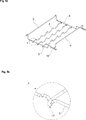
- Fig. 4a demonstrates a general perspective view of carrier rods and Fig. 4b demonstrates an enlarged view of a locking form at the end portions of the carrier rod according to the present invention.
- Fig. 5a demonstrates a general perspective view of the carrier rods attached to receiving rods and Fig. 5b demonstrates an enlarged view of the connection of a locking form with a usage slot of the receiving rod according to the present invention.
- Fig. 6 demonstrates a general perspective view of the carrier rods collected at a storage region of the receiving rod when the wire rack is not in use and Fig. 6b demonstrates an enlarged view of the storage region according to the present invention.
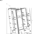
- Fig. 7 demonstrates a general perspective view of the carrier rods installed to the cooling unit when the wire rack is not in use.
- Fig. 8a demonstrates a general perspective view of a rail portion within the wire rack according to a second embodiment of the present invention and Fig. 8b demonstrates a separate view of the rail portion.
- Fig. 9 demonstrates a general perspective view of the assembled wire rack according to the second embodiment of the present invention.
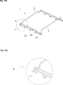
- Fig. 10a demonstrates a general perspective view of the carrier rods and Fig. 10b demonstrates an enlarged view of a locking form of the carrier rods according to the second embodiment of the present invention.
- Fig. 11 demonstrates another general perspective view of the assembled wire rack according to the second embodiment of the present invention.
- Fig. 12 demonstrates a general perspective view of the wire rack when the carrier rods are collected at the rear side of the wire rack according to the second embodiment of the present invention.
- Fig. 13a demonstrates a general perspective view of the wire rack according to the third embodiment of the present invention and Fig. 13b demonstrates a general perspective view of a roller portion according to the present invention.
- Fig. 14a demonstrates a general perspective view of the relatively positioned carrier rods within a roller channel and Fig. 14b demonstrates an enlarged view of the roller channel with roller portions according to the third embodiment of the present invention.
- Fig. 15a demonstrates a general perspective view of the main frame and Fig. 15b demonstrates an enlarged view of a storage region together with a roller slot according to the third embodiment of the present invention.
- Fig. 16a demonstrates a general perspective view of the carrier rods collected at the rear side of the roller channel and Fig. 16b demonstrates an enlarged view of the collected carrier rods according to the third embodiment of the present invention.
- the present invention provides a wire rack (1) for containers such as bottles in a cooling unit (2), the wire rack (1) comprising at least one carrier section (3), a main frame (7) with two oppositely situated receiving rods (6) at two sides of the main frame (7) and two stabilizing rods (9) positioned in parallel and extending between two ends of the carrier sections (3) along which bottles are placed.
- the carrier section (3) comprises carrier rods (4) having recesses (5) for receiving bottles.
- the recesses (5) can have a U-form, a semi-circular or a triangular shape so that bottles can be placed on the carrier rods (4) in a convenient manner.
- a carrier section (3) is formed by at least two carrier rods (4) to receive the bottle to ensure a stable storage. As the number of carrier rods (4) in a carrier section (3) increases, safer placement of the bottle on the rack is ensured as this also decreases the distance between successive carrier rods (4) and prevents the bottles from falling down between two consecutive rods.
- the carrier rods (4) are placed parallel to each other.
- the carrier section (3) is located horizontally in the cooling unit (2).
- the end portions of the carrier rods (4) are adapted to have locking forms (13) as curved shape extensions effectuating attachment of the carrier rods (4) with the receiving rods (6).
- the carrier rods (4) are connected by at least one supporting rod (8).
- the supporting rod (8) is attached to the carrier rods (4) in a perpendicular manner.
- the supporting rod (8) provides extra support for the carrier rods (4) and ensures a more stable and strong carrying section for the bottles.
- the carrier rods (4) of the wire rack (1) are movably installed to the main frame (7) by fitting the locking forms (13) thereof into usage slots (12) positioned on the receiving rods (6) at lateral sides of the main frame (7).
- the usage slots (12) are separated by receiving rod extensions (25) in the form of linear intermediate lines.
- each end of a carrier rod (4) is movably coupled to the receiving rods (6).
- Usage slots (12) of the receiving rods (6) releasably accommodate the carrier rod (4) and allow displacement of the carrier rods (4) into the depth of a refrigeration cabin of the cooling unit (2) back and forth.
- the carrier rods (4) may be collected at a storage region (11) positioned at the rear side of the receiving rods (6), therefore increasing the inner storage area in the case the carrier sections (3) are not needed.
- the receiving rods (6) are connected to stabilizing rods (9), thereby forming the main frame (7) of the wire rack (1).
- Two stabilizing rods (9) are provided to be connected at each end of the receiving rods (6).
- Stabilizing rods (9) provide support for the receiving rods (6) carrying the load on the carrier sections (3) when bottles are placed thereon.
- the main frame (7) of the present invention comprises an installment section (10) for the wire rack (1) to be secured to the cooling unit (2).
- the installment section (10) functions as a connection unit irrespective of whether the wire rack (1) is mounted directly onto the cooling unit separately or it is attached to a shelf portion of the cooling unit (2).
- the receiving rod (6) is formed as a rail section (14) in the form of a rectangular housing with a slideway (19).
- the rail section (14) comprises a flat surface (17) and a region with adjustable slots (16) within the slideway (19).
- the adjustable slots (16) ensure relative configuration of the carrier rods (4) with a shorter intermediate distance so as to carry smaller containers. In this way, closer arrangement of the carrier rods (4) is possible while a more compact configuration creates extra space at the rear side of the main frame (7) so that longer containers can be placed on the lower shelf whose storage area is increased.
- the slideway (19) of the rail section (14) comprises three fixed slots (15) providing releasable parking positions at the front and rear sides as well as in the middle part of the rail section (14).
- the carrier rods (4) can be therefore moved to the fixed slots (15) to be situated in a more stable manner.
- the fact that the adjustable slots (16) are provided at the front side enables a more convenient and practical use on the part of the user.
- the placement of the fixed slots (15) to the middle part and to the end portions of the rail section (14) ensures the balance of the main frame (7) in the case bigger and heavy containers are carried.
- the carrier rods (4) having an appropriately retaining locking form (13’) provides adequate support for the carrier rods (4) in the fixed slots (15) as well as in the adjustable slots (16).
- the rail section (14) is mountable to the main frame (7) in a practical manner by way of installing the same onto the receiving rod (6) through a longitudinal installment recess (18) thereof.
- the installment recess (18) of the rail section (14) is a U-shaped channel longitudinally receiving the receiving rod (6) as well as the two perpendicular bars (20) of the receiving rod (6) at both sides of the longitudinal portion thereof.
- the carrier rods (4) can be collected at a rear region when the carrier section (3) is not in use, thereby increasing the inner space of the cooling unit (2) and avoiding unnecessary occupation of the lower shelf upper space.
- the receiving rod (6) is formed as a channel having a plurality of roller channels (22) providing a track for a roller portion (21) coupled to the extremities of the carrier rod (4), allowing easy movement of the carrier rods (4) within the roller channels (22) and also preventing detachment of the carrier rods (4) during the displacement thereof.
- the roller channels (22) are formed by provision of an upper rod relative to the receiving rod (6).
- a generally cylindrical lateral surface in the form of a contact surface (23) of the roller portion (21) enables the rotational movement of the roller portion (21) within the roller channels (22).
- the roller portions (21) are firmly maintained when they enter into roller slots (24). Likewise, they can be collected at the storage region (11) positioned at the rear side of the rearmost roller channel (22) to increase the storage area of the cooling unit (2).
- the roller portions (21) provide ease of movement for the carrier rods (4).
- the present invention proposes a wire rack (1) to carry bottles, the wire rack (1) comprising at least one carrier section (3) extending in parallel with a main frame (7) having a pair of receiving rods (6) located opposite to each other and in connection with a pair of stabilizing rods (9) facing each other, the carrier section (3) being formed by at least two carrier rods (4) operably connected to the pair of receiving rods (6).
- the receiving rods (6) are associated with a plurality of parking positions (12, 15, 24) and a plurality of movement lines (16, 17, 22, 25) in the manner that the carrier rods (4) are movable along the plurality of movement lines (16, 17, 22, 25) and releasably secured at the plurality of parking positions (12, 15, 24).
- the receiving rods (6) comprise a plurality of usage slots (12) being shaped as a cavity between two receiving rod extensions (25) in the manner that a locking form (13) of the carrier rod (4) effectuates attachment of the carrier rod (4) with the receiving rod (6) in a guidably movable and releasable manner.
- the locking form (13) of the carrier rod (4) has a curved shape with the end portion being releasably engaged with the usage slots (12) and the receiving rod extensions (25).
- a rail section (14) is mountable to the receiving rod (6), the rail section (14) having a slideway (19) along which the carrier rods (4) are guidably movable.
- the rail section (14) comprises at least three fixed slots (15) into which the carrier rod (4) is fitted in a releasable manner.
- the at least three fixed slots (15) are disposed at least at two extremities and in the middle part of the rail section (14).
- the rail section (14) comprises an installment recess (18) in the form of a U-shaped channel longitudinally receiving the receiving rod (6) and the perpendicular bars (20) of the receiving rod (6) at both sides of the longitudinal portion thereof.
- the rail section (14) comprises a flat surface (17) and a region with adjustable slots (16) separated by a fixed slot (15) within the slideway (19), the adjustable slots (16) retaining the carrier rods (4) in an immovable position.
- the adjustable slots (16) therefore provide a greater flexibility compared to fixed slots (15) when configuring positions of the carrier rods (4). They yet provide an adequately firm positional support for the carrier rods (4) so as to maintain the same in an immovable carrying position.
- the adjustable slots (16) are in the form of consecutive semi-circular grooves having a diameter smaller than the cross-sectional diameter of the carrier rod (4).
- the semi-circular grooves of the adjustable slots (16) therefore partially retain the tubular body of the carrier rods (4) compared to the fixed slots (15) in which the tubular body of the carrier rods (4) are rested, therefore an increased number of temporary support positions are available along the adjustable slots (16).
- the region with adjustable slots (16) extends along the front half of the slideway (19). This provides a practical use on the part of the user as it is possible to arrange the front side of the wire rack (1) to meet the specific needs of the user such as for instance for accommodating smaller bottles in reach of the user.
- the receiving rods (6) comprise a plurality of roller channels (22) along which the carrier rods (4) are guidably movable, the roller channels (22) being separated by roller slots (24).
- a roller portion (21) coupled to the extremities of the carrier rod (4) enables movement of the carrier rods (4) within the roller channels (22).
- roller portions (21) are releasably secured within the roller slots (24).
- the carrier rods (4) are all together collectible at a storage region (11) positioned at the rear side of the receiving rods (6).
- a cooling unit (2) comprising the wire rack (1) is proposed.
- the present invention provides a configurable wire rack (1).
- the rail section (14) can be directly mounted to existing wire racks (1) to provide even greater flexibility. It provides adequately firm positional support for the carrier rods (4) so as to maintain the same in an immovable carrying position with an increased number of temporary support positions.
Landscapes
- Engineering & Computer Science (AREA)
- Chemical & Material Sciences (AREA)
- Combustion & Propulsion (AREA)
- Physics & Mathematics (AREA)
- Mechanical Engineering (AREA)
- Thermal Sciences (AREA)
- General Engineering & Computer Science (AREA)
- Devices That Are Associated With Refrigeration Equipment (AREA)
- Warehouses Or Storage Devices (AREA)
Abstract
The present invention pertains to a wire rack (1) adapted to carry containers such as wine bottles in a cooling unit (2) involving an adjustable, space-increasing wire rack (1) structure. The present invention more particularly pertains to a wire rack (1) to carry bottles, the wire rack (1) comprising at least one carrier section (3) extending in parallel with a main frame (7) having a pair of receiving rods (6) located opposite to each other and in connection with a pair of stabilizing rods (9) facing each other, the carrier section (3) being formed by at least two carrier rods (4) operatively connected to the pair of receiving rods (6).
Description
The present invention relates to a wire rack adapted to carry containers such as wine bottles in a cooling unit involving an adjustable, space-increasing wire rack structure.
A cooling unit or a refrigerator has a plurality of compartments and shelves for preserving food items and bottles. While a plurality of shelves may carry various size food containers, an adjustable bottle shelf may typically be employed to extend the inner capacity of the appliance to increase the inner space for maximum storage.
In refrigeration appliances, inner storing area efficiency is therefore one of the most important concerns for the consumer. There are different solutions in the state of the art provided for storing products having bigger dimensions such as wine bottles. To this end, various designs of shelf assemblies are proposed, having different techniques to increase the efficiency of the storage area usage.
The structure and size of bottles complicates the storing process. When stored vertically in a standing position, the length of the bottle usually exceeds the distance between the racks. This placement also has the disadvantage that the bottle may tumble over. If it is placed horizontally on its side, the circular structure of the bottle results in a mobile storage rather than a stable one, where the bottle is free to roll over.
To provide a stable storing in the cooling units for bottles, the storage area (e.g. the rack) is usually provided with recesses for the bottle to be placed on its side. Other systems propose the bottle to be placed in compartments that are located at the inner walls of the door.
A prior art publication in the technical field of the present invention may be referred to as CN2856880, disclosing a push-draw type wine bottle bracket and a refrigerator provided with the same. The refrigerator provided with a wine bottle bracket movably supported by a bearing plate comprises a refrigerating chamber and a freezing chamber. A bearing plate having a support frame thereon is provided inside the refrigerating chamber and a fixing groove unit is disposed on the bracket. The connection between the bracket and the plate is movable.
The present invention provides a wire rack for storing containers in a cooling unit, which is easy to manufacture, cost efficient and durable as defined by the characterizing features in Claim 1.
Primary object of the present invention is to provide a wire rack ensuring that the user can adjust carrier sections of the wire rack at different positions. The adjustment of the wire rack in different configurations provides minimization of the area the wire rack occupies within the cooling unit when not in use.
The present invention provides a wire rack for containers in a cooling unit, position of the carrier rods that constitute the carrier sections accommodating the bottles being configurable according to the needs of the user.
The user can collect the carrier rods to one place on the wire rack to increase the inner space of the cooling unit compartment. The present invention further enables the user to adjust the wire rack in the manner that the space occupied by the wire rack can be adjusted depending on the size of the bottles placed on the rack.
A rail section is provided to be readily mountable to existing wire racks so that it is possible to accommodate different size bottles/containers in a configurable manner. The rail section comprises fixed slots as well as adjustable slots, the adjustable slots being suitable for retaining the carrier rods at any desired position along the longitudinal direction of the receiving rods at two sides of the carrier rods.
Accompanying drawings are given solely for the purpose of exemplifying a wire rack for a cooling unit, whose advantages over prior art were outlined above and will be explained in brief hereinafter.
The drawings are not meant to delimit the scope of protection as identified in the claims nor should they be referred to alone in an effort to interpret the scope identified in the claims without recourse to the technical disclosure in the description of the present invention.
Fig. 1 demonstrates a general perspective view of a wire rack installed into a cooling unit according to the present invention.
Fig. 2 demonstrates a general perspective view of carrier sections in a main frame of the wire rack.
Fig. 3 demonstrates a general perspective view of the main frame of the wire rack according to the present invention.
Fig. 4a demonstrates a general perspective view of carrier rods and Fig. 4b demonstrates an enlarged view of a locking form at the end portions of the carrier rod according to the present invention.
Fig. 5a demonstrates a general perspective view of the carrier rods attached to receiving rods and Fig. 5b demonstrates an enlarged view of the connection of a locking form with a usage slot of the receiving rod according to the present invention.
Fig. 6 demonstrates a general perspective view of the carrier rods collected at a storage region of the receiving rod when the wire rack is not in use and Fig. 6b demonstrates an enlarged view of the storage region according to the present invention.
Fig. 7 demonstrates a general perspective view of the carrier rods installed to the cooling unit when the wire rack is not in use.
Fig. 8a demonstrates a general perspective view of a rail portion within the wire rack according to a second embodiment of the present invention and Fig. 8b demonstrates a separate view of the rail portion.
Fig. 9 demonstrates a general perspective view of the assembled wire rack according to the second embodiment of the present invention.
Fig. 10a demonstrates a general perspective view of the carrier rods and Fig. 10b demonstrates an enlarged view of a locking form of the carrier rods according to the second embodiment of the present invention.
Fig. 11 demonstrates another general perspective view of the assembled wire rack according to the second embodiment of the present invention.
Fig. 12 demonstrates a general perspective view of the wire rack when the carrier rods are collected at the rear side of the wire rack according to the second embodiment of the present invention.
Fig. 13a demonstrates a general perspective view of the wire rack according to the third embodiment of the present invention and Fig. 13b demonstrates a general perspective view of a roller portion according to the present invention.
Fig. 14a demonstrates a general perspective view of the relatively positioned carrier rods within a roller channel and Fig. 14b demonstrates an enlarged view of the roller channel with roller portions according to the third embodiment of the present invention.
Fig. 15a demonstrates a general perspective view of the main frame and Fig. 15b demonstrates an enlarged view of a storage region together with a roller slot according to the third embodiment of the present invention.
Fig. 16a demonstrates a general perspective view of the carrier rods collected at the rear side of the roller channel and Fig. 16b demonstrates an enlarged view of the collected carrier rods according to the third embodiment of the present invention.
The following numerals are assigned to different parts demonstrated in the drawings:
- Wire rack
- Cooling unit
- Carrier section
- Carrier rod
- Recess
- Receiving rod
- Main frame
- Supporting rod
- Stabilizing rod
- Installment section
- Storage region
- Usage slot
- Locking form
- Rail section
- Fixed slot
- Adjustable slots
- Flat surface
- Installment recess
- Slideway
- Perpendicular bar
- Roller portion
- Roller channel
- Contact surface
- Roller slot
- Receiving rod extension
The present invention provides a wire rack (1) for containers such as bottles in a cooling unit (2), the wire rack (1) comprising at least one carrier section (3), a main frame (7) with two oppositely situated receiving rods (6) at two sides of the main frame (7) and two stabilizing rods (9) positioned in parallel and extending between two ends of the carrier sections (3) along which bottles are placed.
The carrier section (3) comprises carrier rods (4) having recesses (5) for receiving bottles. The recesses (5) can have a U-form, a semi-circular or a triangular shape so that bottles can be placed on the carrier rods (4) in a convenient manner. A carrier section (3) is formed by at least two carrier rods (4) to receive the bottle to ensure a stable storage. As the number of carrier rods (4) in a carrier section (3) increases, safer placement of the bottle on the rack is ensured as this also decreases the distance between successive carrier rods (4) and prevents the bottles from falling down between two consecutive rods. The carrier rods (4) are placed parallel to each other. The carrier section (3) is located horizontally in the cooling unit (2). The end portions of the carrier rods (4) are adapted to have locking forms (13) as curved shape extensions effectuating attachment of the carrier rods (4) with the receiving rods (6).
The carrier rods (4) are connected by at least one supporting rod (8). The supporting rod (8) is attached to the carrier rods (4) in a perpendicular manner. The supporting rod (8) provides extra support for the carrier rods (4) and ensures a more stable and strong carrying section for the bottles.
According to a first embodiment of the present invention, the carrier rods (4) of the wire rack (1) are movably installed to the main frame (7) by fitting the locking forms (13) thereof into usage slots (12) positioned on the receiving rods (6) at lateral sides of the main frame (7). The usage slots (12) are separated by receiving rod extensions (25) in the form of linear intermediate lines. In other words, each end of a carrier rod (4) is movably coupled to the receiving rods (6). Usage slots (12) of the receiving rods (6) releasably accommodate the carrier rod (4) and allow displacement of the carrier rods (4) into the depth of a refrigeration cabin of the cooling unit (2) back and forth. Further, the carrier rods (4) may be collected at a storage region (11) positioned at the rear side of the receiving rods (6), therefore increasing the inner storage area in the case the carrier sections (3) are not needed.
The receiving rods (6) are connected to stabilizing rods (9), thereby forming the main frame (7) of the wire rack (1). Two stabilizing rods (9) are provided to be connected at each end of the receiving rods (6). Stabilizing rods (9) provide support for the receiving rods (6) carrying the load on the carrier sections (3) when bottles are placed thereon.
The main frame (7) of the present invention comprises an installment section (10) for the wire rack (1) to be secured to the cooling unit (2). The installment section (10) functions as a connection unit irrespective of whether the wire rack (1) is mounted directly onto the cooling unit separately or it is attached to a shelf portion of the cooling unit (2).
In accordance with a second embodiment of the present invention, the receiving rod (6) is formed as a rail section (14) in the form of a rectangular housing with a slideway (19). The rail section (14) comprises a flat surface (17) and a region with adjustable slots (16) within the slideway (19). The adjustable slots (16) ensure relative configuration of the carrier rods (4) with a shorter intermediate distance so as to carry smaller containers. In this way, closer arrangement of the carrier rods (4) is possible while a more compact configuration creates extra space at the rear side of the main frame (7) so that longer containers can be placed on the lower shelf whose storage area is increased.
The slideway (19) of the rail section (14) comprises three fixed slots (15) providing releasable parking positions at the front and rear sides as well as in the middle part of the rail section (14). The carrier rods (4) can be therefore moved to the fixed slots (15) to be situated in a more stable manner. The fact that the adjustable slots (16) are provided at the front side enables a more convenient and practical use on the part of the user. On the other hand, the placement of the fixed slots (15) to the middle part and to the end portions of the rail section (14) ensures the balance of the main frame (7) in the case bigger and heavy containers are carried. The carrier rods (4) having an appropriately retaining locking form (13’) provides adequate support for the carrier rods (4) in the fixed slots (15) as well as in the adjustable slots (16).
The rail section (14) is mountable to the main frame (7) in a practical manner by way of installing the same onto the receiving rod (6) through a longitudinal installment recess (18) thereof. The installment recess (18) of the rail section (14) is a U-shaped channel longitudinally receiving the receiving rod (6) as well as the two perpendicular bars (20) of the receiving rod (6) at both sides of the longitudinal portion thereof. Likewise, the carrier rods (4) can be collected at a rear region when the carrier section (3) is not in use, thereby increasing the inner space of the cooling unit (2) and avoiding unnecessary occupation of the lower shelf upper space.
In accordance with a third embodiment of the present invention, the receiving rod (6) is formed as a channel having a plurality of roller channels (22) providing a track for a roller portion (21) coupled to the extremities of the carrier rod (4), allowing easy movement of the carrier rods (4) within the roller channels (22) and also preventing detachment of the carrier rods (4) during the displacement thereof. The roller channels (22) are formed by provision of an upper rod relative to the receiving rod (6).
A generally cylindrical lateral surface in the form of a contact surface (23) of the roller portion (21) enables the rotational movement of the roller portion (21) within the roller channels (22). The roller portions (21) are firmly maintained when they enter into roller slots (24). Likewise, they can be collected at the storage region (11) positioned at the rear side of the rearmost roller channel (22) to increase the storage area of the cooling unit (2). The roller portions (21) provide ease of movement for the carrier rods (4).
In summary, the present invention proposes a wire rack (1) to carry bottles, the wire rack (1) comprising at least one carrier section (3) extending in parallel with a main frame (7) having a pair of receiving rods (6) located opposite to each other and in connection with a pair of stabilizing rods (9) facing each other, the carrier section (3) being formed by at least two carrier rods (4) operably connected to the pair of receiving rods (6).
In one embodiment of the present invention, the receiving rods (6) are associated with a plurality of parking positions (12, 15, 24) and a plurality of movement lines (16, 17, 22, 25) in the manner that the carrier rods (4) are movable along the plurality of movement lines (16, 17, 22, 25) and releasably secured at the plurality of parking positions (12, 15, 24).
In a further embodiment of the present invention, the receiving rods (6) comprise a plurality of usage slots (12) being shaped as a cavity between two receiving rod extensions (25) in the manner that a locking form (13) of the carrier rod (4) effectuates attachment of the carrier rod (4) with the receiving rod (6) in a guidably movable and releasable manner.
In a further embodiment of the present invention, the locking form (13) of the carrier rod (4) has a curved shape with the end portion being releasably engaged with the usage slots (12) and the receiving rod extensions (25).
In a further embodiment of the present invention, a rail section (14) is mountable to the receiving rod (6), the rail section (14) having a slideway (19) along which the carrier rods (4) are guidably movable.
In a further embodiment of the present invention, the rail section (14) comprises at least three fixed slots (15) into which the carrier rod (4) is fitted in a releasable manner.
In a further embodiment of the present invention, the at least three fixed slots (15) are disposed at least at two extremities and in the middle part of the rail section (14).
In a further embodiment of the present invention, the rail section (14) comprises an installment recess (18) in the form of a U-shaped channel longitudinally receiving the receiving rod (6) and the perpendicular bars (20) of the receiving rod (6) at both sides of the longitudinal portion thereof. The structure of the rail section (14) as a separate unit practically mountable to the existing receiving rods (6) without any further modification due to the structure of the installment recess (18), advantageously provides the wire rack with more improved features according to the second embodiment of the present invention.
In a further embodiment of the present invention, the rail section (14) comprises a flat surface (17) and a region with adjustable slots (16) separated by a fixed slot (15) within the slideway (19), the adjustable slots (16) retaining the carrier rods (4) in an immovable position. The adjustable slots (16) therefore provide a greater flexibility compared to fixed slots (15) when configuring positions of the carrier rods (4). They yet provide an adequately firm positional support for the carrier rods (4) so as to maintain the same in an immovable carrying position.
In a further embodiment of the present invention, the adjustable slots (16) are in the form of consecutive semi-circular grooves having a diameter smaller than the cross-sectional diameter of the carrier rod (4). The semi-circular grooves of the adjustable slots (16) therefore partially retain the tubular body of the carrier rods (4) compared to the fixed slots (15) in which the tubular body of the carrier rods (4) are rested, therefore an increased number of temporary support positions are available along the adjustable slots (16).
In a further embodiment of the present invention, the region with adjustable slots (16) extends along the front half of the slideway (19). This provides a practical use on the part of the user as it is possible to arrange the front side of the wire rack (1) to meet the specific needs of the user such as for instance for accommodating smaller bottles in reach of the user.
In a further embodiment of the present invention, the receiving rods (6) comprise a plurality of roller channels (22) along which the carrier rods (4) are guidably movable, the roller channels (22) being separated by roller slots (24).
In a further embodiment of the present invention, a roller portion (21) coupled to the extremities of the carrier rod (4) enables movement of the carrier rods (4) within the roller channels (22).
In a further embodiment of the present invention, the roller portions (21) are releasably secured within the roller slots (24).
In a further embodiment of the present invention, the carrier rods (4) are all together collectible at a storage region (11) positioned at the rear side of the receiving rods (6).
In a further embodiment of the present invention, a cooling unit (2) comprising the wire rack (1) is proposed.
Therefore, the present invention provides a configurable wire rack (1). The rail section (14) can be directly mounted to existing wire racks (1) to provide even greater flexibility. It provides adequately firm positional support for the carrier rods (4) so as to maintain the same in an immovable carrying position with an increased number of temporary support positions.
Claims (15)
- A wire rack (1) to carry containers, the wire rack (1) comprising at least one carrier section (3) within a main frame (7) having a pair of receiving rods (6) located opposite to each other and in connection with a pair of stabilizing rods (9) facing each other, the carrier section (3) being formed by at least two carrier rods (4) operably connected to the pair of receiving rods (6), characterized in thatthe receiving rods (6) are associated with a plurality of parking positions (12, 15, and 24) and a plurality of movement lines (16, 17, 22 and 25) in the manner that the carrier rods (4) are movable along the plurality of movement lines (16, 17, 22 and 25) and releasably secured at the plurality of parking positions (12, 15 and 24).
- A wire rack (1) as in Claim 1, characterized in that the receiving rods (6) comprise a plurality of usage slots (12) being shaped as a cavity between two receiving rod extensions (25) in the manner that a locking form (13) of the carrier rod (4) effectuates attachment of the carrier rod (4) with the receiving rod (6) in a guidably movable and releasable manner.
- A wire rack (1) as in Claim 2, characterized in that the locking form (13) of the carrier rod (4) has a curved shape with the end portion being releasably engaged with the usage slots (12) and the receiving rod extensions (25).
- A wire rack (1) as in Claim 1, characterized in that a rail section (14) is mountable to the receiving rod (6), the rail section (14) having a slideway (19) along which the carrier rods (4) are guidably movable.
- A wire rack (1) as in Claim 4, characterized in that the rail section (14) comprises at least three fixed slots (15) into which the carrier rod (4) is fitted in a releasable manner.
- A wire rack (1) as in Claim 5, characterized in that the at least three fixed slots (15) are disposed at least at two extremities and in the middle part of the rail section (14).
- A wire rack (1) as in Claim 4, 5 or 6, characterized in that the rail section (14) comprises an installment recess (18) in the form of a U-shaped channel longitudinally receiving the receiving rod (6) and the perpendicular bars (20) of the receiving rod (6) at both sides of the longitudinal portion thereof.
- A wire rack (1) as in Claim 5, 6 or 7, characterized in that the rail section (14) comprises a flat surface (17) and a region with adjustable slots (16) separated by a fixed slot (15) within the slideway (19), the adjustable slots (16) retaining the carrier rods (4) in an immovable position.
- A wire rack (1) as in Claim 8, characterized in that the adjustable slots (16) are in the form of consecutive semi-circular grooves having a diameter smaller than the cross-sectional diameter of the carrier rod (4).
- A wire rack (1) as in Claim 8 or 9, characterized in that the region with adjustable slots (16) extends along the front half of the slideway (19).
- A wire rack (1) as in Claim 1, characterized in that the receiving rods (6) comprise a plurality of roller channels (22) along which the carrier rods (4) are guidably movable, the roller channels (22) being separated by roller slots (24).
- A wire rack (1) as in Claim 11, characterized in that a roller portion (21) coupled to the extremities of the carrier rod (4) enables movement of the carrier rods (4) within the roller channels (22).
- A wire rack (1) as in Claim 12, characterized in that the roller portions (21) are releasably secured within the roller slots (24).
- A wire rack (1) as in Claim 1, 4 or 11, characterized in that the carrier rods (4) are all together collectible at a storage region (11) positioned at the rear side of the receiving rods (6).
- A cooling unit (2) comprising the wire rack (1) as set forth in any preceding Claims.
Priority Applications (2)
| Application Number | Priority Date | Filing Date | Title |
|---|---|---|---|
| PCT/EP2015/051886 WO2016119870A1 (en) | 2015-01-30 | 2015-01-30 | Cooling unit with a wire rack assembly adapted to carry containers |
| TR2016/01182A TR201601182A2 (en) | 2015-01-30 | 2016-01-28 | REFRIGERATOR WITH A WIRE SHELF SYSTEM INCLUDING CONTAINERS |
Applications Claiming Priority (1)
| Application Number | Priority Date | Filing Date | Title |
|---|---|---|---|
| PCT/EP2015/051886 WO2016119870A1 (en) | 2015-01-30 | 2015-01-30 | Cooling unit with a wire rack assembly adapted to carry containers |
Publications (1)
| Publication Number | Publication Date |
|---|---|
| WO2016119870A1 true WO2016119870A1 (en) | 2016-08-04 |
Family
ID=52434821
Family Applications (1)
| Application Number | Title | Priority Date | Filing Date |
|---|---|---|---|
| PCT/EP2015/051886 Ceased WO2016119870A1 (en) | 2015-01-30 | 2015-01-30 | Cooling unit with a wire rack assembly adapted to carry containers |
Country Status (2)
| Country | Link |
|---|---|
| TR (1) | TR201601182A2 (en) |
| WO (1) | WO2016119870A1 (en) |
Cited By (1)
| Publication number | Priority date | Publication date | Assignee | Title |
|---|---|---|---|---|
| CN107212633A (en) * | 2017-06-19 | 2017-09-29 | 青岛海尔特种电冰柜有限公司 | A kind of adjustable wine frame and application method |
Citations (5)
| Publication number | Priority date | Publication date | Assignee | Title |
|---|---|---|---|---|
| CH390965A (en) * | 1963-12-02 | 1965-04-30 | Merz Meyer Ag | Drawer, in particular refrigerated drawer in refrigerated furniture |
| CN2562149Y (en) * | 2002-06-10 | 2003-07-23 | 广东科龙电器股份有限公司 | Foldable wine bottle shelf |
| CN2856880Y (en) | 2006-01-10 | 2007-01-10 | 海信集团有限公司 | Sliding wine bottle rack and refrigerator with the same |
| WO2007054916A2 (en) * | 2005-11-14 | 2007-05-18 | Arcelik Anonim Sirketi | A cooling device |
| CN102494509B (en) * | 2011-12-13 | 2014-01-15 | 合肥美的电冰箱有限公司 | Refrigerator |
-
2015
- 2015-01-30 WO PCT/EP2015/051886 patent/WO2016119870A1/en not_active Ceased
-
2016
- 2016-01-28 TR TR2016/01182A patent/TR201601182A2/en unknown
Patent Citations (5)
| Publication number | Priority date | Publication date | Assignee | Title |
|---|---|---|---|---|
| CH390965A (en) * | 1963-12-02 | 1965-04-30 | Merz Meyer Ag | Drawer, in particular refrigerated drawer in refrigerated furniture |
| CN2562149Y (en) * | 2002-06-10 | 2003-07-23 | 广东科龙电器股份有限公司 | Foldable wine bottle shelf |
| WO2007054916A2 (en) * | 2005-11-14 | 2007-05-18 | Arcelik Anonim Sirketi | A cooling device |
| CN2856880Y (en) | 2006-01-10 | 2007-01-10 | 海信集团有限公司 | Sliding wine bottle rack and refrigerator with the same |
| CN102494509B (en) * | 2011-12-13 | 2014-01-15 | 合肥美的电冰箱有限公司 | Refrigerator |
Cited By (1)
| Publication number | Priority date | Publication date | Assignee | Title |
|---|---|---|---|---|
| CN107212633A (en) * | 2017-06-19 | 2017-09-29 | 青岛海尔特种电冰柜有限公司 | A kind of adjustable wine frame and application method |
Also Published As
| Publication number | Publication date |
|---|---|
| TR201601182A2 (en) | 2016-09-21 |
Similar Documents
| Publication | Publication Date | Title |
|---|---|---|
| EP2419691B1 (en) | Sliding shelf for refrigerators and freezers | |
| US8720702B2 (en) | Merchandise pusher tray with adjustable side barriers | |
| US2287611A (en) | Shelf | |
| EP2702337B1 (en) | Crisper drawers with rollers and ramp | |
| EP2175218B1 (en) | Refrigerator | |
| EP2159523B1 (en) | Refrigeration equipment and console system for use therein | |
| US20140117830A1 (en) | Refrigerator | |
| WO2017029625A1 (en) | Appliance with geared drawer assembly | |
| CN103210270B (en) | Refrigerating appliance with a storage surface for storing refrigerated items | |
| US8002369B2 (en) | Slide system for drawers or shelves in an appliance | |
| KR20160141787A (en) | Sliding/pivoting mechanism of a shelf of a piece of furniture or of a domestic appliance, domestic appliance, and piece of furniture | |
| CN101990623B (en) | Refrigeration appliances | |
| US8356865B2 (en) | Refrigerating device with pull-out carrier for refrigerated goods | |
| WO2016119870A1 (en) | Cooling unit with a wire rack assembly adapted to carry containers | |
| CN203336894U (en) | Shelf assembly used for refrigerator and refrigerator | |
| EP3149413B1 (en) | Wire rack for a cooling unit | |
| KR20140013378A (en) | A wheels mountkng structure of guide rail for drawer shaper refrigerator | |
| WO2012062882A2 (en) | A cooling device | |
| WO2015096912A1 (en) | A cooling device comprising a bottle holder | |
| EP3250866B1 (en) | Refrigeration appliance with a shelf assembly | |
| KR200180225Y1 (en) | Wine bottle holder for refrigerator | |
| KR100646342B1 (en) | Showcase shelves | |
| US2058864A (en) | Refrigerating apparatus | |
| CN220135836U (en) | Wine rack and refrigerator with same | |
| KR101513030B1 (en) | Refrigerator |
Legal Events
| Date | Code | Title | Description |
|---|---|---|---|
| 121 | Ep: the epo has been informed by wipo that ep was designated in this application |
Ref document number: 15701802 Country of ref document: EP Kind code of ref document: A1 |
|
| NENP | Non-entry into the national phase |
Ref country code: DE |
|
| 122 | Ep: pct application non-entry in european phase |
Ref document number: 15701802 Country of ref document: EP Kind code of ref document: A1 |