WO2016119830A1 - Pyrolytic oven with improved operability and safety - Google Patents
Pyrolytic oven with improved operability and safety Download PDFInfo
- Publication number
- WO2016119830A1 WO2016119830A1 PCT/EP2015/051653 EP2015051653W WO2016119830A1 WO 2016119830 A1 WO2016119830 A1 WO 2016119830A1 EP 2015051653 W EP2015051653 W EP 2015051653W WO 2016119830 A1 WO2016119830 A1 WO 2016119830A1
- Authority
- WO
- WIPO (PCT)
- Prior art keywords
- chamber
- bulb
- oven
- door
- disposed
- Prior art date
- Legal status (The legal status is an assumption and is not a legal conclusion. Google has not performed a legal analysis and makes no representation as to the accuracy of the status listed.)
- Ceased
Links
Images

Classifications
-
- F—MECHANICAL ENGINEERING; LIGHTING; HEATING; WEAPONS; BLASTING
- F24—HEATING; RANGES; VENTILATING
- F24C—DOMESTIC STOVES OR RANGES ; DETAILS OF DOMESTIC STOVES OR RANGES, OF GENERAL APPLICATION
- F24C14/00—Stoves or ranges having self-cleaning provisions, e.g. continuous catalytic cleaning or electrostatic cleaning
- F24C14/02—Stoves or ranges having self-cleaning provisions, e.g. continuous catalytic cleaning or electrostatic cleaning pyrolytic type
Definitions
- the present invention relates to a pyrolytic oven, in particular a pyrolytic oven for domestic use.
- Pyrolytic ovens are commonly known. During the cooking/baking process the inner lining of the chamber is generally spoiled with food residues. The cleaning of the hardened food residues is usually very laborious. In a pyrolytic oven, the food residues can be burned off by heating the chamber up to temperatures above 480 °C. In general, in the pyrolytic oven the inner lining of the chamber has a smooth surface. Thereby, the food residues easily peel off during the pyrolysis. Thus, after the chamber has cooled down, the user can easily collect the ashes from the bottom of the chamber. The pyrolytic function greatly facilitates cleaning of the cooking/baking chamber.
- a drawback of the pyrolytic oven is that during the pyrolysis, the high temperature prevailing inside the chamber poses a severe health risk to the user.
- the hot air inside the chamber as well as the hot component parts of the chamber can cause skin burns and scalding when the user opens the door during the pyrolysis.
- An objective of the present invention is to provide a pyrolytic oven which overcomes the aforementioned drawbacks of the prior art in a cost-effective way and which enables a reliable protection of the user from the hazards of the excessive heat.
- the pyrolytic oven of the present invention comprises: a lock unit for locking/unlocking the door; a bulb thermostat for sensing and regulating the temperature inside the chamber during the pyrolysis and also during the cooking, wherein the bulb is immovably disposed into the chamber and a heat protective shield which is disposed into the chamber and arranged to screen the bulb from the convective and radiative heat flux generated by the heating unit.
- the bulb thermostat is configured to cause the lock unit to lock or unlock the door when the temperature inside the chamber respectively exceeds or drops below a threshold temperature characteristic of the pyrolysis.
- the chamber is heated up to temperatures above 480 degrees.
- the door can be reliably locked exclusively during the pyrolysis when the temperature reaches about 320 degrees which is characteristic of the pyrolysis.
- the bulb thermostat is used for sensing and regulating the temperature inside the chamber not only during the pyrolysis but also during the cooking.
- the need for utilizing an additional thermostat has been obviated and thus, the production costs have been comparatively reduced.
- the door can be prevented from being locked during the cooking due to the excessive convective and radiative heating of the bulb.
- the pyrolytic oven can be reliably and safely operated both during the pyrolysis and the cooking. Thereby, a consumer satisfaction can be increased.
- the heat protective shield has ventilation openings.
- the response of the bulb to the temperature prevailing inside the chamber during the cooking/baking has been improved.
- the thermostat can more reliably regulate the cooking/baking process.
- the ventilation openings may have different size and shapes and may also be arranged in various different ways depending on the size and shape, the alignment and the position of the bulb.
- the heat protective shield is formed from a sheet metal.
- the heat protective shield has an elongated shape which matches the bulb. The heat protective shield is mounted into the chamber by screwing, welding or any other method known to the person skilled in the art.
- Figure 1 – is a schematic partial front view of a pyrolytic oven which has a heat protective shield according to an embodiment of the present invention
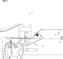
- Figure 2 – is a schematic partial vertical sectional view of the pyrolytic oven which has the heat protective shield according to an embodiment of the present invention
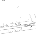
- Figure 3 – is a schematic partial inner view of the pyrolytic oven which has the heat protective shield according to an embodiment of the present invention.
- the pyrolytic oven (1) comprises a chamber (2) for cooking food, a door (not shown) for accessing the chamber (2) and a heating unit (3) for heating the interior of the chamber (2).
- the pyrolytic oven (1) of the present invention further comprises: a lock unit (not shown) for locking/unlocking the door; a bulb thermostat (4) for sensing and regulating the temperature inside the chamber (2) during the pyrolysis and also during the cooking, wherein the bulb (5) is immovably disposed into the chamber (2) and a heat protective shield (6) which is disposed into the chamber (2) and arranged to screen the bulb (5) from the convective and radiative heat flux generated by the heating unit (3).
- the bulb thermostat (4) is configured to cause the lock unit to lock or unlock the door when the temperature inside the chamber (2) respectively exceeds or drops below a threshold temperature characteristic of the pyrolysis (Fig. 1 to 3).
- the heat protective shield (6) comprises one or more than one ventilation opening (7).
- the heating unit (3) comprises: an upper electrical heater (8) which is disposed immediately below the ceiling (9) of the chamber (2) and a fan (10) and a rear electrical heater (11) which are disposed behind a partially perforated and heat protective rear wall (12) of the chamber (2).
- the bulb (5) is disposed in close proximity to the upper electrical heater (8).
- the heat protective shield (6) is arranged between the bulb (5) and the upper electrical heater (8) and also between the bulb (5) and the perforations (13) of the rear wall (12).
- the bulb thermostat (4) and the heat protective shield (6) are fixed to the ceiling (9) of the chamber (2).
Landscapes
- Chemical & Material Sciences (AREA)
- Engineering & Computer Science (AREA)
- Chemical Kinetics & Catalysis (AREA)
- Combustion & Propulsion (AREA)
- Mechanical Engineering (AREA)
- General Engineering & Computer Science (AREA)
- Electric Stoves And Ranges (AREA)
Abstract
The present invention relates to a pyrolytic oven (1) which comprises a chamber (2), a door and a heating unit (3). The pyrolytic oven (1) of the present invention further comprises a lock unit for locking/unlocking the door, a bulb thermostat (4) for sensing and regulating the temperature inside the chamber (2), wherein the bulb (5) is disposed into the chamber (2) and a heat protective shield (6) which is disposed into the chamber (2) and arranged to screen the bulb (5) from the convective and radiative heat flux of the heating unit (3). The bulb thermostat (4) causes the lock unit to lock or unlock the door when the temperature inside the chamber (2) respectively exceeds or drops below a threshold temperature characteristic of the pyrolysis.
Description
The present invention relates to a pyrolytic oven, in particular a pyrolytic oven for domestic use.
Pyrolytic ovens are commonly known. During the cooking/baking process the inner lining of the chamber is generally spoiled with food residues. The cleaning of the hardened food residues is usually very laborious. In a pyrolytic oven, the food residues can be burned off by heating the chamber up to temperatures above 480 °C. In general, in the pyrolytic oven the inner lining of the chamber has a smooth surface. Thereby, the food residues easily peel off during the pyrolysis. Thus, after the chamber has cooled down, the user can easily collect the ashes from the bottom of the chamber. The pyrolytic function greatly facilitates cleaning of the cooking/baking chamber. A drawback of the pyrolytic oven is that during the pyrolysis, the high temperature prevailing inside the chamber poses a severe health risk to the user. The hot air inside the chamber as well as the hot component parts of the chamber can cause skin burns and scalding when the user opens the door during the pyrolysis.
An objective of the present invention is to provide a pyrolytic oven which overcomes the aforementioned drawbacks of the prior art in a cost-effective way and which enables a reliable protection of the user from the hazards of the excessive heat.
This objective has been achieved by the pyrolytic oven as defined in claim 1. Further achievements have been attained by the subject-matters respectively defined in the dependent claims.
The pyrolytic oven of the present invention comprises: a lock unit for locking/unlocking the door; a bulb thermostat for sensing and regulating the temperature inside the chamber during the pyrolysis and also during the cooking, wherein the bulb is immovably disposed into the chamber and a heat protective shield which is disposed into the chamber and arranged to screen the bulb from the convective and radiative heat flux generated by the heating unit. The bulb thermostat is configured to cause the lock unit to lock or unlock the door when the temperature inside the chamber respectively exceeds or drops below a threshold temperature characteristic of the pyrolysis.
According to the present invention, during the pyrolysis the chamber is heated up to temperatures above 480 degrees. With the present invention, the door can be reliably locked exclusively during the pyrolysis when the temperature reaches about 320 degrees which is characteristic of the pyrolysis. In the pyrolytic oven of the present invention, the bulb thermostat is used for sensing and regulating the temperature inside the chamber not only during the pyrolysis but also during the cooking. With the present invention, the need for utilizing an additional thermostat has been obviated and thus, the production costs have been comparatively reduced. With the present invention, particularly by virtue of the heat protective shield, the door can be prevented from being locked during the cooking due to the excessive convective and radiative heating of the bulb. With the present invention, the pyrolytic oven can be reliably and safely operated both during the pyrolysis and the cooking. Thereby, a consumer satisfaction can be increased.
In an embodiment, the heat protective shield has ventilation openings. Thereby, the response of the bulb to the temperature prevailing inside the chamber during the cooking/baking has been improved. Thereby, the thermostat can more reliably regulate the cooking/baking process. In different versions of this embodiment, the ventilation openings may have different size and shapes and may also be arranged in various different ways depending on the size and shape, the alignment and the position of the bulb.
In another embodiment, the heat protective shield is formed from a sheet metal. In a version of this embodiment, the heat protective shield has an elongated shape which matches the bulb. The heat protective shield is mounted into the chamber by screwing, welding or any other method known to the person skilled in the art.
Additional advantages of the pyrolytic oven of the present invention will become apparent with the detailed description of the embodiments with reference to the accompanying drawings in which:
Figure 1 – is a schematic partial front view of a pyrolytic oven which has a heat protective shield according to an embodiment of the present invention;
Figure 2 – is a schematic partial vertical sectional view of the pyrolytic oven which has the heat protective shield according to an embodiment of the present invention;
Figure 3 – is a schematic partial inner view of the pyrolytic oven which has the heat protective shield according to an embodiment of the present invention.
The reference signs appearing on the drawings relate to the following technical features.
- Oven
- Chamber
- Heating unit
- Bulb thermostat
- Bulb
- Shield
- Opening
- Heater
- Ceiling
- Fan
- Heater
- Rear wall
- Perforation
The pyrolytic oven (1) comprises a chamber (2) for cooking food, a door (not shown) for accessing the chamber (2) and a heating unit (3) for heating the interior of the chamber (2).
The pyrolytic oven (1) of the present invention further comprises: a lock unit (not shown) for locking/unlocking the door; a bulb thermostat (4) for sensing and regulating the temperature inside the chamber (2) during the pyrolysis and also during the cooking, wherein the bulb (5) is immovably disposed into the chamber (2) and a heat protective shield (6) which is disposed into the chamber (2) and arranged to screen the bulb (5) from the convective and radiative heat flux generated by the heating unit (3). The bulb thermostat (4) is configured to cause the lock unit to lock or unlock the door when the temperature inside the chamber (2) respectively exceeds or drops below a threshold temperature characteristic of the pyrolysis (Fig. 1 to 3).
In an embodiment, the heat protective shield (6) comprises one or more than one ventilation opening (7).
In another embodiment, the heating unit (3) comprises: an upper electrical heater (8) which is disposed immediately below the ceiling (9) of the chamber (2) and a fan (10) and a rear electrical heater (11) which are disposed behind a partially perforated and heat protective rear wall (12) of the chamber (2). In this embodiment, the bulb (5) is disposed in close proximity to the upper electrical heater (8). In addition, the heat protective shield (6) is arranged between the bulb (5) and the upper electrical heater (8) and also between the bulb (5) and the perforations (13) of the rear wall (12).
In another embodiment, the bulb thermostat (4) and the heat protective shield (6) are fixed to the ceiling (9) of the chamber (2).
Claims (4)
- A pyrolytic oven (1) comprising a chamber (2) for cooking food, a door for accessing the chamber (2) and a heating unit (3) for heating the interior of the chamber (2), characterized in that a lock unit for locking/unlocking the door, a bulb thermostat (4) for sensing and regulating the temperature inside the chamber (2) during the pyrolysis and also during the cooking, wherein the bulb (5) is immovably disposed into the chamber (2) and a heat protective shield (6) which is disposed into the chamber (2) and arranged to screen the bulb (5) from the convective and radiative heat flux which is generated by the heating unit (3), wherein the bulb thermostat (4) is configured to cause the lock unit to lock or unlock the door when the temperature inside the chamber (2) respectively exceeds or drops below a threshold temperature characteristic of the pyrolysis.
- The oven (1) according to claim 1, characterized in that the heat protective shield (6) comprising one or more than one ventilation opening (7).
- The oven (1) according to claim 1 or 2, characterized in that the heating unit (3) comprises: an upper electrical heater (8) which is disposed immediately below the ceiling (9) of the chamber (2) and a fan (10) and a rear electrical heater (11) which are disposed behind a partially perforated and heat protective rear wall (12) of the chamber (2), wherein the bulb (5) is disposed in close proximity to the upper electrical heater (8) and wherein the heat protective shield (6) is arranged between the bulb (5) and the upper electrical heater (8) and also between the bulb (5) and the perforations (13) of the rear wall (12).
- The oven (1) according to claim 3, characterized in that the bulb thermostat (4) and the heat protective shield (6) are fixed to the ceiling (9) of the chamber (2).
Priority Applications (1)
| Application Number | Priority Date | Filing Date | Title |
|---|---|---|---|
| PCT/EP2015/051653 WO2016119830A1 (en) | 2015-01-28 | 2015-01-28 | Pyrolytic oven with improved operability and safety |
Applications Claiming Priority (1)
| Application Number | Priority Date | Filing Date | Title |
|---|---|---|---|
| PCT/EP2015/051653 WO2016119830A1 (en) | 2015-01-28 | 2015-01-28 | Pyrolytic oven with improved operability and safety |
Publications (1)
| Publication Number | Publication Date |
|---|---|
| WO2016119830A1 true WO2016119830A1 (en) | 2016-08-04 |
Family
ID=52396710
Family Applications (1)
| Application Number | Title | Priority Date | Filing Date |
|---|---|---|---|
| PCT/EP2015/051653 Ceased WO2016119830A1 (en) | 2015-01-28 | 2015-01-28 | Pyrolytic oven with improved operability and safety |
Country Status (1)
| Country | Link |
|---|---|
| WO (1) | WO2016119830A1 (en) |
Citations (3)
| Publication number | Priority date | Publication date | Assignee | Title |
|---|---|---|---|---|
| US3024344A (en) * | 1960-10-03 | 1962-03-06 | Gen Electric | Oven thermostat protector |
| US3082311A (en) * | 1961-10-23 | 1963-03-19 | Gen Electric | Oven thermostat cooling system |
| US3293410A (en) * | 1964-06-12 | 1966-12-20 | Gen Electric | Oven thermostat with anticipator heater |
-
2015
- 2015-01-28 WO PCT/EP2015/051653 patent/WO2016119830A1/en not_active Ceased
Patent Citations (3)
| Publication number | Priority date | Publication date | Assignee | Title |
|---|---|---|---|---|
| US3024344A (en) * | 1960-10-03 | 1962-03-06 | Gen Electric | Oven thermostat protector |
| US3082311A (en) * | 1961-10-23 | 1963-03-19 | Gen Electric | Oven thermostat cooling system |
| US3293410A (en) * | 1964-06-12 | 1966-12-20 | Gen Electric | Oven thermostat with anticipator heater |
Similar Documents
| Publication | Publication Date | Title |
|---|---|---|
| EP1793174B1 (en) | Electric oven with a door assembly and method for operating such an oven | |
| CA2636343C (en) | Wall oven and corresponding method | |
| US8997732B2 (en) | Method and apparatus for the thermal protection of LED light modules in a range hood appliance | |
| US20130156906A1 (en) | Salamander Element for Closed System Oven | |
| WO2022002028A1 (en) | Oven appliance for high heat cooking, and method | |
| US11428418B2 (en) | Oven appliance having a high-heat cooking surface | |
| US20160123601A1 (en) | Appliance side panel with air channel | |
| CN106724890B (en) | Baking method, baking device and electric oven | |
| AU2014200852A1 (en) | Baking oven with climate controlled temperature limiter | |
| JP6574437B2 (en) | Double cooking container with improved stability and thermal efficiency | |
| US20210262674A1 (en) | Oven appliance for high-heat cooking operations | |
| WO2016119830A1 (en) | Pyrolytic oven with improved operability and safety | |
| CN111219747B (en) | Standard-deviation-based dry-burning-prevention control method and control system for kitchen range | |
| KR101189389B1 (en) | A control method of cooking appliance | |
| JP2015006219A (en) | Cooker | |
| EP2877785B1 (en) | A cooking device comprising a cooling fan | |
| KR20110097141A (en) | Double door of steam heater oven | |
| CN111219748A (en) | Acceleration-based stove dry-burning-prevention control method and control system | |
| WO2017211382A1 (en) | Oven with a door comprising an air passage | |
| EP0132364A2 (en) | Improvements in or relating to cookers | |
| JP6062910B2 (en) | Grill door | |
| CN102192546B (en) | Method for identifying temperature of food through toast rack array sensor | |
| JP2006296237A (en) | Electric heating pizza oven | |
| WO2017097327A1 (en) | Gas oven with improved heat protection | |
| US12007121B2 (en) | Safety control logic for a multi-pane door assembly of an oven appliance |
Legal Events
| Date | Code | Title | Description |
|---|---|---|---|
| 121 | Ep: the epo has been informed by wipo that ep was designated in this application |
Ref document number: 15701231 Country of ref document: EP Kind code of ref document: A1 |
|
| NENP | Non-entry into the national phase |
Ref country code: DE |
|
| 122 | Ep: pct application non-entry in european phase |
Ref document number: 15701231 Country of ref document: EP Kind code of ref document: A1 |