EP0132364A2 - Improvements in or relating to cookers - Google Patents
Improvements in or relating to cookers Download PDFInfo
- Publication number
- EP0132364A2 EP0132364A2 EP84304850A EP84304850A EP0132364A2 EP 0132364 A2 EP0132364 A2 EP 0132364A2 EP 84304850 A EP84304850 A EP 84304850A EP 84304850 A EP84304850 A EP 84304850A EP 0132364 A2 EP0132364 A2 EP 0132364A2
- Authority
- EP
- European Patent Office
- Prior art keywords
- grill
- oven
- cooker
- chamber
- exhaust duct
- Prior art date
- Legal status (The legal status is an assumption and is not a legal conclusion. Google has not performed a legal analysis and makes no representation as to the accuracy of the status listed.)
- Withdrawn
Links
Images
Classifications
-
- F—MECHANICAL ENGINEERING; LIGHTING; HEATING; WEAPONS; BLASTING
- F24—HEATING; RANGES; VENTILATING
- F24C—DOMESTIC STOVES OR RANGES ; DETAILS OF DOMESTIC STOVES OR RANGES, OF GENERAL APPLICATION
- F24C15/00—Details
- F24C15/20—Removing cooking fumes
- F24C15/2007—Removing cooking fumes from oven cavities
Definitions
- This invention relates to a cooker in which a control panel is located immediately above a grill. It is applicable to gas cookers, but more particularly electrical cookers in which it is desired to locate on the control panel electrical or electronic components such as timer units and hotplate regulators that are sensitive to heat.
- the hotplate, grill and oven controls In electrical cookers of the free-standing kind it has been usual to locate the hotplate, grill and oven controls on the back of the cooker above the hob. More recently we have introduced a free-standing cooker called the Belling format Cook-Centre in which the control panel is located between a double oven unit in which the grill oven is uppermost and an overlying hob unit.
- the grill has to be located in the upper rather than the lower oven for reasons that are obvious in the context of a floor standing unit but problems arise in that the heat from the grill heating element brings the hotplate grill and oven controls to an undesirably high temperature and there is a region of very hot air at the mouth of the grill through which the user's hands must pass in order to access the controls. For this reason the format cooker includes a fan that blows air through the cooker casing and over the cooker controls.
- a cooker having a grill chamber and a control panel above a an opening at the front of the grill chamber and a grill chamber roof that overlies the grill heating element and leads rearwardly and upwardly to an exhaust duct at the back of the grill chamber that discharges above the grill chamber.
- the aforesaid arrangement serves to exhaust hot air and cooking fumes through the rear of the grill chamber by natural convection which keeps the front of the grill chamber cool and allows front positioned controls to be used without overheating and the control knobs to remain touchable. Venting at the rear of the cooker avoids hot air and cooking fumes from being discharged towards the user.
- an oven/grill chamber 10 overlies a main oven chamber 12 and is defined by floor 14, rear wall 16 roof 18 and side walls.
- a front opening drop down door 20 is hinged to the front of the oven/grill chamber and a radiant ring or glass-ceramic cooking hob 22 is fitted above the grill-oven 18.
- the cooker is free-standing but is particularly adapted for use with built-in kitchen units.
- the hob 22 stands at standard worktop height and nothing projects above it except for a small splash-back 24 intended to be fitted to the wall.
- a control chamber 26 is located at the front of the cooker between the hob 22 and the door 20 which it overlies and in the chamber 26 are fitted electrical cooker controls 28. It will be noted that the cooker control panel is angled away from the opening to reduce the proportion of hot air from the grill chamber that encounters the controls 28 and to improve control visibility.
- the roof 18 of the cooker slopes rearwardly and upwardly and there is a removable deflector plate 30 that is slideably supported underneath the roof 18.
- the rear wall 16. and roof 18 lead to an exhaust duct 32 which may be the full width of the oven or only part width and which opens to the rear of the cooker above the hob 22.
- a vent pipe 34 from the lower oven 12 passes behind the rear wall 16 and also opens into the exhaust duct 32.
- the plate 30 When the grill-oven is being used for roasting, the plate 30 is slid rearwardly (dotted lines) so that it occludes the exhaust duct 32 except at a small opening at its rear edge whereby there is a diminished area of flow from grill/oven 10 up the chimney 32.
Landscapes
- Engineering & Computer Science (AREA)
- Chemical & Material Sciences (AREA)
- Combustion & Propulsion (AREA)
- Mechanical Engineering (AREA)
- General Engineering & Computer Science (AREA)
- Electric Stoves And Ranges (AREA)
Abstract
Description
- This invention relates to a cooker in which a control panel is located immediately above a grill. It is applicable to gas cookers, but more particularly electrical cookers in which it is desired to locate on the control panel electrical or electronic components such as timer units and hotplate regulators that are sensitive to heat.
- In electrical cookers of the free-standing kind it has been usual to locate the hotplate, grill and oven controls on the back of the cooker above the hob. More recently we have introduced a free-standing cooker called the Belling format Cook-Centre in which the control panel is located between a double oven unit in which the grill oven is uppermost and an overlying hob unit. The grill has to be located in the upper rather than the lower oven for reasons that are obvious in the context of a floor standing unit but problems arise in that the heat from the grill heating element brings the hotplate grill and oven controls to an undesirably high temperature and there is a region of very hot air at the mouth of the grill through which the user's hands must pass in order to access the controls. For this reason the format cooker includes a fan that blows air through the cooker casing and over the cooker controls.
- Even with conventional built-in ovens where a control panel overlies a grill/oven it may be desirable to direct the air flow away from the control.
- It is an object of the invention to provide a cooker of the aforesaid kind in which natural rather than forced cooling is used.
- According to the invention there is provided a cooker having a grill chamber and a control panel above a an opening at the front of the grill chamber and a grill chamber roof that overlies the grill heating element and leads rearwardly and upwardly to an exhaust duct at the back of the grill chamber that discharges above the grill chamber.
- The aforesaid arrangement serves to exhaust hot air and cooking fumes through the rear of the grill chamber by natural convection which keeps the front of the grill chamber cool and allows front positioned controls to be used without overheating and the control knobs to remain touchable. Venting at the rear of the cooker avoids hot air and cooking fumes from being discharged towards the user.
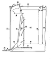
- An embodiment of the invention will now be described by way of example only with reference to the accompanying drawing which is a diagrammatic sectional view of the oven/grill cavity of the top small oven of a free standing double oven cooker.
- In the drawing an oven/
grill chamber 10 overlies amain oven chamber 12 and is defined byfloor 14,rear wall 16roof 18 and side walls. A front opening drop downdoor 20 is hinged to the front of the oven/grill chamber and a radiant ring or glass-ceramic cooking hob 22 is fitted above the grill-oven 18. The cooker is free-standing but is particularly adapted for use with built-in kitchen units. For this purpose thehob 22 stands at standard worktop height and nothing projects above it except for a small splash-back 24 intended to be fitted to the wall. Acontrol chamber 26 is located at the front of the cooker between thehob 22 and thedoor 20 which it overlies and in thechamber 26 are fitted electrical cooker controls 28. It will be noted that the cooker control panel is angled away from the opening to reduce the proportion of hot air from the grill chamber that encounters thecontrols 28 and to improve control visibility. - As will be observed the
roof 18 of the cooker slopes rearwardly and upwardly and there is aremovable deflector plate 30 that is slideably supported underneath theroof 18. Therear wall 16. androof 18 lead to anexhaust duct 32 which may be the full width of the oven or only part width and which opens to the rear of the cooker above thehob 22. Advantageously avent pipe 34 from thelower oven 12 passes behind therear wall 16 and also opens into theexhaust duct 32. When thegrill heating element 36 is on, there is a chimney-like flow of hot air towards the rear of the oven/grill as indicated by the arrows, thedeflector 30 being spaced from the rear ofexhaust duct 32. When the grill-oven is being used for roasting, theplate 30 is slid rearwardly (dotted lines) so that it occludes theexhaust duct 32 except at a small opening at its rear edge whereby there is a diminished area of flow from grill/oven 10 up thechimney 32.
Claims (6)
Applications Claiming Priority (2)
| Application Number | Priority Date | Filing Date | Title |
|---|---|---|---|
| GB08319572A GB2143633B (en) | 1983-07-20 | 1983-07-20 | Improvements in or relating to cookers |
| GB8319572 | 1983-07-20 |
Publications (2)
| Publication Number | Publication Date |
|---|---|
| EP0132364A2 true EP0132364A2 (en) | 1985-01-30 |
| EP0132364A3 EP0132364A3 (en) | 1986-07-30 |
Family
ID=10546009
Family Applications (1)
| Application Number | Title | Priority Date | Filing Date |
|---|---|---|---|
| EP84304850A Withdrawn EP0132364A3 (en) | 1983-07-20 | 1984-07-17 | Improvements in or relating to cookers |
Country Status (2)
| Country | Link |
|---|---|
| EP (1) | EP0132364A3 (en) |
| GB (1) | GB2143633B (en) |
Cited By (5)
| Publication number | Priority date | Publication date | Assignee | Title |
|---|---|---|---|---|
| US6104004A (en) * | 1997-04-10 | 2000-08-15 | Atd Corporation | Electric barbecue grill |
| US6276356B1 (en) | 1998-07-09 | 2001-08-21 | Atd Corporation | Portable gas grill |
| WO2013098251A1 (en) * | 2011-12-30 | 2013-07-04 | Arcelik Anonim Sirketi | An oven comprising an exhaust duct |
| US20150075513A1 (en) * | 2013-09-19 | 2015-03-19 | General Electric Company | Oven Range Appliance and a Cooling Assembly for the Same |
| EP4336104A1 (en) * | 2022-09-09 | 2024-03-13 | Whirlpool Corporation | Cooking appliance comprising a nozzle apparatus |
Families Citing this family (1)
| Publication number | Priority date | Publication date | Assignee | Title |
|---|---|---|---|---|
| GB2494866B (en) * | 2011-09-19 | 2014-01-29 | Basic Holdings | Cooking appliance |
Citations (3)
| Publication number | Priority date | Publication date | Assignee | Title |
|---|---|---|---|---|
| US2622582A (en) * | 1949-04-12 | 1952-12-23 | Tappan Stove Co | Ventilating and cooling means for cooking ranges |
| DE8015232U1 (en) * | 1980-06-07 | 1980-11-13 | Neff - Werke, Carl Neff Gmbh, 7518 Bretten | FRYING AND OVEN |
| GB2054834A (en) * | 1979-08-03 | 1981-02-18 | Nibelle P | Cooker |
Family Cites Families (2)
| Publication number | Priority date | Publication date | Assignee | Title |
|---|---|---|---|---|
| GB533223A (en) * | 1939-08-04 | 1941-02-10 | Simplex Electric Co Ltd | Improvements in or relating to domestic cooking apparatus |
| GB889429A (en) * | 1959-12-04 | 1962-02-14 | Radiation Ltd | Improvements in or relating to cooker ovens |
-
1983
- 1983-07-20 GB GB08319572A patent/GB2143633B/en not_active Expired
-
1984
- 1984-07-17 EP EP84304850A patent/EP0132364A3/en not_active Withdrawn
Patent Citations (3)
| Publication number | Priority date | Publication date | Assignee | Title |
|---|---|---|---|---|
| US2622582A (en) * | 1949-04-12 | 1952-12-23 | Tappan Stove Co | Ventilating and cooling means for cooking ranges |
| GB2054834A (en) * | 1979-08-03 | 1981-02-18 | Nibelle P | Cooker |
| DE8015232U1 (en) * | 1980-06-07 | 1980-11-13 | Neff - Werke, Carl Neff Gmbh, 7518 Bretten | FRYING AND OVEN |
Cited By (5)
| Publication number | Priority date | Publication date | Assignee | Title |
|---|---|---|---|---|
| US6104004A (en) * | 1997-04-10 | 2000-08-15 | Atd Corporation | Electric barbecue grill |
| US6276356B1 (en) | 1998-07-09 | 2001-08-21 | Atd Corporation | Portable gas grill |
| WO2013098251A1 (en) * | 2011-12-30 | 2013-07-04 | Arcelik Anonim Sirketi | An oven comprising an exhaust duct |
| US20150075513A1 (en) * | 2013-09-19 | 2015-03-19 | General Electric Company | Oven Range Appliance and a Cooling Assembly for the Same |
| EP4336104A1 (en) * | 2022-09-09 | 2024-03-13 | Whirlpool Corporation | Cooking appliance comprising a nozzle apparatus |
Also Published As
| Publication number | Publication date |
|---|---|
| GB8319572D0 (en) | 1983-08-24 |
| GB2143633B (en) | 1987-01-14 |
| GB2143633A (en) | 1985-02-13 |
| EP0132364A3 (en) | 1986-07-30 |
Similar Documents
| Publication | Publication Date | Title |
|---|---|---|
| US6362458B1 (en) | Food grilling system for oven cavity with byproduct removal | |
| US6761159B1 (en) | Exhaust cooling system for a cooking appliance | |
| US6943324B2 (en) | Combination heating system for a cooking appliance | |
| US4021642A (en) | Oven exhaust system for range with solid cooktop | |
| EP2918917B1 (en) | Home cooking appliance | |
| CN102239365B (en) | Cooktop with forced convection cooling | |
| US6729323B1 (en) | Air-inlet assembly for a gas cooking appliance | |
| US5044352A (en) | Large-burner stove with recessed burner well | |
| CA2475035C (en) | Combination radiant/convection gas cooking appliance | |
| US3328560A (en) | Recirculating venting system for domestic oven | |
| EP0132364A2 (en) | Improvements in or relating to cookers | |
| US3939817A (en) | Oven door handle construction | |
| CA2422169C (en) | Gas cooking appliance with louvered burner baffle | |
| KR100700771B1 (en) | Oven range with sliding type backgard | |
| US3404673A (en) | Stove with waist-high broiler | |
| JP2002280155A (en) | Cooking apparatus | |
| EP1972856B1 (en) | Cooking appliance | |
| US11378281B2 (en) | Home appliance having a low back rear vent trim | |
| CN218606239U (en) | Multifunctional outdoor cooking appliance | |
| KR200197578Y1 (en) | Bottom plate of combined hood and microwave range | |
| GB1601690A (en) | Fan assisted grill oven | |
| JPH0748006B2 (en) | Cooking device | |
| EP0318310A1 (en) | Improvements relating to cookers | |
| JPS609603Y2 (en) | oven toaster | |
| JPH0684829B2 (en) | Exhaust device for cooking |
Legal Events
| Date | Code | Title | Description |
|---|---|---|---|
| PUAI | Public reference made under article 153(3) epc to a published international application that has entered the european phase |
Free format text: ORIGINAL CODE: 0009012 |
|
| AK | Designated contracting states |
Designated state(s): DE FR IT |
|
| PUAL | Search report despatched |
Free format text: ORIGINAL CODE: 0009013 |
|
| RHK1 | Main classification (correction) |
Ipc: F24C 15/20 |
|
| AK | Designated contracting states |
Kind code of ref document: A3 Designated state(s): DE FR IT |
|
| 17P | Request for examination filed |
Effective date: 19860722 |
|
| 17Q | First examination report despatched |
Effective date: 19861124 |
|
| STAA | Information on the status of an ep patent application or granted ep patent |
Free format text: STATUS: THE APPLICATION IS DEEMED TO BE WITHDRAWN |
|
| 18D | Application deemed to be withdrawn |
Effective date: 19890421 |
|
| RIN1 | Information on inventor provided before grant (corrected) |
Inventor name: WINCHESTER, MICHAEL FRANCIS JOSEPH |