WO2016117562A1 - Metal ion detection method, analyte detection method, electrode substrate, and detection kit - Google Patents
Metal ion detection method, analyte detection method, electrode substrate, and detection kit Download PDFInfo
- Publication number
- WO2016117562A1 WO2016117562A1 PCT/JP2016/051451 JP2016051451W WO2016117562A1 WO 2016117562 A1 WO2016117562 A1 WO 2016117562A1 JP 2016051451 W JP2016051451 W JP 2016051451W WO 2016117562 A1 WO2016117562 A1 WO 2016117562A1
- Authority
- WO
- WIPO (PCT)
- Prior art keywords
- working electrode
- electrode
- metal
- current
- test substance
- Prior art date
Links
Images


Classifications
-
- G—PHYSICS
- G01—MEASURING; TESTING
- G01N—INVESTIGATING OR ANALYSING MATERIALS BY DETERMINING THEIR CHEMICAL OR PHYSICAL PROPERTIES
- G01N27/00—Investigating or analysing materials by the use of electric, electrochemical, or magnetic means
- G01N27/26—Investigating or analysing materials by the use of electric, electrochemical, or magnetic means by investigating electrochemical variables; by using electrolysis or electrophoresis
- G01N27/416—Systems
- G01N27/4166—Systems measuring a particular property of an electrolyte
- G01N27/4168—Oxidation-reduction potential, e.g. for chlorination of water
-
- G—PHYSICS
- G01—MEASURING; TESTING
- G01N—INVESTIGATING OR ANALYSING MATERIALS BY DETERMINING THEIR CHEMICAL OR PHYSICAL PROPERTIES
- G01N27/00—Investigating or analysing materials by the use of electric, electrochemical, or magnetic means
- G01N27/26—Investigating or analysing materials by the use of electric, electrochemical, or magnetic means by investigating electrochemical variables; by using electrolysis or electrophoresis
- G01N27/416—Systems
- G01N27/42—Measuring deposition or liberation of materials from an electrolyte; Coulometry, i.e. measuring coulomb-equivalent of material in an electrolyte
-
- G—PHYSICS
- G01—MEASURING; TESTING
- G01N—INVESTIGATING OR ANALYSING MATERIALS BY DETERMINING THEIR CHEMICAL OR PHYSICAL PROPERTIES
- G01N27/00—Investigating or analysing materials by the use of electric, electrochemical, or magnetic means
- G01N27/26—Investigating or analysing materials by the use of electric, electrochemical, or magnetic means by investigating electrochemical variables; by using electrolysis or electrophoresis
- G01N27/28—Electrolytic cell components
- G01N27/30—Electrodes, e.g. test electrodes; Half-cells
- G01N27/327—Biochemical electrodes, e.g. electrical or mechanical details for in vitro measurements
- G01N27/3275—Sensing specific biomolecules, e.g. nucleic acid strands, based on an electrode surface reaction
- G01N27/3277—Sensing specific biomolecules, e.g. nucleic acid strands, based on an electrode surface reaction being a redox reaction, e.g. detection by cyclic voltammetry
-
- G—PHYSICS
- G01—MEASURING; TESTING
- G01N—INVESTIGATING OR ANALYSING MATERIALS BY DETERMINING THEIR CHEMICAL OR PHYSICAL PROPERTIES
- G01N27/00—Investigating or analysing materials by the use of electric, electrochemical, or magnetic means
- G01N27/26—Investigating or analysing materials by the use of electric, electrochemical, or magnetic means by investigating electrochemical variables; by using electrolysis or electrophoresis
- G01N27/416—Systems
- G01N27/48—Systems using polarography, i.e. measuring changes in current under a slowly-varying voltage
-
- G—PHYSICS
- G01—MEASURING; TESTING
- G01N—INVESTIGATING OR ANALYSING MATERIALS BY DETERMINING THEIR CHEMICAL OR PHYSICAL PROPERTIES
- G01N33/00—Investigating or analysing materials by specific methods not covered by groups G01N1/00 - G01N31/00
- G01N33/48—Biological material, e.g. blood, urine; Haemocytometers
- G01N33/50—Chemical analysis of biological material, e.g. blood, urine; Testing involving biospecific ligand binding methods; Immunological testing
- G01N33/53—Immunoassay; Biospecific binding assay; Materials therefor
- G01N33/543—Immunoassay; Biospecific binding assay; Materials therefor with an insoluble carrier for immobilising immunochemicals
- G01N33/54313—Immunoassay; Biospecific binding assay; Materials therefor with an insoluble carrier for immobilising immunochemicals the carrier being characterised by its particulate form
-
- G—PHYSICS
- G01—MEASURING; TESTING
- G01N—INVESTIGATING OR ANALYSING MATERIALS BY DETERMINING THEIR CHEMICAL OR PHYSICAL PROPERTIES
- G01N33/00—Investigating or analysing materials by specific methods not covered by groups G01N1/00 - G01N31/00
- G01N33/48—Biological material, e.g. blood, urine; Haemocytometers
- G01N33/50—Chemical analysis of biological material, e.g. blood, urine; Testing involving biospecific ligand binding methods; Immunological testing
- G01N33/53—Immunoassay; Biospecific binding assay; Materials therefor
- G01N33/543—Immunoassay; Biospecific binding assay; Materials therefor with an insoluble carrier for immobilising immunochemicals
- G01N33/54366—Apparatus specially adapted for solid-phase testing
- G01N33/54373—Apparatus specially adapted for solid-phase testing involving physiochemical end-point determination, e.g. wave-guides, FETS, gratings
- G01N33/5438—Electrodes
-
- G—PHYSICS
- G01—MEASURING; TESTING
- G01N—INVESTIGATING OR ANALYSING MATERIALS BY DETERMINING THEIR CHEMICAL OR PHYSICAL PROPERTIES
- G01N33/00—Investigating or analysing materials by specific methods not covered by groups G01N1/00 - G01N31/00
- G01N33/48—Biological material, e.g. blood, urine; Haemocytometers
- G01N33/50—Chemical analysis of biological material, e.g. blood, urine; Testing involving biospecific ligand binding methods; Immunological testing
- G01N33/53—Immunoassay; Biospecific binding assay; Materials therefor
- G01N33/543—Immunoassay; Biospecific binding assay; Materials therefor with an insoluble carrier for immobilising immunochemicals
- G01N33/551—Immunoassay; Biospecific binding assay; Materials therefor with an insoluble carrier for immobilising immunochemicals the carrier being inorganic
- G01N33/553—Metal or metal coated
Definitions
- the present invention relates to a metal ion detection method, a test substance detection method, an electrode substrate, and a detection kit.
- Patent Document 1 describes a method of measuring silver ions or a test substance using an electrochemical measurement method.
- the silver ion measuring method described in Patent Document 1 is performed as follows. First, silver ions contained in a sample containing silver ions are electrochemically deposited on the working electrode. Next, the presence or concentration of silver ions is measured by measuring the current when electrochemically oxidizing the deposited silver.
- the measuring method of the to-be-tested substance described in patent document 1 is performed as follows. First, using a biological interaction, an amount of silver fine particles corresponding to the amount of the test substance is accumulated near the surface of the working electrode. Next, the accumulated silver fine particles are electrochemically oxidized and eluted. The eluted silver ions are reduced and deposited on the working electrode surface. Thereafter, the presence or concentration of the test substance is detected by measuring the current when electrochemically oxidizing the deposited silver.
- the present invention can detect a metal ion or a test substance with high detection sensitivity, a metal ion detection method and a test substance detection method, an electrode substrate for use in these methods, and a test substance detection kit I will provide a.
- the S / N ratio value of the ratio of signal to noise
- the linearity may be poor in the relationship between the signal and the concentration of silver ion or test substance.
- the present inventors applied a reduction potential to a portion having an area smaller than that of a portion to which an oxidation potential was applied in order to generate metal ions, thereby depositing metal. As a result, the present inventors have found that, for example, a large S / N ratio can be obtained even when the concentration of the metal ion or the test substance in the sample is low.
- the present inventors can obtain excellent linearity in relation to the signal and the concentration of the metal ion or the test substance even when the concentration of the metal ion or the test substance in the sample is low, for example. I found out.
- the present invention has been made based on these findings.
- One aspect of the present invention is an immobilization step of immobilizing a complex containing a test substance and metal particles on the surface of a working electrode of an electrode substrate including a working electrode and a counter electrode.
- Another aspect of the present invention is a composite comprising a test substance and metal particles on the first working electrode of the electrode substrate including the first working electrode, the second working electrode, and the counter electrode and on the surface of the second working electrode.
- Immobilization process An ionization step of generating metal ions from metal particles in the complex immobilized on the first working electrode and the second working electrode by applying an oxidation potential to the first working electrode and the second working electrode; A deposition step for depositing metal generated from metal ions on the surface of the first working electrode by applying a reduction potential to the first working electrode without applying a reduction potential to the second working electrode, and depositing in the deposition step
- a measuring step of measuring a current, voltage or charge caused by the metal to be detected.
- a sample containing metal ions is brought into contact with the surface of a working electrode of an electrode substrate including a working electrode and a counter electrode, and a reduction potential is applied to the working electrode to generate the metal ions.
- In the working electrode by applying a reduction potential to a portion having an area smaller than the area of the portion to which the oxidation potential is applied, a second precipitation that deposits a metal generated from the metal ion on the surface of the portion to which the reduction potential is applied.
- Still another aspect of the present invention is to apply a reduction potential to the working electrode by bringing a sample containing metal ions into contact with the surface of the working electrode of the electrode substrate including the first working electrode, the second working electrode, and the counter electrode.
- a first deposition step of depositing metal generated from metal ions on the surfaces of the first working electrode and the second working electrode An ionization step of generating metal ions from the metal deposited in the first deposition step by applying an oxidation potential to the first working electrode and the second working electrode;
- a method of detecting metal ions comprising: measuring a current, voltage or charge caused by a metal deposited in the process; and measuring a current, voltage or charge.
- Another aspect of the present invention includes a working electrode and a counter electrode, the working electrode including a portion for generating a metal ion and a portion for depositing a metal after the generation of the metal ion.
- Another aspect of the present invention includes a first working electrode that includes a working electrode and a counter electrode, wherein the working electrode is applied with an oxidation potential and a reduction potential after the application of the oxidation potential, and the application of the oxidation potential. And a second working electrode to which the reduction potential is not applied after the oxidation potential is applied, and an electrode substrate for use in the above-described test substance detection method or metal ion detection method.
- test substance detection kit including the electrode substrate described above and a reagent containing metal particles.
- a metal ion detection method and a test substance detection method capable of detecting a metal ion or a test substance with high detection sensitivity, an electrode substrate for use in these methods, and a test substance A detection kit can be provided.
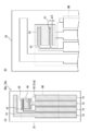
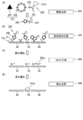
- FIG. It is a perspective view which shows a detection apparatus. It is a block diagram which shows the structure of the detection apparatus shown by FIG. (A) is a front view which shows an example of an electrode substrate, (B) is the elements on larger scale of the electrode substrate shown by (A). (A) is a front view which shows the modification of an electrode substrate, (B) is the elements on larger scale of the electrode substrate shown by (A). (A) is a front view which shows the modification of an electrode substrate, (B) is the elements on larger scale of the electrode substrate shown by (A). It is process explanatory drawing which shows an example of the process sequence of the detection method of a metal ion. It is process explanatory drawing which shows the modification of the process sequence of the detection method of a metal ion.
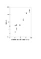
- Example 4 the concentration of the test substance in the sample and the silver nanoparticles in the labeled complex bound to the test substance contained in the sample It is a graph which shows the result of having investigated the relationship with an electric current.
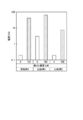
- Example 4 and Comparative Example 6 using the electrode substrate shown in FIG. 3, the concentration of the test substance in the sample and the silver nanoparticles in the labeled complex bound to the test substance contained in the sample It is a graph which shows the result of having investigated the relationship with an electric current.
- Example 5 and Comparative Example 7 using the electrode substrate shown in FIG. 5, a graph showing the results of detecting the current caused by silver nanoparticles in the labeled complex bound to the test substance contained in the sample is there.
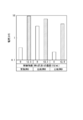
- Example 6 Comparative Example 8 and Comparative Example 9 using the electrode substrate shown in FIG. 4, the result of detecting the current caused by the silver nanoparticles in the labeled complex bound to the test substance contained in the sample It is a graph which shows.
- X or more means including a value of X and a value larger than X.
- Y or less means that the value of Y and a value smaller than Y are included.
- the description of numerical ranges by endpoints includes all numbers and rational numbers included within each range as well as the endpoints being described.
- test substance means a substance other than metal ions.
- test substance include, but are not limited to, nucleic acids, proteins, peptides, sugar chains, antigens, antibodies, and the like.
- the detection device 10 includes a substrate receiving unit 11 into which an electrode substrate 30 is inserted, and a display 12 that displays a detection result.
- the detection device 10 includes a display 12, an electrical measurement device 13, a power source 14, an A / D conversion unit 15, and a control unit 16.
- the electrical measuring device 13 measures current, voltage, or electric charge caused by the deposited metal.
- the power supply 14 applies a predetermined potential to the electrodes provided on the electrode substrate 30.
- the A / D converter 15 digitally converts the current value, voltage value, or charge value measured by the electrical measurement device 13.
- the control unit 16 includes a CPU (Central Processing Unit), a ROM (Read Only Memory), and a RAM (Random Access). Memory) and the like.
- the control unit 16 controls operations of the display 12, the electrical measurement device 13, and the power supply 14.
- the control part 16 controls application of the oxidation potential and the reduction potential to the working electrode of the electrode substrate, as will be described later.
- control unit 16 is based on a calibration curve indicating a relationship between a current value, a voltage value or a charge value created in advance from the current value digitally converted by the A / D conversion unit 15 and the amount of metal, By estimating the amount of metal, the amount of metal ions or the amount of a test substance can be calculated.
- the display 12 displays information such as the amount of metal ions or the amount of test substance calculated by the control unit 16.
- the electrode substrate according to the present embodiment includes a working electrode and a counter electrode.
- the working electrode includes a part for generating metal ions (hereinafter also referred to as “ion generation part”) and a part for precipitation of metal after generation of metal ions (hereinafter also referred to as “metal precipitation part”). Including.
- the working electrode is configured such that the area of the metal deposition part is smaller than the area of the ion generation part. Therefore, compared to the case where metal ions are generated on the entire working electrode and metal deposition after the metal ions are generated, the current, voltage or charge is measured only on a part of the working electrode, so that noise is reduced.
- the metal ions are accumulated in a small area portion (metal precipitation portion) to obtain metal. It can be deposited. Therefore, it is possible to obtain a signal equivalent to the case where metal ion generation and metal deposition after metal ion generation are performed on the entire working electrode. Therefore, the S / N ratio is improved.
- an oxidation-reduction potential application unit and an oxidation potential application unit may be provided.
- An oxidation potential is applied to the oxidation-reduction potential application unit to generate metal ions, and a reduction potential is applied to deposit metal after the generation of metal ions.
- An oxidation potential is applied to the oxidation potential application unit to generate metal ions, but no reduction potential is applied after the metal ions are generated.
- the oxidation-reduction potential application unit and the oxidation potential application unit are electrically insulated from each other.
- the ion generation unit includes an oxidation-reduction potential application unit and an oxidation potential application unit.
- the metal deposition part is composed of an oxidation-reduction potential application part.
- the electrode substrate 30 a includes a substrate body 31.
- a first working electrode 41, a second working electrode 42, a counter electrode 51, a reference electrode 61, and electrode leads 71, 72, 73, 74 are formed on the surface of the substrate body 31.
- the resist insulating film 80 is disposed so that the first working electrode 41, the second working electrode 42, the counter electrode 51, and the reference electrode 61 are exposed and a part of the electrode leads 71, 72, 73, 74 is covered. . Thereby, the contact of the sample to each electrode is maintained, and the leakage of the sample to each electrode lead is suppressed.
- the first working electrode 41 is configured integrally with the electrode lead 71.
- the first working electrode 41 is an exposed portion that is not covered with the resist insulating film 80.
- the 1st working electrode 41 consists of two parts shown by A1.
- the second working electrode 42 is configured integrally with the electrode lead 72.
- the second working electrode 42 is an exposed portion that is not covered with the resist insulating film 80. In this part, metal ionization and the like are performed.
- the first working electrode 41 and the second working electrode 42 are hatched.
- the first working electrode 41 and the second working electrode 42 are arranged on one side of the substrate body 31 (upper side in FIG. 3A).
- the electrode lead 71 extends from the first working electrode 41 toward the other side of the substrate body 31 (the lower side in FIG. 3A).
- the electrode lead 72 extends from the second working electrode 42 toward the other side of the substrate body 31 (the lower side in FIG. 3).
- the counter electrode 51 is disposed on the substrate body 31 outside the first working electrode 41 and the second working electrode 42 (on the upper side of the first working electrode 41 and the second working electrode 42 in FIG. 3A). Yes.
- the electrode lead 73 extends from the counter electrode 51 toward the other side of the substrate body 31 (the lower side in FIG. 3), bypassing the first working electrode 41, the second working electrode 42 and the reference electrode 61.
- the reference electrode 61 is disposed at a position facing the counter electrode 51 with the first working electrode 41 and the second working electrode 42 interposed therebetween.
- the electrode lead 74 extends from the reference electrode 61 toward the other side of the substrate body 31 (the lower side in FIG. 3).
- the electrode leads 71, 72, 73, 74 are arranged in parallel with each other on the other side (lower side in FIG. 3) of the substrate body 31.
- both the first working electrode 41 and the second working electrode 42 are ion generating parts, and the first working electrode 41 is a metal deposition part.
- the first working electrode 41 is an oxidation-reduction potential application unit.
- the first working electrode 41 is applied with an oxidation potential and a reduction potential after the oxidation potential is applied.
- the second working electrode 42 is an oxidation potential application unit. Although the oxidation potential is applied to the second working electrode 42, the reduction potential is not applied after the oxidation potential is applied.
- the first working electrode 41 and the second working electrode 42 are electrically insulated from each other by a gap of a distance ⁇ G.
- A1 / (A1 + A2) is usually preferably 1 ⁇ 2 or less, more preferably 1/10 or less, from the viewpoint of improving the S / N ratio.
- the lower limit value of A1 / (A1 + A2) can be appropriately determined according to the limit of formation accuracy by the method of forming the electrode on the surface of the substrate body, the use of the electrode substrate, and the like.
- “All working electrodes” means a concept including both the first working electrode and the second working electrode.
- the movement time of the metal ions to the first working electrode 41 is shortened as the distance ⁇ G between the first working electrode 41 and the second working electrode 42 is smaller. Therefore, shortening of the operation time required for detection of a metal ion or a test substance is expected.
- the distance ⁇ G between the first working electrode 41 and the second working electrode 42 is usually preferably 100 ⁇ m or less, more preferably 50 ⁇ m or less, from the viewpoint of shortening the operation time required for detection of metal ions or a test substance. is there.
- the lower limit value of the distance ⁇ G between the first working electrode 41 and the second working electrode 42 can be appropriately determined according to the limit of the electrode forming method on the surface of the substrate body, the use of the electrode substrate, and the like. it can.
- the second working electrode 42 has a comb shape.
- the first working electrode 41 is disposed so as to be inserted into a gap portion of the comb teeth of the second working electrode.
- metal ions can be easily moved between the first working electrode 41 and the second working electrode 42.
- manufacture is also easy.
- Each of the first working electrode 41 and the second working electrode 42 may have a polygonal shape, a rectangular shape, a disk shape, an elliptical shape, or the like.
- the number of comb teeth in the comb tooth portion of the second working electrode is not particularly limited. In FIG. 3, the number of comb teeth in the comb tooth portion of the second working electrode 42 is three. In FIG. 4, the number of comb teeth in the comb tooth portion of the second working electrode 44 is two. In FIG. 5, the number of comb teeth in the comb tooth portion of the second working electrode 46 is four.
- the first working electrode indicated by A1 in each of FIGS. 3 (B), 4 (B) and 5 (B) is arranged to be inserted into all the gaps of the plurality of comb teeth of the second working electrode. It is preferable.
- one or more electrodes functioning as the first working electrode can be provided on the surface of the substrate body 31. Further, one or more electrodes functioning as the second working electrode can be provided on the surface of the substrate body 31.
- the first working electrode 41 and the second working electrode 42 are each composed of a thin film having conductivity.
- the conductive thin film is mainly composed of a conductive material.
- the conductive material include carbon materials such as graphite, glassy carbon, pyrolytic graphite, carbon paste, carbon fiber, carbon nanotube, and graphene; metal materials such as gold and platinum; indium oxide doped with tin (ITO) And oxide semiconductors such as tin oxide (FTO) doped with fluorine, but are not particularly limited.
- the first working electrode 41 and the second working electrode 42 are made of a composite base material in which a conductive layer made of a conductive material is provided on the surface of a non-conductive base material made of a non-conductive material such as glass or plastic. It may be configured.
- the thickness of the thin film is desirably determined as appropriate according to the use of the electrode substrate.
- a capture substance that binds to the test substance is immobilized on the surfaces of the first working electrode 41 and the second working electrode.
- the capture substance include, but are not limited to, nucleic acids, proteins, peptides, sugar chains, antibodies, and nanostructures having specific recognition ability. It is desirable that the capture substance is appropriately determined according to the type of the test substance.
- the test substance is a nucleic acid
- a nucleic acid probe that hybridizes to the nucleic acid, an antibody against the nucleic acid, or the like can be used as the capture substance.
- an antibody can be used as the capture substance.
- the test substance is a sugar chain
- a lectin against the sugar chain, an antibody against the sugar chain, or the like can be used as the capture substance.
- an antigen an antibody against the antigen can be used as the capture substance.
- the amount of the capturing substance per unit area immobilized on the surfaces of the first working electrode 41 and the second working electrode 42 may be an amount sufficient to capture the test substance.
- the substrate body 31 has a rectangular shape.
- the shape of the substrate body 31 is not particularly limited, and may be a polygonal shape, a disk shape, or the like.
- the material constituting the substrate body 31 examples include, but are not limited to, plastics such as polyethylene terephthalate, polyimide, and glass epoxy; and inorganic materials such as glass and metal. It is desirable that the thickness of the substrate body 31 is appropriately determined according to the use of the electrode substrate.
- the counter electrode 51 is composed of a conductive thin film.
- the conductive thin film is mainly composed of a conductive material.
- the conductive material used for the counter electrode 51 is the same as the conductive material used for the first working electrode 41 and the second working electrode 42.
- the thickness of the thin film constituting the counter electrode 51 is desirably determined as appropriate according to the use of the electrode substrate.
- the reference electrode 61 is made of a conductive thin film.
- the conductive thin film is mainly composed of a conductive material.
- the conductive material include metals such as gold, silver, copper, carbon, platinum, palladium, chromium, aluminum, and nickel; alloys containing at least one of the metals; metal halides such as metal chlorides; There are no particular limitations.
- the reference electrode 61 may be composed of a composite substrate in which a conductive layer made of a conductive material is provided on the surface of a nonconductive substrate made of a nonconductive material such as glass, glass epoxy, or plastic.
- the reference electrode 61 include, for example, a silver-silver chloride electrode, and a calomel electrode using mercury and mercury chloride, but are not particularly limited.
- the thickness of the thin film constituting the reference electrode 61 is desirably determined as appropriate according to the use of the electrode substrate.
- the reference electrode 61 is provided on the surface of the substrate body 31. Therefore, according to the electrode substrate 30a according to the present embodiment, when measuring a large current, it is possible to suppress the influence of the voltage drop and stabilize the voltage applied to the first working electrode 41 and the second working electrode 42. it can.
- the reference electrode 61 may not be provided on the surface of the substrate body 31.
- the counter electrode 51 is used as the reference electrode 61. You may also serve.
- the electrode substrate according to the present embodiment can be manufactured by, for example, a method including the following steps.
- (I) A step of forming a conductive thin film on the surface of the substrate body so as to form a pattern of a working electrode, a counter electrode, and optionally a reference electrode.
- (II) If necessary, a capture substance is fixed on the surface of the working electrode.
- (III) A step of performing blocking treatment on the working electrode surface, if necessary.
- step (I) the formation of the conductive thin film can be performed by a method such as a screen printing method or a photolithography method.
- step (II) may be performed.
- the capture substance can be immobilized, for example, via a binding group that binds to a conductive material or the like constituting the working electrode.
- the linking group include, but are not limited to, a thiol group, a hydroxyl group, a phosphoric acid group, a carboxyl group, a carbonyl group, an aldehyde group, a sulfonic acid group, and an amino group.
- the capture substance may be immobilized by, for example, physical adsorption.
- step (III) it is desirable to perform step (III) from the viewpoint of suppressing nonspecific adsorption of a substance other than the test substance (hereinafter also referred to as “contaminant substance”) to the working electrode.
- the blocking treatment can be performed by bringing a blocking agent into contact with the working electrode. Any blocking agent may be used as long as it suppresses non-specific adsorption of contaminants to the working electrode. Examples of the blocking agent include, but are not particularly limited to, a solution in which any one or more of bovine serum albumin, skim milk powder, casein, and gelatin are dissolved in a solvent.
- the obtained electrode substrate can be appropriately washed and used in order to remove excess blocking agent.
- Metal ion detection method applies a reduction potential to the working electrode by bringing the sample containing the metal ion into contact with the surface of the working electrode of the electrode substrate including the working electrode and the counter electrode.
- a first precipitation step for precipitating the metal generated from the metal ions on the surface of the working electrode An ionization step of generating metal ions from the metal deposited in the first deposition step by applying an oxidation potential to the working electrode;
- a reduction potential to a portion having a surface area smaller than the surface area of the portion to which the oxidation potential is applied, a second precipitation for depositing metal generated from the metal ions on the surface of the portion to which the reduction potential is applied
- measuring the current, voltage or charge resulting from the metal deposited in the deposition step and measuring the current, voltage or charge hereinafter referred to as “Method 1”.
- a working electrode including a first working electrode and a second working electrode can be used as the working electrode.
- An application of an oxidation potential and a reduction potential after application of the oxidation potential are performed on the first working electrode.
- an oxidation potential is applied to the second working electrode, a reduction potential is not applied after the oxidation potential is applied.
- Both the first working electrode and the second working electrode are ion generation parts, and the first working electrode is a metal deposition part.
- a metal is deposited on the first working electrode and the second working electrode in the first deposition step.
- an oxidation potential is applied to both the first working electrode and the second working electrode.
- the detection apparatus 10 shown in FIG. 1 can be used.
- detection of metal ions means quantification of metal ions; metal ions such as “strong positive (++)”, “weak positive (+)”, “negative ( ⁇ )”, etc. Semi-quantitative; a concept that includes qualitatively determining the presence or absence of metal ions.
- sample containing metal ions examples include, but are not limited to, river water, seawater, soil, food, and the like. These samples may be appropriately pretreated before being brought into contact with the working electrode. For example, soil and food can be dissolved and suspended in the electrolyte solution described below.
- metal ions include, but are not particularly limited to, transition metal ions such as lead ions, copper ions, mercury ions, cadmium ions, gold ions, platinum ions, silver ions, and zinc ions.
- transition metal ions such as lead ions, copper ions, mercury ions, cadmium ions, gold ions, platinum ions, silver ions, and zinc ions.
- lead ions, copper ions, mercury ions, cadmium ions, gold ions, and silver ions can be detected well.
- Transition metal ions can easily deposit and deposit a metal on the electrode surface by applying a negative potential to the electrode. Therefore, the transition metal ion can be detected by the method 1 according to the present embodiment.
- the metal is a metal that is deposited by reduction of metal ions.
- metal ions can be detected based on current, voltage, or charge (hereinafter referred to as “method 1-1”).
- “Other metal ions having the same properties as silver ions” are ions that can be easily oxidized (ionized) by applying a positive voltage to the electrodes, similarly to silver ions. Examples of other metal ions having the same properties as silver ions include lead ions, copper ions, mercury ions, cadmium ions, and zinc ions, but are not particularly limited.
- FIG. 6 is a cross-sectional explanatory view taken along the line AA of the first working electrode 43 and the second working electrode 44 in FIG. 4B.
- the first working electrode 43 is configured integrally with the electrode lead 71.
- the first working electrode 43 is an exposed portion that is not covered with the resist insulating film 80. In this portion, metal deposition, metal ionization, and the like are performed.
- the first working electrode 43 is indicated by A1.
- the second working electrode 44 is configured integrally with the electrode lead 72.
- the second working electrode 44 is an exposed portion that is not covered with the resist insulating film 80. In this part, metal ionization and the like are performed.
- the first working electrode 43 and the second working electrode 44 are hatched.
- the user applies the sample 201 containing silver ions 211a to the first working electrode 43, the second working electrode 44, the counter electrode 51 (not shown), and not shown. It adds to the electrode substrate 30b so that the exposed part of each reference electrode 61 may be covered.
- the user inserts the electrode substrate 30 into the substrate receiving portion 11 of the detection apparatus 10 shown in FIG.
- the electrode leads 71, 72, 73 and 74 of the electrode substrate 30 inserted into the detection device 10 are connected to the electrical measurement device 13 and the power source 14 of the detection device 10.
- the user applies a reduction potential to both the first working electrode 43 and the second working electrode 44.
- the user instructs the detection apparatus 10 to start a processing procedure. Accordingly, a predetermined reduction potential with reference to the reference electrode 61 is applied to both the first working electrode 43 and the second working electrode 44 by the power supply 14 of the detection device 10.
- the reduction potential is a potential at which a metal ion to be detected is reduced to generate a metal. Therefore, the reduction potential can be appropriately determined according to the type of metal ion.
- the metal ion is, for example, a silver ion
- the reduction potential is ⁇ 1.2 to 0 V on a silver / silver chloride basis.
- the metal ion is, for example, a copper ion
- the reduction potential is ⁇ 1.2 to ⁇ 0 V on a silver / silver chloride basis.
- Such a reduction potential may be kept constant during application, or may be changed over time.
- the application time of the reduction potential can be appropriately determined according to the application of the method 1 according to the present embodiment, the type of sample, the amount of metal ions contained in the sample, the type of metal ions, and the like.
- a reduction potential is applied to both the first working electrode 43 and the second working electrode 44.
- the silver ions 211a are reduced by both the first working electrode 43 and the second working electrode 44, and the surfaces of both the first working electrode 43 and the second working electrode 44 are reduced.
- Silver 211b can be deposited on top. Thereby, the silver 211b produced
- the cleaning solution include water; buffer solutions such as phosphate buffered saline and Tris buffered saline; electrolytes used in the ionization step S13, the second precipitation step S14, and the detection step S15 described later.
- the electrolyte used in the electrolytic solution include hydrochloric acid, sodium chloride, potassium chloride, sodium thiocyanate, and potassium thiocyanate, but are not particularly limited.
- the solvent used in the electrolytic solution include, but are not limited to, water; buffer solutions such as phosphate buffered saline and Tris buffered saline.
- the user performs electrolysis so as to cover the exposed portions of the first working electrode 43, the second working electrode 44, the counter electrode 51, and the reference electrode 61.
- the liquid is dropped and an oxidation potential is applied to both the first working electrode 43 and the second working electrode 44.
- a predetermined oxidation potential based on the reference electrode 61 is applied to both the first working electrode 43 and the second working electrode 44 by the power supply 14 of the detection apparatus 10.
- the electrolytic solution is the same as the electrolytic solution shown above.
- the oxidation potential is a potential at which metal is oxidized and metal ions are generated. Therefore, the oxidation potential can be appropriately determined according to the type of metal.
- the metal ion is, for example, a silver ion
- the oxidation potential is 1 to 2.5 V on a silver / silver chloride basis.
- the metal ion is, for example, a copper ion
- the oxidation potential is 0.8 to 2.0 V on a silver / silver chloride basis.
- Such an oxidation potential may be kept constant during application or may be changed over time. Further, the application time of the oxidation potential can be appropriately determined according to the use of the method 1 according to the present embodiment, the amount of metal, the type of sample, the type of metal, and the like.
- an oxidation potential is applied to both the first working electrode 43 and the second working electrode 44.
- the silver 211b is oxidized by both the first working electrode 43 and the second working electrode 44, and in the vicinity of both the first working electrode 43 and the second working electrode 44.
- Silver ions 211a can be generated from the silver 211b.
- the reduction potential and application time in the second precipitation step S14 are the same as the reduction potential and application time in the first precipitation step S12.
- the reduction potential is applied in the presence of an electrolytic solution.
- the electrolytic solution used in the second deposition step S14 is the same as the electrolytic solution used in the ionization step S13.
- a potential may be applied within a range in which the silver 211 b is not deposited on the second working electrode 44.
- the reduction potential is applied to a portion having an area smaller than the portion of the portion to which the oxidation potential is applied in order to generate the silver ions 211a in the ionization step S13, thereby depositing the silver 211b.
- the user uses the first current, voltage, or charge as the current, voltage, or charge caused by the silver 211b on the surface of the first working electrode 43 in the second deposition step S14.
- the current, voltage or charge generated when the silver 211b on the surface of the working electrode 43 is ionized is measured.
- a predetermined oxidation potential based on the reference electrode 61 is applied only to the first working electrode 43 by the power source 14 of the detection apparatus 10.
- the electric measuring device 13 measures the current, voltage or charge between the first working electrode 43 and the counter electrode 51 due to the silver 211b.
- the application of the oxidation potential is performed in the presence of an electrolytic solution.
- the electrolytic solution used in the detection step S15 is the same as the electrolytic solution used in the ionization step S13.
- examples of the method for measuring current, voltage or charge include, but are not limited to, a differential pulse voltammetry method, a cyclic voltammetry method, a chronoamperometry method, and the like.
- the amount of metal ions contained in a sample can be obtained based on a calibration curve created using a sample containing a known amount of metal ions.
- the calibration curve plots the relationship between the amount of metal ions and the current, voltage or charge resulting from the metal measured by performing each step of Method 1-1 using a sample containing a known amount of metal ions.
- metal ions are semi-quantified by Method 1-1, for example, a plurality of samples each containing a known amount of metal ions and a sample not containing metal ions are used, and only positive and negative determinations are made based on the concentration of metal ions. In addition, a sample determined to be positive can be further classified.
- the surface area of the first working electrode 43 used to measure the current, voltage, or charge resulting from the silver 211b is smaller than the surface area of all working electrodes. Therefore, in the method 1-1 according to the present embodiment, the current, voltage, or charge is measured using only a part of the working electrode. Thereby, compared with the case where metal ion production
- the method 1-1 according to the present embodiment excellent linearity can be obtained in the relationship between the silver ion concentration and the corresponding signal at a low concentration. Therefore, according to the method 1-1 according to the present embodiment, metal ions such as silver ions can be detected with high detection sensitivity.
- Metal ion detection method When detecting gold ions or other metal ions having the same properties as gold ions, in the measurement process, the current until the metal is deposited on the first working electrode in the deposition process, The voltage or charge is measured, and the metal ion can be detected based on the current change accompanying the deposition of the metal on the first working electrode, the application time of the reduction potential until the voltage change or the charge change occurs ( Hereinafter referred to as “Method 1-2”).
- “Other metal ions having the same properties as gold ions” are metal ions that are difficult to oxidize the deposited metal and require a large voltage, like gold ions. Examples of other metal ions having the same properties as gold ions include, but are not limited to, platinum ions.
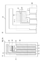
- FIG. 7 is a cross-sectional explanatory view taken along line AA of the first working electrode 43 and the second working electrode 44 in FIG. 4 (B).
- Method 1-1 uses a sample 201 containing silver ions 211a
- method 1-2 uses a sample 202 containing gold ions 221a.
- Method 1-1 the current, voltage or charge when the silver 211b deposited on the surface of the first working electrode 43 is ionized again is measured, and the silver ion 211a is detected based on the current, voltage or charge. To do.
- the current, voltage or charge when the gold 221b is deposited on the surface of the first working electrode 43 is measured, or the current change, voltage change or A point in which the change in charge is measured, and the gold ion 221a is detected based on the current, voltage or charge during the deposition of the gold 211b, the change in current accompanying the deposition of the gold 211b, the change in voltage or the change in charge.
- the user removes the sample 202 containing the gold ions 221a from the first working electrode 43 and the second working electrode 43. It is added to the electrode substrate 30b so as to cover the exposed portions of the working electrode 44, the counter electrode 51 (not shown), and the reference electrode 61 (not shown).
- the user applies a reduction potential to both the first working electrode 43 and the second working electrode 44.
- the reduction potential is ⁇ 1.0 to 0.5 V on a silver / silver chloride basis.
- the metal ion is, for example, platinum ion
- the reduction potential is ⁇ 1.0 to 0.2 V on the basis of silver / silver chloride.
- the application time of the reduction potential can be appropriately determined according to the use of the method 1-2 according to the present embodiment, the type of sample, the type of metal ion, and the like.
- a reduction potential is applied to both the first working electrode 43 and the second working electrode 44.
- gold 221b generated from the gold ions 221a contained in the sample 202 can be collected on both surfaces of the first working electrode 43 and the second working electrode 44. .
- the exposed portions of the first working electrode 43, the second working electrode 44, the counter electrode 51 (not shown), and the reference electrode 61 (not shown) are preferably washed with a washing liquid.
- the cleaning liquid used for the cleaning is the same as the cleaning liquid used in Method 1-1.
- the user applies an oxidation potential to both the first working electrode 43 and the second working electrode 44.
- the oxidation potential is 1.3 to 2.4 V on a silver / silver chloride basis.
- the metal ion is, for example, platinum ion
- the oxidation potential is 1.0 to 2.0 V on a silver / silver chloride basis.
- the application time of the oxidation potential can be appropriately determined according to the application of the method 1-2 according to the present embodiment, the type of sample, the type of metal, and the like.
- an oxidation potential is applied to both the first working electrode 43 and the second working electrode 44.
- the gold 221b is oxidized by both the first working electrode 43 and the second working electrode 44, and in the vicinity of both the first working electrode 43 and the second working electrode 44.
- Gold ions 221a can be generated from the gold 221b.
- the application of the oxidation potential is performed in the presence of an electrolytic solution. This is the same as the electrolytic solution used in Method 1-1.
- the reduction potential is not applied to the second working electrode 44, but only the first working electrode 43 is applied.
- a predetermined reduction potential based on the reference electrode 61 is applied only to the first working electrode 43 by the power source 14 of the detection apparatus 10.
- the electrical measuring device 13 measures the current, voltage or charge when the gold 221b is deposited on the surface of the first working electrode 43, or the deposition of the gold 221b on the first working electrode 43. Measure the current change, voltage change or charge change due to.
- the gold ion 221a is detected based on the current, voltage, or charge during the deposition of the gold 221b on the first working electrode, or the change in the current, the change in the voltage, or the change in the charge accompanying the deposition of the gold 221b.
- the reduction potential and application time in the detection step S24 are the same as the reduction potential and application time in the deposition step S22.
- the reduction potential is applied to the portion having an area smaller than the portion of the portion to which the oxidation potential is applied in order to generate the gold ions 221a in the ionization step S23, thereby depositing the gold 221b. Accordingly, as shown in FIG. 7D, gold 221b generated from the gold ions 221a generated in the ionization process can be accumulated and deposited by the first working electrode 43.
- the reduction potential is applied in the presence of an electrolytic solution. This is the same as the electrolytic solution used in Method 1-1.
- the current, voltage and charge during the deposition of the gold 221b in the detection step S24 and the current change, voltage change and charge change accompanying the deposition of the gold 221b are the same as the current, voltage or charge in the detection step S15 in the method 1-1. It can be measured by the same method as the above measuring method.
- the amount of current or charge that has flowed until the deposition of gold 221b on the surface of the first working electrode 43, the voltage required for the deposition of gold 221b, and the current value depending on the deposition are saturated. It is possible to use, as an index, the time required to do so.
- Method 1-2 determination of metal ions, semi-quantification of metal ions, and qualitative determination of the presence or absence of metal ions can be performed in the same manner as in Method 1-1.
- the surface area of the first working electrode 43 used to measure the current, voltage, or charge resulting from the gold 221b is smaller than the surface area of all working electrodes. Therefore, according to the method 1-2 according to the present embodiment, metal ions such as gold ions can be detected with high detection sensitivity as in the method 1-1.
- Test substance detection method The test substance detection method according to the present embodiment immobilizes a complex containing the test substance and metal particles on the surface of the working electrode of the electrode substrate including the working electrode and the counter electrode. Immobilization process, An ionization step of generating metal ions from metal particles in the complex immobilized on the working electrode by applying an oxidation potential to the working electrode; A deposition step of depositing a metal generated from metal ions on the surface of the portion to which the reduction potential is applied by applying a reduction potential to a portion having an area smaller than the area of the portion to which the oxidation potential is applied in the working electrode; and A measurement step of measuring a current, voltage or charge caused by the metal deposited in the deposition step (hereinafter referred to as “method 2”).
- a working electrode including a first working electrode and a second working electrode can be used as the working electrode.
- An application of an oxidation potential and a reduction potential after application of the oxidation potential are performed on the first working electrode.
- an oxidation potential is applied to the second working electrode, a reduction potential is not applied after the oxidation potential is applied.
- Both the first working electrode and the second working electrode are ion generation parts, and the first working electrode is a metal deposition part.
- the complex is immobilized on the first working electrode and on the surface of the second working electrode in the immobilization step.
- the ionization step by applying an oxidation potential to both the first working electrode and the second working electrode, metal ions from the metal particles in the composite immobilized on the first working electrode and the second working electrode Is generated. Furthermore, in the deposition step, a reduction potential is applied to the first working electrode without applying a reduction potential to the second working electrode, thereby depositing a metal generated from metal ions on the surface of the first working electrode.
- the detection apparatus 10 shown in FIG. 1 can be used.
- detection of a test substance means quantifying a test substance; “strong positive (++)”, “weak positive (+)”, “negative ( ⁇ )”, etc. This is a concept that includes semi-quantitating a test substance; qualitatively determining the presence or absence of a test substance.
- sample containing the test substance examples include, but are not limited to, specimens typified by whole blood, plasma, serum, urine, saliva, and the like; river water, seawater, soil, foods, and the like.
- metal particles examples include transition metal particles such as gold particles, silver particles, copper particles, lead particles, platinum particles and indium particles, composite particles of various metals such as gold-silver composite particles and gold-copper composite particles; cadmium sulfide. And quantum dots such as zinc sulfide (also referred to as “semiconductor particles”), but are not particularly limited.
- the particle diameter of the metal particles is preferably 5 nm or more, and more preferably 10 nm or more, from the viewpoint of obtaining a signal such as sufficient current, voltage, and electrification when the metal is deposited.
- the particle diameter of the metal particles is preferably 200 nm or less, more preferably 100 nm or less, from the viewpoint of improving the capture efficiency of the test substance and the labeling efficiency of the test substance.
- metal particles include not only spherical metal particles but also metal particles having a shape other than a spherical shape.
- the “particle diameter” refers to the diameter when the metal particle has a spherical shape, and refers to the average of the maximum diameter and the minimum diameter of the particle when the metal particle has a shape other than the spherical shape.
- the particle diameter of the metal particles can be determined by, for example, a light scattering method or microscopic observation.
- silver, other metal particles having the same properties as silver, or a method using quantum dots are used in the measurement step. Then, the current, voltage or charge generated when generating metal ions from the metal deposited on the surface of the first working electrode in the deposition step is measured. In this case, the test substance is detected based on the current, voltage or charge.
- “Another metal having properties similar to silver” is a metal that can easily form particles and can be easily oxidized (ionized) by applying an oxidation potential to an electrode, like silver. Examples of the metal having the same properties as silver include copper, lead, and indium, but are not particularly limited.
- the current, voltage, or charge generated when generating metal ions from the metal obtained from the metal ions constituting the quantum dots can be measured.
- the quantum dot is cadmium sulfide
- the current, voltage or charge generated when cadmium ions are generated from cadmium can be measured.
- the electric current, voltage, or electric charge which is generated when zinc ions are generated from zinc can be measured.
- the precipitation step In the method 2 in the present embodiment, in the method using gold or other metal particles having the same properties as gold as the metal particles (hereinafter also referred to as “method 2-2”), in the measurement step, the precipitation step The current, voltage or charge until the metal is deposited on the first working electrode is measured. In this case, the test substance is detected based on the application time of the reduction potential until the change of the current, the change of the voltage, or the change of the charge accompanying the deposition of the metal on the first working electrode.
- “Another metal having properties similar to gold” is a metal that can form particles as in gold and requires a large oxidation potential when oxidized on an electrode. Examples of other metals having the same properties as gold include platinum, but are not particularly limited.
- a binding substance that binds to the test substance is immobilized on the metal particles. It is preferable that the binding substance binds to a place different from the capture substance in the test substance.
- the binding substance is appropriately selected according to the type of the test substance.
- the test substance is a nucleic acid
- a nucleic acid probe that hybridizes to the nucleic acid, an antibody against the nucleic acid, a protein that binds to the nucleic acid, or the like can be used as the binding substance.
- the test substance is a protein or peptide
- an antibody against the protein, an antibody against the peptide, or the like can be used as the binding substance.
- the test substance is a sugar chain, a lectin against the sugar chain, an antibody against the sugar chain, or the like can be used as the binding substance.
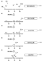
- FIG. 8 is a cross-sectional explanatory view taken along line AA of the first working electrode 43 and the second working electrode 44 in FIG. 4B.
- the first working electrode 43 and the second working electrode are utilized by utilizing the biological interaction between the capture substance 91 and the test substance 206 on the first working electrode 43 and the second working electrode 44.
- the labeled complex 215 containing the test substance 206 is immobilized on the surface 44. Examples of such biological interaction include, but are not limited to, antigen-antibody reaction, hydrogen bond between nucleic acids, bond between nucleic acid and nucleic acid binding protein, bond between lectin and sugar chain, and the like.
- the trapping substance 91 is the same as the trapping substance mentioned in the description of the configuration of the electrode substrate described above.
- the user mixes the sample 205 containing the test substance 206 and the label binding substance 210, and uses the label binding substance 210 for the test substance 206. Label. Thereby, a labeled complex 215 including the test substance 206 and the label binding substance 210 is formed.
- reference numeral 207 denotes a contaminant that may be contained in the sample 205.
- the label-binding substance 210 is composed of a binding substance 212 that binds to the test substance 206 and silver 211b that is a labeling substance.
- the amount of the label-binding substance 210 relative to the sample 205 can be appropriately determined according to the type of the sample 205 and the like. Usually, it is desirable that the amount of the label-binding substance 210 with respect to the sample 205 is excessive with respect to the amount of the test substance 206 that is expected to be contained in the sample 205.
- the user covers the exposed portion of each of the first working electrode 43 and the second working electrode 44 with the sample containing the labeled complex 215.
- the user inserts the electrode substrate 30e into the substrate receiving portion 11 of the detection apparatus 10 shown in FIG.
- the electrode leads 71, 72, 73 and 74 of the electrode substrate 30 e inserted in the detection device 10 are connected to the electrical measurement device 13 and the power supply 14 of the detection device 10.
- the test substance 206 of the labeled complex 215 included in the sample is captured by the capture substances 91 on the surfaces of the first working electrode 43 and the working electrode 44 formed on the substrate body 31 of the electrode substrate 30e. Is done. As a result, the labeling complex 215 containing the test substance 206 and the silver 211b is immobilized on the surfaces of the first working electrode 43 and the working electrode 44, respectively. The contaminant 207 in the sample is not captured by the capture material 91.
- the labeling step S31 is performed prior to adding the sample to the electrode substrate 30e.
- a label complex 215 including the label binding substance 210 and the test substance 206 in the sample 205 is formed.
- the obtained sample containing the labeled complex 215 is brought into contact with the capture substance 91 on the surface of each of the first working electrode 43 and the working electrode 44.
- the order of contact between the sample 205 including the test substance 206, the label-binding substance 210, and the capture substance 91 on the surface of each of the first working electrode 43 and the working electrode 44 is not particularly limited.
- the capture substance 91 on the surface of each of the first working electrode 43 and the working electrode 44 may be brought into contact with the sample 205 containing the test substance 206.
- the test substance 206 captured by the capture substance 91 and the label binding substance 210 may be brought into contact with each other.
- the label binding substance 210 may be added to the electrode substrate 30e so as to cover the exposed portions of the first working electrode 43 and the second working electrode 44, respectively.
- the sample 205 containing the test substance 206 may be added after the addition.
- the capture of the test substance 206 in the labeled complex 215 by the capture substance 91 can be performed, for example, under conditions where the capture substance 91 and the test substance 206 are bound. Conditions for the binding of the capture substance 91 and the test substance 206 can be appropriately selected according to the type of the test substance 206 and the like.
- the test substance 206 is a nucleic acid and the capture substance 91 is a nucleic acid probe that hybridizes to the nucleic acid
- the test substance 206 can be captured in the presence of a hybridization buffer.
- the capture substance 91 is an antibody or an antigen
- the capture of the test substance 206 is preferably performed in a solution suitable for performing the antigen-antibody reaction.
- the solution for performing the antigen-antibody reaction examples include, but are not limited to, phosphate buffered physiological saline, Hepes buffer, Pipes buffer, Tris buffer, and the like.
- the test substance 206 is a sugar chain and the capture substance 91 is a lectin for the sugar chain
- the test substance 206 is preferably performed in a solution suitable for binding of the sugar chain and the lectin.
- buffer solutions such as phosphate buffered saline and Tris buffered saline
- salt concentration is adjusted with salts such as sodium chloride and potassium chloride.
- the aqueous solution examples include, but are not particularly limited to.
- the label complex 215 is immobilized on the surfaces of the first working electrode 43 and the second working electrode 44 by biological interaction between the test substance 206 and the capture substance 91. Can be used.
- the exposed portions of the first working electrode 43, the second working electrode 44, the counter electrode 51 (not shown), and the reference electrode 61 (not shown) are preferably washed with a washing liquid.
- the cleaning liquid used for the cleaning is the same as the cleaning liquid used in the methods 1-1 and 1-2.
- the user applies an oxidation potential to both the first working electrode 43 and the second working electrode 44.
- a predetermined oxidation potential based on the reference electrode 61 is applied to both the first working electrode 43 and the second working electrode 44 by the power supply 14 of the detection apparatus 10.
- the oxidation potential and the application time of the oxidation potential are potentials at which metal is oxidized and metal ions are generated in the same manner as in the methods 1-1 and 1-2. Therefore, the oxidation potential can be appropriately determined according to the type of metal.
- the ionization step S33 by applying an oxidation potential to both the first working electrode 43 and the second working electrode 44, as shown in FIG. 8C, the first working electrode 43 and the second working electrode 44 are changed. Both can oxidize the silver 211b in the labeling complex 215 to generate silver ions 211a in the vicinity of both the first working electrode 43 and the second working electrode 44.
- the application of the oxidation potential is performed in the presence of an electrolytic solution. This is the same as the electrolytic solution used in Method 1-1 and Method 1-2.
- the user does not apply the reduction potential to the second working electrode 44, but applies the reduction potential only to the first working electrode 43.
- a predetermined reduction potential based on the reference electrode 61 is applied only to the first working electrode 43 by the power source 14 of the detection apparatus 10.
- the reduction potential and application time in the deposition step S34 are the same as the reduction potential and application time in Method 1-1 and Method 1-2.
- a potential may be applied within a range in which the silver 211b is not deposited on the second working electrode 44.
- the reduction potential is applied to the portion having an area smaller than the portion of the portion to which the oxidation potential is applied in order to generate the silver ions 211a in the ionization step S33, thereby precipitating the silver 211b.
- silver 211b generated from silver ions 211a generated in the ionization step can be accumulated and deposited by the first working electrode 43.
- the reduction potential is applied in the presence of an electrolytic solution. This is the same as the electrolytic solution used in Method 1-1 and Method 1-2.
- the user uses the first working electrode as the current, voltage, or charge caused by the silver 211b on the surface of the first working electrode 43 in the deposition step S34.
- the current, voltage or charge generated when the silver 211b on the surface of 43 is ionized is measured.
- a predetermined oxidation potential based on the reference electrode 61 is applied only to the first working electrode 43 by the power source 14 of the detection apparatus 10.
- the electric measuring device 13 measures the current, voltage or charge amount between the first working electrode 43 and the counter electrode due to the silver 211b.
- the application of the oxidation potential is performed in the presence of an electrolytic solution. This is the same as the electrolytic solution used in Method 1-1 and Method 1-2.
- the method for measuring current, voltage or charge is the same as the method for measuring current, voltage or charge in Method 1-1.
- Method 2-1 quantification of the test substance, semi-quantification of the test substance, and qualitative determination of the presence or absence of the test substance can be performed in the same manner as in Methods 1-1 and 1-2.
- the surface area of the first working electrode 43 used to measure the current, voltage, or charge resulting from the silver 211b is smaller than the surface area of all working electrodes. Therefore, in the method 2-1 according to the present embodiment, the current, voltage or charge is measured only with a part of the working electrode. Thereby, compared with the case where metal ion production
- a test substance can be detected with high detection sensitivity.
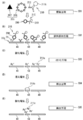
- FIG. 9 is a cross-sectional explanatory view taken along line AA of the first working electrode 43 and the second working electrode 44 in FIG. 4B.
- the first working electrode 43 and the second working electrode are utilized by utilizing the biological interaction between the capture substance 91 and the test substance 206 on the first working electrode 43 and the second working electrode 44.
- the labeled complex 215 containing the test substance 206 is immobilized on the surface 44.
- the method 2-2 can be performed by the same processing procedure as the method 2-1, except for the following points.
- Method 2-1 uses a label-binding substance 210 containing silver particles that are silver 211b
- method 2-2 uses a label-binding substance 220 that contains gold particles that are gold 221b.
- the current, voltage or charge when the silver 211b deposited on the surface of the first working electrode 43 is ionized again is measured, and the test substance 206 is measured based on the current, voltage or charge. To detect.
- the current, voltage or charge when the gold 221b is deposited on the surface of the first working electrode 43 is measured, or the current change, voltage change or A point in which a change in charge is measured, and a test substance 206 is detected based on a current, voltage or charge upon deposition of gold 211b, a change in current accompanying the deposition of gold 211b, a change in voltage or a change in charge.
- the user mixes the sample 205 containing the test substance 206 and the label binding substance 220, and uses the label binding substance 220 for the test substance 206.
- Label In the figure, reference numeral 207 denotes a contaminant that may be contained in the sample 205.
- the user removes the sample containing the labeled complex 225 from the first working electrode 43, the second working electrode 44, the counter electrode 51 (not shown) and the drawing.
- the reference electrode 61 is not added to the electrode substrate 30e so as to cover the exposed portion.
- the test substance 206 of the labeled complex 225 contained in the sample is a capture substance 91 on the surface of each of the first working electrode 43 and the second working electrode 44 formed on the substrate body 31 of the electrode substrate 30e. Captured by Thereby, the labeled complex 225 containing the test substance 206 and the gold 221b is immobilized on the surfaces of the first working electrode 43 and the second working electrode 44, respectively.
- the order of contact between the sample 205, the label binding substance 220, and the capture substance 91 is not particularly limited.
- capture of the test substance 206 in the labeled complex 225 by the capture substance 91 can be performed under the same conditions as the capture of the test substance 206 in the sample addition process S32 in Method 2-1.
- the label complex 225 is immobilized on the surface of each of the first working electrode 43 and the second working electrode 44 by biological interaction between the test substance 206 and the capture substance 91. Can be used.
- the exposed portions of the first working electrode 43, the second working electrode 44, the counter electrode 51 (not shown), and the reference electrode 61 (not shown) are preferably washed with a washing liquid.
- the cleaning liquid used for the cleaning is the same as the cleaning liquid used in the methods 1-1, 1-2 and 2-1.
- the user applies an oxidation potential to both the first working electrode 43 and the second working electrode 44.
- the oxidation potential and the application time of the oxidation potential are the same potentials as the oxidation potential in the method 1-1, 1-2 and the method 2-1, and a potential at which metal ions are generated.
- the gold 221b in the labeling complex 225 is oxidized by both the first working electrode 43 and the second working electrode 44, and the first working electrode 43 and the second working electrode.
- Gold ions 221a can be generated in the vicinity of both.
- the application of the oxidation potential is performed in the presence of an electrolytic solution.
- the electrolytic solution used in the ionization step S43 is the same as the electrolytic solution used in the methods 1-1, 1-2, and 2-1.
- the reduction potential is applied only to the first working electrode 43 without applying the reduction potential to the second working electrode 44.
- a predetermined reduction potential based on the reference electrode 61 is applied only to the first working electrode 43 by the power source 14 of the detection apparatus 10.
- the electrical measuring device 13 measures the current, voltage or charge when the gold 221b is deposited on the surface of the first working electrode 43, or the deposition of the gold 221b on the first working electrode 43. Measure the current change, voltage change or charge change due to.
- test substance 206 is detected based on the current, voltage or charge during the deposition of the gold 221b on the first working electrode, or the change in the current, the change in the voltage or the change in the charge accompanying the deposition of the gold 221b.
- the reduction potential and application time in the detection step S44 are the same as the reduction potential and application time in Method 1-2.
- the reduction potential is applied to the portion having an area smaller than the portion of the portion to which the oxidation potential is applied in order to generate the gold ions 221a in the ionization step S23, thereby depositing the gold 221b.
- current, voltage or charge is measured. Therefore, as shown in FIG. 9D, gold 221b generated from the gold ions 221a generated in the ionization process can be accumulated and deposited by the first working electrode 43.
- the reduction potential is applied in the presence of an electrolytic solution.
- the electrolytic solution used in the detection step S44 is the same as the electrolytic solution used in the methods 1-1, 1-2, and 2-1.
- the current, voltage and charge during the deposition of the gold 221b in the detection step S24 and the current change, voltage change and charge change accompanying the deposition of the gold 221b are the currents in the methods 1-1, 1-2 and 2-1. It can be measured by the same method as the voltage or charge measurement method.
- Method 2-2 quantification of the test substance, semi-quantification of the test substance, and qualitative determination of the presence or absence of the test substance can be performed in the same manner as in Method 2-1.
- Test substance detection kit A test substance detection kit according to the present embodiment includes the electrode substrate described above and a reagent containing metal particles.
- the test substance detection kit according to the present embodiment includes, as shown in FIG. 10, for example, an electrode substrate 30, a reagent bottle 101 containing a metal particle suspension containing metal particles, and a reduction potential or oxidation. It can be provided as a kit 100 including a reagent bottle 102 containing an electrolytic solution used for applying a potential and a reagent bottle 103 containing a cleaning solution for cleaning each electrode.
- the electrode substrate 30 and the reagent bottles 101, 102, and 103 may be provided separately or in combination of two or more.
- Examples of the electrode substrate 30 include, but are not limited to, electrode substrates 30a, 30b, 30c, and 30d.
- the solvent used in the metal particle suspension may be any solvent that can stably hold the metal particles.
- the solvent used for the metal particle suspension include water; buffer solutions such as PBS and TBS containing biomolecules such as bovine serum albumin; aqueous solutions prepared by adjusting salts such as sodium chloride and potassium chloride to a low concentration
- the content of the metal particles in the metal particle suspension can be appropriately determined according to the use of the test substance detection kit.
- the electrolytic solution and the cleaning solution are the same as the electrolytic solution and the cleaning solution used in the methods 1-1, 1-2, 2-1 and 2-2.
- Example 1 Silver ion detection method (1) Production of electrode substrate A carbon paste is applied to the surface of a substrate body 31 made of glass epoxy so as to have a pattern shown in FIG. Thus, the first working electrode 41, the second working electrode 42, the counter electrode 51, the reference electrode main body 61a, and the electrode leads 71, 72, 73, 74 were formed. Next, silver / silver chloride was applied to the tip of the reference electrode main body 61a to obtain the reference electrode 61. The first working electrode 41, the second working electrode 42, the counter electrode 51, and the reference electrode 61 are exposed and the electrode is maintained in order to maintain the contact of the sample with each electrode and suppress the leakage of the sample to each electrode lead. A resist insulating film (see 80 in FIG. 3A) was disposed so as to cover a part of each of the leads 71, 72, 73, 74, and an electrode substrate 30a was obtained.
- a resist insulating film (see 80 in FIG. 3A) was disposed so as to cover a part of each of the leads
- the area of the first working electrode 41 [A1 in FIG. 3A] was set to 0.3 mm 2 .
- the area of the second working electrode 42 (A2 in FIG. 3A) was set to 2.7 mm 2 . Thereby, [area A1 of the first working electrode] / [area of all working electrodes (A1 + A2)] was set to 1/10.
- the distance between the first working electrode 41 and the second working electrode 42 was set to 50 ⁇ m.
- Example 2 (2) Precipitation of silver
- the electrode substrate 30a obtained in Example 1 (1) was connected to a potentiostat [product name: 832B, manufactured by BAS Co., Ltd.].
- 30 ⁇ L of a sample [sodium nitrate aqueous solution (0 pM silver nitrate) or sodium nitrate aqueous solution containing 100 pM silver nitrate] was dropped so that the first working electrode 41, the second working electrode 42, the counter electrode 51, and the reference electrode 61 were covered.
- a potential of ⁇ 1.0 V is applied to both the first working electrode 41 and the second working electrode 42 with respect to the reference electrode 61 for 300 seconds, and the surface of the first working electrode 41 and the second working electrode 42 Silver was precipitated.
- the liquid on the surfaces of the first working electrode 41, the second working electrode 42, the counter electrode 51, and the reference electrode 61 was removed. Thereafter, the first working electrode 41, the second working electrode 42, the counter electrode 51, and the reference electrode 61 were washed with purified water, and then air-dried.
- Example 3 Measurement of silver ions
- the electrode substrate 30a on which silver was deposited in Example 1 (2) was connected to a potentiostat. Next, 30 ⁇ L of 0.05 M sodium chloride aqueous solution was dropped so that the first working electrode 41, the second working electrode 42, the counter electrode 51, and the reference electrode 61 were covered. After the completion of the dropping, a potential of 2.1 V was applied to both the first working electrode 41 and the second working electrode 42 based on the reference electrode 61 for 30 seconds. Thereafter, a potential of ⁇ 1.0 V based on the reference electrode 61 was applied only to the first working electrode 41 for 300 seconds. Thereafter, a potential was swept between ⁇ 0.4 V and 0.4 V with respect to the first working electrode 41 by differential pulse voltammetry, and the current flowing between the first working electrode 41 and the counter electrode 51 was measured.
- FIG. 11 shows the result of detecting the current caused by silver ions contained in the sample in Example 1.
- the white bar indicates the current when a sodium nitrate aqueous solution (0 pM silver nitrate) is used as a sample
- the hatched bar indicates the current when a sodium nitrate aqueous solution containing 100 pM silver nitrate is used as a sample.
- the silver ion detection method of Example 1 is performed from the current when a sodium nitrate aqueous solution (0 pM silver nitrate) is used as a sample and the current when a sodium nitrate aqueous solution containing 100 pM silver nitrate is used as a sample.
- the S / N ratio was determined. As a result, the S / N ratio was 208.
- Example 1 Silver Ion Detection Method
- the electrode substrate 30a on which silver was deposited in Example 1 (2) was connected to a potentiostat. Next, 30 ⁇ L of 0.05 M sodium chloride aqueous solution was dropped so that the first working electrode 41, the second working electrode 42, the counter electrode 51, and the reference electrode 61 were covered. After the completion of the dropping, a potential of 2.1 V was applied to both the first working electrode 41 and the second working electrode 42 based on the reference electrode 61 for 30 seconds. Thereafter, a potential of ⁇ 1.0 V was applied to both the first working electrode 41 and the second working electrode 42 based on the reference electrode 61 for 300 seconds.
- FIG. 11 shows the result of detecting the current caused by the silver ions contained in the sample in Comparative Example 1.
- the current detected by the detection method of the test substance of Comparative Example 1 is the current flowing between the first working electrode 41 and the counter electrode 51 and between the second working electrode 42 and the counter electrode 51. This is the total current that flows.
- the white bar indicates the current when a sodium nitrate aqueous solution (0 pM silver nitrate) is used as a sample
- the hatched bar indicates the current when a sodium nitrate aqueous solution containing 100 pM silver nitrate is used as a sample.
- the silver ion detection method of Comparative Example 1 is performed from the current when a sodium nitrate aqueous solution (0 pM silver nitrate) is used as a sample and the current when a sodium nitrate aqueous solution containing 100 pM silver nitrate is used as a sample.
- the S / N ratio was determined. As a result, the S / N ratio was 21.
- the same electrode substrate as in Example 1 was used.
- silver deposition and ionization were performed on both the first working electrode and the second working electrode. Therefore, the silver ion detection method of this comparative example is a conventional method in which silver is deposited and ionized by only one working electrode having a total area of the area of the first working electrode and the area of the second working electrode. It can be considered equivalent. From the results of Example 1 and Comparative Example 1, it was found that according to the method of Example 1, a signal equivalent to that of the conventional method can be secured and noise can be reduced as compared with the conventional method.
- Example 2 Silver Ion Detection Method
- the electrode substrate 30a on which silver was deposited in Example 1 (2) was connected to a potentiostat. Next, 30 ⁇ L of 0.05 M sodium chloride aqueous solution was dropped so that the first working electrode 41, the second working electrode 42, the counter electrode 51, and the reference electrode 61 were covered. After the dropping, a potential of 2.1 V was applied to only the first working electrode for 30 seconds based on the reference electrode 61. Thereafter, a potential of ⁇ 1.0 V based on the reference electrode 61 was applied only to the first working electrode 41 for 300 seconds. Thereafter, a potential was swept between ⁇ 0.4 V and 0.4 V with respect to the first working electrode 41 by differential pulse voltammetry, and the current flowing between the first working electrode 41 and the counter electrode 51 was measured.
- FIG. 11 shows the result of detecting the current caused by the silver ions contained in the sample in Comparative Example 2.
- the white bar indicates the current when a sodium nitrate aqueous solution (0 pM silver nitrate) is used as a sample
- the hatched bar indicates the current when a sodium nitrate aqueous solution containing 100 pM silver nitrate is used as a sample.
- the silver ion detection method of Comparative Example 2 is performed from the current when a sodium nitrate aqueous solution (0 pM silver nitrate) is used as a sample and the current when a sodium nitrate aqueous solution containing 100 pM silver nitrate is used as a sample.
- the S / N ratio was determined. As a result, the S / N ratio was 37.
- Example 1 the same electrode substrate as in Example 1 was used. However, in this comparative example, silver deposition and ionization were performed using only the first working electrode. Therefore, the silver ion detection method of this comparative example can be considered to be equivalent to the conventional method of depositing and ionizing silver with only one working electrode having the same area as the first working electrode. From the results of Example 1 and Comparative Example 2, it was found that according to the method of Example 1, noise was suppressed to the same level as that of Comparative Example 2 and a higher signal than that of Comparative Example 2 was obtained.
- Example 2 Detection method of test substance (1) Production of electrode substrate main body
- Example 1 (1) instead of applying a carbon paste to the surface of the substrate main body 31 so as to have the pattern shown in FIG.
- the same operation as in Example 1 (1) was performed except that the carbon paste was applied to the surface of the substrate body 31 so as to have the pattern shown in FIG.
- An electrode substrate body having the second working electrode 44, the counter electrode 51, and the reference electrode 61 was obtained.
- the area of the first working electrode 43 [A1 in FIG. 4B] was set to 0.3 mm 2 .
- the area of the second working electrode 44 [A2 in FIG. 4B] was set to 2.7 mm 2 .
- [area A1 of the first working electrode] / [area of all working electrodes (A1 + A2)] was set to 1/10.
- the distance between the first working electrode 43 and the second working electrode 44 was set to 50 ⁇ m.
- Anti-HBs antigen secondary antibody solution [manufactured by Sysmex Corporation] was added to sodium phosphate buffer (pH 7) so that the concentration of anti-HBs antigen secondary antibody was 100 ⁇ g / mL. A secondary antibody solution was obtained.
- the pH of the silver nanoparticle solution (Sigma-Aldrich, silver nanoparticle diameter: 60 nm, silver nanoparticle concentration: 0.02 mg / mL) was adjusted to 6.2 using 1 M hydrochloric acid.
- a 10% (w / v) polyoxyethylene (20) sorbitan monolaurate (Tween 20 (registered trademark)) solution was added.
- 100 ⁇ L of the secondary antibody solution was added and allowed to stand at room temperature for 20 minutes.
- BSA / TBS-T solution 400 ⁇ L of 1% (w / w) BSA-containing TBS-T solution (hereinafter also referred to as “BSA / TBS-T solution”) was added to the obtained mixed solution. Thereafter, the obtained mixed solution was subjected to centrifugation at 6500 ⁇ g for 20 minutes at 4 ° C., and the supernatant was removed. To the obtained residue, 1 mL of 1% BSA / TBS-T solution was added. The obtained mixed solution was subjected to centrifugation at 6500 ⁇ g for 20 minutes at 4 ° C., and the supernatant was removed. To the obtained residue, 1 mL of 1% BSA / TBS-T solution was added.
- test substance The fetal bovine fetus so that the test substance HBs antigen [manufactured by Sysmex Corporation, trade name: HISCL HBsAg calibrator, 2500 IU / mL] is 12.5 IU / mL. It was added to serum (hereinafter also referred to as “FBS”) to obtain HBS antigen-containing FBS.
- FBS concentration of HBs antigen: 0 IU / mL
- HBS antigen-containing FBS as a sample and the labeled complex solution obtained in Example 2 (2) were used as [sample] / [labeled complex].
- Solution] volume ratio was 3/1.
- Electrochemical measurement The electrode substrate 30b on which the test substance was immobilized in Example 2 (5) was connected to a potentiostat. Next, 30 ⁇ L of 0.05 M hydrochloric acid aqueous solution was dropped so that the first working electrode 43, the second working electrode 44, the counter electrode 51, and the reference electrode 61 were covered. After the completion of dropping, a potential of 2.1 V was applied to both the first working electrode 43 and the second working electrode 44 based on the reference electrode 61 for 15 seconds. Thereafter, a potential of ⁇ 1.0 V with respect to the reference electrode 61 was applied to only the first working electrode 43 for 8 minutes. Thereafter, a potential was swept between ⁇ 0.4 V and 0.4 V with respect to the first working electrode 43 by a differential pulse voltammetry method, and a current flowing between the first working electrode 43 and the counter electrode 51 was measured.
- FIG. 12 shows the result of detecting the current caused by the silver nanoparticles in the labeled complex bound to the test substance contained in the sample in Example 2.
- the white bar indicates the current when FBS (HBs antigen concentration: 0 IU / mL) was used as the sample
- the hatched bar indicates the current when FBS containing 12.5 IU / mL HBs antigen was used as the sample. Indicates.
- Example 3 (Comparative example 3) Detection method of test substance
- the electrode substrate 30b on which the test substance was immobilized in Example 2 (5) was connected to a potentiostat.
- 30 ⁇ L of 0.05 M hydrochloric acid was dropped so that the first working electrode 43, the second working electrode 44, the counter electrode 51, and the reference electrode 61 were covered.
- a potential of 2.1 V was applied to both the first working electrode 43 and the second working electrode 44 based on the reference electrode 61 for 15 seconds.
- a potential of ⁇ 1.0 V was applied to both the first working electrode 43 and the second working electrode 44 based on the reference electrode 61 for 8 minutes.
- the first working electrode 43 and the second working electrode 44 are swept between ⁇ 0.4 V and 0.4 V by the differential pulse voltammetry method, and flow between the first working electrode 43 and the counter electrode 51.
- the current and the current flowing between the second working electrode 44 and the counter electrode 51 were measured.
- FIG. 12 shows the result of detecting the current caused by the silver nanoparticles in the labeled complex bound to the test substance contained in the sample in Comparative Example 3.
- the current detected by the test substance detection method of Comparative Example 3 is the current flowing between the first working electrode 43 and the counter electrode 51 and between the second working electrode 44 and the counter electrode 51. This is the total current that flows.
- the white bar indicates the current when FBS (HBs antigen concentration: 0 IU / mL) was used as the sample, and the hatched bar indicates the current when FBS containing 12.5 IU / mL HBs antigen was used as the sample. Indicates.
- the same electrode substrate as in Example 2 was used.
- silver deposition and ionization were performed on both the first working electrode and the second working electrode. Therefore, the detection method of the test substance of this comparative example is a conventional method in which silver is deposited and ionized by only one working electrode having the total area of the first working electrode and the second working electrode. Can be considered equivalent. From the results of Example 2 and Comparative Example 3, it was found that according to the method of Example 2, a signal equivalent to that of the conventional method can be secured and noise can be reduced as compared with the conventional method.
- Example 4 Detection method of test substance
- the electrode substrate 30b on which the test substance was immobilized in Example 2 (5) was connected to a potentiostat.
- 30 ⁇ L of 0.05 M hydrochloric acid was dropped so that the first working electrode 43, the second working electrode 44, the counter electrode 51, and the reference electrode 61 were covered.
- a potential of 2.1 V was applied to the first working electrode 43 based on the reference electrode 61 for 15 seconds.
- a potential of ⁇ 1.0 V with respect to the reference electrode 61 was applied to the first working electrode 43 for 8 minutes.
- a potential was swept between ⁇ 0.4 V and 0.4 V with respect to the first working electrode 43 by a differential pulse voltammetry method, and a current flowing between the first working electrode 43 and the counter electrode 51 was measured.
- FIG. 12 shows the result of detecting the current caused by the silver nanoparticles in the labeled complex bound to the test substance contained in the sample in Comparative Example 4.
- the white bar indicates the current when FBS (HBs antigen concentration: 0 IU / mL) was used as the sample
- the hatched bar indicates the current when FBS containing 12.5 IU / mL HBs antigen was used as the sample. Indicates.
- Example 2 the same electrode substrate as in Example 2 was used. However, in this comparative example, silver deposition and ionization were performed using only the first working electrode. Therefore, the detection method of the test substance of this comparative example can be considered to be equivalent to the conventional method in which silver is deposited and ionized by only one working electrode having the same area as the first working electrode. From the results of Example 2 and Comparative Example 4, it was found that according to the method of Example 2, noise was suppressed to the same level as that of Comparative Example 4, and a higher signal than that of Comparative Example 4 could be obtained.
- test substance HBs antigen [manufactured by Sysmex Corporation, trade name: HISCL HBsAg calibrator, 2500 IU / mL] as HBs It added to FBS so that the density
- concentration of an antigen might be 0.09, 0.19, 0.78, 3.12, 12.5, or 50 IU / mL, and HBS antigen containing FBS was obtained.
- FBS concentration of HBs antigen: 0 IU / mL
- HBS antigen-containing FBS concentration of HBs antigen: 0.09, 0.19, 0.78, 3.12, 12.5 or 50 IU / mL
- [sample] / [labeled complex solution] (volume ratio) was 3/1.
- FIG. 13 shows the results of examining the relationship between the concentration of the test substance in the sample and the current caused by the silver nanoparticles in the labeled complex bound to the test substance contained in the sample in Example 3.
- white circles show the results of measuring the current caused by the silver nanoparticles in the labeled complex bound to the test substance contained in the sample by the test substance detection method of Example 3.
- Example 5 Detection method of test substance (quantitative measurement)
- the electrode substrate 30b on which the test substance was immobilized in Example 3 (1) was connected to a potentiostat. Next, 30 ⁇ L of 0.05 M hydrochloric acid aqueous solution was dropped so that the first working electrode 43, the second working electrode 44, the counter electrode 51, and the reference electrode 61 were covered. After the completion of dropping, a potential of 2.1 V was applied to both the first working electrode 43 and the second working electrode 44 based on the reference electrode 61 for 15 seconds. Thereafter, a potential of ⁇ 1.0 V was applied to both the first working electrode 43 and the second working electrode 44 based on the reference electrode 61 for 8 minutes.
- the first working electrode 43 and the second working electrode 44 are swept between ⁇ 0.4 V and 0.4 V by the differential pulse voltammetry method, and flow between the first working electrode 43 and the counter electrode 51.
- the current and the current flowing between the second working electrode 44 and the counter electrode 51 were measured.
- Comparative Example 5 the result of examining the relationship between the concentration of the test substance in the sample and the current caused by the silver nanoparticles in the labeled complex bound to the test substance contained in the sample is shown in FIG.
- the current detected by the detection method of the test substance of Comparative Example 5 is the current flowing between the first working electrode 43 and the counter electrode 51 and between the second working electrode 44 and the counter electrode 51. This is the total current that flows.
- black circles show the results of measuring the current caused by silver nanoparticles in the labeled complex bound to the test substance contained in the sample by the test substance detection method of Comparative Example 5.
- the detection limit of each detection method calculated from the current value with respect to HBs antigen concentration: 0 IU / mL + 3SD (standard deviation) is 0.09 IU / mL in Example 3, and 0 in Comparative Example 5. .78 IU / mL. That is, the sensitivity of the detection method of Example 3 was about 8 times higher than the sensitivity of the detection method of Comparative Example 5.
- Example 3 the same electrode substrate as in Example 3 was used. However, in this comparative example, silver deposition and ionization were performed on both the first working electrode and the second working electrode. Therefore, it can be considered equivalent to a conventional method in which silver is deposited and ionized with only one working electrode having the same area as the first working electrode. From the results of Example 3 and Comparative Example 5, according to the method of Example 3, even when a sample containing a low concentration of HBs antigen was used, the detection sensitivity was higher than when the conventional method for detecting a test substance was performed. It turns out that it improves.
- Example 4 Detection method (quantitative measurement) of test substance (1) Immobilization of primary antibody Sodium carbonate buffer so that the concentration of primary antibody of anti-HBs antigen is 100 ⁇ g / mL. The solution was added to the solution (pH 9) to obtain a primary antibody solution. 3 ⁇ L of the obtained primary antibody solution was dropped onto the surfaces of the first working electrode 41 and the second working electrode 42 of the electrode substrate 30a obtained in Example 1 (1). Thereafter, the electrode substrate 30a was allowed to stand at room temperature (25 ° C.) for 2 hours under high humidity conditions. Next, the solutions on the surfaces of the first working electrode 41 and the second working electrode 42 were removed.
- test substance HBs antigen which is a test substance (manufactured by Sysmex Corporation, trade name: HISCL HBsAg calibrator, 2500 IU / mL) has an HBs antigen concentration of 0.09, 0.19, 0.78. It added to FBS so that it might become 3.12, 12.5, or 50 IU / mL, and HBS antigen containing FBS was obtained.
- FBS concentration of HBs antigen: 0 IU / mL
- HBS antigen-containing FBS concentration of HBs antigen: 0.09, 0.19, 0.78, 3.12, 12.5 or 50 IU / mL
- [sample] / [labeled complex solution] (volume ratio) was 3/1.
- Example 4 (2) 4 ⁇ L of the obtained mixed solution was dropped onto the surfaces of the first working electrode 41 and the second working electrode 42 of the electrode substrate 30c obtained in Example 4 (2). Thereafter, the electrode substrate 30c was incubated under high humidity conditions at room temperature for 25 minutes to carry out antigen / antibody reaction. Next, the solutions on the surfaces of the first working electrode 41 and the second working electrode 42 were removed. 4 ⁇ L of phosphate buffered saline was dropped on the surface of each of the first working electrode 41 and the second working electrode 42 and washed by pipetting. After washing, phosphate buffered saline on the surfaces of the first working electrode 41 and the second working electrode 42 was removed. Each of the first working electrode 41 and the second working electrode 42 was washed with 1.5 mL of purified water, and then air-dried. Thus, the test substance was fixed on the surfaces of the first working electrode 41 and the second working electrode 42 of the electrode substrate 30c.
- Electrochemical measurement The electrode substrate 30c on which the test substance was immobilized in Example 4 (3) was connected to a potentiostat. Next, 30 ⁇ L of 0.05 M hydrochloric acid aqueous solution was dropped so that the first working electrode 41, the second working electrode 42, the counter electrode 51, and the reference electrode 61 were covered. After the completion of dropping, a potential of 2.1 V was applied to both the first working electrode 41 and the second working electrode 42 based on the reference electrode 61 for 15 seconds. Thereafter, a potential of ⁇ 1.0 V with respect to the reference electrode 61 was applied to only the first working electrode 41 for 5 minutes. Thereafter, a potential was swept between ⁇ 0.4 V and 0.4 V with respect to the first working electrode 41 by differential pulse voltammetry, and the current flowing between the first working electrode 41 and the counter electrode 51 was measured.
- FIG. 14 shows the results of examining the relationship between the concentration of the test substance in the sample and the current caused by the silver nanoparticles in the labeled complex bound to the test substance contained in the sample in Example 4.
- white circles show the results of measuring the current caused by the silver nanoparticles in the labeled complex bound to the test substance contained in the sample by the test substance detection method of Example 4.
- Example 6 Detection method of test substance (quantitative measurement)
- the electrode substrate 30c on which the test substance was immobilized in Example 4 (3) was connected to a potentiostat. Next, 30 ⁇ L of 0.05 M hydrochloric acid aqueous solution was dropped so that the first working electrode 41, the second working electrode 42, the counter electrode 51, and the reference electrode 61 were covered. After the completion of dropping, a potential of 2.1 V was applied to both the first working electrode 41 and the second working electrode 42 based on the reference electrode 61 for 15 seconds. Thereafter, a potential of ⁇ 1.0 V with respect to the reference electrode 61 was applied to both the first working electrode 41 and the second working electrode 42 for 5 minutes.
- the potential is swept between ⁇ 0.4 V and 0.4 V by the differential pulse voltammetry method, and the first working electrode 41 and the counter electrode 51 are And the current flowing between the second working electrode 42 and the counter electrode 51 were measured.
- FIG. 14 shows the result of examining the relationship between the concentration of the test substance in the sample and the current caused by the silver nanoparticles in the labeled complex bound to the test substance contained in the sample in Comparative Example 6.
- the black circles show the results of measuring the current caused by the silver nanoparticles in the labeled complex bound to the test substance contained in the sample by the test substance detection method of Comparative Example 6.
- the test substance detection method of Example 4 has a low concentration (0.09 to 0), similar to the test substance detection method of Example 3 (see white circles in FIG. 14). .78 IU / mL) even when a sample containing HBs antigen is used, noise is suppressed, trace currents derived from low concentration HBs antigen can be quantitatively measured, and quantitative detection of low concentration HBs antigen is possible It can be seen that it is. On the other hand, it can be seen that it is difficult to quantitatively measure the low concentration (0.09 to 0.78 IU / mL) of HBs antigen in the detection method of the test substance of Comparative Example 6.
- Example 4 the same electrode substrate as in Example 4 was used. However, in this comparative example, silver deposition and ionization were performed on both the first working electrode and the second working electrode. Therefore, it can be considered equivalent to a conventional method in which silver is deposited and ionized with only one working electrode having the same area as the first working electrode. From the results of Example 4 and Comparative Example 6, according to the method of Example 4, even when a sample containing a low concentration of HBs antigen was used, the detection sensitivity was higher than when the conventional method for detecting a test substance was performed. It turns out that it improves.
- Example 5 Method for detecting a test substance A test substance detection sensitivity using an electrode board having a different area ratio of the first working electrode and the second working electrode from the electrode board used in Examples 1 to 4 Verified.
- Example 1 (1) instead of applying a carbon paste to the surface of the substrate body 31 so as to have the pattern shown in FIG. An electrode having the first working electrode 45, the second working electrode 46, the counter electrode 51, and the reference electrode 61, which is operated in the same manner as in Example 1 (1) except that the carbon paste is applied so that the pattern shown in FIG. A substrate body was obtained.
- the first working electrode 45 is configured integrally with the electrode lead 71.
- the first working electrode 45 is an exposed portion that is not covered with the resist insulating film 80. In this portion, metal deposition, metal ionization, and the like were performed.
- the first working electrode 45 is a portion indicated by A1 in FIG.
- the second working electrode 46 is configured integrally with the electrode lead 72.
- the second working electrode 46 is an exposed portion that is not covered with the resist insulating film 80. In this part, metal ionization and the like were performed.
- the first working electrode 45 and the second working electrode 46 are hatched.
- the area of the first working electrode 45 (see A1 in FIG. 5B) was set to 0.45 mm 2 .
- the area of the second working electrode 46 (see A2 in FIG. 5B) was set to 2.55 mm 2 .
- [Area of first working electrode (A1)] / [Area of all working electrodes (A1 + A2)] was set to 3/20.
- the distance between the first working electrode 45 and the second working electrode 46 was set to 50 ⁇ m.
- Example 2 (2) Immobilization of primary antibody
- the electrode substrate main body obtained in Example 5 (1) instead of using the electrode substrate main body obtained in Example 2 (1), the electrode substrate main body obtained in Example 5 (1) was used. Except for this, the same operation as in Example 2 (2) was performed, and the primary antibody was immobilized on the electrode substrate body obtained in Example 5 (1).
- Example 2 (3) Blocking treatment In Example 2 (3), instead of using the electrode substrate body on which the primary antibody was immobilized in Example 2 (2), the electrode on which the primary antibody was immobilized in Example 5 (2) Except that the substrate body was used, the same operation as in Example 2 (3) was performed to obtain an electrode substrate 30d.
- HBs antigen manufactured by Sysmex Corporation, trade name: HISCL HBsAg calibrator, 2500 IU / mL
- FBS HBs antigen concentration: 0 IU / mL
- HBs antigen-containing FBS HBs antigen concentration: 3.13 IU / mL
- Electrochemical measurement The electrode substrate 30d on which the test substance was immobilized in Example 5 (4) was connected to a potentiostat. Next, 30 ⁇ L of 0.05 M hydrochloric acid aqueous solution was dropped so that the first working electrode 45, the second working electrode 46, the counter electrode 51, and the reference electrode 61 were covered. After completion of dropping, a potential of 2.1 V was applied to both the first working electrode 45 and the second working electrode 46 based on the reference electrode 61 for 30 seconds. Thereafter, a potential of ⁇ 1.0 V with respect to the reference electrode 61 was applied only to the first working electrode 45 for 4 minutes. Thereafter, a potential was swept between ⁇ 0.4 V and 0.4 V with respect to the first working electrode 45 by a differential pulse voltammetry method, and a current flowing between the first working electrode 45 and the counter electrode 51 was measured.
- FIG. 15 shows the result of detecting the current caused by the silver nanoparticles in the labeled complex bound to the test substance contained in the sample in Example 5.
- white bars indicate current when FBS (HBs antigen concentration: 0 IU / mL) was used as a sample
- hatched bars indicate current when FBS containing 3.13 IU / mL HBs antigen was used as a sample. Indicates.
- Example 7 Detection method of test substance
- the electrode substrate 30d on which the test substance was immobilized in Example 5 (4) was connected to a potentiostat.
- 30 ⁇ L of 0.05 M hydrochloric acid aqueous solution was dropped so that the first working electrode 45, the second working electrode 46, the counter electrode 51, and the reference electrode 61 were covered.
- a potential of 2.1 V was applied to both the first working electrode 45 and the second working electrode 46 based on the reference electrode 61 for 30 seconds.
- a potential of ⁇ 1.0 V with respect to the reference electrode 61 was applied to both the first working electrode 45 and the second working electrode 46 for 4 minutes.
- FIG. 15 shows the result of detecting the current caused by the silver nanoparticles in the labeled complex bound to the test substance contained in the sample in Comparative Example 7.
- the current detected by the detection method of the test substance of Comparative Example 7 is the current flowing between the first working electrode 45 and the counter electrode 51 and between the second working electrode 46 and the counter electrode 51. This is the total current that flows.
- the white bar is the current when FBS (HBs antigen concentration: 0 IU / mL) was used as the sample
- the hatched bar is when FBS containing 3.13 IU / mL HBs antigen was used as the sample Current.
- the noise derived from the electrode is lower than that of the test substance detection method of Comparative Example 7, but the signal derived from the HBs antigen is the same as that of Comparative Example 7. It can be seen that the method is similar to the method for detecting a test substance.
- FBS concentration of HBs antigen: 0 IU / mL
- Comparative Example 7 The S / N ratio when the detection method of the test substance was performed was determined. As a result, the S / N ratio was 4.1.
- the same electrode substrate as in Example 5 was used.
- silver deposition and ionization were performed on both the first working electrode and the second working electrode. Therefore, the detection method of the test substance of this comparative example is a conventional method in which silver is deposited and ionized by only one working electrode having the total area of the first working electrode and the second working electrode. Can be considered equivalent. From the results of Example 5 and Comparative Example 7, it was found that according to the method of Example 5, a signal equivalent to that of the conventional method can be secured and noise can be reduced as compared with the conventional method.
- Example 6 Detection method of test substance Instead of setting the distance between the first working electrode 43 and the second working electrode 44 to 50 ⁇ m, the distance between the first working electrode 43 and the second working electrode 44
- the electrode substrate 30e was obtained by performing the same operation as in Example 2 except that the thickness was set to 100 ⁇ m. Using the obtained electrode substrate 30e, the same operation as in Example 2 was performed, and measurement was performed.
- FIG. 16 shows the result of detecting the current caused by the silver nanoparticles in the labeled complex bound to the test substance contained in the sample in Example 6.
- white bars indicate current when FBS (HBs antigen concentration: 0 IU / mL) was used as a sample
- hatched bars indicate current when FBS containing 3.13 IU / mL HBs antigen was used as a sample. Indicates.
- Example 8 The electrode substrate 30e on which the test substance was immobilized in Example 6 was connected to a potentiostat. Next, 30 ⁇ L of 0.05 M hydrochloric acid aqueous solution was dropped so that the first working electrode 43, the second working electrode 44, the counter electrode 51, and the reference electrode 61 were covered. After the completion of dropping, a potential of 2.1 V was applied to both the first working electrode 43 and the second working electrode 44 based on the reference electrode 61 for 30 seconds. Thereafter, a potential of ⁇ 1.0 V with respect to the reference electrode 61 was applied to both the first working electrode 43 and the second working electrode 44 for 4 minutes. Thereafter, the potential is swept between ⁇ 0.4 V and 0.4 V with respect to the first working electrode 43 by the differential pulse voltammetry method, and flows between the first working electrode 43 and the second working electrode 44 and the counter electrode 51. The current was measured.
- FIG. 16 shows the result of detecting the current caused by the silver nanoparticles in the labeled complex bound to the test substance contained in the sample in Comparative Example 8.
- the current detected by the detection method of the test substance of Comparative Example 7 is the current flowing between the first working electrode 43 and the counter electrode 51 and between the second working electrode 44 and the counter electrode 51. This is the total current that flows.
- white bars indicate current when FBS (HBs antigen concentration: 0 IU / mL) was used as a sample, and hatched bars indicate current when FBS containing 3.13 IU / mL HBs antigen was used as a sample. Indicates.
- the same electrode substrate as in Example 6 was used.
- silver deposition and ionization were performed on both the first working electrode and the second working electrode. Therefore, the detection method of the test substance of this comparative example is a conventional method in which silver is deposited and ionized by only one working electrode having the total area of the first working electrode and the second working electrode. Can be considered equivalent. From the results of Example 6 and Comparative Example 8, it was found that according to the method of Example 6, a signal equivalent to that of the conventional method can be secured and noise can be reduced as compared with the conventional method.
- Example 9 The electrode substrate 30e on which the test substance was immobilized in Example 6 was connected to a potentiostat. Next, 30 ⁇ L of 0.05 M hydrochloric acid aqueous solution was dropped so that the first working electrode 43, the second working electrode 44, the counter electrode 51, and the reference electrode 61 were covered. After the completion of dropping, a potential of 2.1 V was applied to only the first working electrode 43 based on the reference electrode 61 for 30 seconds. Thereafter, a potential of ⁇ 1.0 V with respect to the reference electrode 61 was applied only to the first working electrode 43 for 4 minutes. Thereafter, a potential was swept between ⁇ 0.4 V and 0.4 V with respect to the first working electrode 43 by a differential pulse voltammetry method, and a current flowing between the first working electrode 43 and the counter electrode 51 was measured.
- a potential of 2.1 V was applied to only the first working electrode 43 based on the reference electrode 61 for 30 seconds.
- a potential of ⁇ 1.0 V with respect to the reference electrode 61 was applied only to
- FIG. 16 shows the result of detecting the current caused by the silver nanoparticles in the labeled complex bound to the test substance contained in the sample in Comparative Example 9.
- white bars indicate current when FBS (HBs antigen concentration: 0 IU / mL) was used as a sample
- hatched bars indicate current when FBS containing 3.13 IU / mL HBs antigen was used as a sample. Indicates.
- Example 6 the same electrode substrate as in Example 6 was used. However, in this comparative example, silver deposition and ionization were performed using only the first working electrode. Therefore, the detection method of the test substance of this comparative example can be considered to be equivalent to the conventional method in which silver is deposited and ionized by only one working electrode having the same area as the first working electrode. From the results of Example 6 and Comparative Example 9, it was found that according to the method of Example 6, noise was suppressed to the same level as that of Comparative Example 9, and a higher signal than that of Comparative Example 9 could be obtained.
Abstract
Provided is a method for detecting an analyte. In this method, on a working electrode of an electrode substrate including the working electrode and a counter electrode, metal is deposited or a complex comprising the analyte and metal particles is fixed. After an oxidation potential is applied to the working electrode and metal ions are generated, a reduction potential is applied to a portion of the working electrode having a smaller area than the portion to which the oxidation potential was applied; metal is deposited on the surface of the portion to which the reduction potential was applied; current, voltage, or charge resulting from the deposited metal is measured; and metal-ion or analyte detection is carried out.
Description
本発明は、金属イオンの検出方法、被検物質の検出方法、電極基板および検出キットに関する。
The present invention relates to a metal ion detection method, a test substance detection method, an electrode substrate, and a detection kit.
試料中に含まれる金属イオンまたはその他の被検物質を検出する方法として、例えば、電気化学測定法を用いる方法などがある(例えば、特許文献1参照)。
As a method for detecting metal ions or other analytes contained in a sample, for example, there is a method using an electrochemical measurement method (see, for example, Patent Document 1).
特許文献1には、電気化学測定法を用いて銀イオンまたは被検物質を測定する方法が記載されている。特許文献1に記載の銀イオンの測定方法は、以下のように行なわれる。まず、銀イオンを含有する試料に含まれる銀イオンを作用電極上に電気化学的に析出させる。つぎに、析出した銀を電気化学的に酸化させる際の電流を測定することによって銀イオンの有無または濃度を測定する。また、特許文献1に記載の被検物質の測定方法は、以下のように行なわれる。まず、生物学的相互作用を利用して被検物質の量に対応する量の銀微粒子を作用電極の表面近傍に集積させる。つぎに、集積した銀微粒子を電気化学的に酸化し溶出させる。溶出した銀イオンを還元して作用電極表面に析出させる。その後、析出した銀を電気化学的に酸化させる際の電流を測定することによって被検物質の有無または濃度を検出する。
Patent Document 1 describes a method of measuring silver ions or a test substance using an electrochemical measurement method. The silver ion measuring method described in Patent Document 1 is performed as follows. First, silver ions contained in a sample containing silver ions are electrochemically deposited on the working electrode. Next, the presence or concentration of silver ions is measured by measuring the current when electrochemically oxidizing the deposited silver. Moreover, the measuring method of the to-be-tested substance described in patent document 1 is performed as follows. First, using a biological interaction, an amount of silver fine particles corresponding to the amount of the test substance is accumulated near the surface of the working electrode. Next, the accumulated silver fine particles are electrochemically oxidized and eluted. The eluted silver ions are reduced and deposited on the working electrode surface. Thereafter, the presence or concentration of the test substance is detected by measuring the current when electrochemically oxidizing the deposited silver.
本発明は、高い検出感度で金属イオンまたは被検物質を検出することができる、金属イオンの検出方法および被検物質の検出方法、これらの方法に用いるための電極基板ならびに被検物質の検出キットを提供する。
The present invention can detect a metal ion or a test substance with high detection sensitivity, a metal ion detection method and a test substance detection method, an electrode substrate for use in these methods, and a test substance detection kit I will provide a.
本発明者らは、特許文献1に記載の方法では、後述するように、低濃度の銀イオンまたは被検物質を測定した場合、S/N比(シグナルとノイズの比の値)が小さく、シグナルと銀イオンまたは被検物質の濃度との関係において、直線性が悪い場合があることを見出した。また、本発明者らは、金属イオンを生成させるために酸化電位を印加した部分の面積よりも小さい面積を有する部分に還元電位を印加して金属を析出させた。その結果、本発明者らは、例えば、試料における金属イオンまたは被検物質の濃度が低い場合であっても、大きいS/N比が得られることを見出した。加えて、本発明者らは、例えば、試料における金属イオンまたは被検物質の濃度が低い場合であっても、シグナルと金属イオンまたは被検物質の濃度と関係において、優れた直線性が得られることを見出した。本発明は、これらの知見に基づいてなされたものである。
In the method described in Patent Document 1, when measuring a low concentration of silver ions or a test substance, as described later, the S / N ratio (value of the ratio of signal to noise) is small. It was found that the linearity may be poor in the relationship between the signal and the concentration of silver ion or test substance. In addition, the present inventors applied a reduction potential to a portion having an area smaller than that of a portion to which an oxidation potential was applied in order to generate metal ions, thereby depositing metal. As a result, the present inventors have found that, for example, a large S / N ratio can be obtained even when the concentration of the metal ion or the test substance in the sample is low. In addition, the present inventors can obtain excellent linearity in relation to the signal and the concentration of the metal ion or the test substance even when the concentration of the metal ion or the test substance in the sample is low, for example. I found out. The present invention has been made based on these findings.
本発明の1つの側面は、作用電極と対極とを含む電極基板の作用電極の表面に、被検物質と金属粒子とを含む複合体を固定化する固定化工程、
作用電極に酸化電位を印加することにより、作用電極に固定化された複合体中の金属粒子から金属イオンを生成させるイオン化工程、
作用電極における酸化電位を印加した部分の面積よりも小さい面積を有する部分に還元電位を印加することにより、金属イオンから生成する金属を、還元電位を印加した部分の表面に析出させる析出工程、および
析出工程で析出させた金属に起因する電流、電圧または電荷を測定する測定工程、を含む被検物質の検出方法を含む。 One aspect of the present invention is an immobilization step of immobilizing a complex containing a test substance and metal particles on the surface of a working electrode of an electrode substrate including a working electrode and a counter electrode.
An ionization step of generating metal ions from metal particles in the complex immobilized on the working electrode by applying an oxidation potential to the working electrode;
A deposition step of depositing a metal generated from metal ions on the surface of the portion to which the reduction potential is applied by applying a reduction potential to a portion having an area smaller than the area of the portion to which the oxidation potential is applied in the working electrode; and And a measuring step for measuring a current, voltage, or charge caused by the metal deposited in the deposition step.
本発明の他の側面は、第1作用電極と第2作用電極と対極とを含む電極基板の第1作用電極上および第2作用電極の表面に、被検物質と金属粒子とを含む複合体を固定化する固定化工程、
第1作用電極および第2作用電極に酸化電位を印加することにより、第1作用電極および第2作用電極に固定化された複合体中の金属粒子から金属イオンを生成させるイオン化工程、
第2作用電極には還元電位を印加せず、第1作用電極に還元電位を印加することにより、金属イオンから生成する金属を第1作用電極の表面に析出させる析出工程、および
析出工程で析出させる金属に起因する電流、電圧または電荷を測定する測定工程、を含む被検物質の検出方法を含む。 Another aspect of the present invention is a composite comprising a test substance and metal particles on the first working electrode of the electrode substrate including the first working electrode, the second working electrode, and the counter electrode and on the surface of the second working electrode. Immobilization process,
An ionization step of generating metal ions from metal particles in the complex immobilized on the first working electrode and the second working electrode by applying an oxidation potential to the first working electrode and the second working electrode;
A deposition step for depositing metal generated from metal ions on the surface of the first working electrode by applying a reduction potential to the first working electrode without applying a reduction potential to the second working electrode, and depositing in the deposition step And a measuring step of measuring a current, voltage or charge caused by the metal to be detected.
本発明のさらに他の側面は、作用電極と対極とを含む電極基板の作用電極の表面に、金属イオンを含む試料を接触させ、作用電極に還元電位を印加することにより、金属イオンから生成する金属を作用電極の表面に析出させる第1析出工程、
作用電極に酸化電位を印加することにより、第1析出工程で析出させた金属から金属イオンを生成させるイオン化工程、
作用電極において、酸化電位を印加した部分の面積よりも小さい面積を有する部分に還元電位を印加することにより、金属イオンから生成する金属を、還元電位を印加した部分の表面に析出させる第2析出工程、および
析出工程で析出させる金属に起因する電流、電圧または電荷を測定し、電流、電圧または電荷を測定する測定工程、を含む金属イオンの検出方法を含む。 According to still another aspect of the present invention, a sample containing metal ions is brought into contact with the surface of a working electrode of an electrode substrate including a working electrode and a counter electrode, and a reduction potential is applied to the working electrode to generate the metal ions. A first deposition step for depositing metal on the surface of the working electrode;
An ionization step of generating metal ions from the metal deposited in the first deposition step by applying an oxidation potential to the working electrode;
In the working electrode, by applying a reduction potential to a portion having an area smaller than the area of the portion to which the oxidation potential is applied, a second precipitation that deposits a metal generated from the metal ion on the surface of the portion to which the reduction potential is applied. And a measurement step of measuring a current, voltage or charge caused by the metal deposited in the deposition step and measuring the current, voltage or charge.
本発明のさらに他の側面は、第1作用電極と第2作用電極と対極とを含む電極基板の作用電極の表面に、金属イオンを含む試料を接触させ、作用電極に還元電位を印加することにより、金属イオンから生成する金属を第1作用電極および第2作用電極の表面に析出させる第1析出工程、
第1作用電極および第2作用電極に酸化電位を印加することにより、第1析出工程で析出させた金属から金属イオンを生成させるイオン化工程、
第2作用電極には還元電位を印加せず、第1作用電極に還元電位を印加することにより、金属イオンから生成する金属を、第1作用電極の表面に析出させる第2析出工程、および
析出工程で析出させる金属に起因する電流、電圧または電荷を測定し、電流、電圧または電荷を測定する測定工程、を含む金属イオンの検出方法を含む。 Still another aspect of the present invention is to apply a reduction potential to the working electrode by bringing a sample containing metal ions into contact with the surface of the working electrode of the electrode substrate including the first working electrode, the second working electrode, and the counter electrode. A first deposition step of depositing metal generated from metal ions on the surfaces of the first working electrode and the second working electrode,
An ionization step of generating metal ions from the metal deposited in the first deposition step by applying an oxidation potential to the first working electrode and the second working electrode;
A second deposition step of depositing a metal generated from metal ions on the surface of the first working electrode by applying a reducing potential to the first working electrode without applying a reduction potential to the second working electrode; A method of detecting metal ions, comprising: measuring a current, voltage or charge caused by a metal deposited in the process; and measuring a current, voltage or charge.
本発明の別の側面は、作用電極と、対極とを備え、作用電極が、金属イオンを生成させるための部分と、金属イオンの生成後に金属を析出させるための部分とを含み、金属イオンを生成させるための部分よりも金属イオンの生成後に金属を析出させるための部分が小さくなるように構成されている、前述した金属イオンの検出方法または被検物質の検出方法に用いるための電極基板を含む。
Another aspect of the present invention includes a working electrode and a counter electrode, the working electrode including a portion for generating a metal ion and a portion for depositing a metal after the generation of the metal ion. An electrode substrate for use in the above-described metal ion detection method or test substance detection method, wherein a portion for depositing metal after generation of metal ions is smaller than a portion for generation of metal ions. Including.
本発明の別の側面は、作用電極と、対極とを備え、作用電極が、酸化電位の印加と酸化電位の印加後の還元電位の印加とが行なわれる第1作用電極と、酸化電位の印加が行なわれ、かつ酸化電位の印加後還元電位の印加が行なわれない第2作用電極とを含む、前述した被検物質の検出方法または金属イオンの検出方法に用いるための電極基板を含む。
Another aspect of the present invention includes a first working electrode that includes a working electrode and a counter electrode, wherein the working electrode is applied with an oxidation potential and a reduction potential after the application of the oxidation potential, and the application of the oxidation potential. And a second working electrode to which the reduction potential is not applied after the oxidation potential is applied, and an electrode substrate for use in the above-described test substance detection method or metal ion detection method.
本発明の別の側面は、前述した電極基板と、金属粒子を含む試薬とを含む、被検物質の検出キットを含む。
Another aspect of the present invention includes a test substance detection kit including the electrode substrate described above and a reagent containing metal particles.
本発明によれば、高い検出感度で金属イオンまたは被検物質を検出することができる、金属イオンの検出方法および被検物質の検出方法、これらの方法に用いるための電極基板ならびに被検物質の検出キットを提供できる。
According to the present invention, a metal ion detection method and a test substance detection method capable of detecting a metal ion or a test substance with high detection sensitivity, an electrode substrate for use in these methods, and a test substance A detection kit can be provided.
1.用語の定義
本明細書において、「X以上」は、Xの値と、Xよりも大きい値とを含むことを意味する。また、「Y以下」は、Yの値と、Yよりも小さい値とを含むことを意味する。さらに、「X~Y」のように、端点による数値範囲の記載は、各範囲内に含まれるすべての数および有理数ならびに記載されている端点を含む。 1. Definition of Terms In this specification, “X or more” means including a value of X and a value larger than X. “Y or less” means that the value of Y and a value smaller than Y are included. Further, as in “X to Y”, the description of numerical ranges by endpoints includes all numbers and rational numbers included within each range as well as the endpoints being described.
本明細書において、「X以上」は、Xの値と、Xよりも大きい値とを含むことを意味する。また、「Y以下」は、Yの値と、Yよりも小さい値とを含むことを意味する。さらに、「X~Y」のように、端点による数値範囲の記載は、各範囲内に含まれるすべての数および有理数ならびに記載されている端点を含む。 1. Definition of Terms In this specification, “X or more” means including a value of X and a value larger than X. “Y or less” means that the value of Y and a value smaller than Y are included. Further, as in “X to Y”, the description of numerical ranges by endpoints includes all numbers and rational numbers included within each range as well as the endpoints being described.
本明細書において、「被検物質」は、金属イオン以外の物質を意味する。被検物質としては、例えば、核酸、タンパク質、ペプチド、糖鎖、抗原、抗体などが挙げられるが、特に限定されない。
In this specification, “test substance” means a substance other than metal ions. Examples of the test substance include, but are not limited to, nucleic acids, proteins, peptides, sugar chains, antigens, antibodies, and the like.
2.検出装置の構成
まず、金属イオンの検出方法および被検物質の検出方法に用いられる検出装置の一例を添付図面により説明する。図1において、検出装置10は、電極基板30が挿入される基板受入部11と、検出結果を表示するディスプレイ12とを含んでいる。検出装置10は、図2に示されるように、ディスプレイ12と、電気測定装置13と、電源14と、A/D変換部15と、制御部16とを含んでいる。 2. Configuration of Detection Device First, an example of a detection device used in a metal ion detection method and a test substance detection method will be described with reference to the accompanying drawings. In FIG. 1, thedetection device 10 includes a substrate receiving unit 11 into which an electrode substrate 30 is inserted, and a display 12 that displays a detection result. As shown in FIG. 2, the detection device 10 includes a display 12, an electrical measurement device 13, a power source 14, an A / D conversion unit 15, and a control unit 16.
まず、金属イオンの検出方法および被検物質の検出方法に用いられる検出装置の一例を添付図面により説明する。図1において、検出装置10は、電極基板30が挿入される基板受入部11と、検出結果を表示するディスプレイ12とを含んでいる。検出装置10は、図2に示されるように、ディスプレイ12と、電気測定装置13と、電源14と、A/D変換部15と、制御部16とを含んでいる。 2. Configuration of Detection Device First, an example of a detection device used in a metal ion detection method and a test substance detection method will be described with reference to the accompanying drawings. In FIG. 1, the
電気測定装置13は、析出させる金属に起因する電流、電圧または電荷を測定する。電源14は、電極基板30に設けられた電極に対して所定の電位を印加する。A/D変換部15は、電気測定装置13によって測定された電流値、電圧値または電荷の値をデジタル変換する。制御部16は、CPU(Central Processing Unit)、ROM(Read Only Memory)、RAM(Random Access
Memory)などを含んでいる。制御部16は、ディスプレイ12、電気測定装置13および電源14の動作を制御する。また、制御部16は、後述のように、電極基板の作用電極への酸化電位および還元電位の印加を制御する。さらに、制御部16は、A/D変換部15でデジタル変換された電流値から、予め作成された電流値、電圧値または電荷の値と、金属の量との関係を示す検量線に基づき、金属の量を概算し、金属イオンの量または被検物質の量を算出することができる。ディスプレイ12は、制御部16で算出された金属イオンの量または被検物質の量などの情報を表示する。 Theelectrical measuring device 13 measures current, voltage, or electric charge caused by the deposited metal. The power supply 14 applies a predetermined potential to the electrodes provided on the electrode substrate 30. The A / D converter 15 digitally converts the current value, voltage value, or charge value measured by the electrical measurement device 13. The control unit 16 includes a CPU (Central Processing Unit), a ROM (Read Only Memory), and a RAM (Random Access).
Memory) and the like. Thecontrol unit 16 controls operations of the display 12, the electrical measurement device 13, and the power supply 14. Moreover, the control part 16 controls application of the oxidation potential and the reduction potential to the working electrode of the electrode substrate, as will be described later. Further, the control unit 16 is based on a calibration curve indicating a relationship between a current value, a voltage value or a charge value created in advance from the current value digitally converted by the A / D conversion unit 15 and the amount of metal, By estimating the amount of metal, the amount of metal ions or the amount of a test substance can be calculated. The display 12 displays information such as the amount of metal ions or the amount of test substance calculated by the control unit 16.
Memory)などを含んでいる。制御部16は、ディスプレイ12、電気測定装置13および電源14の動作を制御する。また、制御部16は、後述のように、電極基板の作用電極への酸化電位および還元電位の印加を制御する。さらに、制御部16は、A/D変換部15でデジタル変換された電流値から、予め作成された電流値、電圧値または電荷の値と、金属の量との関係を示す検量線に基づき、金属の量を概算し、金属イオンの量または被検物質の量を算出することができる。ディスプレイ12は、制御部16で算出された金属イオンの量または被検物質の量などの情報を表示する。 The
Memory) and the like. The
3.電極基板の構成
本実施形態に係る電極基板は、作用電極と、対極とを備えている。作用電極は、金属イオンを生成させるための部分(以下、「イオン生成部」ともいう)と、金属イオンの生成後に金属を析出させるための部分(以下、「金属析出部」ともいう)とを含む。また、作用電極では、金属析出部の面積が、イオン生成部の面積よりも小さくなるように構成されている。そのため、作用電極全体で金属イオン生成および金属イオン生成後の金属析出を行なう場合に比べて、作用電極の一部分のみで電流、電圧または電荷の測定を行なうので、ノイズが低減される。また、本実施形態に係る電極基板によれば、大きい面積の部分(イオン生成部)で金属イオンを生成させた後、当該金属イオンを小さい面積の部分(金属析出部)に集積させて金属を析出させることができる。そのため、作用電極全体で金属イオン生成および金属イオン生成後の金属析出を行なう場合と同等のシグナルを得ることができる。したがって、S/N比が向上する。 3. Configuration of Electrode Substrate The electrode substrate according to the present embodiment includes a working electrode and a counter electrode. The working electrode includes a part for generating metal ions (hereinafter also referred to as “ion generation part”) and a part for precipitation of metal after generation of metal ions (hereinafter also referred to as “metal precipitation part”). Including. In addition, the working electrode is configured such that the area of the metal deposition part is smaller than the area of the ion generation part. Therefore, compared to the case where metal ions are generated on the entire working electrode and metal deposition after the metal ions are generated, the current, voltage or charge is measured only on a part of the working electrode, so that noise is reduced. In addition, according to the electrode substrate according to the present embodiment, after generating metal ions in a large area portion (ion generation portion), the metal ions are accumulated in a small area portion (metal precipitation portion) to obtain metal. It can be deposited. Therefore, it is possible to obtain a signal equivalent to the case where metal ion generation and metal deposition after metal ion generation are performed on the entire working electrode. Therefore, the S / N ratio is improved.
本実施形態に係る電極基板は、作用電極と、対極とを備えている。作用電極は、金属イオンを生成させるための部分(以下、「イオン生成部」ともいう)と、金属イオンの生成後に金属を析出させるための部分(以下、「金属析出部」ともいう)とを含む。また、作用電極では、金属析出部の面積が、イオン生成部の面積よりも小さくなるように構成されている。そのため、作用電極全体で金属イオン生成および金属イオン生成後の金属析出を行なう場合に比べて、作用電極の一部分のみで電流、電圧または電荷の測定を行なうので、ノイズが低減される。また、本実施形態に係る電極基板によれば、大きい面積の部分(イオン生成部)で金属イオンを生成させた後、当該金属イオンを小さい面積の部分(金属析出部)に集積させて金属を析出させることができる。そのため、作用電極全体で金属イオン生成および金属イオン生成後の金属析出を行なう場合と同等のシグナルを得ることができる。したがって、S/N比が向上する。 3. Configuration of Electrode Substrate The electrode substrate according to the present embodiment includes a working electrode and a counter electrode. The working electrode includes a part for generating metal ions (hereinafter also referred to as “ion generation part”) and a part for precipitation of metal after generation of metal ions (hereinafter also referred to as “metal precipitation part”). Including. In addition, the working electrode is configured such that the area of the metal deposition part is smaller than the area of the ion generation part. Therefore, compared to the case where metal ions are generated on the entire working electrode and metal deposition after the metal ions are generated, the current, voltage or charge is measured only on a part of the working electrode, so that noise is reduced. In addition, according to the electrode substrate according to the present embodiment, after generating metal ions in a large area portion (ion generation portion), the metal ions are accumulated in a small area portion (metal precipitation portion) to obtain metal. It can be deposited. Therefore, it is possible to obtain a signal equivalent to the case where metal ion generation and metal deposition after metal ion generation are performed on the entire working electrode. Therefore, the S / N ratio is improved.
作用電極において、酸化還元電位印加部と、酸化電位印加部とを設けてもよい。酸化還元電位印加部には、金属イオン生成のために酸化電位が印加され、かつ金属イオン生成後の金属析出のために還元電位が印加される。酸化電位印加部には、金属イオンを生成させるために酸化電位が印加されるが、金属イオン生成後は還元電位が印加されない。酸化還元電位印加部と、酸化電位印加部とは、互いに電気的に絶縁されている。この場合、イオン生成部は、酸化還元電位印加部と酸化電位印加部とから構成される。また、金属析出部は、酸化還元電位印加部からなる。
In the working electrode, an oxidation-reduction potential application unit and an oxidation potential application unit may be provided. An oxidation potential is applied to the oxidation-reduction potential application unit to generate metal ions, and a reduction potential is applied to deposit metal after the generation of metal ions. An oxidation potential is applied to the oxidation potential application unit to generate metal ions, but no reduction potential is applied after the metal ions are generated. The oxidation-reduction potential application unit and the oxidation potential application unit are electrically insulated from each other. In this case, the ion generation unit includes an oxidation-reduction potential application unit and an oxidation potential application unit. Further, the metal deposition part is composed of an oxidation-reduction potential application part.
以下、電極基板の一例を添付図面により説明する。図3(A)において、電極基板30aは、基板本体31を備えている。
Hereinafter, an example of the electrode substrate will be described with reference to the accompanying drawings. In FIG. 3A, the electrode substrate 30 a includes a substrate body 31.
基板本体31の表面には、第1作用電極41と、第2作用電極42と、対極51と、参照電極61と、電極リード71,72,73,74とが形成されている。第1作用電極41、第2作用電極42、対極51および参照電極61が露出し、かつ電極リード71,72,73,74の一部が覆われるように、レジスト絶縁膜80が配置されている。これにより、各電極への試料の接触を維持し、かつ各電極リードへの試料の漏出が抑制されている。図3に示される実施形態において、第1作用電極41は、電極リード71と一体的に構成されている。図3(B)においては、第1作用電極41は、レジスト絶縁膜80に覆われていない露出した部分である。この部分において、金属の析出、金属のイオン化などが行なわれる。図3(B)では、第1作用電極41は、A1で示される2つの部分からなる。また、第2作用電極42は、電極リード72と一体的に構成されている。図3(B)においては、第2作用電極42は、レジスト絶縁膜80に覆われていない露出した部分である。この部分において、金属のイオン化などが行なわれる。図3(B)においては、第1作用電極41および第2作用電極42にハッチを付している。
A first working electrode 41, a second working electrode 42, a counter electrode 51, a reference electrode 61, and electrode leads 71, 72, 73, 74 are formed on the surface of the substrate body 31. The resist insulating film 80 is disposed so that the first working electrode 41, the second working electrode 42, the counter electrode 51, and the reference electrode 61 are exposed and a part of the electrode leads 71, 72, 73, 74 is covered. . Thereby, the contact of the sample to each electrode is maintained, and the leakage of the sample to each electrode lead is suppressed. In the embodiment shown in FIG. 3, the first working electrode 41 is configured integrally with the electrode lead 71. In FIG. 3B, the first working electrode 41 is an exposed portion that is not covered with the resist insulating film 80. In this portion, metal deposition, metal ionization, and the like are performed. In FIG. 3 (B), the 1st working electrode 41 consists of two parts shown by A1. The second working electrode 42 is configured integrally with the electrode lead 72. In FIG. 3B, the second working electrode 42 is an exposed portion that is not covered with the resist insulating film 80. In this part, metal ionization and the like are performed. In FIG. 3B, the first working electrode 41 and the second working electrode 42 are hatched.
第1作用電極41および第2作用電極42は、基板本体31の一側部〔図3(A)の上側〕に配置されている。電極リード71は、第1作用電極41から基板本体31の他側部〔図3(A)の下側〕に向けて延びている。電極リード72は、第2作用電極42から基板本体31の他側部〔図3の下側〕に向けて延びている。対極51は、基板本体31上において、第1作用電極41および第2作用電極42よりも外側〔図3(A)において、第1作用電極41および第2作用電極42の上側〕に配置されている。電極リード73は、対極51から、第1作用電極41、第2作用電極42および参照電極61を迂回して、基板本体31の他側部〔図3の下側〕に向けて延びている。参照電極61は、第1作用電極41および第2作用電極42を挟んで、対極51と対向する位置に配置されている。電極リード74は、参照電極61から基板本体31の他側部〔図3の下側〕に向けて延びている。電極リード71,72,73,74は、基板本体31の他側部(図3の下側)において互いに並列するように配置されている。
The first working electrode 41 and the second working electrode 42 are arranged on one side of the substrate body 31 (upper side in FIG. 3A). The electrode lead 71 extends from the first working electrode 41 toward the other side of the substrate body 31 (the lower side in FIG. 3A). The electrode lead 72 extends from the second working electrode 42 toward the other side of the substrate body 31 (the lower side in FIG. 3). The counter electrode 51 is disposed on the substrate body 31 outside the first working electrode 41 and the second working electrode 42 (on the upper side of the first working electrode 41 and the second working electrode 42 in FIG. 3A). Yes. The electrode lead 73 extends from the counter electrode 51 toward the other side of the substrate body 31 (the lower side in FIG. 3), bypassing the first working electrode 41, the second working electrode 42 and the reference electrode 61. The reference electrode 61 is disposed at a position facing the counter electrode 51 with the first working electrode 41 and the second working electrode 42 interposed therebetween. The electrode lead 74 extends from the reference electrode 61 toward the other side of the substrate body 31 (the lower side in FIG. 3). The electrode leads 71, 72, 73, 74 are arranged in parallel with each other on the other side (lower side in FIG. 3) of the substrate body 31.
図3に示される電極基板30aでは、第1作用電極41および第2作用電極42の両方がイオン生成部であり、第1作用電極41が金属析出部である。第1作用電極41は、酸化還元電位印加部である。第1作用電極41には、酸化電位の印加および当該酸化電位の印加後の還元電位の印加が行なわれる。第2作用電極42は、酸化電位印加部である。第2作用電極42には、酸化電位の印加が行なわれるが、当該酸化電位の印加後の還元電位の印加は行なわれない。第1作用電極41と第2作用電極42との間は、図3(B)に示されるように、距離ΔGの隙間によって互いに電気的に絶縁されている。
In the electrode substrate 30a shown in FIG. 3, both the first working electrode 41 and the second working electrode 42 are ion generating parts, and the first working electrode 41 is a metal deposition part. The first working electrode 41 is an oxidation-reduction potential application unit. The first working electrode 41 is applied with an oxidation potential and a reduction potential after the oxidation potential is applied. The second working electrode 42 is an oxidation potential application unit. Although the oxidation potential is applied to the second working electrode 42, the reduction potential is not applied after the oxidation potential is applied. As shown in FIG. 3B, the first working electrode 41 and the second working electrode 42 are electrically insulated from each other by a gap of a distance ΔG.
金属イオンまたは被検物質の検出に際して、金属の析出に伴う電流、電圧または電荷を測定する場合、金属を析出させる部分の面積が小さいほど、ノイズが低いことが本発明者らによって見出されている。したがって、第1作用電極41の面積〔図3(B)中、A1参照〕と、全作用電極の面積〔図3(B)中、A1+A2参照〕との比の値〔A1/(A1+A2)〕が小さいほど、S/N比を向上することができる。A1/(A1+A2)は、S/N比を向上させる観点から、通常、好ましくは1/2以下、より好ましくは1/10以下である。一方、A1/(A1+A2)の下限値は、基板本体の表面への電極の形成方法による形成精度の限界、電極基板の用途などに応じて適宜決定することができる。なお、「全作用電極」は、第1作用電極および第2作用電極の両方を含む概念を意味する。
In the detection of metal ions or test substances, the present inventors have found that when measuring the current, voltage or charge associated with metal deposition, the smaller the area of the metal deposited portion, the lower the noise. Yes. Therefore, the value [A1 / (A1 + A2)] of the area of the first working electrode 41 [see A1 in FIG. 3B] and the area of all working electrodes [see A1 + A2 in FIG. 3B]. The smaller the is, the more the S / N ratio can be improved. A1 / (A1 + A2) is usually preferably ½ or less, more preferably 1/10 or less, from the viewpoint of improving the S / N ratio. On the other hand, the lower limit value of A1 / (A1 + A2) can be appropriately determined according to the limit of formation accuracy by the method of forming the electrode on the surface of the substrate body, the use of the electrode substrate, and the like. “All working electrodes” means a concept including both the first working electrode and the second working electrode.
また、本実施形態において、第1作用電極41と第2作用電極42との間の距離ΔGが小さいほど、第1作用電極41への金属イオンの移動時間が短縮される。したがって、金属イオンまたは被検物質の検出に要する操作時間の短縮が期待される。第1作用電極41と第2作用電極42との間の距離ΔGは、金属イオンまたは被検物質の検出に要する操作時間の短縮する観点から、通常、好ましくは100μm以下、より好ましくは50μm以下である。一方、第1作用電極41と第2作用電極42との間の距離ΔGの下限値は、基板本体の表面への電極の形成方法による限界、電極基板の用途などに応じて適宜決定することができる。
In this embodiment, the movement time of the metal ions to the first working electrode 41 is shortened as the distance ΔG between the first working electrode 41 and the second working electrode 42 is smaller. Therefore, shortening of the operation time required for detection of a metal ion or a test substance is expected. The distance ΔG between the first working electrode 41 and the second working electrode 42 is usually preferably 100 μm or less, more preferably 50 μm or less, from the viewpoint of shortening the operation time required for detection of metal ions or a test substance. is there. On the other hand, the lower limit value of the distance ΔG between the first working electrode 41 and the second working electrode 42 can be appropriately determined according to the limit of the electrode forming method on the surface of the substrate body, the use of the electrode substrate, and the like. it can.
図3に示される電極基板30aにおいて、第2作用電極42は、櫛形形状を有している。第1作用電極41は、図3に示されるように、第2作用電極の櫛歯の隙間部分に挿入されるよう配置されている。これにより、第1作用電極41と第2作用電極42との間で金属イオンを容易に移動させることができる。また、製造も容易である。なお、第1作用電極41および第2作用電極42それぞれの形状は、多角形形状、矩形状、円盤状、楕円状などであってもよい。
In the electrode substrate 30a shown in FIG. 3, the second working electrode 42 has a comb shape. As shown in FIG. 3, the first working electrode 41 is disposed so as to be inserted into a gap portion of the comb teeth of the second working electrode. Thereby, metal ions can be easily moved between the first working electrode 41 and the second working electrode 42. Moreover, manufacture is also easy. Each of the first working electrode 41 and the second working electrode 42 may have a polygonal shape, a rectangular shape, a disk shape, an elliptical shape, or the like.
第2作用電極の櫛歯部分の櫛歯の数は、特に限定されない。図3では、第2作用電極42の櫛歯部分の櫛歯の数は、3本である。図4では、第2作用電極44の櫛歯部分の櫛歯の数は2本である。図5では、第2作用電極46の櫛歯部分の櫛歯の数は4本である。図3(B)、図4(B)および図5(B)それぞれのA1で示される第1作用電極は、第2作用電極の複数本の櫛歯の全ての間隙に挿入されるよう配置されることが好ましい。
The number of comb teeth in the comb tooth portion of the second working electrode is not particularly limited. In FIG. 3, the number of comb teeth in the comb tooth portion of the second working electrode 42 is three. In FIG. 4, the number of comb teeth in the comb tooth portion of the second working electrode 44 is two. In FIG. 5, the number of comb teeth in the comb tooth portion of the second working electrode 46 is four. The first working electrode indicated by A1 in each of FIGS. 3 (B), 4 (B) and 5 (B) is arranged to be inserted into all the gaps of the plurality of comb teeth of the second working electrode. It is preferable.
なお、基板本体31の表面上には、第1作用電極として機能する1個以上の電極を設けることができる。また、基板本体31の表面上には、第2作用電極として機能する1個以上の電極を設けることができる。
Note that one or more electrodes functioning as the first working electrode can be provided on the surface of the substrate body 31. Further, one or more electrodes functioning as the second working electrode can be provided on the surface of the substrate body 31.
第1作用電極41および第2作用電極42は、それぞれ、導電性を有する薄膜から構成されている。導電性を有する薄膜は、主に導電性材料から構成されている。導電性材料としては、例えば、グラファイト、グラシーカーボン、パイロリティックグラファイト、カーボンペースト、カーボンファイバー、カーボンナノチューブ、グラフェンなどの炭素材料;金、白金などの金属材料、スズをドープした酸化インジウム(ITO)、フッ素をドープした酸化スズ(FTO)などの酸化物半導体などが挙げられるが、特に限定されない。なお、第1作用電極41および第2作用電極42は、ガラス、プラスチックなどの非導電性物質からなる非導電性基材の表面に導電性材料からなる導電層が設けられた複合基材などから構成されていてもよい。薄膜の厚さは、電極基板の用途などに応じて適宜決定することが望ましい。
The first working electrode 41 and the second working electrode 42 are each composed of a thin film having conductivity. The conductive thin film is mainly composed of a conductive material. Examples of the conductive material include carbon materials such as graphite, glassy carbon, pyrolytic graphite, carbon paste, carbon fiber, carbon nanotube, and graphene; metal materials such as gold and platinum; indium oxide doped with tin (ITO) And oxide semiconductors such as tin oxide (FTO) doped with fluorine, but are not particularly limited. The first working electrode 41 and the second working electrode 42 are made of a composite base material in which a conductive layer made of a conductive material is provided on the surface of a non-conductive base material made of a non-conductive material such as glass or plastic. It may be configured. The thickness of the thin film is desirably determined as appropriate according to the use of the electrode substrate.
図3において、電極基板が被検物質の検出に用いるための電極基板である場合、第1作用電極41および第2作用電極42の表面には、被検物質に結合する捕捉物質が固定化されていることが好ましい。捕捉物質としては、例えば、核酸、タンパク質、ペプチド、糖鎖、抗体、特異的な認識能を有するナノ構造体などが挙げられるが、特に限定されない。捕捉物質は、被検物質の種類などに応じて適宜決定することが望ましい。被検物質が核酸である場合、捕捉物質として、かかる核酸にハイブリダイズする核酸プローブ、核酸に対する抗体などを用いることができる。被検物質がタンパク質またはペプチドである場合、捕捉物質として、抗体を用いることができる。被検物質が糖鎖である場合、捕捉物質として、かかる糖鎖に対するレクチン、糖鎖に対する抗体などを用いることができる。被検物質が抗原である場合、捕捉物質として、かかる抗原に対する抗体などを用いることができる。
In FIG. 3, when the electrode substrate is an electrode substrate for use in detecting a test substance, a capture substance that binds to the test substance is immobilized on the surfaces of the first working electrode 41 and the second working electrode. It is preferable. Examples of the capture substance include, but are not limited to, nucleic acids, proteins, peptides, sugar chains, antibodies, and nanostructures having specific recognition ability. It is desirable that the capture substance is appropriately determined according to the type of the test substance. When the test substance is a nucleic acid, a nucleic acid probe that hybridizes to the nucleic acid, an antibody against the nucleic acid, or the like can be used as the capture substance. When the test substance is a protein or peptide, an antibody can be used as the capture substance. When the test substance is a sugar chain, a lectin against the sugar chain, an antibody against the sugar chain, or the like can be used as the capture substance. When the test substance is an antigen, an antibody against the antigen can be used as the capture substance.
第1作用電極41および第2作用電極42の表面に固定化される単位面積当たりの捕捉物質の量は、被検物質の種類、捕捉物質の種類などに応じて適宜決定することが望ましい。第1作用電極41および第2作用電極42の表面に固定化される単位面積あたりの捕捉物質の量は、被検物質を捕捉するのに十分な量であればよい。
It is desirable to appropriately determine the amount of the capturing substance per unit area immobilized on the surfaces of the first working electrode 41 and the second working electrode 42 according to the type of the test substance, the type of the capturing substance, and the like. The amount of the capturing substance per unit area immobilized on the surfaces of the first working electrode 41 and the second working electrode 42 may be an amount sufficient to capture the test substance.
本実施形態においては、基板本体31は、矩形状を呈している。しかし、基板本体31の形状は、特に限定されるものではなく、多角形形状、円盤状などであってもよい。
In the present embodiment, the substrate body 31 has a rectangular shape. However, the shape of the substrate body 31 is not particularly limited, and may be a polygonal shape, a disk shape, or the like.
基板本体31を構成する材料としては、例えば、ポリエチレンテレフタレート、ポリイミド、ガラスエポキシなどのプラスチック類;ガラス、金属などの無機材料などが挙げられるが、特に限定されない。基板本体31の厚さは、電極基板の用途などに応じて適宜決定することが望ましい。
Examples of the material constituting the substrate body 31 include, but are not limited to, plastics such as polyethylene terephthalate, polyimide, and glass epoxy; and inorganic materials such as glass and metal. It is desirable that the thickness of the substrate body 31 is appropriately determined according to the use of the electrode substrate.
対極51は、導電性を有する薄膜から構成されている。導電性を有する薄膜は、主に導電性材料から構成されている。対極51に用いられる導電性材料は、第1作用電極41および第2作用電極42に用いられる導電性材料と同様である。対極51を構成する薄膜の厚さは、電極基板の用途などに応じて適宜決定することが望ましい。
The counter electrode 51 is composed of a conductive thin film. The conductive thin film is mainly composed of a conductive material. The conductive material used for the counter electrode 51 is the same as the conductive material used for the first working electrode 41 and the second working electrode 42. The thickness of the thin film constituting the counter electrode 51 is desirably determined as appropriate according to the use of the electrode substrate.
参照電極61は、導電性を有する薄膜からなる。導電性を有する薄膜は、主に導電性材料から構成されている。導電性材料としては、例えば、金、銀、銅、カーボン、白金、パラジウム、クロム、アルミニウム、ニッケルなどの金属;当該金属の少なくとも1つを含む合金;金属の塩化物などの金属ハロゲン化物;これらの混合物などが挙げられるが、特に限定されない。参照電極61は、ガラス、ガラスエポキシ、プラスチックなどの非導電性物質からなる非導電性基材の表面に導電性材料からなる導電層が設けられた複合基材などから構成されていてもよい。かかる参照電極61の具体例としては、例えば、銀-塩化銀電極、水銀と塩化水銀とを用いるカロメル電極などが挙げられるが、特に限定されない。参照電極61を構成する薄膜の厚さは、電極基板の用途などに応じて適宜決定することが望ましい。なお、本実施形態では、基板本体31の表面に参照電極61が設けられている。そのため、本実施形態に係る電極基板30aによれば、大きな電流を測定する場合、電圧降下の影響を抑制し、第1作用電極41および第2作用電極42に印加する電圧を安定化させることができる。しかし、他の実施形態では、基板本体31の表面に参照電極61が設けられていなくてもよい。例えば、対極51に用いられる導電性材料の種類、対極51の厚さなどにもよるが、電圧降下の影響が僅かな小さな電流(例えば、1μA以下)を測定する場合、対極51が参照電極61を兼ねていてもよい。
The reference electrode 61 is made of a conductive thin film. The conductive thin film is mainly composed of a conductive material. Examples of the conductive material include metals such as gold, silver, copper, carbon, platinum, palladium, chromium, aluminum, and nickel; alloys containing at least one of the metals; metal halides such as metal chlorides; There are no particular limitations. The reference electrode 61 may be composed of a composite substrate in which a conductive layer made of a conductive material is provided on the surface of a nonconductive substrate made of a nonconductive material such as glass, glass epoxy, or plastic. Specific examples of the reference electrode 61 include, for example, a silver-silver chloride electrode, and a calomel electrode using mercury and mercury chloride, but are not particularly limited. The thickness of the thin film constituting the reference electrode 61 is desirably determined as appropriate according to the use of the electrode substrate. In the present embodiment, the reference electrode 61 is provided on the surface of the substrate body 31. Therefore, according to the electrode substrate 30a according to the present embodiment, when measuring a large current, it is possible to suppress the influence of the voltage drop and stabilize the voltage applied to the first working electrode 41 and the second working electrode 42. it can. However, in other embodiments, the reference electrode 61 may not be provided on the surface of the substrate body 31. For example, depending on the type of conductive material used for the counter electrode 51 and the thickness of the counter electrode 51, when measuring a small current (for example, 1 μA or less) that is slightly affected by a voltage drop, the counter electrode 51 is used as the reference electrode 61. You may also serve.
本実施形態に係る電極基板は、例えば、以下の工程を含む方法などによって製造することができる。(I)基板本体の表面に、作用電極、対極および任意に参照電極のパターンを形成するように導電性を有する薄膜を形成させる工程、(II)必要により、作用電極の表面に捕捉物質を固定化する工程、(III)必要により、作用電極表面のブロッキング処理を行なう工程。
The electrode substrate according to the present embodiment can be manufactured by, for example, a method including the following steps. (I) A step of forming a conductive thin film on the surface of the substrate body so as to form a pattern of a working electrode, a counter electrode, and optionally a reference electrode. (II) If necessary, a capture substance is fixed on the surface of the working electrode. (III) A step of performing blocking treatment on the working electrode surface, if necessary.
工程(I)において、導電性を有する薄膜の形成は、例えば、スクリーン印刷法、フォトリソグラフィー法などの方法によって行なうことができる。
In step (I), the formation of the conductive thin film can be performed by a method such as a screen printing method or a photolithography method.
電極基板を被検物質の検出に用いる場合、工程(II)を行なえばよい。工程(II)において、捕捉物質の固定化は、例えば、作用電極を構成する導電性材料などに結合する結合基などを介して行なうことができる。結合基としては、例えば、チオール基、ヒドロキシル基、リン酸基、カルボキシル基、カルボニル基、アルデヒド基、スルホン酸基、アミノ基などが挙げられるが、特に限定されない。また、捕捉物質の固定化は、例えば、物理吸着などによって行なわれてもよい。
When the electrode substrate is used for detection of the test substance, step (II) may be performed. In step (II), the capture substance can be immobilized, for example, via a binding group that binds to a conductive material or the like constituting the working electrode. Examples of the linking group include, but are not limited to, a thiol group, a hydroxyl group, a phosphoric acid group, a carboxyl group, a carbonyl group, an aldehyde group, a sulfonic acid group, and an amino group. In addition, the capture substance may be immobilized by, for example, physical adsorption.
工程(II)を行なった場合、作用電極への被検物質以外の物質(以下、「夾雑物質」ともいう)の非特異的吸着を抑制する観点から、工程(III)を行なうことが望ましい。工程(III)において、ブロッキング処理は、作用電極にブロッキング剤を接触させることなどによって行なうことができる。ブロッキング剤は、夾雑物質が作用電極に非特異的に吸着するのを抑制するものであればよい。ブロッキング剤としては、例えば、ウシ血清アルブミン、脱脂粉乳、カゼインおよびゼラチンのうちのいずれかまたは複数を溶媒に溶解させた溶液などが挙げられるが、特に限定されない。
When step (II) is performed, it is desirable to perform step (III) from the viewpoint of suppressing nonspecific adsorption of a substance other than the test substance (hereinafter also referred to as “contaminant substance”) to the working electrode. In step (III), the blocking treatment can be performed by bringing a blocking agent into contact with the working electrode. Any blocking agent may be used as long as it suppresses non-specific adsorption of contaminants to the working electrode. Examples of the blocking agent include, but are not particularly limited to, a solution in which any one or more of bovine serum albumin, skim milk powder, casein, and gelatin are dissolved in a solvent.
得られた電極基板は、余剰のブロッキング剤を除去するため、適宜洗浄して用いることができる。
The obtained electrode substrate can be appropriately washed and used in order to remove excess blocking agent.
4.金属イオンの検出方法
本実施形態に係る金属イオンの検出方法は、作用電極と対極とを含む電極基板の作用電極の表面に、金属イオンを含む試料を接触させ、作用電極に還元電位を印加することにより、金属イオンから生成する金属を作用電極の表面に析出させる第1析出工程、
作用電極に酸化電位を印加することにより、第1析出工程で析出させた金属から金属イオンを生成させるイオン化工程、
作用電極において、酸化電位を印加した部分の表面積よりも小さい表面積を有する部分に還元電位を印加することにより、金属イオンから生成する金属を、還元電位を印加した部分の表面に析出させる第2析出工程、および
析出工程で析出させる金属に起因する電流、電圧または電荷を測定し、電流、電圧または電荷を測定する測定工程、を含む方法である(以下、「方法1」という)。 4). Metal ion detection method The metal ion detection method according to the present embodiment applies a reduction potential to the working electrode by bringing the sample containing the metal ion into contact with the surface of the working electrode of the electrode substrate including the working electrode and the counter electrode. A first precipitation step for precipitating the metal generated from the metal ions on the surface of the working electrode,
An ionization step of generating metal ions from the metal deposited in the first deposition step by applying an oxidation potential to the working electrode;
In the working electrode, by applying a reduction potential to a portion having a surface area smaller than the surface area of the portion to which the oxidation potential is applied, a second precipitation for depositing metal generated from the metal ions on the surface of the portion to which the reduction potential is applied And measuring the current, voltage or charge resulting from the metal deposited in the deposition step and measuring the current, voltage or charge (hereinafter referred to as “Method 1”).
本実施形態に係る金属イオンの検出方法は、作用電極と対極とを含む電極基板の作用電極の表面に、金属イオンを含む試料を接触させ、作用電極に還元電位を印加することにより、金属イオンから生成する金属を作用電極の表面に析出させる第1析出工程、
作用電極に酸化電位を印加することにより、第1析出工程で析出させた金属から金属イオンを生成させるイオン化工程、
作用電極において、酸化電位を印加した部分の表面積よりも小さい表面積を有する部分に還元電位を印加することにより、金属イオンから生成する金属を、還元電位を印加した部分の表面に析出させる第2析出工程、および
析出工程で析出させる金属に起因する電流、電圧または電荷を測定し、電流、電圧または電荷を測定する測定工程、を含む方法である(以下、「方法1」という)。 4). Metal ion detection method The metal ion detection method according to the present embodiment applies a reduction potential to the working electrode by bringing the sample containing the metal ion into contact with the surface of the working electrode of the electrode substrate including the working electrode and the counter electrode. A first precipitation step for precipitating the metal generated from the metal ions on the surface of the working electrode,
An ionization step of generating metal ions from the metal deposited in the first deposition step by applying an oxidation potential to the working electrode;
In the working electrode, by applying a reduction potential to a portion having a surface area smaller than the surface area of the portion to which the oxidation potential is applied, a second precipitation for depositing metal generated from the metal ions on the surface of the portion to which the reduction potential is applied And measuring the current, voltage or charge resulting from the metal deposited in the deposition step and measuring the current, voltage or charge (hereinafter referred to as “
本実施形態の方法1では、作用電極として、第1作用電極および第2作用電極を含む作用電極を用いることができる。第1作用電極には、酸化電位の印加および当該酸化電位の印加後の還元電位の印加が行なわれる。また、第2作用電極には、酸化電位の印加が行なわれるが、当該酸化電位の印加後の還元電位の印加は行なわれない。第1作用電極および第2作用電極の両方がイオン生成部であり、第1作用電極が金属析出部である。この場合、本実施形態の方法1では、第1析出工程において、第1作用電極上および第2作用電極上に金属を析出させる。また、イオン化工程において、第1作用電極および第2作用電極の両方に酸化電位を印加する。これにより、第1作用電極および第2作用電極それぞれの表面に析出させた金属から金属イオンを生成させる。さらに、第2析出工程において、第2作用電極には還元電位を印加せず、第1作用電極に還元電位を印加する。これにより、金属イオンから生成する金属を第1作用電極の表面に析出させる。本実施形態に係る方法1では、例えば、図1に示される検出装置10などを用いることができる。
In the method 1 of the present embodiment, a working electrode including a first working electrode and a second working electrode can be used as the working electrode. An application of an oxidation potential and a reduction potential after application of the oxidation potential are performed on the first working electrode. In addition, although an oxidation potential is applied to the second working electrode, a reduction potential is not applied after the oxidation potential is applied. Both the first working electrode and the second working electrode are ion generation parts, and the first working electrode is a metal deposition part. In this case, in the method 1 of this embodiment, a metal is deposited on the first working electrode and the second working electrode in the first deposition step. In the ionization step, an oxidation potential is applied to both the first working electrode and the second working electrode. Thereby, metal ions are generated from the metal deposited on the surfaces of the first working electrode and the second working electrode. Furthermore, in the second deposition step, no reduction potential is applied to the second working electrode, and a reduction potential is applied to the first working electrode. Thereby, the metal produced | generated from a metal ion is deposited on the surface of a 1st working electrode. In the method 1 according to the present embodiment, for example, the detection apparatus 10 shown in FIG. 1 can be used.
本明細書において、「金属イオンの検出」とは、金属イオンを定量すること;「強陽性(++)」、「弱陽性(+)」、「陰性(-)」などのように金属イオンを半定量すること;金属イオンの有無を定性的に判定することを含む概念である。
In the present specification, “detection of metal ions” means quantification of metal ions; metal ions such as “strong positive (++)”, “weak positive (+)”, “negative (−)”, etc. Semi-quantitative; a concept that includes qualitatively determining the presence or absence of metal ions.
金属イオンを含む試料としては、例えば、河川水、海水、土壌、食品などが挙げられるが、特に限定されない。これらの試料には、作用電極に接触させる前に適宜前処理を施してもよい。例えば、土壌および食品は、後述の電解液に溶解・懸濁させることができる。
Examples of the sample containing metal ions include, but are not limited to, river water, seawater, soil, food, and the like. These samples may be appropriately pretreated before being brought into contact with the working electrode. For example, soil and food can be dissolved and suspended in the electrolyte solution described below.
金属イオンとしては、例えば、鉛イオン、銅イオン、水銀イオン、カドミウムイオン、金イオン、白金イオン、銀イオン、亜鉛イオンなどの遷移金属イオンなどが挙げられるが、特に限定されない。本実施形態に係る方法1によれば、これらの金属イオンのなかでも、鉛イオン、銅イオン、水銀イオン、カドミウムイオン、金イオンおよび銀イオンを良好に検出することができる。遷移金属イオンは、電極に負の電位を印加することにより、電極表面に容易に金属を析出・溶着させることができる。したがって、遷移金属イオンは、本実施形態に係る方法1によって検出することができる。金属は、金属イオンが還元されて析出する金属である。
Examples of metal ions include, but are not particularly limited to, transition metal ions such as lead ions, copper ions, mercury ions, cadmium ions, gold ions, platinum ions, silver ions, and zinc ions. According to the method 1 according to the present embodiment, among these metal ions, lead ions, copper ions, mercury ions, cadmium ions, gold ions, and silver ions can be detected well. Transition metal ions can easily deposit and deposit a metal on the electrode surface by applying a negative potential to the electrode. Therefore, the transition metal ion can be detected by the method 1 according to the present embodiment. The metal is a metal that is deposited by reduction of metal ions.
銀イオン、または銀イオンと同様の性質を有する他の金属イオンを検出する場合、測定工程においては、析出工程で第1作用電極の表面に析出させた金属から金属イオンを生成させる際に生じる電流、電圧または電荷を測定する。この場合、電流、電圧または電荷に基づいて金属イオンを検出することができる(以下、「方法1-1」という)。「銀イオンと同様の性質を有する他の金属イオン」は、銀イオンと同様に、電極に正の電圧を印加することにより容易に酸化(イオン化)させ得るイオンである。銀イオンと同様の性質を有する他の金属イオンとしては、例えば、鉛イオン、銅イオン、水銀イオン、カドミウムイオン、亜鉛イオンなどが挙げられるが、特に限定されない。
In the case of detecting silver ions or other metal ions having properties similar to silver ions, in the measurement process, current generated when metal ions are generated from the metal deposited on the surface of the first working electrode in the deposition process. Measure voltage or charge. In this case, metal ions can be detected based on current, voltage, or charge (hereinafter referred to as “method 1-1”). “Other metal ions having the same properties as silver ions” are ions that can be easily oxidized (ionized) by applying a positive voltage to the electrodes, similarly to silver ions. Examples of other metal ions having the same properties as silver ions include lead ions, copper ions, mercury ions, cadmium ions, and zinc ions, but are not particularly limited.
以下、本実施形態に係る方法1-1の処理手順の一例を添付図面により説明する。図6においては、図4(A)に示されるパターンとなるように形成された第1作用電極43および第2作用電極44を含み、かつ捕捉物質を有しない電極基板30bを用い、銀イオンを検出する場合を例として挙げて説明する。なお、図6は、図4(B)中の第1作用電極43および第2作用電極44のA-A線での断面説明図である。図4に示される実施形態では、第1作用電極43は、電極リード71と一体的に構成されている。図4(B)においては、第1作用電極43は、レジスト絶縁膜80に覆われていない露出した部分である。この部分において、金属の析出、金属のイオン化などが行なわれる。図4(B)では、第1作用電極43は、A1で示される。また、第2作用電極44は、電極リード72と一体的に構成されている。図4(B)においては、第2作用電極44は、レジスト絶縁膜80に覆われていない露出した部分である。この部分において、金属のイオン化などが行われる。図4(B)においては、第1作用電極43および第2作用電極44にハッチを付している。
Hereinafter, an example of the processing procedure of the method 1-1 according to the present embodiment will be described with reference to the accompanying drawings. In FIG. 6, an electrode substrate 30b including the first working electrode 43 and the second working electrode 44 formed so as to have the pattern shown in FIG. The case of detection will be described as an example. FIG. 6 is a cross-sectional explanatory view taken along the line AA of the first working electrode 43 and the second working electrode 44 in FIG. 4B. In the embodiment shown in FIG. 4, the first working electrode 43 is configured integrally with the electrode lead 71. In FIG. 4B, the first working electrode 43 is an exposed portion that is not covered with the resist insulating film 80. In this portion, metal deposition, metal ionization, and the like are performed. In FIG. 4B, the first working electrode 43 is indicated by A1. The second working electrode 44 is configured integrally with the electrode lead 72. In FIG. 4B, the second working electrode 44 is an exposed portion that is not covered with the resist insulating film 80. In this part, metal ionization and the like are performed. In FIG. 4B, the first working electrode 43 and the second working electrode 44 are hatched.
まず、図6(A)に示されるように、試料添加工程S11において、ユーザーは、銀イオン211aを含む試料201を、第1作用電極43、第2作用電極44、図示しない対極51および図示しない参照電極61それぞれの露出部分を覆うように電極基板30bに添加する。つぎに、ユーザーは、図1に示される検出装置10の基板受入部11に電極基板30を挿入する。ここでは、検出装置10に挿入された電極基板30の電極リード71,72,73,74は、検出装置10の電気測定装置13および電源14に接続される。
First, as shown in FIG. 6A, in the sample addition step S11, the user applies the sample 201 containing silver ions 211a to the first working electrode 43, the second working electrode 44, the counter electrode 51 (not shown), and not shown. It adds to the electrode substrate 30b so that the exposed part of each reference electrode 61 may be covered. Next, the user inserts the electrode substrate 30 into the substrate receiving portion 11 of the detection apparatus 10 shown in FIG. Here, the electrode leads 71, 72, 73 and 74 of the electrode substrate 30 inserted into the detection device 10 are connected to the electrical measurement device 13 and the power source 14 of the detection device 10.
つぎに、図6(B)に示されるように、第1析出工程S12において、ユーザーは、第1作用電極43および第2作用電極44の両方に、還元電位を印加する。ここでは、ユーザーは、検出装置10に処理手順の開始を指示する。これにより、検出装置10の電源14により、参照電極61を基準とする所定の還元電位が第1作用電極43および第2作用電極44の両方に印加される。
Next, as shown in FIG. 6B, in the first deposition step S12, the user applies a reduction potential to both the first working electrode 43 and the second working electrode 44. Here, the user instructs the detection apparatus 10 to start a processing procedure. Accordingly, a predetermined reduction potential with reference to the reference electrode 61 is applied to both the first working electrode 43 and the second working electrode 44 by the power supply 14 of the detection device 10.
還元電位は、検出対象の金属イオンが還元されて金属が生成される電位である。したがって、還元電位は、金属イオンの種類に応じて適宜決定することができる。金属イオンが、例えば、銀イオンである場合、還元電位は、銀/塩化銀基準で-1.2~0Vである。金属イオンが、例えば、銅イオンである場合、還元電位は、銀/塩化銀基準で-1.2~-0Vである。かかる還元電位は、印加に際して一定に保持してもよく、時間の経過に伴い変化させてもよい。また、還元電位の印加時間は、本実施形態に係る方法1の用途、試料の種類、試料に含まれる金属イオンの量、金属イオンの種類などに応じて適宜決定することができる。第1析出工程S12では、第1作用電極43および第2作用電極44の両方に還元電位を印加する。これにより、図6(B)に示されるように、第1作用電極43および第2作用電極44の両方で銀イオン211aを還元し、第1作用電極43および第2作用電極44の両方の表面上に銀211bを析出させることができる。これにより、試料201に含まれる銀イオン211aから生成される銀211bを第1作用電極43および第2作用電極44の両方の表面上に集めることができる。
The reduction potential is a potential at which a metal ion to be detected is reduced to generate a metal. Therefore, the reduction potential can be appropriately determined according to the type of metal ion. When the metal ion is, for example, a silver ion, the reduction potential is −1.2 to 0 V on a silver / silver chloride basis. When the metal ion is, for example, a copper ion, the reduction potential is −1.2 to −0 V on a silver / silver chloride basis. Such a reduction potential may be kept constant during application, or may be changed over time. In addition, the application time of the reduction potential can be appropriately determined according to the application of the method 1 according to the present embodiment, the type of sample, the amount of metal ions contained in the sample, the type of metal ions, and the like. In the first deposition step S <b> 12, a reduction potential is applied to both the first working electrode 43 and the second working electrode 44. Thereby, as shown in FIG. 6B, the silver ions 211a are reduced by both the first working electrode 43 and the second working electrode 44, and the surfaces of both the first working electrode 43 and the second working electrode 44 are reduced. Silver 211b can be deposited on top. Thereby, the silver 211b produced | generated from the silver ion 211a contained in the sample 201 can be collected on the surface of both the 1st working electrode 43 and the 2nd working electrode 44. FIG.
第1析出工程S12を行なったのち、第1作用電極43、第2作用電極44、図示しない対極51および図示しない参照電極61それぞれの露出部分を洗浄液で洗浄することが好ましい。洗浄液としては、例えば、水;リン酸緩衝生理食塩水、トリス緩衝化生理食塩水などの緩衝液;後述のイオン化工程S13、第2析出工程S14および検出工程S15で使用する電解液などが挙げられる。電解液に用いられる電解質としては、例えば、塩酸、塩化ナトリウム、塩化カリウム、チオシアン酸ナトリウム、チオシアン酸カリウムなどが挙げられるが、特に限定されない。また、電解液に用いられる溶媒としては、例えば、水;リン酸緩衝生理食塩水、トリス緩衝化生理食塩水などの緩衝液などが挙げられるが、特に限定されない。
After performing the first deposition step S12, it is preferable to wash the exposed portions of the first working electrode 43, the second working electrode 44, the counter electrode 51 (not shown), and the reference electrode 61 (not shown) with a cleaning liquid. Examples of the cleaning solution include water; buffer solutions such as phosphate buffered saline and Tris buffered saline; electrolytes used in the ionization step S13, the second precipitation step S14, and the detection step S15 described later. . Examples of the electrolyte used in the electrolytic solution include hydrochloric acid, sodium chloride, potassium chloride, sodium thiocyanate, and potassium thiocyanate, but are not particularly limited. Examples of the solvent used in the electrolytic solution include, but are not limited to, water; buffer solutions such as phosphate buffered saline and Tris buffered saline.
つぎに、図6(C)に示されるように、イオン化工程S13において、ユーザーは、第1作用電極43、第2作用電極44、対極51および参照電極61のそれぞれの露出部を覆うように電解液を滴下し、第1作用電極43および第2作用電極44の両方に酸化電位を印加する。ここでは、検出装置10の電源14により、参照電極61を基準とする所定の酸化電位が第1作用電極43および第2作用電極44の両方に印加される。電解液は前記に示した電解液と同様である。
Next, as shown in FIG. 6C, in the ionization step S13, the user performs electrolysis so as to cover the exposed portions of the first working electrode 43, the second working electrode 44, the counter electrode 51, and the reference electrode 61. The liquid is dropped and an oxidation potential is applied to both the first working electrode 43 and the second working electrode 44. Here, a predetermined oxidation potential based on the reference electrode 61 is applied to both the first working electrode 43 and the second working electrode 44 by the power supply 14 of the detection apparatus 10. The electrolytic solution is the same as the electrolytic solution shown above.
酸化電位は、金属が酸化されて金属イオンが生成される電位である。したがって、酸化電位は、金属の種類に応じて適宜決定することができる。金属イオンが、例えば、銀イオンである場合、酸化電位は、銀/塩化銀基準で1~2.5Vである。金属イオンが、例えば、銅イオンである場合、酸化電位は、銀/塩化銀基準で0.8~2.0Vである。かかる酸化電位は、印加に際して一定に保持してもよく、時間の経過に伴い変化させてもよい。また、酸化電位の印加時間は、本実施形態に係る方法1の用途、金属の量、試料の種類、金属の種類などに応じて適宜決定することができる。イオン化工程S13では、第1作用電極43および第2作用電極44の両方に酸化電位を印加する。これにより、図6(C)に示されるように、第1作用電極43および第2作用電極44の両方で銀211bを酸化し、第1作用電極43および第2作用電極44の両方の近傍において、銀211bから銀イオン211aを生成させることができる。
The oxidation potential is a potential at which metal is oxidized and metal ions are generated. Therefore, the oxidation potential can be appropriately determined according to the type of metal. When the metal ion is, for example, a silver ion, the oxidation potential is 1 to 2.5 V on a silver / silver chloride basis. When the metal ion is, for example, a copper ion, the oxidation potential is 0.8 to 2.0 V on a silver / silver chloride basis. Such an oxidation potential may be kept constant during application or may be changed over time. Further, the application time of the oxidation potential can be appropriately determined according to the use of the method 1 according to the present embodiment, the amount of metal, the type of sample, the type of metal, and the like. In the ionization step S <b> 13, an oxidation potential is applied to both the first working electrode 43 and the second working electrode 44. Thereby, as shown in FIG. 6C, the silver 211b is oxidized by both the first working electrode 43 and the second working electrode 44, and in the vicinity of both the first working electrode 43 and the second working electrode 44. Silver ions 211a can be generated from the silver 211b.
つぎに、図6(D)に示されるように、第2析出工程S14において、第2作用電極44には還元電位を印加せず、第1作用電極43のみに還元電位を印加する。ここでは、検出装置10の電源14により、参照電極61を基準とする所定の還元電位が第1作用電極43のみに印加される。
Next, as shown in FIG. 6D, in the second deposition step S <b> 14, no reduction potential is applied to the second working electrode 44, and a reduction potential is applied only to the first working electrode 43. Here, a predetermined reduction potential based on the reference electrode 61 is applied only to the first working electrode 43 by the power source 14 of the detection apparatus 10.
第2析出工程S14における還元電位および印加時間は、第1析出工程S12における還元電位および印加時間と同様である。還元電位の印加は、電解液の存在下に行なわれる。第2析出工程S14で用いられる電解液は、イオン化工程S13で用いられる電解液と同様である。なお、第2析出工程S14においては、第2作用電極44に銀211bが析出しない範囲内で電位が印加されていてもよい。このように、第2析出工程S14では、イオン化工程S13で銀イオン211aを生成させるために酸化電位を印加した部分の面積よりも小さい面積を有する部分に還元電位を印加して銀211bを析出させる。これにより、図6(D)に示されるように、イオン化工程で生成された銀イオン211aから生成される銀211bを第1作用電極43で集積し析出させることができる。したがって、作用電極全体で金属イオン生成及び金属イオン生成後の金属析出を行なう場合と同等のシグナルを得ることができる。
The reduction potential and application time in the second precipitation step S14 are the same as the reduction potential and application time in the first precipitation step S12. The reduction potential is applied in the presence of an electrolytic solution. The electrolytic solution used in the second deposition step S14 is the same as the electrolytic solution used in the ionization step S13. In the second deposition step S <b> 14, a potential may be applied within a range in which the silver 211 b is not deposited on the second working electrode 44. As described above, in the second precipitation step S14, the reduction potential is applied to a portion having an area smaller than the portion of the portion to which the oxidation potential is applied in order to generate the silver ions 211a in the ionization step S13, thereby depositing the silver 211b. . Thereby, as shown in FIG. 6D, silver 211b generated from the silver ions 211a generated in the ionization step can be accumulated and deposited by the first working electrode 43. Therefore, it is possible to obtain a signal equivalent to the case where metal ion generation and metal deposition after metal ion generation are performed on the entire working electrode.
その後、図6(E)に示されるように、検出工程S15では、ユーザーは、第2析出工程S14で第1作用電極43の表面上の銀211bに起因する電流、電圧または電荷として、第1作用電極43の表面上の銀211bがイオン化する際に生成される電流、電圧または電荷を測定する。ここでは、検出装置10の電源14により、参照電極61を基準とする所定の酸化電位が第1作用電極43のみに印加される。また、印加と同時に、電気測定装置13により、銀211bに起因して第1作用電極43と対極51との間の電流もしくは電圧または電荷が測定される。
Thereafter, as shown in FIG. 6E, in the detection step S15, the user uses the first current, voltage, or charge as the current, voltage, or charge caused by the silver 211b on the surface of the first working electrode 43 in the second deposition step S14. The current, voltage or charge generated when the silver 211b on the surface of the working electrode 43 is ionized is measured. Here, a predetermined oxidation potential based on the reference electrode 61 is applied only to the first working electrode 43 by the power source 14 of the detection apparatus 10. Simultaneously with the application, the electric measuring device 13 measures the current, voltage or charge between the first working electrode 43 and the counter electrode 51 due to the silver 211b.
酸化電位の印加は、電解液の存在下に行なわれる。検出工程S15で用いられる電解液は、イオン化工程S13に用いられる電解液と同様である。
The application of the oxidation potential is performed in the presence of an electrolytic solution. The electrolytic solution used in the detection step S15 is the same as the electrolytic solution used in the ionization step S13.
検出工程S15において、電流、電圧または電荷の測定方法としては、例えば、微分パルスボルタンメトリー法、サイクリックボルタンメトリー法、クロノアンペロメトリー法などが挙げられるが、特に限定されない。
In the detection step S15, examples of the method for measuring current, voltage or charge include, but are not limited to, a differential pulse voltammetry method, a cyclic voltammetry method, a chronoamperometry method, and the like.
方法1-1によって金属イオンを定量する場合、例えば、既知量の金属イオンを含む試料を用いて作成された検量線に基づいて試料に含まれる金属イオンの量を求めることができる。検量線は、既知量の金属イオンを含む試料を用いて方法1-1の各工程を行なうことによって測定された金属に起因する電流、電圧または電荷と、金属イオンの量との関係をプロットすることによって作成することができる。また、方法1-1によって金属イオンを半定量する場合、例えば、既知量の金属イオンを含む試料および金属イオンを含まない試料をそれぞれ複数用い、金属イオンの濃度に基づいて陽性および陰性の判定だけでなく、陽性と判定された試料をさらに細分類することができる。例えば、「強陽性(++)」と「弱陽性(+)」とを分ける閾値および「弱陽性(+)」と「陰性(-)」とを分ける閾値を設定することにより、「強陽性(++)」、「弱陽性(+)」または「陰性(-)」を判定することができる。方法1-1によって金属イオンの有無を定性的に判定する場合、金属イオンを含まない試料を用いたときの電流、電圧または電荷に対して、電流、電圧または電荷の変化が見られた場合、「試料が金属イオンを含む」と判断することができる。一方、金属イオンを含まない試料を用いたときの電流、電圧または電荷に対して、電流、電圧または電荷の変化が見られない場合、「試料が金属イオンを含まない」と判断することができる。
When quantifying metal ions by Method 1-1, for example, the amount of metal ions contained in a sample can be obtained based on a calibration curve created using a sample containing a known amount of metal ions. The calibration curve plots the relationship between the amount of metal ions and the current, voltage or charge resulting from the metal measured by performing each step of Method 1-1 using a sample containing a known amount of metal ions. Can be created. When metal ions are semi-quantified by Method 1-1, for example, a plurality of samples each containing a known amount of metal ions and a sample not containing metal ions are used, and only positive and negative determinations are made based on the concentration of metal ions. In addition, a sample determined to be positive can be further classified. For example, by setting a threshold for separating “strongly positive (++)” and “weakly positive (+)” and a threshold for separating “weakly positive (+)” and “negative (−)”, “strongly positive ( "++)", "weak positive (+)" or "negative (-)" can be determined. When qualitatively determining the presence or absence of metal ions by Method 1-1, if a change in current, voltage, or charge is observed with respect to the current, voltage, or charge when using a sample that does not contain metal ions, It can be determined that “the sample contains metal ions”. On the other hand, if no change in current, voltage, or charge is observed with respect to the current, voltage, or charge when a sample that does not contain metal ions is used, it can be determined that the sample does not contain metal ions. .
このように、銀211bに起因する電流、電圧または電荷を測定するのに用いられる第1作用電極43の表面積が全作用電極の表面積と比べて小さい。そのため、本実施形態に係る方法1-1では、作用電極の一部分のみで電流、電圧または電荷の測定を行なう。これにより、作用電極全体で金属イオン生成および金属イオン生成後の金属析出を行なう場合に比べて、ノイズが低減される。したがって、本実施形態に係る方法1-1によれば、例えば、試料における銀イオンの濃度が低い場合であっても、大きいS/N比を得ることができる。しかも、本実施形態に係る方法1-1によれば、低濃度において、銀イオン濃度とそれに対応するシグナルとの関係において、優れた直線性を得ることができる。したがって、本実施形態に係る方法1-1によれば、高い検出感度で銀イオンなどの金属イオンを検出することができる。
Thus, the surface area of the first working electrode 43 used to measure the current, voltage, or charge resulting from the silver 211b is smaller than the surface area of all working electrodes. Therefore, in the method 1-1 according to the present embodiment, the current, voltage, or charge is measured using only a part of the working electrode. Thereby, compared with the case where metal ion production | generation and metal precipitation after metal ion production | generation are performed in the whole working electrode, a noise is reduced. Therefore, according to the method 1-1 according to the present embodiment, for example, even when the concentration of silver ions in the sample is low, a large S / N ratio can be obtained. Moreover, according to the method 1-1 according to the present embodiment, excellent linearity can be obtained in the relationship between the silver ion concentration and the corresponding signal at a low concentration. Therefore, according to the method 1-1 according to the present embodiment, metal ions such as silver ions can be detected with high detection sensitivity.
5.金属イオンの検出方法の変形例
金イオン、または金イオンと同様の性質を有する他の金属イオンを検出する場合、測定工程において、析出工程で第1作用電極上に金属が析出するまでの電流、電圧または電荷を測定し、第1作用電極上における金属の析出に伴う電流の変化、電圧の変化または電荷の変化が生じるまでの還元電位の印加時間に基づいて金属イオンを検出することができる(以下、「方法1-2」という)。「金イオンと同様の性質を有する他の金属イオン」は、金イオンと同様に、溶着した金属を酸化させにくく、大きな電圧を必要とする金属イオンである。金イオンと同様の性質を有する他の金属イオンとしては、例えば、白金イオンなどが挙げられるが、限定されない。 5. Modification of metal ion detection method When detecting gold ions or other metal ions having the same properties as gold ions, in the measurement process, the current until the metal is deposited on the first working electrode in the deposition process, The voltage or charge is measured, and the metal ion can be detected based on the current change accompanying the deposition of the metal on the first working electrode, the application time of the reduction potential until the voltage change or the charge change occurs ( Hereinafter referred to as “Method 1-2”). “Other metal ions having the same properties as gold ions” are metal ions that are difficult to oxidize the deposited metal and require a large voltage, like gold ions. Examples of other metal ions having the same properties as gold ions include, but are not limited to, platinum ions.
金イオン、または金イオンと同様の性質を有する他の金属イオンを検出する場合、測定工程において、析出工程で第1作用電極上に金属が析出するまでの電流、電圧または電荷を測定し、第1作用電極上における金属の析出に伴う電流の変化、電圧の変化または電荷の変化が生じるまでの還元電位の印加時間に基づいて金属イオンを検出することができる(以下、「方法1-2」という)。「金イオンと同様の性質を有する他の金属イオン」は、金イオンと同様に、溶着した金属を酸化させにくく、大きな電圧を必要とする金属イオンである。金イオンと同様の性質を有する他の金属イオンとしては、例えば、白金イオンなどが挙げられるが、限定されない。 5. Modification of metal ion detection method When detecting gold ions or other metal ions having the same properties as gold ions, in the measurement process, the current until the metal is deposited on the first working electrode in the deposition process, The voltage or charge is measured, and the metal ion can be detected based on the current change accompanying the deposition of the metal on the first working electrode, the application time of the reduction potential until the voltage change or the charge change occurs ( Hereinafter referred to as “Method 1-2”). “Other metal ions having the same properties as gold ions” are metal ions that are difficult to oxidize the deposited metal and require a large voltage, like gold ions. Examples of other metal ions having the same properties as gold ions include, but are not limited to, platinum ions.
以下、本実施形態に係る方法1-2の処理手順の一例を添付図面により説明する。図7においても、図4(A)に示されるパターンとなるように形成された第1作用電極43および第2作用電極44を含み、かつ捕捉物質を有しない電極基板30bを用い、金イオンを検出する場合を例として挙げて説明する。なお、図7は、図4(B)中の第1作用電極43および第2作用電極44のA-A線での断面説明図である。
Hereinafter, an example of the processing procedure of the method 1-2 according to the present embodiment will be described with reference to the accompanying drawings. Also in FIG. 7, an electrode substrate 30b including the first working electrode 43 and the second working electrode 44 formed so as to have the pattern shown in FIG. The case of detection will be described as an example. FIG. 7 is a cross-sectional explanatory view taken along line AA of the first working electrode 43 and the second working electrode 44 in FIG. 4 (B).
本実施形態に係る方法1-2は、以下の点を除き、方法1-1と同様の処理手順によって行なうことができる。1) 方法1-1では、銀イオン211aを含む試料201を用いるのに対し、方法1-2では、金イオン221aを含む試料202を用いる点。2) 方法1-1では、第1作用電極43の表面上に析出した銀211bが再度イオン化する際の電流、電圧または電荷を測定し、当該電流、電圧または電荷に基づいて銀イオン211aを検出する。これに対し、方法1-2において、第1作用電極43の表面上における金221bが析出する際の電流、電圧もしくは電荷を測定するか、金221bの析出に伴う電流の変化、電圧の変化もしくは電荷の変化を測定し、金211bの析出の際の電流、電圧もしくは電荷、金211bの析出に伴う電流の変化、電圧の変化もしくは電荷の変化に基づいて金イオン221aを検出する点。
The method 1-2 according to the present embodiment can be performed by the same processing procedure as the method 1-1 except for the following points. 1) Method 1-1 uses a sample 201 containing silver ions 211a, whereas method 1-2 uses a sample 202 containing gold ions 221a. 2) In Method 1-1, the current, voltage or charge when the silver 211b deposited on the surface of the first working electrode 43 is ionized again is measured, and the silver ion 211a is detected based on the current, voltage or charge. To do. On the other hand, in the method 1-2, the current, voltage or charge when the gold 221b is deposited on the surface of the first working electrode 43 is measured, or the current change, voltage change or A point in which the change in charge is measured, and the gold ion 221a is detected based on the current, voltage or charge during the deposition of the gold 211b, the change in current accompanying the deposition of the gold 211b, the change in voltage or the change in charge.
本実施形態に係る方法1-2では、まず、図7(A)に示されるように、試料添加工程S21において、ユーザーは、金イオン221aを含む試料202を、第1作用電極43、第2作用電極44、図示しない対極51および図示しない参照電極61それぞれの露出部分を覆うように電極基板30bに添加する。
In the method 1-2 according to the present embodiment, first, as shown in FIG. 7A, in the sample addition step S21, the user removes the sample 202 containing the gold ions 221a from the first working electrode 43 and the second working electrode 43. It is added to the electrode substrate 30b so as to cover the exposed portions of the working electrode 44, the counter electrode 51 (not shown), and the reference electrode 61 (not shown).
つぎに、図7(B)に示されるように、析出工程S22において、ユーザーは、第1作用電極43および第2作用電極44の両方に還元電位を印加する。
Next, as shown in FIG. 7B, in the deposition step S22, the user applies a reduction potential to both the first working electrode 43 and the second working electrode 44.
金属イオンが、例えば、金イオンである場合、還元電位は、銀/塩化銀基準で-1.0~0.5Vである。金属イオンが、例えば、白金イオンである場合、還元電位は、銀/塩化銀基準で-1.0~0.2Vである。また、還元電位の印加時間は、本実施形態に係る方法1-2の用途、試料の種類、金属イオンの種類などに応じて適宜決定することができる。析出工程S22では、第1作用電極43および第2作用電極44の両方に還元電位を印加する。これにより、図7(B)に示されるように、試料202に含まれる金イオン221aから生成される金221bを第1作用電極43および第2作用電極44の両方の表面上に集めることができる。
When the metal ion is, for example, a gold ion, the reduction potential is −1.0 to 0.5 V on a silver / silver chloride basis. When the metal ion is, for example, platinum ion, the reduction potential is −1.0 to 0.2 V on the basis of silver / silver chloride. Further, the application time of the reduction potential can be appropriately determined according to the use of the method 1-2 according to the present embodiment, the type of sample, the type of metal ion, and the like. In the deposition step S <b> 22, a reduction potential is applied to both the first working electrode 43 and the second working electrode 44. As a result, as shown in FIG. 7B, gold 221b generated from the gold ions 221a contained in the sample 202 can be collected on both surfaces of the first working electrode 43 and the second working electrode 44. .
析出工程S22を行なったのち、第1作用電極43、第2作用電極44、図示しない対極51および図示しない参照電極61それぞれの露出部分を洗浄液で洗浄することが好ましい。洗浄に用いられる洗浄液は、方法1-1で用いられる洗浄液と同様である。
After performing the deposition step S22, the exposed portions of the first working electrode 43, the second working electrode 44, the counter electrode 51 (not shown), and the reference electrode 61 (not shown) are preferably washed with a washing liquid. The cleaning liquid used for the cleaning is the same as the cleaning liquid used in Method 1-1.
つぎに、図7(C)に示されるように、イオン化工程S23において、ユーザーは、第1作用電極43および第2作用電極44の両方に酸化電位を印加する。
Next, as shown in FIG. 7C, in the ionization step S23, the user applies an oxidation potential to both the first working electrode 43 and the second working electrode 44.
金属イオンが、例えば、金イオンである場合、酸化電位は、銀/塩化銀基準で1.3~2.4Vである。金属イオンが、例えば、白金イオンである場合、酸化電位は、銀/塩化銀基準で1.0~2.0Vである。また、酸化電位の印加時間は、本実施形態に係る方法1-2の用途、試料の種類、金属の種類などに応じて適宜決定することができる。イオン化工程S23では、第1作用電極43および第2作用電極44の両方に酸化電位を印加する。これにより、図7(C)に示されるように、第1作用電極43および第2作用電極44の両方で金221bを酸化し、第1作用電極43および第2作用電極44の両方の近傍において、金221bから金イオン221aを生成させることができる。
When the metal ion is, for example, a gold ion, the oxidation potential is 1.3 to 2.4 V on a silver / silver chloride basis. When the metal ion is, for example, platinum ion, the oxidation potential is 1.0 to 2.0 V on a silver / silver chloride basis. The application time of the oxidation potential can be appropriately determined according to the application of the method 1-2 according to the present embodiment, the type of sample, the type of metal, and the like. In the ionization step S <b> 23, an oxidation potential is applied to both the first working electrode 43 and the second working electrode 44. As a result, as shown in FIG. 7C, the gold 221b is oxidized by both the first working electrode 43 and the second working electrode 44, and in the vicinity of both the first working electrode 43 and the second working electrode 44. Gold ions 221a can be generated from the gold 221b.
酸化電位の印加は、電解液の存在下に行なわれる。方法1-1に用いられる電解液と同様である。
The application of the oxidation potential is performed in the presence of an electrolytic solution. This is the same as the electrolytic solution used in Method 1-1.
その後、図7(D)に示されるように、検出工程S24において、第2作用電極44には還元電位を印加せず、第1作用電極43のみに還元電位を印加する。ここでは、検出装置10の電源14により、参照電極61を基準とする所定の還元電位が第1作用電極43のみに印加される。また、印加と同時に、電気測定装置13により、第1作用電極43の表面上に金221bが析出する際の電流、電圧もしくは電荷を測定するか、または第1作用電極43上における金221bの析出に伴う電流の変化、電圧の変化もしくは電荷の変化を測定する。その後、第1作用電極上における金221bの析出の際の電流、電圧もしくは電荷、または金221bの析出に伴う電流の変化、電圧の変化もしくは電荷の変化に基づいて金イオン221aを検出する。
Thereafter, as shown in FIG. 7D, in the detection step S24, the reduction potential is not applied to the second working electrode 44, but only the first working electrode 43 is applied. Here, a predetermined reduction potential based on the reference electrode 61 is applied only to the first working electrode 43 by the power source 14 of the detection apparatus 10. Simultaneously with the application, the electrical measuring device 13 measures the current, voltage or charge when the gold 221b is deposited on the surface of the first working electrode 43, or the deposition of the gold 221b on the first working electrode 43. Measure the current change, voltage change or charge change due to. Thereafter, the gold ion 221a is detected based on the current, voltage, or charge during the deposition of the gold 221b on the first working electrode, or the change in the current, the change in the voltage, or the change in the charge accompanying the deposition of the gold 221b.
検出工程S24における還元電位および印加時間は、析出工程S22における還元電位および印加時間と同様である。このように、検出工程S24では、イオン化工程S23で金イオン221aを生成させるために酸化電位を印加した部分の面積よりも小さい面積を有する部分に還元電位を印加して金221bを析出させる。したがって、図7(D)に示されるように、イオン化工程で生成された金イオン221aから生成される金221bを第1作用電極43で集積し析出させることができる。
The reduction potential and application time in the detection step S24 are the same as the reduction potential and application time in the deposition step S22. As described above, in the detection step S24, the reduction potential is applied to the portion having an area smaller than the portion of the portion to which the oxidation potential is applied in order to generate the gold ions 221a in the ionization step S23, thereby depositing the gold 221b. Accordingly, as shown in FIG. 7D, gold 221b generated from the gold ions 221a generated in the ionization process can be accumulated and deposited by the first working electrode 43.
還元電位の印加は、電解液の存在下に行なわれる。方法1-1に用いられる電解液と同様である。
The reduction potential is applied in the presence of an electrolytic solution. This is the same as the electrolytic solution used in Method 1-1.
検出工程S24における金221bの析出の際の電流、電圧および電荷ならびに金221bの析出に伴う電流の変化、電圧の変化および電荷の変化は、方法1-1における検出工程S15における電流、電圧または電荷の測定方法と同様の手法によって測定することができる。金イオン221aの検出には、例えば、第1作用電極43の表面上における金221bの析出までに流れた電流量または電荷量、金221bの析出に必要な電圧、析出に依存した電流値が飽和するまでに要する時間などを指標として用いることができる。
The current, voltage and charge during the deposition of the gold 221b in the detection step S24 and the current change, voltage change and charge change accompanying the deposition of the gold 221b are the same as the current, voltage or charge in the detection step S15 in the method 1-1. It can be measured by the same method as the above measuring method. For the detection of gold ions 221a, for example, the amount of current or charge that has flowed until the deposition of gold 221b on the surface of the first working electrode 43, the voltage required for the deposition of gold 221b, and the current value depending on the deposition are saturated. It is possible to use, as an index, the time required to do so.
方法1-2では、金属イオンの定量、金属イオンの半定量および金属イオンの有無の定性的な判定は、方法1-1と同様に行なうことができる。
In Method 1-2, determination of metal ions, semi-quantification of metal ions, and qualitative determination of the presence or absence of metal ions can be performed in the same manner as in Method 1-1.
このように、金221bに起因する電流、電圧または電荷を測定するのに用いられる第1作用電極43の表面積が全作用電極の表面積と比べて小さい。したがって、本実施形態に係る方法1-2によれば、方法1-1と同様に、高い検出感度で金イオンなどの金属イオンを検出することができる。
Thus, the surface area of the first working electrode 43 used to measure the current, voltage, or charge resulting from the gold 221b is smaller than the surface area of all working electrodes. Therefore, according to the method 1-2 according to the present embodiment, metal ions such as gold ions can be detected with high detection sensitivity as in the method 1-1.
6.被検物質の検出方法
本実施形態に係る被検物質の検出方法は、作用電極と対極とを含む電極基板の作用電極の表面に、被検物質と金属粒子とを含む複合体を固定化する固定化工程、
作用電極に酸化電位を印加することにより、作用電極に固定化された複合体中の金属粒子から金属イオンを生成させるイオン化工程、
作用電極における酸化電位を印加した部分の面積よりも小さい面積を有する部分に還元電位を印加することにより、金属イオンから生成する金属を、還元電位を印加した部分の表面に析出させる析出工程、および
析出工程で析出させた金属に起因する電流、電圧または電荷を測定する測定工程、を含む方法である(以下、「方法2」という)。 6). Test substance detection method The test substance detection method according to the present embodiment immobilizes a complex containing the test substance and metal particles on the surface of the working electrode of the electrode substrate including the working electrode and the counter electrode. Immobilization process,
An ionization step of generating metal ions from metal particles in the complex immobilized on the working electrode by applying an oxidation potential to the working electrode;
A deposition step of depositing a metal generated from metal ions on the surface of the portion to which the reduction potential is applied by applying a reduction potential to a portion having an area smaller than the area of the portion to which the oxidation potential is applied in the working electrode; and A measurement step of measuring a current, voltage or charge caused by the metal deposited in the deposition step (hereinafter referred to as “method 2”).
本実施形態の方法2では、作用電極として、第1作用電極および第2作用電極を含む作用電極を用いることができる。第1作用電極には、酸化電位の印加および当該酸化電位の印加後の還元電位の印加が行なわれる。また、第2作用電極には、酸化電位の印加が行なわれるが、当該酸化電位の印加後の還元電位の印加は行なわれない。第1作用電極および第2作用電極の両方がイオン生成部であり、第1作用電極が金属析出部である。この場合、本実施形態の方法2では、固定化工程において、第1作用電極上および第2作用電極の表面に複合体を固定化する。また、イオン化工程において、第1作用電極および第2作用電極の両方に酸化電位を印加することにより、第1作用電極上および第2作用電極に固定化された複合体中の金属粒子から金属イオンを生成させる。さらに、析出工程において、第2作用電極には還元電位を印加せず、第1作用電極に還元電位を印加することにより、金属イオンから生成する金属を第1作用電極の表面に析出させる。本実施形態に係る方法2では、例えば、図1に示される検出装置10などを用いることができる。
In the method 2 of the present embodiment, a working electrode including a first working electrode and a second working electrode can be used as the working electrode. An application of an oxidation potential and a reduction potential after application of the oxidation potential are performed on the first working electrode. In addition, although an oxidation potential is applied to the second working electrode, a reduction potential is not applied after the oxidation potential is applied. Both the first working electrode and the second working electrode are ion generation parts, and the first working electrode is a metal deposition part. In this case, in the method 2 of the present embodiment, the complex is immobilized on the first working electrode and on the surface of the second working electrode in the immobilization step. Further, in the ionization step, by applying an oxidation potential to both the first working electrode and the second working electrode, metal ions from the metal particles in the composite immobilized on the first working electrode and the second working electrode Is generated. Furthermore, in the deposition step, a reduction potential is applied to the first working electrode without applying a reduction potential to the second working electrode, thereby depositing a metal generated from metal ions on the surface of the first working electrode. In the method 2 according to the present embodiment, for example, the detection apparatus 10 shown in FIG. 1 can be used.
本明細書において、「被検物質の検出」とは、被検物質を定量すること;「強陽性(++)」、「弱陽性(+)」、「陰性(-)」などのように被検物質を半定量すること;被検物質の有無を定性的に判定することを含む概念である。
In the present specification, “detection of a test substance” means quantifying a test substance; “strong positive (++)”, “weak positive (+)”, “negative (−)”, etc. This is a concept that includes semi-quantitating a test substance; qualitatively determining the presence or absence of a test substance.
被検物質を含む試料としては、例えば、全血、血漿、血清、尿、唾液などに代表される検体;河川水、海水、土壌、食品などが挙げられるが、特に限定されない。
Examples of the sample containing the test substance include, but are not limited to, specimens typified by whole blood, plasma, serum, urine, saliva, and the like; river water, seawater, soil, foods, and the like.
金属粒子としては、例えば、金粒子、銀粒子、銅粒子、鉛粒子、白金粒子、インジウム粒子などの遷移金属粒子、金―銀複合粒子や金―銅複合粒子など各金属の複合粒子;硫化カドミウム、硫化亜鉛などの量子ドット(「半導体粒子」ともいう)などが挙げられるが、特に限定されない。金属粒子の粒子径は、金属の析出の際に十分な電流、電圧、電化などのシグナルを得る観点から、好ましくは5nm以上、より好ましくは10nm以上である。また、金属粒子の粒子径は、被検物質の捕捉効率および被検物質の標識効率を向上させる観点から、好ましくは200nm以下、より好ましくは100nm以下である。なお、本明細書において、「金属粒子」は、球形の金属粒子だけでなく、球形以外の形状の金属粒子をも含む。また、「粒子径」とは、金属粒子が球形を有する場合、直径をいい、金属粒子が球形以外の形状を有する場合、粒子の最大径と最小径との平均をいう。金属粒子の粒子径は、例えば、光散乱法、顕微鏡観察などによって求めることができる。
Examples of metal particles include transition metal particles such as gold particles, silver particles, copper particles, lead particles, platinum particles and indium particles, composite particles of various metals such as gold-silver composite particles and gold-copper composite particles; cadmium sulfide. And quantum dots such as zinc sulfide (also referred to as “semiconductor particles”), but are not particularly limited. The particle diameter of the metal particles is preferably 5 nm or more, and more preferably 10 nm or more, from the viewpoint of obtaining a signal such as sufficient current, voltage, and electrification when the metal is deposited. The particle diameter of the metal particles is preferably 200 nm or less, more preferably 100 nm or less, from the viewpoint of improving the capture efficiency of the test substance and the labeling efficiency of the test substance. In the present specification, “metal particles” include not only spherical metal particles but also metal particles having a shape other than a spherical shape. The “particle diameter” refers to the diameter when the metal particle has a spherical shape, and refers to the average of the maximum diameter and the minimum diameter of the particle when the metal particle has a shape other than the spherical shape. The particle diameter of the metal particles can be determined by, for example, a light scattering method or microscopic observation.
本実施形態における方法2において、金属粒子として、銀、銀と同様の性質を有する他の金属の粒子、または量子ドットを用いる方法(以下、「方法2-1」ともいう)では、測定工程において、析出工程で第1作用電極の表面に析出させた金属から金属イオンを生成させる際に生じる電流、電圧または電荷を測定する。この場合、電流、電圧または電荷に基づいて被検物質を検出する。「銀と同様の性質を有する他の金属」は、銀と同様に、粒子を容易に形成でき、電極に酸化電位を印加することで容易に酸化(イオン化)させ得る金属である。銀と同様の性質を有する金属としては、例えば、銅、鉛、インジウムなどが挙げられるが、特に限定されない。なお、方法2-1において、量子ドットを用いる場合、量子ドットを構成する金属イオンから得られる金属から金属イオンを生成させる際に生じる電流、電圧または電荷を測定することができる。例えば、量子ドットが硫化カドミウムである場合、カドミウムからカドミウムイオンを生成させる際に生じる電流、電圧または電荷を測定することができる。また、例えば、量子ドットが硫化亜鉛である場合、亜鉛から亜鉛イオンを生成させる際に生じる電流、電圧または電荷を測定することができる。
In the method 2 in this embodiment, silver, other metal particles having the same properties as silver, or a method using quantum dots (hereinafter, also referred to as “method 2-1”) are used in the measurement step. Then, the current, voltage or charge generated when generating metal ions from the metal deposited on the surface of the first working electrode in the deposition step is measured. In this case, the test substance is detected based on the current, voltage or charge. “Another metal having properties similar to silver” is a metal that can easily form particles and can be easily oxidized (ionized) by applying an oxidation potential to an electrode, like silver. Examples of the metal having the same properties as silver include copper, lead, and indium, but are not particularly limited. In the case of using quantum dots in the method 2-1, the current, voltage, or charge generated when generating metal ions from the metal obtained from the metal ions constituting the quantum dots can be measured. For example, when the quantum dot is cadmium sulfide, the current, voltage or charge generated when cadmium ions are generated from cadmium can be measured. For example, when a quantum dot is zinc sulfide, the electric current, voltage, or electric charge which is generated when zinc ions are generated from zinc can be measured.
本実施形態における方法2において、金属粒子として、金、または金と同様の性質を有する他の金属の粒子を用いる方法(以下、「方法2-2」ともいう)では、測定工程において、析出工程で第1作用電極上に金属が析出するまでの電流、電圧または電荷を測定する。この場合、第1作用電極上における金属の析出に伴う電流の変化、電圧の変化または電荷の変化が生じるまでの還元電位の印加時間に基づいて被検物質を検出する。「金と同様の性質を有する他の金属」は、金と同様に、粒子を形成でき、電極上で酸化する際に大きな酸化電位を必要とする金属である。金と同様の性質を有する他の金属としては、例えば、白金などが挙げられるが、特に限定されない。
In the method 2 in the present embodiment, in the method using gold or other metal particles having the same properties as gold as the metal particles (hereinafter also referred to as “method 2-2”), in the measurement step, the precipitation step The current, voltage or charge until the metal is deposited on the first working electrode is measured. In this case, the test substance is detected based on the application time of the reduction potential until the change of the current, the change of the voltage, or the change of the charge accompanying the deposition of the metal on the first working electrode. “Another metal having properties similar to gold” is a metal that can form particles as in gold and requires a large oxidation potential when oxidized on an electrode. Examples of other metals having the same properties as gold include platinum, but are not particularly limited.
なお、方法2において、金―銀複合粒子、金―銅複合粒子など各金属の複合粒子を用いる場合、複合粒子を構成する金属の種類に応じて、方法2-1および方法2-2のいずれかを行なうことができる。
In the method 2, when using composite particles of each metal such as gold-silver composite particles and gold-copper composite particles, either of the methods 2-1 and 2-2 is used depending on the type of metal constituting the composite particles. Can do that.
金属粒子上には、被検物質に結合する結合物質が固定化されていることが好ましい。結合物質は、被検物質において、捕捉物質とは異なる場所に結合することが好ましい。結合物質は、被検物質の種類などに応じて適宜選択される。被検物質が核酸である場合、結合物質として、かかる核酸にハイブリダイズする核酸プローブ、核酸に対する抗体、核酸と結合するタンパク質などを用いることができる。被検物質がタンパク質またはペプチドである場合、結合物質として、かかるタンパク質に対する抗体、ペプチドに対する抗体などを用いることができる。被検物質が糖鎖である場合、結合物質として、かかる糖鎖に対するレクチン、糖鎖に対する抗体などを用いることができる。
It is preferable that a binding substance that binds to the test substance is immobilized on the metal particles. It is preferable that the binding substance binds to a place different from the capture substance in the test substance. The binding substance is appropriately selected according to the type of the test substance. When the test substance is a nucleic acid, a nucleic acid probe that hybridizes to the nucleic acid, an antibody against the nucleic acid, a protein that binds to the nucleic acid, or the like can be used as the binding substance. When the test substance is a protein or peptide, an antibody against the protein, an antibody against the peptide, or the like can be used as the binding substance. When the test substance is a sugar chain, a lectin against the sugar chain, an antibody against the sugar chain, or the like can be used as the binding substance.
以下、方法2-1の処理手順の一例を添付図面により説明する。図8においては、銀粒子211b上に被検物質206に結合する結合物質212が固定化された標識結合物質210と、図4(A)に示されるパターンとなるように形成された第1作用電極43および第2作用電極44を含み、かつ捕捉物質を有する電極基板30eとを用い、金属イオンとして銀を用いる場合を例として挙げて説明する。なお、図8は、図4(B)中の第1作用電極43および第2作用電極44のA-A線での断面説明図である。本実施形態においては、第1作用電極43および第2作用電極44上の捕捉物質91と被検物質206との間の生物学的相互作用を利用して第1作用電極43および第2作用電極44の表面に被検物質206を含む標識複合体215を固定化する。かかる生物学的相互作用としては、例えば、抗原抗体反応、核酸間の水素結合、核酸と核酸結合タンパク質との間の結合、レクチンと糖鎖との間の結合などが挙げられるが、特に限定されない。なお、捕捉物質91は、前述の電極基板の構成の説明で挙げられた捕捉物質と同様である。
Hereinafter, an example of the processing procedure of Method 2-1 will be described with reference to the accompanying drawings. In FIG. 8, the label binding substance 210 in which the binding substance 212 that binds to the test substance 206 is immobilized on the silver particle 211b, and the first action formed so as to have the pattern shown in FIG. 4A. The case where the electrode substrate 30e including the electrode 43 and the second working electrode 44 and having the trapping substance is used and silver is used as the metal ion will be described as an example. FIG. 8 is a cross-sectional explanatory view taken along line AA of the first working electrode 43 and the second working electrode 44 in FIG. 4B. In the present embodiment, the first working electrode 43 and the second working electrode are utilized by utilizing the biological interaction between the capture substance 91 and the test substance 206 on the first working electrode 43 and the second working electrode 44. The labeled complex 215 containing the test substance 206 is immobilized on the surface 44. Examples of such biological interaction include, but are not limited to, antigen-antibody reaction, hydrogen bond between nucleic acids, bond between nucleic acid and nucleic acid binding protein, bond between lectin and sugar chain, and the like. . The trapping substance 91 is the same as the trapping substance mentioned in the description of the configuration of the electrode substrate described above.
まず、図8(A)に示されるように、標識工程S31において、ユーザーは、被検物質206を含む試料205と、標識結合物質210とを混合し、被検物質206を標識結合物質210で標識する。これにより、被検物質206と標識結合物質210とを含む標識複合体215が形成される。なお、図中、207は、試料205に含まれる可能性のある夾雑物質を示す。
First, as shown in FIG. 8A, in the labeling step S <b> 31, the user mixes the sample 205 containing the test substance 206 and the label binding substance 210, and uses the label binding substance 210 for the test substance 206. Label. Thereby, a labeled complex 215 including the test substance 206 and the label binding substance 210 is formed. In the figure, reference numeral 207 denotes a contaminant that may be contained in the sample 205.
標識結合物質210は、被検物質206に結合する結合物質212と、標識物質である銀211bとから構成されている。
The label-binding substance 210 is composed of a binding substance 212 that binds to the test substance 206 and silver 211b that is a labeling substance.
標識工程S31において、試料205に対する標識結合物質210の量は、試料205の種類などに応じて適宜決定することができる。通常、試料205に対する標識結合物質210の量は、試料205に含まれていると予想される被検物質206の量に対して過剰量となることが望ましい。
In the labeling step S31, the amount of the label-binding substance 210 relative to the sample 205 can be appropriately determined according to the type of the sample 205 and the like. Usually, it is desirable that the amount of the label-binding substance 210 with respect to the sample 205 is excessive with respect to the amount of the test substance 206 that is expected to be contained in the sample 205.
つぎに、図8(B)に示されるように、試料添加工程S32において、ユーザーは、標識複合体215を含む試料を、第1作用電極43および第2作用電極44それぞれの露出部分を覆うように電極基板30eに添加する。つぎに、ユーザーは、図1に示される検出装置10の基板受入部11に電極基板30eを挿入する。ここでは、検出装置10に挿入された電極基板30eの電極リード71,72,73,74は、検出装置10の電気測定装置13および電源14に接続される。
Next, as shown in FIG. 8B, in the sample addition step S32, the user covers the exposed portion of each of the first working electrode 43 and the second working electrode 44 with the sample containing the labeled complex 215. To the electrode substrate 30e. Next, the user inserts the electrode substrate 30e into the substrate receiving portion 11 of the detection apparatus 10 shown in FIG. Here, the electrode leads 71, 72, 73 and 74 of the electrode substrate 30 e inserted in the detection device 10 are connected to the electrical measurement device 13 and the power supply 14 of the detection device 10.
試料添加工程S32では、試料に含まれる標識複合体215の被検物質206が電極基板30eの基板本体31に形成された第1作用電極43および作用電極44それぞれの表面上の捕捉物質91によって捕捉される。これにより、第1作用電極43および作用電極44それぞれの表面に、被検物質206と銀211bとを含む標識複合体215が固定化される。試料中の夾雑物質207は、捕捉物質91に捕捉されない。
In the sample addition step S32, the test substance 206 of the labeled complex 215 included in the sample is captured by the capture substances 91 on the surfaces of the first working electrode 43 and the working electrode 44 formed on the substrate body 31 of the electrode substrate 30e. Is done. As a result, the labeling complex 215 containing the test substance 206 and the silver 211b is immobilized on the surfaces of the first working electrode 43 and the working electrode 44, respectively. The contaminant 207 in the sample is not captured by the capture material 91.
なお、本実施形態では、図8(A)に示されるように、電極基板30eに試料を添加するに先立って、標識工程S31を行なう。これにより、標識結合物質210と試料205中の被検物質206とを含む標識複合体215を形成させる。その後、得られた標識複合体215を含む試料を、第1作用電極43および作用電極44それぞれの表面上の捕捉物質91と接触させる。しかし、被検物質206を含む試料205と、標識結合物質210と、第1作用電極43および作用電極44それぞれの表面上の捕捉物質91との接触の順序は、特に限定されない。例えば、まず、第1作用電極43および作用電極44それぞれの表面上の捕捉物質91と、被検物質206を含む試料205とを接触させてもよい。この場合、捕捉物質91と試料205との接触後、捕捉物質91に捕捉された被検物質206と標識結合物質210とを接触させればよい。一方、まず、標識結合物質210を、第1作用電極43および第2作用電極44それぞれの露出部分を覆うように電極基板30eに添加してもよい。この場合、添加後、被検物質206を含む試料205を添加すればよい。
In this embodiment, as shown in FIG. 8A, the labeling step S31 is performed prior to adding the sample to the electrode substrate 30e. As a result, a label complex 215 including the label binding substance 210 and the test substance 206 in the sample 205 is formed. Thereafter, the obtained sample containing the labeled complex 215 is brought into contact with the capture substance 91 on the surface of each of the first working electrode 43 and the working electrode 44. However, the order of contact between the sample 205 including the test substance 206, the label-binding substance 210, and the capture substance 91 on the surface of each of the first working electrode 43 and the working electrode 44 is not particularly limited. For example, first, the capture substance 91 on the surface of each of the first working electrode 43 and the working electrode 44 may be brought into contact with the sample 205 containing the test substance 206. In this case, after the contact between the capture substance 91 and the sample 205, the test substance 206 captured by the capture substance 91 and the label binding substance 210 may be brought into contact with each other. On the other hand, first, the label binding substance 210 may be added to the electrode substrate 30e so as to cover the exposed portions of the first working electrode 43 and the second working electrode 44, respectively. In this case, the sample 205 containing the test substance 206 may be added after the addition.
試料添加工程S32において、捕捉物質91による標識複合体215中の被検物質206の捕捉は、例えば、捕捉物質91と被検物質206とが結合する条件下で行なうことができる。捕捉物質91と被検物質206とが結合する条件は、被検物質206の種類などに応じて適宜選択することができる。被検物質206が核酸であり、捕捉物質91が核酸にハイブリダイズする核酸プローブである場合、被検物質206の捕捉は、ハイブリダイゼーション用緩衝液存在下に行なうことができる。また、捕捉物質91が抗体または抗原である場合、被検物質206の捕捉は、被検物質206を、抗原抗体反応を行なうのに適した溶液中で行なうことが好ましい。抗原抗体反応を行なうための溶液としては、例えば、リン酸緩衝生理的食塩水、ヘペス(HEPES)緩衝液、ピペス(PIPES)緩衝液、トリス(Tris)緩衝液などが挙げられるが、特に限定されない。被検物質206が糖鎖であり、捕捉物質91が糖鎖に対するレクチンである場合、被検物質206を、糖鎖とレクチンとが結合するのに適した溶液中で行なうことが好ましい。この場合、糖鎖とレクチンとを結合させるための溶液としては、例えば、リン酸緩衝生理食塩水、トリス緩衝化生理食塩水などの緩衝液;塩化ナトリウム、塩化カリウムなどの塩で塩濃度を調整した水溶液などが挙げられるが、特に限定されない。
In the sample addition step S32, the capture of the test substance 206 in the labeled complex 215 by the capture substance 91 can be performed, for example, under conditions where the capture substance 91 and the test substance 206 are bound. Conditions for the binding of the capture substance 91 and the test substance 206 can be appropriately selected according to the type of the test substance 206 and the like. When the test substance 206 is a nucleic acid and the capture substance 91 is a nucleic acid probe that hybridizes to the nucleic acid, the test substance 206 can be captured in the presence of a hybridization buffer. When the capture substance 91 is an antibody or an antigen, the capture of the test substance 206 is preferably performed in a solution suitable for performing the antigen-antibody reaction. Examples of the solution for performing the antigen-antibody reaction include, but are not limited to, phosphate buffered physiological saline, Hepes buffer, Pipes buffer, Tris buffer, and the like. . When the test substance 206 is a sugar chain and the capture substance 91 is a lectin for the sugar chain, the test substance 206 is preferably performed in a solution suitable for binding of the sugar chain and the lectin. In this case, as a solution for binding sugar chains and lectins, for example, buffer solutions such as phosphate buffered saline and Tris buffered saline; salt concentration is adjusted with salts such as sodium chloride and potassium chloride. Examples of the aqueous solution include, but are not particularly limited to.
なお、本実施形態においては、第1作用電極43および第2作用電極44それぞれの表面への標識複合体215の固定化は、被検物質206と捕捉物質91との間の生物学的相互作用を用いて行なわれ得る。
In the present embodiment, the label complex 215 is immobilized on the surfaces of the first working electrode 43 and the second working electrode 44 by biological interaction between the test substance 206 and the capture substance 91. Can be used.
試料添加工程S32を行なったのち、第1作用電極43、第2作用電極44、図示しない対極51および図示しない参照電極61それぞれの露出部分を洗浄液で洗浄することが好ましい。洗浄に用いられる洗浄液は、方法1-1および1-2で用いられる洗浄液と同様である。
After performing the sample addition step S32, the exposed portions of the first working electrode 43, the second working electrode 44, the counter electrode 51 (not shown), and the reference electrode 61 (not shown) are preferably washed with a washing liquid. The cleaning liquid used for the cleaning is the same as the cleaning liquid used in the methods 1-1 and 1-2.
つぎに、図8(C)に示されるように、イオン化工程S33において、ユーザーは、第1作用電極43および第2作用電極44の両方に酸化電位を印加する。ここでは、検出装置10の電源14により、参照電極61を基準とする所定の酸化電位が第1作用電極43および第2作用電極44の両方に印加される。
Next, as shown in FIG. 8C, in the ionization step S33, the user applies an oxidation potential to both the first working electrode 43 and the second working electrode 44. Here, a predetermined oxidation potential based on the reference electrode 61 is applied to both the first working electrode 43 and the second working electrode 44 by the power supply 14 of the detection apparatus 10.
イオン化工程S33における酸化電位および酸化電位の印加時間は、方法1-1および1-2と同様に金属が酸化されて金属イオンが生成される電位である。したがって、酸化電位は、金属の種類に応じて適宜決定することができる。イオン化工程S33では、第1作用電極43および第2作用電極44の両方に酸化電位を印加することにより、図8(C)に示されるように、第1作用電極43および第2作用電極44の両方で標識複合体215中の銀211bを酸化し、第1作用電極43および第2作用電極44の両方の近傍において、銀イオン211aを生成させることができる。
In the ionization step S33, the oxidation potential and the application time of the oxidation potential are potentials at which metal is oxidized and metal ions are generated in the same manner as in the methods 1-1 and 1-2. Therefore, the oxidation potential can be appropriately determined according to the type of metal. In the ionization step S33, by applying an oxidation potential to both the first working electrode 43 and the second working electrode 44, as shown in FIG. 8C, the first working electrode 43 and the second working electrode 44 are changed. Both can oxidize the silver 211b in the labeling complex 215 to generate silver ions 211a in the vicinity of both the first working electrode 43 and the second working electrode 44.
酸化電位の印加は、電解液の存在下に行なわれる。方法1-1および方法1-2に用いられる電解液と同様である。
The application of the oxidation potential is performed in the presence of an electrolytic solution. This is the same as the electrolytic solution used in Method 1-1 and Method 1-2.
つぎに、図8(D)に示されるように、析出工程S34において、ユーザーは、第2作用電極44には還元電位を印加せず、第1作用電極43のみに還元電位を印加する。ここでは、検出装置10の電源14により、参照電極61を基準とする所定の還元電位が第1作用電極43のみに印加される。
Next, as shown in FIG. 8D, in the deposition step S <b> 34, the user does not apply the reduction potential to the second working electrode 44, but applies the reduction potential only to the first working electrode 43. Here, a predetermined reduction potential based on the reference electrode 61 is applied only to the first working electrode 43 by the power source 14 of the detection apparatus 10.
析出工程S34における還元電位および印加時間は、方法1-1および方法1-2における還元電位および印加時間と同様である。なお、析出工程S34においては、第2作用電極44に銀211bが析出しない範囲内で電位が印加されていてもよい。このように、析出工程S34では、イオン化工程S33で銀イオン211aを生成させるために酸化電位を印加した部分の面積よりも小さい面積を有する部分に還元電位を印加して銀211bを析出させることにより、図8(D)に示されるように、イオン化工程で生成された銀イオン211aから生成される銀211bを第1作用電極43で集積し析出させることができる。
The reduction potential and application time in the deposition step S34 are the same as the reduction potential and application time in Method 1-1 and Method 1-2. In the deposition step S34, a potential may be applied within a range in which the silver 211b is not deposited on the second working electrode 44. As described above, in the precipitation step S34, the reduction potential is applied to the portion having an area smaller than the portion of the portion to which the oxidation potential is applied in order to generate the silver ions 211a in the ionization step S33, thereby precipitating the silver 211b. As shown in FIG. 8D, silver 211b generated from silver ions 211a generated in the ionization step can be accumulated and deposited by the first working electrode 43.
還元電位の印加は、電解液の存在下に行なわれる。方法1-1および方法1-2に用いられる電解液と同様である。
The reduction potential is applied in the presence of an electrolytic solution. This is the same as the electrolytic solution used in Method 1-1 and Method 1-2.
その後、図8(E)に示されるように、検出工程S35では、ユーザーは、析出工程S34の第1作用電極43の表面上の銀211bに起因する電流、電圧または電荷として、第1作用電極43の表面上の銀211bがイオン化する際に生成される電流、電圧または電荷を測定する。ここでは、検出装置10の電源14により、参照電極61を基準とする所定の酸化電位が第1作用電極43のみに印加される。また、印加と同時に、電気測定装置13により、銀211bに起因して第1作用電極43と対極との間の電流もしくは電圧または電荷量が測定される。
Thereafter, as shown in FIG. 8E, in the detection step S35, the user uses the first working electrode as the current, voltage, or charge caused by the silver 211b on the surface of the first working electrode 43 in the deposition step S34. The current, voltage or charge generated when the silver 211b on the surface of 43 is ionized is measured. Here, a predetermined oxidation potential based on the reference electrode 61 is applied only to the first working electrode 43 by the power source 14 of the detection apparatus 10. Simultaneously with the application, the electric measuring device 13 measures the current, voltage or charge amount between the first working electrode 43 and the counter electrode due to the silver 211b.
酸化電位の印加は、電解液の存在下に行なわれる。方法1-1および方法1-2に用いられる電解液と同様である。
The application of the oxidation potential is performed in the presence of an electrolytic solution. This is the same as the electrolytic solution used in Method 1-1 and Method 1-2.
検出工程S35において、電流、電圧または電荷の測定方法は、方法1-1における電流、電圧または電荷の測定方法と同様である。
In the detection step S35, the method for measuring current, voltage or charge is the same as the method for measuring current, voltage or charge in Method 1-1.
方法2-1では、被検物質の定量、被検物質の半定量および被検物質の有無の定性的な判定は、方法1-1および1-2と同様に行なうことができる。
In Method 2-1, quantification of the test substance, semi-quantification of the test substance, and qualitative determination of the presence or absence of the test substance can be performed in the same manner as in Methods 1-1 and 1-2.
このように、銀211bに起因する電流、電圧または電荷を測定するのに用いられる第1作用電極43の表面積が全作用電極の表面積と比べて小さい。そのため、本実施形態に係る方法2-1では、作用電極の一部分のみで電流、電圧または電荷の測定を行なう。これにより、作用電極全体で金属イオン生成および金属イオン生成後の金属析出を行なう場合に比べて、ノイズが低減される。したがって、本実施形態に係る方法2-1によれば、例えば、試料における被検物質の濃度が低い場合であっても、大きいS/N比を得ることができる。さらに、低濃度領域における被検物質の量に比例する銀に基づくシグナルと被検物質の濃度との関係において、優れた直線性を得ることができる。したがって、本実施形態に係る方法2-1によれば、高い検出感度で被検物質を検出することができる。
Thus, the surface area of the first working electrode 43 used to measure the current, voltage, or charge resulting from the silver 211b is smaller than the surface area of all working electrodes. Therefore, in the method 2-1 according to the present embodiment, the current, voltage or charge is measured only with a part of the working electrode. Thereby, compared with the case where metal ion production | generation and metal precipitation after metal ion production | generation are performed in the whole working electrode, a noise is reduced. Therefore, according to the method 2-1 according to the present embodiment, for example, even when the concentration of the test substance in the sample is low, a large S / N ratio can be obtained. Furthermore, excellent linearity can be obtained in the relationship between the silver-based signal proportional to the amount of the test substance in the low concentration region and the test substance concentration. Therefore, according to the method 2-1 according to the present embodiment, a test substance can be detected with high detection sensitivity.
7.被検物質の検出方法の変形例
つぎに、方法2-2の処理手順の一例を添付図面により説明する。図9においては、金粒子221b上に被検物質206に結合する結合物質222が固定化された標識結合物質220と、図4(A)に示されるパターンとなるように形成された第1作用電極43および第2作用電極44を含み、かつ捕捉物質を有する電極基板30eとを用い、金を検出する場合を例として挙げて説明する。なお、図9は、図4(B)中の第1作用電極43および第2作用電極44のA-A線での断面説明図である。本実施形態においては、第1作用電極43および第2作用電極44上の捕捉物質91と被検物質206との間の生物学的相互作用を利用して第1作用電極43および第2作用電極44の表面に被検物質206を含む標識複合体215を固定化する。 7). Next, an example of the processing procedure of Method 2-2 will be described with reference to the accompanying drawings. In FIG. 9, thelabel binding substance 220 in which the binding substance 222 binding to the test substance 206 is immobilized on the gold particle 221b, and the first action formed so as to have the pattern shown in FIG. 4A. A case where gold is detected using an electrode substrate 30e including the electrode 43 and the second working electrode 44 and having a trapping substance will be described as an example. FIG. 9 is a cross-sectional explanatory view taken along line AA of the first working electrode 43 and the second working electrode 44 in FIG. 4B. In the present embodiment, the first working electrode 43 and the second working electrode are utilized by utilizing the biological interaction between the capture substance 91 and the test substance 206 on the first working electrode 43 and the second working electrode 44. The labeled complex 215 containing the test substance 206 is immobilized on the surface 44.
つぎに、方法2-2の処理手順の一例を添付図面により説明する。図9においては、金粒子221b上に被検物質206に結合する結合物質222が固定化された標識結合物質220と、図4(A)に示されるパターンとなるように形成された第1作用電極43および第2作用電極44を含み、かつ捕捉物質を有する電極基板30eとを用い、金を検出する場合を例として挙げて説明する。なお、図9は、図4(B)中の第1作用電極43および第2作用電極44のA-A線での断面説明図である。本実施形態においては、第1作用電極43および第2作用電極44上の捕捉物質91と被検物質206との間の生物学的相互作用を利用して第1作用電極43および第2作用電極44の表面に被検物質206を含む標識複合体215を固定化する。 7). Next, an example of the processing procedure of Method 2-2 will be described with reference to the accompanying drawings. In FIG. 9, the
本実施形態に係る方法2-2は、以下の点を除き、方法2-1と同様の処理手順によって行なうことができる。1) 方法2-1では、銀211bである銀粒子を含む標識結合物質210を用いるのに対し、方法2-2では、金221bである金粒子を含む標識結合物質220を用いた点。2) 方法2-1では、第1作用電極43の表面上に析出した銀211bが再度イオン化する際の電流、電圧または電荷を測定し、当該電流、電圧または電荷に基づいて被検物質206を検出する。これに対し、方法1-2において、第1作用電極43の表面上における金221bが析出する際の電流、電圧もしくは電荷を測定するか、金221bの析出に伴う電流の変化、電圧の変化もしくは電荷の変化を測定し、金211bの析出の際の電流、電圧もしくは電荷、金211bの析出に伴う電流の変化、電圧の変化もしくは電荷の変化に基づいて被検物質206を検出する点。
The method 2-2 according to the present embodiment can be performed by the same processing procedure as the method 2-1, except for the following points. 1) Method 2-1 uses a label-binding substance 210 containing silver particles that are silver 211b, while method 2-2 uses a label-binding substance 220 that contains gold particles that are gold 221b. 2) In the method 2-1, the current, voltage or charge when the silver 211b deposited on the surface of the first working electrode 43 is ionized again is measured, and the test substance 206 is measured based on the current, voltage or charge. To detect. On the other hand, in the method 1-2, the current, voltage or charge when the gold 221b is deposited on the surface of the first working electrode 43 is measured, or the current change, voltage change or A point in which a change in charge is measured, and a test substance 206 is detected based on a current, voltage or charge upon deposition of gold 211b, a change in current accompanying the deposition of gold 211b, a change in voltage or a change in charge.
まず、図9(A)に示されるように、標識工程S41において、ユーザーは、被検物質206を含む試料205と、標識結合物質220とを混合し、被検物質206を標識結合物質220で標識する。なお、図中、207は、試料205に含まれる可能性のある夾雑物質を示す。
First, as shown in FIG. 9A, in the labeling step S <b> 41, the user mixes the sample 205 containing the test substance 206 and the label binding substance 220, and uses the label binding substance 220 for the test substance 206. Label. In the figure, reference numeral 207 denotes a contaminant that may be contained in the sample 205.
つぎに、図9(B)に示されるように、試料添加工程S42において、ユーザーは、標識複合体225を含む試料を、第1作用電極43、第2作用電極44、図示しない対極51および図示しない参照電極61それぞれの露出部分を覆うように電極基板30eに添加する。
Next, as shown in FIG. 9B, in the sample addition step S42, the user removes the sample containing the labeled complex 225 from the first working electrode 43, the second working electrode 44, the counter electrode 51 (not shown) and the drawing. The reference electrode 61 is not added to the electrode substrate 30e so as to cover the exposed portion.
試料添加工程S42では、試料に含まれる標識複合体225の被検物質206が電極基板30eの基板本体31に形成された第1作用電極43および第2作用電極44それぞれの表面上の捕捉物質91によって捕捉される。これにより、第1作用電極43および第2作用電極44それぞれの表面に、被検物質206と金221bとを含む標識複合体225が固定化される。
In the sample addition step S42, the test substance 206 of the labeled complex 225 contained in the sample is a capture substance 91 on the surface of each of the first working electrode 43 and the second working electrode 44 formed on the substrate body 31 of the electrode substrate 30e. Captured by Thereby, the labeled complex 225 containing the test substance 206 and the gold 221b is immobilized on the surfaces of the first working electrode 43 and the second working electrode 44, respectively.
なお、本実施形態においても、試料205と、標識結合物質220と、捕捉物質91との接触の順序は、特に限定されない。
In this embodiment, the order of contact between the sample 205, the label binding substance 220, and the capture substance 91 is not particularly limited.
試料添加工程S42において、捕捉物質91による標識複合体225中の被検物質206の捕捉は、方法2-1における試料添加工程S32における被検物質206の捕捉と同様の条件下で行なうことができる。また、本実施形態においては、第1作用電極43および第2作用電極44それぞれの表面への標識複合体225の固定化は、被検物質206と捕捉物質91との間の生物学的相互作用を用いて行なわれ得る。
In the sample addition step S42, capture of the test substance 206 in the labeled complex 225 by the capture substance 91 can be performed under the same conditions as the capture of the test substance 206 in the sample addition process S32 in Method 2-1. . In the present embodiment, the label complex 225 is immobilized on the surface of each of the first working electrode 43 and the second working electrode 44 by biological interaction between the test substance 206 and the capture substance 91. Can be used.
試料添加工程S42を行なったのち、第1作用電極43、第2作用電極44、図示しない対極51および図示しない参照電極61それぞれの露出部分を洗浄液で洗浄することが好ましい。洗浄に用いられる洗浄液は、方法1-1、1-2および2-1で用いられる洗浄液と同様である。
After performing the sample addition step S42, the exposed portions of the first working electrode 43, the second working electrode 44, the counter electrode 51 (not shown), and the reference electrode 61 (not shown) are preferably washed with a washing liquid. The cleaning liquid used for the cleaning is the same as the cleaning liquid used in the methods 1-1, 1-2 and 2-1.
つぎに、図9(C)に示されるように、イオン化工程S43において、ユーザーは、第1作用電極43および第2作用電極44の両方に酸化電位を印加する。
Next, as shown in FIG. 9C, in the ionization step S43, the user applies an oxidation potential to both the first working electrode 43 and the second working electrode 44.
イオン化工程S43における酸化電位および酸化電位の印加時間は、方法1-1、1-2および方法2-1における酸化電位と同様である金属が酸化されて金属イオンが生成される電位である。これにより、図9(C)に示されるように、第1作用電極43および第2作用電極44の両方で標識複合体225中の金221bを酸化し、第1作用電極43および第2作用電極44の両方の近傍において、金イオン221aを生成させることができる。
In the ionization step S43, the oxidation potential and the application time of the oxidation potential are the same potentials as the oxidation potential in the method 1-1, 1-2 and the method 2-1, and a potential at which metal ions are generated. As a result, as shown in FIG. 9C, the gold 221b in the labeling complex 225 is oxidized by both the first working electrode 43 and the second working electrode 44, and the first working electrode 43 and the second working electrode. Gold ions 221a can be generated in the vicinity of both.
酸化電位の印加は、電解液の存在下に行なわれる。イオン化工程S43に用いられる電解液は、方法1-1、1-2および2-1に用いられる電解液と同様である。
The application of the oxidation potential is performed in the presence of an electrolytic solution. The electrolytic solution used in the ionization step S43 is the same as the electrolytic solution used in the methods 1-1, 1-2, and 2-1.
その後、図9(D)に示されるように、検出工程S44において、第2作用電極44には還元電位を印加せず、第1作用電極43のみに還元電位を印加する。ここでは、検出装置10の電源14により、参照電極61を基準とする所定の還元電位が第1作用電極43のみに印加される。また、印加と同時に、電気測定装置13により、第1作用電極43の表面上に金221bが析出する際の電流、電圧もしくは電荷を測定するか、または第1作用電極43上における金221bの析出に伴う電流の変化、電圧の変化もしくは電荷の変化を測定する。その後、第1作用電極上における金221bの析出の際の電流、電圧もしくは電荷、または金221bの析出に伴う電流の変化、電圧の変化もしくは電荷の変化に基づいて被検物質206を検出する。
Thereafter, as shown in FIG. 9D, in the detection step S44, the reduction potential is applied only to the first working electrode 43 without applying the reduction potential to the second working electrode 44. Here, a predetermined reduction potential based on the reference electrode 61 is applied only to the first working electrode 43 by the power source 14 of the detection apparatus 10. Simultaneously with the application, the electrical measuring device 13 measures the current, voltage or charge when the gold 221b is deposited on the surface of the first working electrode 43, or the deposition of the gold 221b on the first working electrode 43. Measure the current change, voltage change or charge change due to. Thereafter, the test substance 206 is detected based on the current, voltage or charge during the deposition of the gold 221b on the first working electrode, or the change in the current, the change in the voltage or the change in the charge accompanying the deposition of the gold 221b.
検出工程S44における還元電位および印加時間は、方法1-2における還元電位および印加時間と同様である。このように、検出工程S24では、イオン化工程S23で金イオン221aを生成させるために酸化電位を印加した部分の面積よりも小さい面積を有する部分に還元電位を印加して金221bを析出させる。また、印加と同時に、電流、電圧または電荷を測定する。したがって、図9(D)に示されるように、イオン化工程で生成された金イオン221aから生成される金221bを第1作用電極43で集積し析出させることができる。
The reduction potential and application time in the detection step S44 are the same as the reduction potential and application time in Method 1-2. As described above, in the detection step S24, the reduction potential is applied to the portion having an area smaller than the portion of the portion to which the oxidation potential is applied in order to generate the gold ions 221a in the ionization step S23, thereby depositing the gold 221b. Simultaneously with application, current, voltage or charge is measured. Therefore, as shown in FIG. 9D, gold 221b generated from the gold ions 221a generated in the ionization process can be accumulated and deposited by the first working electrode 43.
還元電位の印加は、電解液の存在下に行なわれる。検出工程S44に用いられる電解液は、方法1-1、1-2および2-1に用いられる電解液と同様である。
The reduction potential is applied in the presence of an electrolytic solution. The electrolytic solution used in the detection step S44 is the same as the electrolytic solution used in the methods 1-1, 1-2, and 2-1.
検出工程S24における金221bの析出の際の電流、電圧および電荷ならびに金221bの析出に伴う電流の変化、電圧の変化および電荷の変化は、方法1-1、1-2および2-1における電流、電圧または電荷の測定方法と同様の手法によって測定することができる。
The current, voltage and charge during the deposition of the gold 221b in the detection step S24 and the current change, voltage change and charge change accompanying the deposition of the gold 221b are the currents in the methods 1-1, 1-2 and 2-1. It can be measured by the same method as the voltage or charge measurement method.
方法2-2では、被検物質の定量、被検物質の半定量および被検物質の有無の定性的な判定は、方法2-1と同様に行うことができる。
In Method 2-2, quantification of the test substance, semi-quantification of the test substance, and qualitative determination of the presence or absence of the test substance can be performed in the same manner as in Method 2-1.
8.被検物質の検出キット
本実施形態に係る被検物質の検出キットは、前述した電極基板と、金属粒子を含む試薬とを含む。本実施形態に係る被検物質の検出キットは、例えば、図10に示されるように、電極基板30と、金属粒子を含有する金属粒子懸濁液が入った試薬ボトル101と、還元電位または酸化電位の印加の際に用いられる電解液が入った試薬ボトル102と、各電極を洗浄するための洗浄液が入った試薬ボトル103とを含むキット100として提供することができる。なお、電極基板30、試薬ボトル101,102,103は、それぞれ別々に提供されてもよく、2種以上を組み合わせて提供してもよい。 8). Test substance detection kit A test substance detection kit according to the present embodiment includes the electrode substrate described above and a reagent containing metal particles. The test substance detection kit according to the present embodiment includes, as shown in FIG. 10, for example, anelectrode substrate 30, a reagent bottle 101 containing a metal particle suspension containing metal particles, and a reduction potential or oxidation. It can be provided as a kit 100 including a reagent bottle 102 containing an electrolytic solution used for applying a potential and a reagent bottle 103 containing a cleaning solution for cleaning each electrode. The electrode substrate 30 and the reagent bottles 101, 102, and 103 may be provided separately or in combination of two or more.
本実施形態に係る被検物質の検出キットは、前述した電極基板と、金属粒子を含む試薬とを含む。本実施形態に係る被検物質の検出キットは、例えば、図10に示されるように、電極基板30と、金属粒子を含有する金属粒子懸濁液が入った試薬ボトル101と、還元電位または酸化電位の印加の際に用いられる電解液が入った試薬ボトル102と、各電極を洗浄するための洗浄液が入った試薬ボトル103とを含むキット100として提供することができる。なお、電極基板30、試薬ボトル101,102,103は、それぞれ別々に提供されてもよく、2種以上を組み合わせて提供してもよい。 8). Test substance detection kit A test substance detection kit according to the present embodiment includes the electrode substrate described above and a reagent containing metal particles. The test substance detection kit according to the present embodiment includes, as shown in FIG. 10, for example, an
電極基板30としては、例えば、電極基板30a,30b,30c,30dなどが挙げられるが、特に限定されない。
Examples of the electrode substrate 30 include, but are not limited to, electrode substrates 30a, 30b, 30c, and 30d.
金属粒子懸濁液に用いられる溶媒は、金属粒子を安定に保持することができる溶媒であればよい。金属粒子懸濁液に用いられる溶媒としては、例えば、水;ウシ血清アルブミンなどの生体分子を含んだPBS、TBSなどの緩衝液;塩化ナトリウム、塩化カリウムなどの塩を低濃度に調整した水溶液などが挙げられるが、特に限定されない。金属粒子懸濁液における金属粒子の含有量は、被検物質検出キットの用途などに応じて適宜決定することができる。電解液および洗浄液は、方法1-1、1-2、2-1および2-2で用いられる電解液および洗浄液と同様である。
The solvent used in the metal particle suspension may be any solvent that can stably hold the metal particles. Examples of the solvent used for the metal particle suspension include water; buffer solutions such as PBS and TBS containing biomolecules such as bovine serum albumin; aqueous solutions prepared by adjusting salts such as sodium chloride and potassium chloride to a low concentration However, it is not particularly limited. The content of the metal particles in the metal particle suspension can be appropriately determined according to the use of the test substance detection kit. The electrolytic solution and the cleaning solution are the same as the electrolytic solution and the cleaning solution used in the methods 1-1, 1-2, 2-1 and 2-2.
以下、実施例などにより本発明をさらに詳しく説明するが、本発明は、これらの実施例のみに限定されるものではない。
Hereinafter, the present invention will be described in more detail with reference to examples and the like, but the present invention is not limited to only these examples.
(実施例1) 銀イオンの検出方法(1)電極基板の作製
ガラスエポキシからなる基板本体31の表面に、図3(A)に示されるパターンとなるようにカーボンペーストを塗布し、乾燥させることにより、第1作用電極41、第2作用電極42、対極51、参照電極本体61aおよび電極リード71,72,73,74を形成した。つぎに、参照電極本体61aの先端部に、銀/塩化銀を塗布し、参照電極61を得た。各電極への試料の接触を維持し、かつ各電極リードへの試料の漏出を抑制するために、第1作用電極41、第2作用電極42、対極51および参照電極61が露出し、かつ電極リード71,72,73,74それぞれの一部が覆われるように、レジスト絶縁膜〔図3(A)中、80参照〕を配置し、電極基板30aを得た。 (Example 1) Silver ion detection method (1) Production of electrode substrate A carbon paste is applied to the surface of asubstrate body 31 made of glass epoxy so as to have a pattern shown in FIG. Thus, the first working electrode 41, the second working electrode 42, the counter electrode 51, the reference electrode main body 61a, and the electrode leads 71, 72, 73, 74 were formed. Next, silver / silver chloride was applied to the tip of the reference electrode main body 61a to obtain the reference electrode 61. The first working electrode 41, the second working electrode 42, the counter electrode 51, and the reference electrode 61 are exposed and the electrode is maintained in order to maintain the contact of the sample with each electrode and suppress the leakage of the sample to each electrode lead. A resist insulating film (see 80 in FIG. 3A) was disposed so as to cover a part of each of the leads 71, 72, 73, 74, and an electrode substrate 30a was obtained.
ガラスエポキシからなる基板本体31の表面に、図3(A)に示されるパターンとなるようにカーボンペーストを塗布し、乾燥させることにより、第1作用電極41、第2作用電極42、対極51、参照電極本体61aおよび電極リード71,72,73,74を形成した。つぎに、参照電極本体61aの先端部に、銀/塩化銀を塗布し、参照電極61を得た。各電極への試料の接触を維持し、かつ各電極リードへの試料の漏出を抑制するために、第1作用電極41、第2作用電極42、対極51および参照電極61が露出し、かつ電極リード71,72,73,74それぞれの一部が覆われるように、レジスト絶縁膜〔図3(A)中、80参照〕を配置し、電極基板30aを得た。 (Example 1) Silver ion detection method (1) Production of electrode substrate A carbon paste is applied to the surface of a
第1作用電極41の面積〔図3(A)中、A1〕を0.3mm2に設定した。また、第2作用電極42の面積〔図3(A)中、A2〕を2.7mm2に設定した。これにより、[第1作用電極の面積A1]/[全作用電極の面積(A1+A2)]を1/10に設定した。第1作用電極41と第2作用電極42との間の距離を50μmに設定した。
The area of the first working electrode 41 [A1 in FIG. 3A] was set to 0.3 mm 2 . The area of the second working electrode 42 (A2 in FIG. 3A) was set to 2.7 mm 2 . Thereby, [area A1 of the first working electrode] / [area of all working electrodes (A1 + A2)] was set to 1/10. The distance between the first working electrode 41 and the second working electrode 42 was set to 50 μm.
(2)銀の析出
実施例1(1)で得られた電極基板30aをポテンショスタット〔ビー・エー・エス(株)製、商品名:832B〕に接続した。つぎに、第1作用電極41、第2作用電極42、対極51および参照電極61が覆われるように、試料〔硝酸ナトリウム水溶液(0pM硝酸銀)または100pM硝酸銀を含む硝酸ナトリウム水溶液〕30μLを滴下した。滴下終了後、第1作用電極41および第2作用電極42の両方に、参照電極61基準で-1.0Vの電位を300秒間印加し、第1作用電極41および第2作用電極42の表面上に銀を析出させた。 (2) Precipitation of silver Theelectrode substrate 30a obtained in Example 1 (1) was connected to a potentiostat [product name: 832B, manufactured by BAS Co., Ltd.]. Next, 30 μL of a sample [sodium nitrate aqueous solution (0 pM silver nitrate) or sodium nitrate aqueous solution containing 100 pM silver nitrate] was dropped so that the first working electrode 41, the second working electrode 42, the counter electrode 51, and the reference electrode 61 were covered. After dropping, a potential of −1.0 V is applied to both the first working electrode 41 and the second working electrode 42 with respect to the reference electrode 61 for 300 seconds, and the surface of the first working electrode 41 and the second working electrode 42 Silver was precipitated.
実施例1(1)で得られた電極基板30aをポテンショスタット〔ビー・エー・エス(株)製、商品名:832B〕に接続した。つぎに、第1作用電極41、第2作用電極42、対極51および参照電極61が覆われるように、試料〔硝酸ナトリウム水溶液(0pM硝酸銀)または100pM硝酸銀を含む硝酸ナトリウム水溶液〕30μLを滴下した。滴下終了後、第1作用電極41および第2作用電極42の両方に、参照電極61基準で-1.0Vの電位を300秒間印加し、第1作用電極41および第2作用電極42の表面上に銀を析出させた。 (2) Precipitation of silver The
つぎに、第1作用電極41、第2作用電極42、対極51および参照電極61それぞれの表面上の液体を除去した。その後、第1作用電極41、第2作用電極42、対極51および参照電極61を精製水で洗浄し、ついで、風乾させた。
Next, the liquid on the surfaces of the first working electrode 41, the second working electrode 42, the counter electrode 51, and the reference electrode 61 was removed. Thereafter, the first working electrode 41, the second working electrode 42, the counter electrode 51, and the reference electrode 61 were washed with purified water, and then air-dried.
(3)銀イオンの測定
実施例1(2)で銀を析出させた電極基板30aをポテンショスタットに接続した。つぎに、第1作用電極41、第2作用電極42、対極51および参照電極61が覆われるように、0.05M塩化ナトリウム水溶液30μLを滴下した。滴下終了後、第1作用電極41および第2作用電極42の両方に、参照電極61基準で2.1Vの電位を30秒間印加した。その後、第1作用電極41のみに、参照電極61基準で-1.0Vの電位を300秒間印加した。その後、第1作用電極41に対し、微分パルスボルタンメトリー法で、-0.4Vから0.4V間で電位を掃引し、第1作用電極41と対極51との間に流れる電流を測定した。 (3) Measurement of silver ions Theelectrode substrate 30a on which silver was deposited in Example 1 (2) was connected to a potentiostat. Next, 30 μL of 0.05 M sodium chloride aqueous solution was dropped so that the first working electrode 41, the second working electrode 42, the counter electrode 51, and the reference electrode 61 were covered. After the completion of the dropping, a potential of 2.1 V was applied to both the first working electrode 41 and the second working electrode 42 based on the reference electrode 61 for 30 seconds. Thereafter, a potential of −1.0 V based on the reference electrode 61 was applied only to the first working electrode 41 for 300 seconds. Thereafter, a potential was swept between −0.4 V and 0.4 V with respect to the first working electrode 41 by differential pulse voltammetry, and the current flowing between the first working electrode 41 and the counter electrode 51 was measured.
実施例1(2)で銀を析出させた電極基板30aをポテンショスタットに接続した。つぎに、第1作用電極41、第2作用電極42、対極51および参照電極61が覆われるように、0.05M塩化ナトリウム水溶液30μLを滴下した。滴下終了後、第1作用電極41および第2作用電極42の両方に、参照電極61基準で2.1Vの電位を30秒間印加した。その後、第1作用電極41のみに、参照電極61基準で-1.0Vの電位を300秒間印加した。その後、第1作用電極41に対し、微分パルスボルタンメトリー法で、-0.4Vから0.4V間で電位を掃引し、第1作用電極41と対極51との間に流れる電流を測定した。 (3) Measurement of silver ions The
実施例1において、試料に含まれる銀イオンに起因する電流を検出した結果を図11に示す。図中、白色バーは硝酸ナトリウム水溶液(0pM硝酸銀)を試料として用いたときの電流、ハッチが付されたバーは100pM硝酸銀を含む硝酸ナトリウム水溶液を試料として用いたときの電流を示す。
FIG. 11 shows the result of detecting the current caused by silver ions contained in the sample in Example 1. In the figure, the white bar indicates the current when a sodium nitrate aqueous solution (0 pM silver nitrate) is used as a sample, and the hatched bar indicates the current when a sodium nitrate aqueous solution containing 100 pM silver nitrate is used as a sample.
図11において、硝酸ナトリウム水溶液(0pM硝酸銀)を試料として用いたときの電流と、100pM硝酸銀を含む硝酸ナトリウム水溶液を試料として用いたときの電流とから、実施例1の銀イオンの検出方法を行なったときのS/N比を求めた。その結果、S/N比は、208であった。
In FIG. 11, the silver ion detection method of Example 1 is performed from the current when a sodium nitrate aqueous solution (0 pM silver nitrate) is used as a sample and the current when a sodium nitrate aqueous solution containing 100 pM silver nitrate is used as a sample. The S / N ratio was determined. As a result, the S / N ratio was 208.
(比較例1) 銀イオンの検出方法
実施例1(2)で銀を析出させた電極基板30aをポテンショスタットに接続した。つぎに、第1作用電極41、第2作用電極42、対極51および参照電極61が覆われるように、0.05M塩化ナトリウム水溶液30μLを滴下した。滴下終了後、第1作用電極41および第2作用電極42の両方に、参照電極61基準で2.1Vの電位を30秒間印加した。その後、第1作用電極41および第2作用電極42の両方に、参照電極61基準で-1.0Vの電位を300秒間印加した。その後、第1作用電極41および第2作用電極42それぞれに対し、微分パルスボルタンメトリー法で、-0.4Vから0.4V間で電位を掃引し、第1作用電極41と対極51との間に流れる電流および第2作用電極42と対極51との間に流れる電流を測定した。 Comparative Example 1 Silver Ion Detection Method Theelectrode substrate 30a on which silver was deposited in Example 1 (2) was connected to a potentiostat. Next, 30 μL of 0.05 M sodium chloride aqueous solution was dropped so that the first working electrode 41, the second working electrode 42, the counter electrode 51, and the reference electrode 61 were covered. After the completion of the dropping, a potential of 2.1 V was applied to both the first working electrode 41 and the second working electrode 42 based on the reference electrode 61 for 30 seconds. Thereafter, a potential of −1.0 V was applied to both the first working electrode 41 and the second working electrode 42 based on the reference electrode 61 for 300 seconds. Thereafter, with respect to each of the first working electrode 41 and the second working electrode 42, a potential is swept between −0.4 V and 0.4 V by differential pulse voltammetry, and the first working electrode 41 and the counter electrode 51 are separated. The flowing current and the current flowing between the second working electrode 42 and the counter electrode 51 were measured.
実施例1(2)で銀を析出させた電極基板30aをポテンショスタットに接続した。つぎに、第1作用電極41、第2作用電極42、対極51および参照電極61が覆われるように、0.05M塩化ナトリウム水溶液30μLを滴下した。滴下終了後、第1作用電極41および第2作用電極42の両方に、参照電極61基準で2.1Vの電位を30秒間印加した。その後、第1作用電極41および第2作用電極42の両方に、参照電極61基準で-1.0Vの電位を300秒間印加した。その後、第1作用電極41および第2作用電極42それぞれに対し、微分パルスボルタンメトリー法で、-0.4Vから0.4V間で電位を掃引し、第1作用電極41と対極51との間に流れる電流および第2作用電極42と対極51との間に流れる電流を測定した。 Comparative Example 1 Silver Ion Detection Method The
比較例1において、試料に含まれる銀イオンに起因する電流を検出した結果を図11に示す。なお、図11において、比較例1の被検物質の検出方法で検出された電流は、第1作用電極41と対極51との間に流れる電流および第2作用電極42と対極51との間に流れる電流の合計である。図中、白色バーは硝酸ナトリウム水溶液(0pM硝酸銀)を試料として用いたときの電流、ハッチが付されたバーは100pM硝酸銀を含む硝酸ナトリウム水溶液を試料として用いたときの電流を示す。
FIG. 11 shows the result of detecting the current caused by the silver ions contained in the sample in Comparative Example 1. In FIG. 11, the current detected by the detection method of the test substance of Comparative Example 1 is the current flowing between the first working electrode 41 and the counter electrode 51 and between the second working electrode 42 and the counter electrode 51. This is the total current that flows. In the figure, the white bar indicates the current when a sodium nitrate aqueous solution (0 pM silver nitrate) is used as a sample, and the hatched bar indicates the current when a sodium nitrate aqueous solution containing 100 pM silver nitrate is used as a sample.
図11において、硝酸ナトリウム水溶液(0pM硝酸銀)を試料として用いたときの電流と、100pM硝酸銀を含む硝酸ナトリウム水溶液を試料として用いたときの電流とから、比較例1の銀イオンの検出方法を行なったときのS/N比を求めた。その結果、S/N比は、21であった。
In FIG. 11, the silver ion detection method of Comparative Example 1 is performed from the current when a sodium nitrate aqueous solution (0 pM silver nitrate) is used as a sample and the current when a sodium nitrate aqueous solution containing 100 pM silver nitrate is used as a sample. The S / N ratio was determined. As a result, the S / N ratio was 21.
本比較例では、実施例1と同じ電極基板を用いた。しかし、本比較例では、第1作用電極および第2作用電極の両方で銀の析出およびイオン化を行なった。そのため、本比較例の銀イオンの検出方法は、第1作用電極の面積と第2作用電極の面積との合計の面積を有する1つの作用電極のみで銀の析出およびイオン化を行なう従来の方法と同等と考えることができる。実施例1および比較例1の結果から、実施例1の方法によると、従来法と同等のシグナルを確保し、かつ従来法よりもノイズを低減できることがわかった。
In this comparative example, the same electrode substrate as in Example 1 was used. However, in this comparative example, silver deposition and ionization were performed on both the first working electrode and the second working electrode. Therefore, the silver ion detection method of this comparative example is a conventional method in which silver is deposited and ionized by only one working electrode having a total area of the area of the first working electrode and the area of the second working electrode. It can be considered equivalent. From the results of Example 1 and Comparative Example 1, it was found that according to the method of Example 1, a signal equivalent to that of the conventional method can be secured and noise can be reduced as compared with the conventional method.
(比較例2) 銀イオンの検出方法
実施例1(2)で銀を析出させた電極基板30aをポテンショスタットに接続した。つぎに、第1作用電極41、第2作用電極42、対極51および参照電極61が覆われるように、0.05M塩化ナトリウム水溶液30μLを滴下した。滴下終了後、第1作用電極のみに、参照電極61基準で2.1Vの電位を30秒間印加した。その後、第1作用電極41のみに、参照電極61基準で-1.0Vの電位を300秒間印加した。その後、第1作用電極41に対し、微分パルスボルタンメトリー法で、-0.4Vから0.4V間で電位を掃引し、第1作用電極41と対極51との間に流れる電流を測定した。 Comparative Example 2 Silver Ion Detection Method Theelectrode substrate 30a on which silver was deposited in Example 1 (2) was connected to a potentiostat. Next, 30 μL of 0.05 M sodium chloride aqueous solution was dropped so that the first working electrode 41, the second working electrode 42, the counter electrode 51, and the reference electrode 61 were covered. After the dropping, a potential of 2.1 V was applied to only the first working electrode for 30 seconds based on the reference electrode 61. Thereafter, a potential of −1.0 V based on the reference electrode 61 was applied only to the first working electrode 41 for 300 seconds. Thereafter, a potential was swept between −0.4 V and 0.4 V with respect to the first working electrode 41 by differential pulse voltammetry, and the current flowing between the first working electrode 41 and the counter electrode 51 was measured.
実施例1(2)で銀を析出させた電極基板30aをポテンショスタットに接続した。つぎに、第1作用電極41、第2作用電極42、対極51および参照電極61が覆われるように、0.05M塩化ナトリウム水溶液30μLを滴下した。滴下終了後、第1作用電極のみに、参照電極61基準で2.1Vの電位を30秒間印加した。その後、第1作用電極41のみに、参照電極61基準で-1.0Vの電位を300秒間印加した。その後、第1作用電極41に対し、微分パルスボルタンメトリー法で、-0.4Vから0.4V間で電位を掃引し、第1作用電極41と対極51との間に流れる電流を測定した。 Comparative Example 2 Silver Ion Detection Method The
比較例2において、試料に含まれる銀イオンに起因する電流を検出した結果を図11に示す。図中、白色バーは硝酸ナトリウム水溶液(0pM硝酸銀)を試料として用いたときの電流、ハッチが付されたバーは100pM硝酸銀を含む硝酸ナトリウム水溶液を試料として用いたときの電流を示す。
FIG. 11 shows the result of detecting the current caused by the silver ions contained in the sample in Comparative Example 2. In the figure, the white bar indicates the current when a sodium nitrate aqueous solution (0 pM silver nitrate) is used as a sample, and the hatched bar indicates the current when a sodium nitrate aqueous solution containing 100 pM silver nitrate is used as a sample.
図11において、硝酸ナトリウム水溶液(0pM硝酸銀)を試料として用いたときの電流と、100pM硝酸銀を含む硝酸ナトリウム水溶液を試料として用いたときの電流とから、比較例2の銀イオンの検出方法を行なったときのS/N比を求めた。その結果、S/N比は、37であった。
In FIG. 11, the silver ion detection method of Comparative Example 2 is performed from the current when a sodium nitrate aqueous solution (0 pM silver nitrate) is used as a sample and the current when a sodium nitrate aqueous solution containing 100 pM silver nitrate is used as a sample. The S / N ratio was determined. As a result, the S / N ratio was 37.
本比較例では、実施例1と同じ電極基板を用いた。しかし、本比較例では、第1作用電極のみで銀の析出およびイオン化を行なった。そのため、本比較例の銀イオンの検出方法は、第1作用電極の面積と同じ面積を有する1つの作用電極のみで銀の析出およびイオン化を行なう従来の方法と同等と考えることができる。実施例1および比較例2の結果から、実施例1の方法によると、ノイズは比較例2と同等に抑え、かつ比較例2よりも高いシグナルを得られることがわかった。
In this comparative example, the same electrode substrate as in Example 1 was used. However, in this comparative example, silver deposition and ionization were performed using only the first working electrode. Therefore, the silver ion detection method of this comparative example can be considered to be equivalent to the conventional method of depositing and ionizing silver with only one working electrode having the same area as the first working electrode. From the results of Example 1 and Comparative Example 2, it was found that according to the method of Example 1, noise was suppressed to the same level as that of Comparative Example 2 and a higher signal than that of Comparative Example 2 was obtained.
以上の結果から、実施例1の方法によると、比較例1および比較例2よりも高いS/N比を得られることがわかった。
From the above results, it was found that according to the method of Example 1, a higher S / N ratio than Comparative Examples 1 and 2 could be obtained.
(実施例2) 被検物質の検出方法(1)電極基板本体の作製
実施例1(1)において、基板本体31の表面に、図3に示されるパターンとなるようにカーボンペーストを塗布する代わりに、基板本体31の表面に、図4(A)に示されるパターンとなるようにカーボンペーストを塗布したことを除き、実施例1(1)と同様の操作を行ない、第1作用電極43、第2作用電極44、対極51および参照電極61を有する電極基板本体を得た。第1作用電極43の面積〔図4(B)中、A1〕を0.3mm2に設定した。また、第2作用電極44の面積〔図4(B)中、A2〕を2.7mm2に設定した。これにより、[第1作用電極の面積A1]/[全作用電極の面積(A1+A2)]を1/10に設定した。第1作用電極43と第2作用電極44との間の距離を50μmに設定した。 (Example 2) Detection method of test substance (1) Production of electrode substrate main body In Example 1 (1), instead of applying a carbon paste to the surface of the substratemain body 31 so as to have the pattern shown in FIG. In addition, the same operation as in Example 1 (1) was performed except that the carbon paste was applied to the surface of the substrate body 31 so as to have the pattern shown in FIG. An electrode substrate body having the second working electrode 44, the counter electrode 51, and the reference electrode 61 was obtained. The area of the first working electrode 43 [A1 in FIG. 4B] was set to 0.3 mm 2 . The area of the second working electrode 44 [A2 in FIG. 4B] was set to 2.7 mm 2 . Thereby, [area A1 of the first working electrode] / [area of all working electrodes (A1 + A2)] was set to 1/10. The distance between the first working electrode 43 and the second working electrode 44 was set to 50 μm.
実施例1(1)において、基板本体31の表面に、図3に示されるパターンとなるようにカーボンペーストを塗布する代わりに、基板本体31の表面に、図4(A)に示されるパターンとなるようにカーボンペーストを塗布したことを除き、実施例1(1)と同様の操作を行ない、第1作用電極43、第2作用電極44、対極51および参照電極61を有する電極基板本体を得た。第1作用電極43の面積〔図4(B)中、A1〕を0.3mm2に設定した。また、第2作用電極44の面積〔図4(B)中、A2〕を2.7mm2に設定した。これにより、[第1作用電極の面積A1]/[全作用電極の面積(A1+A2)]を1/10に設定した。第1作用電極43と第2作用電極44との間の距離を50μmに設定した。 (Example 2) Detection method of test substance (1) Production of electrode substrate main body In Example 1 (1), instead of applying a carbon paste to the surface of the substrate
(2)1次抗体の固定
抗HBs抗原1次抗体溶液〔(株)シスメックスにて調製〕を抗HBs抗原1次抗体の濃度が100μg/mLになるように炭酸ナトリウム緩衝液(pH9)に添加し、1次抗体溶液を得た。得られた1次抗体溶液3μLを、実施例2(1)で得られた電極基板本体の第1作用電極43および第2作用電極44それぞれの表面上に滴下した。その後、電極基板本体を高湿度条件〔測定範囲(60体積%)以上〕下に室温(25℃)で2時間静置した。つぎに、第1作用電極43および第2作用電極44それぞれの表面上の溶液を除去した。リン酸緩衝生理食塩水4μLを第1作用電極43および第2作用電極44それぞれの表面上に滴下し、ピペッティングで洗浄を行なった。洗浄後、第1作用電極43および第2作用電極44それぞれの表面上のリン酸緩衝生理食塩水を除去した。 (2) Immobilization of primary antibody Add anti-HBs antigen primary antibody solution [prepared by Sysmex Corporation] to sodium carbonate buffer (pH 9) so that the concentration of primary antibody of anti-HBs antigen is 100 μg / mL. A primary antibody solution was obtained. 3 μL of the obtained primary antibody solution was dropped onto the surfaces of the first workingelectrode 43 and the second working electrode 44 of the electrode substrate body obtained in Example 2 (1). Thereafter, the electrode substrate body was allowed to stand at room temperature (25 ° C.) for 2 hours under high humidity conditions [measurement range (60% by volume) or more]. Next, the solution on the surface of each of the first working electrode 43 and the second working electrode 44 was removed. 4 μL of phosphate buffered saline was dropped on the surface of each of the first working electrode 43 and the second working electrode 44 and washed by pipetting. After washing, phosphate buffered saline on the surfaces of the first working electrode 43 and the second working electrode 44 was removed.
抗HBs抗原1次抗体溶液〔(株)シスメックスにて調製〕を抗HBs抗原1次抗体の濃度が100μg/mLになるように炭酸ナトリウム緩衝液(pH9)に添加し、1次抗体溶液を得た。得られた1次抗体溶液3μLを、実施例2(1)で得られた電極基板本体の第1作用電極43および第2作用電極44それぞれの表面上に滴下した。その後、電極基板本体を高湿度条件〔測定範囲(60体積%)以上〕下に室温(25℃)で2時間静置した。つぎに、第1作用電極43および第2作用電極44それぞれの表面上の溶液を除去した。リン酸緩衝生理食塩水4μLを第1作用電極43および第2作用電極44それぞれの表面上に滴下し、ピペッティングで洗浄を行なった。洗浄後、第1作用電極43および第2作用電極44それぞれの表面上のリン酸緩衝生理食塩水を除去した。 (2) Immobilization of primary antibody Add anti-HBs antigen primary antibody solution [prepared by Sysmex Corporation] to sodium carbonate buffer (pH 9) so that the concentration of primary antibody of anti-HBs antigen is 100 μg / mL. A primary antibody solution was obtained. 3 μL of the obtained primary antibody solution was dropped onto the surfaces of the first working
(3)ブロッキング処理
実施例2(2)で1次抗体が固定された電極基板本体の第1作用電極43および第2作用電極44それぞれの表面上に10%(w/w)BSA含有リン酸緩衝生理食塩水4μLを滴下した。その後、抗体固定電極基板を高湿度条件下に4℃で一晩静置した。つぎに、第1作用電極43および第2作用電極44それぞれの表面上の溶液を除去した。リン酸緩衝生理食塩水4μLを第1作用電極43および第2作用電極44それぞれの表面上に滴下し、ピペッティングで洗浄を行なった。洗浄後、第1作用電極43および第2作用電極44それぞれの表面上のリン酸緩衝生理食塩水を除去し、電極基板30bを得た。 (3) Blocking treatment Phosphoric acid containing 10% (w / w) BSA on the surface of each of the first workingelectrode 43 and the second working electrode 44 of the electrode substrate body on which the primary antibody is immobilized in Example 2 (2) 4 μL of buffered saline was added dropwise. Thereafter, the antibody-fixed electrode substrate was allowed to stand overnight at 4 ° C. under high humidity conditions. Next, the solution on the surface of each of the first working electrode 43 and the second working electrode 44 was removed. 4 μL of phosphate buffered saline was dropped on the surface of each of the first working electrode 43 and the second working electrode 44 and washed by pipetting. After washing, the phosphate buffered saline on the surfaces of the first working electrode 43 and the second working electrode 44 was removed to obtain an electrode substrate 30b.
実施例2(2)で1次抗体が固定された電極基板本体の第1作用電極43および第2作用電極44それぞれの表面上に10%(w/w)BSA含有リン酸緩衝生理食塩水4μLを滴下した。その後、抗体固定電極基板を高湿度条件下に4℃で一晩静置した。つぎに、第1作用電極43および第2作用電極44それぞれの表面上の溶液を除去した。リン酸緩衝生理食塩水4μLを第1作用電極43および第2作用電極44それぞれの表面上に滴下し、ピペッティングで洗浄を行なった。洗浄後、第1作用電極43および第2作用電極44それぞれの表面上のリン酸緩衝生理食塩水を除去し、電極基板30bを得た。 (3) Blocking treatment Phosphoric acid containing 10% (w / w) BSA on the surface of each of the first working
(4)標識複合体の作製
抗HBs抗原2次抗体溶液〔(株)シスメックス製〕を抗HBs抗原2次抗体の濃度が100μg/mLになるようにリン酸ナトリウム緩衝液(pH7)に添加し、2次抗体溶液を得た。 (4) Preparation of labeled complex Anti-HBs antigen secondary antibody solution [manufactured by Sysmex Corporation] was added to sodium phosphate buffer (pH 7) so that the concentration of anti-HBs antigen secondary antibody was 100 μg / mL. A secondary antibody solution was obtained.
抗HBs抗原2次抗体溶液〔(株)シスメックス製〕を抗HBs抗原2次抗体の濃度が100μg/mLになるようにリン酸ナトリウム緩衝液(pH7)に添加し、2次抗体溶液を得た。 (4) Preparation of labeled complex Anti-HBs antigen secondary antibody solution [manufactured by Sysmex Corporation] was added to sodium phosphate buffer (pH 7) so that the concentration of anti-HBs antigen secondary antibody was 100 μg / mL. A secondary antibody solution was obtained.
1M塩酸を用いて銀ナノ粒子溶液〔シグマ-アルドリッチ(Sigma-Aldrich)製、銀ナノ粒子の直径:60nm、銀ナノ粒子の濃度:0.02mg/mL〕のpHを6.2に調整した。pH調整後の銀ナノ粒子溶液900μLに10%(w/v)ポリオキシエチレン(20)ソルビタンモノラウレート(Tween20(登録商標))溶液10.1μLを添加した。得られた混合液に2次抗体溶液100μLを添加し、室温で20分間静置した。つぎに、得られた混合液に1%(w/w)BSA含有TBS-T溶液(以下、「BSA/TBS-T溶液」ともいう)400μLを添加した。その後、得られた混合液を6500×gで4℃での20分間の遠心分離に供し、上澄み液を除去した。得られた残渣に、1%BSA/TBS-T溶液1mLを添加した。得られた混合液を6500×gで4℃での20分間の遠心分離に供し、上澄み液を除去した。得られた残渣に、1%BSA/TBS-T溶液1mLを添加した。これらの遠心分離および上澄み液の除去の操作をさらに2回行なった。得られた残渣に、1%(w/w)BSAと0.05%(w/v)Tween20(登録商標)とを含有したリン酸緩衝生理食塩水300μLを添加し、標識複合体の溶液を得た。
The pH of the silver nanoparticle solution (Sigma-Aldrich, silver nanoparticle diameter: 60 nm, silver nanoparticle concentration: 0.02 mg / mL) was adjusted to 6.2 using 1 M hydrochloric acid. To 900 μL of the silver nanoparticle solution after pH adjustment, 10.1 μL of a 10% (w / v) polyoxyethylene (20) sorbitan monolaurate (Tween 20 (registered trademark)) solution was added. To the obtained mixed solution, 100 μL of the secondary antibody solution was added and allowed to stand at room temperature for 20 minutes. Next, 400 μL of 1% (w / w) BSA-containing TBS-T solution (hereinafter also referred to as “BSA / TBS-T solution”) was added to the obtained mixed solution. Thereafter, the obtained mixed solution was subjected to centrifugation at 6500 × g for 20 minutes at 4 ° C., and the supernatant was removed. To the obtained residue, 1 mL of 1% BSA / TBS-T solution was added. The obtained mixed solution was subjected to centrifugation at 6500 × g for 20 minutes at 4 ° C., and the supernatant was removed. To the obtained residue, 1 mL of 1% BSA / TBS-T solution was added. These centrifugation and supernatant removal operations were further performed twice. To the obtained residue, 300 μL of phosphate buffered saline containing 1% (w / w) BSA and 0.05% (w / v) Tween 20 (registered trademark) was added, and a solution of the labeled complex was added. Obtained.
(5)被検物質の固定
被検物質であるHBs抗原〔シスメックス(株)製、商品名:HISCL HBsAgキャリブレータ、2500IU/mL〕をHBs抗原の濃度が12.5IU/mLとなるようにウシ胎児血清(以下、「FBS」ともいう)に添加し、HBs抗原含有FBSを得た。つぎに、試料としてのFBS(HBs抗原の濃度:0IU/mL)またはHBs抗原含有FBSと、実施例2(2)で得られた標識複合体の溶液とを、[試料]/[標識複合体の溶液](体積比)が3/1となるように混合した。 (5) Immobilization of test substance The fetal bovine fetus so that the test substance HBs antigen [manufactured by Sysmex Corporation, trade name: HISCL HBsAg calibrator, 2500 IU / mL] is 12.5 IU / mL. It was added to serum (hereinafter also referred to as “FBS”) to obtain HBS antigen-containing FBS. Next, FBS (concentration of HBs antigen: 0 IU / mL) or HBS antigen-containing FBS as a sample and the labeled complex solution obtained in Example 2 (2) were used as [sample] / [labeled complex]. Solution] (volume ratio) was 3/1.
被検物質であるHBs抗原〔シスメックス(株)製、商品名:HISCL HBsAgキャリブレータ、2500IU/mL〕をHBs抗原の濃度が12.5IU/mLとなるようにウシ胎児血清(以下、「FBS」ともいう)に添加し、HBs抗原含有FBSを得た。つぎに、試料としてのFBS(HBs抗原の濃度:0IU/mL)またはHBs抗原含有FBSと、実施例2(2)で得られた標識複合体の溶液とを、[試料]/[標識複合体の溶液](体積比)が3/1となるように混合した。 (5) Immobilization of test substance The fetal bovine fetus so that the test substance HBs antigen [manufactured by Sysmex Corporation, trade name: HISCL HBsAg calibrator, 2500 IU / mL] is 12.5 IU / mL. It was added to serum (hereinafter also referred to as “FBS”) to obtain HBS antigen-containing FBS. Next, FBS (concentration of HBs antigen: 0 IU / mL) or HBS antigen-containing FBS as a sample and the labeled complex solution obtained in Example 2 (2) were used as [sample] / [labeled complex]. Solution] (volume ratio) was 3/1.
得られた混合液4μLを、実施例2(3)で得られた電極基板30bの第1作用電極43および第2作用電極44それぞれの表面上に滴下した。その後、電極基板30bを高湿度条件下に室温で45分間静置することにより、抗原・抗体反応を行なった。つぎに、第1作用電極43および第2作用電極44それぞれの表面上の溶液を除去した。リン酸緩衝生理食塩水4μLを第1作用電極43および第2作用電極44それぞれの表面上に滴下し、ピペッティングで洗浄を行なった。洗浄後、第1作用電極43および第2作用電極44それぞれの表面上のリン酸緩衝生理食塩水を除去した。精製水1.5mLを用いて第1作用電極43および第2作用電極44それぞれを洗浄し、ついで、風乾させた。これにより、電極基板30bの第1作用電極43および第2作用電極44上に被検物質を固定した。
4 μL of the obtained mixed solution was dropped onto the surfaces of the first working electrode 43 and the second working electrode 44 of the electrode substrate 30b obtained in Example 2 (3). Thereafter, the electrode substrate 30b was allowed to stand at room temperature for 45 minutes under a high humidity condition, whereby an antigen / antibody reaction was performed. Next, the solution on the surface of each of the first working electrode 43 and the second working electrode 44 was removed. 4 μL of phosphate buffered saline was dropped on the surface of each of the first working electrode 43 and the second working electrode 44 and washed by pipetting. After washing, phosphate buffered saline on the surfaces of the first working electrode 43 and the second working electrode 44 was removed. Each of the first working electrode 43 and the second working electrode 44 was washed with 1.5 mL of purified water, and then air-dried. Thereby, the test substance was fixed on the first working electrode 43 and the second working electrode 44 of the electrode substrate 30b.
(6)電気化学測定
実施例2(5)で被検物質を固定化した電極基板30bを、ポテンショスタットに接続した。つぎに、第1作用電極43、第2作用電極44、対極51および参照電極61が覆われるように、0.05M塩酸水溶液30μLを滴下した。滴下終了後、第1作用電極43および第2作用電極44の両方に、参照電極61基準で2.1Vの電位を15秒間印加した。その後、第1作用電極43のみに、参照電極61基準で-1.0Vの電位を8分間印加した。その後、第1作用電極43に対し、微分パルスボルタンメトリー法で、-0.4Vから0.4V間で電位を掃引し、第1作用電極43と対極51との間に流れる電流を測定した。 (6) Electrochemical measurement Theelectrode substrate 30b on which the test substance was immobilized in Example 2 (5) was connected to a potentiostat. Next, 30 μL of 0.05 M hydrochloric acid aqueous solution was dropped so that the first working electrode 43, the second working electrode 44, the counter electrode 51, and the reference electrode 61 were covered. After the completion of dropping, a potential of 2.1 V was applied to both the first working electrode 43 and the second working electrode 44 based on the reference electrode 61 for 15 seconds. Thereafter, a potential of −1.0 V with respect to the reference electrode 61 was applied to only the first working electrode 43 for 8 minutes. Thereafter, a potential was swept between −0.4 V and 0.4 V with respect to the first working electrode 43 by a differential pulse voltammetry method, and a current flowing between the first working electrode 43 and the counter electrode 51 was measured.
実施例2(5)で被検物質を固定化した電極基板30bを、ポテンショスタットに接続した。つぎに、第1作用電極43、第2作用電極44、対極51および参照電極61が覆われるように、0.05M塩酸水溶液30μLを滴下した。滴下終了後、第1作用電極43および第2作用電極44の両方に、参照電極61基準で2.1Vの電位を15秒間印加した。その後、第1作用電極43のみに、参照電極61基準で-1.0Vの電位を8分間印加した。その後、第1作用電極43に対し、微分パルスボルタンメトリー法で、-0.4Vから0.4V間で電位を掃引し、第1作用電極43と対極51との間に流れる電流を測定した。 (6) Electrochemical measurement The
実施例2において、試料に含まれる被検物質に結合した標識複合体中の銀ナノ粒子に起因する電流を検出した結果を図12に示す。図中、白色バーはFBS(HBs抗原の濃度:0IU/mL)を試料として用いたときの電流、ハッチが付されたバーは試料として12.5IU/mLHBs抗原を含むFBSを用いたときの電流を示す。
FIG. 12 shows the result of detecting the current caused by the silver nanoparticles in the labeled complex bound to the test substance contained in the sample in Example 2. In the figure, the white bar indicates the current when FBS (HBs antigen concentration: 0 IU / mL) was used as the sample, and the hatched bar indicates the current when FBS containing 12.5 IU / mL HBs antigen was used as the sample. Indicates.
図12において、FBS(HBs抗原の濃度:0IU/mL)を試料として用いたときの電流と、試料として12.5IU/mLHBs抗原を含むFBSを用いたときの電流とから、実施例2の被検物質の検出方法を行なったときのS/N比を求めた。その結果、S/N比は、33.7であった。
In FIG. 12, from the current when FBS (concentration of HBs antigen: 0 IU / mL) was used as a sample and the current when FBS containing 12.5 IU / mL HBs antigen was used as a sample, The S / N ratio when the test substance detection method was performed was determined. As a result, the S / N ratio was 33.7.
(比較例3) 被検物質の検出方法
実施例2(5)で被検物質を固定化した電極基板30bを、ポテンショスタットに接続した。つぎに、第1作用電極43、第2作用電極44、対極51および参照電極61が覆われるように、0.05Mの塩酸30μLを滴下した。滴下終了後、第1作用電極43と第2作用電極44の両方に、参照電極61基準で2.1Vの電位を15秒間印加した。その後、第1作用電極43および第2作用電極44の両方に、参照電極61基準で-1.0Vの電位を8分間印加した。その後、第1作用電極43および第2作用電極44に対し、微分パルスボルタンメトリー法で、-0.4V~0.4V間で電位を掃引し、第1作用電極43と対極51との間に流れる電流および第2作用電極44と対極51との間に流れる電流を測定した。 (Comparative example 3) Detection method of test substance Theelectrode substrate 30b on which the test substance was immobilized in Example 2 (5) was connected to a potentiostat. Next, 30 μL of 0.05 M hydrochloric acid was dropped so that the first working electrode 43, the second working electrode 44, the counter electrode 51, and the reference electrode 61 were covered. After the completion of dropping, a potential of 2.1 V was applied to both the first working electrode 43 and the second working electrode 44 based on the reference electrode 61 for 15 seconds. Thereafter, a potential of −1.0 V was applied to both the first working electrode 43 and the second working electrode 44 based on the reference electrode 61 for 8 minutes. Thereafter, the first working electrode 43 and the second working electrode 44 are swept between −0.4 V and 0.4 V by the differential pulse voltammetry method, and flow between the first working electrode 43 and the counter electrode 51. The current and the current flowing between the second working electrode 44 and the counter electrode 51 were measured.
実施例2(5)で被検物質を固定化した電極基板30bを、ポテンショスタットに接続した。つぎに、第1作用電極43、第2作用電極44、対極51および参照電極61が覆われるように、0.05Mの塩酸30μLを滴下した。滴下終了後、第1作用電極43と第2作用電極44の両方に、参照電極61基準で2.1Vの電位を15秒間印加した。その後、第1作用電極43および第2作用電極44の両方に、参照電極61基準で-1.0Vの電位を8分間印加した。その後、第1作用電極43および第2作用電極44に対し、微分パルスボルタンメトリー法で、-0.4V~0.4V間で電位を掃引し、第1作用電極43と対極51との間に流れる電流および第2作用電極44と対極51との間に流れる電流を測定した。 (Comparative example 3) Detection method of test substance The
比較例3において、試料に含まれる被検物質に結合した標識複合体中の銀ナノ粒子に起因する電流を検出した結果を図12に示す。なお、図12において、比較例3の被検物質の検出方法で検出された電流は、第1作用電極43と対極51との間に流れる電流および第2作用電極44と対極51との間に流れる電流の合計である。図中、白色バーはFBS(HBs抗原の濃度:0IU/mL)を試料として用いたときの電流、ハッチが付されたバーは試料として12.5IU/mLHBs抗原を含むFBSを用いたときの電流を示す。
FIG. 12 shows the result of detecting the current caused by the silver nanoparticles in the labeled complex bound to the test substance contained in the sample in Comparative Example 3. In FIG. 12, the current detected by the test substance detection method of Comparative Example 3 is the current flowing between the first working electrode 43 and the counter electrode 51 and between the second working electrode 44 and the counter electrode 51. This is the total current that flows. In the figure, the white bar indicates the current when FBS (HBs antigen concentration: 0 IU / mL) was used as the sample, and the hatched bar indicates the current when FBS containing 12.5 IU / mL HBs antigen was used as the sample. Indicates.
図12において、FBS(HBs抗原の濃度:0IU/mL)を試料として用いたときの電流と、試料として12.5IU/mLHBs抗原を含むFBSを用いたときの電流とから、比較例3の被検物質の検出方法を行なったときのS/N比を求めた。その結果、S/N比は、6.8であった。
In FIG. 12, from the current when FBS (concentration of HBs antigen: 0 IU / mL) was used as a sample and the current when FBS containing 12.5 IU / mL HBs antigen was used as a sample, The S / N ratio when the test substance detection method was performed was determined. As a result, the S / N ratio was 6.8.
本比較例では、実施例2と同じ電極基板を用いた。しかし、本比較例では、第1作用電極および第2作用電極の両方で銀の析出およびイオン化を行なった。そのため、本比較例の被検物質の検出方法は、第1作用電極の面積と第2作用電極の面積との合計の面積を有する1つの作用電極のみで銀の析出およびイオン化を行なう従来の方法と同等と考えることができる。実施例2および比較例3の結果から、実施例2の方法によると、従来法と同等のシグナルを確保し、かつ従来法よりもノイズを低減できることがわかった。
In this comparative example, the same electrode substrate as in Example 2 was used. However, in this comparative example, silver deposition and ionization were performed on both the first working electrode and the second working electrode. Therefore, the detection method of the test substance of this comparative example is a conventional method in which silver is deposited and ionized by only one working electrode having the total area of the first working electrode and the second working electrode. Can be considered equivalent. From the results of Example 2 and Comparative Example 3, it was found that according to the method of Example 2, a signal equivalent to that of the conventional method can be secured and noise can be reduced as compared with the conventional method.
(比較例4) 被検物質の検出方法
実施例2(5)で被検物質を固定化した電極基板30bを、ポテンショスタットに接続した。つぎに、第1作用電極43、第2作用電極44、対極51および参照電極61が覆われるように、0.05Mの塩酸30μLを滴下した。滴下終了後、第1作用電極43に、参照電極61基準で2.1Vの電位を15秒間印加した。その後、第1作用電極43に、参照電極61基準で-1.0Vの電位を8分間印加した。その後、第1作用電極43に対し、微分パルスボルタンメトリー法で、-0.4V~0.4V間で電位を掃引し、第1作用電極43と対極51との間に流れる電流を測定した。 (Comparative example 4) Detection method of test substance Theelectrode substrate 30b on which the test substance was immobilized in Example 2 (5) was connected to a potentiostat. Next, 30 μL of 0.05 M hydrochloric acid was dropped so that the first working electrode 43, the second working electrode 44, the counter electrode 51, and the reference electrode 61 were covered. After completion of the dropping, a potential of 2.1 V was applied to the first working electrode 43 based on the reference electrode 61 for 15 seconds. Thereafter, a potential of −1.0 V with respect to the reference electrode 61 was applied to the first working electrode 43 for 8 minutes. Thereafter, a potential was swept between −0.4 V and 0.4 V with respect to the first working electrode 43 by a differential pulse voltammetry method, and a current flowing between the first working electrode 43 and the counter electrode 51 was measured.
実施例2(5)で被検物質を固定化した電極基板30bを、ポテンショスタットに接続した。つぎに、第1作用電極43、第2作用電極44、対極51および参照電極61が覆われるように、0.05Mの塩酸30μLを滴下した。滴下終了後、第1作用電極43に、参照電極61基準で2.1Vの電位を15秒間印加した。その後、第1作用電極43に、参照電極61基準で-1.0Vの電位を8分間印加した。その後、第1作用電極43に対し、微分パルスボルタンメトリー法で、-0.4V~0.4V間で電位を掃引し、第1作用電極43と対極51との間に流れる電流を測定した。 (Comparative example 4) Detection method of test substance The
比較例4において、試料に含まれる被検物質に結合した標識複合体中の銀ナノ粒子に起因する電流を検出した結果を図12に示す。図中、白色バーはFBS(HBs抗原の濃度:0IU/mL)を試料として用いたときの電流、ハッチが付されたバーは試料として12.5IU/mLHBs抗原を含むFBSを用いたときの電流を示す。
FIG. 12 shows the result of detecting the current caused by the silver nanoparticles in the labeled complex bound to the test substance contained in the sample in Comparative Example 4. In the figure, the white bar indicates the current when FBS (HBs antigen concentration: 0 IU / mL) was used as the sample, and the hatched bar indicates the current when FBS containing 12.5 IU / mL HBs antigen was used as the sample. Indicates.
図12において、FBS(HBs抗原の濃度:0IU/mL)を試料として用いたときの電流と、試料として12.5IU/mLHBs抗原を含むFBSを用いたときの電流とから、比較例4の被検物質の検出方法を行なったときのS/N比を求めた。その結果、S/N比は、13.2であった。
In FIG. 12, from the current when FBS (concentration of HBs antigen: 0 IU / mL) was used as a sample and the current when FBS containing 12.5 IU / mL HBs antigen was used as a sample, The S / N ratio when the test substance detection method was performed was determined. As a result, the S / N ratio was 13.2.
本比較例では、実施例2と同じ電極基板を用いた。しかし、本比較例では、第1作用電極のみで銀の析出およびイオン化を行なった。そのため、本比較例の被検物質の検出方法は、第1作用電極の面積と同じ面積を有する1つの作用電極のみで銀の析出およびイオン化を行なう従来の方法と同等と考えることができる。実施例2および比較例4の結果から、実施例2の方法によると、ノイズを比較例4の方法と同等に抑え、かつ比較例4の方法よりも高いシグナルを得られることがわかった。
In this comparative example, the same electrode substrate as in Example 2 was used. However, in this comparative example, silver deposition and ionization were performed using only the first working electrode. Therefore, the detection method of the test substance of this comparative example can be considered to be equivalent to the conventional method in which silver is deposited and ionized by only one working electrode having the same area as the first working electrode. From the results of Example 2 and Comparative Example 4, it was found that according to the method of Example 2, noise was suppressed to the same level as that of Comparative Example 4, and a higher signal than that of Comparative Example 4 could be obtained.
以上の結果から、実施例2の方法によると、比較例3および比較例4の方法よりも高いS/N比を得られることがわかった。
From the above results, it was found that according to the method of Example 2, a higher S / N ratio can be obtained than the methods of Comparative Example 3 and Comparative Example 4.
(実施例3) 被検物質の検出方法(定量測定)(1)被検物質の固定
被検物質であるHBs抗原〔シスメックス(株)製、商品名:HISCL HBsAgキャリブレータ、2500IU/mL〕をHBs抗原の濃度が0.09、0.19、0.78、3.12、12.5または50IU/mLとなるようにFBSに添加し、HBs抗原含有FBSを得た。つぎに、試料としてのFBS(HBs抗原の濃度:0IU/mL)またはHBs抗原含有FBS(HBs抗原の濃度:0.09、0.19、0.78、3.12、12.5または50IU/mL)と、実施例2(2)で得られた標識複合体の溶液とを、[試料]/[標識複合体の溶液](体積比)が3/1となるように混合した。 (Example 3) Detection method (quantitative measurement) of test substance (1) Immobilization of test substance HBs antigen [manufactured by Sysmex Corporation, trade name: HISCL HBsAg calibrator, 2500 IU / mL] as HBs It added to FBS so that the density | concentration of an antigen might be 0.09, 0.19, 0.78, 3.12, 12.5, or 50 IU / mL, and HBS antigen containing FBS was obtained. Next, FBS (concentration of HBs antigen: 0 IU / mL) or HBS antigen-containing FBS (concentration of HBs antigen: 0.09, 0.19, 0.78, 3.12, 12.5 or 50 IU / mL) and the labeled complex solution obtained in Example 2 (2) were mixed so that [sample] / [labeled complex solution] (volume ratio) was 3/1.
被検物質であるHBs抗原〔シスメックス(株)製、商品名:HISCL HBsAgキャリブレータ、2500IU/mL〕をHBs抗原の濃度が0.09、0.19、0.78、3.12、12.5または50IU/mLとなるようにFBSに添加し、HBs抗原含有FBSを得た。つぎに、試料としてのFBS(HBs抗原の濃度:0IU/mL)またはHBs抗原含有FBS(HBs抗原の濃度:0.09、0.19、0.78、3.12、12.5または50IU/mL)と、実施例2(2)で得られた標識複合体の溶液とを、[試料]/[標識複合体の溶液](体積比)が3/1となるように混合した。 (Example 3) Detection method (quantitative measurement) of test substance (1) Immobilization of test substance HBs antigen [manufactured by Sysmex Corporation, trade name: HISCL HBsAg calibrator, 2500 IU / mL] as HBs It added to FBS so that the density | concentration of an antigen might be 0.09, 0.19, 0.78, 3.12, 12.5, or 50 IU / mL, and HBS antigen containing FBS was obtained. Next, FBS (concentration of HBs antigen: 0 IU / mL) or HBS antigen-containing FBS (concentration of HBs antigen: 0.09, 0.19, 0.78, 3.12, 12.5 or 50 IU / mL) and the labeled complex solution obtained in Example 2 (2) were mixed so that [sample] / [labeled complex solution] (volume ratio) was 3/1.
得られた混合液4μLを、実施例2(3)で得られた電極基板30bの第1作用電極43および第2作用電極44それぞれの表面上に滴下した。その後、電極基板30bを高湿度条件下に室温で45分間静置することにより、抗原・抗体反応を行なった。つぎに、第1作用電極43および第2作用電極44それぞれの表面上の溶液を除去した。リン酸緩衝生理食塩水4μLを第1作用電極43および第2作用電極44それぞれの表面上に滴下し、ピペッティングで洗浄を行なった。洗浄後、第1作用電極43および第2作用電極44それぞれの表面上のリン酸緩衝生理食塩水を除去した。精製水1.5mLを用いて第1作用電極43および第2作用電極44それぞれを洗浄し、ついで、風乾させた。これにより、電極基板30bの第1作用電極43および第2作用電極44それぞれの表面上に被検物質を固定した。
4 μL of the obtained mixed solution was dropped onto the surfaces of the first working electrode 43 and the second working electrode 44 of the electrode substrate 30b obtained in Example 2 (3). Thereafter, the electrode substrate 30b was allowed to stand at room temperature for 45 minutes under a high humidity condition, whereby an antigen / antibody reaction was performed. Next, the solution on the surface of each of the first working electrode 43 and the second working electrode 44 was removed. 4 μL of phosphate buffered saline was dropped on the surface of each of the first working electrode 43 and the second working electrode 44 and washed by pipetting. After washing, phosphate buffered saline on the surfaces of the first working electrode 43 and the second working electrode 44 was removed. Each of the first working electrode 43 and the second working electrode 44 was washed with 1.5 mL of purified water, and then air-dried. Thus, the test substance was fixed on the surfaces of the first working electrode 43 and the second working electrode 44 of the electrode substrate 30b.
(2)電気化学測定
実施例2(6)と同様の操作を行なうことにより、第1作用電極43と対極51との間に流れる電流を測定した。 (2) Electrochemical measurement The current flowing between the first workingelectrode 43 and the counter electrode 51 was measured by performing the same operation as in Example 2 (6).
実施例2(6)と同様の操作を行なうことにより、第1作用電極43と対極51との間に流れる電流を測定した。 (2) Electrochemical measurement The current flowing between the first working
実施例3において、試料における被検物質の濃度と、試料に含まれる被検物質に結合した標識複合体中の銀ナノ粒子に起因する電流との関係を調べた結果を図13に示す。図中、白丸は実施例3の被検物質の検出方法によって試料に含まれる被検物質に結合した標識複合体中の銀ナノ粒子に起因する電流を測定した結果を示す。
FIG. 13 shows the results of examining the relationship between the concentration of the test substance in the sample and the current caused by the silver nanoparticles in the labeled complex bound to the test substance contained in the sample in Example 3. In the figure, white circles show the results of measuring the current caused by the silver nanoparticles in the labeled complex bound to the test substance contained in the sample by the test substance detection method of Example 3.
(比較例5) 被検物質の検出方法(定量測定)
実施例3(1)で被検物質を固定化した電極基板30bを、ポテンショスタットに接続した。つぎに、第1作用電極43、第2作用電極44、対極51および参照電極61が覆われるように、0.05M塩酸水溶液30μLを滴下した。滴下終了後、第1作用電極43および第2作用電極44の両方に、参照電極61基準で2.1Vの電位を15秒間印加した。その後、第1作用電極43および第2作用電極44の両方に、参照電極61基準で-1.0Vの電位を8分間印加した。その後、第1作用電極43および第2作用電極44に対し、微分パルスボルタンメトリー法で、-0.4V~0.4V間で電位を掃引し、第1作用電極43と対極51との間に流れる電流および第2作用電極44と対極51との間に流れる電流を測定した。 (Comparative Example 5) Detection method of test substance (quantitative measurement)
Theelectrode substrate 30b on which the test substance was immobilized in Example 3 (1) was connected to a potentiostat. Next, 30 μL of 0.05 M hydrochloric acid aqueous solution was dropped so that the first working electrode 43, the second working electrode 44, the counter electrode 51, and the reference electrode 61 were covered. After the completion of dropping, a potential of 2.1 V was applied to both the first working electrode 43 and the second working electrode 44 based on the reference electrode 61 for 15 seconds. Thereafter, a potential of −1.0 V was applied to both the first working electrode 43 and the second working electrode 44 based on the reference electrode 61 for 8 minutes. Thereafter, the first working electrode 43 and the second working electrode 44 are swept between −0.4 V and 0.4 V by the differential pulse voltammetry method, and flow between the first working electrode 43 and the counter electrode 51. The current and the current flowing between the second working electrode 44 and the counter electrode 51 were measured.
実施例3(1)で被検物質を固定化した電極基板30bを、ポテンショスタットに接続した。つぎに、第1作用電極43、第2作用電極44、対極51および参照電極61が覆われるように、0.05M塩酸水溶液30μLを滴下した。滴下終了後、第1作用電極43および第2作用電極44の両方に、参照電極61基準で2.1Vの電位を15秒間印加した。その後、第1作用電極43および第2作用電極44の両方に、参照電極61基準で-1.0Vの電位を8分間印加した。その後、第1作用電極43および第2作用電極44に対し、微分パルスボルタンメトリー法で、-0.4V~0.4V間で電位を掃引し、第1作用電極43と対極51との間に流れる電流および第2作用電極44と対極51との間に流れる電流を測定した。 (Comparative Example 5) Detection method of test substance (quantitative measurement)
The
比較例5において、試料における被検物質の濃度と、試料に含まれる被検物質に結合した標識複合体中の銀ナノ粒子に起因する電流との関係を調べた結果を図13に示す。なお、図13において、比較例5の被検物質の検出方法で検出された電流は、第1作用電極43と対極51との間に流れる電流および第2作用電極44と対極51との間に流れる電流の合計である。図中、黒丸は比較例5の被検物質の検出方法によって試料に含まれる被検物質に結合した標識複合体中の銀ナノ粒子に起因する電流を測定した結果を示す。
In Comparative Example 5, the result of examining the relationship between the concentration of the test substance in the sample and the current caused by the silver nanoparticles in the labeled complex bound to the test substance contained in the sample is shown in FIG. In FIG. 13, the current detected by the detection method of the test substance of Comparative Example 5 is the current flowing between the first working electrode 43 and the counter electrode 51 and between the second working electrode 44 and the counter electrode 51. This is the total current that flows. In the figure, black circles show the results of measuring the current caused by silver nanoparticles in the labeled complex bound to the test substance contained in the sample by the test substance detection method of Comparative Example 5.
図13に示されるように、実施例3の被検物質の検出方法では、低濃度(0.09~0.78IU/mL)のHBs抗原を含む試料を用いた場合でも、ノイズが抑制され、低濃度のHBs抗原由来の微量電流を定量的に測定でき、低濃度のHBs抗原の定量的な検出が可能であることがわかる。これに対し、比較例5の被検物質の検出方法では、低濃度(0.09~0.78IU/mL)のHBs抗原の定量測定が困難であることがわかる。また、図13において、HBs抗原濃度:0IU/mLに対する電流値+3SD(標準偏差)から算出した各検出方法での検出限界は、実施例3では0.09IU/mLであり、比較例5では0.78IU/mLであった。つまり、実施例3の検出方法の感度は、比較例5の検出方法の感度の8倍程度高かった。
As shown in FIG. 13, in the method for detecting a test substance of Example 3, even when a sample containing a low concentration (0.09 to 0.78 IU / mL) of HBs antigen is used, noise is suppressed. It can be seen that a trace current derived from a low concentration of HBs antigen can be quantitatively measured, and quantitative detection of a low concentration of HBs antigen is possible. On the other hand, it can be seen that it is difficult to quantitatively measure the low concentration (0.09 to 0.78 IU / mL) of HBs antigen in the detection method of the test substance of Comparative Example 5. In FIG. 13, the detection limit of each detection method calculated from the current value with respect to HBs antigen concentration: 0 IU / mL + 3SD (standard deviation) is 0.09 IU / mL in Example 3, and 0 in Comparative Example 5. .78 IU / mL. That is, the sensitivity of the detection method of Example 3 was about 8 times higher than the sensitivity of the detection method of Comparative Example 5.
本比較例では、実施例3と同じ電極基板が用いた。しかし、本比較例では、第1作用電極および第2作用電極の両方で銀の析出およびイオン化を行なった。そのため、第1作用電極の面積と同じ面積を有する1つの作用電極のみで銀の析出およびイオン化を行なう従来の方法と同等と考えることができる。実施例3および比較例5の結果から、実施例3の方法によると、低濃度のHBs抗原を含む試料を用いた場合でも、従来の被検物質の検出方法を行なったときの検出感度よりも向上することがわかった。
In this comparative example, the same electrode substrate as in Example 3 was used. However, in this comparative example, silver deposition and ionization were performed on both the first working electrode and the second working electrode. Therefore, it can be considered equivalent to a conventional method in which silver is deposited and ionized with only one working electrode having the same area as the first working electrode. From the results of Example 3 and Comparative Example 5, according to the method of Example 3, even when a sample containing a low concentration of HBs antigen was used, the detection sensitivity was higher than when the conventional method for detecting a test substance was performed. It turns out that it improves.
(実施例4) 被検物質の検出方法(定量測定)(1)1次抗体の固定
抗HBs抗原1次抗体溶液を抗HBs抗原1次抗体の濃度が100μg/mLになるように炭酸ナトリウム緩衝液(pH9)に添加し、1次抗体溶液を得た。得られた1次抗体溶液3μLを、実施例1(1)で得られた電極基板30aの第1作用電極41および第2作用電極42それぞれの表面上に滴下した。その後、電極基板30aを高湿度条件下に室温(25℃)で2時間静置した。つぎに、第1作用電極41および第2作用電極42それぞれの表面上の溶液を除去した。リン酸緩衝生理食塩水4μLを第1作用電極41および第2作用電極42それぞれの表面上に滴下し、ピペッティングで洗浄を行なった。洗浄後、第1作用電極41および第2作用電極42それぞれの表面上のリン酸緩衝生理食塩水を除去した。 (Example 4) Detection method (quantitative measurement) of test substance (1) Immobilization of primary antibody Sodium carbonate buffer so that the concentration of primary antibody of anti-HBs antigen is 100 µg / mL. The solution was added to the solution (pH 9) to obtain a primary antibody solution. 3 μL of the obtained primary antibody solution was dropped onto the surfaces of the first workingelectrode 41 and the second working electrode 42 of the electrode substrate 30a obtained in Example 1 (1). Thereafter, the electrode substrate 30a was allowed to stand at room temperature (25 ° C.) for 2 hours under high humidity conditions. Next, the solutions on the surfaces of the first working electrode 41 and the second working electrode 42 were removed. 4 μL of phosphate buffered saline was dropped on the surface of each of the first working electrode 41 and the second working electrode 42 and washed by pipetting. After washing, phosphate buffered saline on the surfaces of the first working electrode 41 and the second working electrode 42 was removed.
抗HBs抗原1次抗体溶液を抗HBs抗原1次抗体の濃度が100μg/mLになるように炭酸ナトリウム緩衝液(pH9)に添加し、1次抗体溶液を得た。得られた1次抗体溶液3μLを、実施例1(1)で得られた電極基板30aの第1作用電極41および第2作用電極42それぞれの表面上に滴下した。その後、電極基板30aを高湿度条件下に室温(25℃)で2時間静置した。つぎに、第1作用電極41および第2作用電極42それぞれの表面上の溶液を除去した。リン酸緩衝生理食塩水4μLを第1作用電極41および第2作用電極42それぞれの表面上に滴下し、ピペッティングで洗浄を行なった。洗浄後、第1作用電極41および第2作用電極42それぞれの表面上のリン酸緩衝生理食塩水を除去した。 (Example 4) Detection method (quantitative measurement) of test substance (1) Immobilization of primary antibody Sodium carbonate buffer so that the concentration of primary antibody of anti-HBs antigen is 100 µg / mL. The solution was added to the solution (pH 9) to obtain a primary antibody solution. 3 μL of the obtained primary antibody solution was dropped onto the surfaces of the first working
(2)ブロッキング処理
実施例4(1)で1次抗体が固定された電極基板本体の第1作用電極41および第2作用電極42それぞれの表面上に10%(w/w)BSA含有リン酸緩衝生理食塩水4μLを滴下した。その後、電極基板本体を高湿度条件下に4℃で一晩静置した。つぎに、第1作用電極41および第2作用電極42それぞれの表面上の溶液を除去した。リン酸緩衝生理食塩水4μLを第1作用電極41および第2作用電極42それぞれの表面上に滴下し、ピペッティングで洗浄を行なった。洗浄後、第1作用電極41および第2作用電極42それぞれの表面上のリン酸緩衝生理食塩水を除去し、図3(A)に示される電極基板30cを得た。 (2)Blocking treatment 10% (w / w) BSA-containing phosphoric acid on the surface of each of the first working electrode 41 and the second working electrode 42 of the electrode substrate body on which the primary antibody is immobilized in Example 4 (1) 4 μL of buffered saline was added dropwise. Thereafter, the electrode substrate main body was allowed to stand overnight at 4 ° C. under high humidity conditions. Next, the solutions on the surfaces of the first working electrode 41 and the second working electrode 42 were removed. 4 μL of phosphate buffered saline was dropped on the surface of each of the first working electrode 41 and the second working electrode 42 and washed by pipetting. After washing, the phosphate buffered saline on the surfaces of the first working electrode 41 and the second working electrode 42 was removed to obtain an electrode substrate 30c shown in FIG.
実施例4(1)で1次抗体が固定された電極基板本体の第1作用電極41および第2作用電極42それぞれの表面上に10%(w/w)BSA含有リン酸緩衝生理食塩水4μLを滴下した。その後、電極基板本体を高湿度条件下に4℃で一晩静置した。つぎに、第1作用電極41および第2作用電極42それぞれの表面上の溶液を除去した。リン酸緩衝生理食塩水4μLを第1作用電極41および第2作用電極42それぞれの表面上に滴下し、ピペッティングで洗浄を行なった。洗浄後、第1作用電極41および第2作用電極42それぞれの表面上のリン酸緩衝生理食塩水を除去し、図3(A)に示される電極基板30cを得た。 (2)
(3)被検物質の固定
被検物質であるHBs抗原〔シスメックス(株)製、商品名:HISCL HBsAgキャリブレータ、2500IU/mL〕をHBs抗原の濃度が0.09、0.19、0.78、3.12、12.5または50IU/mLとなるようにFBSに添加し、HBs抗原含有FBSを得た。つぎに、試料としてのFBS(HBs抗原の濃度:0IU/mL)またはHBs抗原含有FBS(HBs抗原の濃度:0.09、0.19、0.78、3.12、12.5または50IU/mL)と、実施例2(2)で得られた標識複合体の溶液とを、[試料]/[標識複合体の溶液](体積比)が3/1となるように混合した。 (3) Immobilization of test substance HBs antigen which is a test substance (manufactured by Sysmex Corporation, trade name: HISCL HBsAg calibrator, 2500 IU / mL) has an HBs antigen concentration of 0.09, 0.19, 0.78. It added to FBS so that it might become 3.12, 12.5, or 50 IU / mL, and HBS antigen containing FBS was obtained. Next, FBS (concentration of HBs antigen: 0 IU / mL) or HBS antigen-containing FBS (concentration of HBs antigen: 0.09, 0.19, 0.78, 3.12, 12.5 or 50 IU / mL) and the labeled complex solution obtained in Example 2 (2) were mixed so that [sample] / [labeled complex solution] (volume ratio) was 3/1.
被検物質であるHBs抗原〔シスメックス(株)製、商品名:HISCL HBsAgキャリブレータ、2500IU/mL〕をHBs抗原の濃度が0.09、0.19、0.78、3.12、12.5または50IU/mLとなるようにFBSに添加し、HBs抗原含有FBSを得た。つぎに、試料としてのFBS(HBs抗原の濃度:0IU/mL)またはHBs抗原含有FBS(HBs抗原の濃度:0.09、0.19、0.78、3.12、12.5または50IU/mL)と、実施例2(2)で得られた標識複合体の溶液とを、[試料]/[標識複合体の溶液](体積比)が3/1となるように混合した。 (3) Immobilization of test substance HBs antigen which is a test substance (manufactured by Sysmex Corporation, trade name: HISCL HBsAg calibrator, 2500 IU / mL) has an HBs antigen concentration of 0.09, 0.19, 0.78. It added to FBS so that it might become 3.12, 12.5, or 50 IU / mL, and HBS antigen containing FBS was obtained. Next, FBS (concentration of HBs antigen: 0 IU / mL) or HBS antigen-containing FBS (concentration of HBs antigen: 0.09, 0.19, 0.78, 3.12, 12.5 or 50 IU / mL) and the labeled complex solution obtained in Example 2 (2) were mixed so that [sample] / [labeled complex solution] (volume ratio) was 3/1.
得られた混合液4μLを、実施例4(2)で得られた電極基板30cの第1作用電極41および第2作用電極42それぞれの表面上に滴下した。その後、電極基板30cを高湿度条件下に室温で25分間浸透させながらインキュベーションすることにより、抗原・抗体反応を行なった。つぎに、第1作用電極41および第2作用電極42それぞれの表面上の溶液を除去した。リン酸緩衝生理食塩水4μLを第1作用電極41および第2作用電極42それぞれの表面上に滴下し、ピペッティングで洗浄を行なった。洗浄後、第1作用電極41および第2作用電極42それぞれの表面上のリン酸緩衝生理食塩水を除去した。精製水1.5mLを用いて第1作用電極41および第2作用電極42それぞれを洗浄し、ついで、風乾させた。これにより、電極基板30cの第1作用電極41および第2作用電極42それぞれの表面上に被検物質を固定した。
4 μL of the obtained mixed solution was dropped onto the surfaces of the first working electrode 41 and the second working electrode 42 of the electrode substrate 30c obtained in Example 4 (2). Thereafter, the electrode substrate 30c was incubated under high humidity conditions at room temperature for 25 minutes to carry out antigen / antibody reaction. Next, the solutions on the surfaces of the first working electrode 41 and the second working electrode 42 were removed. 4 μL of phosphate buffered saline was dropped on the surface of each of the first working electrode 41 and the second working electrode 42 and washed by pipetting. After washing, phosphate buffered saline on the surfaces of the first working electrode 41 and the second working electrode 42 was removed. Each of the first working electrode 41 and the second working electrode 42 was washed with 1.5 mL of purified water, and then air-dried. Thus, the test substance was fixed on the surfaces of the first working electrode 41 and the second working electrode 42 of the electrode substrate 30c.
(4)電気化学測定
実施例4(3)で被検物質を固定化した電極基板30cを、ポテンショスタットに接続した。つぎに、第1作用電極41、第2作用電極42、対極51および参照電極61が覆われるように、0.05M塩酸水溶液30μLを滴下した。滴下終了後、第1作用電極41および第2作用電極42の両方に、参照電極61基準で2.1Vの電位を15秒間印加した。その後、第1作用電極41のみに、参照電極61基準で-1.0Vの電位を5分間印加した。その後、第1作用電極41に対し、微分パルスボルタンメトリー法で、-0.4Vから0.4V間で電位を掃引し、第1作用電極41と対極51との間に流れる電流を測定した。 (4) Electrochemical measurement Theelectrode substrate 30c on which the test substance was immobilized in Example 4 (3) was connected to a potentiostat. Next, 30 μL of 0.05 M hydrochloric acid aqueous solution was dropped so that the first working electrode 41, the second working electrode 42, the counter electrode 51, and the reference electrode 61 were covered. After the completion of dropping, a potential of 2.1 V was applied to both the first working electrode 41 and the second working electrode 42 based on the reference electrode 61 for 15 seconds. Thereafter, a potential of −1.0 V with respect to the reference electrode 61 was applied to only the first working electrode 41 for 5 minutes. Thereafter, a potential was swept between −0.4 V and 0.4 V with respect to the first working electrode 41 by differential pulse voltammetry, and the current flowing between the first working electrode 41 and the counter electrode 51 was measured.
実施例4(3)で被検物質を固定化した電極基板30cを、ポテンショスタットに接続した。つぎに、第1作用電極41、第2作用電極42、対極51および参照電極61が覆われるように、0.05M塩酸水溶液30μLを滴下した。滴下終了後、第1作用電極41および第2作用電極42の両方に、参照電極61基準で2.1Vの電位を15秒間印加した。その後、第1作用電極41のみに、参照電極61基準で-1.0Vの電位を5分間印加した。その後、第1作用電極41に対し、微分パルスボルタンメトリー法で、-0.4Vから0.4V間で電位を掃引し、第1作用電極41と対極51との間に流れる電流を測定した。 (4) Electrochemical measurement The
実施例4において、試料における被検物質の濃度と、試料に含まれる被検物質に結合した標識複合体中の銀ナノ粒子に起因する電流との関係を調べた結果を図14に示す。図中、白丸は実施例4の被検物質の検出方法によって試料に含まれる被検物質に結合した標識複合体中の銀ナノ粒子に起因する電流を測定した結果を示す。
FIG. 14 shows the results of examining the relationship between the concentration of the test substance in the sample and the current caused by the silver nanoparticles in the labeled complex bound to the test substance contained in the sample in Example 4. In the figure, white circles show the results of measuring the current caused by the silver nanoparticles in the labeled complex bound to the test substance contained in the sample by the test substance detection method of Example 4.
(比較例6) 被検物質の検出方法(定量測定)
実施例4(3)で被検物質を固定化した電極基板30cを、ポテンショスタットに接続した。つぎに、第1作用電極41、第2作用電極42、対極51および参照電極61が覆われるように、0.05M塩酸水溶液30μLを滴下した。滴下終了後、第1作用電極41および第2作用電極42の両方に、参照電極61基準で2.1Vの電位を15秒間印加した。その後、第1作用電極41および第2作用電極42の両方に、参照電極61基準で-1.0Vの電位を5分間印加した。その後、第1作用電極41および第2作用電極42の両方に対し、微分パルスボルタンメトリー法で、-0.4Vから0.4V間で電位を掃引し、第1作用電極41と対極51との間に流れる電流および第2作用電極42と対極51との間に流れる電流を測定した。 (Comparative Example 6) Detection method of test substance (quantitative measurement)
Theelectrode substrate 30c on which the test substance was immobilized in Example 4 (3) was connected to a potentiostat. Next, 30 μL of 0.05 M hydrochloric acid aqueous solution was dropped so that the first working electrode 41, the second working electrode 42, the counter electrode 51, and the reference electrode 61 were covered. After the completion of dropping, a potential of 2.1 V was applied to both the first working electrode 41 and the second working electrode 42 based on the reference electrode 61 for 15 seconds. Thereafter, a potential of −1.0 V with respect to the reference electrode 61 was applied to both the first working electrode 41 and the second working electrode 42 for 5 minutes. Thereafter, with respect to both the first working electrode 41 and the second working electrode 42, the potential is swept between −0.4 V and 0.4 V by the differential pulse voltammetry method, and the first working electrode 41 and the counter electrode 51 are And the current flowing between the second working electrode 42 and the counter electrode 51 were measured.
実施例4(3)で被検物質を固定化した電極基板30cを、ポテンショスタットに接続した。つぎに、第1作用電極41、第2作用電極42、対極51および参照電極61が覆われるように、0.05M塩酸水溶液30μLを滴下した。滴下終了後、第1作用電極41および第2作用電極42の両方に、参照電極61基準で2.1Vの電位を15秒間印加した。その後、第1作用電極41および第2作用電極42の両方に、参照電極61基準で-1.0Vの電位を5分間印加した。その後、第1作用電極41および第2作用電極42の両方に対し、微分パルスボルタンメトリー法で、-0.4Vから0.4V間で電位を掃引し、第1作用電極41と対極51との間に流れる電流および第2作用電極42と対極51との間に流れる電流を測定した。 (Comparative Example 6) Detection method of test substance (quantitative measurement)
The
比較例6において、試料における被検物質の濃度と、試料に含まれる被検物質に結合した標識複合体中の銀ナノ粒子に起因する電流との関係を調べた結果を図14に示す。図中、黒丸は比較例6の被検物質の検出方法によって試料に含まれる被検物質に結合した標識複合体中の銀ナノ粒子に起因する電流を測定した結果を示す。
FIG. 14 shows the result of examining the relationship between the concentration of the test substance in the sample and the current caused by the silver nanoparticles in the labeled complex bound to the test substance contained in the sample in Comparative Example 6. In the figure, the black circles show the results of measuring the current caused by the silver nanoparticles in the labeled complex bound to the test substance contained in the sample by the test substance detection method of Comparative Example 6.
図14に示された結果から、実施例4の被検物質の検出方法では、実施例3の被検物質の検出方法(図14の白丸参照)と同様に、低濃度(0.09~0.78IU/mL)のHBs抗原を含む試料を用いた場合でも、ノイズが抑制され、低濃度のHBs抗原由来の微量電流を定量的に測定でき、低濃度のHBs抗原の定量的な検出が可能であることがわかる。これに対し、比較例6の被検物質の検出方法では、低濃度(0.09~0.78IU/mL)のHBs抗原の定量測定が困難であることがわかる。
From the results shown in FIG. 14, the test substance detection method of Example 4 has a low concentration (0.09 to 0), similar to the test substance detection method of Example 3 (see white circles in FIG. 14). .78 IU / mL) even when a sample containing HBs antigen is used, noise is suppressed, trace currents derived from low concentration HBs antigen can be quantitatively measured, and quantitative detection of low concentration HBs antigen is possible It can be seen that it is. On the other hand, it can be seen that it is difficult to quantitatively measure the low concentration (0.09 to 0.78 IU / mL) of HBs antigen in the detection method of the test substance of Comparative Example 6.
本比較例では、実施例4と同じ電極基板が用いた。しかし、本比較例では、第1作用電極および第2作用電極の両方で銀の析出およびイオン化を行なった。そのため、第1作用電極の面積と同じ面積を有する1つの作用電極のみで銀の析出およびイオン化を行なう従来の方法と同等と考えることができる。実施例4および比較例6の結果から、実施例4の方法によると、低濃度のHBs抗原を含む試料を用いた場合でも、従来の被検物質の検出方法を行なったときの検出感度よりも向上することがわかった。
In this comparative example, the same electrode substrate as in Example 4 was used. However, in this comparative example, silver deposition and ionization were performed on both the first working electrode and the second working electrode. Therefore, it can be considered equivalent to a conventional method in which silver is deposited and ionized with only one working electrode having the same area as the first working electrode. From the results of Example 4 and Comparative Example 6, according to the method of Example 4, even when a sample containing a low concentration of HBs antigen was used, the detection sensitivity was higher than when the conventional method for detecting a test substance was performed. It turns out that it improves.
(実施例5) 被検物質の検出方法
実施例1~4で用いられた電極基板とは第1作用電極と第2作用電極との面積比が異なる電極基板を用い、被検物質の検出感度を検証した。 (Example 5) Method for detecting a test substance A test substance detection sensitivity using an electrode board having a different area ratio of the first working electrode and the second working electrode from the electrode board used in Examples 1 to 4 Verified.
実施例1~4で用いられた電極基板とは第1作用電極と第2作用電極との面積比が異なる電極基板を用い、被検物質の検出感度を検証した。 (Example 5) Method for detecting a test substance A test substance detection sensitivity using an electrode board having a different area ratio of the first working electrode and the second working electrode from the electrode board used in Examples 1 to 4 Verified.
(1)電極基板の作製
実施例1(1)において、基板本体31の表面に、図3に示されるパターンとなるようにカーボンペーストを塗布する代わりに、基板本体31の表面に、図5に示されるパターンとなるようにカーボンペーストを塗布したことを除き、実施例1(1)と同様の操作を行ない、第1作用電極45、第2作用電極46、対極51および参照電極61を有する電極基板本体を得た。図5において、第1作用電極45は、電極リード71と一体的に構成されている。図5(B)においては、第1作用電極45は、レジスト絶縁膜80に覆われていない露出した部分である。この部分において、金属の析出、金属のイオン化などが行なわれた。図5(B)において、第1作用電極45は、図5(B)のA1で示される部分である。また、第2作用電極46は、電極リード72と一体的に構成されている。図5(B)においては、第2作用電極46は、レジスト絶縁膜80に覆われていない露出した部分である。この部分において、金属のイオン化などが行なわれた。図5(B)においては、第1作用電極45および第2作用電極46にハッチを付している。第1作用電極45の面積〔図5(B)中、A1参照〕を0.45mm2に設定した。また、第2作用電極46の面積〔図5(B)中、A2参照〕を2.55mm2に設定した。[第1作用電極の面積(A1)]/[全作用電極の面積(A1+A2)]を3/20に設定した。第1作用電極45と第2作用電極46との間の距離を50μmに設定した。 (1) Production of Electrode Substrate In Example 1 (1), instead of applying a carbon paste to the surface of thesubstrate body 31 so as to have the pattern shown in FIG. An electrode having the first working electrode 45, the second working electrode 46, the counter electrode 51, and the reference electrode 61, which is operated in the same manner as in Example 1 (1) except that the carbon paste is applied so that the pattern shown in FIG. A substrate body was obtained. In FIG. 5, the first working electrode 45 is configured integrally with the electrode lead 71. In FIG. 5B, the first working electrode 45 is an exposed portion that is not covered with the resist insulating film 80. In this portion, metal deposition, metal ionization, and the like were performed. In FIG. 5B, the first working electrode 45 is a portion indicated by A1 in FIG. The second working electrode 46 is configured integrally with the electrode lead 72. In FIG. 5B, the second working electrode 46 is an exposed portion that is not covered with the resist insulating film 80. In this part, metal ionization and the like were performed. In FIG. 5B, the first working electrode 45 and the second working electrode 46 are hatched. The area of the first working electrode 45 (see A1 in FIG. 5B) was set to 0.45 mm 2 . The area of the second working electrode 46 (see A2 in FIG. 5B) was set to 2.55 mm 2 . [Area of first working electrode (A1)] / [Area of all working electrodes (A1 + A2)] was set to 3/20. The distance between the first working electrode 45 and the second working electrode 46 was set to 50 μm.
実施例1(1)において、基板本体31の表面に、図3に示されるパターンとなるようにカーボンペーストを塗布する代わりに、基板本体31の表面に、図5に示されるパターンとなるようにカーボンペーストを塗布したことを除き、実施例1(1)と同様の操作を行ない、第1作用電極45、第2作用電極46、対極51および参照電極61を有する電極基板本体を得た。図5において、第1作用電極45は、電極リード71と一体的に構成されている。図5(B)においては、第1作用電極45は、レジスト絶縁膜80に覆われていない露出した部分である。この部分において、金属の析出、金属のイオン化などが行なわれた。図5(B)において、第1作用電極45は、図5(B)のA1で示される部分である。また、第2作用電極46は、電極リード72と一体的に構成されている。図5(B)においては、第2作用電極46は、レジスト絶縁膜80に覆われていない露出した部分である。この部分において、金属のイオン化などが行なわれた。図5(B)においては、第1作用電極45および第2作用電極46にハッチを付している。第1作用電極45の面積〔図5(B)中、A1参照〕を0.45mm2に設定した。また、第2作用電極46の面積〔図5(B)中、A2参照〕を2.55mm2に設定した。[第1作用電極の面積(A1)]/[全作用電極の面積(A1+A2)]を3/20に設定した。第1作用電極45と第2作用電極46との間の距離を50μmに設定した。 (1) Production of Electrode Substrate In Example 1 (1), instead of applying a carbon paste to the surface of the
(2)1次抗体の固定
実施例2(2)において、実施例2(1)で得られた電極基板本体を用いる代わりに、実施例5(1)で得られた電極基板本体を用いたことを除き、実施例2(2)と同様の操作を行ない、実施例5(1)で得られた電極基板本体に1次抗体を固定した。 (2) Immobilization of primary antibody In Example 2 (2), instead of using the electrode substrate main body obtained in Example 2 (1), the electrode substrate main body obtained in Example 5 (1) was used. Except for this, the same operation as in Example 2 (2) was performed, and the primary antibody was immobilized on the electrode substrate body obtained in Example 5 (1).
実施例2(2)において、実施例2(1)で得られた電極基板本体を用いる代わりに、実施例5(1)で得られた電極基板本体を用いたことを除き、実施例2(2)と同様の操作を行ない、実施例5(1)で得られた電極基板本体に1次抗体を固定した。 (2) Immobilization of primary antibody In Example 2 (2), instead of using the electrode substrate main body obtained in Example 2 (1), the electrode substrate main body obtained in Example 5 (1) was used. Except for this, the same operation as in Example 2 (2) was performed, and the primary antibody was immobilized on the electrode substrate body obtained in Example 5 (1).
(3)ブロッキング処理
実施例2(3)において、実施例2(2)で1次抗体が固定された電極基板本体を用いる代わりに、実施例5(2)で1次抗体が固定された電極基板本体を用いたことを除き、実施例2(3)と同様の操作を行ない、電極基板30dを得た。 (3) Blocking treatment In Example 2 (3), instead of using the electrode substrate body on which the primary antibody was immobilized in Example 2 (2), the electrode on which the primary antibody was immobilized in Example 5 (2) Except that the substrate body was used, the same operation as in Example 2 (3) was performed to obtain anelectrode substrate 30d.
実施例2(3)において、実施例2(2)で1次抗体が固定された電極基板本体を用いる代わりに、実施例5(2)で1次抗体が固定された電極基板本体を用いたことを除き、実施例2(3)と同様の操作を行ない、電極基板30dを得た。 (3) Blocking treatment In Example 2 (3), instead of using the electrode substrate body on which the primary antibody was immobilized in Example 2 (2), the electrode on which the primary antibody was immobilized in Example 5 (2) Except that the substrate body was used, the same operation as in Example 2 (3) was performed to obtain an
(4)被検物質の固定
被検物質であるHBs抗原〔シスメックス(株)製、商品名:HISCL HBsAgキャリブレータ、2500IU/mL〕をHBs抗原の濃度が3.13IU/mLとなるようにFBSに添加し、HBs抗原含有FBSを得た。つぎに、試料としてのFBS(HBs抗原の濃度:0IU/mL)またはHBs抗原含有FBS(HBs抗原の濃度:3.13IU/mL)と、実施例2(2)で得られた標識複合体の溶液とを、[試料]/[標識複合体の溶液](体積比)が1/1となるように混合した。 (4) Immobilization of test substance HBs antigen (manufactured by Sysmex Corporation, trade name: HISCL HBsAg calibrator, 2500 IU / mL), which is the test substance, is added to FBS so that the concentration of HBs antigen is 3.13 IU / mL. To obtain HBs antigen-containing FBS. Next, FBS (HBs antigen concentration: 0 IU / mL) or HBs antigen-containing FBS (HBs antigen concentration: 3.13 IU / mL) as a sample and the labeled complex obtained in Example 2 (2) The solution was mixed so that [sample] / [label complex solution] (volume ratio) was 1/1.
被検物質であるHBs抗原〔シスメックス(株)製、商品名:HISCL HBsAgキャリブレータ、2500IU/mL〕をHBs抗原の濃度が3.13IU/mLとなるようにFBSに添加し、HBs抗原含有FBSを得た。つぎに、試料としてのFBS(HBs抗原の濃度:0IU/mL)またはHBs抗原含有FBS(HBs抗原の濃度:3.13IU/mL)と、実施例2(2)で得られた標識複合体の溶液とを、[試料]/[標識複合体の溶液](体積比)が1/1となるように混合した。 (4) Immobilization of test substance HBs antigen (manufactured by Sysmex Corporation, trade name: HISCL HBsAg calibrator, 2500 IU / mL), which is the test substance, is added to FBS so that the concentration of HBs antigen is 3.13 IU / mL. To obtain HBs antigen-containing FBS. Next, FBS (HBs antigen concentration: 0 IU / mL) or HBs antigen-containing FBS (HBs antigen concentration: 3.13 IU / mL) as a sample and the labeled complex obtained in Example 2 (2) The solution was mixed so that [sample] / [label complex solution] (volume ratio) was 1/1.
得られた混合液4μLを、実施例5(3)で得られた電極基板30dの第1作用電極45および第2作用電極46それぞれの表面上に滴下した。その後、電極基板を高湿度条件下に室温で90分間静置することにより、抗原・抗体反応を行なった。つぎに、第1作用電極45および第2作用電極46それぞれの表面上の溶液を除去した。リン酸緩衝生理食塩水4μLを第1作用電極45および第2作用電極46それぞれの表面上に滴下し、ピペッティングで洗浄を行なった。洗浄後、第1作用電極45および第2作用電極46それぞれの表面上のリン酸緩衝生理食塩水を除去した。精製水1.5mLを用いて第1作用電極45および第2作用電極46それぞれを洗浄し、ついで、風乾させた。これにより、電極基板30dの第1作用電極45および第2作用電極46それぞれの表面上に被検物質を固定した。
4 μL of the obtained mixed solution was dropped on the surfaces of the first working electrode 45 and the second working electrode 46 of the electrode substrate 30d obtained in Example 5 (3). Thereafter, the electrode substrate was allowed to stand at room temperature for 90 minutes under a high humidity condition to carry out an antigen / antibody reaction. Next, the solution on the surface of each of the first working electrode 45 and the second working electrode 46 was removed. 4 μL of phosphate buffered saline was dropped on the surface of each of the first working electrode 45 and the second working electrode 46 and washed by pipetting. After washing, phosphate buffered saline on the surfaces of the first working electrode 45 and the second working electrode 46 was removed. Each of the first working electrode 45 and the second working electrode 46 was washed with 1.5 mL of purified water, and then air-dried. Thus, the test substance was fixed on the surfaces of the first working electrode 45 and the second working electrode 46 of the electrode substrate 30d.
(5)電気化学測定
実施例5(4)で被検物質を固定化した電極基板30dを、ポテンショスタットに接続した。つぎに、第1作用電極45、第2作用電極46、対極51および参照電極61が覆われるように、0.05M塩酸水溶液30μLを滴下した。滴下終了後、第1作用電極45および第2作用電極46の両方に、参照電極61基準で2.1Vの電位を30秒間印加した。その後、第1作用電極45のみに、参照電極61基準で-1.0Vの電位を4分間印加した。その後、第1作用電極45に対し、微分パルスボルタンメトリー法で、-0.4Vから0.4V間で電位を掃引し、第1作用電極45と対極51との間に流れる電流を測定した。 (5) Electrochemical measurement Theelectrode substrate 30d on which the test substance was immobilized in Example 5 (4) was connected to a potentiostat. Next, 30 μL of 0.05 M hydrochloric acid aqueous solution was dropped so that the first working electrode 45, the second working electrode 46, the counter electrode 51, and the reference electrode 61 were covered. After completion of dropping, a potential of 2.1 V was applied to both the first working electrode 45 and the second working electrode 46 based on the reference electrode 61 for 30 seconds. Thereafter, a potential of −1.0 V with respect to the reference electrode 61 was applied only to the first working electrode 45 for 4 minutes. Thereafter, a potential was swept between −0.4 V and 0.4 V with respect to the first working electrode 45 by a differential pulse voltammetry method, and a current flowing between the first working electrode 45 and the counter electrode 51 was measured.
実施例5(4)で被検物質を固定化した電極基板30dを、ポテンショスタットに接続した。つぎに、第1作用電極45、第2作用電極46、対極51および参照電極61が覆われるように、0.05M塩酸水溶液30μLを滴下した。滴下終了後、第1作用電極45および第2作用電極46の両方に、参照電極61基準で2.1Vの電位を30秒間印加した。その後、第1作用電極45のみに、参照電極61基準で-1.0Vの電位を4分間印加した。その後、第1作用電極45に対し、微分パルスボルタンメトリー法で、-0.4Vから0.4V間で電位を掃引し、第1作用電極45と対極51との間に流れる電流を測定した。 (5) Electrochemical measurement The
実施例5において、試料に含まれる被検物質に結合した標識複合体中の銀ナノ粒子に起因する電流を検出した結果を図15に示す。図中、白色バーはFBS(HBs抗原の濃度:0IU/mL)を試料として用いたときの電流、ハッチが付されたバーは試料として3.13IU/mLHBs抗原を含むFBSを用いたときの電流を示す。
FIG. 15 shows the result of detecting the current caused by the silver nanoparticles in the labeled complex bound to the test substance contained in the sample in Example 5. In the figure, white bars indicate current when FBS (HBs antigen concentration: 0 IU / mL) was used as a sample, and hatched bars indicate current when FBS containing 3.13 IU / mL HBs antigen was used as a sample. Indicates.
図15において、FBS(HBs抗原の濃度:0IU/mL)を試料として用いたときの電流と、試料として3.13IU/mLHBs抗原を含むFBSを用いたときの電流とから、実施例5の被検物質の検出方法を行なったときのS/N比を求めた。その結果、S/N比は、23.5であった。
In FIG. 15, from the current when FBS (HBs antigen concentration: 0 IU / mL) was used as a sample and the current when FBS containing 3.13 IU / mL HBs antigen was used as a sample, The S / N ratio when the test substance detection method was performed was determined. As a result, the S / N ratio was 23.5.
(比較例7) 被検物質の検出方法
実施例5(4)で被検物質を固定化した電極基板30dを、ポテンショスタットに接続した。つぎに、第1作用電極45、第2作用電極46、対極51および参照電極61が覆われるように、0.05M塩酸水溶液30μLを滴下した。滴下終了後、第1作用電極45および第2作用電極46の両方に、参照電極61基準で2.1Vの電位を30秒間印加した。その後、第1作用電極45および第2作用電極46の両方に、参照電極61基準で-1.0Vの電位を4分間印加した。その後、第1作用電極45に対し、微分パルスボルタンメトリー法で、-0.4Vから0.4V間で電位を掃引し、第1作用電極45と対極51との間に流れる電流および第2作用電極46と対極51との間に流れる電流を測定した。 (Comparative example 7) Detection method of test substance Theelectrode substrate 30d on which the test substance was immobilized in Example 5 (4) was connected to a potentiostat. Next, 30 μL of 0.05 M hydrochloric acid aqueous solution was dropped so that the first working electrode 45, the second working electrode 46, the counter electrode 51, and the reference electrode 61 were covered. After completion of dropping, a potential of 2.1 V was applied to both the first working electrode 45 and the second working electrode 46 based on the reference electrode 61 for 30 seconds. Thereafter, a potential of −1.0 V with respect to the reference electrode 61 was applied to both the first working electrode 45 and the second working electrode 46 for 4 minutes. Thereafter, a potential is swept between −0.4 V and 0.4 V with respect to the first working electrode 45 by the differential pulse voltammetry method, and the current flowing between the first working electrode 45 and the counter electrode 51 and the second working electrode The current flowing between 46 and the counter electrode 51 was measured.
実施例5(4)で被検物質を固定化した電極基板30dを、ポテンショスタットに接続した。つぎに、第1作用電極45、第2作用電極46、対極51および参照電極61が覆われるように、0.05M塩酸水溶液30μLを滴下した。滴下終了後、第1作用電極45および第2作用電極46の両方に、参照電極61基準で2.1Vの電位を30秒間印加した。その後、第1作用電極45および第2作用電極46の両方に、参照電極61基準で-1.0Vの電位を4分間印加した。その後、第1作用電極45に対し、微分パルスボルタンメトリー法で、-0.4Vから0.4V間で電位を掃引し、第1作用電極45と対極51との間に流れる電流および第2作用電極46と対極51との間に流れる電流を測定した。 (Comparative example 7) Detection method of test substance The
比較例7において、試料に含まれる被検物質に結合した標識複合体中の銀ナノ粒子に起因する電流を検出した結果を図15に示す。なお、図15において、比較例7の被検物質の検出方法で検出された電流は、第1作用電極45と対極51との間に流れる電流および第2作用電極46と対極51との間に流れる電流の合計である。図中、白色バーはFBS(HBs抗原の濃度:0IU/mL)を試料として用いたときの電流、ハッチが付されたバーは試料として3.13IU/mLのHBs抗原を含むFBSを用いたときの電流を示す。
FIG. 15 shows the result of detecting the current caused by the silver nanoparticles in the labeled complex bound to the test substance contained in the sample in Comparative Example 7. In FIG. 15, the current detected by the detection method of the test substance of Comparative Example 7 is the current flowing between the first working electrode 45 and the counter electrode 51 and between the second working electrode 46 and the counter electrode 51. This is the total current that flows. In the figure, the white bar is the current when FBS (HBs antigen concentration: 0 IU / mL) was used as the sample, and the hatched bar is when FBS containing 3.13 IU / mL HBs antigen was used as the sample Current.
図15に示されるように、実施例5の被検物質の検出方法では、比較例7の被検物質の検出方法と比べて電極由来のノイズが低いが、HBs抗原由来のシグナルが比較例7の被検物質の検出方法と同程度であることがわかる。図15において、FBS(HBs抗原の濃度:0IU/mL)を試料として用いたときの電流と、試料として3.13IU/mLのHBs抗原を含むFBSを用いたときの電流とから、比較例7の被検物質の検出方法を行なったときのS/N比を求めた。その結果、S/N比は、4.1であった。
As shown in FIG. 15, in the test substance detection method of Example 5, the noise derived from the electrode is lower than that of the test substance detection method of Comparative Example 7, but the signal derived from the HBs antigen is the same as that of Comparative Example 7. It can be seen that the method is similar to the method for detecting a test substance. In FIG. 15, from the current when FBS (concentration of HBs antigen: 0 IU / mL) was used as a sample and the current when FBS containing 3.13 IU / mL HBs antigen was used as a sample, Comparative Example 7 The S / N ratio when the detection method of the test substance was performed was determined. As a result, the S / N ratio was 4.1.
本比較例では、実施例5と同じ電極基板を用いた。しかし、本比較例では、第1作用電極および第2作用電極の両方で銀の析出およびイオン化を行なった。そのため、本比較例の被検物質の検出方法は、第1作用電極の面積と第2作用電極の面積との合計の面積を有する1つの作用電極のみで銀の析出およびイオン化を行なう従来の方法と同等と考えることができる。実施例5および比較例7の結果から、実施例5の方法によると、従来法と同等のシグナルを確保し、かつ従来法よりもノイズを低減できることがわかった。
In this comparative example, the same electrode substrate as in Example 5 was used. However, in this comparative example, silver deposition and ionization were performed on both the first working electrode and the second working electrode. Therefore, the detection method of the test substance of this comparative example is a conventional method in which silver is deposited and ionized by only one working electrode having the total area of the first working electrode and the second working electrode. Can be considered equivalent. From the results of Example 5 and Comparative Example 7, it was found that according to the method of Example 5, a signal equivalent to that of the conventional method can be secured and noise can be reduced as compared with the conventional method.
(実施例6) 被検物質の検出方法
第1作用電極43と第2作用電極44との間の距離を50μmとする代わりに、第1作用電極43と第2作用電極44との間の距離を100μmとしたことを除き、実施例2と同様の操作を行ない、電極基板30eを得た。得られた電極基板30eを用い、実施例2と同様の操作を行ない、測定を行なった。 (Example 6) Detection method of test substance Instead of setting the distance between the first workingelectrode 43 and the second working electrode 44 to 50 μm, the distance between the first working electrode 43 and the second working electrode 44 The electrode substrate 30e was obtained by performing the same operation as in Example 2 except that the thickness was set to 100 μm. Using the obtained electrode substrate 30e, the same operation as in Example 2 was performed, and measurement was performed.
第1作用電極43と第2作用電極44との間の距離を50μmとする代わりに、第1作用電極43と第2作用電極44との間の距離を100μmとしたことを除き、実施例2と同様の操作を行ない、電極基板30eを得た。得られた電極基板30eを用い、実施例2と同様の操作を行ない、測定を行なった。 (Example 6) Detection method of test substance Instead of setting the distance between the first working
実施例6において、試料に含まれる被検物質に結合した標識複合体中の銀ナノ粒子に起因する電流を検出した結果を図16に示す。図中、白色バーはFBS(HBs抗原の濃度:0IU/mL)を試料として用いたときの電流、ハッチが付されたバーは試料として3.13IU/mLHBs抗原を含むFBSを用いたときの電流を示す。
FIG. 16 shows the result of detecting the current caused by the silver nanoparticles in the labeled complex bound to the test substance contained in the sample in Example 6. In the figure, white bars indicate current when FBS (HBs antigen concentration: 0 IU / mL) was used as a sample, and hatched bars indicate current when FBS containing 3.13 IU / mL HBs antigen was used as a sample. Indicates.
図16において、FBS(HBs抗原の濃度:0IU/mL)を試料として用いたときの電流と、試料として3.13IU/mLHBs抗原を含むFBSを用いたときの電流とから、実施例5の被検物質の検出方法を行なったときのS/N比を求めた。その結果、S/N比は、25.9であった。
In FIG. 16, from the current when FBS (concentration of HBs antigen: 0 IU / mL) was used as a sample and the current when FBS containing 3.13 IU / mL HBs antigen was used as a sample, The S / N ratio when the test substance detection method was performed was determined. As a result, the S / N ratio was 25.9.
(比較例8)
実施例6で被検物質を固定化した電極基板30eを、ポテンショスタットに接続した。つぎに、第1作用電極43、第2作用電極44、対極51および参照電極61が覆われるように、0.05M塩酸水溶液30μLを滴下した。滴下終了後、第1作用電極43および第2作用電極44の両方に、参照電極61基準で2.1Vの電位を30秒間印加した。その後、第1作用電極43および第2作用電極44の両方に、参照電極61基準で-1.0Vの電位を4分間印加した。その後、第1作用電極43に対し、微分パルスボルタンメトリー法で、-0.4Vから0.4V間で電位を掃引し、第1作用電極43および第2作用電極44と対極51との間に流れる電流を測定した。 (Comparative Example 8)
Theelectrode substrate 30e on which the test substance was immobilized in Example 6 was connected to a potentiostat. Next, 30 μL of 0.05 M hydrochloric acid aqueous solution was dropped so that the first working electrode 43, the second working electrode 44, the counter electrode 51, and the reference electrode 61 were covered. After the completion of dropping, a potential of 2.1 V was applied to both the first working electrode 43 and the second working electrode 44 based on the reference electrode 61 for 30 seconds. Thereafter, a potential of −1.0 V with respect to the reference electrode 61 was applied to both the first working electrode 43 and the second working electrode 44 for 4 minutes. Thereafter, the potential is swept between −0.4 V and 0.4 V with respect to the first working electrode 43 by the differential pulse voltammetry method, and flows between the first working electrode 43 and the second working electrode 44 and the counter electrode 51. The current was measured.
実施例6で被検物質を固定化した電極基板30eを、ポテンショスタットに接続した。つぎに、第1作用電極43、第2作用電極44、対極51および参照電極61が覆われるように、0.05M塩酸水溶液30μLを滴下した。滴下終了後、第1作用電極43および第2作用電極44の両方に、参照電極61基準で2.1Vの電位を30秒間印加した。その後、第1作用電極43および第2作用電極44の両方に、参照電極61基準で-1.0Vの電位を4分間印加した。その後、第1作用電極43に対し、微分パルスボルタンメトリー法で、-0.4Vから0.4V間で電位を掃引し、第1作用電極43および第2作用電極44と対極51との間に流れる電流を測定した。 (Comparative Example 8)
The
比較例8において、試料に含まれる被検物質に結合した標識複合体中の銀ナノ粒子に起因する電流を検出した結果を図16に示す。なお、図16において、比較例7の被検物質の検出方法で検出された電流は、第1作用電極43と対極51との間に流れる電流および第2作用電極44と対極51との間に流れる電流の合計である。図中、白色バーはFBS(HBs抗原の濃度:0IU/mL)を試料として用いたときの電流、ハッチが付されたバーは試料として3.13IU/mLHBs抗原を含むFBSを用いたときの電流を示す。
FIG. 16 shows the result of detecting the current caused by the silver nanoparticles in the labeled complex bound to the test substance contained in the sample in Comparative Example 8. In FIG. 16, the current detected by the detection method of the test substance of Comparative Example 7 is the current flowing between the first working electrode 43 and the counter electrode 51 and between the second working electrode 44 and the counter electrode 51. This is the total current that flows. In the figure, white bars indicate current when FBS (HBs antigen concentration: 0 IU / mL) was used as a sample, and hatched bars indicate current when FBS containing 3.13 IU / mL HBs antigen was used as a sample. Indicates.
図16において、FBS(HBs抗原の濃度:0IU/mL)を試料として用いたときの電流と、試料として3.13IU/mLHBs抗原を含むFBSを用いたときの電流とから、比較例8の被検物質の検出方法を行なったときのS/N比を求めた。その結果、S/N比は、1.1であった。
In FIG. 16, from the current when FBS (concentration of HBs antigen: 0 IU / mL) was used as a sample and the current when FBS containing 3.13 IU / mL HBs antigen was used as a sample, The S / N ratio when the test substance detection method was performed was determined. As a result, the S / N ratio was 1.1.
本比較例では、実施例6と同じ電極基板を用いた。しかし、本比較例では、第1作用電極および第2作用電極の両方で銀の析出およびイオン化を行なった。そのため、本比較例の被検物質の検出方法は、第1作用電極の面積と第2作用電極の面積との合計の面積を有する1つの作用電極のみで銀の析出およびイオン化を行なう従来の方法と同等と考えることができる。実施例6および比較例8の結果から、実施例6の方法によると、従来法と同等のシグナルを確保し、かつ従来法よりもノイズを低減できることがわかった。
In this comparative example, the same electrode substrate as in Example 6 was used. However, in this comparative example, silver deposition and ionization were performed on both the first working electrode and the second working electrode. Therefore, the detection method of the test substance of this comparative example is a conventional method in which silver is deposited and ionized by only one working electrode having the total area of the first working electrode and the second working electrode. Can be considered equivalent. From the results of Example 6 and Comparative Example 8, it was found that according to the method of Example 6, a signal equivalent to that of the conventional method can be secured and noise can be reduced as compared with the conventional method.
(比較例9)
実施例6で被検物質を固定化した電極基板30eを、ポテンショスタットに接続した。つぎに、第1作用電極43、第2作用電極44、対極51および参照電極61が覆われるように、0.05M塩酸水溶液30μLを滴下した。滴下終了後、第1作用電極43のみに、参照電極61基準で2.1Vの電位を30秒間印加した。その後、第1作用電極43のみに、参照電極61基準で-1.0Vの電位を4分間印加した。その後、第1作用電極43に対し、微分パルスボルタンメトリー法で、-0.4Vから0.4V間で電位を掃引し、第1作用電極43と対極51との間に流れる電流を測定した。 (Comparative Example 9)
Theelectrode substrate 30e on which the test substance was immobilized in Example 6 was connected to a potentiostat. Next, 30 μL of 0.05 M hydrochloric acid aqueous solution was dropped so that the first working electrode 43, the second working electrode 44, the counter electrode 51, and the reference electrode 61 were covered. After the completion of dropping, a potential of 2.1 V was applied to only the first working electrode 43 based on the reference electrode 61 for 30 seconds. Thereafter, a potential of −1.0 V with respect to the reference electrode 61 was applied only to the first working electrode 43 for 4 minutes. Thereafter, a potential was swept between −0.4 V and 0.4 V with respect to the first working electrode 43 by a differential pulse voltammetry method, and a current flowing between the first working electrode 43 and the counter electrode 51 was measured.
実施例6で被検物質を固定化した電極基板30eを、ポテンショスタットに接続した。つぎに、第1作用電極43、第2作用電極44、対極51および参照電極61が覆われるように、0.05M塩酸水溶液30μLを滴下した。滴下終了後、第1作用電極43のみに、参照電極61基準で2.1Vの電位を30秒間印加した。その後、第1作用電極43のみに、参照電極61基準で-1.0Vの電位を4分間印加した。その後、第1作用電極43に対し、微分パルスボルタンメトリー法で、-0.4Vから0.4V間で電位を掃引し、第1作用電極43と対極51との間に流れる電流を測定した。 (Comparative Example 9)
The
比較例9において、試料に含まれる被検物質に結合した標識複合体中の銀ナノ粒子に起因する電流を検出した結果を図16に示す。図中、白色バーはFBS(HBs抗原の濃度:0IU/mL)を試料として用いたときの電流、ハッチが付されたバーは試料として3.13IU/mLHBs抗原を含むFBSを用いたときの電流を示す。
FIG. 16 shows the result of detecting the current caused by the silver nanoparticles in the labeled complex bound to the test substance contained in the sample in Comparative Example 9. In the figure, white bars indicate current when FBS (HBs antigen concentration: 0 IU / mL) was used as a sample, and hatched bars indicate current when FBS containing 3.13 IU / mL HBs antigen was used as a sample. Indicates.
図16において、FBS(HBs抗原の濃度:0IU/mL)を試料として用いたときの電流と、試料として3.13IU/mLHBs抗原を含むFBSを用いたときの電流とから、比較例9の被検物質の検出方法を行なったときのS/N比を求めた。その結果、S/N比は、17.2であった。
In FIG. 16, from the current when FBS (HBs antigen concentration: 0 IU / mL) was used as the sample and the current when FBS containing 3.13 IU / mL HBs antigen was used as the sample, The S / N ratio when the test substance detection method was performed was determined. As a result, the S / N ratio was 17.2.
本比較例では、実施例6と同じ電極基板を用いた。しかし、本比較例では、第1作用電極のみで銀の析出およびイオン化を行なった。そのため、本比較例の被検物質の検出方法は、第1作用電極の面積と同じ面積を有する1つの作用電極のみで銀の析出およびイオン化を行なう従来の方法と同等と考えることができる。実施例6および比較例9の結果から、実施例6の方法によると、ノイズを比較例9の方法と同等に抑え、かつ比較例9の方法よりも高いシグナルを得られることがわかった。
In this comparative example, the same electrode substrate as in Example 6 was used. However, in this comparative example, silver deposition and ionization were performed using only the first working electrode. Therefore, the detection method of the test substance of this comparative example can be considered to be equivalent to the conventional method in which silver is deposited and ionized by only one working electrode having the same area as the first working electrode. From the results of Example 6 and Comparative Example 9, it was found that according to the method of Example 6, noise was suppressed to the same level as that of Comparative Example 9, and a higher signal than that of Comparative Example 9 could be obtained.
以上の結果から、実施例2の方法によると、比較例8および比較例9の方法よりも高いS/N比を得られることがわかった。
From the above results, it was found that, according to the method of Example 2, a higher S / N ratio than the methods of Comparative Example 8 and Comparative Example 9 can be obtained.
10 検出装置
11 基板受入部
12 ディスプレイ
13 電気測定装置
14 電源
15 変換部
16 制御部
30 電極基板
30a 電極基板
30b 電極基板
30c 電極基板
30d 電極基板
30e 電極基板
31 基板本体
41 第1作用電極
42 第2作用電極
43 第1作用電極
44 第2作用電極
45 第1作用電極
46 第2作用電極
51 対極
61 参照電極
61a 参照電極本体
71 電極リード
72 電極リード
73 電極リード
74 電極リード
80 レジスト絶縁膜
91 捕捉物質
100 キット
101 試薬ボトル
102 試薬ボトル
103 試薬ボトル
201 試料
202 試料
205 試料
206 被検物質
207 夾雑物質
210 標識結合物質
211a 銀イオン
211b 銀
212 結合物質
215 標識複合体
220 標識結合物質
221a 金イオン
221b 金
222 結合物質
225 標識複合体 DESCRIPTION OFSYMBOLS 10 Detection apparatus 11 Board | substrate reception part 12 Display 13 Electrical measurement apparatus 14 Power supply 15 Conversion part 16 Control part 30 Electrode board 30a Electrode board 30b Electrode board 30c Electrode board 30d Electrode board 30e Electrode board 31 Substrate body 41 1st working electrode 42 2nd Working electrode 43 First working electrode 44 Second working electrode 45 First working electrode 46 Second working electrode 51 Counter electrode 61 Reference electrode 61a Reference electrode body 71 Electrode lead 72 Electrode lead 73 Electrode lead 74 Electrode lead 80 Resist insulating film 91 Trapping substance 91 DESCRIPTION OF SYMBOLS 100 Kit 101 Reagent bottle 102 Reagent bottle 103 Reagent bottle 201 Sample 202 Sample 205 Sample 206 Test substance 207 Contaminant substance 210 Label binding substance 211a Silver ion 211b Silver 212 Binding substance 215 Label complex 220 Label binding substance 221a gold ions 221b gold 222 binding substance 225 labeled complex
11 基板受入部
12 ディスプレイ
13 電気測定装置
14 電源
15 変換部
16 制御部
30 電極基板
30a 電極基板
30b 電極基板
30c 電極基板
30d 電極基板
30e 電極基板
31 基板本体
41 第1作用電極
42 第2作用電極
43 第1作用電極
44 第2作用電極
45 第1作用電極
46 第2作用電極
51 対極
61 参照電極
61a 参照電極本体
71 電極リード
72 電極リード
73 電極リード
74 電極リード
80 レジスト絶縁膜
91 捕捉物質
100 キット
101 試薬ボトル
102 試薬ボトル
103 試薬ボトル
201 試料
202 試料
205 試料
206 被検物質
207 夾雑物質
210 標識結合物質
211a 銀イオン
211b 銀
212 結合物質
215 標識複合体
220 標識結合物質
221a 金イオン
221b 金
222 結合物質
225 標識複合体 DESCRIPTION OF
Claims (16)
- 作用電極と対極とを含む電極基板の作用電極の表面に、被検物質と金属粒子とを含む複合体を固定化する固定化工程、
前記作用電極に酸化電位を印加することにより、前記作用電極に固定化された複合体中の金属粒子から金属イオンを生成させるイオン化工程、
前記作用電極における酸化電位を印加した部分の面積よりも小さい面積を有する部分に還元電位を印加することにより、前記金属イオンから生成する金属を、前記還元電位を印加した部分の表面に析出させる析出工程、および
前記析出工程で析出させる金属に起因する電流、電圧または電荷を測定する測定工程、を含む被検物質の検出方法。 An immobilization step of immobilizing a complex containing a test substance and metal particles on the surface of the working electrode of the electrode substrate including the working electrode and the counter electrode;
An ionization step of generating metal ions from metal particles in the complex immobilized on the working electrode by applying an oxidation potential to the working electrode;
Precipitation in which a metal generated from the metal ions is deposited on the surface of the portion to which the reduction potential is applied by applying a reduction potential to a portion having an area smaller than the area of the portion to which the oxidation potential is applied in the working electrode And a measurement step of measuring a current, voltage or charge caused by the metal deposited in the deposition step. - 第1作用電極と第2作用電極と対極とを含む電極基板の第1作用電極上および第2作用電極の表面に、被検物質と金属粒子とを含む複合体を固定化する固定化工程、
前記第1作用電極および第2作用電極に酸化電位を印加することにより、前記第1作用電極および前記第2作用電極に固定化された複合体中の金属粒子から金属イオンを生成させるイオン化工程、
前記第2作用電極には還元電位を印加せず、前記第1作用電極に還元電位を印加することにより、前記金属イオンから生成する金属を前記第1作用電極の表面に析出させる析出工程、および
前記析出工程で析出させる金属に起因する電流、電圧または電荷を測定する測定工程、を含む被検物質の検出方法。 An immobilization step of immobilizing a complex containing a test substance and metal particles on the first working electrode of the electrode substrate including the first working electrode, the second working electrode, and the counter electrode and on the surface of the second working electrode;
An ionization step of generating metal ions from metal particles in a complex immobilized on the first working electrode and the second working electrode by applying an oxidation potential to the first working electrode and the second working electrode;
A deposition step of depositing a metal generated from the metal ions on the surface of the first working electrode by applying a reduction potential to the first working electrode without applying a reduction potential to the second working electrode; A method for detecting a test substance, comprising: a measurement step for measuring a current, voltage, or charge caused by a metal deposited in the deposition step. - 前記測定工程において、前記析出工程で前記第1作用電極の表面に析出させた前記金属から金属イオンを生成させる際に生じる電流、電圧または電荷を測定し、
前記電流、電圧または電荷に基づいて被検物質を検出する、請求項2に記載の方法。 In the measurement step, the current, voltage or charge generated when generating metal ions from the metal deposited on the surface of the first working electrode in the deposition step is measured,
The method according to claim 2, wherein a test substance is detected based on the current, voltage, or charge. - 前記測定工程において、前記析出工程で前記第1作用電極の表面に金属が析出する際の電流、電圧もしくは電荷を測定するか、または前記析出工程で前記第1作用電極の表面における金属の析出に伴う電流の変化、電圧の変化もしくは電荷の変化を測定し、
前記第1作用電極の表面における金属の析出の際の電流、電圧もしくは電圧、または前記金属の析出に伴う電流の変化、電圧の変化もしくは電荷の変化に基づいて被検物質を検出する、請求項2に記載の方法。 In the measuring step, the current, voltage or charge when the metal is deposited on the surface of the first working electrode in the deposition step is measured, or the metal is deposited on the surface of the first working electrode in the deposition step. Measure the accompanying current change, voltage change or charge change,
The test substance is detected based on a current, a voltage or a voltage at the time of metal deposition on the surface of the first working electrode, or a change in current, a change in voltage or a change in electric charge accompanying the deposition of the metal. 2. The method according to 2. - 前記金属粒子上に、被検物質に結合する結合物質が固定化されている、請求項1~4のいずれか1項に記載の方法。 The method according to any one of claims 1 to 4, wherein a binding substance that binds to a test substance is immobilized on the metal particles.
- 前記結合物質が、抗体である、請求項5に記載の方法。 The method according to claim 5, wherein the binding substance is an antibody.
- 前記作用電極の表面に、被検物質に結合する捕捉物質が固定化されている、請求項1~6のいずれか1項に記載の方法。 The method according to any one of claims 1 to 6, wherein a capture substance that binds to a test substance is immobilized on the surface of the working electrode.
- 前記捕捉物質が、抗体である、請求項7に記載の方法。 The method according to claim 7, wherein the capture substance is an antibody.
- 作用電極と対極とを含む電極基板の作用電極の表面に、金属イオンを含む試料を接触させ、前記作用電極に還元電位を印加することにより、前記金属イオンから生成する金属を前記作用電極の表面に析出させる第1析出工程、
前記作用電極に酸化電位を印加することにより、前記第1析出工程で析出させた金属から金属イオンを生成させるイオン化工程、
前記作用電極において、酸化電位を印加した部分の面積よりも小さい面積を有する部分に還元電位を印加することにより、前記金属イオンから生成する金属を、前記還元電位を印加した部分の表面に析出させる第2析出工程、および
前記析出工程で析出させる金属に起因する電流、電圧または電荷を測定し、前記電流、電圧または電荷を測定する測定工程、を含む金属イオンの検出方法。 A sample containing metal ions is brought into contact with the surface of the working electrode of the electrode substrate including the working electrode and the counter electrode, and a reduction potential is applied to the working electrode, thereby generating a metal generated from the metal ions on the surface of the working electrode. A first precipitation step for precipitation into
An ionization step of generating metal ions from the metal deposited in the first deposition step by applying an oxidation potential to the working electrode;
In the working electrode, by applying a reduction potential to a portion having an area smaller than the area of the portion to which the oxidation potential is applied, the metal generated from the metal ions is deposited on the surface of the portion to which the reduction potential is applied. A metal ion detection method comprising: a second precipitation step; and a measurement step of measuring current, voltage, or charge caused by the metal deposited in the deposition step, and measuring the current, voltage, or charge. - 第1作用電極と第2作用電極と対極とを含む電極基板の作用電極の表面に、金属イオンを含む試料を接触させ、前記作用電極に還元電位を印加することにより、前記金属イオンから生成する金属を前記第1作用電極および前記第2作用電極の表面に析出させる第1析出工程、
前記第1作用電極および前記第2作用電極に酸化電位を印加することにより、前記第1析出工程で析出させた金属から金属イオンを生成させるイオン化工程、
前記第2作用電極には還元電位を印加せず、前記第1作用電極に還元電位を印加することにより、前記金属イオンから生成する金属を、前記第1作用電極の表面に析出させる第2析出工程、および
前記析出工程で析出させる金属に起因する電流、電圧または電荷を測定し、前記電流、電圧または電荷を測定する測定工程、を含む金属イオンの検出方法。 A sample containing metal ions is brought into contact with the surface of the working electrode of the electrode substrate including the first working electrode, the second working electrode, and the counter electrode, and a reduction potential is applied to the working electrode, thereby generating the working ions from the metal ions. A first deposition step of depositing metal on the surfaces of the first working electrode and the second working electrode;
An ionization step of generating metal ions from the metal deposited in the first deposition step by applying an oxidation potential to the first working electrode and the second working electrode;
A second deposition that deposits metal generated from the metal ions on the surface of the first working electrode by applying a reducing potential to the first working electrode without applying a reducing potential to the second working electrode. And a measuring step of measuring the current, voltage or charge resulting from the metal deposited in the deposition step and measuring the current, voltage or charge. - 前記測定工程において、前記析出工程で前記第1作用電極の表面に析出させた前記金属から金属イオンを生成させる際に生じる電流、電圧または電荷を測定し、
前記電流、電圧または電荷に基づいて金属イオンを検出する、請求項10に記載の方法。 In the measurement step, the current, voltage or charge generated when generating metal ions from the metal deposited on the surface of the first working electrode in the deposition step is measured,
The method of claim 10, wherein metal ions are detected based on the current, voltage or charge. - 前記測定工程において、前記析出工程で前記第1作用電極の表面に金属が析出する際の電流、電圧もしくは電荷を測定するか、または前記析出工程で前記第1作用電極における金属の析出に伴う電流の変化、電圧の変化もしくは電荷の変化を測定し、
前記第1作用電極における金属の析出の際の電流、電圧もしくは電荷、または前記金属の析出に伴う電流の変化、電圧の変化もしくは電荷の変化に基づいて金属イオンを検出する、請求項10に記載の方法。 In the measurement step, the current, voltage or charge when the metal is deposited on the surface of the first working electrode in the deposition step is measured, or the current accompanying the deposition of the metal in the first working electrode in the deposition step Measuring changes in voltage, voltage or charge,
The metal ion is detected based on a current, a voltage or a charge during metal deposition at the first working electrode, or a current change, a voltage change or a charge change accompanying the metal deposition. the method of. - 前記金属が、亜鉛、鉛、銅、水銀、カドミウム、金または銀である、請求項9~12のいずれか1項に記載の方法。 The method according to any one of claims 9 to 12, wherein the metal is zinc, lead, copper, mercury, cadmium, gold or silver.
- 作用電極と、対極とを備え、
前記作用電極が、金属イオンを生成させるための部分と、金属イオンの生成後に金属を析出させるための部分とを含み、前記金属イオンを生成させるための部分よりも金属イオンの生成後に金属を析出させるための部分が小さくなるように構成されている、請求項1~8のいずれか1項に記載の被検物質の検出方法または請求項9~13のいずれか1項に記載の金属イオンの検出方法に用いるための電極基板。 A working electrode and a counter electrode;
The working electrode includes a portion for generating metal ions and a portion for depositing metal after generation of metal ions, and deposits metal after generation of metal ions rather than the portion for generating metal ions. The method for detecting a test substance according to any one of claims 1 to 8, or the metal ion according to any one of claims 9 to 13, wherein the portion for causing the reaction is made small. An electrode substrate for use in a detection method. - 作用電極と、対極とを備え、
前記作用電極が、酸化電位の印加と前記酸化電位の印加後の還元電位の印加とが行なわれる第1作用電極と、酸化電位の印加が行なわれ、かつ前記酸化電位の印加後還元電位の印加が行なわれない第2作用電極とを含む、請求項1~8のいずれか1項に記載の被検物質の検出方法または請求項9~13のいずれか1項に記載の金属イオンの検出方法に用いるための電極基板。 A working electrode and a counter electrode;
A first working electrode to which the working electrode is applied with an oxidation potential and a reduction potential after the application of the oxidation potential; an oxidation potential is applied and a reduction potential is applied after the application of the oxidation potential; The method for detecting a test substance according to any one of claims 1 to 8, or the method for detecting a metal ion according to any one of claims 9 to 13, further comprising a second working electrode that is not performed. Electrode substrate for use in. - 請求項14または15に記載の電極基板と、金属粒子を含む試薬とを含む、被検物質の検出キット。 A test substance detection kit comprising the electrode substrate according to claim 14 and a reagent containing metal particles.
Priority Applications (2)
| Application Number | Priority Date | Filing Date | Title |
|---|---|---|---|
| EP16740169.4A EP3249396A4 (en) | 2015-01-21 | 2016-01-19 | Metal ion detection method, analyte detection method, electrode substrate, and detection kit |
| US15/652,500 US20180011054A1 (en) | 2015-01-21 | 2017-07-18 | Metal ion detection method, test substance detection method |
Applications Claiming Priority (2)
| Application Number | Priority Date | Filing Date | Title |
|---|---|---|---|
| JP2015-009793 | 2015-01-21 | ||
| JP2015009793A JP6664737B2 (en) | 2015-01-21 | 2015-01-21 | Metal ion detection method, analyte detection method, electrode substrate and detection kit |
Related Child Applications (1)
| Application Number | Title | Priority Date | Filing Date |
|---|---|---|---|
| US15/652,500 Continuation US20180011054A1 (en) | 2015-01-21 | 2017-07-18 | Metal ion detection method, test substance detection method |
Publications (1)
| Publication Number | Publication Date |
|---|---|
| WO2016117562A1 true WO2016117562A1 (en) | 2016-07-28 |
Family
ID=56417103
Family Applications (1)
| Application Number | Title | Priority Date | Filing Date |
|---|---|---|---|
| PCT/JP2016/051451 WO2016117562A1 (en) | 2015-01-21 | 2016-01-19 | Metal ion detection method, analyte detection method, electrode substrate, and detection kit |
Country Status (4)
| Country | Link |
|---|---|
| US (1) | US20180011054A1 (en) |
| EP (1) | EP3249396A4 (en) |
| JP (1) | JP6664737B2 (en) |
| WO (1) | WO2016117562A1 (en) |
Families Citing this family (2)
| Publication number | Priority date | Publication date | Assignee | Title |
|---|---|---|---|---|
| JP6871088B2 (en) * | 2017-07-05 | 2021-05-12 | アークレイ株式会社 | How to clean carbon electrodes |
| CN113125535A (en) * | 2021-03-09 | 2021-07-16 | 济南大学 | Novel polyurethane foam electrode for ultra-sensitive detection of Hg2+ |
Citations (4)
| Publication number | Priority date | Publication date | Assignee | Title |
|---|---|---|---|---|
| JPH0627081A (en) * | 1992-05-11 | 1994-02-04 | Nippon Telegr & Teleph Corp <Ntt> | Method and equipment for electrochemical detection |
| WO2007116811A1 (en) * | 2006-04-07 | 2007-10-18 | Japan Advanced Institute Of Science And Technology | Method for determination of substance |
| JP2009025217A (en) * | 2007-07-20 | 2009-02-05 | Japan Advanced Institute Of Science & Technology Hokuriku | Method of measuring silver ion and method of measuring test substance |
| JP2013142664A (en) * | 2012-01-12 | 2013-07-22 | Mitsubishi Chemical Medience Corp | Electrical analysis method |
Family Cites Families (3)
| Publication number | Priority date | Publication date | Assignee | Title |
|---|---|---|---|---|
| EP0569908B1 (en) * | 1992-05-11 | 2002-02-13 | Nippon Telegraph And Telephone Corporation | Electrochemical detection method and apparatus therefor |
| EP2045597B1 (en) * | 2006-10-19 | 2013-04-24 | Panasonic Corporation | Method for measuring hematocrit value of blood sample, method for measuring concentration of analyte in blood sample, sensor chip and sensor unit |
| JP4915741B2 (en) * | 2007-07-31 | 2012-04-11 | 国立大学法人北陸先端科学技術大学院大学 | Test substance measurement method |
-
2015
- 2015-01-21 JP JP2015009793A patent/JP6664737B2/en active Active
-
2016
- 2016-01-19 WO PCT/JP2016/051451 patent/WO2016117562A1/en active Application Filing
- 2016-01-19 EP EP16740169.4A patent/EP3249396A4/en not_active Withdrawn
-
2017
- 2017-07-18 US US15/652,500 patent/US20180011054A1/en not_active Abandoned
Patent Citations (4)
| Publication number | Priority date | Publication date | Assignee | Title |
|---|---|---|---|---|
| JPH0627081A (en) * | 1992-05-11 | 1994-02-04 | Nippon Telegr & Teleph Corp <Ntt> | Method and equipment for electrochemical detection |
| WO2007116811A1 (en) * | 2006-04-07 | 2007-10-18 | Japan Advanced Institute Of Science And Technology | Method for determination of substance |
| JP2009025217A (en) * | 2007-07-20 | 2009-02-05 | Japan Advanced Institute Of Science & Technology Hokuriku | Method of measuring silver ion and method of measuring test substance |
| JP2013142664A (en) * | 2012-01-12 | 2013-07-22 | Mitsubishi Chemical Medience Corp | Electrical analysis method |
Non-Patent Citations (1)
| Title |
|---|
| See also references of EP3249396A4 * |
Also Published As
| Publication number | Publication date |
|---|---|
| JP6664737B2 (en) | 2020-03-13 |
| EP3249396A4 (en) | 2018-08-15 |
| US20180011054A1 (en) | 2018-01-11 |
| JP2016133465A (en) | 2016-07-25 |
| EP3249396A1 (en) | 2017-11-29 |
Similar Documents
| Publication | Publication Date | Title |
|---|---|---|
| Karaboğa et al. | Cerebrospinal fluid levels of alpha-synuclein measured using a poly-glutamic acid-modified gold nanoparticle-doped disposable neuro-biosensor system | |
| Bertok et al. | Label-free detection of glycoproteins by the lectin biosensor down to attomolar level using gold nanoparticles | |
| Wang et al. | Platinum porous nanoparticles hybrid with metal ions as probes for simultaneous detection of multiplex cancer biomarkers | |
| Juskova et al. | Fabrication and characterization of solid mercury amalgam electrodes for protein analysis | |
| Ramanathan et al. | Gold-coated carbon nanotube electrode arrays: Immunosensors for impedimetric detection of bone biomarkers | |
| Bagheri et al. | Gold nanoparticles deposited on fluorine-doped tin oxide surface as an effective platform for fabricating a highly sensitive and specific digoxin aptasensor | |
| WO2007116811A1 (en) | Method for determination of substance | |
| US10107824B2 (en) | Method for detecting cardiovascular disease biomarker | |
| Dawan et al. | One-step porous gold fabricated electrode for electrochemical impedance spectroscopy immunosensor detection | |
| JP6773225B2 (en) | Analysis kit and analysis method | |
| Martinez-Rojas et al. | Conducting polymer applied in a label-free electrochemical immunosensor for the detection prostate-specific antigen using its redox response as an analytical signal | |
| Escosura-Muñiz et al. | Nanoparticles-based nanochannels assembled on a plastic flexible substrate for label-free immunosensing | |
| Kerr et al. | A comparison of commercially available screen-printed electrodes for electrogenerated chemiluminescence applications | |
| WO2016117562A1 (en) | Metal ion detection method, analyte detection method, electrode substrate, and detection kit | |
| Stefan-van Staden et al. | Nanostructured materials detect epidermal growth factor receptor, neuron specific enolase and carcinoembryonic antigen | |
| JP6486065B2 (en) | Detection method of test substance | |
| Zou et al. | An electrochemiluminescence immunosensor for myoglobin using an indium tin oxide glass electrode modified with gold nanoparticles and platinum nanowires | |
| Nguyen et al. | Quantitative determination of triiodothyronine by electrochemical impedance spectroscopic biosensor using gold nanoparticle-modified electrode | |
| Ni et al. | A one-step potentiometric immunoassay for plasma cardiac troponin I using an antibody-functionalized bis-MPA–COOH dendrimer as a competitor with improved sensitivity | |
| Avelino et al. | Nanoimmunosensor for the electrochemical detection of oncostatin M receptor and monoclonal autoantibodies in systemic sclerosis | |
| Imanzadeh et al. | Magnetic nanosensor design and assay of an anti-tuberculosis drug | |
| JP4915741B2 (en) | Test substance measurement method | |
| Ortiz Ortega et al. | Characterization techniques for electrochemical analysis | |
| Brussasco et al. | Electro‐immunosensor for ultra‐sensitive determination of cardiac troponin I based on reduced graphene oxide and polytyramine | |
| Baradoke et al. | Detection of antibodies against SARS-CoV-2 Spike protein by screen-printed carbon electrodes modified by colloidal gold nanoparticles |
Legal Events
| Date | Code | Title | Description |
|---|---|---|---|
| 121 | Ep: the epo has been informed by wipo that ep was designated in this application |
Ref document number: 16740169 Country of ref document: EP Kind code of ref document: A1 |
|
| REEP | Request for entry into the european phase |
Ref document number: 2016740169 Country of ref document: EP |
|
| NENP | Non-entry into the national phase |
Ref country code: DE |