WO2016117426A1 - Laser medium, laser medium unit, and laser beam amplification device - Google Patents
Laser medium, laser medium unit, and laser beam amplification device Download PDFInfo
- Publication number
- WO2016117426A1 WO2016117426A1 PCT/JP2016/050809 JP2016050809W WO2016117426A1 WO 2016117426 A1 WO2016117426 A1 WO 2016117426A1 JP 2016050809 W JP2016050809 W JP 2016050809W WO 2016117426 A1 WO2016117426 A1 WO 2016117426A1
- Authority
- WO
- WIPO (PCT)
- Prior art keywords
- laser
- laser medium
- medium
- hole
- cooling medium
- Prior art date
Links
Images


Classifications
-
- H—ELECTRICITY
- H01—ELECTRIC ELEMENTS
- H01S—DEVICES USING THE PROCESS OF LIGHT AMPLIFICATION BY STIMULATED EMISSION OF RADIATION [LASER] TO AMPLIFY OR GENERATE LIGHT; DEVICES USING STIMULATED EMISSION OF ELECTROMAGNETIC RADIATION IN WAVE RANGES OTHER THAN OPTICAL
- H01S3/00—Lasers, i.e. devices using stimulated emission of electromagnetic radiation in the infrared, visible or ultraviolet wave range
- H01S3/02—Constructional details
- H01S3/04—Arrangements for thermal management
- H01S3/042—Arrangements for thermal management for solid state lasers
-
- H—ELECTRICITY
- H01—ELECTRIC ELEMENTS
- H01S—DEVICES USING THE PROCESS OF LIGHT AMPLIFICATION BY STIMULATED EMISSION OF RADIATION [LASER] TO AMPLIFY OR GENERATE LIGHT; DEVICES USING STIMULATED EMISSION OF ELECTROMAGNETIC RADIATION IN WAVE RANGES OTHER THAN OPTICAL
- H01S3/00—Lasers, i.e. devices using stimulated emission of electromagnetic radiation in the infrared, visible or ultraviolet wave range
- H01S3/005—Optical devices external to the laser cavity, specially adapted for lasers, e.g. for homogenisation of the beam or for manipulating laser pulses, e.g. pulse shaping
-
- H—ELECTRICITY
- H01—ELECTRIC ELEMENTS
- H01S—DEVICES USING THE PROCESS OF LIGHT AMPLIFICATION BY STIMULATED EMISSION OF RADIATION [LASER] TO AMPLIFY OR GENERATE LIGHT; DEVICES USING STIMULATED EMISSION OF ELECTROMAGNETIC RADIATION IN WAVE RANGES OTHER THAN OPTICAL
- H01S3/00—Lasers, i.e. devices using stimulated emission of electromagnetic radiation in the infrared, visible or ultraviolet wave range
- H01S3/02—Constructional details
- H01S3/025—Constructional details of solid state lasers, e.g. housings or mountings
-
- H—ELECTRICITY
- H01—ELECTRIC ELEMENTS
- H01S—DEVICES USING THE PROCESS OF LIGHT AMPLIFICATION BY STIMULATED EMISSION OF RADIATION [LASER] TO AMPLIFY OR GENERATE LIGHT; DEVICES USING STIMULATED EMISSION OF ELECTROMAGNETIC RADIATION IN WAVE RANGES OTHER THAN OPTICAL
- H01S3/00—Lasers, i.e. devices using stimulated emission of electromagnetic radiation in the infrared, visible or ultraviolet wave range
- H01S3/02—Constructional details
- H01S3/04—Arrangements for thermal management
- H01S3/0405—Conductive cooling, e.g. by heat sinks or thermo-electric elements
-
- H—ELECTRICITY
- H01—ELECTRIC ELEMENTS
- H01S—DEVICES USING THE PROCESS OF LIGHT AMPLIFICATION BY STIMULATED EMISSION OF RADIATION [LASER] TO AMPLIFY OR GENERATE LIGHT; DEVICES USING STIMULATED EMISSION OF ELECTROMAGNETIC RADIATION IN WAVE RANGES OTHER THAN OPTICAL
- H01S3/00—Lasers, i.e. devices using stimulated emission of electromagnetic radiation in the infrared, visible or ultraviolet wave range
- H01S3/02—Constructional details
- H01S3/04—Arrangements for thermal management
- H01S3/0407—Liquid cooling, e.g. by water
-
- H—ELECTRICITY
- H01—ELECTRIC ELEMENTS
- H01S—DEVICES USING THE PROCESS OF LIGHT AMPLIFICATION BY STIMULATED EMISSION OF RADIATION [LASER] TO AMPLIFY OR GENERATE LIGHT; DEVICES USING STIMULATED EMISSION OF ELECTROMAGNETIC RADIATION IN WAVE RANGES OTHER THAN OPTICAL
- H01S3/00—Lasers, i.e. devices using stimulated emission of electromagnetic radiation in the infrared, visible or ultraviolet wave range
- H01S3/05—Construction or shape of optical resonators; Accommodation of active medium therein; Shape of active medium
- H01S3/06—Construction or shape of active medium
- H01S3/0602—Crystal lasers or glass lasers
- H01S3/0604—Crystal lasers or glass lasers in the form of a plate or disc
-
- H—ELECTRICITY
- H01—ELECTRIC ELEMENTS
- H01S—DEVICES USING THE PROCESS OF LIGHT AMPLIFICATION BY STIMULATED EMISSION OF RADIATION [LASER] TO AMPLIFY OR GENERATE LIGHT; DEVICES USING STIMULATED EMISSION OF ELECTROMAGNETIC RADIATION IN WAVE RANGES OTHER THAN OPTICAL
- H01S3/00—Lasers, i.e. devices using stimulated emission of electromagnetic radiation in the infrared, visible or ultraviolet wave range
- H01S3/05—Construction or shape of optical resonators; Accommodation of active medium therein; Shape of active medium
- H01S3/06—Construction or shape of active medium
- H01S3/0602—Crystal lasers or glass lasers
- H01S3/0606—Crystal lasers or glass lasers with polygonal cross-section, e.g. slab, prism
-
- H—ELECTRICITY
- H01—ELECTRIC ELEMENTS
- H01S—DEVICES USING THE PROCESS OF LIGHT AMPLIFICATION BY STIMULATED EMISSION OF RADIATION [LASER] TO AMPLIFY OR GENERATE LIGHT; DEVICES USING STIMULATED EMISSION OF ELECTROMAGNETIC RADIATION IN WAVE RANGES OTHER THAN OPTICAL
- H01S3/00—Lasers, i.e. devices using stimulated emission of electromagnetic radiation in the infrared, visible or ultraviolet wave range
- H01S3/05—Construction or shape of optical resonators; Accommodation of active medium therein; Shape of active medium
- H01S3/06—Construction or shape of active medium
- H01S3/0602—Crystal lasers or glass lasers
- H01S3/0608—Laser crystal with a hole, e.g. a hole or bore for housing a flashlamp or a mirror
-
- H—ELECTRICITY
- H01—ELECTRIC ELEMENTS
- H01S—DEVICES USING THE PROCESS OF LIGHT AMPLIFICATION BY STIMULATED EMISSION OF RADIATION [LASER] TO AMPLIFY OR GENERATE LIGHT; DEVICES USING STIMULATED EMISSION OF ELECTROMAGNETIC RADIATION IN WAVE RANGES OTHER THAN OPTICAL
- H01S3/00—Lasers, i.e. devices using stimulated emission of electromagnetic radiation in the infrared, visible or ultraviolet wave range
- H01S3/05—Construction or shape of optical resonators; Accommodation of active medium therein; Shape of active medium
- H01S3/06—Construction or shape of active medium
- H01S3/0619—Coatings, e.g. AR, HR, passivation layer
- H01S3/0621—Coatings on the end-faces, e.g. input/output surfaces of the laser light
- H01S3/0623—Antireflective [AR]
-
- H—ELECTRICITY
- H01—ELECTRIC ELEMENTS
- H01S—DEVICES USING THE PROCESS OF LIGHT AMPLIFICATION BY STIMULATED EMISSION OF RADIATION [LASER] TO AMPLIFY OR GENERATE LIGHT; DEVICES USING STIMULATED EMISSION OF ELECTROMAGNETIC RADIATION IN WAVE RANGES OTHER THAN OPTICAL
- H01S3/00—Lasers, i.e. devices using stimulated emission of electromagnetic radiation in the infrared, visible or ultraviolet wave range
- H01S3/05—Construction or shape of optical resonators; Accommodation of active medium therein; Shape of active medium
- H01S3/06—Construction or shape of active medium
- H01S3/07—Construction or shape of active medium consisting of a plurality of parts, e.g. segments
-
- H—ELECTRICITY
- H01—ELECTRIC ELEMENTS
- H01S—DEVICES USING THE PROCESS OF LIGHT AMPLIFICATION BY STIMULATED EMISSION OF RADIATION [LASER] TO AMPLIFY OR GENERATE LIGHT; DEVICES USING STIMULATED EMISSION OF ELECTROMAGNETIC RADIATION IN WAVE RANGES OTHER THAN OPTICAL
- H01S3/00—Lasers, i.e. devices using stimulated emission of electromagnetic radiation in the infrared, visible or ultraviolet wave range
- H01S3/05—Construction or shape of optical resonators; Accommodation of active medium therein; Shape of active medium
- H01S3/08—Construction or shape of optical resonators or components thereof
- H01S3/08072—Thermal lensing or thermally induced birefringence; Compensation thereof
-
- H—ELECTRICITY
- H01—ELECTRIC ELEMENTS
- H01S—DEVICES USING THE PROCESS OF LIGHT AMPLIFICATION BY STIMULATED EMISSION OF RADIATION [LASER] TO AMPLIFY OR GENERATE LIGHT; DEVICES USING STIMULATED EMISSION OF ELECTROMAGNETIC RADIATION IN WAVE RANGES OTHER THAN OPTICAL
- H01S3/00—Lasers, i.e. devices using stimulated emission of electromagnetic radiation in the infrared, visible or ultraviolet wave range
- H01S3/09—Processes or apparatus for excitation, e.g. pumping
- H01S3/091—Processes or apparatus for excitation, e.g. pumping using optical pumping
- H01S3/0915—Processes or apparatus for excitation, e.g. pumping using optical pumping by incoherent light
- H01S3/092—Processes or apparatus for excitation, e.g. pumping using optical pumping by incoherent light of flash lamp
- H01S3/093—Processes or apparatus for excitation, e.g. pumping using optical pumping by incoherent light of flash lamp focusing or directing the excitation energy into the active medium
-
- H—ELECTRICITY
- H01—ELECTRIC ELEMENTS
- H01S—DEVICES USING THE PROCESS OF LIGHT AMPLIFICATION BY STIMULATED EMISSION OF RADIATION [LASER] TO AMPLIFY OR GENERATE LIGHT; DEVICES USING STIMULATED EMISSION OF ELECTROMAGNETIC RADIATION IN WAVE RANGES OTHER THAN OPTICAL
- H01S3/00—Lasers, i.e. devices using stimulated emission of electromagnetic radiation in the infrared, visible or ultraviolet wave range
- H01S3/09—Processes or apparatus for excitation, e.g. pumping
- H01S3/091—Processes or apparatus for excitation, e.g. pumping using optical pumping
- H01S3/094—Processes or apparatus for excitation, e.g. pumping using optical pumping by coherent light
- H01S3/0941—Processes or apparatus for excitation, e.g. pumping using optical pumping by coherent light of a laser diode
-
- H—ELECTRICITY
- H01—ELECTRIC ELEMENTS
- H01S—DEVICES USING THE PROCESS OF LIGHT AMPLIFICATION BY STIMULATED EMISSION OF RADIATION [LASER] TO AMPLIFY OR GENERATE LIGHT; DEVICES USING STIMULATED EMISSION OF ELECTROMAGNETIC RADIATION IN WAVE RANGES OTHER THAN OPTICAL
- H01S3/00—Lasers, i.e. devices using stimulated emission of electromagnetic radiation in the infrared, visible or ultraviolet wave range
- H01S3/10—Controlling the intensity, frequency, phase, polarisation or direction of the emitted radiation, e.g. switching, gating, modulating or demodulating
-
- H—ELECTRICITY
- H01—ELECTRIC ELEMENTS
- H01S—DEVICES USING THE PROCESS OF LIGHT AMPLIFICATION BY STIMULATED EMISSION OF RADIATION [LASER] TO AMPLIFY OR GENERATE LIGHT; DEVICES USING STIMULATED EMISSION OF ELECTROMAGNETIC RADIATION IN WAVE RANGES OTHER THAN OPTICAL
- H01S3/00—Lasers, i.e. devices using stimulated emission of electromagnetic radiation in the infrared, visible or ultraviolet wave range
- H01S3/14—Lasers, i.e. devices using stimulated emission of electromagnetic radiation in the infrared, visible or ultraviolet wave range characterised by the material used as the active medium
- H01S3/16—Solid materials
- H01S3/1601—Solid materials characterised by an active (lasing) ion
- H01S3/1603—Solid materials characterised by an active (lasing) ion rare earth
- H01S3/1611—Solid materials characterised by an active (lasing) ion rare earth neodymium
-
- H—ELECTRICITY
- H01—ELECTRIC ELEMENTS
- H01S—DEVICES USING THE PROCESS OF LIGHT AMPLIFICATION BY STIMULATED EMISSION OF RADIATION [LASER] TO AMPLIFY OR GENERATE LIGHT; DEVICES USING STIMULATED EMISSION OF ELECTROMAGNETIC RADIATION IN WAVE RANGES OTHER THAN OPTICAL
- H01S3/00—Lasers, i.e. devices using stimulated emission of electromagnetic radiation in the infrared, visible or ultraviolet wave range
- H01S3/14—Lasers, i.e. devices using stimulated emission of electromagnetic radiation in the infrared, visible or ultraviolet wave range characterised by the material used as the active medium
- H01S3/16—Solid materials
- H01S3/163—Solid materials characterised by a crystal matrix
- H01S3/164—Solid materials characterised by a crystal matrix garnet
- H01S3/1643—YAG
-
- H—ELECTRICITY
- H01—ELECTRIC ELEMENTS
- H01S—DEVICES USING THE PROCESS OF LIGHT AMPLIFICATION BY STIMULATED EMISSION OF RADIATION [LASER] TO AMPLIFY OR GENERATE LIGHT; DEVICES USING STIMULATED EMISSION OF ELECTROMAGNETIC RADIATION IN WAVE RANGES OTHER THAN OPTICAL
- H01S3/00—Lasers, i.e. devices using stimulated emission of electromagnetic radiation in the infrared, visible or ultraviolet wave range
- H01S3/09—Processes or apparatus for excitation, e.g. pumping
- H01S3/091—Processes or apparatus for excitation, e.g. pumping using optical pumping
Definitions
- the present invention relates to a laser medium, a laser medium unit, and a laser beam amplification apparatus.
- the laser beam amplifying apparatus includes a laser medium unit and an excitation light source that causes excitation light to enter the laser medium unit, and allows the cooling medium to flow so as to contact the main surface of the laser medium in the laser medium unit. This is cooled (see Patent Document 1).
- the amplified laser light is transmitted through the cooling medium flowing on the main surface, so that the stability and focusing characteristics of the laser light are caused by the flow velocity of the cooling medium.
- the quality of the product deteriorates.
- the present invention has been made in view of such problems, and provides a laser medium, a laser medium unit, and a laser light amplifying apparatus that can be used in a laser light amplifying apparatus that can amplify laser light with high quality. For the purpose.
- the first laser medium is a plate-shaped laser medium having a through hole for circulating the cooling medium.
- the flow rate of the cooling medium can be adjusted according to the size of the through hole to be set. By adjusting the flow rate of the cooling medium, it is possible to suppress degradation of the stability and focusing characteristics of the laser beam.
- the number of the through holes is 2 or more.
- the direction and flow rate of the cooling medium can be adjusted more precisely.
- the opening shape of the through hole is an arc shape along the outer periphery of the laser medium.
- the cooling medium there is an effect that a large amount of the cooling medium can flow stably at a low speed in one direction.
- the through hole extends obliquely with respect to the thickness direction of the laser medium.
- the cooling medium can be flowed stably by giving directivity to the flow direction.
- the through hole has a tapered shape.
- the through hole is tapered with respect to the traveling direction of the cooling medium, from the viewpoint of the flow rate and direction stability of the cooling medium, there is an effect that the cooling performance can be improved by positively generating a turbulent flow. is there.
- the through holes are arranged in a ring along the outer periphery of the laser medium.
- the through holes are arranged in a ring along the outer periphery of the laser medium.
- the plurality of laser media are stacked along the thickness direction, and a sealing material is interposed between the adjacent laser media.
- the cooling medium flows through the through holes of the laser media.
- the cooling medium can function like a large laser rod.
- the flow rate of the cooling medium can be controlled by the through-holes, it is possible to suppress deterioration of the characteristics of the laser light.
- the laser medium unit sets an XYZ three-dimensional orthogonal coordinate system, and when the stacking direction of the plurality of laser media is a Y axis, the XZ plane of the through hole of the adjacent laser medium
- the position is characterized by the presence of different things.
- the flow path of the cooling medium flowing between them can be controlled.
- the position of the through hole is set so that the traveling direction of the cooling medium flowing in the adjacent space is opposite, and depending on the flow of the cooling medium The distortion of the laser beam can be canceled out.
- the position of the through hole of the first laser medium is 0 degree
- the position of the through hole of the second laser medium is In the case of 180 degrees
- the position of the through hole of the third laser medium can be set to 0 degrees.
- the laser beam amplifying apparatus using the laser medium unit described above supplies the laser medium unit, an excitation light source that makes excitation light enter the laser medium unit, and a cooling medium in the through hole of the laser medium. And a cooling medium flow path disposed around the laser medium unit.
- the laser medium when the excitation light is incident on the laser medium, the laser medium is excited, and when the laser light as seed light is incident on the laser medium, the amplified laser light is output from the laser medium. Further, when there are a plurality of laser media, the multiplication factor is also increased.
- the flow rate of the cooling medium that is output from the through hole and flows through the space between the cooling medium is smaller, but the cooling performance is lowered. Therefore, by providing a cooling medium flow path around the laser medium unit, it is possible to sufficiently cool the laser medium and stabilize the characteristics of the laser medium itself while suppressing a decrease in cooling performance due to only the through hole. As a result, it is possible to further suppress the deterioration of quality such as the stability and focusing characteristics of the laser beam and to output a high-quality laser beam.
- the laser medium and the laser medium unit of the present invention it is possible to suppress the degradation of the stability and focusing characteristics of the laser beam, and according to the laser beam amplifying apparatus, the degradation of the stability of the laser beam and the focusing characteristic is suppressed.
- the laser light can be amplified with high quality.
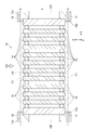
- FIG. 1 is a front view of the laser medium unit.
- FIG. 2 is a cross-sectional view of the laser medium unit taken along the line AA.
- FIG. 3 is a cross-sectional view of the laser medium unit taken along the line BB.
- FIG. 4 is a front view of the laser beam amplifier.
- FIG. 5 is a cross-sectional view taken along the line CC of the laser beam amplifier.
- FIG. 6 is a cross-sectional view of the laser medium unit taken along the line AA when an auxiliary element is provided in the vicinity of the sealing material (O-ring).
- FIG. 7 is a front view of the laser medium (FIG. 7- (A)) and a DD arrow sectional view (FIG. 7- (B)).
- FIG. 7 is a front view of the laser medium (FIG. 7- (A)) and a DD arrow sectional view (FIG. 7- (B)).
- FIG. 7 is a front view of the laser medium (FIG.
- FIG. 8 is a front view of the laser medium (FIG. 8- (A)) and a DD arrow sectional view (FIG. 8- (B)).
- FIG. 9 is a front view of the laser medium (FIG. 9- (A)) and a DD arrow cross-sectional view (FIG. 9- (B)).
- FIG. 10 is a front view of the laser medium (FIG. 10- (A)) and a DD arrow cross-sectional view (FIG. 10- (B)).
- FIG. 11 is a front view of a laser medium (FIG. 11- (A)) and a DD arrow cross-sectional view (FIG. 11- (B)).
- FIG. 12 is a front view of the laser medium (FIG.
- FIG. 13 is a front view of the laser medium (FIG. 13- (A)) and a DD arrow sectional view (FIG. 13- (B)).
- the laser medium the laser medium unit, and the laser beam amplification apparatus according to the embodiment will be described.
- symbol shall be used for the same element and the overlapping description is abbreviate
- FIG. 1 is a front view of the laser medium unit.
- an XYZ three-dimensional orthogonal coordinate system is also shown.
- the traveling direction of the laser light that is the seed light to be amplified is the Y-axis direction, and the two directions perpendicular to the Y-axis are the X-axis direction and the Z-axis direction.
- the laser light amplifying device includes a laser medium unit 10 on which seed light is incident.
- the laser medium unit 10 is a columnar unit including a plurality of flat plate laser media. These laser medium plates are stacked and aligned along the traveling direction of the seed light (the positive direction of the Y axis). From the outside of the laser medium unit 10, the excitation light EX is irradiated into the laser medium. The plurality of excitation lights EX are irradiated from the plurality of light sources toward the central portion of each laser medium.
- the excitation light EX When the excitation light EX is irradiated, the excitation light is incident from the outer peripheral surface of the laser medium, the laser medium is excited, and when the excited laser medium is irradiated with the seed light, the laser light is amplified.
- the wavelength ⁇ 1 of seed light and spontaneous emission light from the laser medium is 1030 nm
- the wavelength ⁇ 2 of excitation light is 940 nm ( ⁇ 1> ⁇ 2).
- the additive concentration of Yb in the laser medium can be preferably set to 0.1 atomic% to 10 atomic%.
- FIG. 2 is a cross-sectional view taken along the line AA of the laser medium unit shown in FIG. 1
- FIG. 3 is a cross-sectional view taken along the line BB of the laser medium unit.
- the laser medium unit 10 includes a pair of metal flanges 11 arranged to face each other, and a plurality of support columns 12 that connect the flanges 11 and adjust the distance between the flanges 11. Although four support columns 12 are shown in FIG. 1, if the number of support columns 12 is three or more, the position of the main surface (XZ plane) of the flange 11 can be easily fixed. That is, since the plane is determined by three points, the main surface position of the flange 11 is uniquely determined by the position of the column by interposing three or more columns between the flanges 11.
- Threaded parts are provided at both ends of the support column 12.
- the flange 11 forms an annular shape having an opening OP, and one flange 11 is provided with an opening (through hole) through which the threaded portion of the support column 12 passes, and the other flange 11 facing the flange 11 has an opening.
- a screw hole for fixing the screw portion of the column 12 is provided, and the screw portion of the column 12 is screwed into the screw hole of the flange 11.
- a plurality of laser medium plates are stacked between the pair of flanges 11. That is, a plurality of disk-shaped and flat laser media 14 are arranged along the Y-axis direction.
- a sealing material 15 is interposed between adjacent laser media 14.
- a window material 16 made of quartz glass or the like is disposed instead of the laser medium 14 at both end positions in the Y-axis direction, and a seal material 15 is interposed between the laser medium 14 and the window material 16.
- the shape of the sealing material 15 is an annular shape, and the material is particularly limited as long as it can maintain airtightness that can prevent the medium from flowing into the space between the laser media 14 from other than the through holes 14a.
- a silicone O-ring or the like can be employed.
- sealing material 15 resin, rubber, glass, ceramics, or a metal such as Cu or Al can be used.
- the laser medium 14 and the sealing material 15 are alternately stacked, and pressure is applied in the Y-axis direction.
- the sealing material 15 may be pressure-bonded on the surface of the laser medium 14. You may adhere with solder or an adhesive.
- the disk-shaped and flat-plate-shaped laser medium 14 includes a through hole 14a extending along the thickness direction (Y-axis direction). .
- one laser medium 14 has one through hole 14a.
- the position (center of gravity position) of the through hole 14a of the first laser medium 14 is 0.
- the position (center of gravity position) of the through hole 14a of the second laser medium 14 is at a position of 180 degrees, and the third laser medium 14 (third laser medium from the left).
- the through hole 14a (the position of the center of gravity) is at a position of 0 degrees.
- the order of the laser medium into which the cooling medium flows first is the first, and the angle of the through hole in the nth laser medium is n ⁇ 180 degrees along the order in which the cooling medium flows. That is, the positions of the through holes 14a of the adjacent pair of laser media 14 are symmetrical with respect to the Y axis passing through the center of the laser media 14 when viewed from the Y-axis direction.
- the disk-shaped and flat window material 16 is also provided with a through hole 16a extending along the thickness direction (Y-axis direction).
- the position of the through hole 16 a of the window member 16 is symmetrical with respect to the Y axis passing through the center of the laser medium 14 adjacent to the window member 16 when viewed from the Y-axis direction.
- the positions of the through holes 14a and the through holes 16a are set so that the traveling direction of the cooling medium flowing in the adjacent space is opposite. Has been. In this case, distortion of the laser beam due to the flow of the cooling medium can be canceled out.
- the material of the laser medium 14 is, for example, a ceramic laser medium.
- the laser medium it is possible to use a glass laser medium with low thermal conductivity, but in order to output laser light with high pulse energy at a high repetition frequency, the thermal conductivity of the laser medium is required from the viewpoint of cooling performance. Higher is preferable.
- a ceramic laser medium has a property equivalent to that of a single crystal and is known to have a higher thermal conductivity than glass or the like, and can output laser light with high pulse energy at a high repetition frequency. By using a glass laser medium, it is possible to obtain a pulse energy that is low in repetition frequency but higher than that of a ceramic laser medium.
- the ceramic laser medium can use, for example, a rare earth metal as a dopant, particularly YAG containing at least one dopant selected from Nd, Yb, Er, Ce, Cr, Cr: Nd and Tm.
- a rare earth metal as a dopant
- YAG containing at least one dopant selected from Nd, Yb, Er, Ce, Cr, Cr: Nd and Tm.
- yttria (Y 2 O 3 ) containing the rare earth metal can be used as a dopant.
- YAG (Y 3 Al 5 O 12 ), Lu 2 O 3 , Sc 2 O 3, or the like can also be used.
- the upper limit of the thickness of the laser medium obtained by the present manufacturing method is about 10 mm
- such a transparent ceramic crystal can use a ceramic laser medium of 10 mm or more.
- the ceramic laser medium has a thickness of 1 mm or more and 20 mm or less
- the structure of the present invention exhibits particularly excellent effects in rigidity, cooling performance, and laser light quality.
- the gain of the laser beam finally output can be made high.
- the laser medium 14 is irradiated with excitation light EX from a plurality of directions along a radial direction perpendicular to the Y axis of the laser medium unit 10. Each laser medium 14 is excited by the excitation light EX.
- the laser light LB as seed light is incident on the laser medium group perpendicularly to the main surface (XZ plane) of the laser medium along one of the window members 16 along the Y axis. The light is transmitted, amplified, and output from the other window member 16.
- the alignment direction of these laser mediums 14 is the same as the longitudinal direction (Y-axis) of the column 12.
- the pressure applied to the sealing material 15 can be adjusted.
- Between the first laser medium and the second laser medium there is a sealing material 15 for maintaining airtightness excluding the through holes.
- the pressure applied to the sealing material 15 by these laser media is low.
- the airtightness excluding the through holes is sufficiently maintained. Since the length between the flanges 11 can be adjusted, the pressure applied to the sealing material 15 between the laser media can be set to a desired value, and the airtightness excluding the through holes in the space between the laser media can be improved. It can be retained sufficiently.
- the sealing material 15 is disposed between the adjacent laser media 14 (referred to as first and second laser media), and the first laser media and the second laser media are along the thickness direction thereof.
- the space between the first laser medium and the second laser medium is an airtight space except for the through holes, and the cooling medium flows therethrough.
- gas inert gas (air, N 2 , CO 2 ), rare gas (Ar, He)) or liquid (heavy water, fluorine-based inert liquid, or the like) can be used.
- Fluorinert TM fluorine inert liquid
- 3M Japan Fluorinert TM (fluorine inert liquid) manufactured by 3M Japan can be used as the fluorinated inert liquid, but as the liquid to be filled, in addition to the fluorinated inert liquid, water, refractive index matching liquid Oils can also be used.
- the excitation light EX is incident on the laser medium 14 to excite the laser medium 14.
- the amplified laser light LB is converted into the laser medium 14. And is output from the window material 16. Since there are a plurality of laser media 14, the multiplication factor is also increased.
- the cooling medium flow path F1 is provided around the laser medium unit 10 and cools the laser medium unit from the outside.
- the space between the first laser medium and the second laser medium is an airtight space excluding the through holes, and the cooling medium flows between the adjacent through holes.
- the flow rate and direction of the cooling medium can be adjusted according to the size and direction of the through hole. Therefore, the laser beam LB passing through the space is affected by the cooling medium flowing on the main surface of the laser medium 14, and adjustment is performed such as reducing the size of the through hole so as to reduce the influence. be able to. Therefore, fluctuations and the like of the amplified laser beam LB are suppressed, and the quality of the laser beam, such as stability and focusing characteristics, is improved.
- the flange 11 is provided with a hole 11b that passes through the flange 11 in the Y-axis direction.
- a tube (not shown) communicates with the outside of the hole 11b, and a cooling medium that contacts the outer surface of the laser medium unit 10 is supplied and discharged from the hole 11b.
- the cooling medium introduced from the hole 11b of one flange 11 flows along the Y-axis direction as indicated by the dotted arrow F1 shown in FIG. 3 while contacting the peripheral surface around the Y-axis of the laser medium 14. It is discharged from the hole 11b of the other flange 11.
- the cooling medium flow path F1 is formed between the laser medium unit 10 and the cylindrical body surrounding it.
- a cylinder may be provided outside the excitation light source when viewed from the laser medium unit 10 (cylinder 24 in FIG. 5), and in addition, provided between the laser medium unit 10 and the excitation light source. It is good (the transparent cylinder 30 of FIG. 5).
- the transparent cylinder 30 transmits the excitation light.
- Transparent material for example, quartz glass.
- a tube for supplying a cooling medium is separately provided in the through hole 16a of the left window member 16 in FIG. 2, and a cooling medium is separately provided in the through hole 16a of the right window member 16.
- emit is provided so that it may connect
- description of the tube is abbreviate
- description of the through-hole 16a is also abbreviate
- the cooling medium can also be introduced from a route other than the window material 16.
- a through-hole can be provided in the sealing material 15 interposed between the window material 16 and the laser medium 14 adjacent thereto. Thereby, a part of the cooling medium flowing through the cooling medium flow path F1 flows into the space between the left window member 16 and the laser medium 14, and is discharged from the space to the cooling medium flow path F1 on the right side. .
- FIG. 4 is a front view of the laser light amplifying device
- FIG. 5 is a cross-sectional view taken along the line CC of the laser light amplifying device.
- the laser beam amplifying apparatus includes the laser medium unit 10 described above, a plurality of excitation light sources 21 that allow excitation light to enter the laser medium unit 10, and a cooling medium flow path F1 disposed around the laser medium unit 10 (FIG. 5). Reference).
- the laser light amplification device amplifies and outputs the laser light LB input into the laser medium unit 10 from a seed light source such as a semiconductor laser element.
- the transparent cylinder 30 described above is disposed around the laser medium unit 10 as necessary to form a cooling medium flow path.
- the excitation light is output from the excitation light source 21. Although the number of the excitation light sources 21 is 12 in the drawing, the number may be 12 or more or 12 or less.
- the excitation light source 21 is fixed to a metal support member 22 in a pair of substantially annular shapes provided outside the laser medium unit 10. Note that the electrode portion of the excitation light source 21 and the support member 22 are insulated.
- the support member 22 has a flange-like lip portion, and an annular insulator 23 is fixed on the lip portion.
- a plurality of terminals 25 are fixed on the insulator 23, and power is supplied from the terminals 25 to the excitation light source 21 via the wiring W.
- the plurality of excitation light sources 21 may be connected in series or may be connected in parallel.
- the support member 22 has a hole 22b penetrating therethrough in the Y-axis direction.
- a tube (not shown) communicates with the hole 22b of one support member 22, the cooling medium is introduced into the second cooling medium flow path F2, and a tube (not shown) communicates with the hole 22b of the other support member 22. Then, the cooling medium is discharged.
- a reflector (reflector) RF may be provided between the excitation light source 21 and the housing 24 so that the excitation light from the excitation light source 21 is efficiently transmitted to the laser medium unit.
- the inner cylindrical surface of the support member 22 having a circular opening is fixed to the outer peripheral surface of the flange 11 of the laser medium unit 10.
- the pair of support members 22 are connected by a cylindrical body 24, and a second cooling medium flow path F ⁇ b> 2 is formed between the inner surface of the cylindrical body 24 and the excitation light source 21.
- the bottom surface of the support member 22 having a circular opening is fixed on the support base 26.
- the structure of the sealing material 15 shown in FIG. 2 is not limited to the above-mentioned thing.
- FIG. 6 is a cross-sectional view taken along the line AA of the laser medium unit when an auxiliary element is provided in the vicinity of the sealing material (O-ring).
- Auxiliary elements 15 a are arranged at both ends in the radial direction of the sealing material 15 to assist sealing with the sealing material 15.
- a spacer having higher rigidity than a silicone O-ring can be used in addition to an adhesive material such as a resin.
- two annular spacers arranged concentrically around the Y axis can be adopted, and an O-ring as the sealing material 15 can be arranged between the annular spacers.
- a glass material or a ceramic can be used in addition to a metal such as Cu or Al.
- the above laser medium unit was prototyped.
- each laser medium made of Nd: YAG has a diameter of 100 mm, a thickness of 10 mm, and a number of 10 sheets, and heavy water flows in the space between the laser media.
- Laser light having a wavelength of 1064 nm was used as seed light, and 12 flash lamps were used as excitation light sources.
- the ceramic laser medium is laminated so that it functions like a large laser rod and has an integral structure, so it can function like a large laser rod, but the flow rate of the cooling medium is Since it can control by a through-hole, the characteristic deterioration of a laser beam can be suppressed.
- the diameter of the column 12 is 2 mm. Further, the overall dimension is about 30 cm, and a laser output of 50 joules or more can be obtained despite its very small size.
- an antireflection film for seed light may be provided on the light incident surface of the main surface (XZ surface) of the window material described above. As a result, the seed light can easily enter the front window material and can be easily emitted from the rear window material. These main surfaces may be subjected to an antireflection treatment other than the antireflection film. Similarly, an antireflection film for seed light may be provided on the light incident surface of the laser medium. These main surfaces may be subjected to an antireflection treatment other than the antireflection film. The antireflection film or the antireflection treatment may be provided not only on the light incident surface of each light transmitting element but also on the light emitting surface.
- a dielectric multilayer film can be used as the antireflection film.
- a dielectric multilayer film a laminate of titanium oxide and silicon oxide is known.
- a refractive index matching liquid having a refractive index equivalent to that of the laser medium can also be used.
- a rare gas flows through the space between laser media, deterioration of the laser medium due to the rare gas is suppressed.
- the above laser medium may be surrounded by a clad material.
- cladding materials that absorb spontaneously emitted light include samarium-added materials, chromium-added materials, and copper-added materials. Specifically, samarium-added YAG, samarium-added glass, chromium-added YAG, chromium-added glass, copper-added YAG, copper-added glass, and the like.
- they are bonded or bonded. In the case of bonding, an adhesive is interposed between them.
- an adhesive such as a resin refractive index matching adhesive or a glass refractive index matching adhesive can be used.
- bonding such as thermal diffusion bonding, optical contact, ion sputtering bonding, etc. can be used.
- the outer surface of the laser medium component and the cladding material are made of ceramics, ceramic sintering bonding is used. Can be used to fix them.
- the material of the antireflection film and the bonding method for the excitation light (808 nm) are the same as those for the seed light or spontaneous emission light.
- the laser medium may be tilted from a plane perpendicular to the Y axis so that adjacent main surfaces that are adjacent to each other are not parallel to each other. Thereby, parasitic oscillation caused by unnecessary reflection by the main surface can be reduced.
- each laser medium need not be a parallel plate as long as it is plate-shaped, and the surface may be slightly inclined.
- a liquid or gas can be used as the above-mentioned cooling medium.
- the liquid water can be used, and as the gas, helium gas or the like can be used.
- the liquid is not limited thereto as long as it has cooling performance.
- the kind of the cooling medium flowing through the cooling medium flow path F1 and the cooling medium flowing through the space between the laser media can be different. In the most appropriate combination, water is used as the former cooling medium and helium is used as the latter cooling medium. Thereby, the influence of the distortion of the laser beam by a cooling medium can be suppressed more suitably.
- the through-hole shape of the above-mentioned laser medium can be variously modified.
- FIG. 8 is a front view of the laser medium (FIG. 8- (A)) and a DD arrow sectional view (FIG. 8- (B)).
- the number of through-holes 14a is two, and in the XZ plane, the Z-axis direction is 0 degrees, and they exist at positions of 0 degrees and 180 degrees.
- the direction and flow rate of the cooling medium can be adjusted more precisely.
- FIG. 9 is a front view of the laser medium (FIG. 9- (A)) and a DD arrow sectional view (FIG. 9- (B)).
- the direction and flow rate of the cooling medium can be adjusted more precisely. Further, when three through holes are arranged at equal angular positions, there is an effect that a large amount of cooling medium can flow at a lower speed than in the case of two through holes.
- FIG. 10 is a front view of the laser medium (FIG. 10- (A)) and a DD arrow sectional view (FIG. 10- (B)).
- the opening shape of the through hole 14 a is an arc shape along the outer periphery of the laser medium 14.
- the arc opening angle ⁇ 4 can be set to 10 to 180 degrees. In this case, from the viewpoint of the flow rate and direction stability of the cooling medium, there is an effect that a large amount of the cooling medium can flow stably at a low speed in one direction.
- FIG. 11 is a front view of the laser medium (FIG. 11- (A)) and a DD arrow sectional view (FIG. 11- (B)).
- the through hole 14 a extends obliquely with respect to the thickness direction (Y axis) of the laser medium 14.
- the angle formed by the central axis of the through-hole 14a with the Y-axis can be set to 10 to 80 degrees, and can be set to 30 degrees or more and 80 degrees or less in order to suppress vortex flow caused by fluid collision with the adjacent laser medium.
- the cooling medium can be flowed stably by giving directivity to the flow direction.
- FIG. 12 is a front view of the laser medium (FIG. 12- (A)) and a DD arrow cross-sectional view (FIG. 12- (B)).
- the through hole 14a has a tapered shape.
- the through hole 14a is tapered with respect to the traveling direction of the cooling medium, from the viewpoint of the flow rate of the cooling medium, the stability of the direction, etc., the effect that the cooling performance can be improved by positively generating turbulent flow. There is.
- FIG. 13 is a front view of the laser medium (FIG. 13- (A)) and a DD arrow cross-sectional view (FIG. 13- (B)).
- the through holes 14 a are arranged in an annular shape along the outer periphery of the laser medium 14.
- the number of through-holes 14a is not limited to this, and may be more or less. In this case, from the viewpoint of the flow rate and direction stability of the cooling medium, there is an effect that a large amount of the cooling medium can be stably flowed at a low speed in the uniform direction.
- the plurality of laser media 14 are stacked along the thickness direction, and a sealing material is provided between adjacent laser media. Intervene.
- the cooling medium flows through the through holes of the laser media.
- the cooling medium can function like a large laser rod.
- the flow rate of the cooling medium can be controlled by the through-hole, it is possible to suppress deterioration of the laser light characteristics.
- the laser medium unit sets an XYZ three-dimensional orthogonal coordinate system and the stacking direction of the plurality of laser media 14 is the Y axis
- the positions of the through holes 14a of the adjacent laser media in the XZ plane are different. Is present (see FIG. 2).
- the flow path of the cooling medium flowing between them can be controlled.
- the laser beam amplifying apparatus (see FIG. 5) using the above-described laser medium unit 10 includes the laser medium unit 10, the excitation light source 21 that makes the excitation light incident in the laser medium unit 10, and the laser medium 14.
- a means for supplying a cooling medium into the hole 14 a (through hole 16 a of the window member 16 and the like) and a cooling medium flow path F ⁇ b> 1 disposed around the laser medium unit 10 are provided.
- the excitation light is incident on the laser medium 14 to excite the laser medium 14.
- the amplified laser light is output from the laser medium 14.
- the multiplication factor is also increased.
- the flow velocity of the cooling medium that is output from the through hole 14a and flows through the space between the cooling medium is small, but the cooling performance is deteriorated. Therefore, by providing the cooling medium flow path F1 also around the laser medium unit 10, the laser medium is sufficiently cooled while suppressing the deterioration of the cooling performance due to only the through hole 14a, and the characteristics of the laser medium itself are improved. By stabilizing, it is possible to further suppress the deterioration of the quality of the laser beam, such as the stability and focusing characteristics, and to output a high-quality laser beam.
- the position of the laser medium described above can be rotated around the Y axis.
- it can be arranged by rotating 180 degrees, 90 degrees, or 30 degrees, for example.
- the heated cooling medium receives a force in the positive direction of the Z axis.
- the positions of the through holes 14a include those located at 0 ° with the positive direction of the Z-axis being 0 °. Further, it is preferable to set the rotation angle.
Abstract
Description
Claims (9)
- 冷却媒体を流通させるための貫通孔を有する板状のレーザ媒質。 A plate-shaped laser medium having a through hole for circulating a cooling medium.
- 前記貫通孔の数は、2以上であることを特徴とする請求項1に記載のレーザ媒質。 The laser medium according to claim 1, wherein the number of the through holes is two or more.
- 前記貫通孔の開口形状は、前記レーザ媒質の外周に沿った弧状である、ことを特徴とする請求項1に記載のレーザ媒質。 2. The laser medium according to claim 1, wherein the opening shape of the through hole is an arc shape along an outer periphery of the laser medium.
- 前記貫通孔は、前記レーザ媒質の厚み方向に対して、斜めに延びていることを特徴とする請求項1に記載のレーザ媒質。 The laser medium according to claim 1, wherein the through hole extends obliquely with respect to a thickness direction of the laser medium.
- 前記貫通孔は、先細り形状を有していることを特徴とする請求項1に記載のレーザ媒質。 The laser medium according to claim 1, wherein the through hole has a tapered shape.
- 前記貫通孔は、前記レーザ媒質の外周に沿って、環状に並んでいる、ことを特徴とする請求項1に記載のレーザ媒質。 The laser medium according to claim 1, wherein the through holes are arranged in a ring shape along an outer periphery of the laser medium.
- 請求項1~6のいずれか一項に記載の前記レーザ媒質を複数備えるレーザ媒質ユニットであって、
複数の前記レーザ媒質は、その厚み方向に沿って積層され、
隣接する前記レーザ媒質間にはシール材が介在している、ことを特徴とするレーザ媒質ユニット。 A laser medium unit comprising a plurality of the laser medium according to any one of claims 1 to 6,
The plurality of laser media are stacked along the thickness direction,
A laser medium unit, wherein a sealing material is interposed between adjacent laser media. - XYZ三次元直交座標系を設定し、
複数の前記レーザ媒質の積層方向をY軸とした場合、
隣接する前記レーザ媒質の前記貫通孔のXZ平面内における位置は、異なっているものが存在する、ことを特徴とする請求項7に記載のレーザ媒質ユニット。 Set XYZ 3D Cartesian coordinate system,
When the stacking direction of the plurality of laser media is the Y axis,
8. The laser medium unit according to claim 7, wherein there are different positions in the XZ plane of the through holes of the adjacent laser medium. - 請求項7又は請求項8に記載のレーザ媒質ユニットと、
前記レーザ媒質ユニット内に励起光を入射させる励起光源と、
前記レーザ媒質の前記貫通孔内に冷却媒体を供給する手段と、
前記レーザ媒質ユニットの周囲に配置された冷却媒体流路と、
を備えることを特徴とするレーザ光増幅装置。 The laser medium unit according to claim 7 or 8,
An excitation light source for causing excitation light to enter the laser medium unit;
Means for supplying a cooling medium into the through hole of the laser medium;
A cooling medium flow path disposed around the laser medium unit;
A laser light amplifying apparatus comprising:
Priority Applications (3)
| Application Number | Priority Date | Filing Date | Title |
|---|---|---|---|
| GB1711358.0A GB2551654B (en) | 2015-01-20 | 2016-01-13 | Laser medium, laser medium unit, and laser beam amplification device |
| DE112016000395.1T DE112016000395T5 (en) | 2015-01-20 | 2016-01-13 | LASER MEDIUM, LASER MEDIA UNIT, AND LASER BEAM GAIN ARRANGEMENT |
| US15/544,613 US10374377B2 (en) | 2015-01-20 | 2016-01-13 | Laser medium, laser medium unit, and laser beam amplification device |
Applications Claiming Priority (2)
| Application Number | Priority Date | Filing Date | Title |
|---|---|---|---|
| JP2015-008808 | 2015-01-20 | ||
| JP2015008808A JP6584778B2 (en) | 2015-01-20 | 2015-01-20 | Laser medium unit and laser amplifier |
Publications (1)
| Publication Number | Publication Date |
|---|---|
| WO2016117426A1 true WO2016117426A1 (en) | 2016-07-28 |
Family
ID=56416973
Family Applications (1)
| Application Number | Title | Priority Date | Filing Date |
|---|---|---|---|
| PCT/JP2016/050809 WO2016117426A1 (en) | 2015-01-20 | 2016-01-13 | Laser medium, laser medium unit, and laser beam amplification device |
Country Status (5)
| Country | Link |
|---|---|
| US (1) | US10374377B2 (en) |
| JP (1) | JP6584778B2 (en) |
| DE (1) | DE112016000395T5 (en) |
| GB (1) | GB2551654B (en) |
| WO (1) | WO2016117426A1 (en) |
Families Citing this family (1)
| Publication number | Priority date | Publication date | Assignee | Title |
|---|---|---|---|---|
| JP7008055B2 (en) | 2019-07-12 | 2022-01-25 | 浜松ホトニクス株式会社 | Laser medium unit and laser light amplifier |
Citations (5)
| Publication number | Priority date | Publication date | Assignee | Title |
|---|---|---|---|---|
| US3611190A (en) * | 1969-10-16 | 1971-10-05 | American Optical Corp | Laser structure with a segmented laser rod |
| US3715682A (en) * | 1970-03-19 | 1973-02-06 | American Optical Corp | Rectangular disc laser |
| US3766493A (en) * | 1972-09-26 | 1973-10-16 | Us Navy | Holding cladding for laser slabs |
| JPS62234386A (en) * | 1985-12-28 | 1987-10-14 | カ−ル・ツワイス・ステイフツング | Solid state laser oscillator |
| JPH02209778A (en) * | 1989-02-09 | 1990-08-21 | Brother Ind Ltd | Solid state laser apparatus |
Family Cites Families (4)
| Publication number | Priority date | Publication date | Assignee | Title |
|---|---|---|---|---|
| US3628172A (en) | 1970-03-19 | 1971-12-14 | North American Rockwell | High-power dissipation laser segment mounting holders |
| US4134084A (en) | 1976-09-29 | 1979-01-09 | Owens-Illinois, Inc. | Hybrid laser structures |
| US6813289B2 (en) | 2001-07-25 | 2004-11-02 | Innotech, Usa, Inc. | Portable laser device |
| EP1454386B1 (en) | 2001-11-21 | 2007-02-14 | General Atomics | Laser containing a distributed gain medium |
-
2015
- 2015-01-20 JP JP2015008808A patent/JP6584778B2/en active Active
-
2016
- 2016-01-13 GB GB1711358.0A patent/GB2551654B/en active Active
- 2016-01-13 US US15/544,613 patent/US10374377B2/en active Active
- 2016-01-13 WO PCT/JP2016/050809 patent/WO2016117426A1/en active Application Filing
- 2016-01-13 DE DE112016000395.1T patent/DE112016000395T5/en active Pending
Patent Citations (5)
| Publication number | Priority date | Publication date | Assignee | Title |
|---|---|---|---|---|
| US3611190A (en) * | 1969-10-16 | 1971-10-05 | American Optical Corp | Laser structure with a segmented laser rod |
| US3715682A (en) * | 1970-03-19 | 1973-02-06 | American Optical Corp | Rectangular disc laser |
| US3766493A (en) * | 1972-09-26 | 1973-10-16 | Us Navy | Holding cladding for laser slabs |
| JPS62234386A (en) * | 1985-12-28 | 1987-10-14 | カ−ル・ツワイス・ステイフツング | Solid state laser oscillator |
| JPH02209778A (en) * | 1989-02-09 | 1990-08-21 | Brother Ind Ltd | Solid state laser apparatus |
Also Published As
| Publication number | Publication date |
|---|---|
| GB201711358D0 (en) | 2017-08-30 |
| JP2016134528A (en) | 2016-07-25 |
| DE112016000395T5 (en) | 2017-09-28 |
| US20180278007A1 (en) | 2018-09-27 |
| GB2551654B (en) | 2019-05-01 |
| US10374377B2 (en) | 2019-08-06 |
| JP6584778B2 (en) | 2019-10-02 |
| GB2551654A (en) | 2017-12-27 |
Similar Documents
| Publication | Publication Date | Title |
|---|---|---|
| JP5330801B2 (en) | Laser gain medium, laser oscillator and laser amplifier | |
| JP2004349701A (en) | Method for generating diode pump solid disk laser and uniform laser gain | |
| JP6393196B2 (en) | Laser light amplifier | |
| WO2016117426A1 (en) | Laser medium, laser medium unit, and laser beam amplification device | |
| US20150028231A1 (en) | Laser apparatus | |
| CN112072464B (en) | Light source device | |
| JP6728339B2 (en) | Waveguide forming method and apparatus | |
| JP7008055B2 (en) | Laser medium unit and laser light amplifier | |
| CN105324890A (en) | Radially polarized thin disk laser | |
| US9209588B2 (en) | Disk laser | |
| US9685756B2 (en) | Laser amplifier, laser apparatus, and extreme ultraviolet light generating system | |
| TWI524610B (en) | Gas laser device | |
| JPWO2012137259A1 (en) | Solid state laser equipment | |
| JP6083709B2 (en) | Solid state laser equipment | |
| US20140348189A1 (en) | Laser apparatus | |
| WO2007144645A1 (en) | Light amplification device | |
| TWM421634U (en) | Solid-state laser amplifier |
Legal Events
| Date | Code | Title | Description |
|---|---|---|---|
| 121 | Ep: the epo has been informed by wipo that ep was designated in this application |
Ref document number: 16740033 Country of ref document: EP Kind code of ref document: A1 |
|
| ENP | Entry into the national phase |
Ref document number: 201711358 Country of ref document: GB Kind code of ref document: A Free format text: PCT FILING DATE = 20160113 |
|
| WWE | Wipo information: entry into national phase |
Ref document number: 15544613 Country of ref document: US |
|
| WWE | Wipo information: entry into national phase |
Ref document number: 112016000395 Country of ref document: DE |
|
| 122 | Ep: pct application non-entry in european phase |
Ref document number: 16740033 Country of ref document: EP Kind code of ref document: A1 |