WO2016115961A1 - 物联网架构下基于证人节点的矿井运动目标增强定位方法 - Google Patents
物联网架构下基于证人节点的矿井运动目标增强定位方法 Download PDFInfo
- Publication number
- WO2016115961A1 WO2016115961A1 PCT/CN2015/099316 CN2015099316W WO2016115961A1 WO 2016115961 A1 WO2016115961 A1 WO 2016115961A1 CN 2015099316 W CN2015099316 W CN 2015099316W WO 2016115961 A1 WO2016115961 A1 WO 2016115961A1
- Authority
- WO
- WIPO (PCT)
- Prior art keywords
- moving target
- witness
- node
- positioning
- search
- Prior art date
- Legal status (The legal status is an assumption and is not a legal conclusion. Google has not performed a legal analysis and makes no representation as to the accuracy of the status listed.)
- Ceased
Links
Images
Classifications
-
- H—ELECTRICITY
- H04—ELECTRIC COMMUNICATION TECHNIQUE
- H04W—WIRELESS COMMUNICATION NETWORKS
- H04W4/00—Services specially adapted for wireless communication networks; Facilities therefor
- H04W4/02—Services making use of location information
-
- H—ELECTRICITY
- H04—ELECTRIC COMMUNICATION TECHNIQUE
- H04W—WIRELESS COMMUNICATION NETWORKS
- H04W4/00—Services specially adapted for wireless communication networks; Facilities therefor
- H04W4/02—Services making use of location information
- H04W4/029—Location-based management or tracking services
-
- G—PHYSICS
- G01—MEASURING; TESTING
- G01S—RADIO DIRECTION-FINDING; RADIO NAVIGATION; DETERMINING DISTANCE OR VELOCITY BY USE OF RADIO WAVES; LOCATING OR PRESENCE-DETECTING BY USE OF THE REFLECTION OR RERADIATION OF RADIO WAVES; ANALOGOUS ARRANGEMENTS USING OTHER WAVES
- G01S5/00—Position-fixing by co-ordinating two or more direction or position line determinations; Position-fixing by co-ordinating two or more distance determinations
- G01S5/02—Position-fixing by co-ordinating two or more direction or position line determinations; Position-fixing by co-ordinating two or more distance determinations using radio waves
- G01S5/12—Position-fixing by co-ordinating two or more direction or position line determinations; Position-fixing by co-ordinating two or more distance determinations using radio waves by co-ordinating position lines of different shape, e.g. hyperbolic, circular, elliptical or radial
Definitions
- the invention relates to a method for enhancing the positioning of a mine moving target, in particular to an enhanced positioning method for a mine moving target based on a witness node under the Internet of Things architecture.
- the positioning algorithm can be divided into two categories: ranging and non-ranging.
- the non-ranging algorithm is simple to implement, the positioning accuracy is not high, and most of the algorithms are not suitable for narrow and narrow roadway environments, such as centroid algorithm and dv-hop algorithm.
- the algorithm based on ranging is widely used in coal mine underground positioning.
- the RSSI-based positioning algorithm is the most widely used because of its simple principle and easy hardware implementation.
- the fading of the signal in the coal mine roadway is extremely irregular, and it is difficult to establish a suitable signal attenuation model, which makes the RSSI-based positioning algorithm less accurate and the accuracy changes with time.
- Other commonly used algorithms based on ranging such as DOA, TOA, etc. High-precision hardware equipment is required, and it is affected by various conditions, and the positioning accuracy is not ideal or expensive.
- the mine positioning system based solely on the existing positioning algorithm is difficult to meet the requirements of the mine safety production for positioning accuracy.
- the mine Internet of Things With the construction and development of the mine Internet of Things, a large number of sensor nodes with different functions will be deployed in the coal mine to conduct real-time sensing, monitoring and early warning of the coal mine environment, production equipment and production personnel.
- the object-to-material connection and information intercommunication between different nodes is its basic function, which allows these sensing nodes to provide auxiliary services for the positioning system.
- the ground-based IoT management platform manages the equipment of the entire mine. The location of these devices and sensors is stored in the database, and the platform can coordinate the nodes of these non-positioning systems to assist in downhole positioning.
- the object of the present invention is to provide an enhanced positioning method for a mine moving target based on a witness node under the Internet of Things architecture, so as to improve the positioning accuracy without replacing the existing positioning system.
- the object of the present invention is achieved by: the moving target enhanced positioning method: the moving target travels in the roadway, and the existing downhole positioning system locates the initial positioning coordinate point tp(i); then, the initial positioning coordinate point is Tp(i) is projected onto the middle line of the roadway to obtain the projection point tp'(i).
- the sensing node whose projection point tp'(i) is within the maximum communication distance is searched; finally, the perception is As a witness node, the node corrects the obtained initial positioning coordinate points by the witness node enhanced positioning method, and enhances the positioning accuracy of the moving target; the specific steps are as follows:
- the moving target communicates with the downhole positioning system during the course of the roadway, and the initial positioning coordinate point tp(i) is obtained by the downhole positioning algorithm;
- the obtained initial positioning coordinate point is corrected by the witness node enhanced positioning method to obtain the final positioning coordinate point rp(i).
- the steps of the witness node enhanced positioning method are as follows:
- Step 1 Determine whether the number of sensing nodes n satisfies the following conditions
- step 1 is divided into the following two cases:
- n there is a witness node near the moving target.
- the base station closest to the moving target is taken as another witness node from the IoT management platform, and the two witness nodes respectively use sp i (1), Sp i (2) indicates that the coordinates are (x i1 , y i1 ), (x i2 , y i2 ), respectively;
- the two sensing nodes closest to the distance tp'(i) are used as witness nodes, and the two witness nodes are respectively represented by sp i (1) and sp i (2), and their coordinates are respectively ( x i1 , y i1 ), (x i2 , y i2 );
- Step 2 Calculate the distances from the projection point tp'(i) to the witness nodes sp i (1) and sp i (2) respectively to d i (1), d i (2); find the pass sp i (1) , sp i (2) a straight line l 1: (1) parallel to the center line through the tunnel sp i of the straight line l 2, by sp i (2) and a straight line parallel to the roadway centerline l 3.
- Step 3 Adjust the transmit power of the witness node, determine the search area with radius d i (j), search for the moving target, and classify the two situations according to whether the moving target can be searched:
- the moving target is in the range of the concentric ring with sp i (j) as the center, that is, within the range composed of 12 rings, and the formula is satisfied at this time.
- the moving target is in the range of the concentric ring with sp i (j) as the center, that is, within the range composed of 34 rings, and the formula is satisfied at this time.
- Step 4 Perform tp(i) correction on the initial anchor point based on two witness nodes
- Step 3 After sp i (1), sp i (2) perform an iterated search, Step 3 for analysis sp i (1), sp i (2) relevant to the type of initial and corrected setpoint.
- sp i (1), sp i (2) belong to the b class in case 2, the witness node can not play a role, tp (i) is the final positioning coordinate point rp (i);
- the moving target is in the intersection of the center of sp i (1) and sp i (2), and there is two intersections between the straight line l 1 and the boundary of the intersecting area, and the midpoint rp of the two intersection points is calculated.
- '(i) if there is no intersection in the search result area of sp i (1), sp i (2), take the inner arc of the left ring result of the left witness node and the left result ring of the right witness node.
- the inner arc, l 1 and the two arcs each have an intersection point, and calculate the midpoint rp'(i) of the two intersection points;
- Step 5 Project rp'(i) onto the lane center line, and the center line projection point is the final positioning coordinate point rp(i).
- the mine moving target enhanced positioning method based on the witness node in the Internet of Things architecture of the present invention travels in the roadway through the moving target, and the downhole positioning system locates it, and obtains the initial positioning coordinate point tp(i). Then, the initial positioning coordinate point tp(i) is projected onto the lane center line to obtain the projection point tp'(i), and the distance of the projection point tp'(i) is searched for the maximum communication distance range by using the Internet of Things management platform.
- the perceptual node is used as the witness node, and the initial positioning coordinates are obtained by the witness node enhanced positioning method. Line correction to enhance the positioning accuracy of moving targets.
- the positioning system provides initial positioning values for moving targets. Since this preliminary positioning result is not necessarily accurate, it is necessary to have other nodes that accurately know their position to testify to prove whether the moving target is at the position of the positioning result, and the corresponding node providing the proof is the witness node. These sensing nodes are used as witness nodes to judge whether the positioning result obtained by the positioning system is accurate. If the positioning accuracy is low, the operation command is sent to the witness node through the ground-based IoT management platform to correct the positioning result and improve the positioning accuracy.
- This method realizes the effective combination of the positioning system and the sensing node under the Internet of Things architecture. On the basis of not changing the original positioning system under the mine, the system is optimized and upgraded, and the moving target positioning accuracy is improved, which has good practicability. And ease of use.
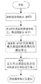
- 1 is a flow chart of the overall algorithm of the present invention.
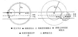
- FIG. 2 is a schematic diagram of an enhancement algorithm when the nearest and next-most witness nodes of the present invention are finally capable of searching for a moving target.
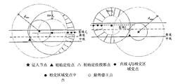
- FIG. 3 is a schematic diagram of an enhancement algorithm when the nearest and next-most witness nodes of the present invention are finally unable to search for a moving target.
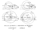
- FIG. 4 is a partial schematic diagram of an enhancement algorithm when the two witness nodes of the present invention can finally search for a moving target at the same time.
- the mine moving target enhanced positioning method based on the witness node travels through the moving target in the roadway, and the existing downhole positioning system locates the initial positioning coordinate point tp(i). Then, the initial positioning coordinate point tp(i) is projected onto the lane center line to obtain the projection point tp'(i), and the distance of the projection point tp'(i) is searched within the maximum communication distance range by using the Internet of Things management platform. Perceive the node. Finally, the sensory node is used as the witness node, and the initial positioning coordinate points are corrected by the witness node enhanced positioning method to enhance the positioning accuracy of the moving target. Specific steps are as follows:
- the moving target communicates with the downhole positioning system during the roadway travel, and the initial positioning coordinate point tp(i) is obtained by the downhole positioning algorithm.
- the sensing node whose distance of the projection point is within the maximum communication distance range, that is, the maximum search radius d max is searched, and the number of sensing nodes n and the coordinates of the sensing node are recorded.
- the obtained initial positioning coordinate point is corrected by the witness node enhanced positioning method to obtain the final positioning coordinate point rp(i).
- the steps of the witness node enhanced positioning method are as follows:
- Step 1 Determine whether the number of sensing nodes n satisfies the following conditions
- step 1 is divided into the following two cases:
- n there is a witness node near the moving target.
- the base station closest to the moving target is taken as another witness node from the IoT management platform, and the two witness nodes respectively use sp i (1), Sp i (2) indicates that the coordinates are (x i1 , y i1 ), (x i2 , y i2 ), respectively;
- the two sensing nodes closest to the distance tp'(i) are used as witness nodes, and the two witness nodes are respectively represented by sp i (1) and sp i (2), and their coordinates are respectively ( x i1 , y i1 ), (x i2 , y i2 );
- Step 2 Calculate the distances from the projection point tp'(i) to the witness nodes sp i (1) and sp i (2) respectively to d i (1), d i (2); find the pass sp i (1) , sp i (2) a straight line l 1: (1) parallel to the center line through the tunnel sp i of the straight line l 2, by sp i (2) and a straight line parallel to the roadway centerline l 3.
- Set the moving target positioning accuracy range to r o 3 meters;
- Step 3 Adjust the transmit power of the witness node, determine the search area with radius d i (j), search for the moving target, and classify the two situations according to whether the moving target can be searched:
- the moving target is in the range of the concentric ring with sp i (j) as the center, that is, within the range composed of 12 rings, and the formula is satisfied at this time.
- the moving target is in the range of the concentric ring with sp i (j) as the center, that is, within the range composed of 34 rings, and the formula is satisfied at this time.
- Step 4 Perform tp(i) correction on the initial anchor point based on two witness nodes
- Step 3 After sp i (1), sp i (2) perform an iterated search, Step 3 for analysis sp i (1), sp i (2) relevant to the type of initial and corrected setpoint.
- sp i (1), sp i (2) belong to the b class in case 2, the witness node can not play a role, tp (i) is the final positioning coordinate point rp (i);
- the moving target is in the intersection of the center of sp i (1) and sp i (2), and there is two intersections between the straight line l 1 and the boundary of the intersecting area, and the midpoint rp of the two intersection points is calculated.
- '(i) if there is no intersection in the search result area of sp i (1), sp i (2), take the inner arc of the left ring result of the left witness node and the left result ring of the right witness node.
- the inner arc, l 1 and the two arcs each have an intersection point, and calculate the midpoint rp'(i) of the two intersection points, as shown in FIG. 4;
- Step 5 Project rp'(i) onto the middle line of the roadway.
- the center line projection point is the final positioning coordinate point rp(i), as shown in Figures 2, 3 and 4.
Landscapes
- Engineering & Computer Science (AREA)
- Computer Networks & Wireless Communication (AREA)
- Signal Processing (AREA)
- Physics & Mathematics (AREA)
- General Physics & Mathematics (AREA)
- Radar, Positioning & Navigation (AREA)
- Remote Sensing (AREA)
- Position Fixing By Use Of Radio Waves (AREA)
Abstract
一种物联网架构下基于证人节点的矿井运动目标增强定位方法,属于矿井运动目标增强定位方法。运动目标在巷道中行进,现有井下定位系统对其进行定位,得到初始定位坐标点tp(i);然后,将初始定位坐标点tp(i)投影到巷道中线上,得到投影点tp'(i),利用物联网管控平台,搜索到投影点tp'(i)的距离在最大通信距离范围内的感知节点;最后,将感知节点作为证人节点,通过证人节点增强定位方法对得到的初始定位坐标点进行修正,增强运动目标的定位精度。该方法在物联网架构下实现定位系统与感知节点的有效结合,在不改变矿井下原有定位系统的基础上,实现系统的优化升级,提高运动目标定位精度,具有很好的实用性和易用性。
Description
本发明涉及一种矿井运动目标增强定位方法,特别是一种物联网架构下基于证人节点的矿井运动目标增强定位方法。
煤矿井下的特殊环境使得无线信号的传播存在严重的非视距和多径衰落现象,进而制约着常规定位技术在井下使用时的定位精度。
根据定位过程中是否需要测量距离,可以将定位算法分成测距和非测距两大类。基于非测距的算法虽然实现简单,但定位精度不高,而且多数算法不适用于井下狭长的巷道环境,如质心算法、dv-hop算法等。基于测距的算法在煤矿井下定位中应用较多,其中基于RSSI的定位算法因其原理简单、硬件实现容易等优势应用最为广泛。但是煤矿巷道中信号的衰落极不规律,难以建立合适的信号衰减模型,致使基于RSSI的定位算法精度不高且精度随着时间而变化;其它基于测距的常用算法,例如DOA、TOA等,需要高精度的硬件设备配合,并且受多种条件影响,定位精度不理想或者价格昂贵。
可见,单纯基于现有定位算法的矿井定位系统难以满足矿井安全生产对定位精度的要求。随着矿山物联网的建设与发展,煤矿井下将会部署大量不同功能的传感器节点,对煤矿环境、生产设备和生产人员进行实时感知、监测、预警等。在物联网架构下,不同节点之间实现物-物相连和信息互通是其基本功能,可以让这些感知节点为定位系统提供辅助服务;同时,地面的物联网管控平台管理着整个矿井的设备,数据库中存有这些设备和传感器的安装位置,平台可以协调这些非定位系统的节点为井下定位提供帮助。
发明内容
本发明的目的是要提供一种物联网架构下基于证人节点的矿井运动目标增强定位方法,实现在不替代已有定位系统基础上提高定位精度。
本发明的目的是这样实现的:该运动目标增强定位方法:运动目标在巷道中行进,现有井下定位系统对其进行定位,得到初始定位坐标点tp(i);然后,将初始定位坐标点tp(i)投影到巷道中线上,得到投影点tp'(i),利用物联网管控平台,搜索到投影点tp'(i)的距离在最大通信距离范围内的感知节点;最后,将感知节点作为证人节点,通过证人节点增强定位方法对得到的初始定位坐标点进行修正,增强运动目标的定位精度;具体步骤如下:
(1)移动目标在巷道行进的过程中与井下定位系统进行通信,通过井下定位算法得到初始定位坐标点tp(i);
(2)将初始定位坐标点tp(i)投影到巷道中线上,得到投影点tp'(i);
(3)已知感知节点最大发射功率pmax,得到感知节点最大搜索半径dmax;
(4)利用物联网管控平台,搜索到投影点的距离在最大通信距离范围即最大搜索半径dmax内的感知节点,并记录感知节点个数n及感知节点坐标;
(5)将感知节点作为证人节点,通过证人节点增强定位方法对得到的初始定位坐标点进行修正,得到最终定位坐标点rp(i)。
所述的证人节点增强定位方法步骤如下:
步骤1:判断感知节点个数n满足下列哪种条件;
(1)当n=0时,在运动目标附近没有证人节点,无法对初始定位坐标点tp(i)进行修正,不需要进行下面步骤的处理,直接输出结果,tp(i)即为最终定位坐标点rp(i);
(2)当n>=1时,步骤1分为下列两种情况处理:
a.当n=1时,在运动目标附近有一个证人节点,这时从物联网管控平台中取距离运动目标最近的基站作为另一个证人节点,两个证人节点分别用spi(1)、spi(2)表示,其坐标分别为(xi1,yi1)、(xi2,yi2);
b.当n>=2时,取距离tp'(i)最近的两个感知节点作为证人节点,两个证人节点分别用spi(1)、spi(2)表示,其坐标分别为(xi1,yi1)、(xi2,yi2);
步骤2:计算投影点tp'(i)到证人节点spi(1)、spi(2)的距离分别对应为di(1)、di(2);求出通过spi(1)、spi(2)的直线l1: 通过spi(1)平行于巷道中线的直线l2,通过spi(2)且平行于巷道中线的直线l3。设置运动目标定位精度范围为ro米;
步骤3:调整证人节点发射功率,确定以di(j)为半径的搜索区域,对运动目标进行搜索,并根据是否能够搜索到运动目标,分为2种情况概述:
情况1:证人节点在以di(j),j=1,2为半径的搜索区域内能够搜索到运动目标时,调整发射功率,使得搜索半径每次向内压缩ro米,即以(di(j)-count×ro)为半径对运动目标进行迭代搜索,直到证人节点第m次搜索不到运动目标或者满足di(j)-m×ro<ro条件为止;其中,count=1,…,m;di(j)>m×ro;m为总迭代搜索次数;
a.证人节点第m次搜索不到运动目标时,运动目标在以spi(j)为圆心的同心圆环所组成的范围内,即在①②圆环所组成的范围内,此时满足公式(1):
R2=(x-xij)2+(y-yij)2 ① r2=(x-xij)2+(y-yij)2 ②
r2≤(x-xij)2+(y-yij)2≤R2 (1)
其中,R=di(j)-(m-1)×ro,r=di(j)-m×ro;
b.满足di(j)-m×ro<ro条件时,说明运动目标在以spi(j)为圆心,(di(j)-m×ro)为半径的最小圆范围内,此时满足公式(2):
(x-xij)2+(y-yij)2≤r2 (2)
其中,r=di(j)-m×ro;
情况2:证人节点在以di(1)为半径的搜索区域内不能搜索到运动目标时,调整发射功率,使得搜索半径每次向外扩展ro米,即以(di(j)+count×ro)为半径对运动目标进行迭
代搜索,直到证人节点在第m次搜索到运动目标或者dmax范围内搜索不到证人节点为止;其中,count=1,…,m;(di(j)+m×ro)<dmax;m为总迭代搜索次数;
a.当证人节点第m次搜索到运动目标时,运动目标在以spi(j)为圆心的同心圆环所组成的范围内,即在③④圆环所组成的范围内,此时满足公式(3):
R'2=(x-xij)2+(y-yij)2 ③ r'2=(x-xij)2+(y-yij)2 ④
r'2≤(x-xij)2+(y-yij)2≤R'2 (3)
其中,R'=di(j)+m×ro,r'=di(j)+(m-1)×ro;
b.dmax范围内搜索不到证人节点时,说明运动目标在最大扩展范围内搜索不到运动目标,此时满足公式(4):
(di(j)+m×ro)>dmax (4)
步骤4:基于两个证人节点对初始定位点进行tp(i)修正
对spi(1),spi(2)进行迭代搜索后,针对步骤3分析spi(1),spi(2)所属类型并修正初始定位点。
(1)spi(1),spi(2)同属于情况2中的b类时,证人节点不能发挥作用,tp(i)即为最终定位坐标点rp(i);
(2)spi(1)、spi(2)中有一个属于情况1中的a类,一个属于情况2中的b类时,只有一个证人节点能够搜索到目标节点而真正起到“证人”的作用,当运动目标在以spi(1)为圆心的双圆环内,以spi(2)为圆心,以dmax为半径的圆外时,如果有一侧交叉区域,可以确定运动目标的区域范围,直线l2与运动目标所在区域边界有两个交点,计算两个交点的中点rp'(i);否则存在两个交叉区域,此时选择距离定位初值较近的一个阴影区域作为运动目标所在的区域,并用同样方法得到rp'(i);
当运动目标在以spi(2)为圆心的双圆环内,以spi(1)为圆心,以dmax为半径的圆外时,同理可求rp'(i);
(3)非上述情况时,运动目标在以spi(1),spi(2)为圆心的相交区域内,直线l1与相交区域边界有两个交点,计算两个交点的中点rp'(i),如果spi(1),spi(2)的搜索结果区域不存在交叉,则取左边证人节点的右边结果圆环区域的内圆弧、右边证人节点的左边结果圆环的内圆弧,l1与这两个圆弧各有一个交点,计算两个交点的中点rp'(i);
步骤5:将rp'(i)投影到巷道中线上,中线投影点即为最终定位坐标点rp(i)。
有益效果:由于采用上述技术方案,本发明的物联网架构下基于证人节点的矿井运动目标增强定位方法通过运动目标在巷道中行进,井下定位系统对其进行定位,得到初始定位坐标点tp(i);然后,将初始定位坐标点tp(i)投影到巷道中线上,得到投影点tp'(i),利用物联网管控平台,搜索到投影点tp'(i)的距离在最大通信距离范围内的感知节点;最后,将感知节点作为证人节点,通过证人节点增强定位方法对得到的初始定位坐标点进
行修正,增强运动目标的定位精度。
在物联网架构的指导下,由现有定位系统为运动目标提供定位初值。由于这个初步的定位结果不一定精确,需要有准确知道自己位置的其它节点为其作证,证明运动目标是否在这个定位结果的位置,相应的提供证明的节点即为证人节点。利用这些感知节点作为证人节点,判断由定位系统得到的定位结果是否精确,如果定位精度较低,通过地面的物联网管控平台向证人节点发送操作指令,进行定位结果的修正,提高定位精度。
优点:该方法在物联网架构下实现定位系统与感知节点的有效结合,在不改变矿井下原有定位系统的基础上,实现系统的优化升级,提高运动目标定位精度,具有很好的实用性和易用性。
图1是本发明的整体算法流程图。
图2是本发明的最近、次近证人节点最终能、不能搜索到运动目标时的增强算法示意图。
图3是本发明的最近、次近证人节点最终不能、能搜索到运动目标时的增强算法示意图。
图4是本发明的两证人节点最终同时能搜索到运动目标时的增强算法部分示意图。
下面结合附图对本发明的一个实施例作进一步描述:
本发明的联网架构下基于证人节点的矿井运动目标增强定位方法通过运动目标在巷道中行进,现有井下定位系统对其进行定位,得到初始定位坐标点tp(i)。然后,将初始定位坐标点tp(i)投影到巷道中线上,得到投影点tp'(i),利用物联网管控平台,搜索到投影点tp'(i)的距离在最大通信距离范围内的感知节点。最后,将感知节点作为证人节点,通过证人节点增强定位方法对得到的初始定位坐标点进行修正,增强运动目标的定位精度。具体步骤如下:
(1)移动目标在巷道行进的过程中与井下定位系统进行通信,通过井下定位算法得到初始定位坐标点tp(i)。
(2)将初始定位坐标点tp(i)投影到巷道中线上,得到投影点tp'(i)。
(3)已知感知节点最大发射功率pmax,得到感知节点最大搜索半径dmax。
(4)利用物联网管控平台,搜索到投影点的距离在最大通信距离范围即最大搜索半径dmax内的感知节点,并记录感知节点个数n及感知节点坐标。
(5)将感知节点作为证人节点,通过证人节点增强定位方法对得到的初始定位坐标点进行修正,得到最终定位坐标点rp(i)。
整体算法过程如图1所示。
所述的证人节点增强定位方法步骤如下:
步骤1:判断感知节点个数n满足下列哪种条件;
(1)当n=0时,在运动目标附近没有证人节点,无法对初始定位坐标点tp(i)进行修正,不需要进行下面步骤的处理,直接输出结果,tp(i)即为最终定位坐标点rp(i);
(2)当n>=1时,步骤1分为下列两种情况处理:
a.当n=1时,在运动目标附近有一个证人节点,这时从物联网管控平台中取距离运动目标最近的基站作为另一个证人节点,两个证人节点分别用spi(1)、spi(2)表示,其坐标分别为(xi1,yi1)、(xi2,yi2);
b.当n>=2时,取距离tp'(i)最近的两个感知节点作为证人节点,两个证人节点分别用spi(1)、spi(2)表示,其坐标分别为(xi1,yi1)、(xi2,yi2);
步骤2:计算投影点tp'(i)到证人节点spi(1)、spi(2)的距离分别对应为di(1)、di(2);求出通过spi(1)、spi(2)的直线l1: 通过spi(1)平行于巷道中线的直线l2,通过spi(2)且平行于巷道中线的直线l3。设置运动目标定位精度范围为ro=3米;
步骤3:调整证人节点发射功率,确定以di(j)为半径的搜索区域,对运动目标进行搜索,并根据是否能够搜索到运动目标,分为2种情况概述:
情况1:证人节点在以di(j),j=1,2为半径的搜索区域内能够搜索到运动目标时,调整发射功率,使得搜索半径每次向内压缩ro米,即以(di(j)-3×count)为半径对运动目标进行迭代搜索,直到证人节点第m次搜索不到运动目标或者满足di(j)-3×mo<3条件为止;其中,count=1,…,m;di(j)>3×m;m为总迭代搜索次数;
a.证人节点第m次搜索不到运动目标时,运动目标在以spi(j)为圆心的同心圆环所组成的范围内,即在①②圆环所组成的范围内,此时满足公式(1):
R2=(x-xij)2+(y-yij)2 ① r2=(x-xij)2+(y-yij)2 ②
r2≤(x-xij)2+(y-yij)2≤R2 (1)
其中,R=di(j)-3×(m-1),r=di(j)-3×m;
b.满足di(j)-3×m<3条件时,说明运动目标在以spi(j)为圆心,(di(j)-3×m)为半径的最小圆范围内,此时满足公式(2):
(x-xij)2+(y-yij)2≤r2 (2)
其中,r=di(j)-3×m;
情况2:证人节点在以di(1)为半径的搜索区域内不能搜索到运动目标时,调整发射功率,使得搜索半径每次向外扩展ro=3米,即以(di(j)+3×count)为半径对运动目标进行迭代搜索,直到证人节点在第m次搜索到运动目标或者dmax范围内搜索不到证人节点为止;其中,count=1,…,m;(di(j)+3×m)<dmax;m为总迭代搜索次数;
a.当证人节点第m次搜索到运动目标时,运动目标在以spi(j)为圆心的同心圆环所组成的范围内,即在③④圆环所组成的范围内,此时满足公式(3):
R'2=(x-xij)2+(y-yij)2 ③ r'2=(x-xij)2+(y-yij)2 ④
r'2≤(x-xij)2+(y-yij)2≤R'2 (3)
其中,R'=di(j)+3×m,r'=di(j)+3×(m-1);
b.dmax范围内搜索不到证人节点时,说明运动目标在最大扩展范围内搜索不到运动目标,此时满足公式(4):
(di(j)+3×m)>dmax(4)
步骤4:基于两个证人节点对初始定位点进行tp(i)修正
对spi(1),spi(2)进行迭代搜索后,针对步骤3分析spi(1),spi(2)所属类型并修正初始定位点。
(1)spi(1),spi(2)同属于情况2中的b类时,证人节点不能发挥作用,tp(i)即为最终定位坐标点rp(i);
(2)spi(1)、spi(2)中有一个属于情况1中的a类,一个属于情况2中的b类时,只有一个证人节点能够搜索到目标节点而真正起到“证人”的作用,当运动目标在以spi(1)为圆心的双圆环内,以spi(2)为圆心,以dmax为半径的圆外时,如果有一侧交叉区域,可以确定运动目标的区域范围,直线l2与运动目标所在区域边界有两个交点,计算两个交点的中点rp'(i);否则存在两个交叉区域,此时选择距离定位初值较近的一个阴影区域作为运动目标所在的区域,并用同样方法得到rp'(i),如图2所示;
当运动目标在以spi(2)为圆心的双圆环内,以spi(1)为圆心,以dmax为半径的圆外时,同理可求rp'(i),如图3所示;
(3)非上述情况时,运动目标在以spi(1),spi(2)为圆心的相交区域内,直线l1与相交区域边界有两个交点,计算两个交点的中点rp'(i),如果spi(1),spi(2)的搜索结果区域不存在交叉,则取左边证人节点的右边结果圆环区域的内圆弧、右边证人节点的左边结果圆环的内圆弧,l1与这两个圆弧各有一个交点,计算两个交点的中点rp'(i),如图4所示;
步骤5:将rp'(i)投影到巷道中线上,中线投影点即为最终定位坐标点rp(i),如图2、3、4所示。
Claims (2)
- 一种物联网架构下基于证人节点的矿井运动目标增强定位方法,其特征是:该运动目标增强定位方法:运动目标在巷道中行进,现有井下定位系统对其进行定位,得到初始定位坐标点tp(i);然后,将初始定位坐标点tp(i)投影到巷道中线上,得到投影点tp'(i),利用物联网管控平台,搜索到投影点tp'(i)的距离在最大通信距离范围内的感知节点;最后,将感知节点作为证人节点,通过证人节点增强定位方法对得到的初始定位坐标点进行修正,增强运动目标的定位精度;具体步骤如下:(1)移动目标在巷道行进的过程中与井下定位系统进行通信,通过井下定位算法得到初始定位坐标点tp(i);(2)将初始定位坐标点tp(i)投影到巷道中线上,得到投影点tp'(i);(3)已知感知节点最大发射功率pmax,得到感知节点最大搜索半径dmax;(4)利用物联网管控平台,搜索到投影点的距离在最大通信距离范围即最大搜索半径dmax内的感知节点,并记录感知节点个数n及感知节点坐标;(5)将感知节点作为证人节点,通过证人节点增强定位方法对得到的初始定位坐标点进行修正,得到最终定位坐标点rp(i)。
- 根据权利要求1所述的物联网架构下基于证人节点的矿井运动目标增强定位方法,其特征是:所述的证人节点增强定位方法步骤如下:步骤1:判断感知节点个数n满足下列哪种条件;(1)当n=0时,在运动目标附近没有证人节点,无法对初始定位坐标点tp(i)进行修正,不需要进行下面步骤的处理,直接输出结果,tp(i)即为最终定位坐标点rp(i);(2)当n>=1时,步骤1分为下列两种情况处理:a.当n=1时,在运动目标附近有一个证人节点,这时从物联网管控平台中取距离运动目标最近的基站作为另一个证人节点,两个证人节点分别用spi(1)、spi(2)表示,其坐标分别为(xi1,yi1)、(xi2,yi2);b.当n>=2时,取距离tp'(i)最近的两个感知节点作为证人节点,两个证人节点分别用spi(1)、spi(2)表示,其坐标分别为(xi1,yi1)、(xi2,yi2);步骤2:计算投影点tp'(i)到证人节点spi(1)、spi(2)的距离分别对应为di(1)、di(2);求出通过spi(1)、spi(2)的直线l1:通过spi(1)平行于巷道中线的直线l2,通过spi(2)且平行于巷道中线的直线l3;设置运动目标定位精度范围为ro米;
 步骤3:调整证人节点发射功率,确定以di(j)为半径的搜索区域,对运动目标进行搜索,并根据是否能够搜索到运动目标,分为2种情况概述:情况1:证人节点在以di(j),j=1,2为半径的搜索区域内能够搜索到运动目标时,调整发射功率,使得搜索半径每次向内压缩ro米,即以(di(j)-count×ro)为半径对运动目标进行 迭代搜索,直到证人节点第m次搜索不到运动目标或者满足di(j)-m×ro<ro条件为止;其中,count=1,…,m;di(j)>m×ro;m为总迭代搜索次数;a.证人节点第m次搜索不到运动目标时,运动目标在以spi(j)为圆心的同心圆环所组成的范围内,即在①②圆环所组成的范围内,此时满足公式(1):
 r2≤(x-xij)2+(y-yij)2≤R2 (1)其中,R=di(j)-(m-1)×ro,r=di(j)-m×ro;b.满足di(j)-m×ro<ro条件时,说明运动目标在以spi(j)为圆心,(di(j)-m×ro)为半径的最小圆范围内,此时满足公式(2):(x-xij)2+(y-yij)2≤r2 (2)其中,r=di(j)-m×ro;情况2:证人节点在以di(1)为半径的搜索区域内不能搜索到运动目标时,调整发射功率,使得搜索半径每次向外扩展ro米,即以(di(j)+count×ro)为半径对运动目标进行迭代搜索,直到证人节点在第m次搜索到运动目标或者dmax范围内搜索不到证人节点为止;其中,count=1,…,m;(di(j)+m×ro)<dmax;m为总迭代搜索次数;a.当证人节点第m次搜索到运动目标时,运动目标在以spi(j)为圆心的同心圆环所组成的范围内,即在③④圆环所组成的范围内,此时满足公式(3):R'2=(x-xij)2+(y-yij)2 ③r'2=(x-xij)2+(y-yij)2 ④r'2≤(x-xij)2+(y-yij)2≤R'2 (3)其中,R'=di(j)+m×ro,r'=di(j)+(m-1)×ro;b.dmax范围内搜索不到证人节点时,说明运动目标在最大扩展范围内搜索不到运动目标,此时满足公式(4):(di(j)+m×ro)>dmax (4)步骤4:基于两个证人节点对初始定位点进行tp(i)修正对spi(1),spi(2)进行迭代搜索后,针对步骤3分析spi(1),spi(2)所属类型并修正初始定位点;(1)spi(1),spi(2)同属于情况2中的b类时,证人节点不能发挥作用,tp(i)即为最终定位坐标点rp(i);(2)spi(1)、spi(2)中有一个属于情况1中的a类,一个属于情况2中的b类时,只有一个证人节点能够搜索到目标节点而真正起到“证人”的作用,当运动目标在以spi(1)为圆心的双圆环内,以spi(2)为圆心,以dmax为半径的圆外时,如果有一侧交叉区域,可以确定运动目标的区域范围,直线l2与运动目标所在区域边界有两个交点,计算两个交点的中点rp'(i);否则存在两个交叉区域,此时选择距离定位初值较近的一个阴影区域作为运动目标所在的区域,并用同样方法得到rp'(i);当运动目标在以spi(2)为圆心的双圆环内,以spi(1)为圆心,以dmax为半径的圆外时,同 理可求rp'(i);(3)非上述情况时,运动目标在以spi(1),spi(2)为圆心的相交区域内,直线l1与相交区域边界有两个交点,计算两个交点的中点rp'(i),如果spi(1),spi(2)的搜索结果区域不存在交叉,则取左边证人节点的右边结果圆环区域的内圆弧、右边证人节点的左边结果圆环的内圆弧,l1与这两个圆弧各有一个交点,计算两个交点的中点rp'(i);步骤5:将rp'(i)投影到巷道中线上,中线投影点即为最终定位坐标点rp(i)。
Priority Applications (1)
| Application Number | Priority Date | Filing Date | Title |
|---|---|---|---|
| CA2958759A CA2958759C (en) | 2015-01-23 | 2015-12-29 | Enhanced positioning method for moving target in mine shaft based on witness nodes under internet of things architecture |
Applications Claiming Priority (2)
| Application Number | Priority Date | Filing Date | Title |
|---|---|---|---|
| CN201510037300.1 | 2015-01-23 | ||
| CN201510037300.1A CN104540101B (zh) | 2015-01-23 | 2015-01-23 | 物联网架构下基于证人节点的矿井运动目标增强定位方法 |
Publications (1)
| Publication Number | Publication Date |
|---|---|
| WO2016115961A1 true WO2016115961A1 (zh) | 2016-07-28 |
Family
ID=52855539
Family Applications (1)
| Application Number | Title | Priority Date | Filing Date |
|---|---|---|---|
| PCT/CN2015/099316 Ceased WO2016115961A1 (zh) | 2015-01-23 | 2015-12-29 | 物联网架构下基于证人节点的矿井运动目标增强定位方法 |
Country Status (3)
| Country | Link |
|---|---|
| CN (1) | CN104540101B (zh) |
| CA (1) | CA2958759C (zh) |
| WO (1) | WO2016115961A1 (zh) |
Cited By (2)
| Publication number | Priority date | Publication date | Assignee | Title |
|---|---|---|---|---|
| CN113784282A (zh) * | 2021-08-31 | 2021-12-10 | 北京京诚瑞达电气工程技术有限公司 | 无线定位器标定方法及装置 |
| CN114488002A (zh) * | 2022-01-27 | 2022-05-13 | 天地(常州)自动化股份有限公司 | 基于巷道网络与定位基站拓扑结构的井下定位纠偏方法 |
Families Citing this family (2)
| Publication number | Priority date | Publication date | Assignee | Title |
|---|---|---|---|---|
| CN104540101B (zh) * | 2015-01-23 | 2018-06-12 | 中国矿业大学 | 物联网架构下基于证人节点的矿井运动目标增强定位方法 |
| CN113505858B (zh) * | 2021-08-24 | 2023-04-18 | 中煤科工集团重庆研究院有限公司 | 基于海量活动轨迹反演识别煤矿井下违规作业区域方法 |
Citations (5)
| Publication number | Priority date | Publication date | Assignee | Title |
|---|---|---|---|---|
| CN1032841A (zh) * | 1987-10-09 | 1989-05-10 | 分离动力学公司 | 燃料传输系统 |
| CN102196560A (zh) * | 2011-05-24 | 2011-09-21 | 国电南京自动化股份有限公司 | 一种Zigbee网络中的高精度节点定位方法 |
| CN102932256A (zh) * | 2012-10-31 | 2013-02-13 | 中国矿业大学(北京) | 一种基于无需测距定位机制的定位路由方法 |
| CN103491627A (zh) * | 2013-08-03 | 2014-01-01 | 东北大学 | 一种集成多种算法的近距离实时精确定位方法 |
| CN104540101A (zh) * | 2015-01-23 | 2015-04-22 | 中国矿业大学 | 物联网架构下基于证人节点的矿井运动目标增强定位方法 |
Family Cites Families (4)
| Publication number | Priority date | Publication date | Assignee | Title |
|---|---|---|---|---|
| CN102427450B (zh) * | 2011-11-14 | 2014-12-10 | 郑州赛金电气有限公司 | 矿用应急通信系统 |
| CN202560325U (zh) * | 2012-05-11 | 2012-11-28 | 黑龙江科技学院 | 煤矿井下多种数据监测系统 |
| CN103778415B (zh) * | 2014-01-21 | 2017-05-17 | 蔺全录 | 矿井人员虹膜考勤与跟踪定位方法及系统 |
| CN203984410U (zh) * | 2014-06-27 | 2014-12-03 | 中国矿业大学 | 煤矿井下人员监控无线接收分站 |
-
2015
- 2015-01-23 CN CN201510037300.1A patent/CN104540101B/zh active Active
- 2015-12-29 CA CA2958759A patent/CA2958759C/en not_active Expired - Fee Related
- 2015-12-29 WO PCT/CN2015/099316 patent/WO2016115961A1/zh not_active Ceased
Patent Citations (5)
| Publication number | Priority date | Publication date | Assignee | Title |
|---|---|---|---|---|
| CN1032841A (zh) * | 1987-10-09 | 1989-05-10 | 分离动力学公司 | 燃料传输系统 |
| CN102196560A (zh) * | 2011-05-24 | 2011-09-21 | 国电南京自动化股份有限公司 | 一种Zigbee网络中的高精度节点定位方法 |
| CN102932256A (zh) * | 2012-10-31 | 2013-02-13 | 中国矿业大学(北京) | 一种基于无需测距定位机制的定位路由方法 |
| CN103491627A (zh) * | 2013-08-03 | 2014-01-01 | 东北大学 | 一种集成多种算法的近距离实时精确定位方法 |
| CN104540101A (zh) * | 2015-01-23 | 2015-04-22 | 中国矿业大学 | 物联网架构下基于证人节点的矿井运动目标增强定位方法 |
Cited By (3)
| Publication number | Priority date | Publication date | Assignee | Title |
|---|---|---|---|---|
| CN113784282A (zh) * | 2021-08-31 | 2021-12-10 | 北京京诚瑞达电气工程技术有限公司 | 无线定位器标定方法及装置 |
| CN113784282B (zh) * | 2021-08-31 | 2023-08-15 | 北京京诚瑞达电气工程技术有限公司 | 无线定位器标定方法及装置 |
| CN114488002A (zh) * | 2022-01-27 | 2022-05-13 | 天地(常州)自动化股份有限公司 | 基于巷道网络与定位基站拓扑结构的井下定位纠偏方法 |
Also Published As
| Publication number | Publication date |
|---|---|
| CA2958759A1 (en) | 2016-07-28 |
| CA2958759C (en) | 2020-06-30 |
| CN104540101A (zh) | 2015-04-22 |
| CN104540101B (zh) | 2018-06-12 |
Similar Documents
| Publication | Publication Date | Title |
|---|---|---|
| US12481027B2 (en) | Determining specular reflectivity characteristics using LiDAR | |
| US9563808B2 (en) | Target grouping techniques for object fusion | |
| US20260118493A1 (en) | LIDAR System Design to Mitigate LIDAR Cross-Talk | |
| CN110542436B (zh) | 车辆定位系统的评测方法、装置、设备及存储介质 | |
| EP3605137A1 (en) | Object detection based on lidar intensity | |
| CN110032965B (zh) | 基于遥感图像的视觉定位方法 | |
| CN108168556B (zh) | 融合粒子群优化与Taylor级数展开的掘进支护支架超宽带定位方法 | |
| CN104540101B (zh) | 物联网架构下基于证人节点的矿井运动目标增强定位方法 | |
| CN102361514A (zh) | 具有移动节点的监测区域空洞修复方法 | |
| CN102288938B (zh) | 一种有效的无线传感器网络节点的三维定位方法 | |
| CN113692047A (zh) | 一种超宽带快速定位方法、装置及服务器 | |
| CN112415557A (zh) | 一种基于云平台的伪卫星室内多源融合定位方法 | |
| CN110334863B (zh) | 一种地面移动单元路网区域巡逻问题建模与轨迹生成方法 | |
| CN106092070B (zh) | 基于全站仪的锚点标识系统及方法 | |
| CN110441760A (zh) | 一种基于先验地形图的大范围海底地形图拓展构图方法 | |
| CN118351526A (zh) | 一种土压平衡盾构排渣体积智能动态识别方法 | |
| CN110488864A (zh) | 用于修正飞机的飞行控制系统中的loc信号的方法及系统 | |
| CN114488002A (zh) | 基于巷道网络与定位基站拓扑结构的井下定位纠偏方法 | |
| CN109839634A (zh) | 一种车载摄像头与雷达的目标融合方法 | |
| CN107238835B (zh) | 一种编队目标点航抗叉关联方法 | |
| US20220404500A1 (en) | Online lidar intensity normalization | |
| CN104007416B (zh) | 一种室内定位误差的校正方法 | |
| Zhi et al. | Research on cartographer algorithm based on low cost lidar | |
| CN116609817B (zh) | 一种室内外无缝高精度定位方法 | |
| CN104391272B (zh) | 利用测向数据进行目标定位的方法与系统 |
Legal Events
| Date | Code | Title | Description |
|---|---|---|---|
| 121 | Ep: the epo has been informed by wipo that ep was designated in this application |
Ref document number: 15878629 Country of ref document: EP Kind code of ref document: A1 |
|
| ENP | Entry into the national phase |
Ref document number: 2958759 Country of ref document: CA |
|
| NENP | Non-entry into the national phase |
Ref country code: DE |
|
| 122 | Ep: pct application non-entry in european phase |
Ref document number: 15878629 Country of ref document: EP Kind code of ref document: A1 |